TechTalk is published by: Victorian Automotive Chamber of Commerce - Technical Services. VACC House 650 Victoria Street, North Melbourne VIC 3051
ABN: 63 009 478 209 03 9829 1111 | vacc.com.au
TechTalk Technical Editor
Rodney Lofts 03 9829 1292 | techtalk@vacc.com.au
Technical Contributors
Matthew Tan, Michael Massey, Michael Wakefield and the feedback of VACC members and MotorTech subscribers.
Disclaimer This publication is distributed with the understanding that the authors, editors and publishers are not responsible for the results of any actions or works of whatsoever kind based on the information contained in this publication, nor for any errors or omissions contained herein. The publishers, authors and editors expressly disclaim all and any liability to any person whomsoever whether a purchaser of this publication or not in respect of anything and of the consequences of anything done or omitted to be done by any such person in reliance, whether whole or partial upon the whole or any part of the contents of this publication.
Information on products and services contained in this magazine is published as a service. It does not imply the endorsement of any product or service by the Chamber.
Copyright Tech Talk is copyright and no part may be reproduced without the written permission of VACC.
Subscriptions VACC adheres to its obligations under National Privacy Principles legislation.
Advertising Advertising accepted for publication in Tech Talk is subject to the conditions set out in the Tech Talk rate card, and the rules applicable to advertising.
Australia’s ute market is immensely lucrative but currently saturated and fiercely competitive, and is dominated by stalwarts like the Ford Ranger and Toyota HiLux. Launched with immense hype and a bullish annual sales target of 20,000 units, the Kia Tasman is currently navigating a very turbulent entry into Australia. The Tasman is a highly capable vehicle with a lot going for it, and from a service point of view, it seems easy to work on, but some say it has a face only a mother could love. Without a commercial utility vehicle in its fleet, Kia was missing out on a massive portion of total industry sales, as 4x4 dual-cabs regularly occupy the number one and number two spots on the overall monthly new-vehicle sales charts in Australia. So, for over a decade, Kia Australia’s leadership actively petitioned its global headquarters in South Korea to build a rugged, ladderframe utility vehicle. It was driven by clear commercial logic, market expansion goals, and the potential for immense brand prestige.
In 2020, R&D officially commenced on a dedicated mid-size ladderframe utility vehicle platform. Kia Australia was established as a “mini technical centre” to help shape its ride, handling, and towing calibrations specifically for Australian environments. In
There are various trim levels, starting with the budget/fleet workhorses, being the S and SX. The X-Line offers more technology for everyday use. The top of the line is the X-Pro, which is geared up for off-road adventures with increased ride height, electronically locking rear differential and many other features.
The Tasman is relatively basic, with a pure turbo-diesel engine and no hybrid-electric additions to the driveline. The sole engine option for the Australian market is a longitudinally mounted version of the 2.2-litre “Smartstream” four-cylinder turbo-diesel. This D4H engine is fundamentally shared with the Kia Sorento and Kia Carnival, but it has been heavily modified for commercial work.
July 2025, the first deliveries were made to retail customers.
DIAGRAM 1 Cool features
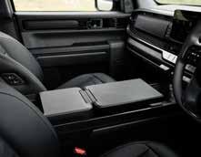
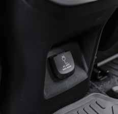
Fold out desk 240 V outlet
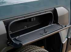
Storage in the rear wheel arch on high-spec models
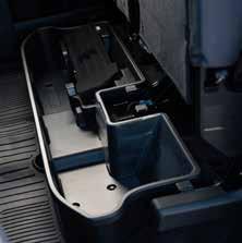
Storage under back seat
To survive heavy Australian towing, it features a water-to-air intercooler, high- and low-temperature radiators, and a heavy-duty cooling fan. See Diagram 11
The Kia Tasmans sold in Australia are homologated to meet Euro 5 emissions standards, so it uses a Diesel Particulate Filter (DPF) but omits the Selective Catalytic Reduction (SCR) system that the stricter Euro 6 rules require.
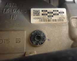
The 8-speed A8TR1-1 automatic transmission is derived from the longitudinal layout found in the performance-focused Kia Stinger sedan, with a dedicated external transmission oil cooler to keep temperatures down during towing. The transfer case has a low range and includes a 4A (Automatic 4WD) mode. This acts like an all-wheeldrive system, allowing the car to safely distribute variable power to the front axle. Mid-tier models utilise an auto-locking rear differential, while the flagship X-Pro trim upgrades to a driver-selectable electronic
rear locking differential (e-LD).
The Tasman is built on an allnew, dedicated ladder-frame chassis. The front suspension is a modern independent doublewishbone setup equipped with frequency-selective dampers, tuned specifically over thousands of kilometres on Australian roads to eliminate typical “ute bounce.”
The rear suspension uses a heavyduty, live rear axle supported by a four-leaf parabolic leaf spring pack. This setup allows the vehicle to safely manage a 3,500kg braked towing capacity and a substantial 350kg tow-ball mass rating. What is it like to drive?
On the road, the Tasman has a smooth ride and doesn’t feel like you are in a ute. The engine provides adequate performance with smooth power delivery, but lacks the sheer acceleration and fun of some of the PHEV ute options now available. Its boxy design pays major dividends on the inside, providing some of the best cabin ergonomics in the ute
segment, with excellent second-row seats and storage under them. The front centre console flips forward to create a mini desktop, and dual wireless charging pads are available to act as a mobile office when on-site. As with many other modern vehicles, there is a 240 Volt outlet for your gear. See Diagram 1 We didn’t have the opportunity to take the Tasman off-road, but other reviewers have praised its capabilities. It is one of the few factory-standard and showroom-spec 4x4s that have conquered Queensland’s brutal Beer O’Clock Hill.
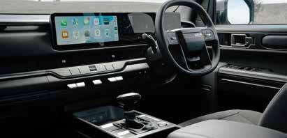
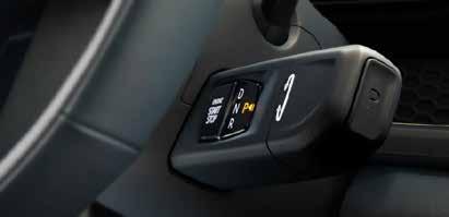
The one quirk on the higherspecification models is the location of the start button and gear selector, which are all on a stalk on the right side of the steering column, below the indicators. The start button is on the front of the stalk, and to select a gear, you will have to twist the end, don’t start reefing on it like the column shifter on your uncle’s old Falcon.
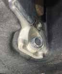
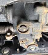
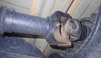
There is a single grease nipple on tailshaft
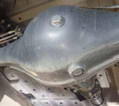
DIAGRAM 4 Rear final drive
Refill and level plug
Lower-spec vehicles have a T-bar shifter and a start button in the centre console.
Higher-spec vehicles have a stalk to the right of the steering column with the start button on the front. To select gears, twist the end forward or back. Use the button on the end for Park.
Press the button on the end of the stalk to select park. Base and middle-level vehicles are equipped with a traditional mechanical T-Bar gear lever situated directly on the centre console. See Diagram 3 What is it like to service?
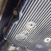
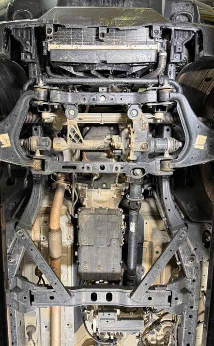
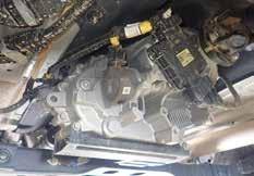
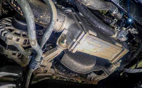
When on the hoist with the bash plates removed, all of the components are straightforward to access. All the drain-and-refill plugs for the driveline are easy to access. The sump plug and oil filter are in places that will drain without making a mess. The oil filter also has a drain plug. See Diagram 2
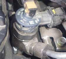
The fuel filter with a water drain port is conveniently attached to the chassis rail. See Diagram 10
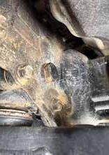
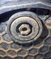
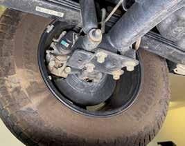
One interesting feature I haven’t seen before is what appears to be small drain channels coming out of the rear wheel bearing assemblies. I assume their purpose is to direct any oil that leaks from a failed axle seal away from the brake disc, which is nice of the Kia engineering team. See Diagram 12
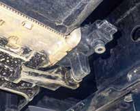
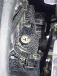
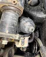
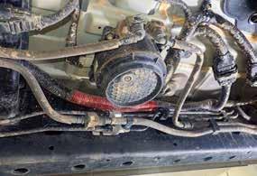
However, in my opinion, if I were planning to take the Tasman off-road a lot, I would make an additional bash plate at the rear of the transfer case, as I
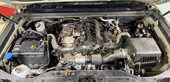
think the actuator and its wiring are vulnerable to snagging on sticks or being damaged by rocks. See Diagram 2 Under the bonnet, there seems to be enough room to access most components. However, they have installed a cover over the drive belts at the front of the engine, which could make inspection and replacement difficult. What makes this job harder is the location of the water-to-air intercooler, mounted in front of the crankshaft pulley. See Diagram 11 It appears to be mounted with only four bolts, which look easy enough to access, and I hope there is enough slack in the coolant hose so the intercooler can be moved out of the way to remove the belt covers and access the belts. If not, it looks like you might have to drain the intercooler coolant. We will have to wait and see which is the best way to do it. The timing belt for this engine has a replacement interval of 240,000 km (inspection at 120,000), with the coolant pump and tensioner replaced while you are at it. This applies to the diesel engine variants of the Kia Sorento, Kia
DIAGRAM 10 Fuel filter location
Engine Coolant
Intercooler Coolant
The fuel filter is mounted on left in front of the fuel tank. Water drain.
High AC Service Point
Low AC Service Point
Brake fluid PCM
Carnival, and Hyundai Santa Fe. However, I am not sure if these passenger vehicles have the drive belt covers that the Tasman has on its North/South-facing engine. Many Volkswagen 2.0L TDI
engines have a similar design, as discussed in the following article.
VW /Audi 2.0L TDI: Repeated Timing
Belt Failures
TechTalk March 2025, page 5704
DIAGRAM 11 Intercooler location and belt layout
There is no scheduled drive belt replacement; the first inspection is at 80,000km, and then every 20,000km thereafter. One possible cause of the repeated timing belt failures in the VW/Audi example was the failure of the serpentine drive belts. I am not saying this will be an issue for the Tasman, but if I were servicing one of these, I would find an easy way to inspect the belts behind this cover at each service and recommend replacing all belts at 120,000km when the timing belt inspection is due. The Tasman is backed by a 7 year, unlimited-kilometre warranty for private and general fleet buyers in Australia. But you will have to use your professional judgement as to what is best for your customers.
Modifications
Kia has produced a free-todownload Body Builders Guide to assist with the creation and installation of aftermarket components from the following site. kia.com/au/owners/manual
Conclusion
The Kia Tasman seems to be a good unit, with car-like comfort that hides its off-road capabilities. It is based on a tried-and-true engine and transmission fitted in a new platform, so we will have to wait and see how they stack up in a commercial application. From a service and repair perspective, there is nothing out of the ordinary (apart from the intercooler), so it looks like it will be a very straightforward vehicle to work on. Kia has reduced prices due to Tasman sales not meeting expectations, for several possible reasons. Firstly, there are a lot of other new utes on the market (unknown quality aside), and the bold styling choices Kia has made for the Tasman can be polarising. But it seems like a good car, and you can’t see it once you are in it.
DIAGRAM 12 Wheel bearing drain spout
Scan this code for the Body Builder Guide for the Kia Tasman
Looking from under the vehicle, the water-to-air intercooler is mounted in front of the crank pulley. This will make inspecting and removing the drive belts a bigger job.
We think this is a drain in case the axle seal leaks to keep oil off the brakes.
A/C Compressor Crankshaft Pulley
Alternator
A/C Belt
Alternator Belt
The basics of highvoltage batteries
What you need to know
Many in the automotive repair industry have the equipment to test 12 Volt car batteries, and giving customers a detailed state-of-health report is now considered a normal part of service for most workshops. But what about the high-voltage batteries in hybrid, plug-in hybrid and battery electric vehicles? This is part one of a series of articles to build on your knowledge of batteries and common terminology, and how that relates to high-voltage batteries. There is now a growing number of hybrid, EV, and PHEV cars on the road from a wide range of manufacturers. This means that there is a growing number of vehicles on the second-hand market with various types of highvoltage batteries that customers would like tested before they buy.
Or if they already own one, they would like to know the condition of their battery and how to get the most from it. This will require some teamwork from the driver and the technicians who service them. But first, we need some battery basics to understand. Battery basics
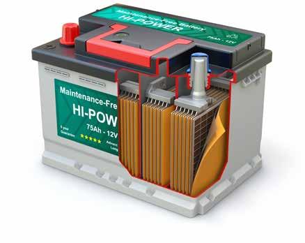
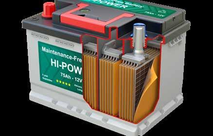
A battery cell stores energy as chemical potential and converts it directly into electrical energy. A typical 12-volt car battery has six lead-acid cells, each producing approximately 2 volts. These individual cells are connected in series, adding their outputs together to produce approximately 12 volts. They are all contained in a single casing, with the positive and negative terminals at the ends of the cell stack. Voltage and current flow can be checked across these terminals. See Diagram 1
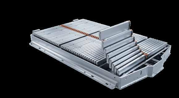
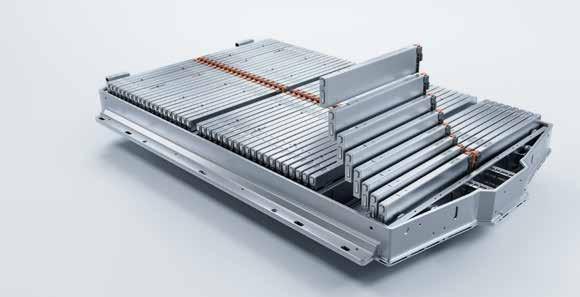
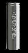
A high-voltage battery in a hybrid or EV could be made from a variety of chemicals and elements to form individual cells, which could be configured into cylinders like AAA or AA batteries in your TV remote, or pouch cells like in your mobile phone. The individual cells typically operate between 2.5V and 4.2V, depending on the cell chemistry. Groups of these cells are packed together to form modules with a higher combined voltage. The modules are connected to each other via bus bars, which increase the total voltage and current output. These connected modules are then packaged in a case to form the vehicle’s battery unit. A traditional hybrid could operate at 100-300 volts, while a PHEV might operate at 300-400 volts. A pure battery electric vehicle can produce 350 to 800 volts. See Diagram 2
Each cell uses exactly three core components: a negative electrode (anode) to release electrons, a positive electrode (cathode) to receive electrons, and an ion-conducting medium (electrolyte) that allows charged atoms (ions) to move between the anode and cathode, while completely blocking the flow of electrons. Together they store and release electrical energy.
Most low-voltage car batteries have six cells each producing 2 volts, which, when connected in series, create 12 volts.
Common HV battery cell designs
An EV battery pack provides 400–800V*, depending on make and model, and is composed of hundreds of smaller cells. The individual cells typically operate between 2.5V and 4.2V, depending on the cell chemistry and charge level.
Battery cells stacked together to make a module
*Some new systems operate at 1000V.
Battery Management Systems
Many modern ICE cars with a stop-start system use battery management systems (BMS) and commonly use voltage, current, and temperature sensors to manage the battery’s charge level.
For more information, see the following article.
Battery Energy Management Systems: New Battery Coding or Programming?
TechTalk August 2022, page 5264
In vehicles with high-voltage batteries, each battery module typically includes a temperature sensor and a voltage output, which
are connected to an electronic control unit that forms the BMS. The BMS’s purpose is to ensure the HV battery charges and discharges safely and to maintain all modules for maximum lifespan and reliability. It does this by monitoring the battery’s temperature and controlling its heating or cooling as required. This is to keep the battery at a comfortable temperature, typically between 15°C and 35°C.
The BMS also monitors the voltages of all modules and attempts to ensure they are all at the same voltage, balancing them where possible. The type of battery charger the vehicle is plugged into will
Not all EV chargers are the same DIAGRAM 3
(Mennekes/Type 2)
influence how the BMS manages the battery, and the BMS will record the type of charger used.
Types of Electric Vehicle Chargers
As with all batteries, the highvoltage batteries used in vehicles operate on DC (Direct Current) and are charged by DC. However, the electric motors that drive the car require AC (Alternating Current), and the power that comes from the grid is also AC. So, the car will have an inverter to convert the DC from the battery to AC to drive the car, and then reverses this for regenerative braking from AC back to DC. Many cars also have
(Combo CCS 2)
Many modules make up a HV battery pack
a separate onboard charger that converts AC from the grid to DC to charge the battery. As a result, there are two main categories of battery charging methods: AC (Alternating Current) and DC (Direct Current).
There is a wide variety of charging connectors depending on the year and manufacturer. But no matter the charging method, the car’s battery management system will communicate with the charger to ensure the battery’s safety. But more on how charging impacts the battery life later. See Diagram 3 State of Health (SOH)
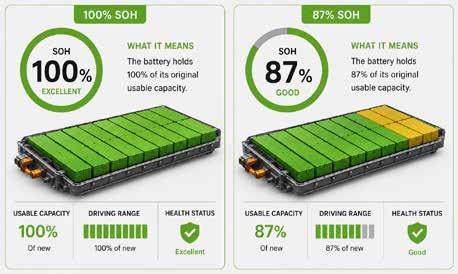
In simple terms, the battery’s state of health (SOH) is a measure of its capacity, like a fuel tank’s capacity. If a tank is made with a capacity of 50L when new, over time, sediments build up in the bottom of the tank, or the tank now has some dents, this reduces the tank’s capacity, and now it might only hold 45L, so it has lost 10% capacity through wear and tear. This would be an SOH of 90%. See Diagram 4
The battery management system will use information from temperature and voltage sensors, as well as internal resistance, charge cycles, driving behaviour, temperature exposure, and charging patterns, so that an algorithm in the software can
DIAGRAM 5
make an educated guess about the battery’s SOH or remaining capacity. This will be presented as a percentage of the remaining energy capacity relative to the battery’s capacity when new. It should be remembered that different battery and vehicle manufacturers use different algorithms and software systems to calculate SOH, so the same battery used in different vehicles could yield different SOH percentages. External factors like ambient temperature, the last time the battery was fully balanced, and recent driving behaviour can
State of Health and its decline
cause an SOH reading to fluctuate by a few percentage points between tests, which is normal. State of Charge.
While SOH measures the size of the “tank,” State of Charge (SOC) tells you how full that tank is at this moment, but it is, again, an intelligent estimate from software and algorithms of the remaining usable charge in a battery relative to its full capacity. Imagine our fuel tank analogy, you can’t see inside, but you record exactly how many litres you pour in and out. If you know you started with 50 litres and poured out 5, you have 45 litres left.
SOH reduction in a high-voltage battery is a natural but permanent process caused by several internal chemical and physical “wear and tear” mechanisms, such as loss of active lithium or electrode material decay, and cell imbalance.
AGE / MILEAGE
i Sources:Recurrent
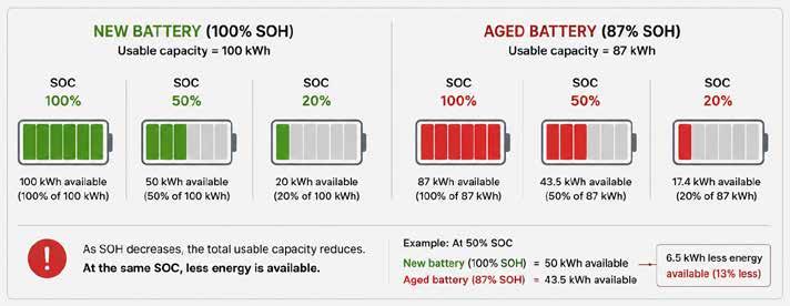
In battery terms, if your total capacity was 50 kWh and you used 5 kWh, your State of Charge (SOC) would drop from 100% to 90%. But is 100% on the dashboard gauge 100% at the battery? See Diagram 4 Your dashboard’s 100% is often a “usable” 100%, not the battery’s total chemical limit or capacity. Manufacturers often build in “buffers” at the top and bottom. For example, a 100 kWh battery
might only allow you to use 90 kWh. When your SOC shows 0% on the dash, there is often a hidden reserve left to prevent permanent chemical damage to the battery.
SOH verses SOC
The latest research suggests that SOH declines over time and with usage, following a non-linear decay curve, often dropping slightly in the first year before stabilising at an
average loss of about 1.8% per year. As capacity decreases, the BMS recalculates the SOH to determine how much charge the battery can hold. When it displays the SOC on the dash or in your diagnostic tool, it shows a percentage of the current, reduced SOH. Therefore, if the battery is fully charged, the SOC will be 100% while the SOH is 90%, indicating a 10% reduction in capacity and vehicle range. See Diagram 6
Difficulty in fast EV charging
DIAGRAM 7
A battery with an SOH of 90–100% is generally considered to be in excellent condition, with minimal degradation and normal operation expected. Between 80–90% SOH, some ageing is present, but the battery is still considered serviceable. Once SOH falls into the 70–80% range, there is a noticeable reductions in driving range but the performance could still be ok, Batteries below approximately 70% SOH are usually considered heavily degraded and the vehicle may experience significant range loss, reduced performance, increased charging limitations (fast charging is now unavailable), or fault codes from the BMS . How charging speed can impact battery SOH
Charging significantly influences battery SOH because it generates heat, chemical stress, and mechanical strain within the battery cells. Every time an EV battery charges and discharges, small amounts of degradation occur, gradually reducing its usable capacity and increasing its internal resistance. The rate of this degradation depends heavily on how the battery is charged, how often it is charged, and the temperatures involved. One of the biggest factors affecting SOH is charging speed. See Diagram 3
DC fast charging places much higher current demand on the battery compared with slower AC charging. Higher charging current increases heat generation and accelerates chemical ageing within the cells. While modern EVs are designed to handle fast charging, repeated high-speed charging can accelerate degradation if thermal management is inadequate. The dangers of 100%
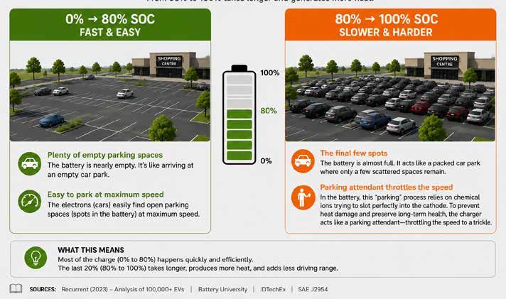
Many use the car park analogy when describing the speed of battery charging. When the battery is flat, it is like an empty car park at a shopping centre. There are plenty of free spaces, and it is fast and easy to park. But once the car park is about 80% full, it gets harder to find a space, and other drivers are also looking for the remaining spaces, so it takes more time and energy and makes many drivers get hot under the collar. Once the battery is about 80% full, it requires more energy and time, which produces more heat, to charge it to 100%. See Diagram 8 During the final stage of charging, the BMS reduces current to protect the cells as voltage approaches maximum limits. This is why charging slows significantly above approximately 80% SOC. The charging curve is designed
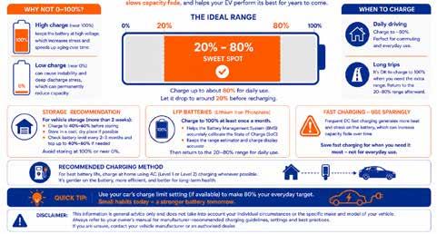
to minimise damage while maintaining battery longevity. Charging the battery to very high State of Charge (SOC), particularly close to 100%, also increases stress on lithium-ion cells. At high SOC levels, cell voltage rises significantly, increasing the likelihood of electrolyte breakdown, lithium plating, and long-term chemical degradation. For this reason, many manufacturers recommend daily charging limits around 80–90% for normal driving, reserving 100% charging mainly for long trips. See Diagram 9
Cell imbalance
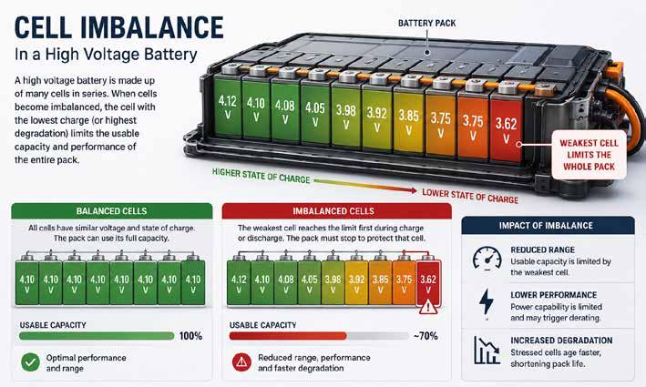
The cells in an HV battery don’t tend to fail all at once, but a single bad cell can bring the whole battery down. Cell imbalance in HV batteries occurs when individual cells within a battery pack hold different voltages or SOC. See Diagram 8 Because HV packs link dozens or hundreds of cells together, this mismatch limits overall capacity, lowers electric range, and triggers the BMS to restrict performance. So why is all of this important Historically, EVs have depreciated in market value faster than petrol cars, often losing around 25% of their value in the first year compared to roughly 11.5% for petrol vehicles.
Cell imbalance
DIAGRAM 8
However, some models, particularly luxury brands, can lose nearly half their value within 3–5 years. This may be due to buyer-perceived “unknown” variables, such as the worry that the battery will fail shortly after purchase, requiring tens of thousands of dollars in replacement costs. However, recent research suggests that EV batteries are extremely robust, with a projected lifespan of 15 to 20 years and an average annual capacity degradation of just 1.8% to 2.3%, provided the vehicle and battery are maintained and charged correctly.
Real-world performance consistently exceeds manufacturer expectations and warranty parameters (which typically guarantee 70-80% capacity over 8-10 years). So, the dramatic drop in market value might be an overreaction.
Conclusion
Having basic knowledge of the construction of high-voltage batteries and the factors that can affect their service life can help you and your technicians service these vehicles to get the most out
THE 20-80% RULE
The best practice for a healthy, long-lasting battery Keeping your battery between 20% and 80% most of the time, reduces stress on the cells, slows capacity fade, and helps your EV perform at its best for years to come.
IDEAL RANGE
of them. See the following article
High-Voltage Battery
Cooling System Service
TechTalk April 2021, page 5024
You may also have to educate your customers with these types of vehicles on how to develop charging and driving habits to ensure they are not inadvertently reducing their battery’s service life and potential resale value. See Diagram 9
Now that we have some basics
under control, the next article in this series will cover how to check the condition of a high-voltage battery in Toyota and Lexus hybrid vehicles with your diagnostic tool. If you work on cars with highvoltage systems and you have completed the HV courses, log on to VACC MotorTech and upgrade to our HV Data package, or call VACC’s TechAdvisory Service for more information.
Restore headlights to as new condition
3 Step Process – Yellow-X cleans away the oxidisation on the lens, then the UV Clear Coat wipe re-applies the sealing coat to protect the clean lens. Suitable for mild to medium oxidised lenses. (For heavily oxidised lenses use HRK01.)
For more information and all sales enquiries contact: Ph: (03) 9336 2066 Email: enquiries@invisionsales.com www.invisionsales.com
Chrysler 300:
No start after a flat battery
2011-2021 Chrysler 300
A flat battery that requires a jump start was once a relatively straightforward way to get a car running again, but it can be hitor-miss now with cars that have many aging electronic control systems and modules with failing memory. VACC’s Technical Advisory Service has recently received industry feedback from a VACC MotorTech subscriber about a common fix to get a second-generation Chrysler 300 going again that could save you diagnostic time and headaches.
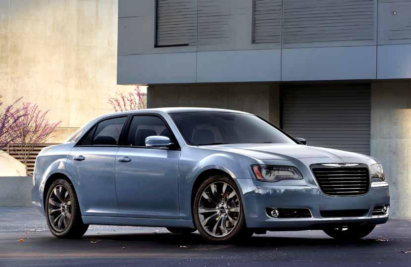
The original 1955 Chrysler C-300 was a massive, imposing, luxury brute powered by a 300-horsepower Hemi V8. It is widely considered America’s first true muscle car. In 2005,
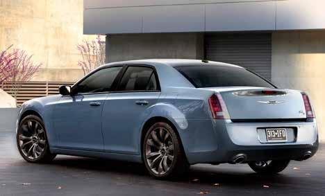
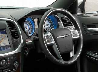
Chrysler pulled off a masterclass in leveraging heritage to completely save their brand’s image with the introduction of a modern reimagination of its 50-year-old predecessor. See Diagram 1
The modern Chrysler 300 became an overnight sensation with bold, retro-modern styling, unapologetic American power, and upscale luxury, thanks to design input from MercedesBenz (a partner at the time). The second generation was released in 2011 and was well received, but as public tastes changed and sales declined, production of right-hand-drive versions ended in 2021, and all variants
Module failures
As with many other vehicles of this era, there are many computercontrolled systems. The 300 uses a CAN Bus architecture and many electrical components from Mercedes-Benz for refined operation. However, as these modules age, they appear to be more prone to failure when the power supply is interrupted. See the following articles for examples of module failures in other vehicles.
• Ford FG Falcon and SZ Territory ICC Unit Failures
TechTalk Sept 2018, page 4576
• BMW / Mini Footwell Module (FRM) Issues
The 1955 Chrysler C-300 is widely celebrated as America’s first true production muscle car. It beautifully combined raw NASCAR performance with high-end luxury, singlehandedly launching Chrysler’s famous 300 “Letter Series” legacy.
DIAGRAM 1 The classic that inspired the 300
The second-generation 300 is now on this list, but it seems to be easy to fix once you know how.
The trouble
After a flat battery, power disconnection, or jump-start, the second-generation Chrysler 300 has been known to enter a no-start condition; the ignition turns on, but the engine will not crank. The check engine light may or may not be on, but the red security light will be flashing at 1 Hertz, which is a clue. With a compatible diagnostic tool, the following codes could be stored. NOTE: From approximately 2018 onwards, these vehicles could be fitted with a Secure Gateway Module (SGW). See the following article for more details.
Secure Gateway (SGW) Modules: Which cars have them, and how to gain access: TechTalk March 2026,page 5896
B1A8A-00: Multi-Mode VIN Handshake Failure
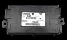
This code is stored in the Radio Frequency Hub (RFH) under the parcel shelf. See Diagram 2
Most Chrysler 300s imported into Australia were fitted with the Thatcham security system with an option identification code of LS9. The easiest way to check this is to use the following link, enter the vehicle’s VIN, and an equipment list will be generated with all the car’s options. Scroll through the pages, and you should see “Thatcham Security Equipment”. https://fcagroup.my.site.com/ RAM/s/equipment-listing
If so, a Multi-Mode VIN Handshake could fix the no-start problem. A VIN Handshake is an electronic security check where a vehicle’s various computer modules broadcast and verify the Vehicle Identification Number (VIN) to ensure they all belong to the same car. It acts as an internal anti-theft and antitamper system to prevent the installation of unauthorised or stolen parts. When a command is sent, the receiving module checks the transmitted VIN against its own internally stored VIN. If the VINs match, the handshake is successful, and the modules cooperate.
P0513: Invalid SKIM Key
This code is stored in the vehicle Powertrain Control Module (PCM), which controls the engine and transmission. A SKIM key (Sentry Key Immobiliser Module key) is a specific type of car key / fob equipped with an internal radio frequency (RF)
The Radio Frequency Hub (RF Hub or RFH) is a control module that manages wireless communication between the vehicle and the keyless entry remotes and doubles as the receiver for the wireless signals sent by the pressure sensors inside the tyres.
microchip. It is primarily used in Chrysler, Dodge, and Jeep vehicles manufactured since the late 1990s. The car’s antenna sends the code to your car’s SKIM module, or in this case, the Radio Frequency Hub (RFH). If the code matches one of the authorised keys programmed into the car’s computer (PCM), the engine starts normally. The following VIN handshake procedure should reestablish communication between the Radio Frequency Hub (which communicates with the key fob) and the PCM, allowing the engine to start. VIN handshake procedure
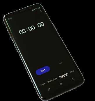
Before starting this procedure, ensure the vehicle’s battery is fully charged or connected to a stabilised power source, as you can’t afford a power outage. Next, you will need a stopwatch as the steps are time-dependent; most modern smartphones will have one built in. See Diagram 3
Most modern phones have a stop watch.
DIAGRAM 3 A stop watch will help you fix this issue
DIAGRAM
Using the stop watch and the start stop button you can engage the Multi-Mode VIN
Handshake procedure
Start the stop watch and let it run.
Press the start button twice to go to RUN.
After each minute the start button must be cycled through OFF-ACC-RUN-OFF within the 20 second window. Press the button twice to go to RUN. Press the button once to go to OFF.
NOTE: If you miss a window the procedure must be started again.
1. Ensure your foot is OFF the brake pedal.
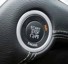
2. Start the timer and, at the same time, press the start/stop button twice (2) to place the ignition in the RUN position. Press the start/stop button again (only once) to turn the ignition to the OFF position. See Diagram 4
3. When the timer reads 1 minute, within 20 seconds, cycle the ignition from OFF-ACC-RUN-OFF.
NOTE: If you cycle the key outside of the 20-second window, during this or any of the following steps, you will need to start again.
4. When the timer reads 2 minutes, within 20 seconds, cycle the ignition from OFF-ACC-RUN-OFF.
5. When the timer reads 3 minutes, within 20 seconds, cycle the ignition from OFF-ACC-RUN-OFF.
6. When the timer reads 4 minutes, within 20 seconds, cycle the ignition from OFF-ACC-RUN-OFF.
7. When the timer reads 5 minutes, within 20 seconds, cycle the ignition from OFF-ACC-RUN-OFF.
8. Once the above has been completed, crank the engine and see if the problem if gone.
9. Clear the DTCs.
It appears that a software update is available that could prevent this situation, but some cars may not have received it. If you have a customer with one of these vehicles, check that the software is up to date to avoid problems if the power supply is interrupted again. For more information on the Chrysler 300 and many other vehicles in the Stellantis group, log onto VACC MotorTech or call VACC’s TechAdvisory service.
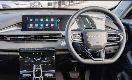
As of early 2026, the Chery Tiggo 4 is the best-selling small SUV in Australia, with sales up over 119% compared to the same period in 2025. It is available in both internal combustion and hybrid versions, offering significant value for money, which could account for the popularity.
As with many other modern vehicles, there is a service light that needs to be turned off after each service, and conveniently, there is a simple procedure.
Failing to service your car within the manufacturer’s specified intervals can void your warranty. For a car like the Chery Tiggo 4, which has a 7-year warranty, the service light is your best friend for keeping that coverage active. However, obtaining the correct information to reset service indicators can be tricky, and no guarantee that it is applicable to the Australian market. The following procedure has been confirmed by a VACC MotorTech subscriber.
Manual Service Light Reset
Via Instrument Cluster
1. Turn the ignition to the “ON” position (do not start the engine).
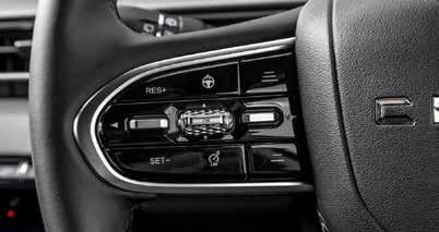
2. Using the arrow buttons on the left side of the steering wheel, scroll sideways through the icons at the top of the instrument cluster display to highlight the circular “Gear” icon. See Diagram 1
Use the arrow buttons below to scroll side ways until the “Gear” icon is in the middle and highlighed at the top of the screen.
DIAGRAM 1 Step 1 - Icon and button locations Arrows OK Button
Highlight “Service Milage Reset” then press the “OK” button
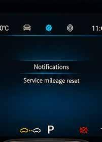
3. There should now be options on the display for “Notifications” and “Service Mileage Reset” See Diagram 2
4. Using the buttons on the left side of the steering wheel, select “Service Mileage Reset”
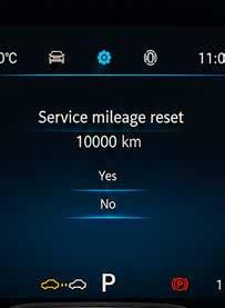
5. The display should now show “Service Mileage Reset 10000km” See Diagram 3
6. Scroll to highlight “Yes”.
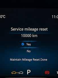
7. Then press the “OK” button to reset. See Diagram 4
8. Turn the ignition off.
9. Turn the ignition on and confirm that the service indicator has reset. This method could work on other Chery models, but this has not been tested.
For more service light resets on a wide range of makes and models, log onto VACC MotorTech of call VACC’s TechAdvisory Service.
If the above method fails, you can attempt the following via the infotainment screen. This method has not been locally validated. Navigate to Settings
>Vehicle Settings (you may have to swipe left to the other page of options)