

Product: BACKHOE LOADER
Model: 416 BACKHOE LOADER 5PC
Configuration: 416 BACKHOE LOADER 5PC00001-06191 (MACHINE) POWERED BY T4.236 DIESEL ENGINE
Disassembly and Assembly
BACKHOE LOADER ENGINE
Updated -08/03/2006
SENR31290035
Crankshaft Rear Seal
SMCS - 1161-011; 1161-012
Remove Crankshaft Rear Seal
START BY:
a. remove flywheel housing
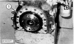
1. Remove the boltsand socket head screws that hold oil seal housing (1) to the engine block.
2. Move the oil seal housing off the dowels, and remove the gasket.
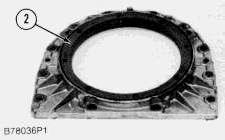
3. Remove crankshaft rear seal (2) from the seal housing.
Install Crankshaft Rear Seal
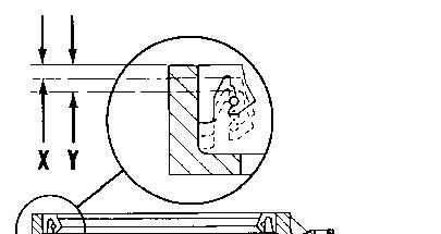

1. Check the flange of the crankshaft for a wear groove. If a wear groove exists, install the new seal in the housing until dimension (X) is 3.18 mm (.125"). If there are two wear groovesin the flange, install the seal in the housing to a depth of 6.35 mm (.250 in.) - dimension (Y).
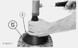
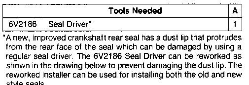
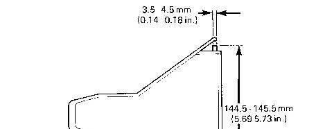
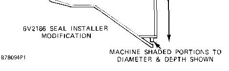
2. Use tool (A) to install the crankshaft rear seal into the seal housing. Be sure the spring loaded lip is toward the inside of the seal housing. The seal surface must be clean and dry. Do not handle the lip of the seal.
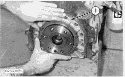
3. Put the gasket in position on the dowels.
4. Put seal housing (1) in position on the dowels.
5. Install the boltsand socket head screws to hold the seal housing in position.
END BY:
a. install flywheel housing
Product: BACKHOE LOADER
Model: 416 BACKHOE LOADER 5PC
Configuration: 416 BACKHOE LOADER 5PC00001-06191 (MACHINE) POWERED BY T4.236 DIESEL ENGINE
Disassembly and Assembly BACKHOE LOADER ENGINE
Media Number -SENR3129-00 Publication Date -01/02/1986 Date Updated -08/03/2006
SENR31290037
Crankshaft
SMCS - 1202-011
Remove Crankshaft
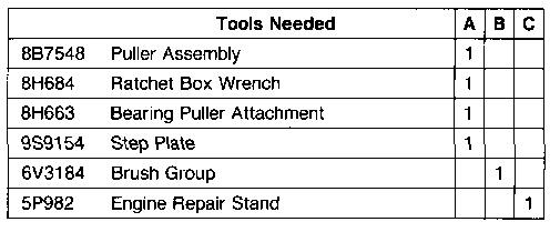
START BY:
a. remove engine
b. remove crankshaft rear seal
c. remove oil pump
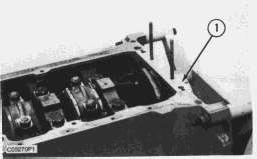
1. Install the engine on tool (C). Fasten it in position at the flywheel end as shown.
2. Remove bridges (1) and the seals.
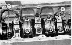
3. Remove connecting rod bearing caps (2) and (3). Be sure the connecting rods, connecting rod caps and bearings are labeled so the partscan be matched at assembly.
NOTE: Be sure the location is marked on the main bearing caps before they are removed. The stamped location number is toward the camshaft.
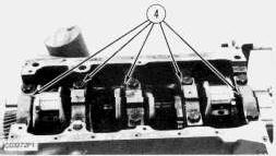
4. Remove five main bearing caps(4). Remove the bearings from the main bearing caps, and remove the thrust washers from the center main bearing cap. Put identification markson the bearings as to their location in the engine.
5. Remove the connecting rod bolts, and push the pistons to the top of their stroke. Do not damage the crankshaft journals with the connecting rod bolts.
This is the sample of the manual click on the download link for complete manual
DOWNLOAD LINK
For some reason if link does not work download this pdf and then click
Caterpillar 416 Service Manual PDF, CAT 416
Excavator Repair Manual, Caterpillar 416 Workshop Manual, CAT 416 Service Repair PDF, Caterpillar 416 Manual Download, CAT 416 Excavator PDF Manual, Caterpillar 416 Repair Guide, CAT 416 Technical Manual PDF, Caterpillar 416 Shop Manual, Caterpillar
416 PDF Service Manual, CAT 416 Excavator Service Guide, Caterpillar 416 Repair PDF Download, CAT 416
Workshop Repair Manual, Caterpillar 416 Technical Service Manual, CAT 416 Shop Repair PDF, Caterpillar
416 Excavator Manual PDF, CAT 416 Maintenance & Repair Manual, Caterpillar 416 Service Repair Guide, CAT 416 Hydraulic Repair Manual, Caterpillar 416 Factory Service Manual, CAT 416 Technical Workshop Guide, Caterpillar 416 Complete Repair Manual, CAT
416 Excavator Workshop PDF, Caterpillar 416
Professional Service Guide, CAT 416 Electrical Wiring Manual, Caterpillar 416 Diagnostic Manual PDF, CAT
416 Excavator Shop Manual Caterpillar 416 OEM