MAUNGAWHAU
UPTOWN RECREATION CENTRE
AKIRAHO STREET
SYLVAN AVE E
MAUNGAWHAU TRAIN STATION
URBAN TRAIL
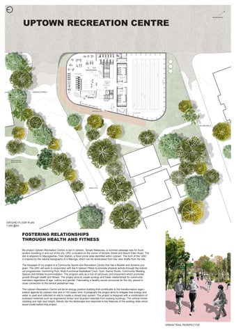
GROUND FLOOR PLAN 1:200 @A3
FOSTERING RELATIONSHIPS THROUGH HEALTH AND FITNESS My project ‘Uptown Recreation Centre’ is set in Uptown, Tamaki Makaurau, a common passage way for Aucklanders travelling in and out of the city. URC is located on the corner of Akiraho Street and Mount Eden Road. The site is adjacent to Maungawhau Train Station, a flood prone area identified within Uptown. The form of the ‘URC’ is inspired by the natural topography of a Maunga, which can be showcased from key view shafts from the site. The Kaupapa of my project is a Community Sports and Recreation Centre that has a flexible and dynamic program. The URC will work in conjunction with the 6 Uptown Pillars to promote physical activity through the individual programmes: Swimming Pool, Multi-Functional Basketball Court, Gym, Dance Studio, Community Meeting Spaces and Athlete Accommodation. The program aids as a hub of sanctuary and enjoyment which promotes growth through health and fitness. The project aims to create synergy and foster relationships for community members regardless of age, culture and gender. Fabricating a healthy social concourse for the city, placed in close connection to the central pedestrian way.
UPTOWN CENTRE RECREATION MAUNGAWHAU MAUNGA TRAIN STATION
The Uptown Recreation Centre will be an energy positive building that contributes to the transformative regeneration agenda for Uptown now and in 100 years’ time. Ecologically the project aims to mitigate how energy and water is used and collected on site to create a closed loop system. The project is designed with a combination of biobased materials such as engineered timber and recycled materials from existing buildings. The vertical timber cladding and high stud height, blends into the landscape and responds to key features of the existing villas which stood onsite before this project.
URBAN TRAIL PERSPECTIVE
PARTI DIAGRAM void APARTMENT SUITES
LOBBY
down LIFT
THIRD FLOOR PLAN 1:200 @A3
UNISEX TOILETS
REFRESH / CAFE
down CLIMBING BRIDGE
down
MEETING ROOM
VOID
BASKETBALL MEZZ / SEATING
MEETING ROOM
BASKETBALL COURT
SWIMMING POOL PERSPECTIVE
down
FOYER MEETING ROOM
MEETING ROOM
VOID
VOID
BREAKOUT
down
UNISEX TOILETS
BASKETBALL COURT PERSPECTIVE
SECOND FLOOR PLAN 1:200 @A3
MATERIALS PALLETTE
MOUNT EDEN ROAD
FIRST FLOOR PLAN 1:200 @A3
rafters over CLT with 300mm Gutex Multitherm breathable wood fibre insulation between to meet minimum 0.11 W/m2K treated timber battens and counter battens to create a 50mm cavity to roof and wall
barge board
perimeter soffit vent Soffit Lining
Pro Clima Solitex Fronta Quattro breather membrane - overlaps sealed with Pro Clima Tescon Invis
CLT structural floor panel to structural engineers design with exposed internal finish
grey line denotes downpipe within cavity, external cladding to this area should be easiliy removable to allow for maintenance
wax based end grain sealant to all exposed edges of CLT
FLOOR DETAILS ARE REPEATED FROM 1ST TO 3RD. TYPICAL DETAILS
treated timber battens and counter battens to create a minimum 50mm cavity, where insulation is not able to support a secondary batten layer should be included within the insulation
160mm Gutex Multitherm breathable wood fibre insulation to meet minimum 0.18 W/m2K u-value CLT structural wall panel to structural engineers design with exposed internal finish with joints taped using Tescon Vana Tape
Pro Clima Solitex Fronta Quattro breather membrane - overlaps sealed with Pro Clima Tescon Invis joints taped using Tescon Vana Tape
galvanised fixings to structural engineers details
open state cavity barrier for ventilated cavities, continued through insulation where combustible
floating floor comprised of dense boards and acoustic insulation, depth to suit acoustic requirements and conceal fixing brackets if exposed CLT structural floor panel to structural engineers design with exposed internal finish wax based end grain sealant to all exposed edges of CLT tongue and groove timber cladding
NORTH - SOUTH SECTION 1:200 @A3 treated timber battens and counter battens to create a minimum 50mm cavity, where insulation is not able to support a secondary batten layer should be included within the insulation
CLT structural wall panel to structural engineers design with joints taped using Tescon Vana Tape 160mm Gutex Multitherm breathable wood fibre insulation to meet minimum 0.18 W/m2K u-value
Pro Clima Solitex Fronta Quattro breather membrane - overlaps sealed with Pro Clima Tescon Invis tongue and groove timber cladding
service zone created between timber battens
open state cavity barrier for ventilated cavities, continued through insulation where combustible
plasterboard lining with skim finish wax based end grain sealant to all exposed edges of openings
insect mesh to base of ventilated cavity breather membrane returned into window opening and lapped and sealed with window using Extoseal Encors Tape
timber window cill
breather membrane returned into window opening and lapped and sealed with window using Extoseal Encors Tape
FLOOR DETAILS ARE REPEATED FROM 1ST TO 3RD. TYPICAL DETAILS
Pro Clima Solitex Fronta Quattro breather membrane - overlaps sealed with Pro Clima Tescon Invis
160mm Gutex Multitherm breathable wood fibre insulation to meet minimum 0.18 W/m2K u-value
treated timber battens and counter battens to create a minimum 50mm cavity, where insulation is not able to support a secondary batten layer should be included within the insulation
CLT structural wall panel to structural engineers design with joints taped using Tescon Vana Tape service zone created between timber battens with plasterboard lining and skim finish
tongue and groove timber cladding
galvanised fixing brackets to structural engineers details wax based end grain sealant with dpc below floor finish to suit project damp proof membrane above cast in situ concrete slab to structural engineers design
dpm lapped at least 50mm down the slab edge damp proof course min. 150mm above external ground level insect mesh to base of ventilated cavity 150mm min
brick plinth finish to external leaf of foundation wall
WEST - EAST SECTION 1:200 @A3
rigid xps insulation to cavity of foundation wall
reinforced concrete footing to structural engineers design
FACADE DETAIL 1:50@A3
rigid insulation to meet minimum 0.13 W/m2K on membranes as required 140mm lightweight thermally efficient blockwork strip foundation to structural engineer design
(BY OTHERS) TOP COPING PRIMARY SUPPORT STRUCTURE SUPPORT STRUCTURE (HILTI HELPING HAND SYSTEM OR SIMILAR) WATERPROOF BACKING BOARD (12MM VERSAPANEL ECO SHEET)
REAR DRAINAGE LAYER (4.5MM GEOTEXTILE DRAINAGE LAYER) LINE OF RISER FLASHING
RAIL CARRIER SYSTEM (26MM ALUMINIUM RAIL TO SUIT MODULAR PANELS)
PANEL BOX (STANDARD PANEL MODULE 600x450x62MM) GROWING MEDIUM (GRODAN) CAPILLARY BREAKS (GEOCOMPOSITE DRAINAGE LAYER)
DRIPLINE (16MM DIAMETER PRESSURE COMPENSATED DRIPLINE) DRIPLINE COVER STRIPS (RIGID PVC EXTRUSION COVER STRIP)
EAST ELEVATION 1:200 @A3
REAR DRAINAGE LAYER (DRAIN INTO GUTTER)
FFL
GUTTER (114MM WIDE PVC GUTTER)
GREEN WALL DETAIL 1:5@A3
SUMMER SOLSTICE WINTER SOLSTICE
SOLAR ENERGY
INVERTER
ECO POWER TREADMILL AND BIKES
BATTERY
POWER
RAIN WATER HARVESTED
TANK 3 X 50,000L
PUMP PLANT ROOM
SINKS ,SHOWERS, LAUNDRIES
SECONDARY PUMP PLANT ROOM
GREY WATER TREATMENT PLANT
GREY WATER
TOILETS
BLACK WATER
ECO FRIENDLY SEPTIC TANK
OVERFLOW GARDEN IRRIGATION
FUNCTIONAL SYSTEMS DIAGRAM 1:200 @A3