6 minute read
An innovative mechanical design system: Developed for engineers by engineers

Deo du Plessis Mechanical Engineer, Spoormaker & Partners
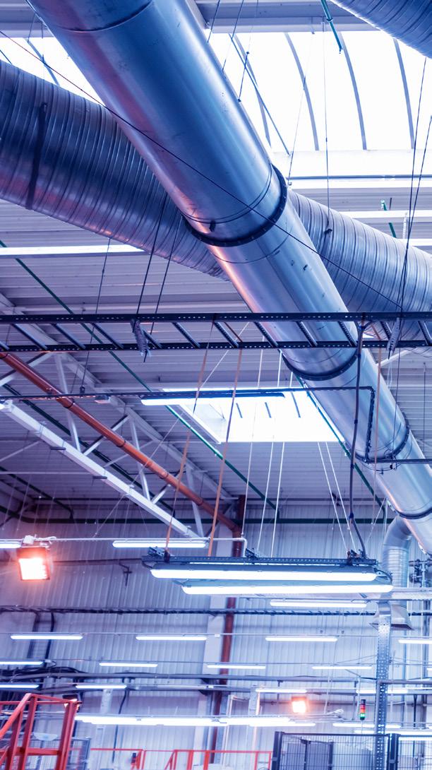
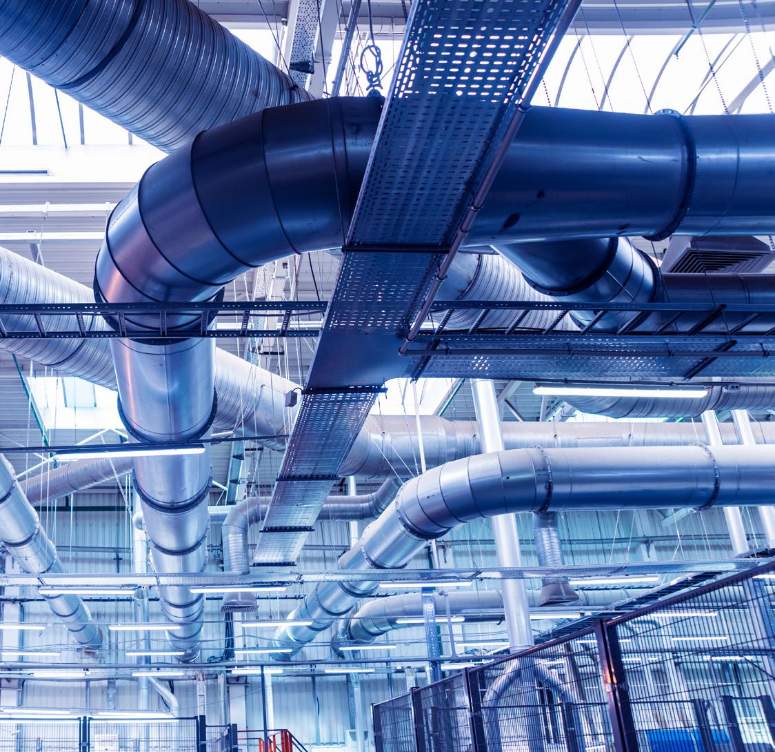
The University’s iconic new Engineering 4.0 facility features a state-of-the-art heating, ventilation and air-conditioning (HVAC) installation that combines specific laboratory technical requirements, energy efficiency, comfort and aesthetics. The 6 800 m 2 facility is an expansion of the existing facilities of the Department of Civil Engineering, as well as a common multivolume foyer that will link the building to future phases as the facilities expand even further.
DESIGN CRITERIA
Engineering 4.0 comprises a variety of spaces, each requiring different and room-specific design conditions. These include enclosed specific-use laboratories, open-plan training laboratories, curing and high-humidity rooms, sample preparation rooms, workshops, patch and server rooms, offices, a foyer and an auditorium. The tests and experimental work being conducted in the various laboratories typically involve a range of concrete, bitumen, asphalt and soil sample preparation and property testing under different conditions.
The associated mechanical design criteria for the spaces therefore provided unique engineering challenges. The two humidity rooms in the concrete laboratory, where concrete samples are treated and tested for creep, for example, require indoor conditions with a relative humidity of 95% and a temperature of 25 °C, as opposed to the laboratory itself and the curing rooms, which have a normal relative humidity and a temperature in the range of 22.5 °C. Ventilation needs therefore involved adhering to regulatory fresh air and fire rational requirements, while ensuring that testspecific ventilation needs were met.
In addition to HVAC and building management systems (BMS) services, the various spaces and laboratories in the building required other building services such as a compressed air network, various laboratory gas supplies, a hydraulic network to heavy machinery, and electrical and wet services to the various pieces of laboratory equipment and services. The design challenge was therefore to ensure that the individual laboratory needs were met, while providing the most sustainable design possible, within the context of a service-intensive and aesthetically sensitive building.
HVAC SYSTEM
The HVAC system involves a central air-cooled, chilled and hot water generation plant as a cooling and heating source, located at ground level. Chilled water at 8 °C and hot water at 50 °C is circulated via a four-pipe, closed-loop piping system to a network of air handling and fan coil units. The pumping arrangement includes a decoupled primarysecondary loop with hot and cold buffer tanks and variable-volume secondary pumps to ensure that pumping power is minimised whenever possible, in line with the cubic flow-power affinity law. Using a four-pipe system reduced the baseline HVAC electrical energy usage by 68% with an estimated payback period of 3.9 years. No water-consuming heat-rejection systems were used, and all refrigerants were specified with an ozone depletion potential of zero.
The laboratories of the South African National Roads Agency Limited (SANRAL) (the National Roads Materials Reference Laboratory and the Training Laboratory) are served by a series of above-ceiling chilled-water fan-coil units and various ventilation systems. A dedicated fresh air unit provides filtered, tempered and preconditioned fresh air to all spaces. A general central extraction system ensures neutral pressure in general laboratories. An independent bitumen extraction system ventilates from canopies and grilles located over oven areas. Seven different fume cupboards ensure that tests involving toxic gases can be carried out safely. These fume cupboards are connected to two dedicated extraction systems using centrifugal fans and above-roof-level exhausts. Each fume cupboard extraction system is also interlocked with a dedicated fresh-air make-up system to
ensure that the airflow in the rooms is correctly balanced, with or without operational cupboards. Safety features such as no-flow warnings and run statuses are indicated on purpose-made indicators in the user space. These systems are all located in a single plant room to be effectively screened. A seemingly complex, but carefully planned plant room space separates intake and exhaust air, while ensuring the required maintenance access, coordination and identification of all seven subsystems.
The concrete laboratories are served by various internal subsystems and a dedicated fresh-air unit located in an external screened plant room. The large multi-volume, open-plan heavy machinery laboratory is ventilated with tempered and preconditioned fresh air to minimise energy usage, with air supplied via long-throw jet nozzles to increase air velocity at ground level and improve occupant thermal comfort in a semi-industrial environment. Various enclosed laboratories are air conditioned, using exposed chilled-water fan-coil units and ventilated in accordance with the room requirements. The PVC ducting and spark-proof ventilation systems are utilised where chemical corrosivity and explosive risks are applicable. The materials handling area where raw materials are loaded and distributed is separated from the main laboratory and inversely ventilated with fresh air from a high level and extraction at a low level. This ensures that the space is always under negative pressure and properly ventilated, and also that the dust particles, which are heavier than air, are captured effectively at a low level.
A sample preparation room is used to cut and prepare concrete samples, resulting in a high dust loading of fine particles. This space is ventilated by means of various canopies and strip curtain combinations to effectively capture concrete dust at the source, extracting it via high-velocity ducting to an external industrial baghouse filtration system. The system ensures high-efficiency filtration, capturing extracted concrete dust in a series of cartridges and baghouse hoppers that are automatically pulsed clean via a compressed air nozzle manifold before the clean air stream is sound attenuated and exhausted to the atmosphere.
The concrete laboratories include five climate rooms, where samples are cured in heated water baths. These rooms are air conditioned via dedicated chilled-water fan-coil units located outside the rooms to avoid the continuous exposure of systems and controls to high roommoisture levels. The coils are also selected with high latent cooling abilities to dehumidify the air sufficiently when needed. The fan-coil units are located above the concrete slab over the rooms, within an access floor void level, which serves as a mezzanine floor. The units remain accessible for maintenance and are visible via selected access floor tiles.
Two special humidity and creep test rooms presented interesting psychrometric design and control challenges. The rooms are used to test concrete samples at specific and continuously controlled relative humidity and temperature levels of up to 95% relative humidity and 25 °C dry-bulb temperature simultaneously. Each room was specified to be fully internally insulated with cold room panels, sealable and provided with floor drainage. A dedicated air-handling unit located externally serves each room with supply and return air recirculated via externally insulated ducting and special internally insulated air terminal plenums to avoid condensate issues inside the ducting as far as possible.
Each room is provided with two in-room steam humidifiers. Air flow, cooling coils, heating capacity and steam supply volumes were psychrometrically designed to supply a high air change rate at high supply air temperature to improve controllability and minimise diffuser face condensation. With a design condition requiring a room that is essentially always on the limit of full moisture saturation, the control requirements and variables had to be carefully planned to avoid oversaturation or overand under-cooling.
The foyer space is a large multi-volume area served by two air-handling units to minimise energy usage in favourable ambient conditions. The auditorium is served by a dedicated air handling unit via highvolume radial diffusers and double noise attenuators. Finally, the central server room is served by a dedicated up-blow DX CRAC unit in a cold-isle configuration, and the patch rooms by DX blower coil units.
