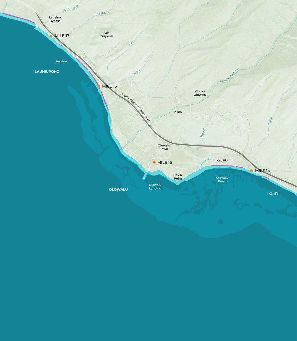
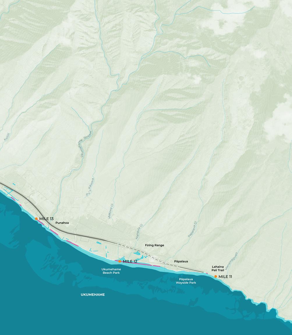
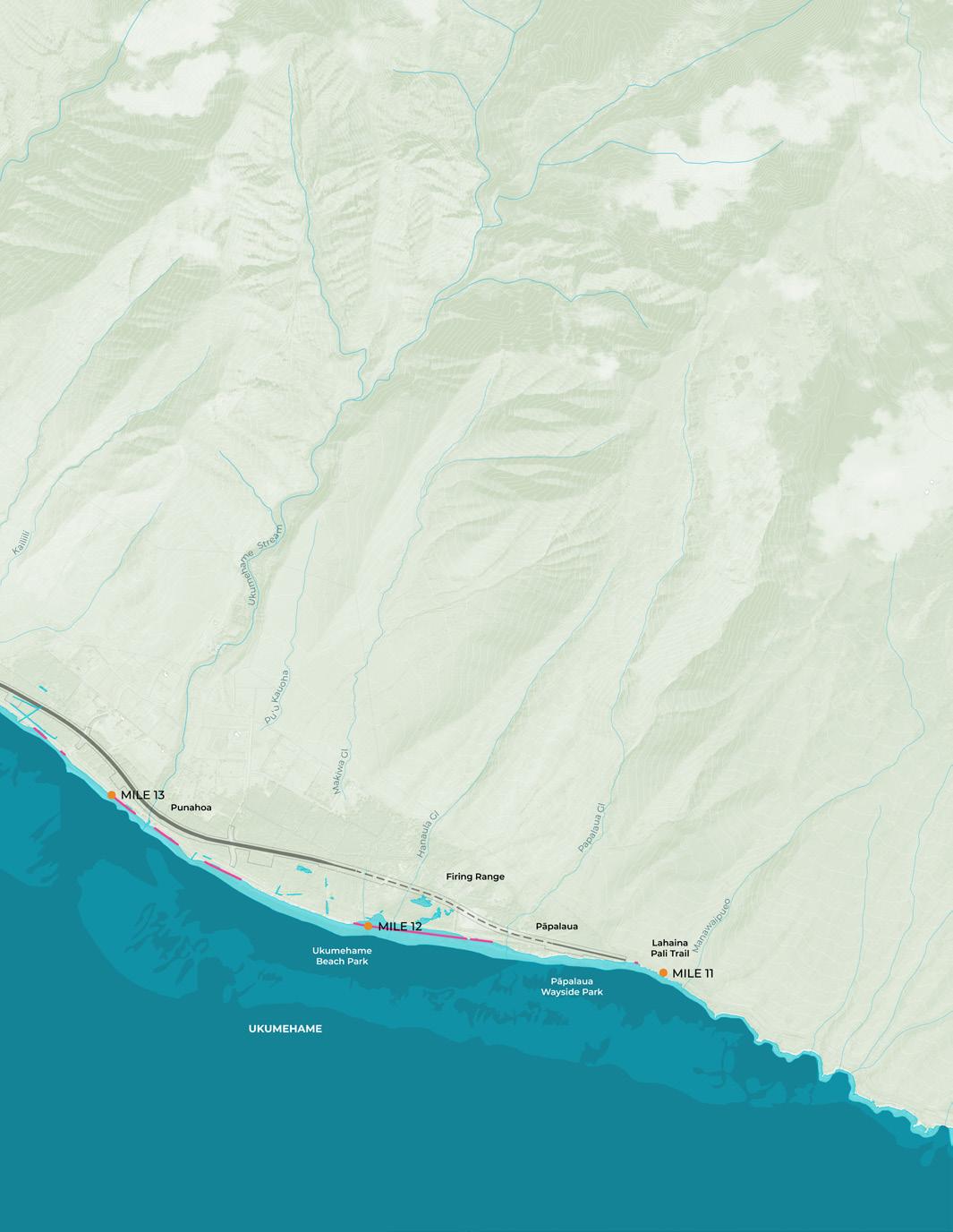
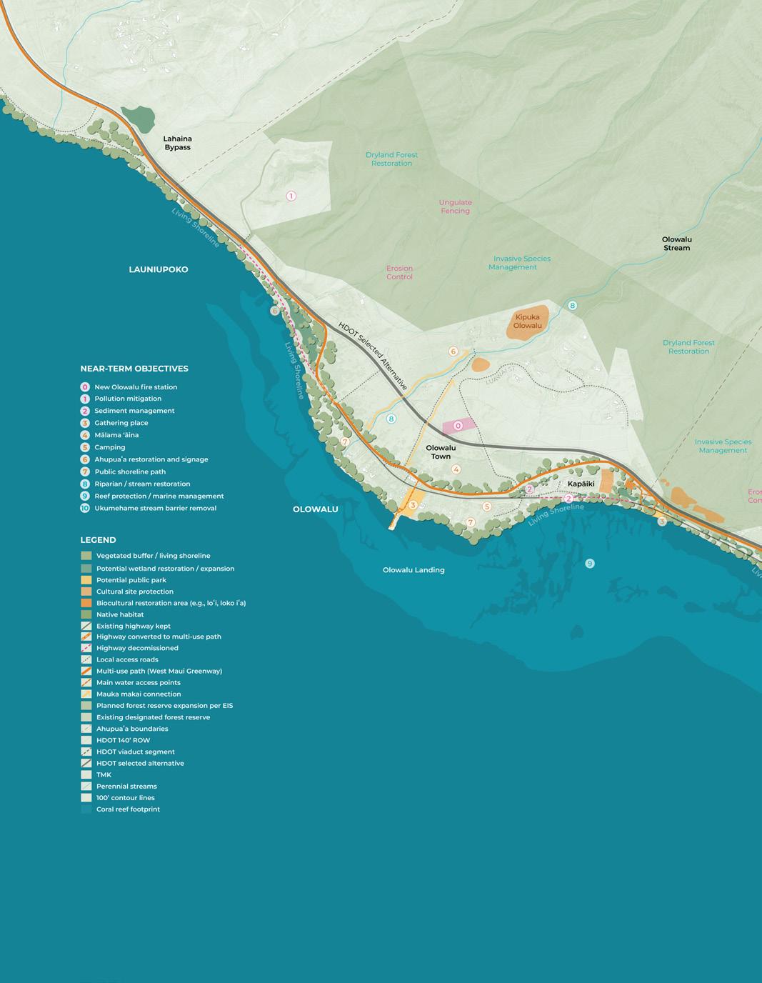
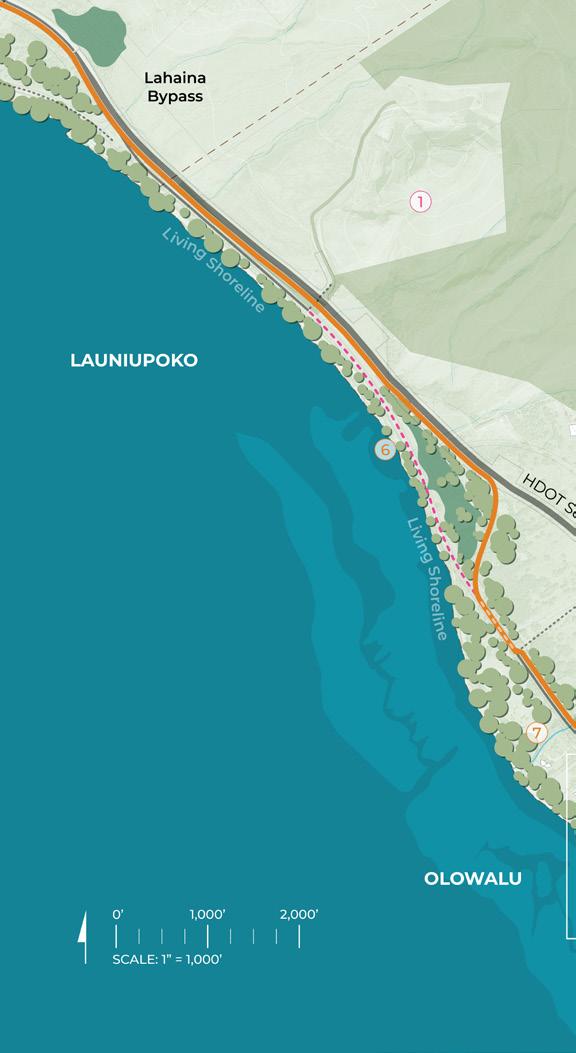
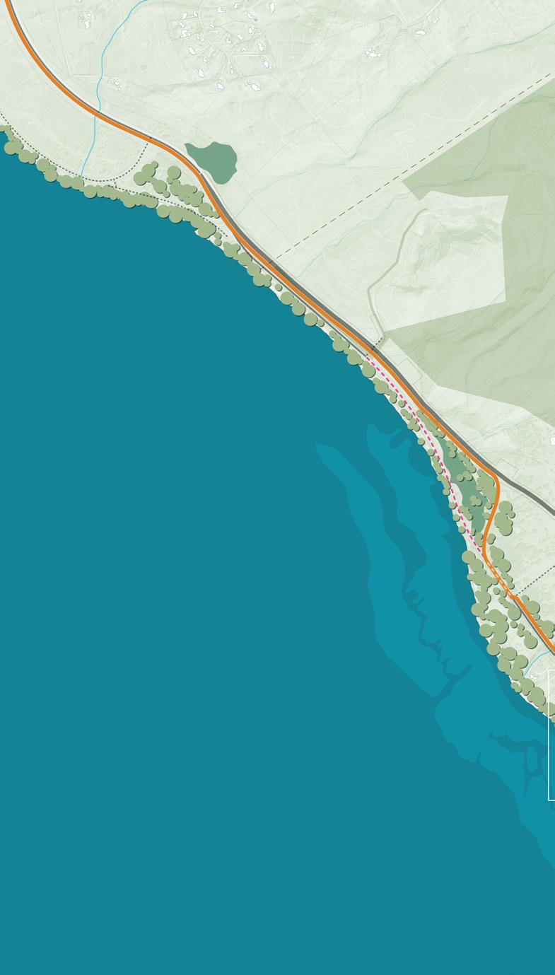
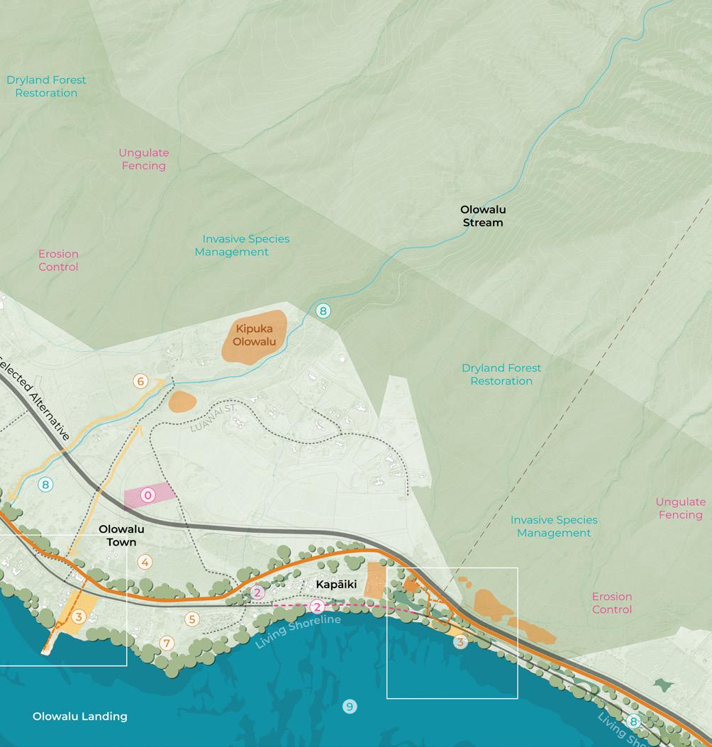
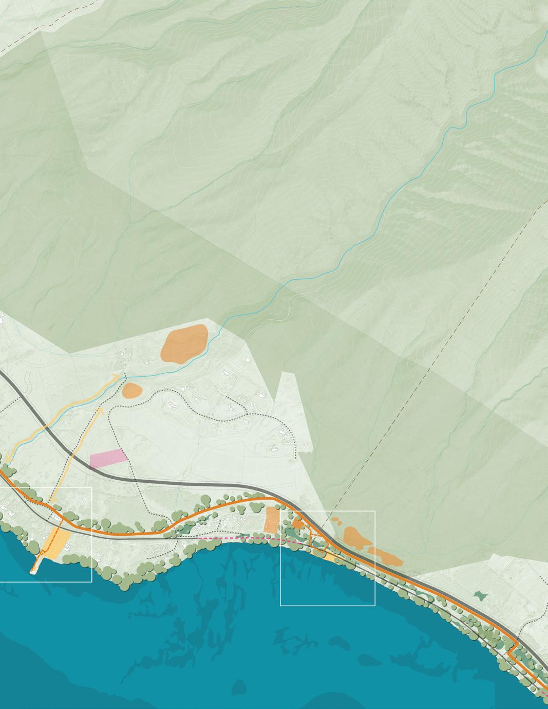
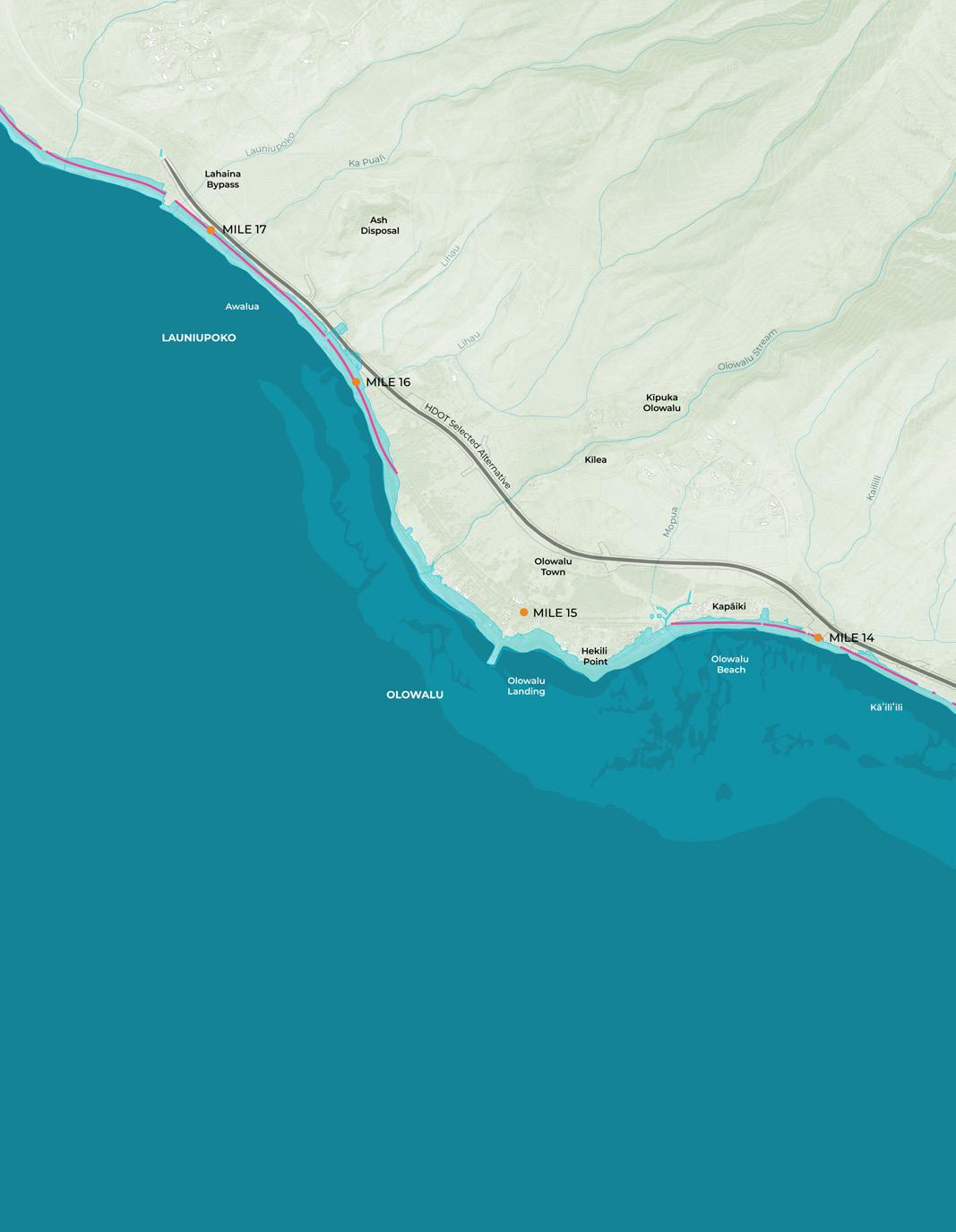
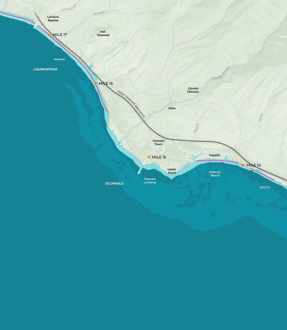
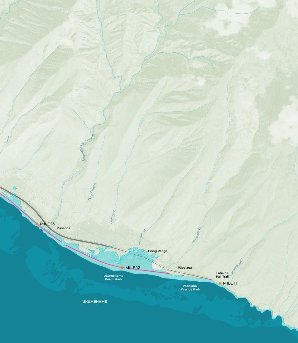
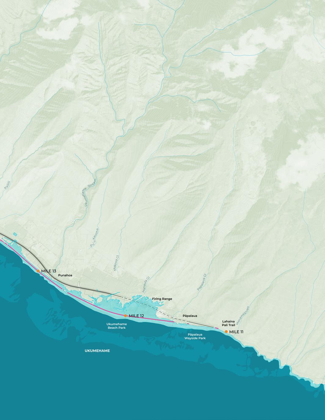
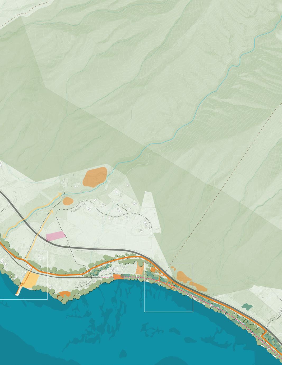
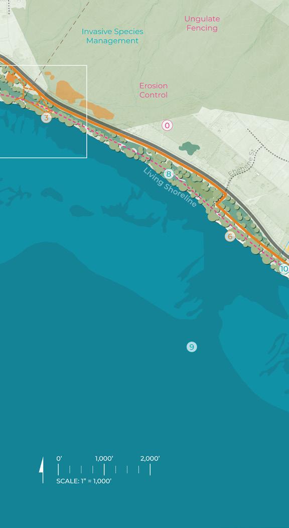
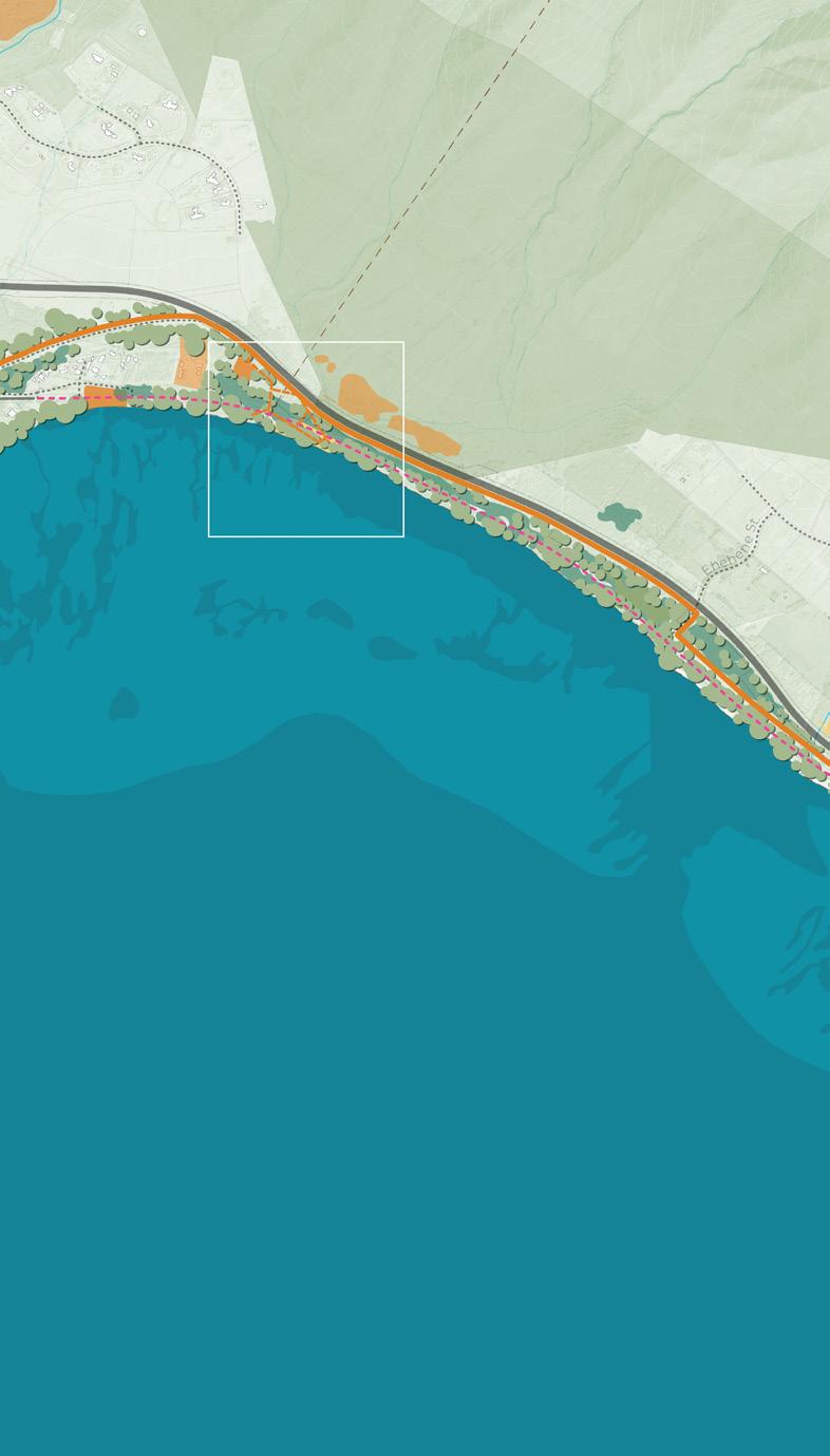
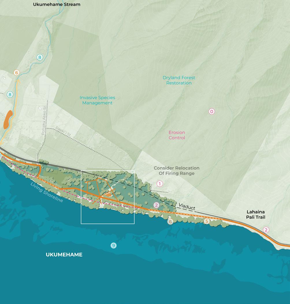
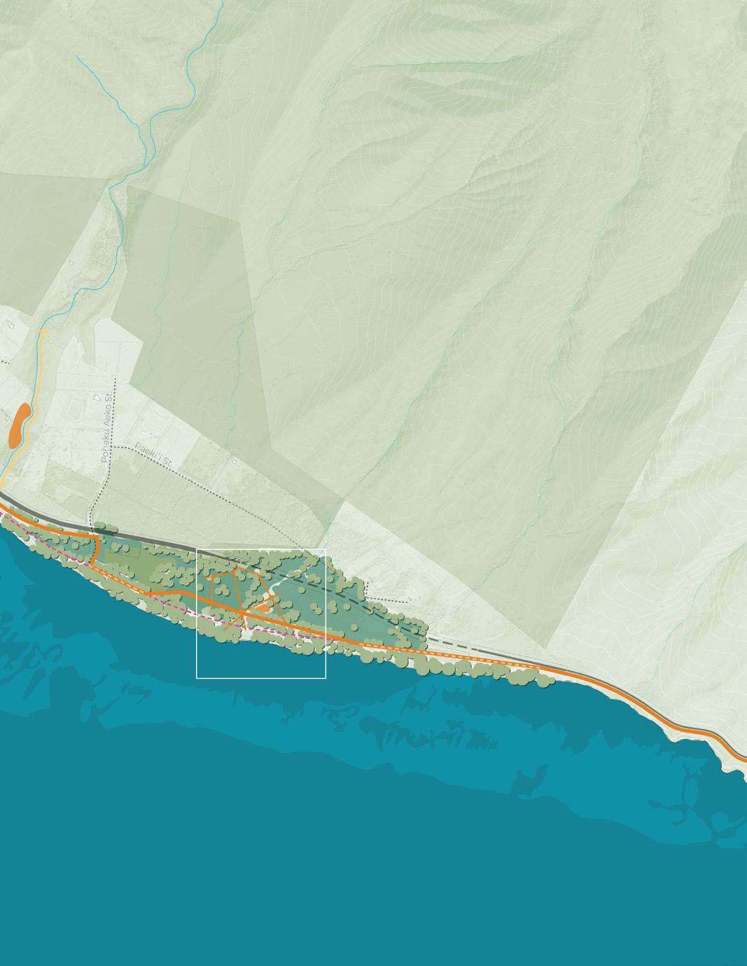
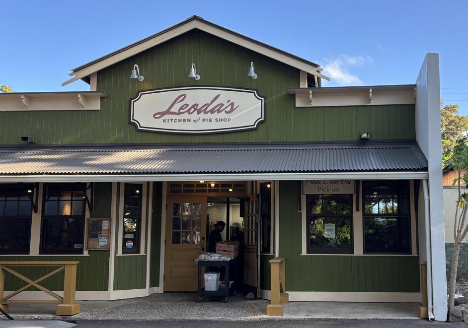
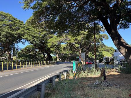
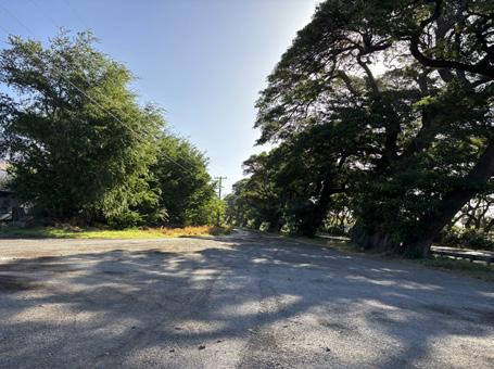
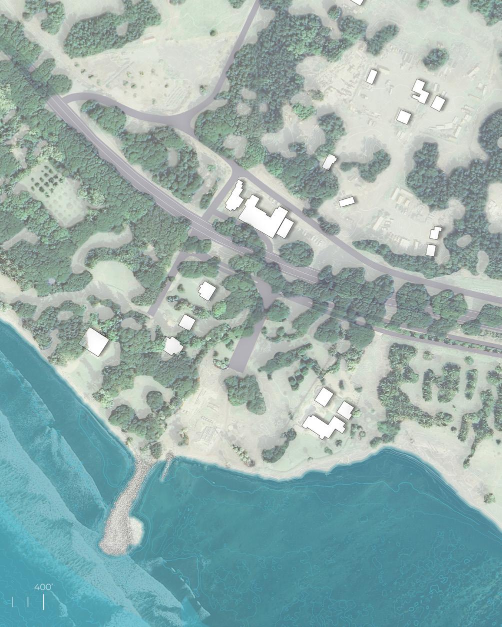
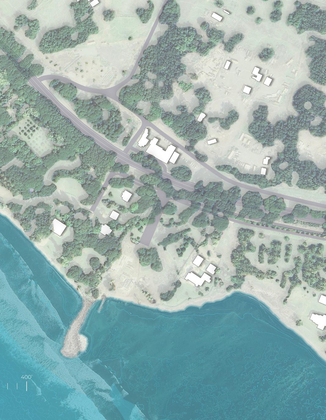
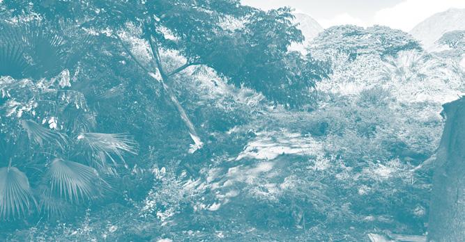
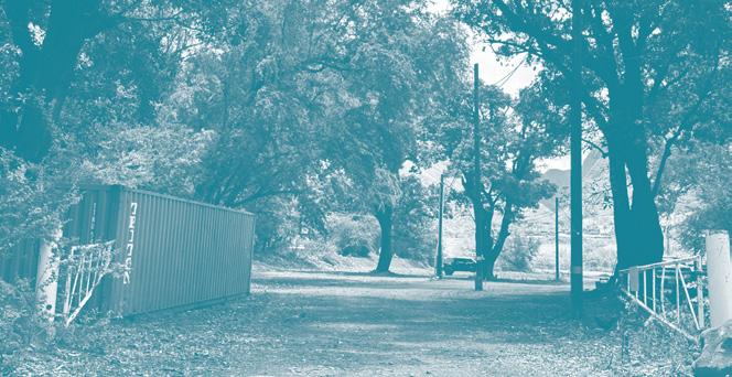
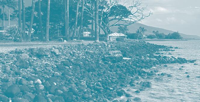
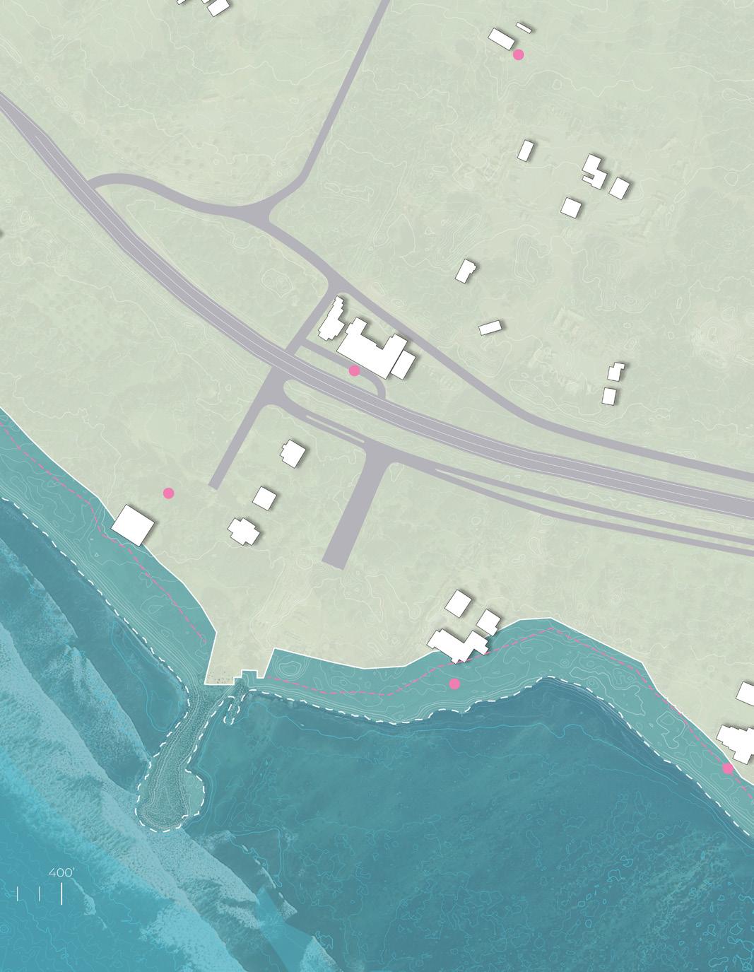
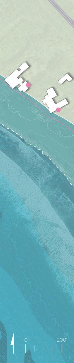
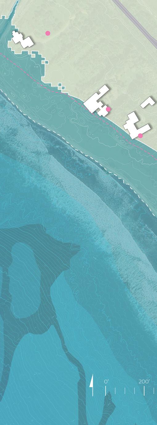
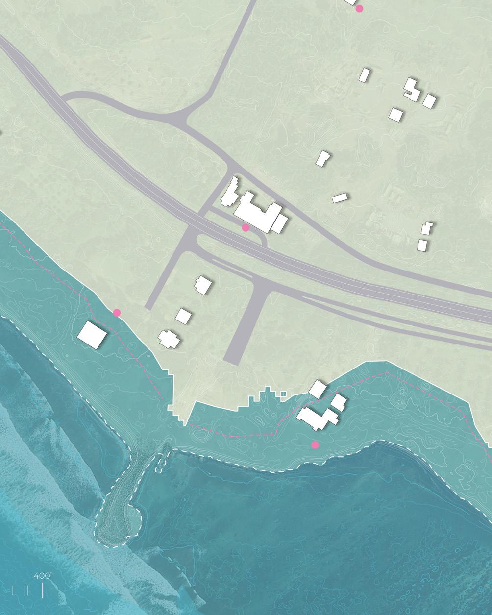
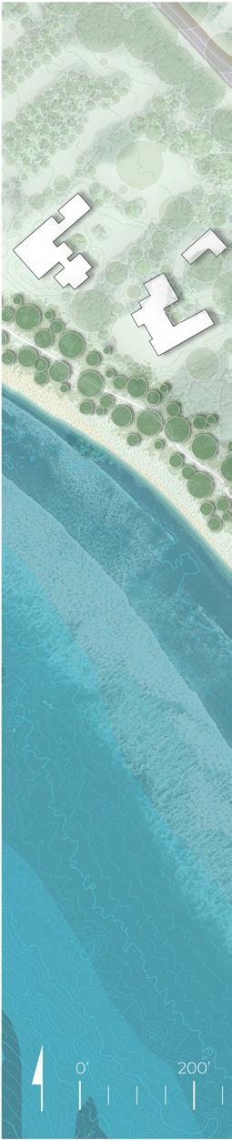
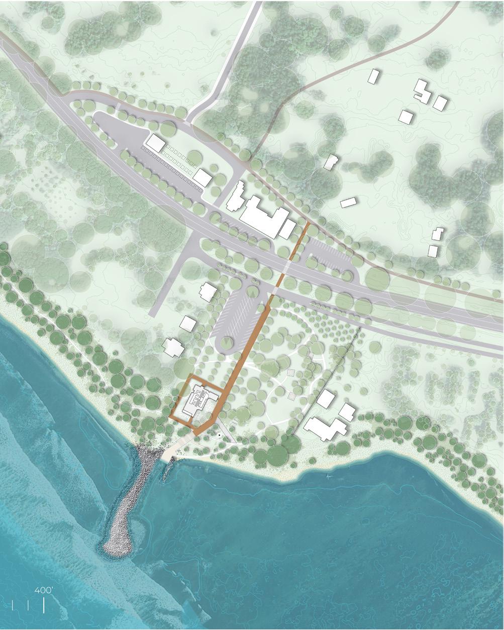
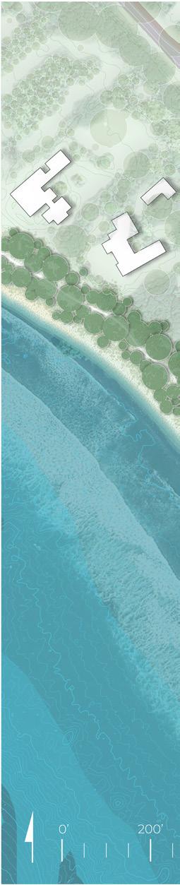
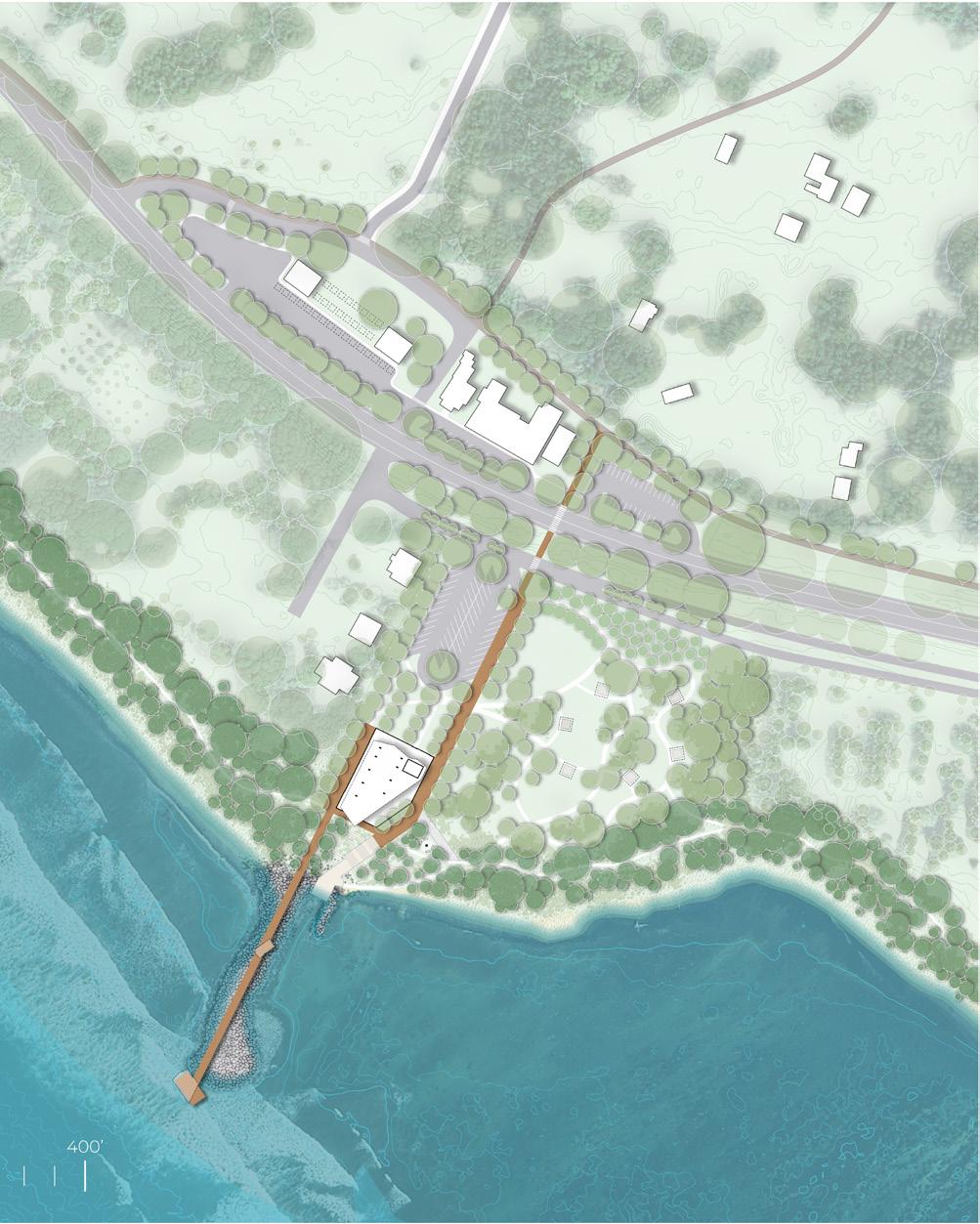
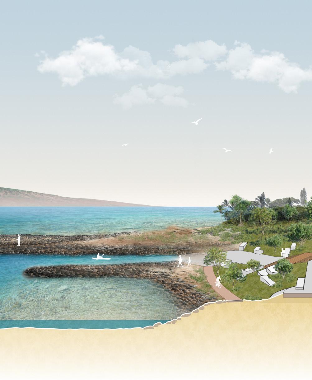
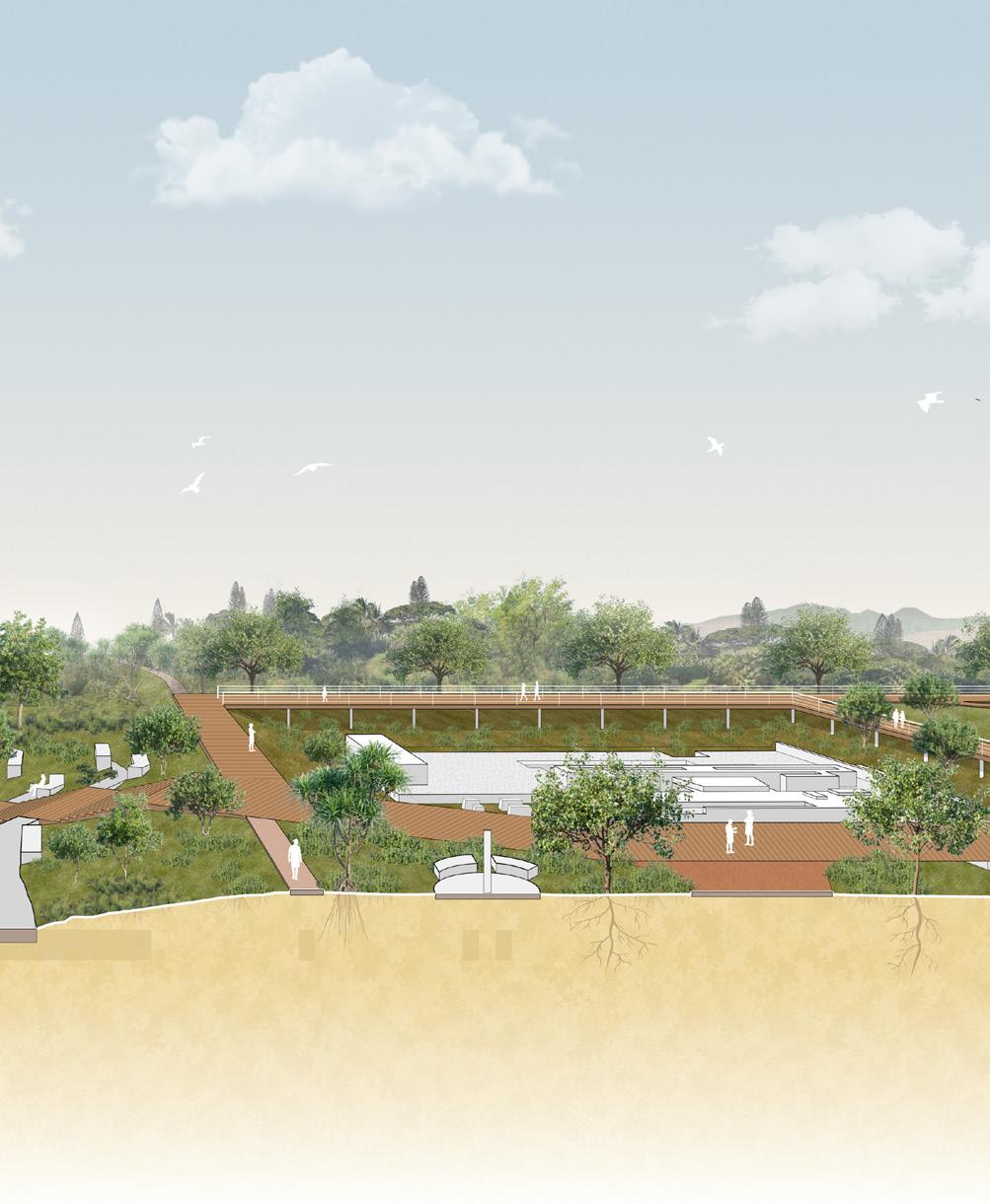
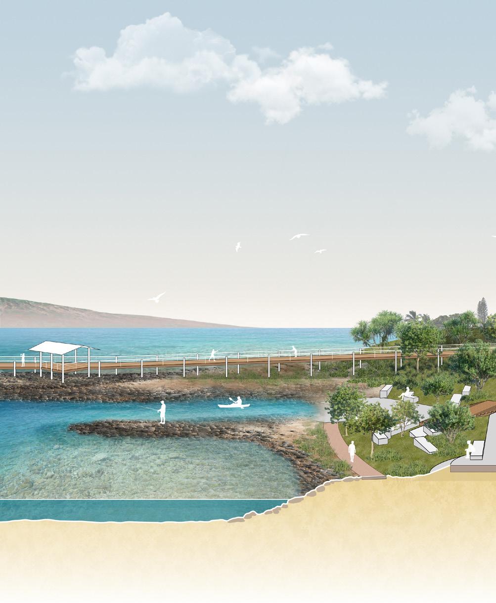
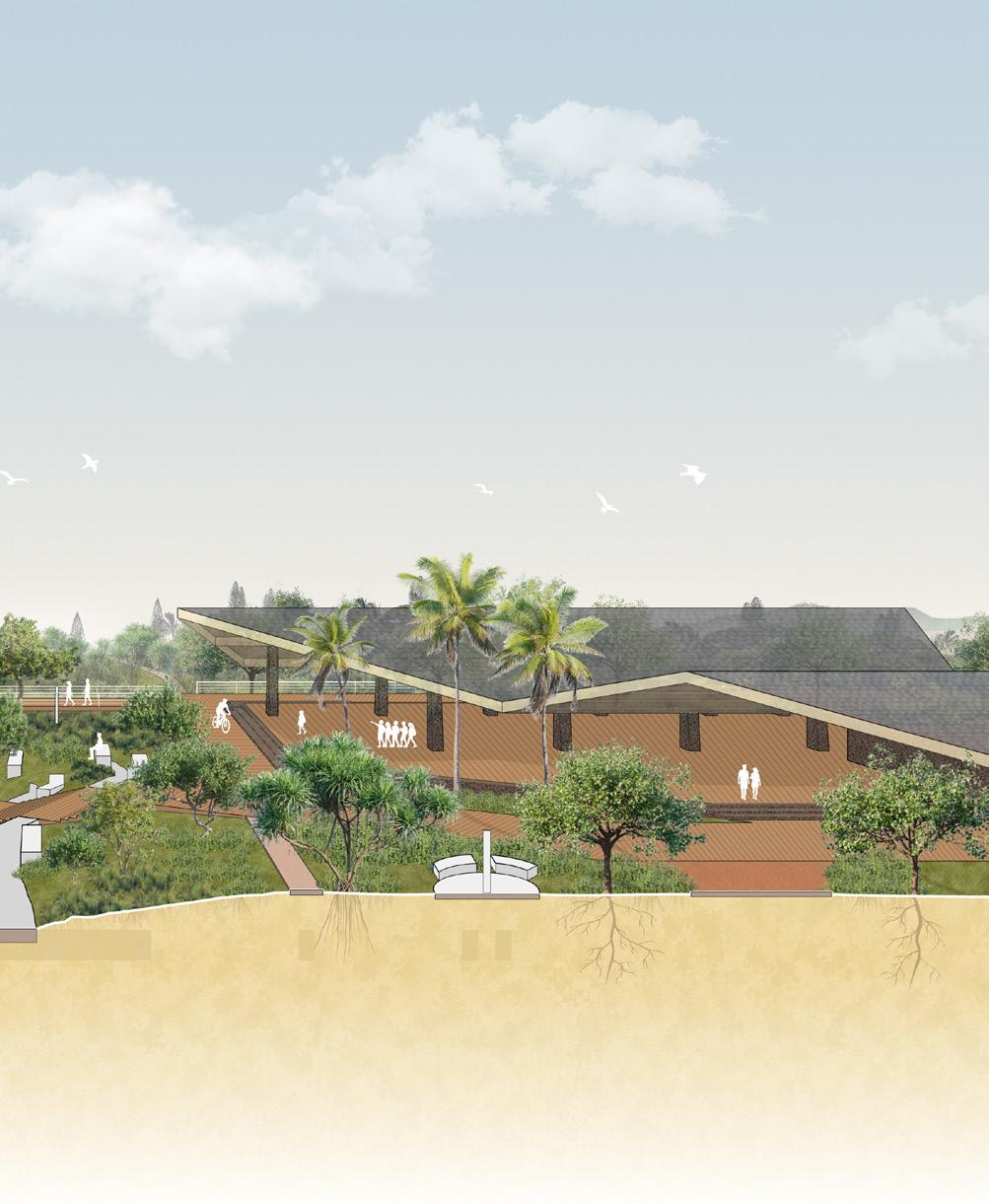
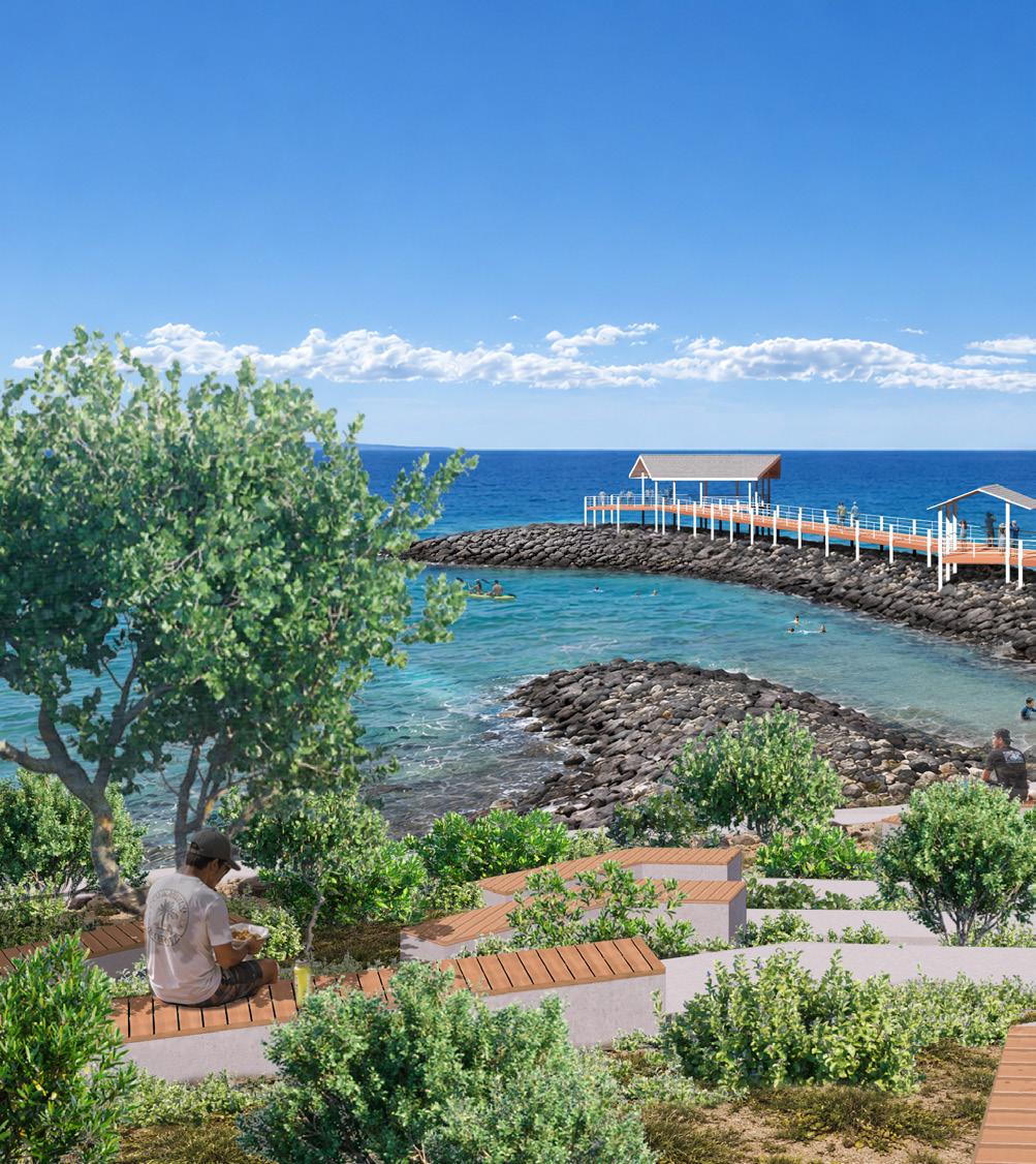
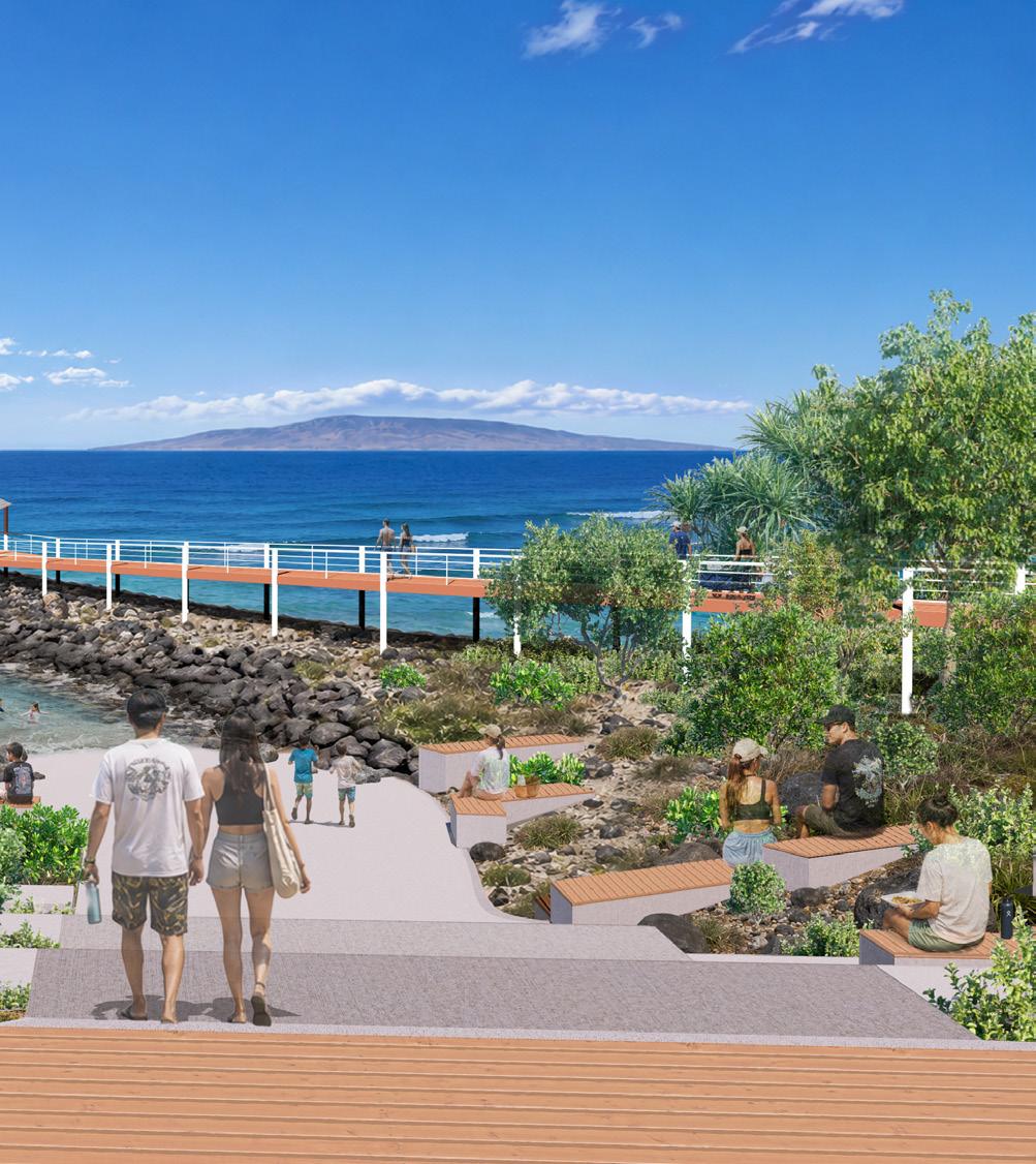
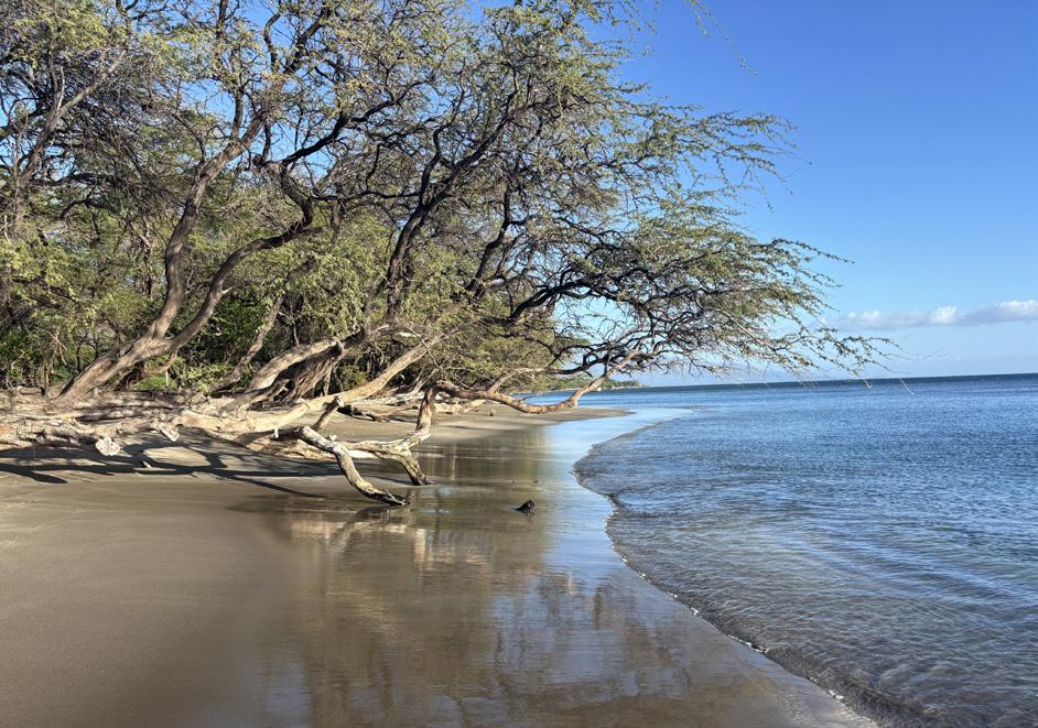
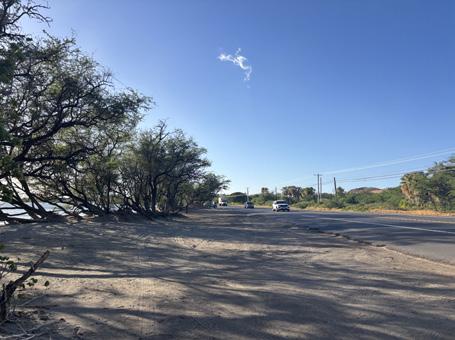
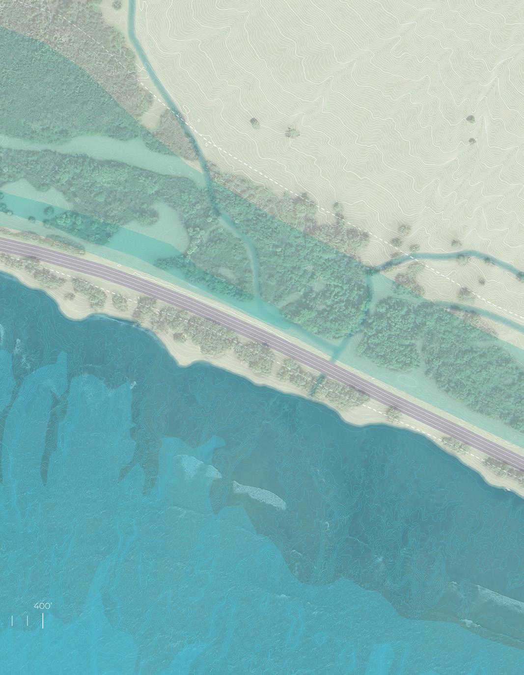
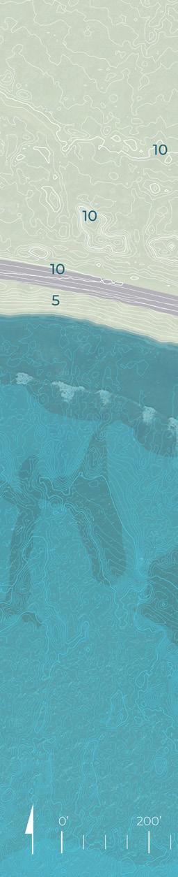
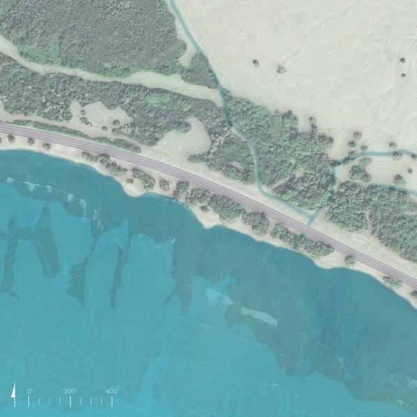
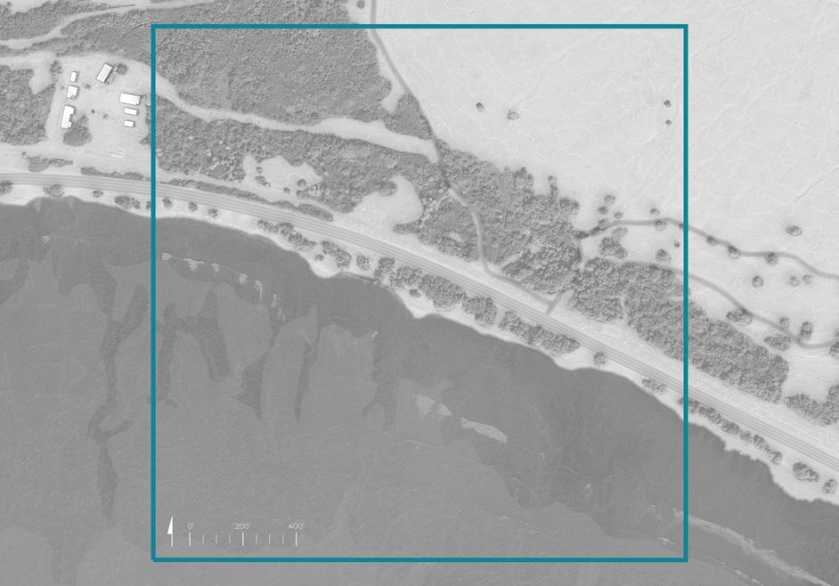
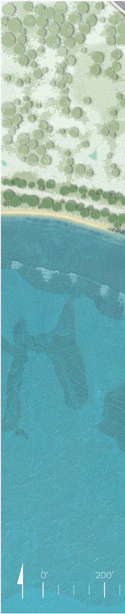
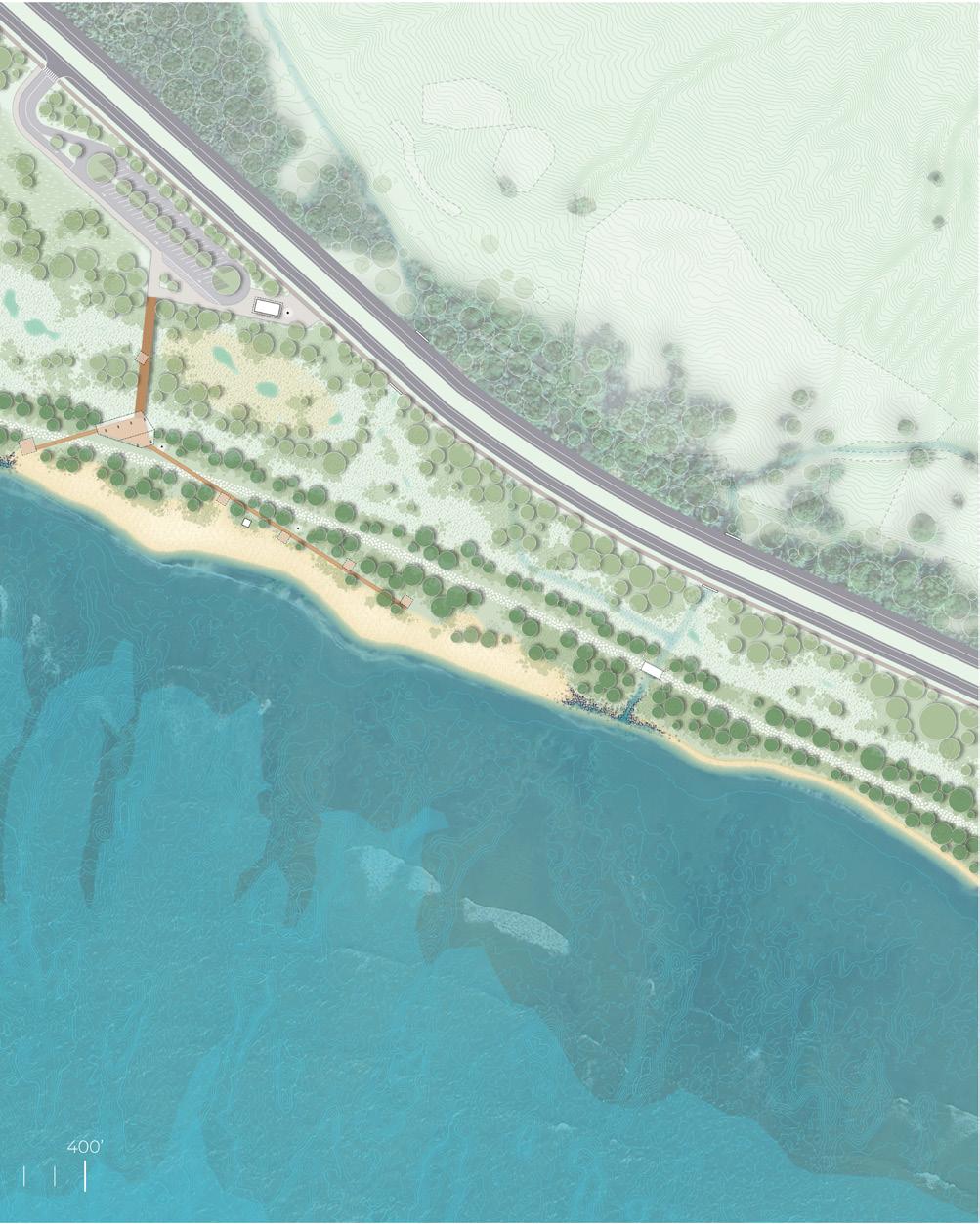
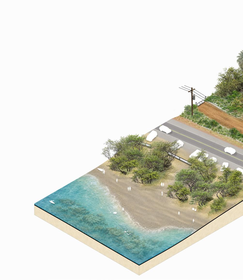
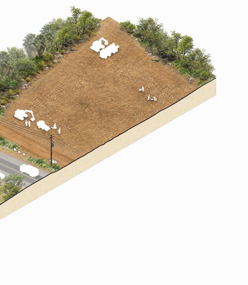
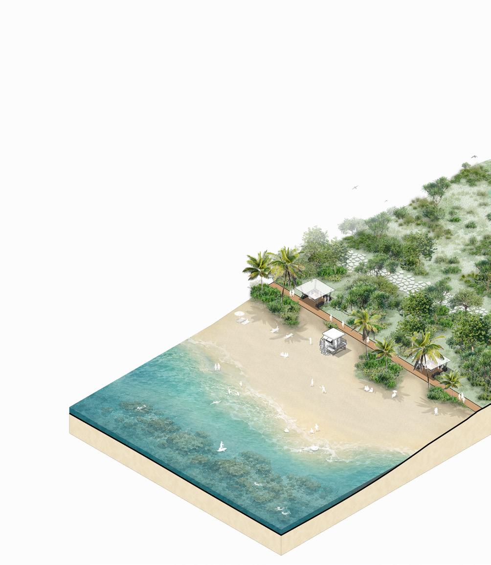
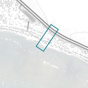
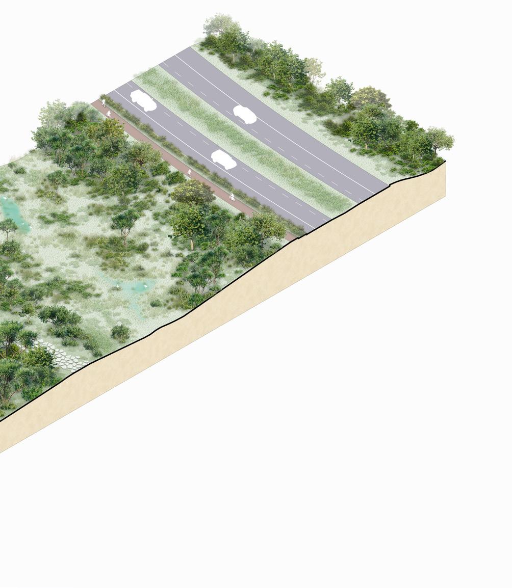
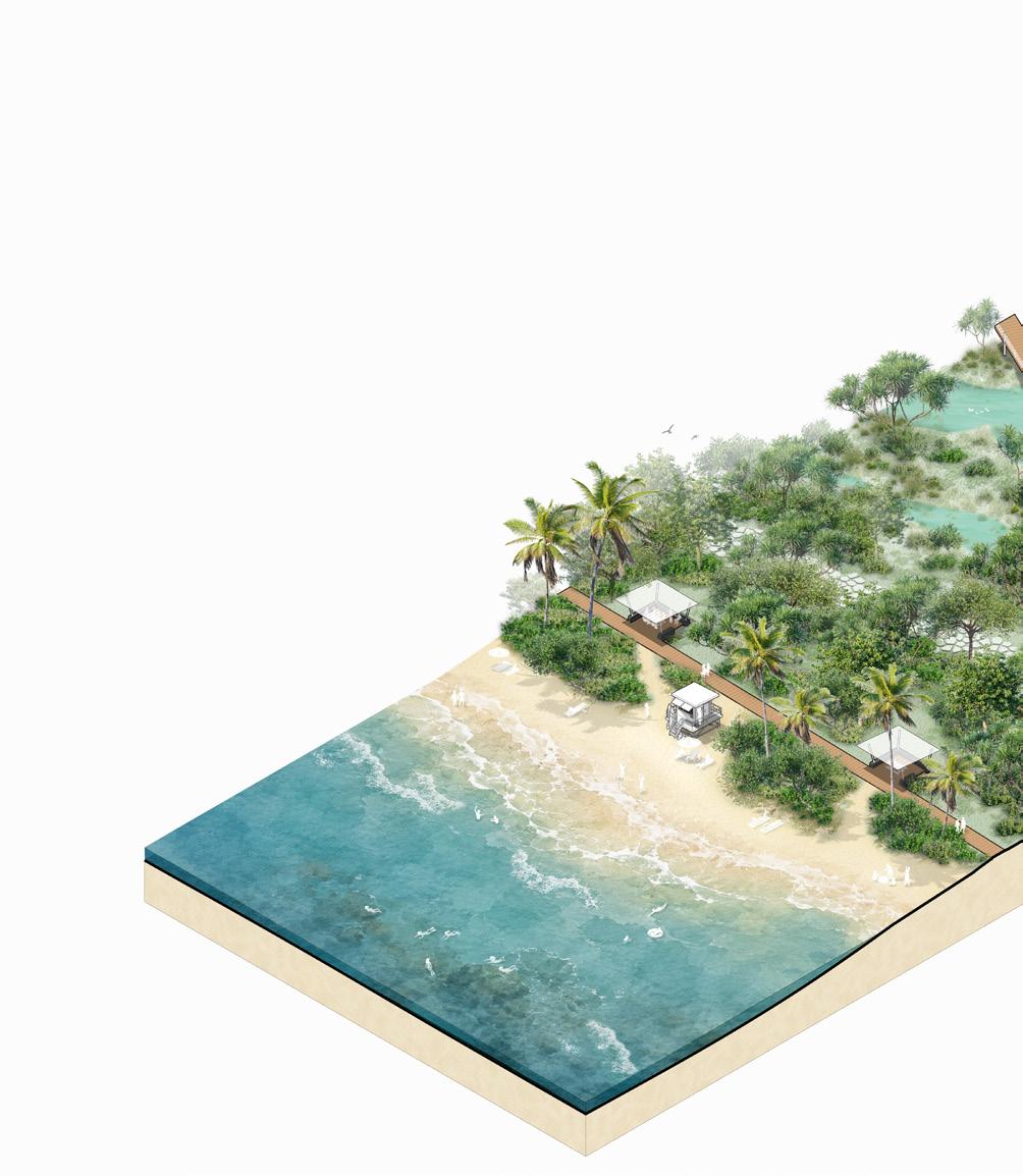
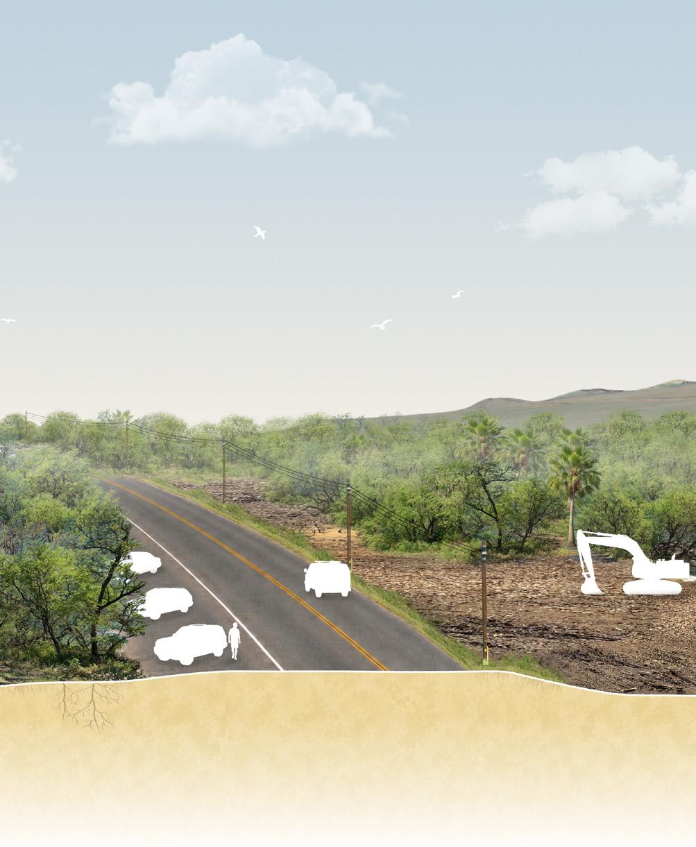
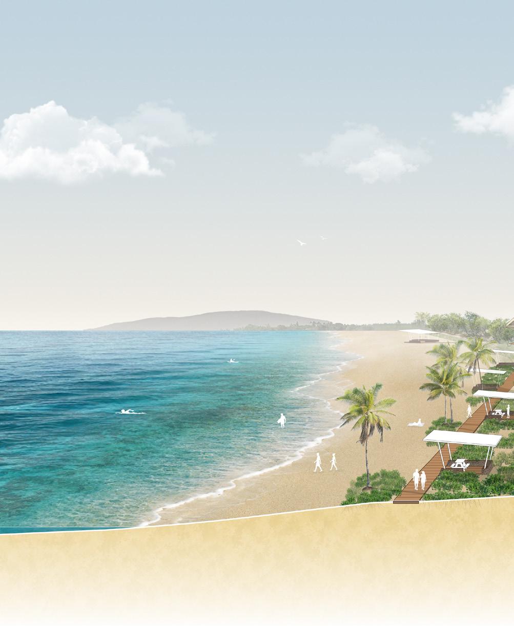
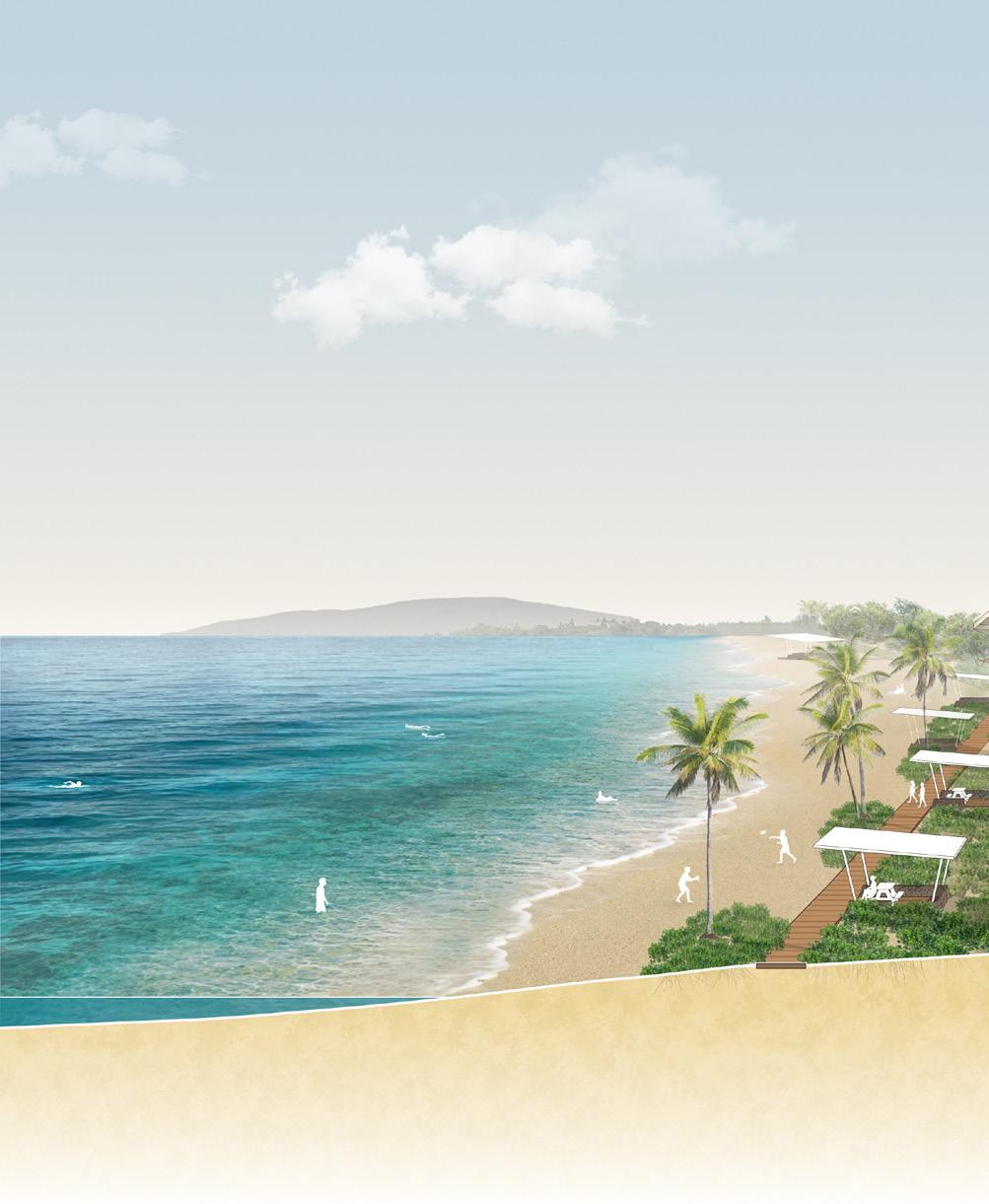
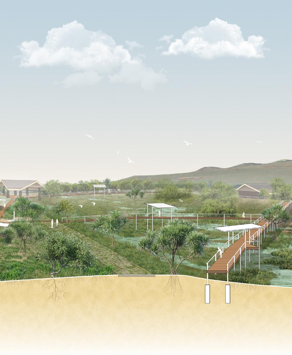
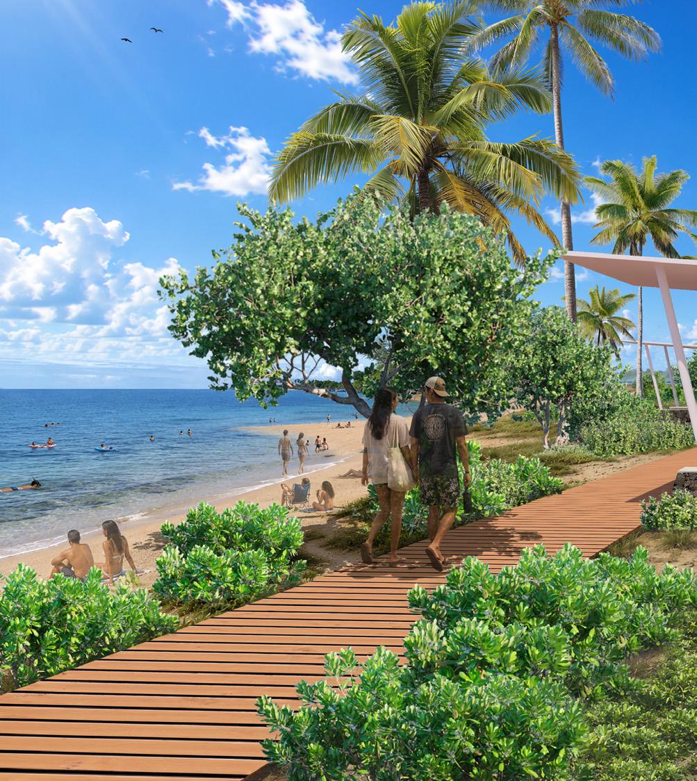
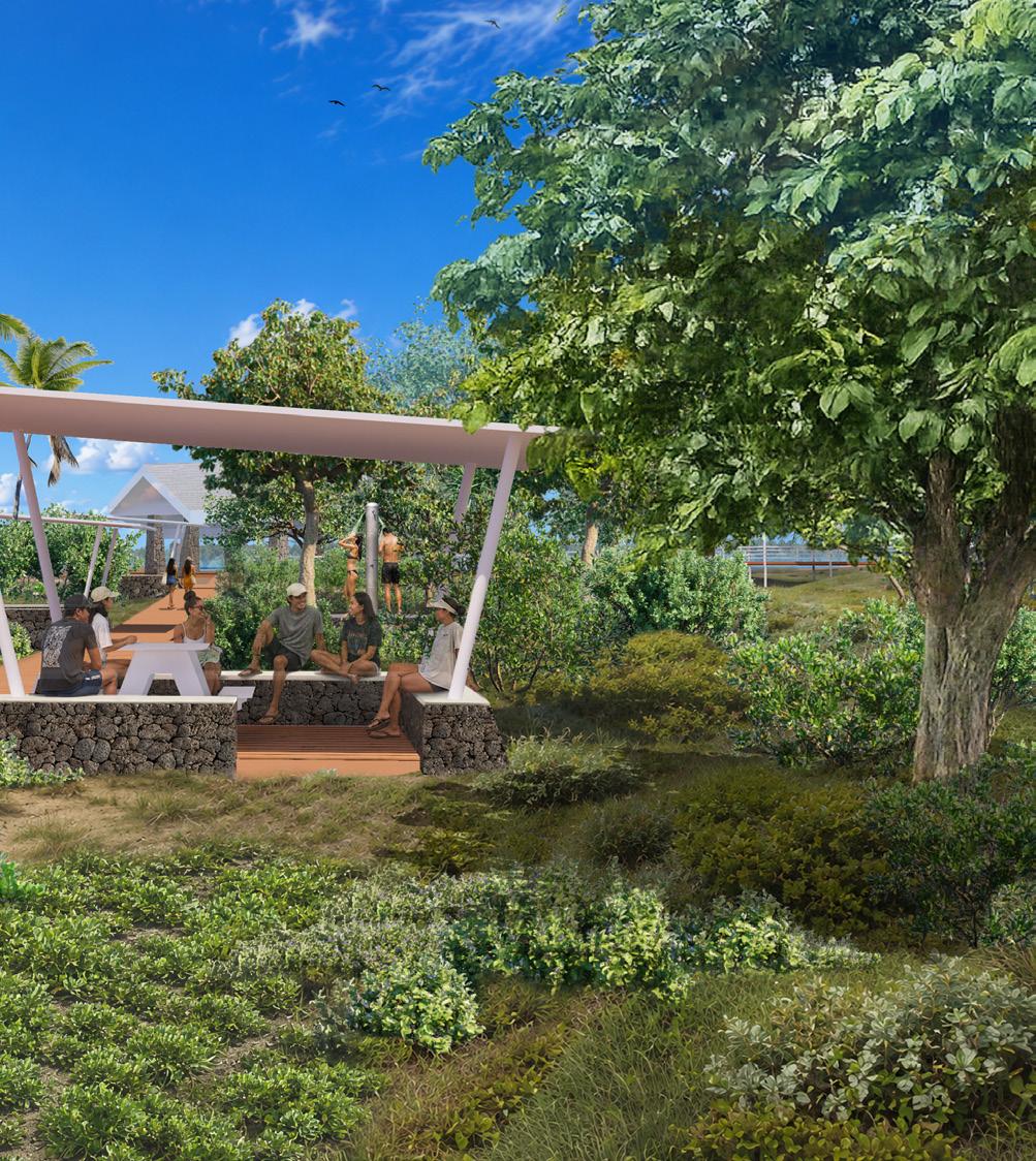
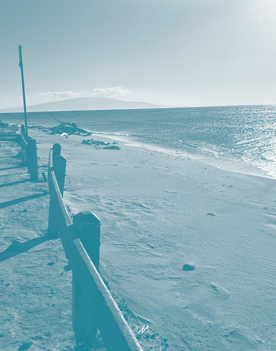
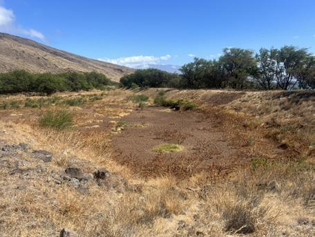
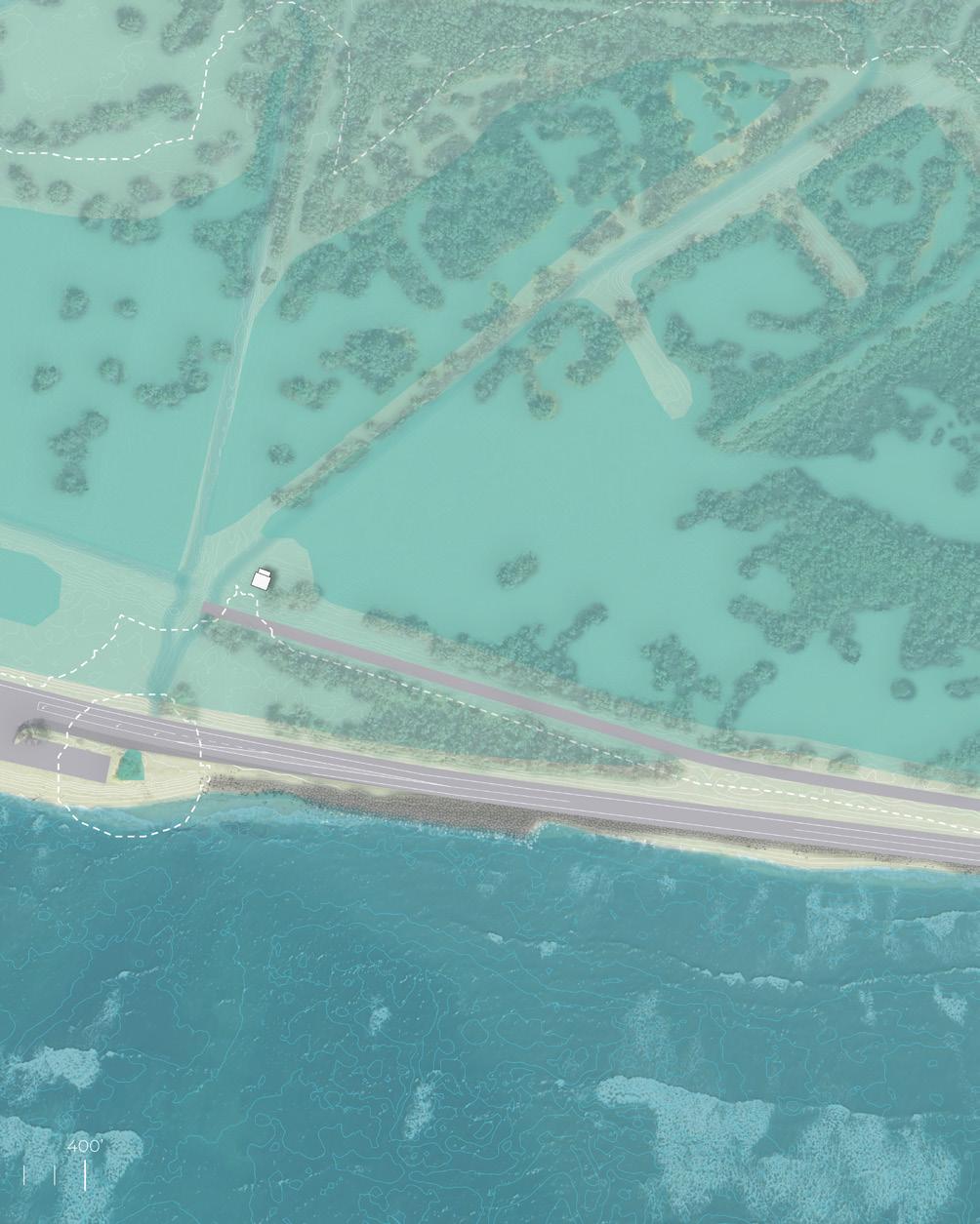
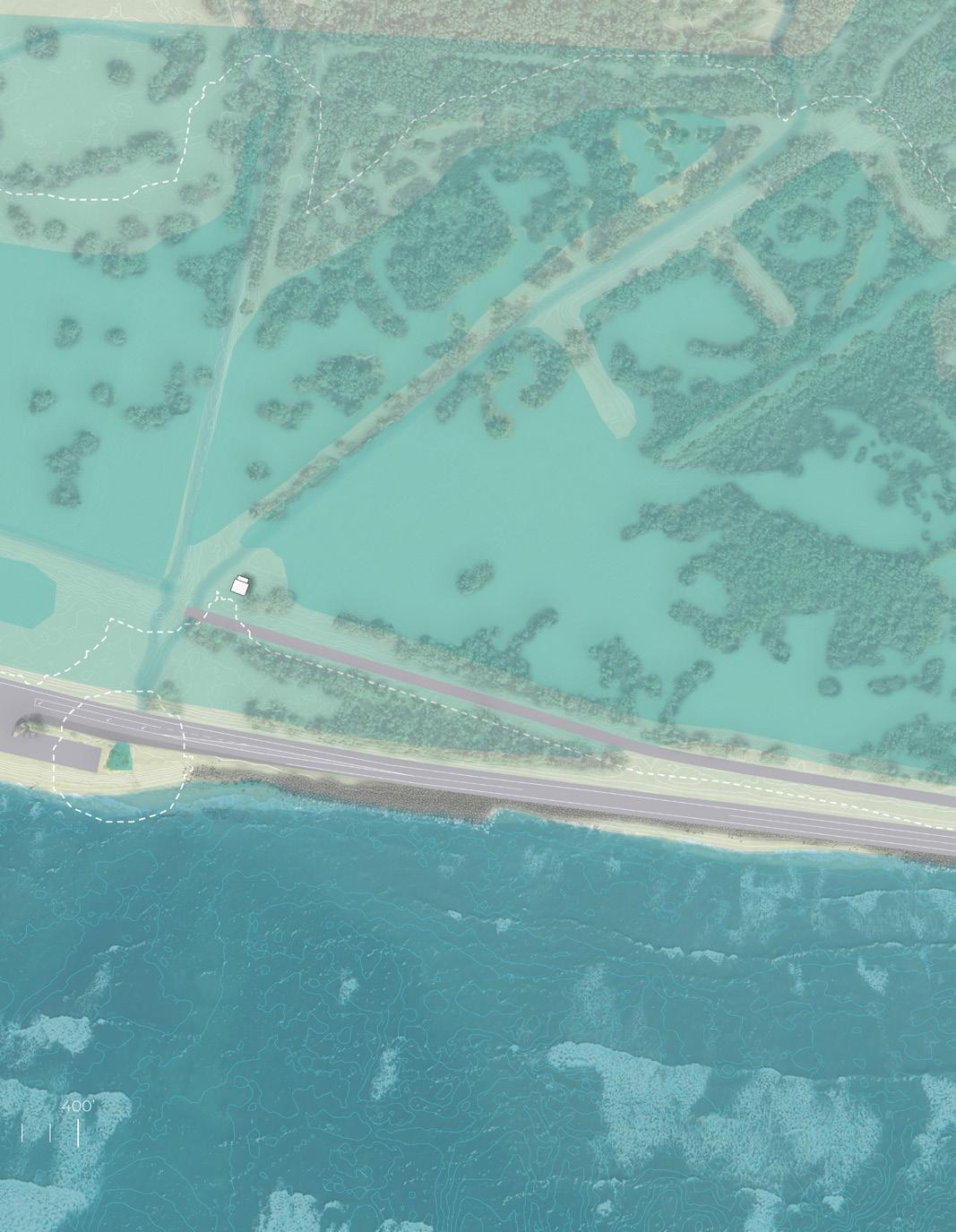
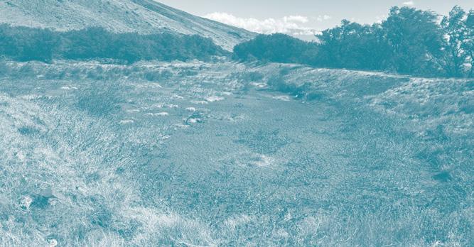
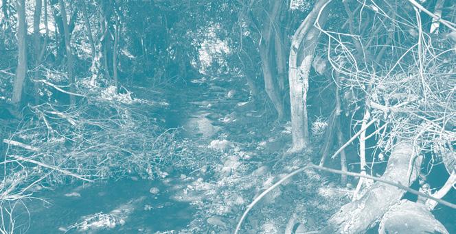
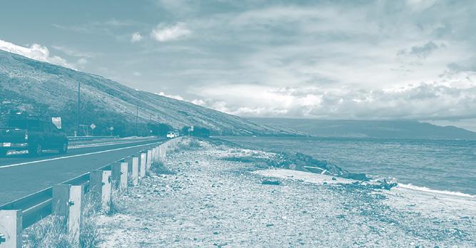
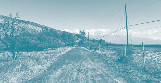
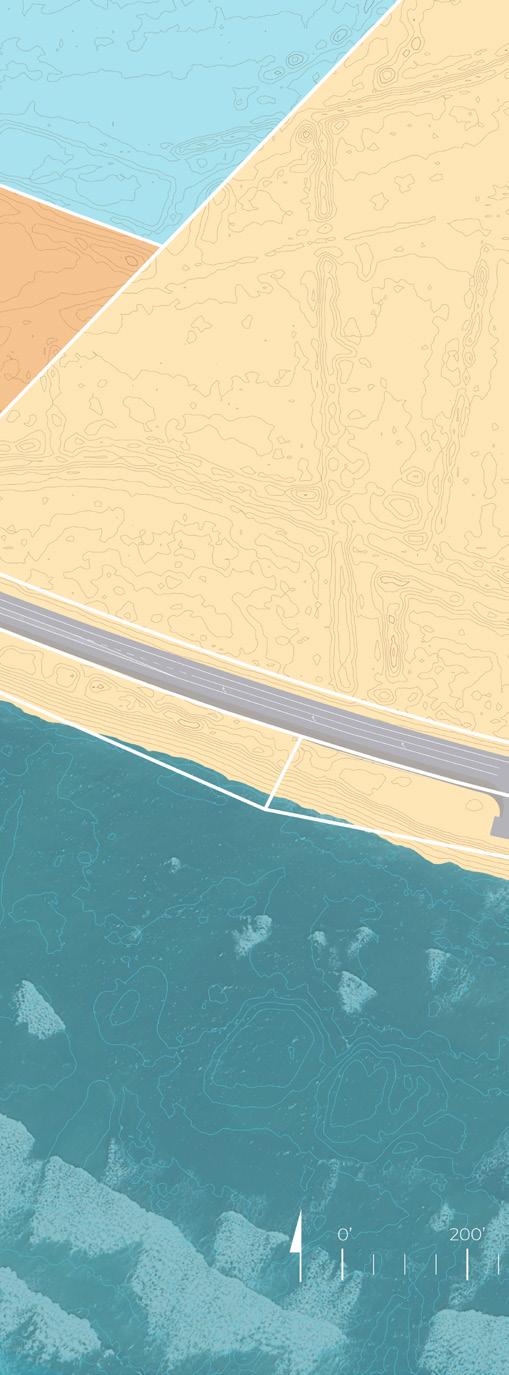
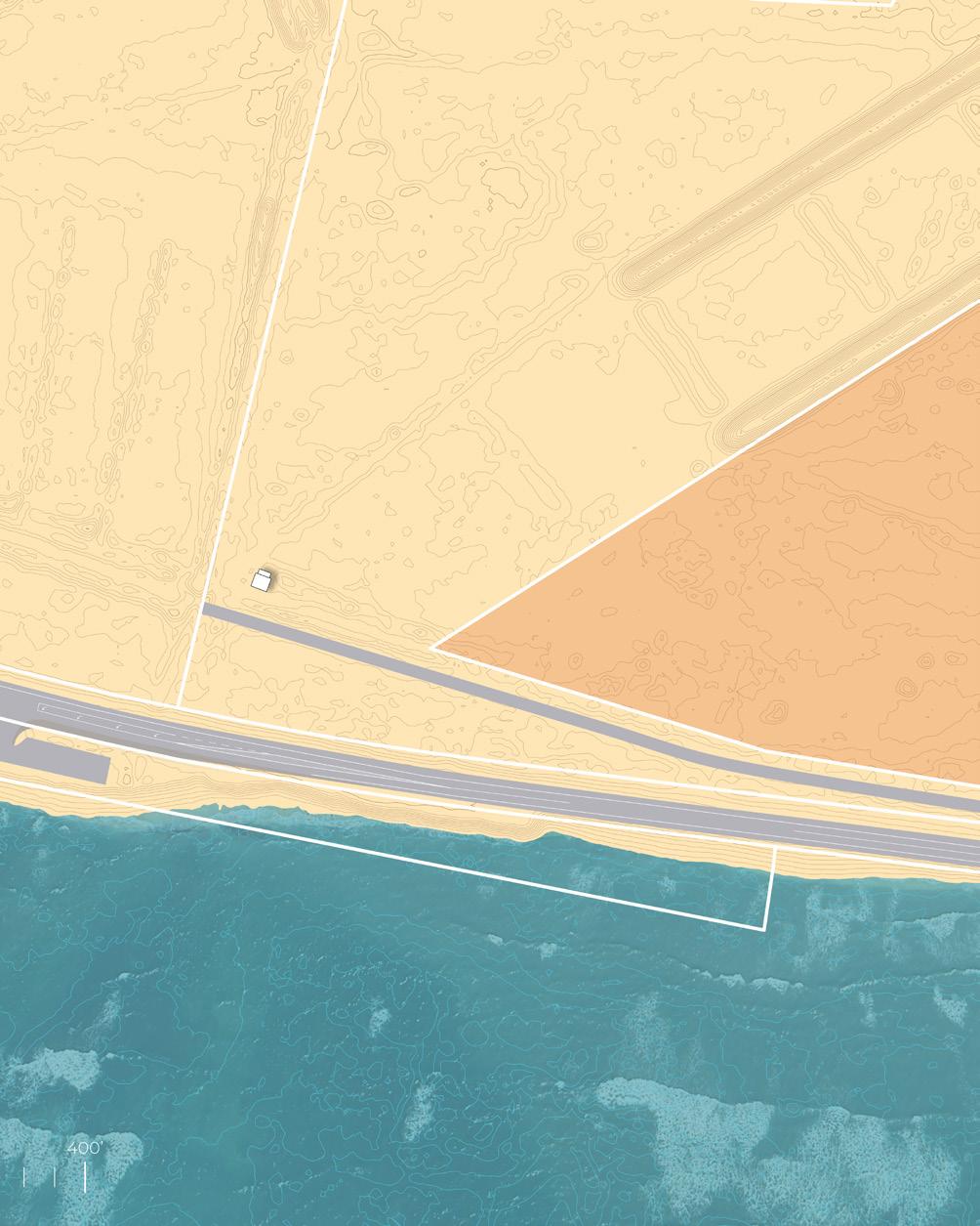
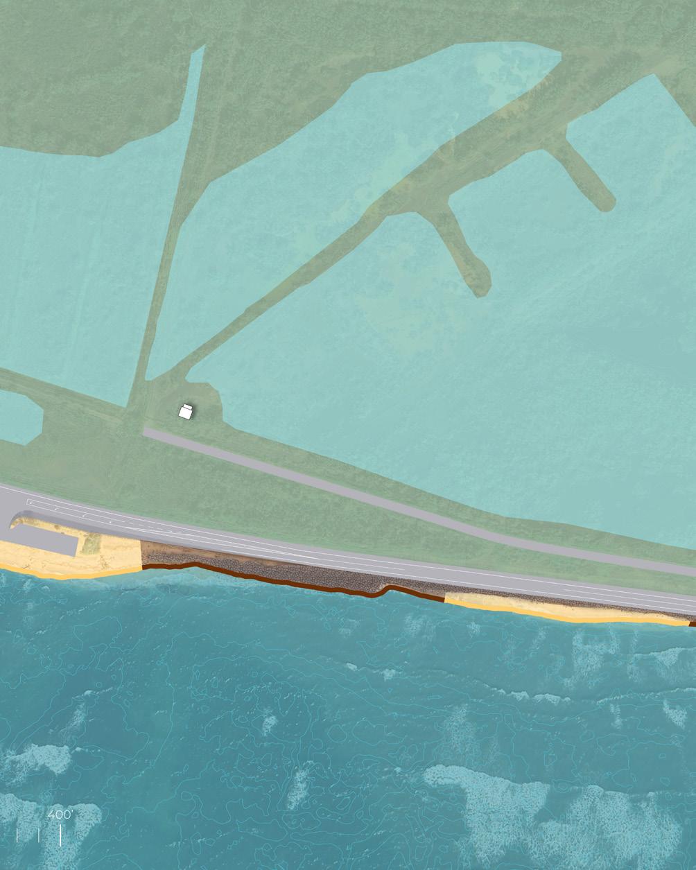
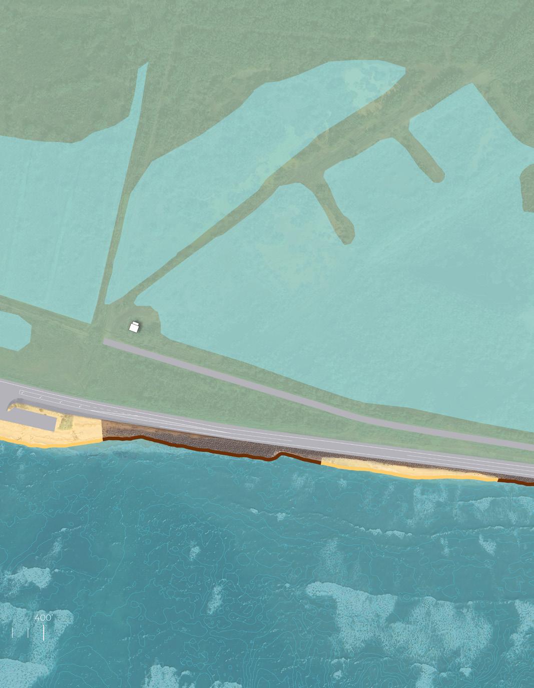
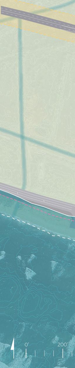
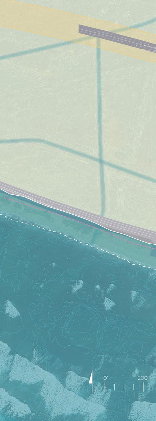
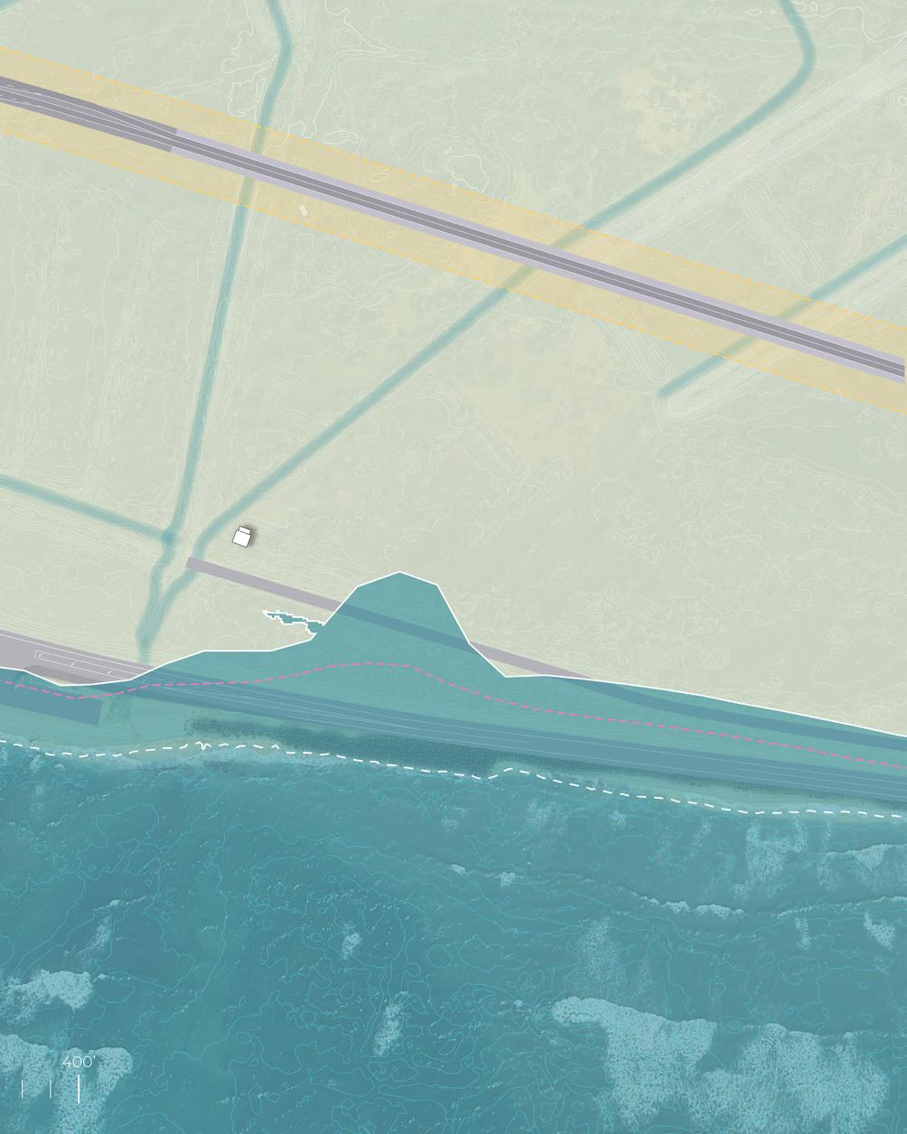
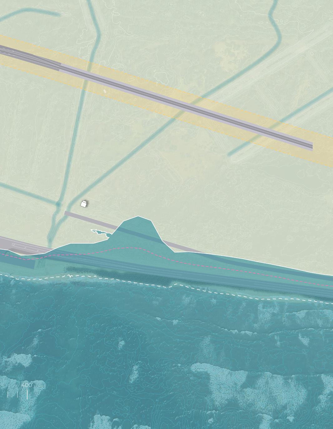
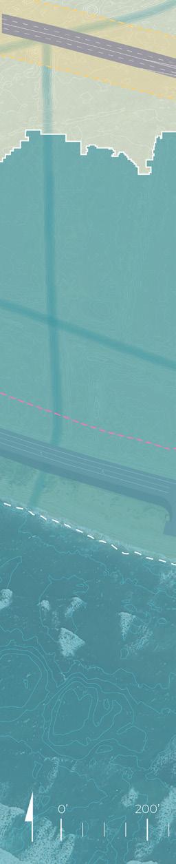
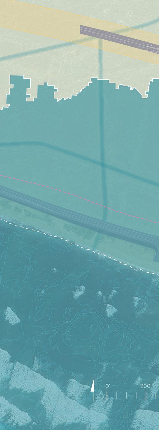
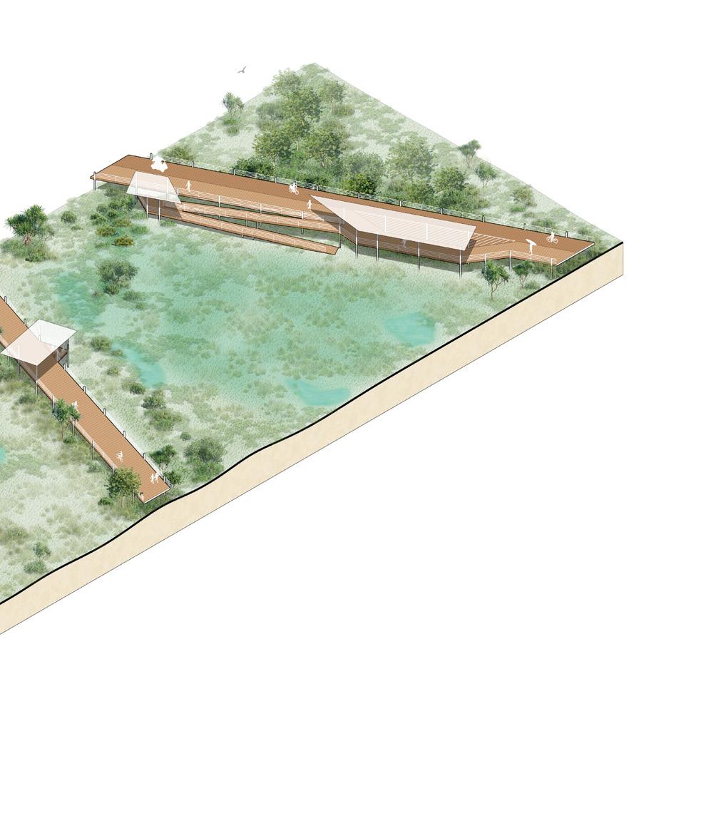
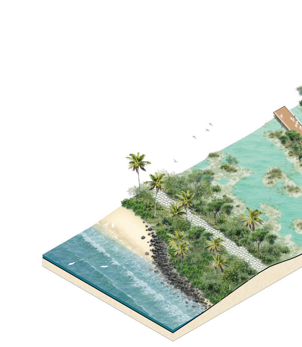
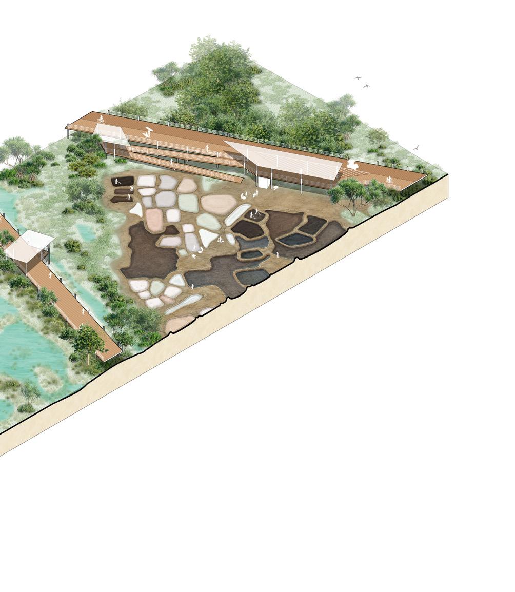
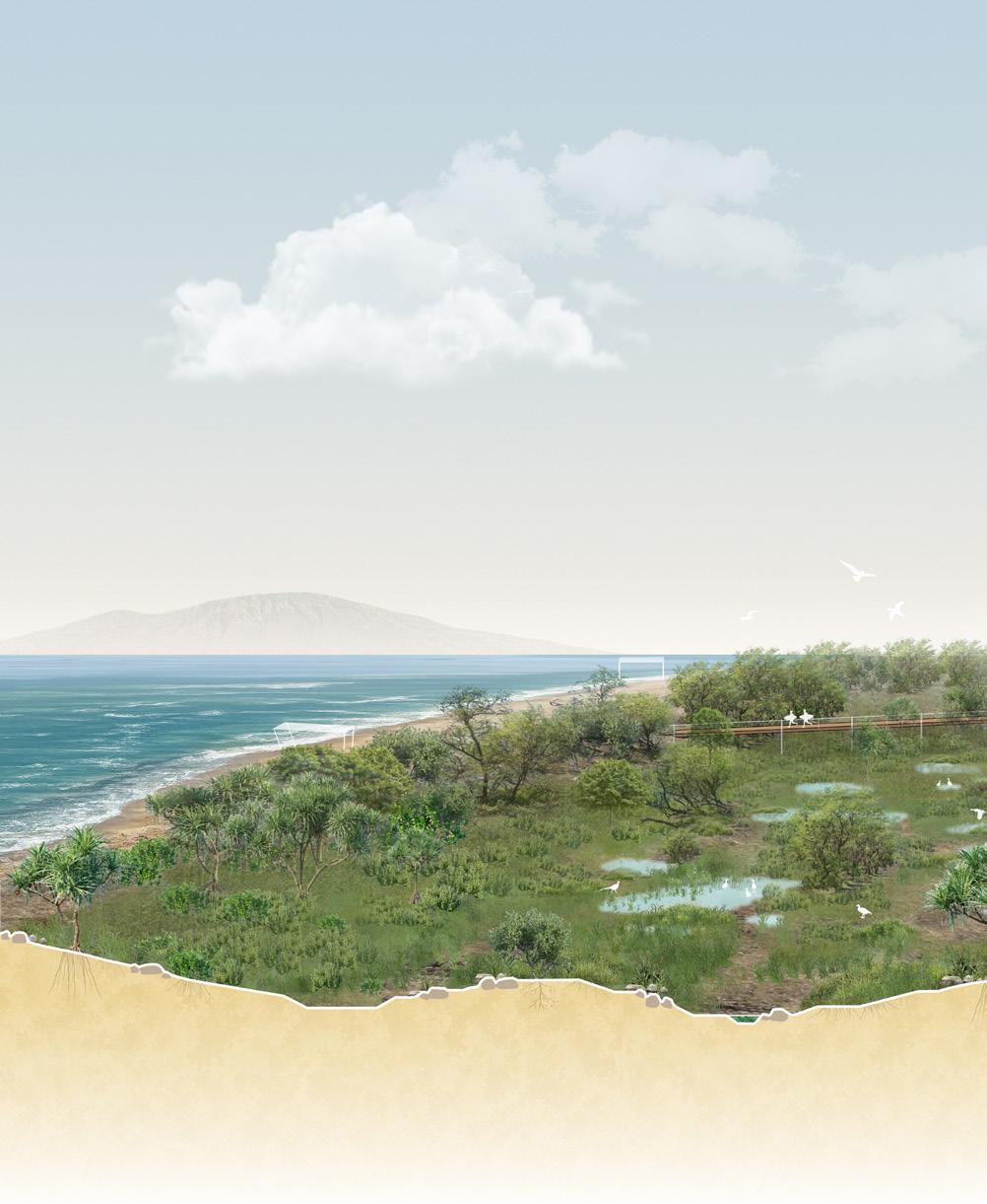
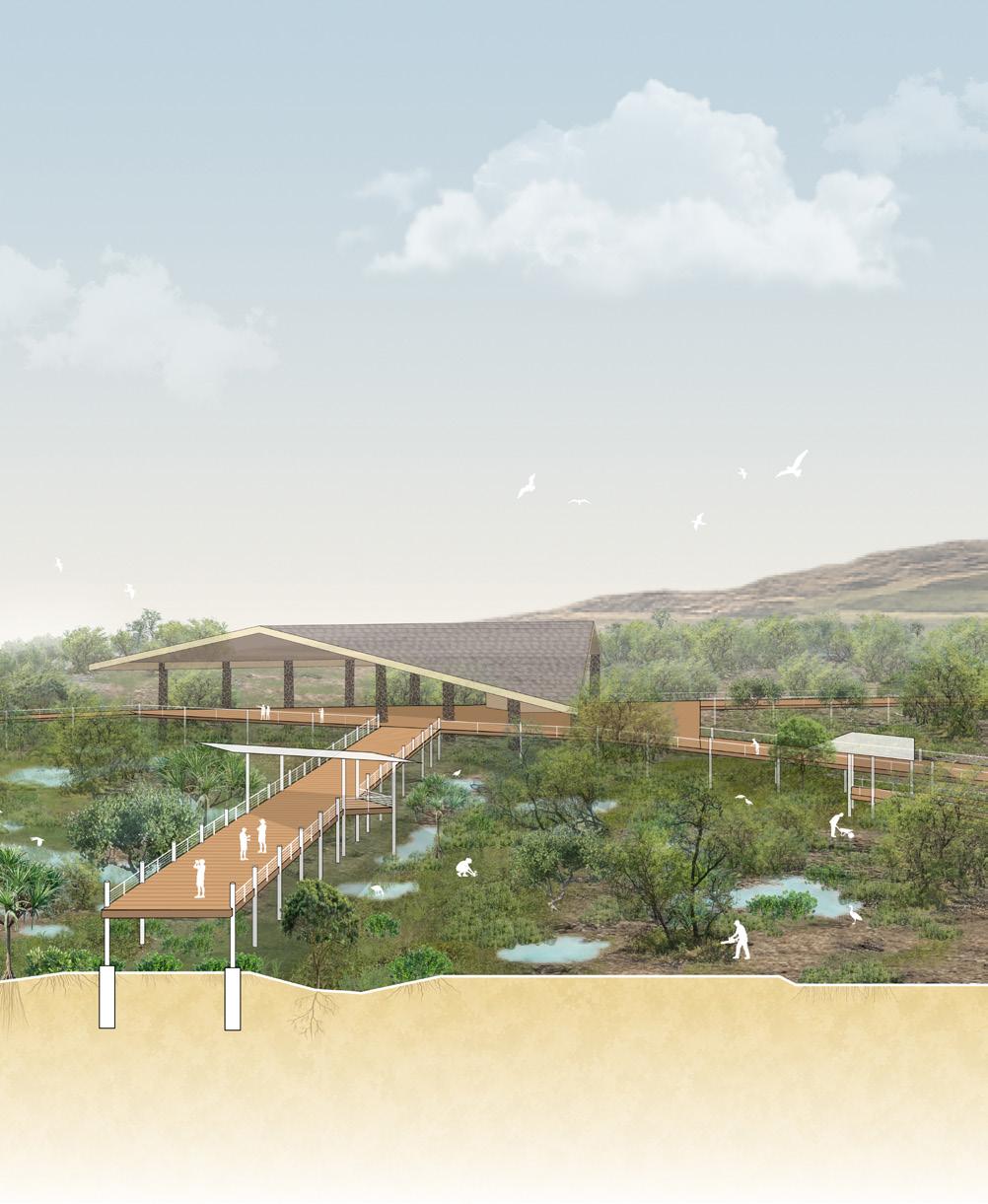
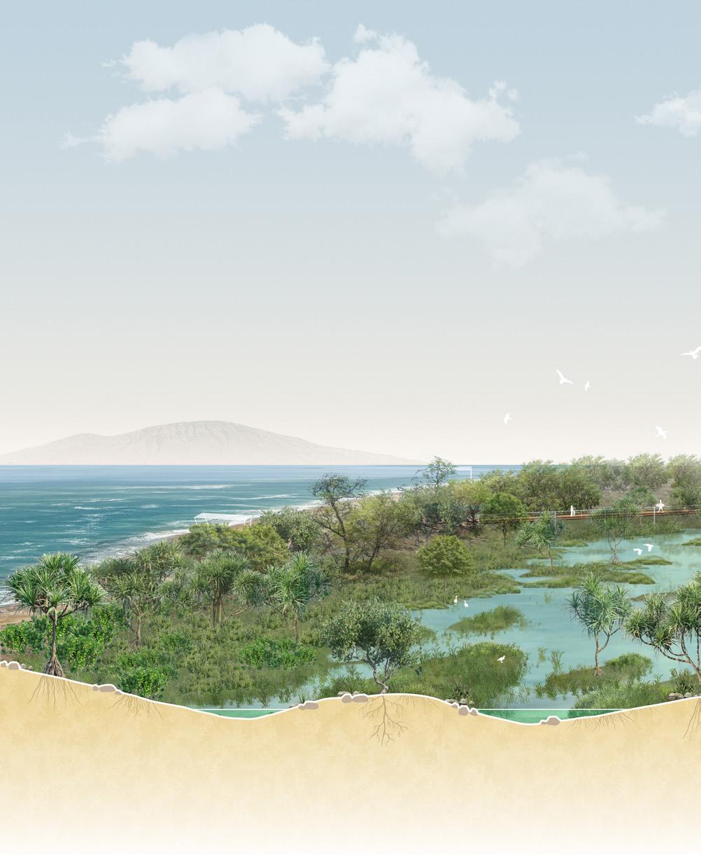
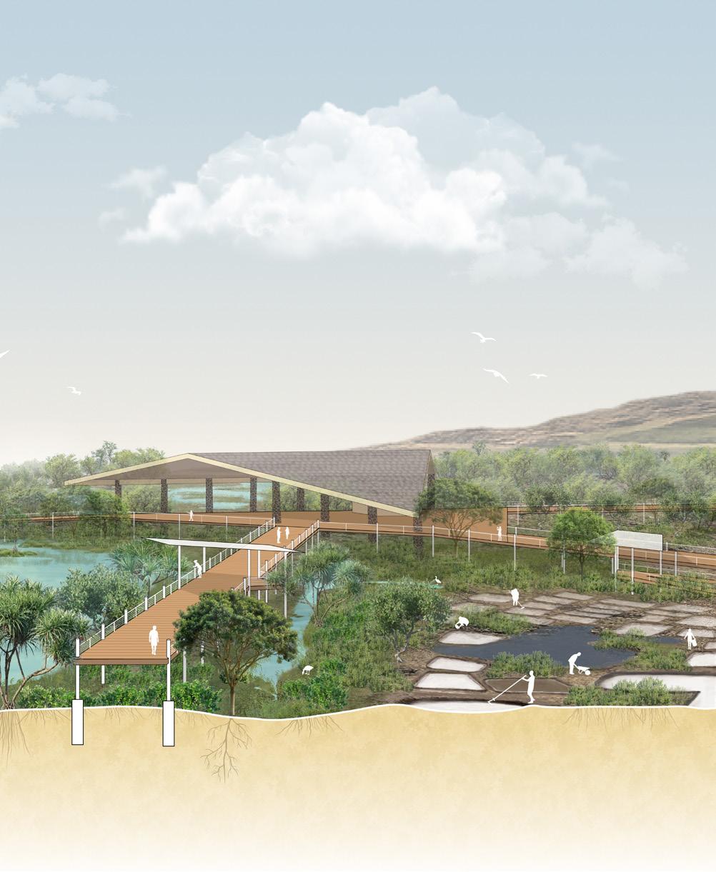
This report summarizes academic, community-engaged proof-of-concept design research and serves as a visionary educational tool intended to foster dialogue about future opportunities for resilience along the Olowalu–Ukumehame coastal corridor. The document explores speculative long-term design scenarios and does not serve as a traditional planning document.
Suggested Citation:
Stilgenbauer, J., et al., July 2026, “Olowalu: The Road to Resilience”. Prepared by the University of Hawai‘i Community Design Center (UHCDC) for The Nature Conservancy, Hawai‘i and Palmyra (TNC).
TABLE OF CONTENTS
Chapter 5 explains the proof-of-concept design approach for this project. Building on the information summarized in Chapters 2, 3, and 4 above, this chapter outlines project goals, existing site conditions, and key datasets, including SLR-XA datums and projected scenarios. It clarifies how ridge-to-reef relationships, ecological processes, access, and cultural priorities have shaped the proposed vision for the OlowaluUkumehame coastal area.
In the context of this project, proof of concept describes a scope of work that includes stakeholder involvement, applied research, conceptual planning, and design investigation. It informs subsequent fundraising or budget requests, as well as procurement of planning and design professionals. These services are preliminary and typically include, but are not limited to, a set of analyses, applied research, design schemes, criteria, and initial costs that assist with future project justification and project definition. Proof-of-concept services are typically ahead of and not in lieu of design services provided by professional consultants. However, proof-of-concept design services can be continued concurrent to professional consultants to oversee the continuity of the proof-of-concept intents.
Chapters 6 through 9 below document the actual near- and long-term proof-of-concept (P.O.C.) design visions for the overall Olowalu: The Road to Resilience project area and three exemplary catalytic sites.
Catalytic
Project Goals and Design Strategies
As indicted in the report introduction above, the Olowalu: The Road to Resilience project intends to increase the ecological, social, cultural, recreational, and economic benefits that the Olowalu-Ukumehame area’s coastal landscapes and ecosystems provide by strengthening existing relationships and reducing pressures on the reef system. The proof-of-concept design work aims to improve coastal and community resilience to help mitigate and adapt to the growing impacts of climate change, including sea level rise.
Within this framework, Chapter 5 summarizes the project’s specific proof-of-concept design goals and objectives. It demonstrates how design priorities are translated into spatial strategies that respond to environmental systems, community values, and projected change over time.
The overall project area vision (Chapter 6 below) is organized through a ridge-to-reef lens, aligning ecological processes, access networks, and cultural landscapes into an integrated system. It defines relationships between key design components and establishes where interventions are applied.
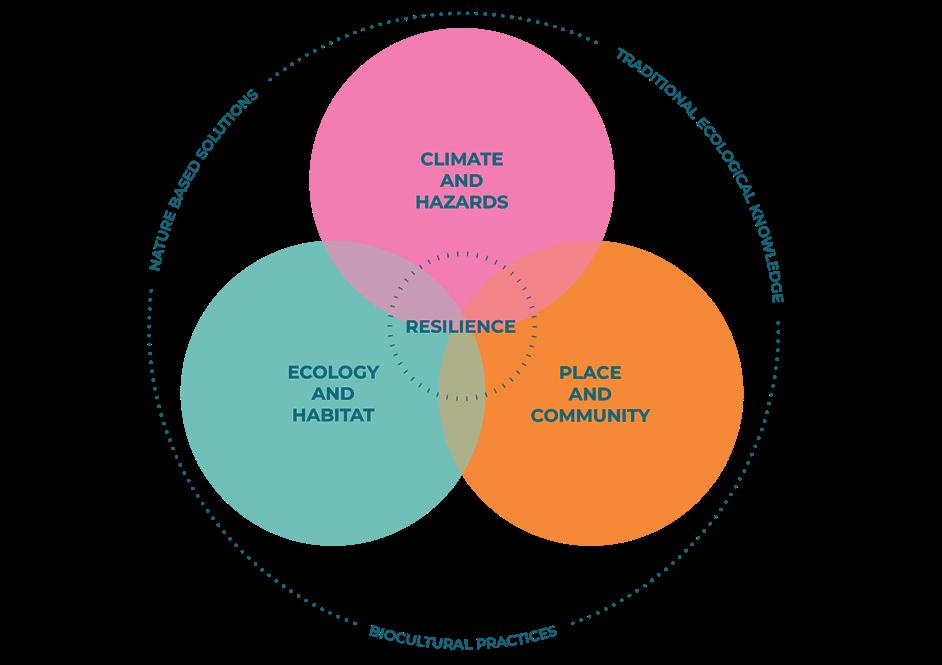
Project goals were established to guide design decisions across the Olowalu–Ukumehame coastal corridor. They are informed by the community engagement and co-design process Chapter 4 (above) and a synthesis of site analysis, including environmental systems, land use patterns, and hazard exposure. Three interrelated goal categories—place and community, ecology and habitat, and climate and hazards— form a framework that has guided discussions and helped identify shared priorities for the project area.
These design priorities respond to both community input and site conditions. They define key areas of focus, guide the proof-of-concept
design process, and inform both near-term and long-term interventions within the overall project area.
Olowalu: The Road to Resilience incorporates the project goals (pictured above) in an integrated and balanced way, rather than focusing on flood control alone. The proposed coastal resilience design responds to its location’s socio-ecological idiosyncrasies, anticipates future variable environmental conditions, and relies heavily on adaptive nature-based solutions (NBS) that are inspired by, and incorporate, Hawaiian biocultural land-water practices and modern-day interpretations of traditional ecological knowledge (TEK).
Project Goals Overview
Correlating Goals With Co-Design Feedback
The three bullet points below summarize how goals align with community feedback and priorities from the project’s engagement an co-design phases:
1 Place and Community
Near-Term: Improve access to beaches, trails, and coastal areas, including ADA and emergency routes. Provide essential amenities such as restrooms, showers, shade, and wind protection. Improve parking management and address concerns related to safety and encampments.
Long-Term: Protect and enhance access to beaches, campsites, and trail networks. Expand facilities and amenities, including showers, shade, and drop-off areas. Support community-based land use and promote education on respectful site use.
2 Ecology and Habitat
Near-Term: Restore streams, wetlands, loʻi, and fishpond systems using biocultural practices. Protect native ecosystems and support traditional fishing practices. Use restoration efforts to support education and community stewardship.
Long-Term: Restore and protect native habitats while managing invasive species. Support biocultural practices and strengthen long-term stewardship. Clarify land ownership, management, and maintenance responsibilities.
3 Climate and Hazards
Near-Term: Address immediate risks related to cesspools, flooding, fire, and pollution. Improve planning for sea level rise through modeling and near-term adaptation. Clarify roles, responsibilities, and timelines for hazard mitigation efforts.
Long-Term: Address long-term environmental pressures, including overfishing, pollution, and wind impacts. Plan for sea level rise through phased adaptation and infrastructure relocation. Establish responsibility for land care, roadway maintenance, and hazard mitigation.
Climate and Hazards Project Goal Icon
Ecology and Habitat Project Goal Icon
Place and Community Project Goal Icon
PROJECT GOALS & DESIGN STRATEGIES
The Parklands and Recreational Facilities mapping from the Honoapiʻilani Highway Improvements Final Environmental Impact Statement was used to understand how the public currently accesses and uses the Olowalu–Ukumehame coastline (FHWA and HDOT 2025). This dataset identifies a series of beach and shoreline access points distributed along the corridor, including both formally designated parks and informal access locations. Together, these provide a baseline understanding of where and how the coastline is currently experienced.
Review of this mapping revealed that access to the shoreline is not continuous, but occurs at discrete locations distributed along the highway corridor. Beach parks function as primary nodes of activity, while informal pull-offs and roadside entry points provide additional access opportunities. Movement is largely oriented
along the Honoapiʻilani Highway, with engagement occurring at points where physical access is possible. This results in a dispersed pattern of use, where the coastline is experienced through a sequence of arrival points rather than as a continuous public landscape.
During the engagement and co-design phases of the Olowalu: The Road to Resilience project, members of the local community voiced their clear preference and desire for continued access to the shoreline post highway relocation. The pattern of existing coastal access described above highlights important differences between sites. While many locations support short-term recreational use, others accommodate a broader range of activities that extend beyond shoreline access. These include gathering, longer-duration use, and interactions that are not strictly tied to the shoreline itself. The
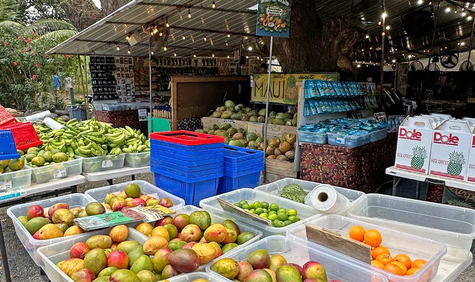
Olowalu farmers market (UHCDC, 2025)
Place and Community
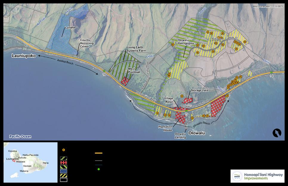
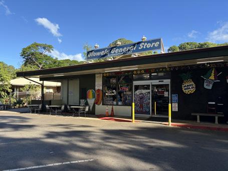
Final Environmental Impact Statement identifies a cluster of small businesses in Olowalu, including Olowalu General Store, Leoda’s Kitchen and Pie Shop, and the Olowalu Farmers Market, which serve both residents and visitors traveling through the corridor (FHWA and HDOT 2025). These uses contribute to a concentration of activity that is not present at other access points.
In addition to contemporary use, Olowalu reflects a layered historical landscape. The Olowalu Landing area, identified in the Final Environmental Impact Statement as the primary parking area for Olowalu Beach, contains remnant structures associated with the former sugar plantation. These features reflect past agricultural and industrial uses that have shaped the present-day condition of the site. The area currently functions as an informal access point. It continues to support active use, including shoreline access, gathering, and small-scale cultivation.
lu functions as more than a point of entry to the coastline. Instead, it operates as a place-based node within the corridor, where shoreline access, economic activity, and historical landscape intersect. This distinguishes it from other shoreline access points, which are more limited in function and duration of use.
While patterns of access and recreation occur throughout the corridor, this analysis highlights that not all sites contribute equally to the goal of place and community. Sites that support multiple forms of use, particularly those that combine access with social and economic activity, play a more significant role in shaping the identity cultural and place-making of the project area.
Through this lens, Olowalu Town emerged as the site most strongly aligned with the goal of place and community, informing its selection as a catalytic site within the overall project area
Honoapiʻilani Highway Improvements Project, West Maui, Ukumehame to Launiupoko Final Environmental Impact Statement
FIGURE 3.1-2. Project Area Land Uses: Olowalu
PROJECT GOALS & DESIGN STRATEGIES
in Ukumehame Firing Range on January 3, 2023
Ecology and Habitat
The Olowalu-Ukumehame coastal corridor contains ecological systems shaped by both natural processes and long-term human disturbance. The Final Environmental Impact Statement (FEIS) identifies the area as a coastal dryland ecosystem typical of leeward Hawaiʻi, where vegetation is largely dominated by nonnative and invasive species due to a history of agricultural use, wildfire, and infrastructure development (FHWA and HDOT 2025). These conditions reflect a landscape that has been significantly altered, resulting in fragmented habitat systems and reduced ecological performance, biodiversity, and continuity.
ogy, sediment transport, and nearshore conditions. Low-lying coastal areas and remnant wetlands support transitional environments where freshwater and marine systems interact, creating conditions that can support habitat even within a modified landscape.
H. T. Harvey & Associates November 2023
Despite these changes, important ecological functions persist across the project area. Stream systems, including Olowalu and Ukumehame, provide critical connections between mauka and makai environments, influencing hydrol-
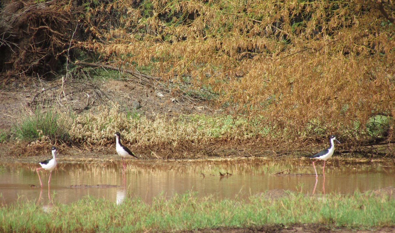
Review of ecological data and field observations revealed that these functions are not evenly distributed. Certain areas exhibit greater ecological significance due to the presence of water, lower elevation, and connectivity to coastal processes. The FEIS documents the presence of native and endangered waterbird species, including aeʻo (Hawaiian stilt) and nēnē (Hawaiian goose), within the Ukumehame area (FHWA and HDOT 2025). These observations indicate that, despite overall landscape disturbance, this location continues to function as habitat within a broader ecological network.
Hawaiian Stilt or Aeʻo, Himantopus mexicanus knudseni, at Ukumehame Firing Range on January 4, 2023 (FHWA & HDOT, Honoapiʻilani Highway Improvements Project FEIS, 2025)
Photo 31. (Branta sandvicensis) Resting Under the Shade of the Classroom Building
Photo 32. Hawaiian Stilt or ae ʿ o ( Himantopus mexicanus knudseni) at Ukumehame Firing Range on January 4, 2023
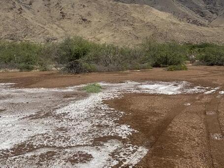
The Ukumehame area is also characterized by low-lying topography and hydrologic conditions that make it particularly responsive to coastal processes. Sea level rise exposure mapping indicates that projected future inundation will extend further inland in this area compared to other portions of the coastal corridor, influenced by both surface flooding and groundwater dynamics. This creates conditions where ecological processes, including wetland formation and habitat expansion, may become more pronounced over time.
In addition to ecological value, the presence of the adjacent Ukumehame Firing Range introduces an additional layer of complexity. The site has been the subject of ongoing discussion regarding its long-term use, reflecting competing perspectives related to safety, access, and land management. These overlapping conditions position Ukumehame as a location where ecological systems, environmental change, and human use intersect in dynamic ways.
This analysis demonstrates that ecological conditions within the project area are not uniform, but concentrated in locations where hydrology, elevation, and habitat potential align. Sites that support these processes offer opportunities not only for preservation, but for restoration and enhancement within the context of changing environmental conditions.
Through this lens, the Ukumehame beach park and wetland area emerged as the site most strongly aligned with the goal of ecology and habitat, where hydrologic processes, habitat function, and future environmental change converge.
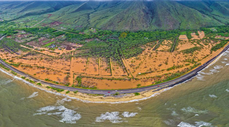
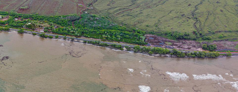
Ukumehame after Kona-low storms (Mark Deakos & TNC, March 2026)
PROJECT GOALS & DESIGN STRATEGIES
Climate and Hazards
The Olowalu–Ukumehame coastal corridor is subject to a range of coastal hazards that influence the long-term function of land, infrastructure, and public access. The Final Environmental Impact Statement identifies flooding, wave overtopping, shoreline erosion, and drainage limitations as key processes affecting the corridor (FHWA and HDOT 2025). These hazards are closely tied to the physical relationship between the coastline and the existing Honoapiʻilani Highway alignment.
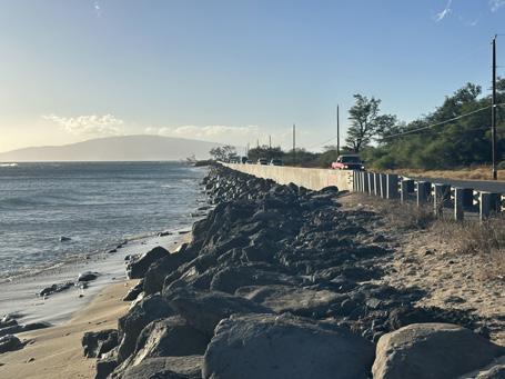
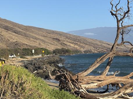
In many locations, the highway is situated immediately adjacent to the shoreline, limiting the ability of coastal systems to migrate inland and increasing exposure to wave action and erosion. Low-lying areas are particularly vulnerable to flooding, where high water levels, storm events, and constrained drainage contribute to recurring inundation. These conditions affect
not only infrastructure performance, but also the safety and accessibility of shoreline access points. Analysis of hazard conditions across the corridor revealed that exposure is not uniform, but varies based on elevation, shoreline configuration, and proximity to coastal processes. Certain locations exhibit a more direct interaction between infrastructure and the ocean, where the effects of flooding, erosion, and wave action are already evident.
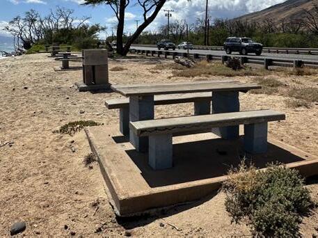
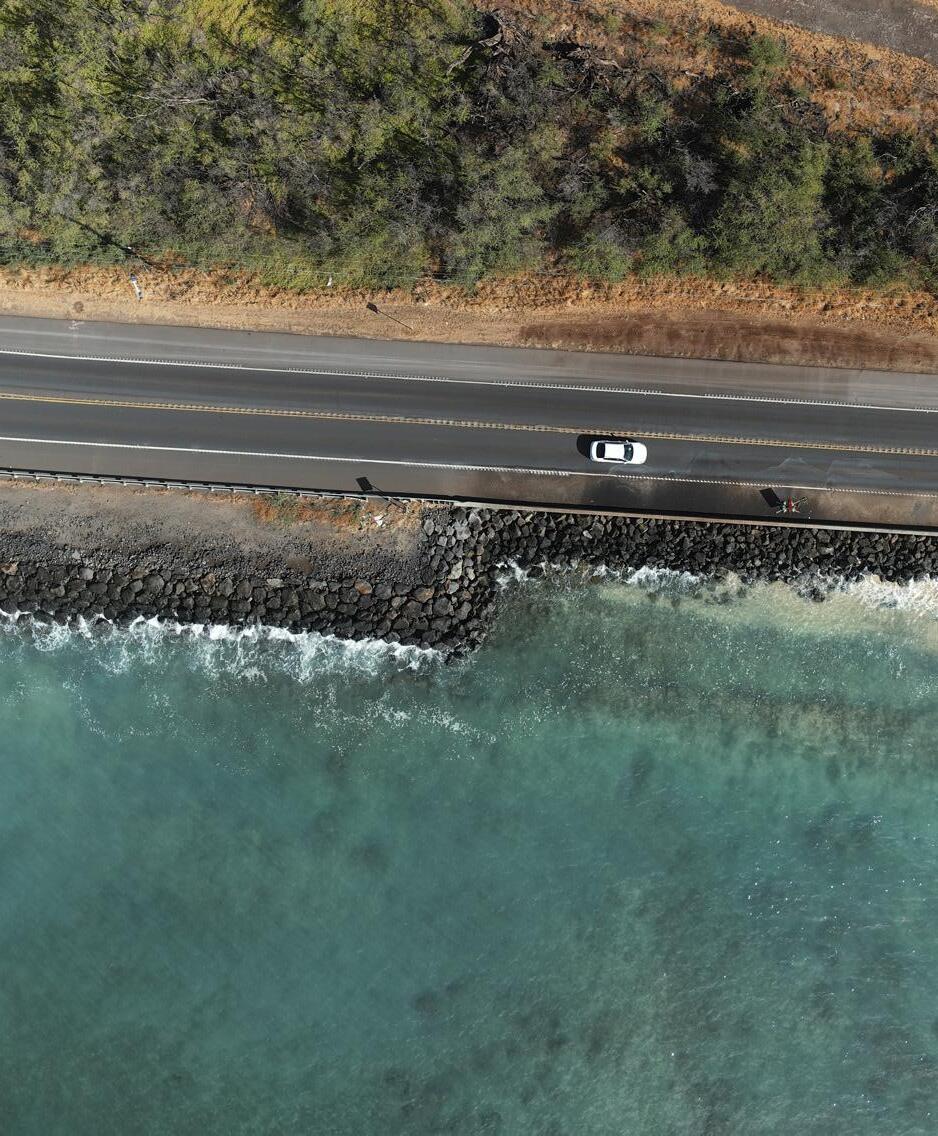
Mile Marker 14 illustrates this condition. Although not formally designated as a beach park, it is a well-used snorkeling location accessed through informal roadside pull-offs, which contribute to erosion and sediment issues. The absence of defined parking and circulation creates safety concerns for both vehicles and pedestrians, particularly along a highway corridor where stopping conditions are limit-
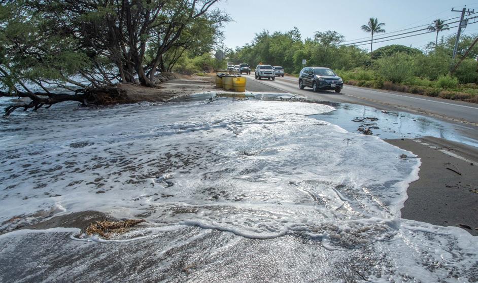
Ocean water from king tide flooding inundates Honoapiʻilani Highway near Mile Marker 14 in Olowalu (Maui Now, Asa Ellison, 2019)
ed. At the same time, the site remains a valued recreational location, indicating a disconnect between its level of use and the infrastructure provided to support it.
The site is further shaped by the convergence of intermittent stream systems, including Kailiʻili, which influence sediment movement, drainage, and nearshore conditions. These processes contribute to a dynamic coastal environment where flooding and erosion are ongoing, and where future conditions are likely to become more unstable with sea level rise.
Cultural resources also influence the limits of intervention at this location. The presence of a nearby heiau establishes the area as culturally sensitive, requiring careful consideration of land use and development. As identified in the Final Environmental Impact Statement, Native Hawaiian cultural sites must be protected and integrated into planning decisions, constraining the type and extent of potential interventions (FHWA and HDOT 2025). This combination of high public use, environmental exposure, and cultural constraint highlights the complexity of hazard conditions within the corridor. Sites such as Mile Marker 14 demonstrate that areas of greatest risk are often also areas of continued use, requiring approaches that balance safety, access, and environmental change.
catalytic site where infrastructure vulnerability, coastal processes, and cultural constraints intersect. In this location, the overarching project goals of climate and hazard, as well as place and community, merge in mutually important ways.
Coastal Resilience
Climate-resilient socio-ecological waterfront systems result where the project goals identified above overlap and design objectives intersect. By investigating past, present, and planned shoreline conditions, the Olowalu: The Road to Resilience project advocates for the anticipation of climate-crisis challenges through forward-looking visioning, planning, and design, embracing dynamic conditions, such as coastal flooding, rather than preventing them.
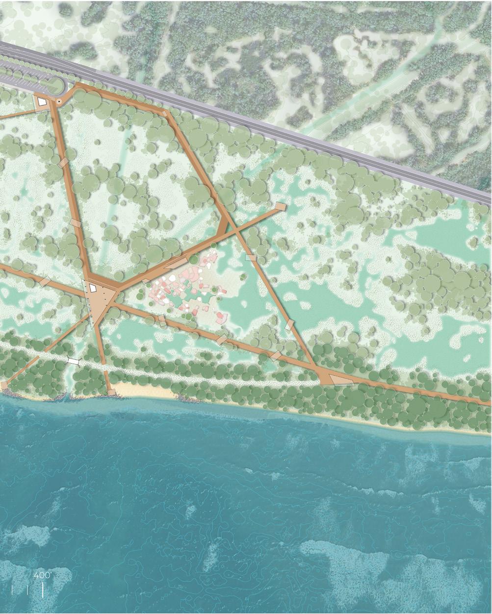
The large-scale, long-term visioning concepts depicted in Chapter 6 below propose connected, varied, and dynamic networks of open spaces and waterfront conditions that decrease coastal vulnerabilities by responding to shoreline changes and issues related to aging infrastructure. The project features multi-purpose coastal green infrastructure systems, linked public open spaces, multi-purpose paths and elevated boardwalks, and networks of ecological priority zones as essential drivers of the Olowalu-Ukumehame coastal corridors future
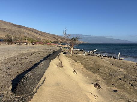
Mile Marker 14 after Kona-low storms (Mark Deakos & TNC, March 2026)
PROJECT GOALS & DESIGN STRATEGIES
Design Strategies Overview
The concepts summarized in this section establish the foundational strategies that inform the proof-of-concept design for the Olowalu-Ukumehame coastal corridor. Building on community priorities and site conditions, these concepts frame how the design responds to sea level rise, ecological restoration, access, and long-term resilience.
1 Open Space Network
The concept of establishing a continuous network of various types of coastal open spaces aims to reconnect communities to the shoreline while supporting ecological and cultural functions. Building on the opportunity created by the Honoapiʻilani Highway realignment, this approach reimagines the project area as a linked system of parks, restored landscapes, nature-based adaptation solutions, and gathering spaces.
Strategies include:
• Create a continuous yet varied coastal open space network
• Establish distributed park nodes for recreation, gathering, and cultural use
• Integrate restoration areas within public open space systems
• Provide flexible spaces that can adapt to changing environmental conditions
This concept organizes the project area as a connected public landscape, linking Olowalu, Ukumehame, and surrounding areas through accessible, multifunctional open space.
2 Multimodal Access and Connectivity
A multi-use approach to access supports safe, equitable movement across the corridor while improving connections between mauka and makai. By expanding transportation options beyond vehicular travel, this strategy enhanc-
Kauai Bike Path: multimodal access and connectivity with project color overlay (adapted by UHCDC from Kauai Path, 2024)
es daily use, recreation, and emergency access while reducing pressure on a single roadway system.
Strategies include:
• Develop multi-use paths for pedestrians and cyclists
• Improve mauka-to-makai connections across the project area
• Provide safe and accessible routes, including ADA and emergency access
• Integrate with proposed regional systems such as the West Maui Greenway
This concept establishes a continuous network of movement that connects coastal parks, cultural sites, and ecological areas, supporting both everyday access and long-term resilience.
3 Community Feedback and Iteration
The proof-of-concept design is developed through an iterative process that integrates community knowledge, cultural values, environmental analysis, and resilience planning. Residents, lineal descendants, cultural practitioners, and other stakeholders participate throughout the engagement process to identify key priorities for the Olowalu–Ukumehame coastline, helping to shape and refine design strategies and program elements.
By repeatedly responding to community input, the proof-of-concept design reflects a collective vision rather than one developed by a single entity. Representative iterations of proof-of-concept design drawings are included below.
4 Nature-Based Solutions and Biocultural Practices
Nature-based solutions and biocultural practices integrate ecological restoration with traditional knowledge systems, supporting both environmental function and cultural continuity. These approaches strengthen relationships between land, water, and community while enhancing long-term resilience.
Strategies include:
• Restore wetlands, loʻi, and nearshore habitats
• Establish native vegetation for erosion control and habitat enhancement
• Reduce sediment transport through watershed restoration
• Integrate traditional stewardship and land management practices
This concept supports ridge-to-reef connectivity and reinforces ecological function while maintaining cultural relationships to place.
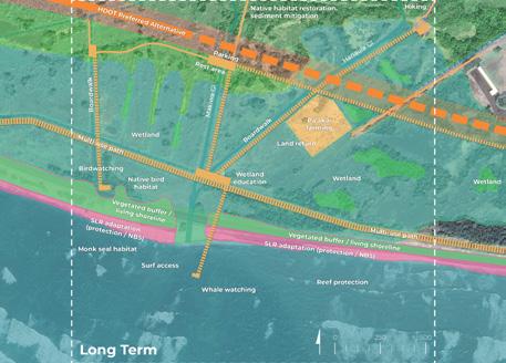
Co-Design Phase 1, Catalytic Site 3 Long-Term POC Design (UHCDC, June 2025)
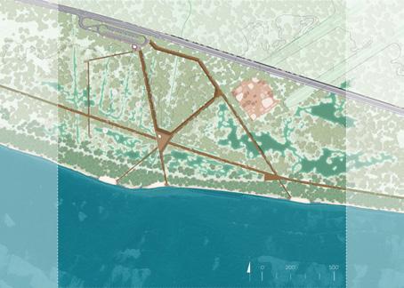
Co-Design Phase 2, Catalytic Site 3 Long-Term POC Design (UHCDC, November 2025)
PROJECT GOALS & DESIGN STRATEGIES
5 Sea Level Rise Adaptation Strategies
The design approach for the Olowalu-Ukumehame coastal corridor applies a range of sea level rise adaptation strategies to respond to varying levels of exposure across the site. Based on 1.1-foot and 3.2-foot SLR-XA scenarios, these strategies address both near-term and longterm conditions, guiding how different areas of the corridor can function over time.
Rather than relying on a single solution, the approach combines multiple strategies to respond to site-specific conditions, including flooding, erosion, and groundwater inundation. In Hawaiʻi, adaptation strategies are generally understood as a combination of protection, accommodation, and retreat, each applied based on the timing and severity of coastal hazards (Hawaiʻi Climate Change Mitigation and Adaptation Commission 2022).
Nature-Based and Living Systems
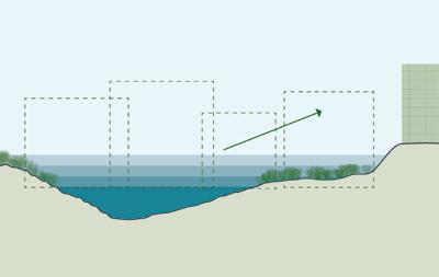
Soft blue-green infrastructure that supports ecosystem services, increases the distance between water and the built environment, retains and absorbs inundation, attenuates waves, slows erosion, provides habitat, and contributes to biodiversity. Examples: wetlands, tidal marshes, and other living coastal buffers.
Managed Retreat (Relocation)
Long-term relocation or removal of existing buildings, infrastructure, and resources out of hazard areas to higher elevations and limited construction of new development in vulnerable areas. Planned withdrawal from the shoreline and/or low-lying zones over time through strategic relocation. Example: Honoapiʻilani Highway re-alignment.
The key adaptation strategies listed below support a phased and flexible response that can evolve as conditions change. While these strategies have informed the overall project design, they are most clearly visualized at the catalytic site scale, where design interventions are represented in greater detail.
At these locations, strategies are applied to specific site conditions, illustrating how different approaches can be combined to support coastal resilience, maintain access, and accommodate changing environmental processes over time.
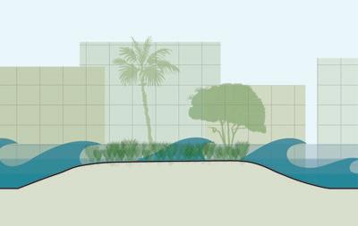
Hardened Shoreline Protection
Hard, engineered, linear infrastructure systems designed to defend, armor, and stabilize the shoreline and resources in their current location. Examples: impermeable structures, seawalls, levees, dikes, revetments, groins, breakwaters, riprap, dams, flood gates, storm surge barriers, etc.
Floodable Structures and Landscapes
Structures and landscapes designed to withstand and function during inundation events. Accommodating habitable space, critical assets, and vulnerable infrastructure on upper levels or at higher elevations decreases hazard risks and increases resilience to the impacts of sea level rise and flooding.
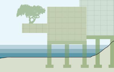
Elevated Structures and Landscapes
Accommodating in place by raising the height of land, infrastructure, buildings, and other resources for existing or new development over time to safer elevations using fill and/or pilings with the goal of decreasing hazard risks and increasing resilience to the impacts of sea level rise and flooding.
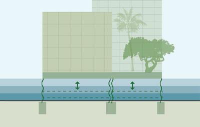
Floating Structures and Landscapes
Accommodating and adapting in place by floating buildings, transportation elements, and infrastructure designed with fluctuating and rising water levels in mind has the potential to increase resilience to the impacts of sea level rise and flooding. Structures are fastened to the coast or bottom of water with flexible connections.
3.2’ SLR-XA projection in the Olowalu-Ukumehame coastal corridor (sea level rise data sourced from Pacific Islands Ocean Observing System (PacIOOS), September 2024, map adapted by UHCDC)
Project Timeline and SLR-XA Datums
The proof-of-concept visions and design drawings included in Chapters 5 thought 9 below are organized in sequential order, ranging from existing conditions to proposed near-term conditions, followed by proposed long-term conditions.
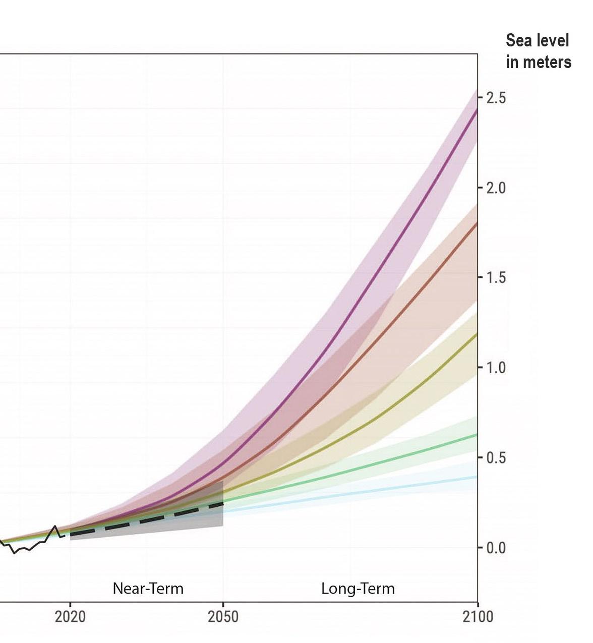
This subchapter introduces the project’s overarching time scale, which is guided by the anticipated Honoapiʻilani Highway relocation schedule and sea level rise projections from NOAA’s 2022 Intermediate High sea level rise scenario for Hawaiʻi.
1.1 feet of sea level rise, anticipated around 2045—and, more specifically, the 1.1-foot sea level rise exposure area (SLR-XA)—serve as the near-term proof-of-concept design benchmark throughout this project.
3.2 feet of sea level rise, anticipated around 2075 based on current projections—and, more specifically, the 3.2-foot sea level rise exposure area (SLR-XA)—serve as the long-term proof-of-concept design benchmark for Olowalu: The Road to Resilience.
Design Timescale
Sea level rise projections are used to establish a planning timescale for this project, defining near-term and long-term conditions that inform design decisions. These projections are based on regional guidance from the Hawaiʻi Sea Level Rise Vulnerability and Adaptation Report and sea level rise scenarios developed by the National Oceanic and Atmospheric Administration (NOAA).
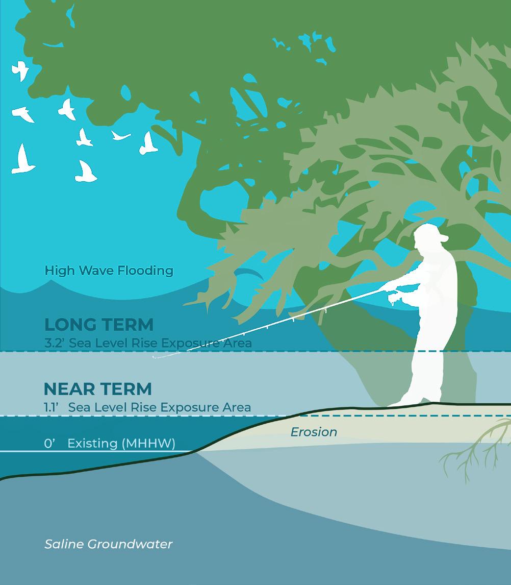
The Sea Level Rise Exposure Area (SLR-XA) represents the combined area of risk from passive sea level rise flooding, annual high-wave flooding, and coastal erosion. By integrating these processes into a single dataset, SLR-XA provides a comprehensive representation of coastal hazard exposure and informs planning and infrastructure decisions (Hawaiʻi Climate Change Mitigation and Adaptation Commission 2022).
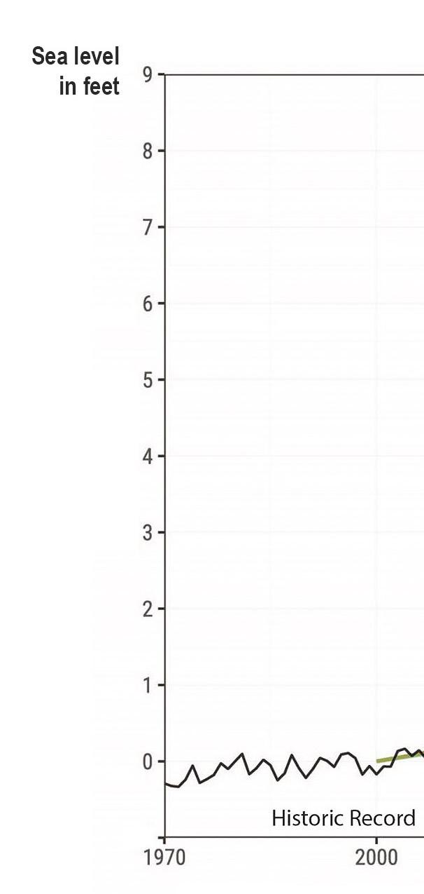
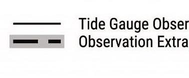
Sea level rise projections for Hawaiʻi indicate a continued increase in ocean water levels over time, with uncertainty increasing in the latter half of the century. The figure to the right illustrates a range of scenarios developed by NOAA for Hawaiʻi, showing both observed trends and projected future conditions.
For the purposes of this project, two thresholds are used to define the design timescale. Nearterm scenarios are based on approximately 1.1 feet of sea level rise, corresponding to conditions anticipated around 2045. Long-term scenarios are represented by approximately 3.2 feet of sea level rise, corresponding to conditions anticipated around 2075 and consistent with statewide planning benchmarks.
These thresholds are applied through the SLRXA to evaluate how coastal exposure expands over time. By linking projected sea level rise to defined time horizons, the project establishes a framework for phased design, allowing interventions to respond to both current conditions and anticipated future change.
al. 2022, Figure: Jaimie Carter (https://oceanservice.noaa.gov/hazards/sealevelrise/sealevelrise-tech-report.html)
PROJECT TIMELINE AND SLR-XA DATUMS
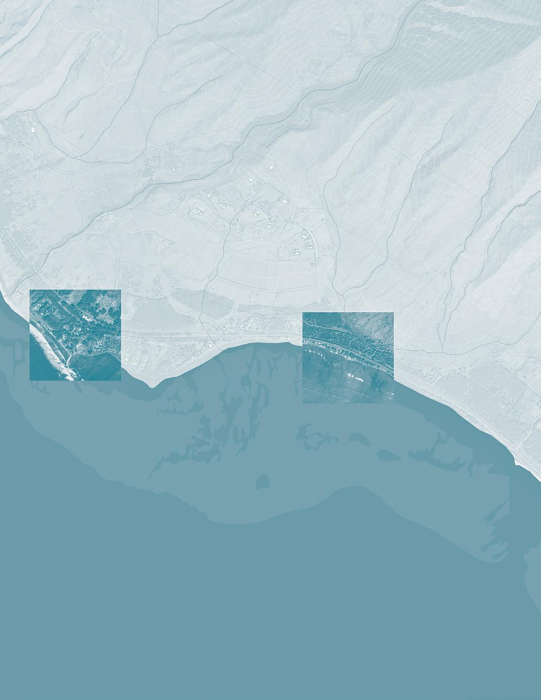
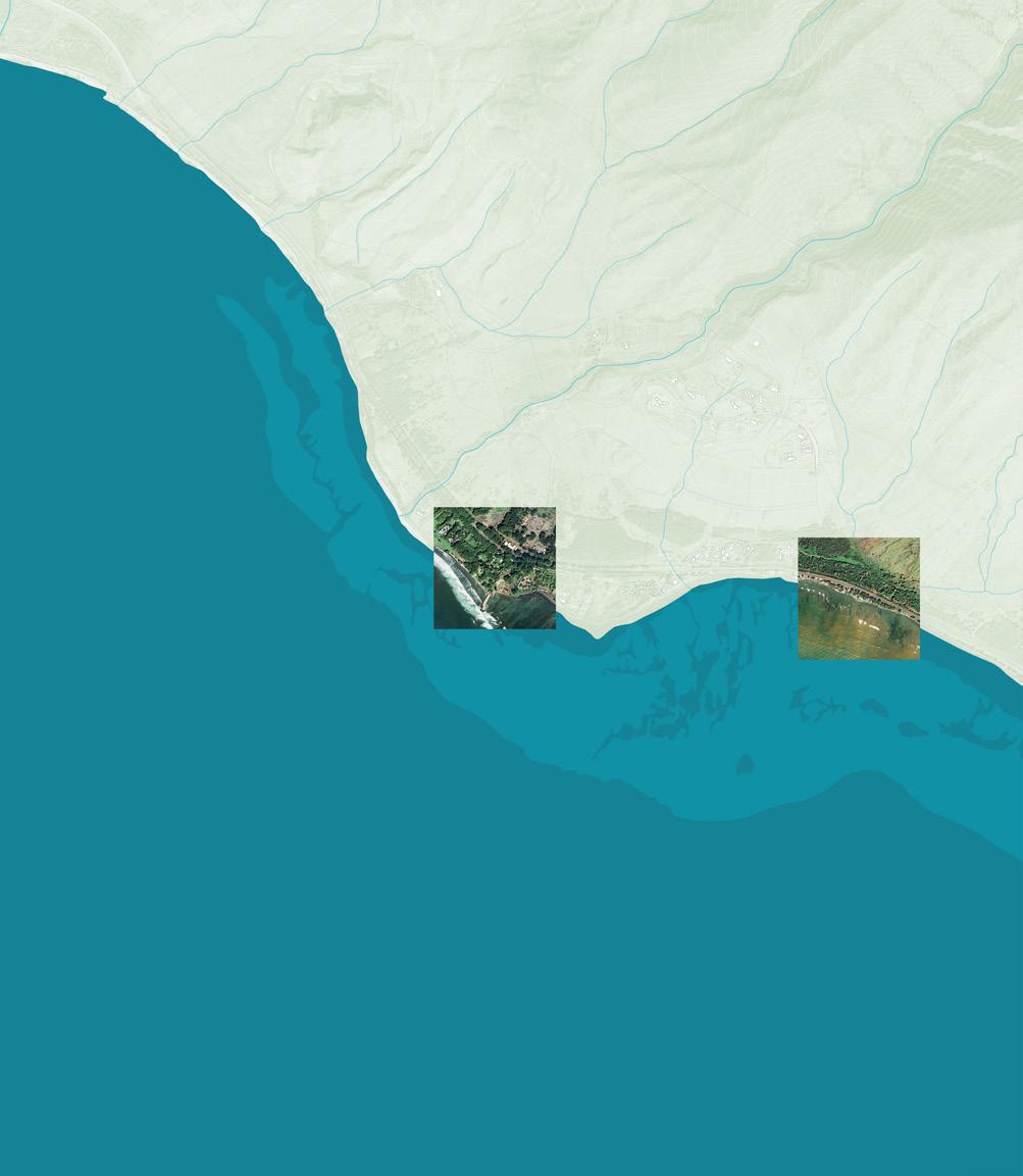
Catalytic Sites 1 & 2 highlighted with aerial images (UHCDC)
Catalytic Site Selection
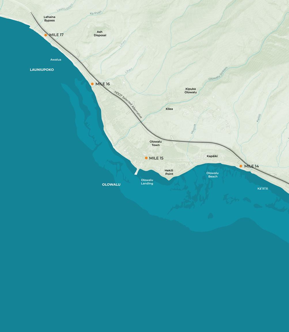
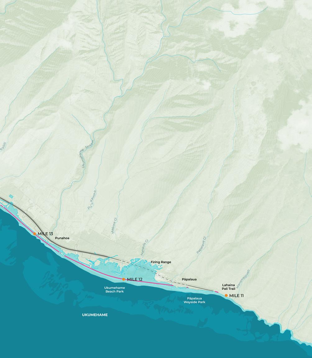
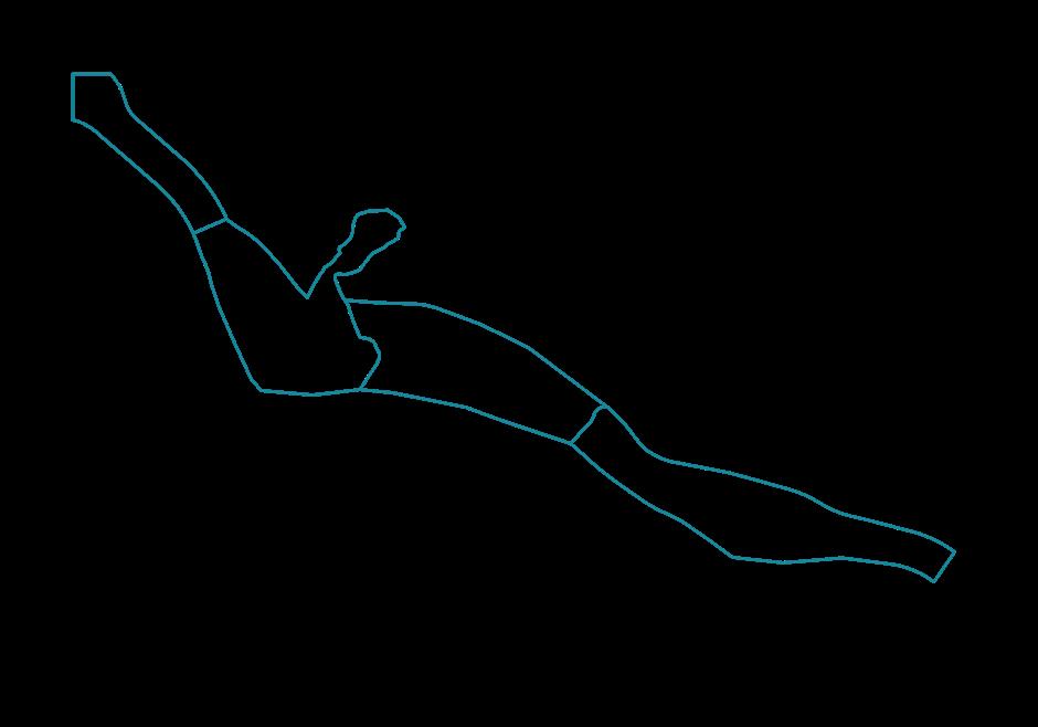
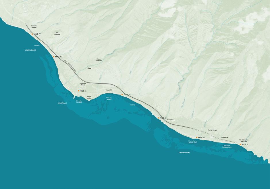
Because the approximately 6-mile-long project area for Olowalu: The Road to Resilience is quite large for a visioning project, proposed overall conceptual design interventions are broad-stroke in character, focusing on the big picture and general recommendations (see Chapter 6 below).
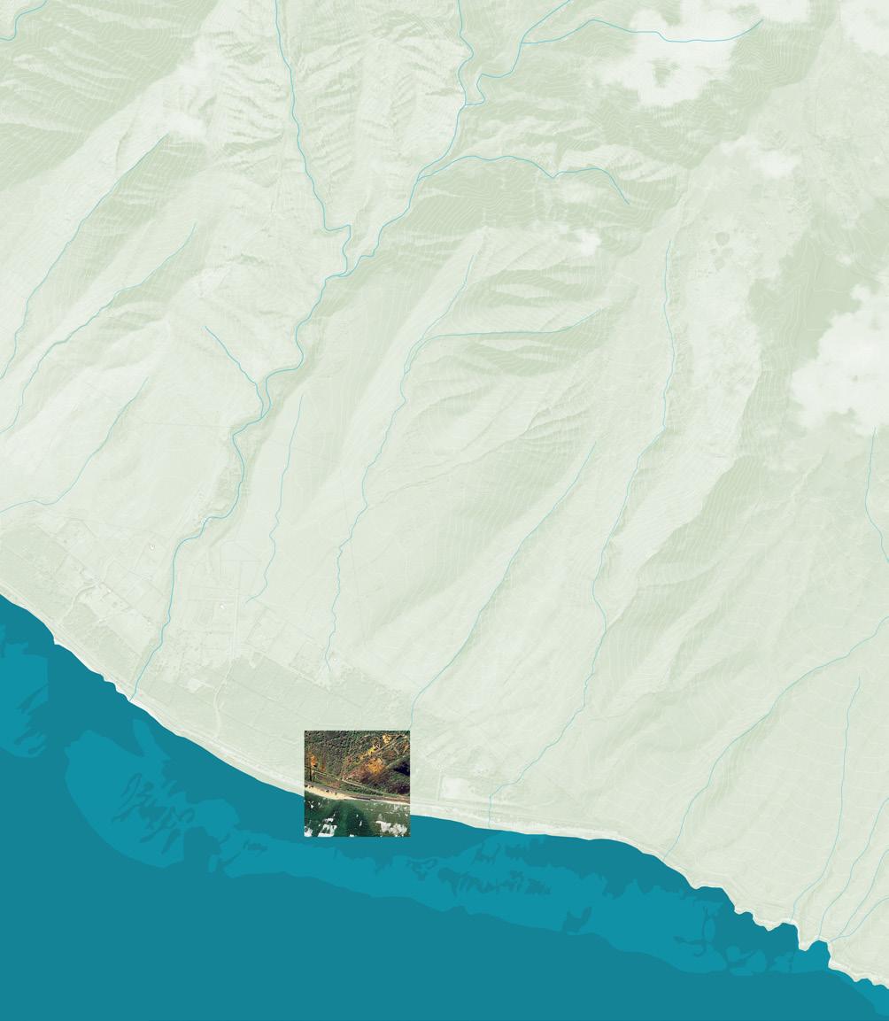
For that reason, the project team decided early on in the process to zoom in to a number of important locations within the Olowalu–Ukumehame corridor to allow for more detailed analysis and design investigation. As a result—based on site inventory and community input—three 2000-ft by 2000-ft coastal sites were selected, each illustrating specific aspects of existing conditions, climate hazards, project goals, design strategies, and potential sea level rise adaptation interventions over time.
The three catalytic sites detail important aspects of the overall proof-of-concept design framework plan. They highlight specific instances of coastal resilience or habitat/cultural restoration accommodations and recreational opportunities—typical adaptation solutions that might also be applicable to other parts of the overall project area.
Studying these locations in greater detail, allowed the project team to propose and visualize tangible conceptual design solutions intended to stimulate discourse and serve as potential models for other, similarly situated areas within the overall project extent.
The following report pages show the location of the project’s three catalytic sites within the overall project area. Report chapters 7 through 9 (below) introduce and analyze the three catalytic site locations’ existing conditions before illustrating proposed near- and long-term conceptual design interventions.
Catalytic Sites:
Catalytic Site 1: Olowalu Landing
Catalytic Site 2: Mile Marker 14
Catalytic Site 3: Ukumehame Beach Park and Wetlands
CATALYTIC SITE SELECTION
Existing Conditions
0’ 2,000’ 4,000’
SCALE: 1” = 2,000’ (if printed on 11”x17”)
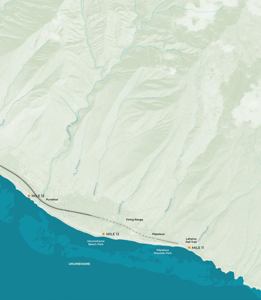
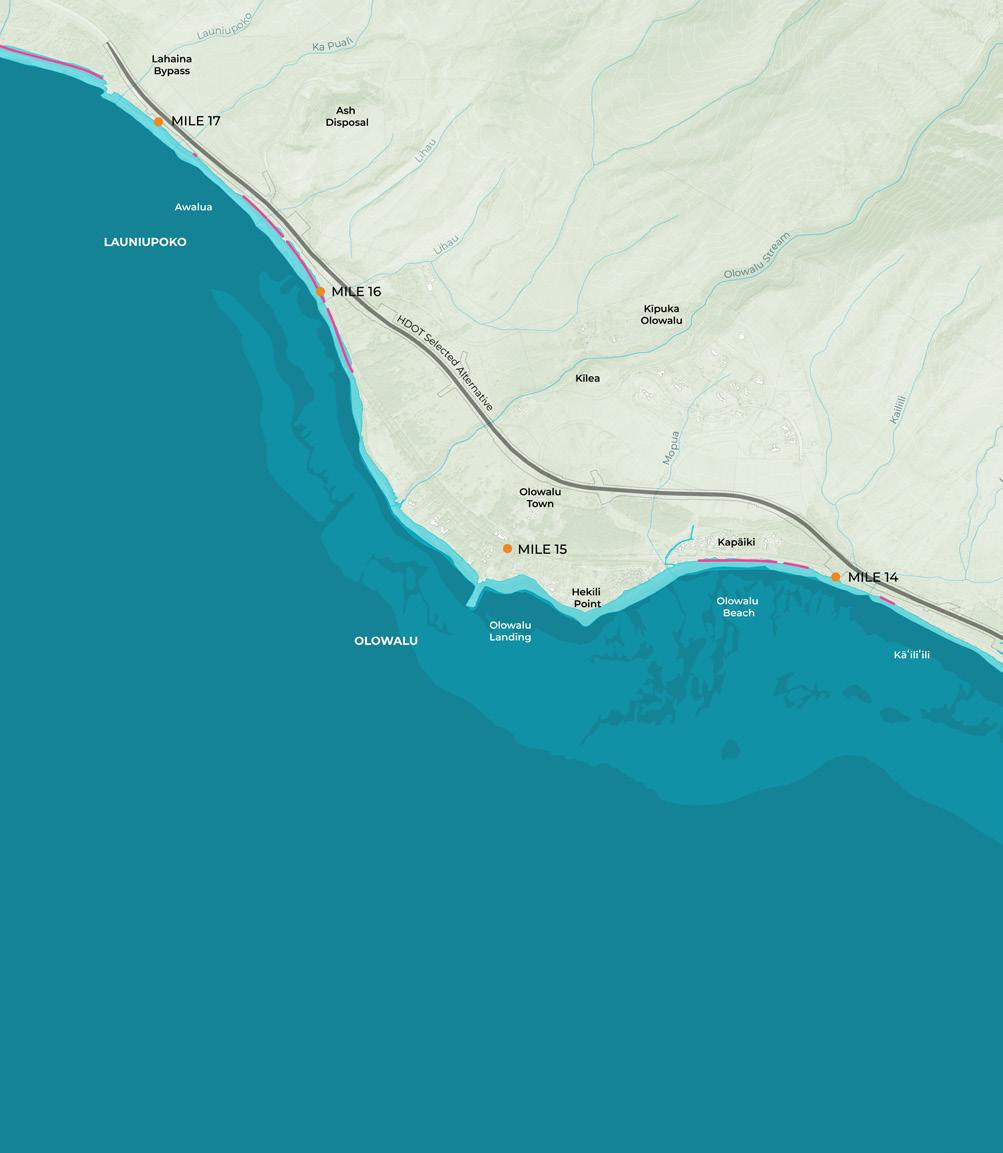
Project Area Conditions and Site Systems
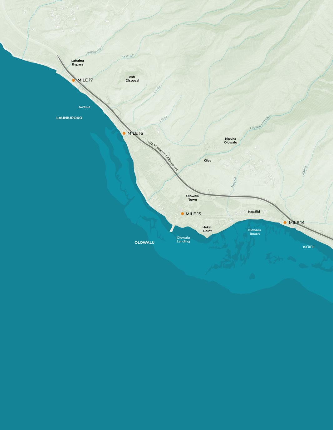
The identification of catalytic sites is informed by an overlay of existing corridor conditions, including topography, hydrology, land ownership, and transportation infrastructure. These layers provide a comprehensive understanding of how natural systems and built elements interact across the Olowalu-Ukumehame coastline.
Key features such as perennial streams, coastal lowlands, and existing roadway alignments play a significant role in shaping patterns of exposure and access. The preferred Honoapiʻilani Highway realignment further influences how the corridor may function in the future, particularly in relation to the decommissioning of the existing coastal highway.
Together, these systems establish the physical and spatial framework within which sea level rise impacts occur. Understanding these relationships is critical for identifying where targeted interventions can support both ecological function and public access at the project area scale.
1.1’ Sea Level Rise Projection - Approximately 2045
0’ 2,000’ 4,000’
SCALE: 1” = 2,000’ (if printed on 11”x17”)
Data source: National Oceanic and Atmospheric Administration sea level rise data (September, 2024)
Near-Term Scenario
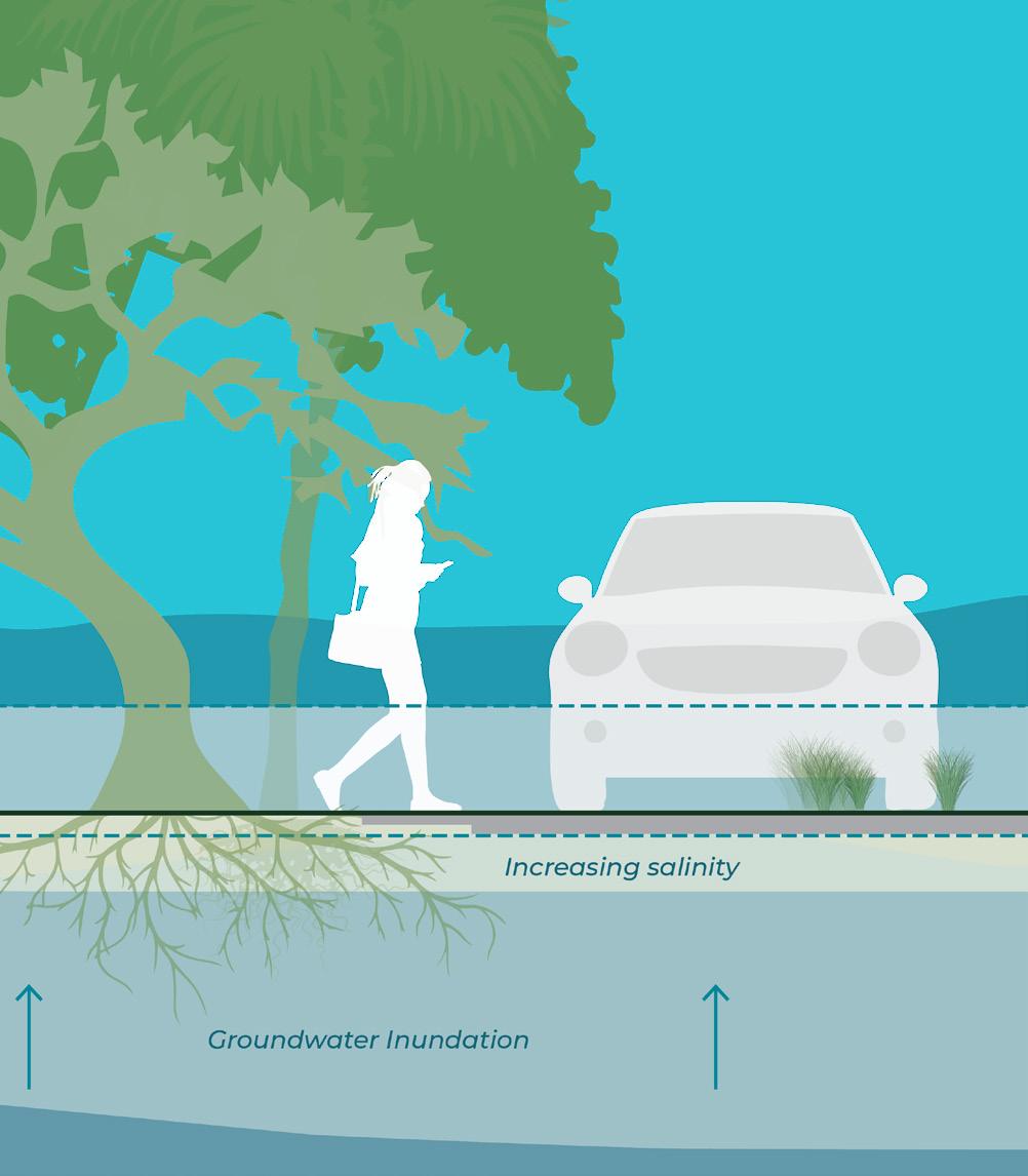
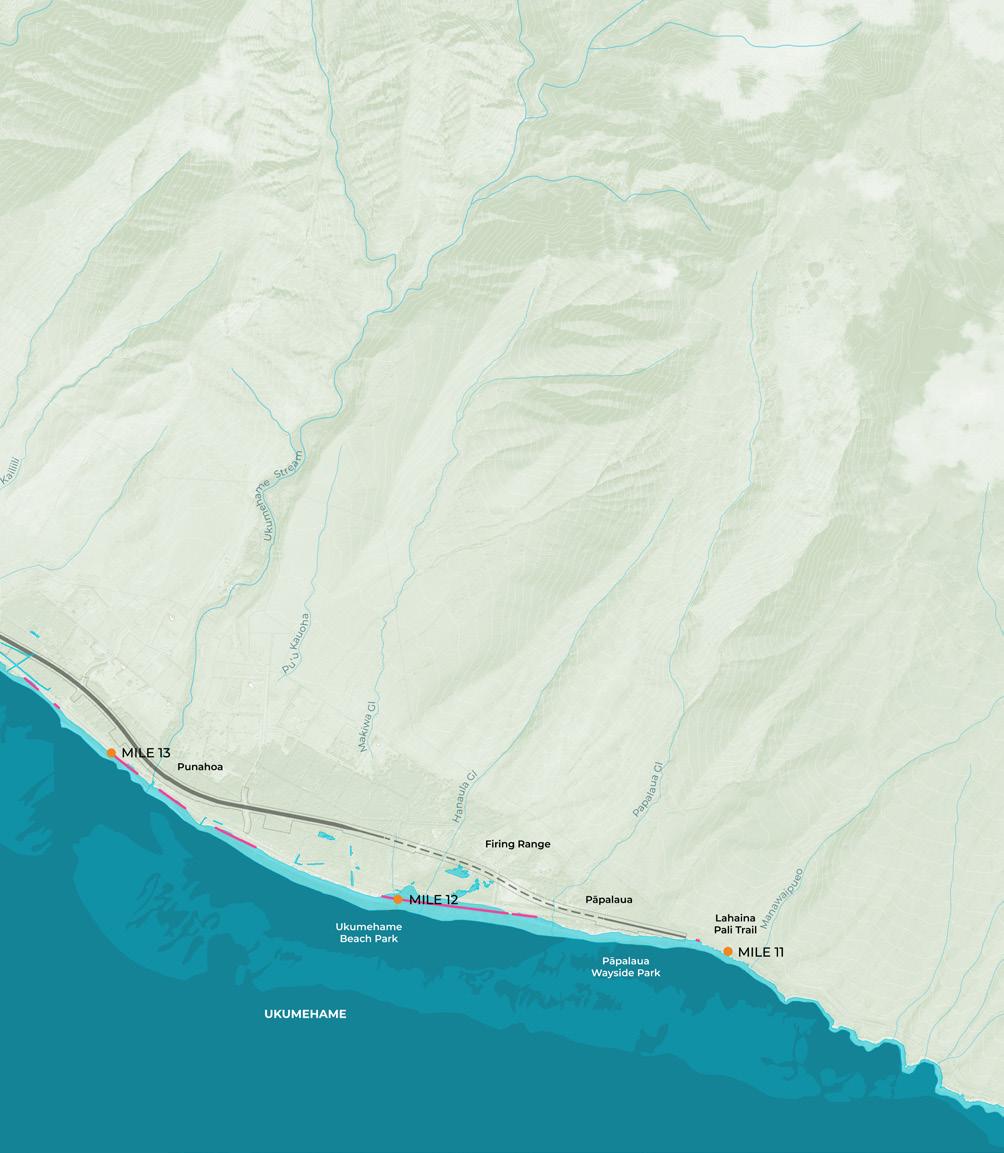
Under the 1.1-ft sea level rise scenario, exposure is concentrated in the project area’s low-lying coastal areas. These areas are subject to increased frequency of flooding, wave runup, and groundwater emergence, which affect soil conditions, drainage capacity, and accessibility.
These patterns reflect the combined influence of marine and groundwater-driven flooding processes as represented in the Sea Level Rise Exposure Area (SLR-XA), where passive flooding, high-wave events, and subsurface water table rise interact (Hawaiʻi Climate Change Mitigation and Adaptation Commission 2022).
At this stage, impacts are typically episodic but increasing in frequency, indicating areas where near-term design interventions must accommodate periodic inundation while maintaining functionality.
3.2’ Sea Level Rise Projection - Approximately 2075
0’ 2,000’ 4,000’
SCALE: 1” = 2,000’ (if printed on 11”x17”)
Data source: National Oceanic and Atmospheric Administration sea level rise data (September, 2024)
Long-Term Scenario
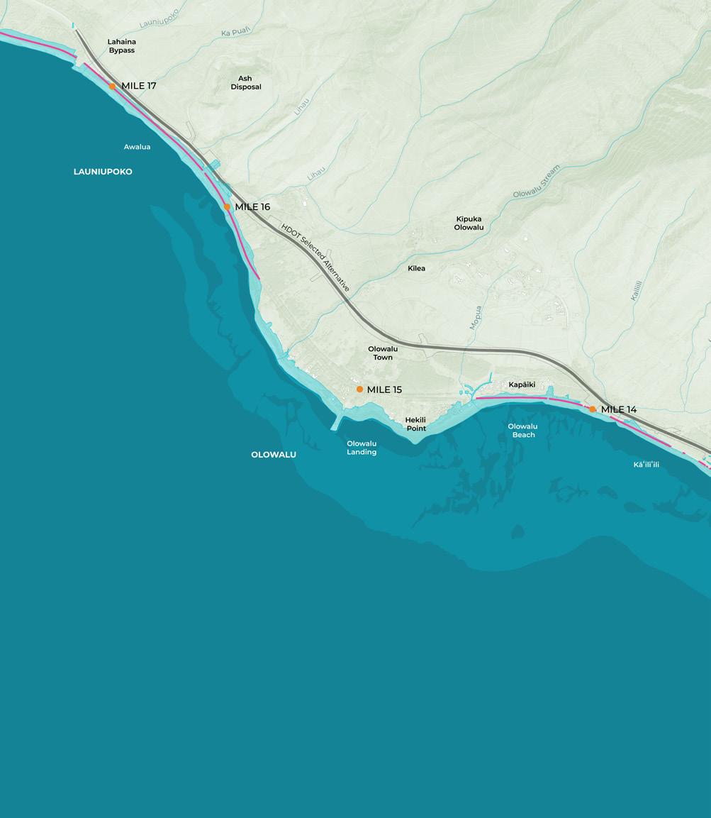
Under the 3.2-ft sea level rise scenario, exposure extends further inland and becomes more persistent across the coastal corridor. Areas that experience episodic flooding under near-term conditions transition toward chronic inundation, while shoreline erosion contributes to the loss and reconfiguration of coastal land. These changes reflect the interaction of multiple hazard processes, including passive flooding, annual high-wave flooding, coastal erosion, and rising groundwater levels as represented in the SLR-XA (Hawaiʻi Climate Change Mitigation and Adaptation Commission 2022).
At this stage, exposure fundamentally alters how portions of the project area can function, requiring long-term adaptation strategies that accommodate sustained inundation, shifting shorelines, and changing access conditions.
For critical infrastructure, current state climate guidelines recommend planning for a 6-foot sea level rise benchmark combined with local flood elevations and additional freeboard (as an added safety margin). Given the long timeframe of this visioning work—at the catalytic site scale—Olowalu: The Road to Resilience recommends and, in long-term conceptual isometric transects, section perspectives, and eye-level renderings, depicts all important, proposed new assets and infrastructure elements, such as built structures in near-shore locations, the elevated multi-use path, which also serves as an additional emergency evacuation route, to be elevated to a height of 15 feet above existing sea level.
Proposed Catalytic Sites
0’ 2,000’ 4,000’
SCALE: 1” = 2,000’ (if printed on 11”x17”)
Catalytic Site 1
Catalytic Site 2
Olowalu Town Mile Marker 14
Catalytic Sites as Strategic Interventions
Based on project area scale sea level rise projection analysis, areas of concentrated exposure were identified as priority locations for targeted design intervention. These areas were selected based on their vulnerability under both the 1.1-ft and 3.2-ft Sea Level Rise Exposure Area (SLR-XA) scenarios, as well as their role in shaping access, ecological function, and public use across the Olowalu–Ukumehame coastal corridor.
These locations are designated as catalytic sites. Each site represents a portion of the coastline where sea level rise and/or highway relocation impacts are most pronounced and where targeted interventions have the potential to influence system performance from mauka to makai. By focusing on these areas, the project moves from corridor-scale analysis to site-specific design opportunities.
At this scale, the catalytic sites establish a network of key nodes distributed along the corridor. Together, they structure a framework for prioritizing intervention, strengthening coastal connectivity, and guiding phased implementation over time.
Catalytic Site 3
Ukumehame Beach Park & Wetlands
Chapter 6 presents Olowalu: The Road to Resilience’s proposed overall project area scale proof-of-concept design through near-term and long-term vision frameworks, illustrating how prioritized interventions and design strategies respond to projected sea level rise conditions over time.
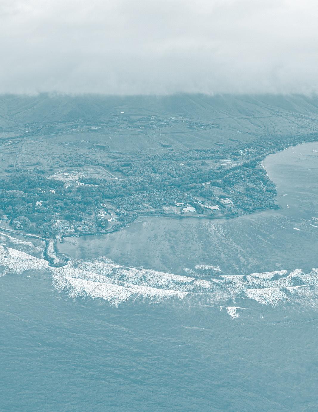
Aerial Image of Olowalu and surrounding west Maui context (TNC, March 15, 2026)
Project Area Scale Plans
This subchapter summarizes the project area scale proof-of-concept design, illustrating how the design framework is applied across the Olowalu-Ukumehame corridor. A series of maps documents existing conditions, projected changes, and the spatial distribution of design strategies.
Existing conditions mapping establishes the project area’s baseline environmental, cultural, and infrastructural systems, particularly the planned highway realignment. Sea level rise projections, based on SLR-XA scenarios at 1.1 and 3.2 feet, identify areas of exposure and inform where adaptation strategies are required.
These analyses guide the development of near-term and long-term vision frameworks, which organize proposed interventions based on timing, community priorities, and projected environmental conditions. Together, these maps demonstrate how the design evolves over time while maintaining continuity across ecological systems, access networks, and cultural landscapes.
Maps included in this section: Existing Conditions
1.1’ SLR-XA Projections
Near-Term Vision with 1.1’ SLR-XA Overlay (Approx. 2045)
Near-Term Vision (Approx. 2045)
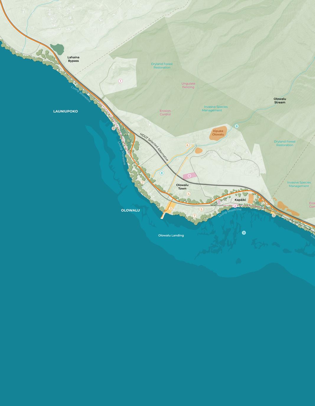
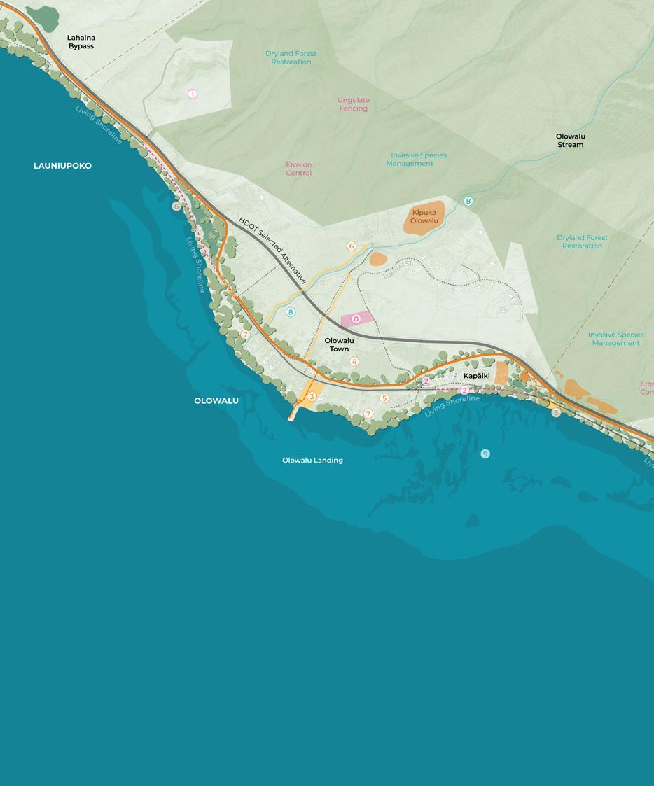
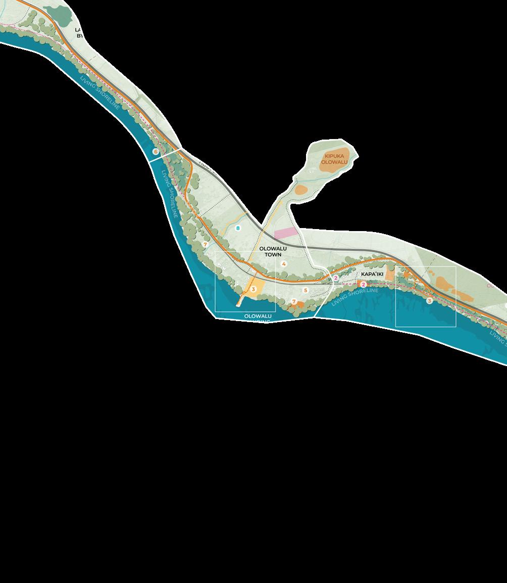
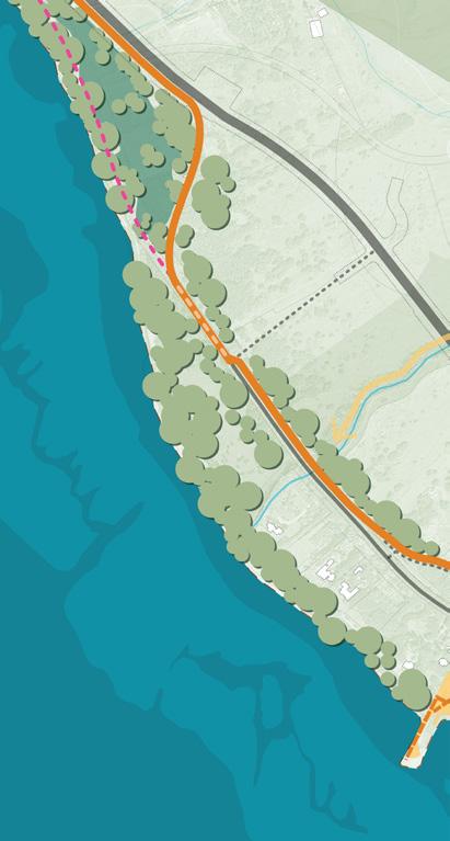
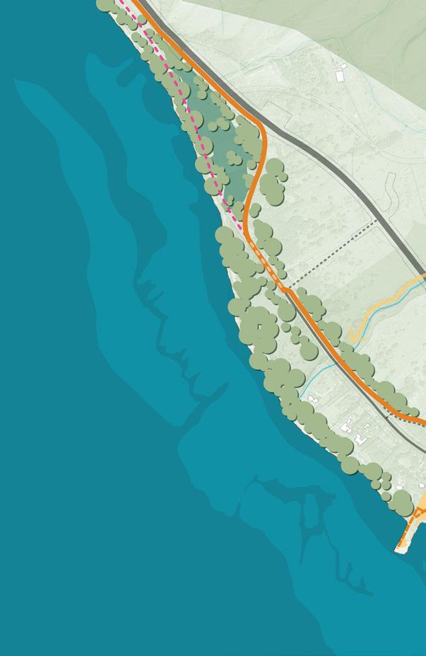
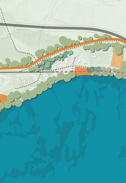
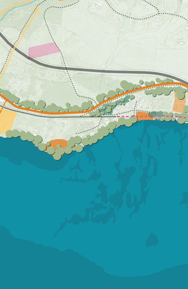
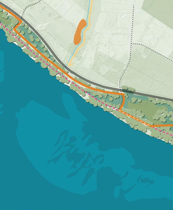
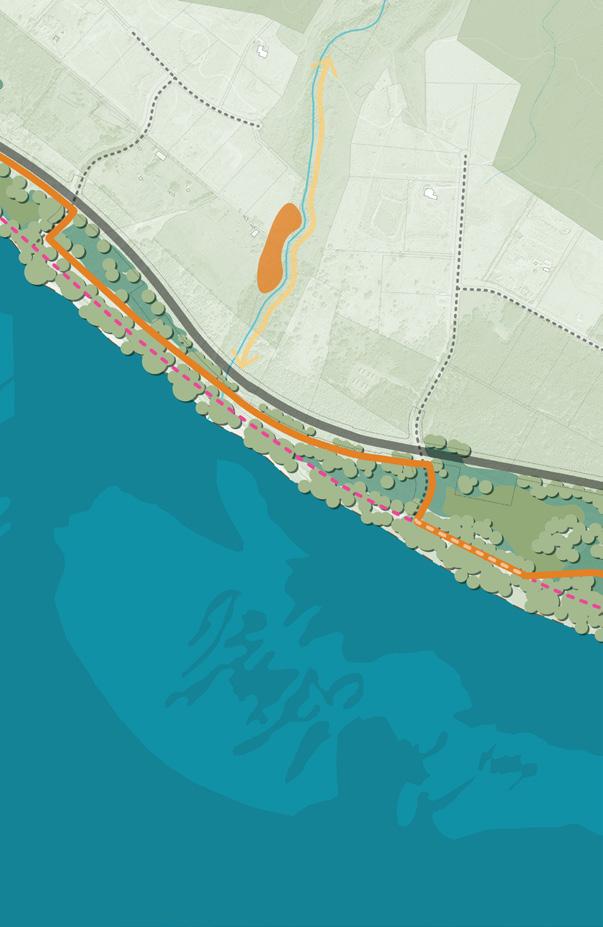
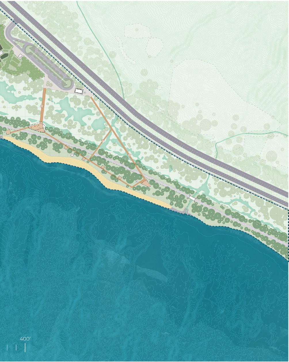
Near-Term Vision Olowalu Segment
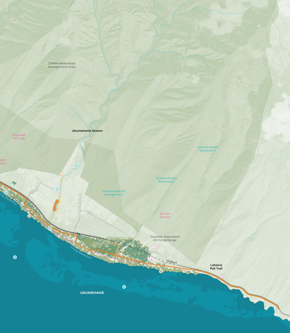
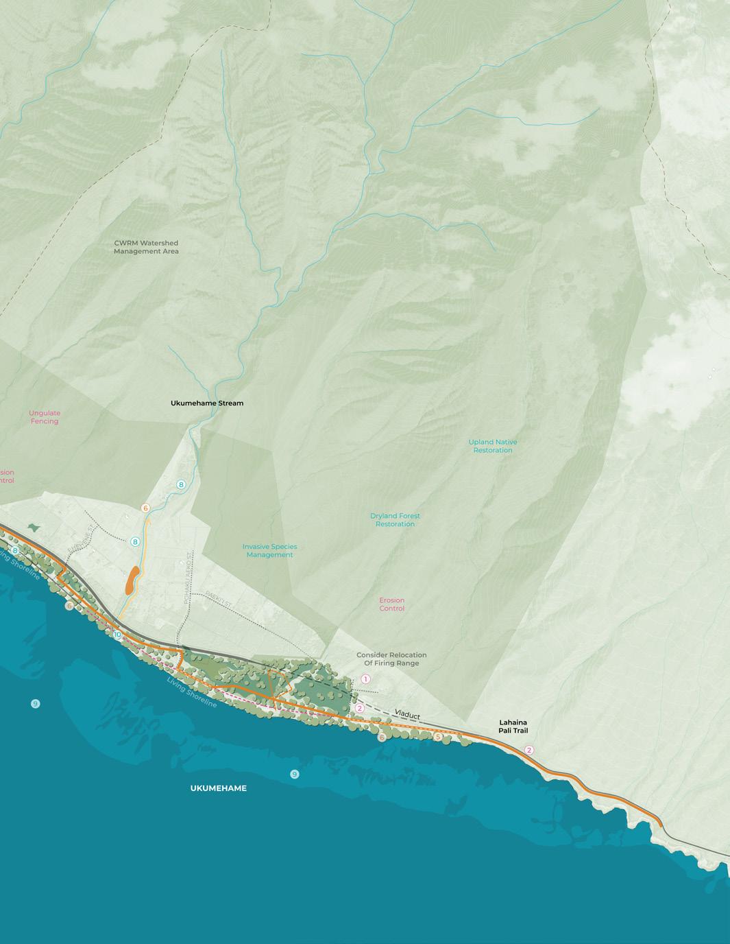
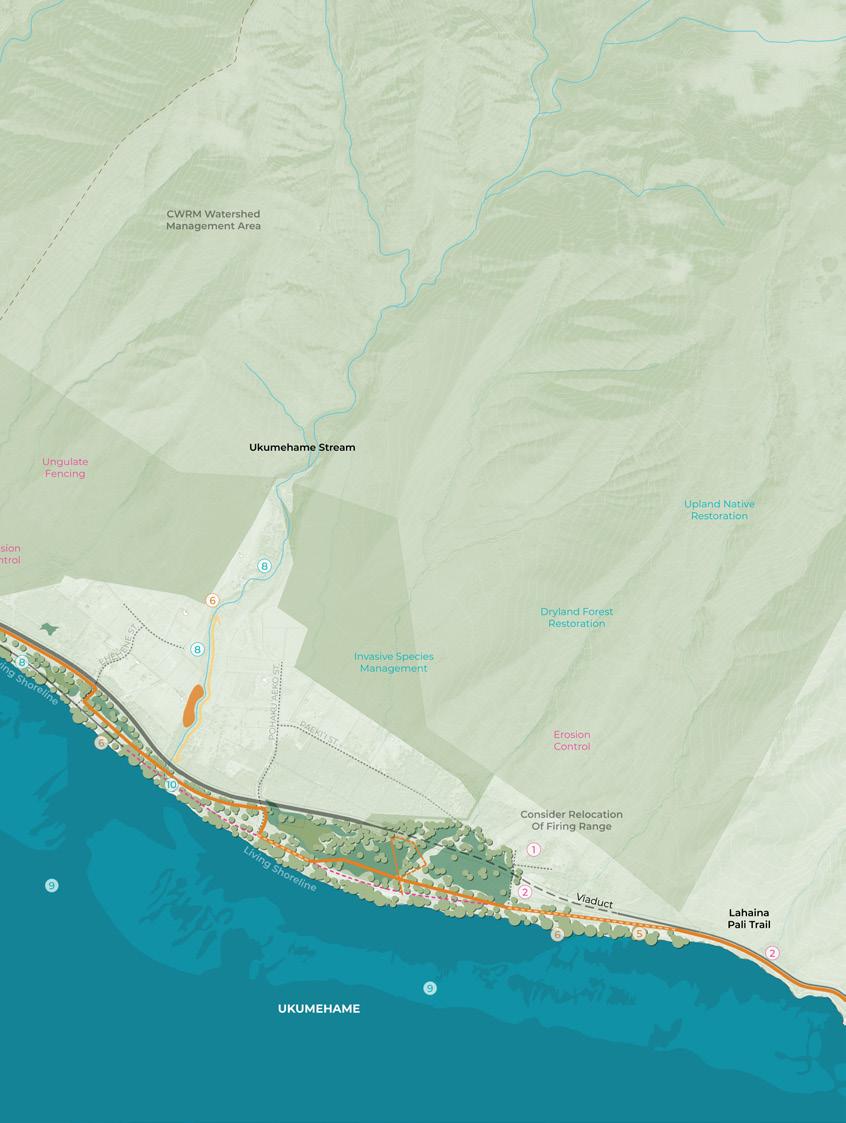
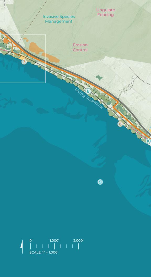
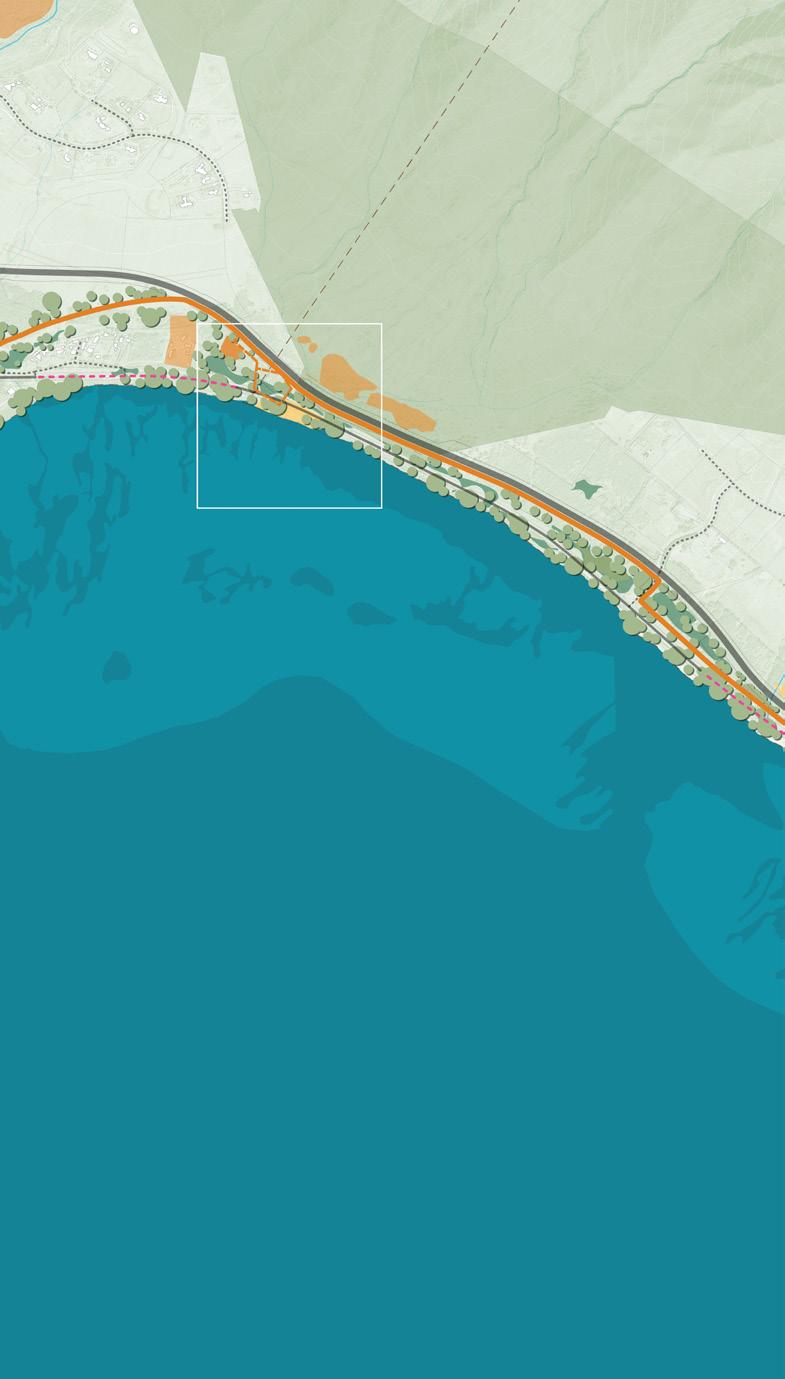
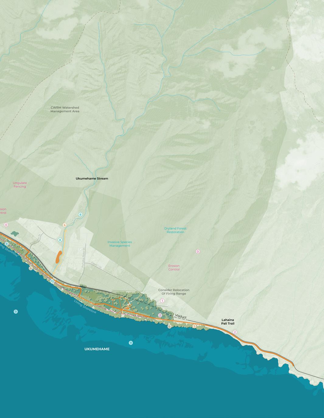
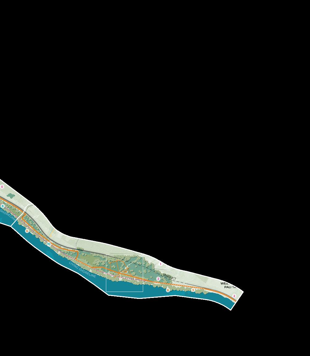
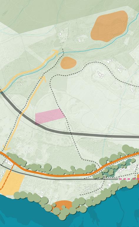
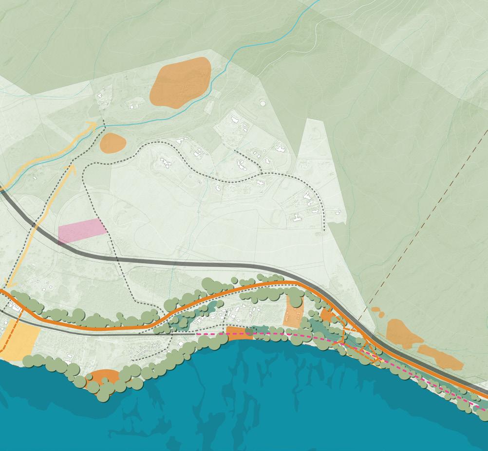
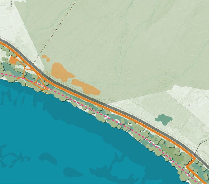
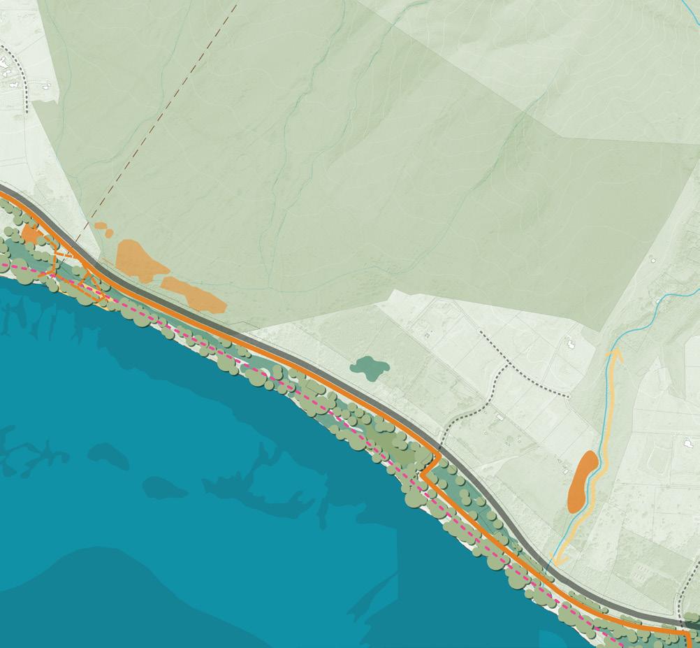
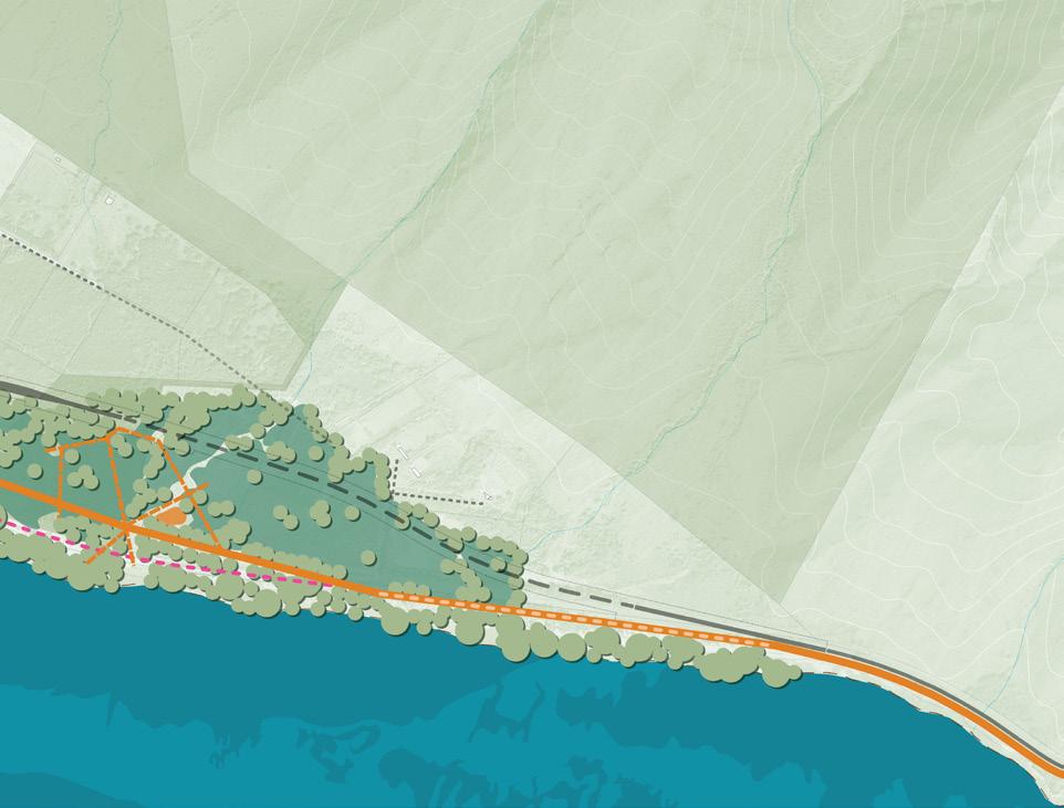
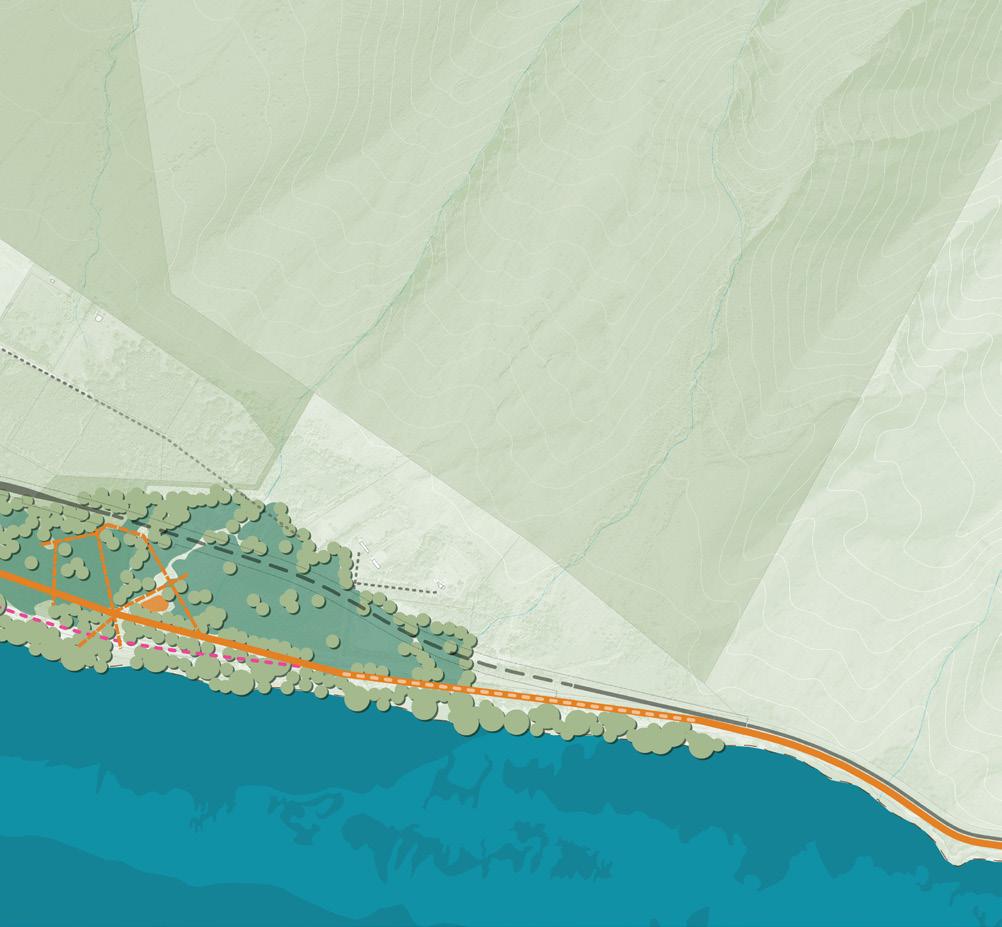
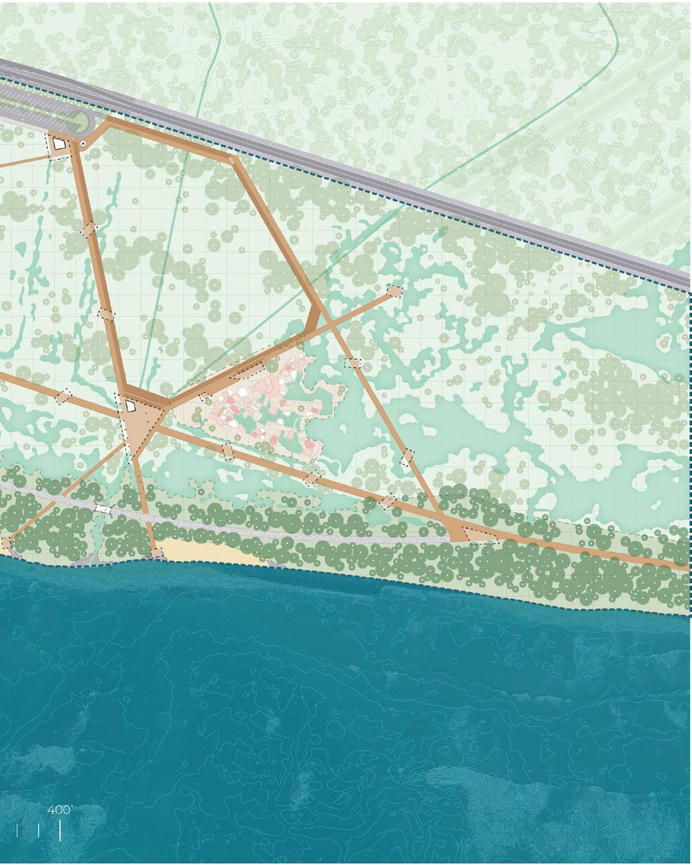
Near-Term Vision Ukumehame Segment
3.2’ SLR-XA Projections
Long-Term Vision with 3.2’ SLR-XA Overlay (Approx. 2075)
Long-Term Vision (Approx. 2075)
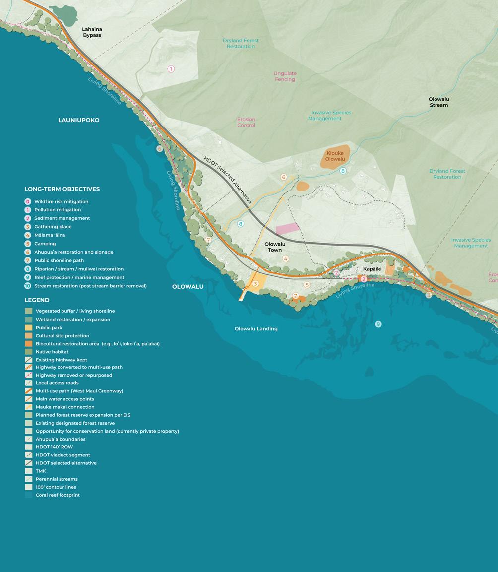
Long-Term Vision: Olowalu Segment
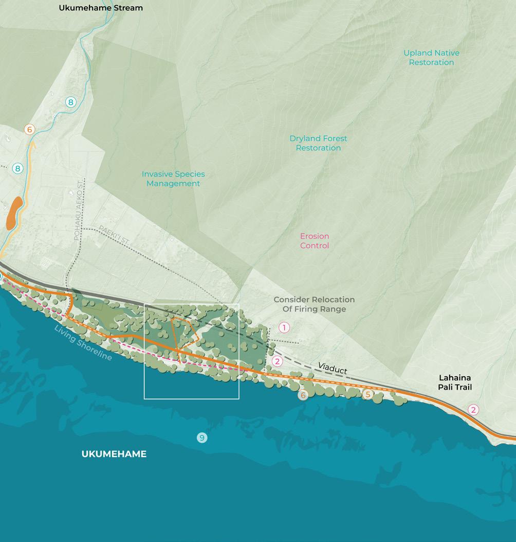
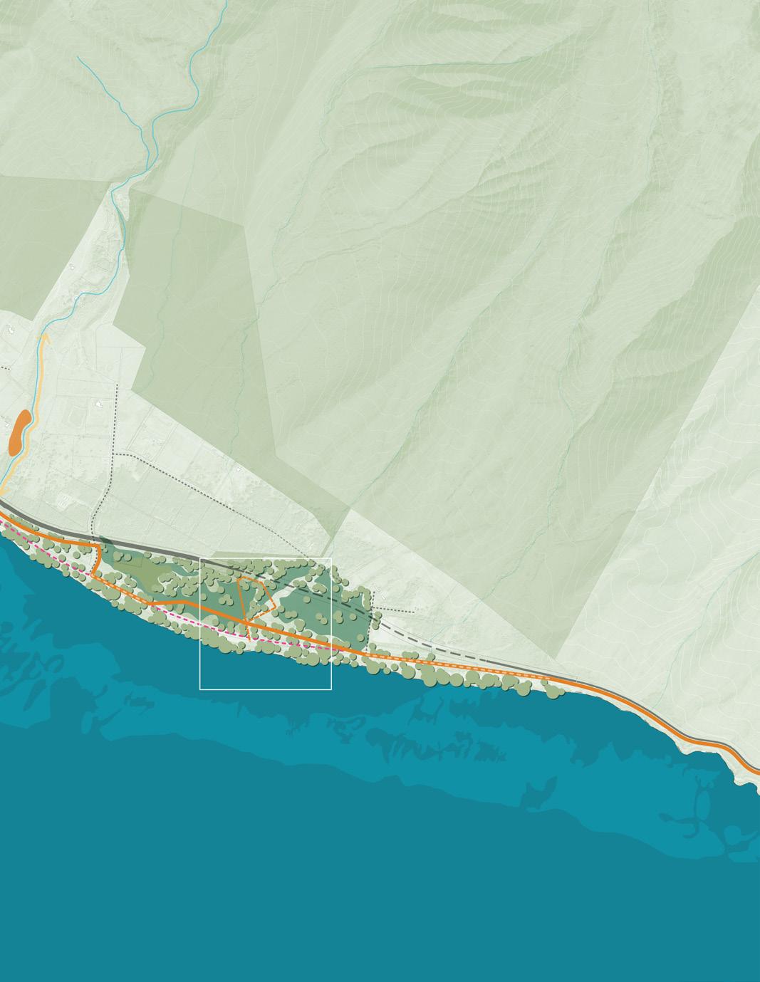
Long-Term Vision Ukumehame Segment
PROJECT AREA SCALE PLANS
Existing Conditions
LEGEND
HDOT 140’ ROW
HDOT viaduct segment
HDOT selected alternative
TMK
Perennial streams
100’ contour lines
Coral reef footprint
0’ 2,000’ 4,000’
SCALE: 1” = 2,000’ (if printed on 11”x17”)
PROJECT AREA SCALE PLANS
1.1’ Sea Level Rise Projection - Approximately 2045
LEGEND
Roadways impacted by 1.1’ SLR-XA
Sea level rise exposure area 1.1’ SLR-XA
HDOT 140’ ROW
HDOT viaduct segment
HDOT selected alternative
TMK
Perennial streams
100’ contour lines
Coral reef footprint
0’ 2,000’ 4,000’
SCALE: 1” = 2,000’ (if printed on 11”x17”)
Data source: Pacific Islands Ocean Observing System (PacIOOS) sea level rise data (September, 2024)
PROJECT AREA SCALE PLANS
Near-Term Vision With 1.1’ SLR-XA Overlay - Approximately 2045 (Inaction)
0’ 2,000’ 4,000’
SCALE: 1” = 2,000’ (if printed on 11”x17”)
PROJECT AREA SCALE PLANS
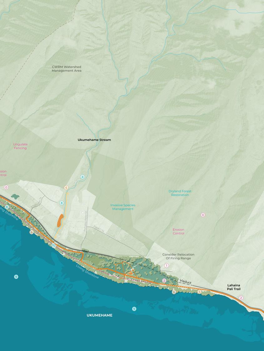
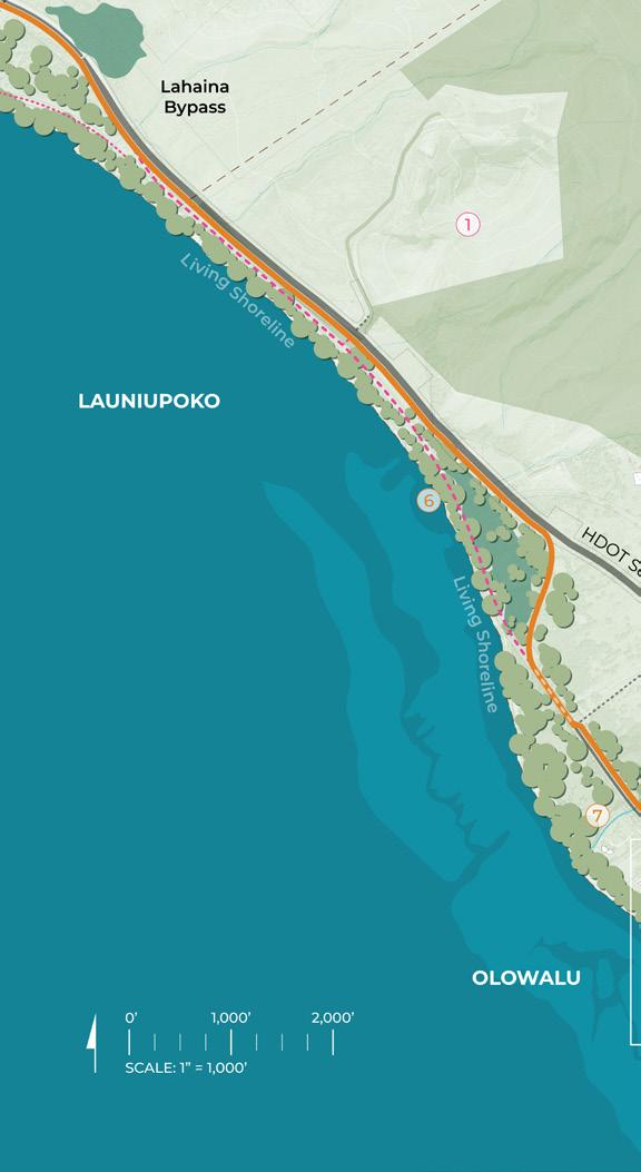
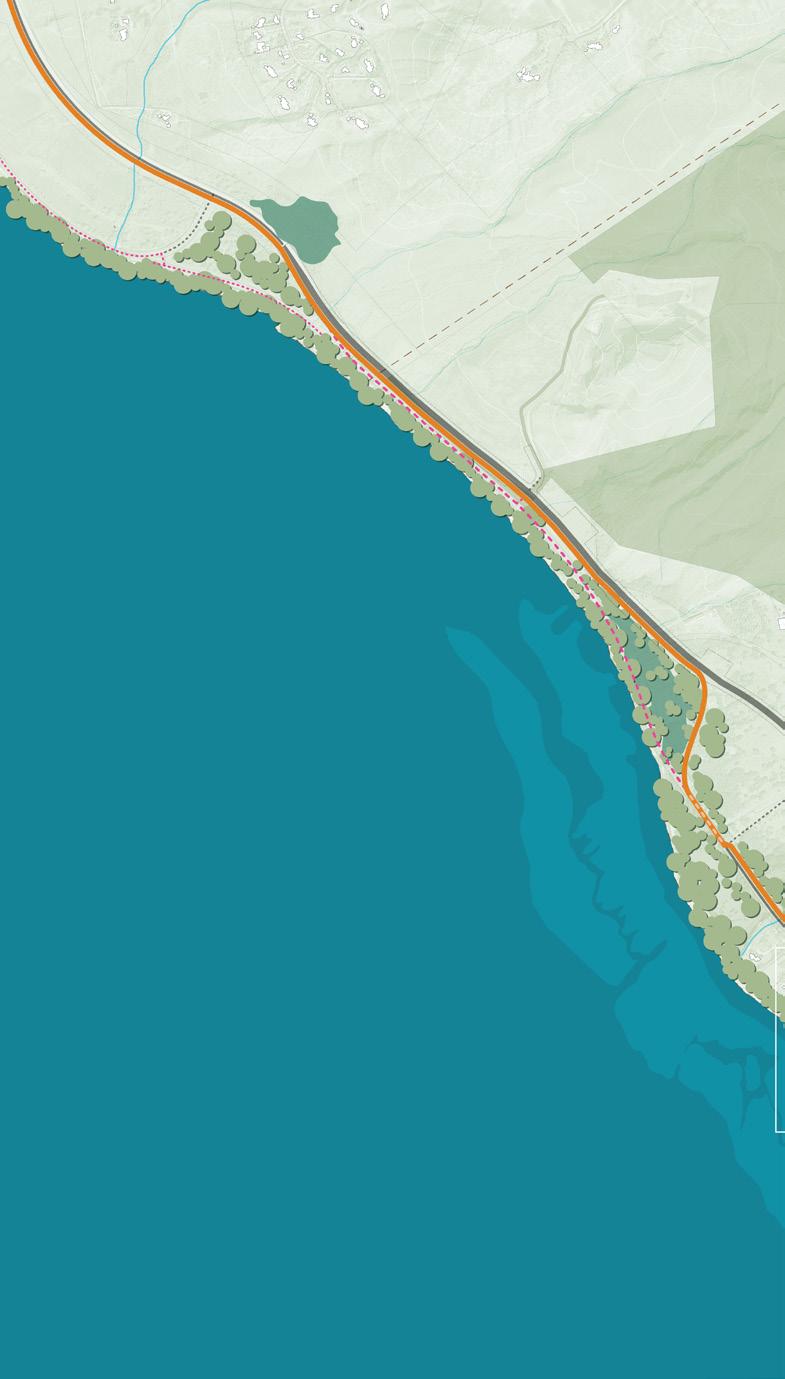
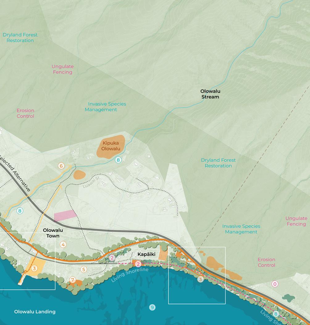
Near-Term Vision - Approximately 2045
0’ 2,000’ 4,000’
SCALE: 1” = 2,000’ (if printed on 11”x17”)
Near-Term
Zoom-In 1
OLOWALU SEGMENT
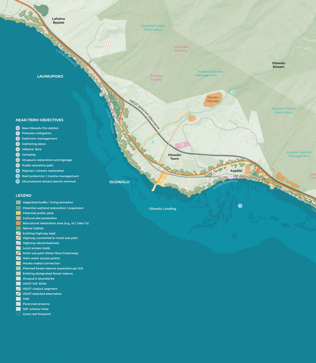
As mentioned above, the visions for the overall project area presented in this report chapter are intended to spatially identify opportunities for proposed conceptual, broad-stroke interventions. These proof-of-concept designs are based on the timing of anticipated environmental conditions and climate threats (such as flooding and coastal erosion), other site analysis findings, and community preferences.
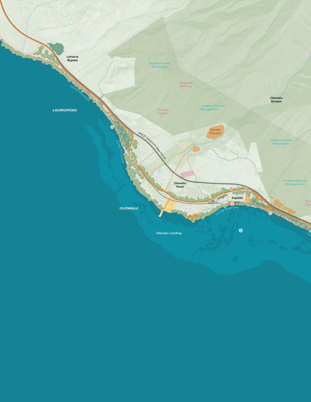
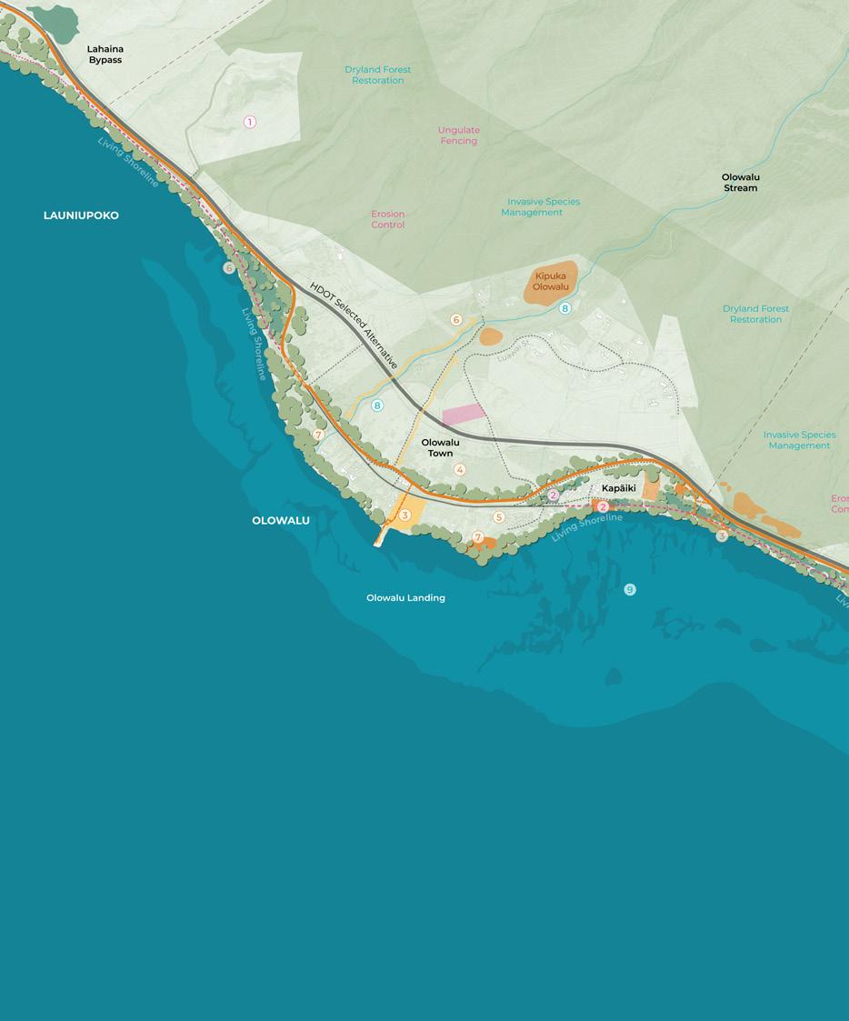
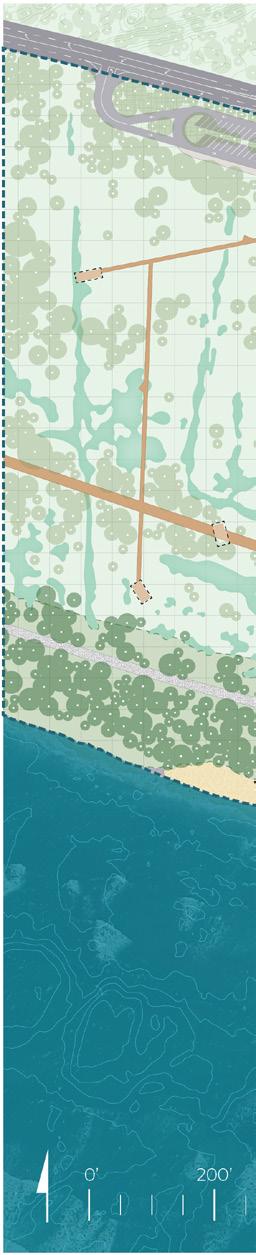
This near-term conceptual vision framework responds to the anticipated effects of 1.1 feet of sea level rise, specifically taking into account the projected sea level rise exposure area. It illustrates the spatial distribution of main design strategies and proposed programs. Proposed key interventions include mitigating pollution, erosion, and manage sediment, initiating habitat and wetland restoration efforts in appropriate areas, initial work towards creating nature-based living shoreline adaptation solutions and vegetated coastal buffers, partial highway decommissioning (where necessary in the near-term), as well as initial steps towards establishing a continuous multi-use path (West Maui Greenway).
Zoom-In 2
The following four report pages include enlarged, zoomed-in versions of the near-term overall project area vision (response to anticipated 1.1-ft SLRXA effects, expected around 2045 for purposes of this project, following highway relocation).
Dividing the plan drawing for the approximately 6-mile-long overall coastal project corridor into two segments allows for easier legibility of proposed interventions, main conceptual design strategies, and their spatial distribution.
The first enlarged project segment, immediate following, focuses on the area around Olowalu. The subsequent zoomed-in plan drawing portion focuses on Ukumehame.
PROJECT AREA SCALE PLANS
NEAR-TERM OBJECTIVES
New Olowalu fire station
Pollution mitigation
Sediment management
Gathering place
Mālama ʻāina
Camping
Ahupuaʻa restoration and signage
Public shoreline path
Riparian / stream restoration
Reef protection & marine management
Ukumehame stream barrier removal
Vegetated buffer / living shoreline
Potential wetland restoration / expansion
Potential public park
Cultural site protection
Biocultural restoration area
Native habitat
Existing highway kept
Highway converted to multi-use path
Highway decommissioned
Local access roads
Multi-use path (West Maui Greenway)
Main water access points
Mauka makai connection
Planned forest reserve expansion per EIS
Existing designated forest reserve
Ahupuaʻa boundaries
HDOT 140’ ROW
HDOT viaduct segment
HDOT selected alternative
TMK
Perennial streams
100’ contour lines
Coral reef footprint
Opportunity for conservation land (currently private property)
OLOWALU SEGMENT
Catalytic Site 1
Catalytic Site 2
PROJECT AREA SCALE PLANS
NEAR-TERM OBJECTIVES
New Olowalu fire station
Pollution mitigation
Sediment management
Gathering place
Mālama ʻāina
Camping
Ahupuaʻa restoration and signage
Public shoreline path
Riparian / stream restoration
Reef protection & marine management
Ukumehame stream barrier removal
Vegetated buffer / living shoreline
Potential wetland restoration / expansion
Potential public park
Cultural site protection
Biocultural restoration area
Native habitat
Existing highway kept
Highway converted to multi-use path
Highway decommissioned
Local access roads
Multi-use path (West Maui Greenway)
Main water access points
Mauka makai connection
Planned forest reserve expansion per EIS
Existing designated forest reserve
Ahupuaʻa boundaries
HDOT 140’ ROW
HDOT viaduct segment
HDOT selected alternative
TMK
Perennial streams
100’ contour lines
Coral reef footprint
Opportunity for conservation land (currently private property)
Catalytic Site 2
UKUMEHAME SEGMENT
Catalytic Site 3
PROJECT AREA SCALE PLANS
3.2’ Sea Level Rise Projection - Approximately 2075
LEGEND
Roadways impacted by 3.2’ SLR-XA
Sea level rise exposure area 3.2’ SLR-XA
HDOT 140’ ROW
HDOT viaduct segment
HDOT selected alternative
TMK
Perennial streams
100’ contour lines
Coral reef footprint
0’
2,000’ 4,000’
SCALE: 1” = 2,000’ (if printed on 11”x17”)
Data source: Pacific Islands Ocean Observing System (PacIOOS) sea level rise data (September, 2024)
PROJECT AREA SCALE PLANS
Long-Term Vision With 3.2’ SLR-XA Overlay - Approximately 2075 (Inaction)
0’ 2,000’ 4,000’
SCALE: 1” = 2,000’ (if printed on 11”x17”)
PROJECT AREA SCALE PLANS
Long-Term Vision - Approximately 2075
0’ 2,000’ 4,000’
SCALE: 1” = 2,000’ (if printed on 11”x17”)
Long-Term Vision - Approximately 2075
Zoom-In 1
OLOWALU SEGMENT
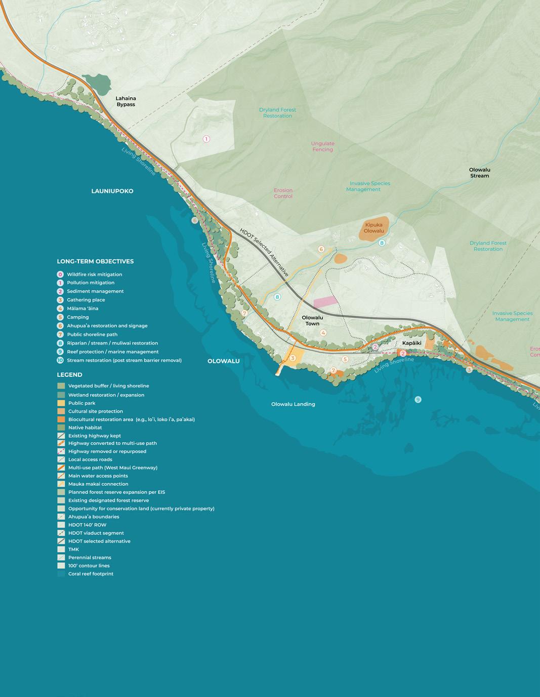
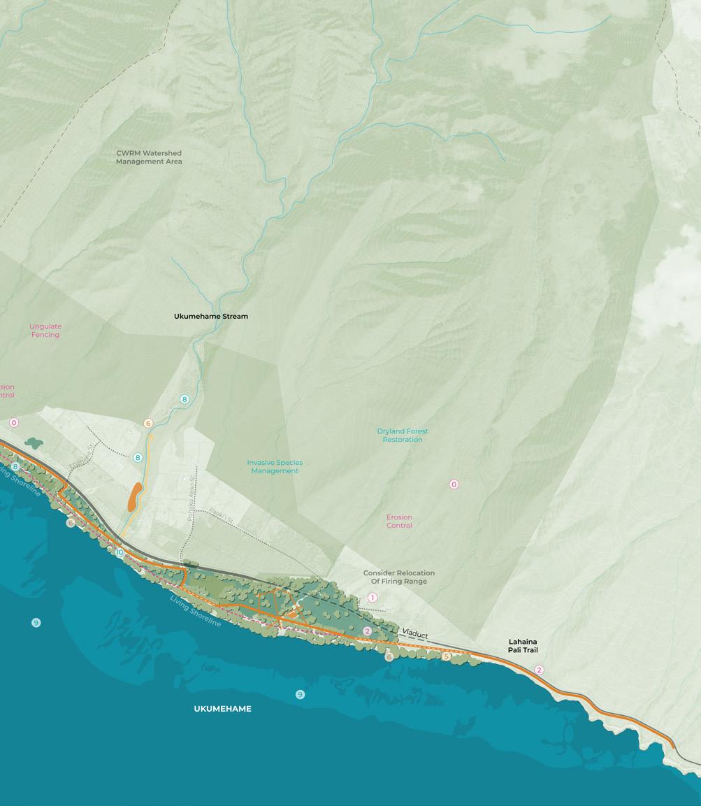
The conceptual visions for the overall project area presented in this report chapter are intended to spatially identify opportunities for proposed broadstroke interventions. These proof-of-concept designs are based on the timing of anticipated environmental conditions and climate threats (such as flooding and coastal erosion), other site analysis findings, and community preferences.
This long-term conceptual vision framework responds to the anticipated effects of 3.2 feet of sea level rise, specifically taking into account the projected sea level rise exposure area. It illustrates the spatial distribution of main future design strategies and programs.
Proposed interventions include continued erosion and sediment management through nature-based solutions, further native habitat and wetland restoration, completing work towards a continuous, layered living shoreline and vegetated coastal buffer, biocultural restoration, continued highway decommissioning and removal (where necessary in the longer term), as well as completing a continuous multi-use path connecting coastal open spaces and providing public non-automobile access.
The following four report pages include enlarged, zoomed-in versions of the long-term overall project area vision (response to anticipated 3.2-ft SLR-XA effects, expected around 2075 for purposes of this project).
Dividing the plan drawing for the approximately 6-mile-long overall coastal project corridor into two segments allows for easier legibility of proposed long-term interventions, main conceptual design strategies, and their spatial distribution.
The first enlarged project segment, immediate following, focuses on the area around Olowalu. The subsequent zoomed-in plan drawing portion
LONG-TERM OBJECTIVES
Wildfire risk mitigation
Pollution mitigation
Sediment management
Gathering place
Mālama ʻāina
Camping
Ahupuaʻa restoration and signage
Public shoreline path
Riparian / stream / muliwai restoration
Reef protection & marine management
Stream restoration (post stream barrier removal)
Vegetated buffer / living shoreline
Wetland restoration / expansion
Public park
Cultural site protection
Native habitat
Existing highway kept
Highway converted to multi-use path
Highway removed or repurposed
Local access roads
Multi-use path (West Maui Greenway)
Main water access points
Mauka makai connection
Planned forest reserve expansion per EIS
Existing designated forest reserve
Ahupuaʻa boundaries
HDOT 140’ ROW
HDOT viaduct segment
HDOT selected alternative
TMK
Perennial streams
100’ contour lines
Coral reef footprint
Biocultural restoration area (e.g., loʻi, loko iʻa, paʻakai)
for conservation land (currently private property)
OLOWALU SEGMENT
Catalytic Site 1
Catalytic Site 2
LONG-TERM OBJECTIVES
Wildfire risk mitigation
Pollution mitigation
Sediment management
Gathering place
Mālama ʻāina
Camping
Ahupuaʻa restoration and signage
Public shoreline path
Riparian / stream / muliwai restoration
Reef protection & marine management
Stream restoration (post stream barrier removal)
Vegetated buffer / living shoreline
Wetland restoration / expansion
Public park
Cultural site protection
Native habitat
Existing highway kept
Highway converted to multi-use path
Highway removed or repurposed
Local access roads
Multi-use path (West Maui Greenway)
Main water access points
Mauka makai connection
Planned forest reserve expansion per EIS
Existing designated forest reserve
Ahupuaʻa boundaries
HDOT 140’ ROW
HDOT viaduct segment
HDOT selected alternative
TMK
Perennial streams
100’ contour lines
Coral reef footprint
Biocultural restoration area (e.g., loʻi, loko iʻa, paʻakai)
Opportunity for conservation land (currently private property)
Catalytic Site 2
UKUMEHAME SEGMENT
Catalytic Site 3
Chapter 7 features conceptual near-term and long-term visions for Catalytic Site 1, the area around Olowalu Town and Landing.
The speculative site-scale design interventions proposed for this location focus on placemaking, community, and improved public waterfront access, while incorporating sea level rise adaptation strategies and improved ecosystem services.
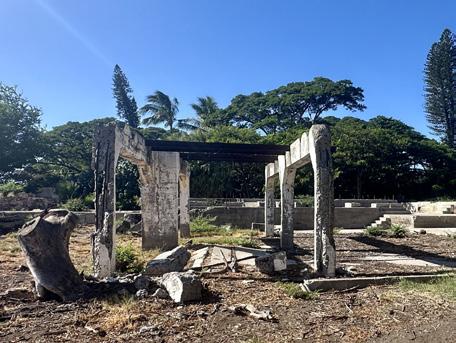
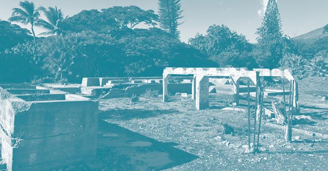
Olowalu sugar mill remnants (UHCDC, 2024)
Background
This section of the report provides a high-level overview of several of the most significant features within Catalytic Site 1. Through multiple in-person site visits, along with engagement with stakeholders and members of the local community, the project team developed a comprehensive understanding of the site’s existing conditions and the significance of its various features within the broader project context.
While this overview does not encompass every feature, it highlights several of the site’s most prominent and frequently referenced elements. Additional details and discussion of each feature are provided on the following pages.
Listed Site Features:
Honoapiʻilani Highway
Gravel Parking Lot
Small Businesses
Olowalu Landing
Historical Remnants
Overview
Olowalu Town is a small rural coastal community characterized by low-density development, open coastal landscapes, and a strong connection to the ocean and reef system. The area supports a modest local population and a handful of small businesses serving both residents and visitors traveling through West Maui. These businesses, along with shoreline recreation and fishing activities, contribute to the area’s informal and community-oriented character.
Development in Olowalu remains relatively limited compared to nearby resort areas, giving the town a distinctly rural atmosphere. Small commercial buildings, roadside vendors, and open lots are interspersed along the highway corri-
dor, while the surrounding landscape remains largely undeveloped. Daily activity often centers on ocean access, local commerce, and travelers stopping briefly along the coastal route.
The existing Honoapiʻilani Highway strongly influences how people experience and move through the area. Vehicle circulation, informal parking, and limited pedestrian infrastructure shape shoreline access and local activity patterns. As transportation infrastructure evolves, Olowalu Town presents opportunities to strengthen its role as a small coastal community while maintaining its rural scale and focus on local businesses.
Local business at Olowalu Town (UHCDC, 2024)
Existing Site Features
The following categories provide an overview of the existing features found within and surrounding Olowalu Town. Understanding these conditions helps establish the site’s current character, opportunities, and constraints.
Honoapiʻilani Highway
The roadway carries steady regional traffic that shapes movement and access within the area. Pedestrian infrastructure along this segment is limited, making it difficult to safely cross between mauka areas and shoreline destinations such as Olowalu Landing. Improved crossings and pedestrian infrastructure could strengthen connections between the town and the coast. Roadway edges and median areas may also provide opportunities for landscape interventions such as vegetated swales or other forms of green infrastructure that support stormwater management and sediment control, while enhancing the corridor’s environmental performance.
Gravel Parking Lot
An informal parking area currently provides access for visitors stopping in Olowalu Town. The space lacks defined stalls or circulation patterns, and vehicles typically park wherever space is available before walking to nearby businesses, shoreline destinations, and gathering areas. While the lot offers convenient access, its open layout limits efficient use of space and creates a visually sparse condition within the town. A more defined parking layout that incorporates green stormwater infrastructure could help organize circulation, control polluted runoff, and improve the overall appearance of this arrival point while maintaining flexible access for residents and visitors.
Small Businesses
A small cluster of local businesses contributes
Mile Marker 15 along existing highway (UHCDC, 2024)
Parking lot at Olowalu Town (UHCDC, 2024)
Olowalu General Store (UHCDC, 2024)
to the character of Olowalu Town and provides services for residents and travelers along the West Maui coast. Establishments such as Leoda’s Kitchen and Pie Shop and the Olowalu General Store serve as recognizable stops along the highway and help create a sense of place within the rural community. A nearby farmers market area also provides space for local vendors and seasonal activity, supporting small-scale commerce and community gathering. Preserving these spaces helps maintain the town’s local identity and community-centered character.
Olowalu Landing
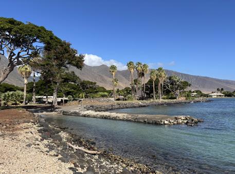
Activity and public waterfront access in the area of the landing are limited, with most visitors consisting of local fishermen or residents familiar with the nearby swimming area. With cleanup and thoughtful site improvements, Olowalu Landing has the potential to become a welcoming community hub and shoreline park. Reusing portions of the existing foundations for new infrastructure could help preserve the site’s historic character while creating spaces that invite residents and visitors to gather, learn about the area’s history, and reconnect with the coast.
Historical Remnants
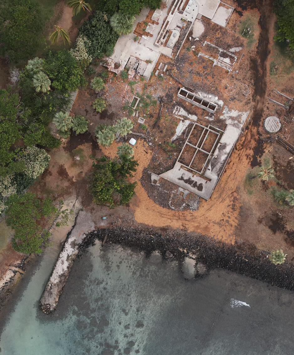
Catalytic Site 1 includes a historic preservation site with remnants of the Olowalu Mill from the sugar plantation era. Portions of concrete foundations are still visible across the site. Today, much of the area includes crumbled remnants, exposed rebar, and other debris scattered among patches of grass, dirt, and rocky shoreline. Despite these conditions, the site remains historically significant and is designated as a protected area tied to Olowalu’s plantation history. The remaining foundations and structural remnants provide a physical record of the site’s past and offer opportunities to interpret and share this history with the community.
Water access at Olowalu Landing (UHCDC, 2024)
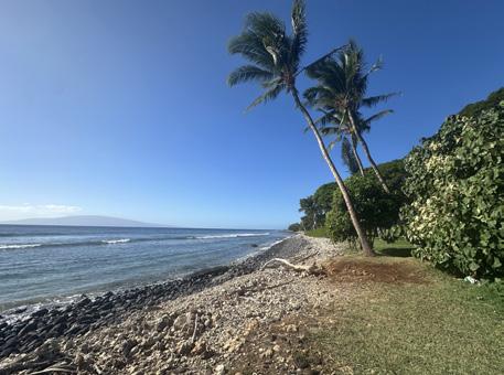
Coastline at Olowalu Landing (UHCDC, 2024)
Sugar mill remnants (UHCDC, 2024)
Aerial image of Olowalu Landing area including sugar mill remnants (TNC, 2024)
Honoapiʻilani Highway near Olowalu Town (UHCDC, 2024)
Analysis
The following report pages feature a set of seven thematic site inventory and analysis maps, represented at the zoomed-in catalytic site scale, each covering a square area dimensioned 2,000-ft by 2,000-ft.
These maps spatially visualize select site conditions, program elements, and opportunities and constraints that have informed conceptual proof-of-concept design decisions for Catalytic Site 1.
List of Analysis Maps:
Existing Conditions (2026)
Wetland and Habitat
Hydrology and Topography
Land Ownership
Shoreline and Coastal Conditions
1.1’ Sea Level Rise Exposure Area (Approximately 2045)
3.2’ Sea Level Rise Exposure Area (Approximately 2075)
EXISTING CONDITIONS
Analysis map legend outlined below:
Parking lot
Honoapiʻilani Highway
Existing Olowalu Town buildings
Sugar Mill remnants
Olowalu landing
Olowalu Town market space
Sugar mill remnants at Olowalu (UHCDC, 2024)
Honoapiʻilani Highway at Olowalu (UHCDC, 2024)
ANALYSIS
Catalytic Site 1 Proof-of-Concept Design
WETLAND AND HABITAT
Analysis map legend outlined below:
Building footprints
Existing wetlands
Potential wetlands
Wetlands 100’ buffer
Wetland data adapted from Maui County Wetland Overlay Map (2024).
Existing vegetation and habitat at Olowalu Landing (UHCDC, 2024)
Location of potential wetlands in Olowalu (UHCDC, 2025)
POTENTIAL WETLANDS
HONOAPIʻILANIHWY
OLOWALU LANDING
OLOWALU CANE HAUL RD.
ANALYSIS
Catalytic Site 1 Proof-of-Concept Design
HYDROLOGY & TOPOGRAPHY
Analysis map legend outlined below:
5’ contour lines
1’ contour lines Ditches Gulches
Olowalu: The Road
Olowalu stream (UHCDC, 2024)
Mauka view from Olowalu Landing (UHCDC, 2024)
OLOWALU LANDING
OLOWALU CANE HAUL RD.
HONOAPIʻILANIHWY
ANALYSIS
Catalytic Site 1 Proof-of-Concept Design
LAND OWNERSHIP
Analysis map legend outlined below:
Building footprints
TMK parcel lines
Private landowner
State of Hawaiʻi
County of Maui
Private residences near Olowalu Town (UHCDC, 2025)
Olowalu General Store (UHCDC, 2024)
OLOWALU LANDING
OLOWALU CANE HAUL RD.
HONOAPIʻILANIHWY
ANALYSIS
Catalytic Site 1 Proof-of-Concept Design
SHORELINE & COASTAL CONDITIONS
Analysis map legend outlined below:
Building footprints
Hardened shoreline
Rocky shoreline
Residential conditions
Commercial conditions
Hardened conditions
Historical remnants
Olowalu rocky shoreline (UHCDC, 2024)
Olowalu rocky shoreline (UHCDC, 2024)
KILEA HILL ACCESS RD.
OLOWALU TOWN
OLOWALU LANDING
SUGAR MILL REMNANTS
OLOWALU CANE HAUL RD.
Catalytic Site 1 Proof-of-Concept Design
1.1’ SEA LEVEL RISE EXPOSURE AREA
Analysis map legend outlined below:
Building footprints
On-site sewage disposal
Coastal erosion line
Existing coastline
1.1’ Sea level rise exposure area (approximately 2045)
The Sea Level Rise Exposure Area (SLR-XA) maps the combined footprint of multiple coastal hazards anticipated as a result of sea level rise. SLR-XA modeling includes the following three chronic flooding hazards: passive flooding, annual high wave flooding, and coastal erosion.
For purposes of the Olowalu: The Road to Resilience project, based on NOAA’s current intermediate-high scenario, 1.1 feet of sea level rise are anticipated around 2045. (Also see Chapter 5 above.)
Data source: Pacific Islands Ocean Observing System (PacIOOS) sea level rise data (September, 2024)
KILEA HILL ACCESS RD.
OLOWALU TOWN
OLOWALU LANDING
SUGAR MILL REMNANTS
OLOWALU CANE HAUL RD.
Catalytic Site 1 Proof-of-Concept Design
3.2’ SEA LEVEL RISE EXPOSURE AREA
Analysis map legend outlined below:
Building footprints
On-site sewage disposal
Coastal erosion line
Existing coastline
3.2’ Sea level rise exposure area (approximately 2075)
The Sea Level Rise Exposure Area (SLR-XA) maps the combined footprint of multiple coastal hazards anticipated as a result of sea level rise. SLR-XA modeling includes the following three chronic flooding hazards: passive flooding, annual high wave flooding, and coastal erosion.
For purposes of the Olowalu: The Road to Resilience project, based on NOAA’s current intermediate-high scenario, 3.2 feet of sea level rise are anticipated around 2075. (Also see Chapter 5 above.)
Data source: Pacific Islands Ocean Observing System (PacIOOS) sea level rise data (September, 2024)
KILEA HILL ACCESS RD.
OLOWALU TOWN
OLOWALU LANDING
SUGAR MILL REMNANTS
OLOWALU CANE HAUL RD.
Aerial image of Olowalu Landing area including sugar mill remnants (TNC, 2024)
Site Plans
Following the preceding site analysis, the proof-of-concept design documentation for Catalytic Site 1 begins with plan-view representations of the proposed concepts. Subsequent report pages illustrate a series of sequential design visions that were informed by the results of community and stakeholder engagement, site analysis, and interdisciplinary collaboration with technical experts.
List of Site Plans:
Existing Plan (2026)
Near-Term Plan (Approximately 2045)
Long-Term Plan (Approximately 2075)
Overview
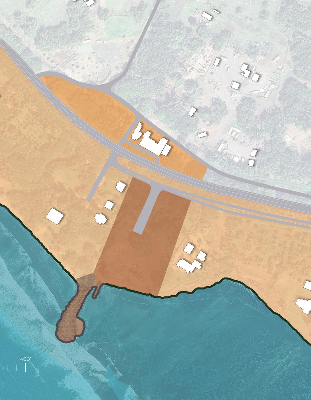
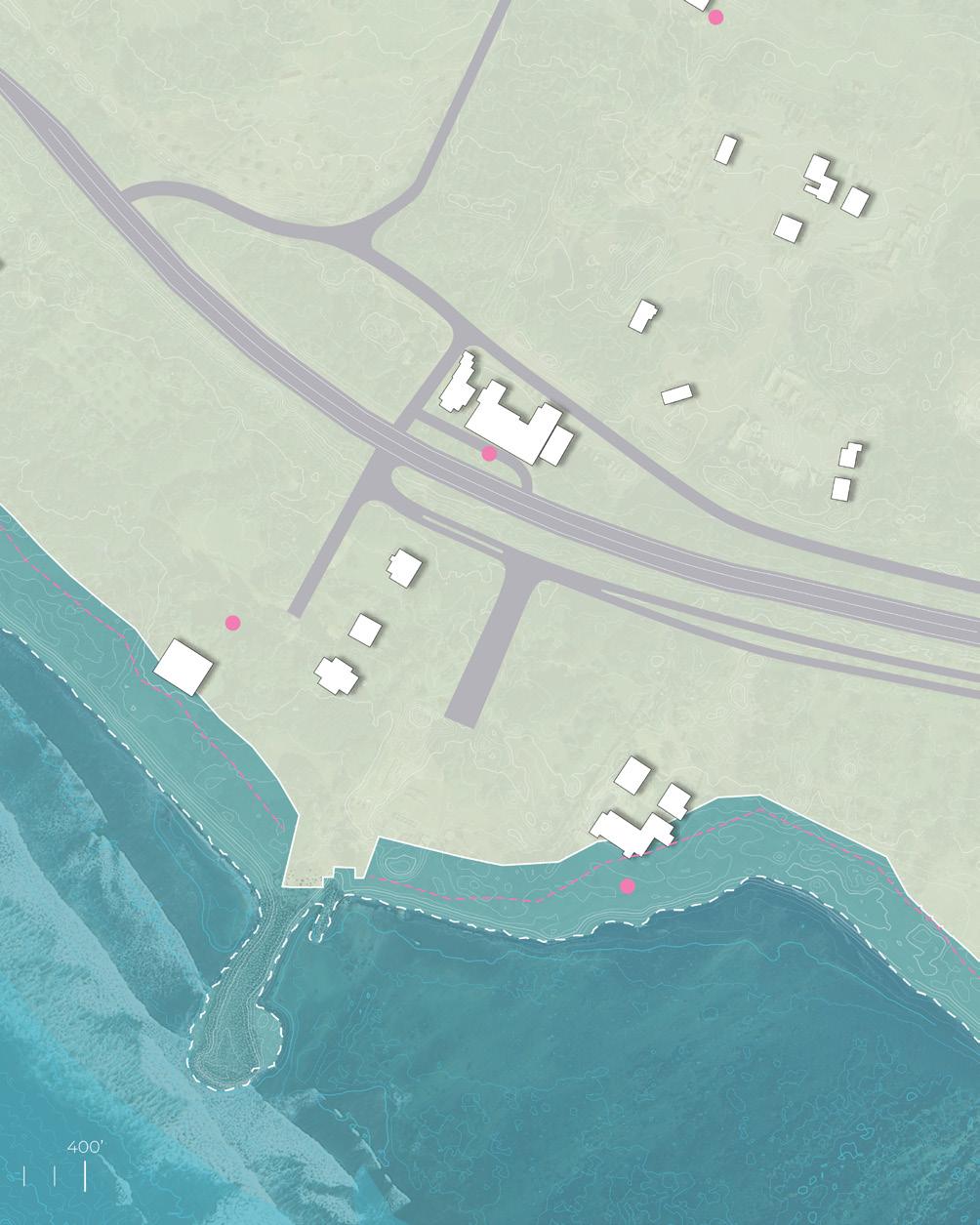
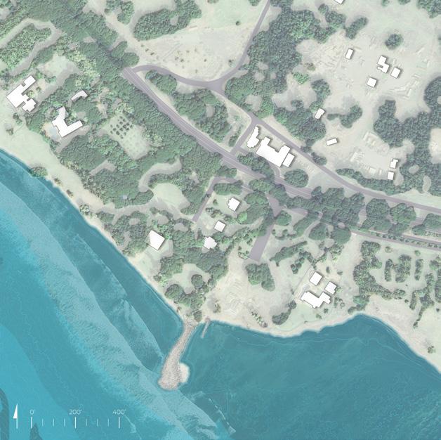
The proposed conceptual design for Catalytic Site 1 is first presented through a series of planview drawings. Each catalytic site is defined by a 2,000-ft by 2,000-ft boundary, allowing the design to focus on the site features and conditions most relevant to the proof-of-concept vision.
The limit of work for Catalytic Site 1 encompasses a diverse range of existing features including the coastline, historic remnants, residential areas, pedestrian activity nodes, and the Honoapiʻilani Highway, which runs through the center of the site.
The location and site extent were informed by site analysis and community engagement to
identify the areas most critical to address within the proof-of-concept design.
The boundary, shown above in the context of existing site conditions, remains consistent across all three design time frames: Existing (2026), Near-Term (approximately 2045), and LongTerm (approximately 2075). As discussed in Chapter 5, the project’s overarching time scale for these proof-of-concept designs is guided by the anticipated Honoapiʻilani Highway relocation schedule and sea level rise projections from NOAA’s 2022 Intermediate High sea level rise scenario for Hawaiʻi.
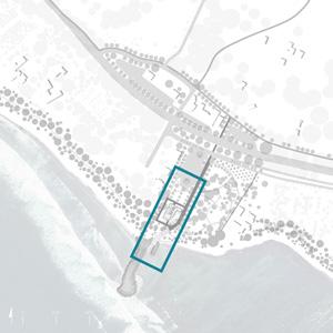
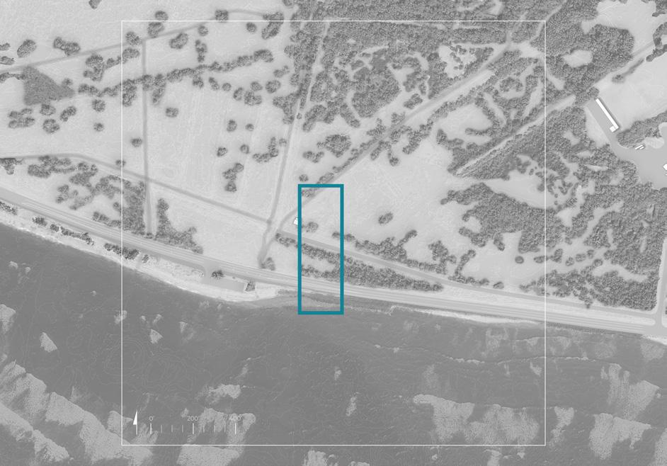
Plan view of Catalytic Site 1 limit of work (UHCDC)
Catalytic Site Limit of Work
Existing Plan
The first part of this chapter summarizes the current site conditions. Existing features establish the site’s physical character while also highlighting several key challenges and opportunities that inform the proof-of-concept design.
Notable site conditions include limited public access to the shoreline due to extensive private land ownership, the proliferation of invasive vegetation, the presence of on-site sewage disposal systems (cesspools), erosion affecting areas containing historic sugar mill remnants, and commercial uses dominated by impervious surfaces. At the same time, the site’s recreational water access and cultural significance reinforce the importance of balancing environmental restoration, public accessibility, and long-term resilience within the proposed design.
Near-Term Plan
The near-term proof-of-concept design for Catalytic Site 1 seeks to incorporate programs and uses related to the overall project goals.
Place and Community
• Connection to the future relocated Honoapiʻilani Highway
• Multi-use path (West Maui Greenway)
• Increased community benefits in the commercial zone
• Possible conversion to park land with the anticipation of a public-private partnership
• Continuous waterfront access
• Adaptive reuse of sugar mill remnants
Ecology and Habitat
• Vegetated buffer and living shoreline
• Bioswales and nature-based solutions along the existing highway
• Native habitat restoration
Climate and Hazards
• Sea level rise adaptation through coastline protection
• Retrofitting sewage systems to sustainable solutions
Long-Term Plan
The long-term proof-of-concept design of Catalytic Site 1 seeks to continue and strengthen the incorporation of programs related to the overall project goals.
Place and Community
• Multi-use path (West Maui Greenway)
• Continue to support commercial use, services (local food and value added products), and community resources
• Creation of a resilience hub
• Public park for community gathering space (Pāka Olowalu)
• Improved recreational water access
• Implementation of the Olowalu Pier
Ecology and Habitat
• Fully developed vegetated buffer and living shoreline
• Cleaned sugar mill remnants become habitat
• Continuation of native habitat restoration
Climate and Hazards
• Sea level rise adaptation through retreat (relocation), nature-based and living systems, and elevated structures
• Sustainable sewage disposal solutions
• Bioswales and nature-based solutions along highway and parking lots
Site Plans Time Frame
Existing: 2026
Near-Term: Approximately 2045 (1.1’ SLR-XA)
Long-Term: Approximately 2075 (3.2’ SLR-XA)
NEAR-TERM PLAN
Approximately 2045
Parking lot
Public shoreline path
Park pedestrian path
Wooden path
Multi-use path (West Maui Greenway)
Paved multipurpose area
Comfort station
Resilience hub
Market stalls
Park pavilions
Pavilion concrete platform and building foundation
Sugar mill remnant remediation and adaptive reuse
Concrete steps
Ramp
Seats and retaining walls
Vegetated buffer and living shoreline
Revetments
LONG-TERM PLAN
Approximately 2075
Parking Lot
Public Shoreline Path
Park Pedestrian Path
Wooden Path
Multi-use Path (West Maui Greenway)
Paved Multipurpose Area
Pier and Boardwalk
Comfort Station
Showers
Resilience Hub
Market Stalls
Park Pavilions
Multi-Purpose Community Pavilion with Integrated Comfort Station
Pavilion Concrete Platform / Building Foundation
Sugar Mill Remnant Remediation and Adaptive Reuse
Pier Shade Structure
Concrete Steps
Ramp Seats / Retaining Walls
Vegetated
Olowalu Landing (UHCDC, 2024)
Transects
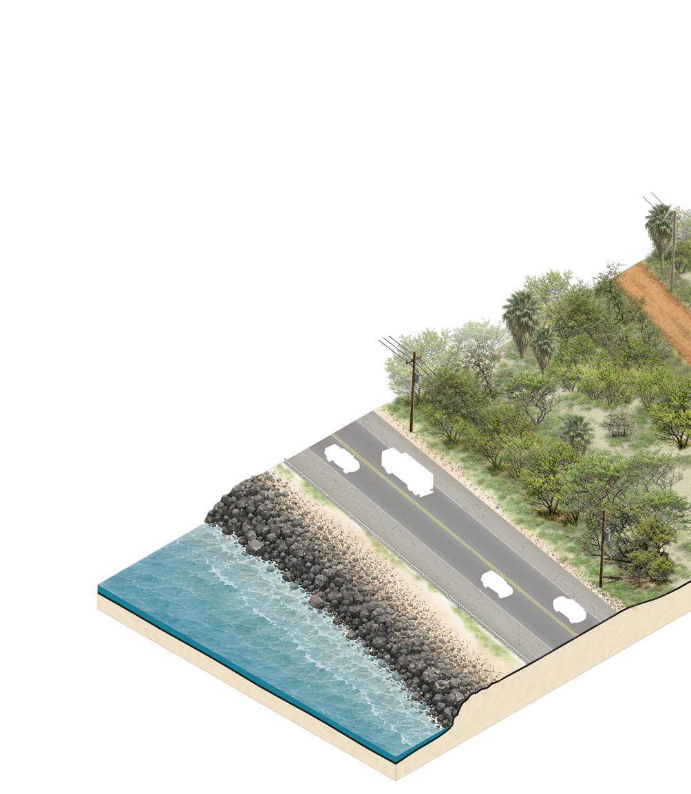
To further communicate the proof-of-concept design vision, a series of isometric transects is provided to help transition the viewer’s understanding from two-dimensional plan drawings to three-dimensional representations of the proposed design. The following pages illustrate these transects, highlighting the conceptual design strategies alongside existing site features and conditions.
When using the term “transect,” this report refers to isometric cross-sectional design drawings. These types of illustrative graphics allow for the effective representation of complex spatial configurations and land-water transitions, such as water levels relative to surrounding built structures and/ or ground conditions.
List of Transects:
Existing Transect (2026)
Near-Term Transect (Approximately 2045)
Long-Term Transect (Approximately 2075)
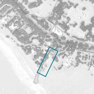
Transect Location
Catalytic Site 1 transect boundary (UHCDC)
Overview
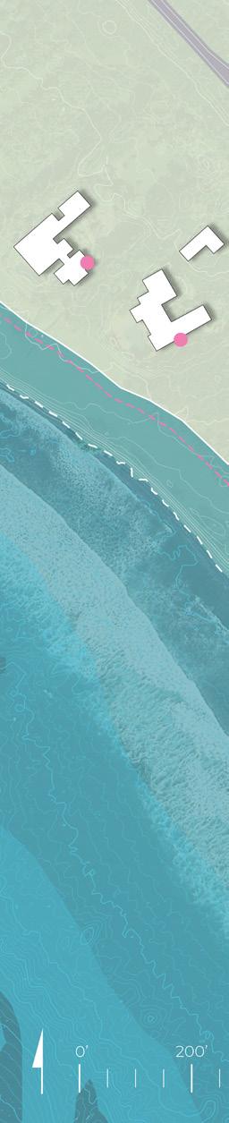
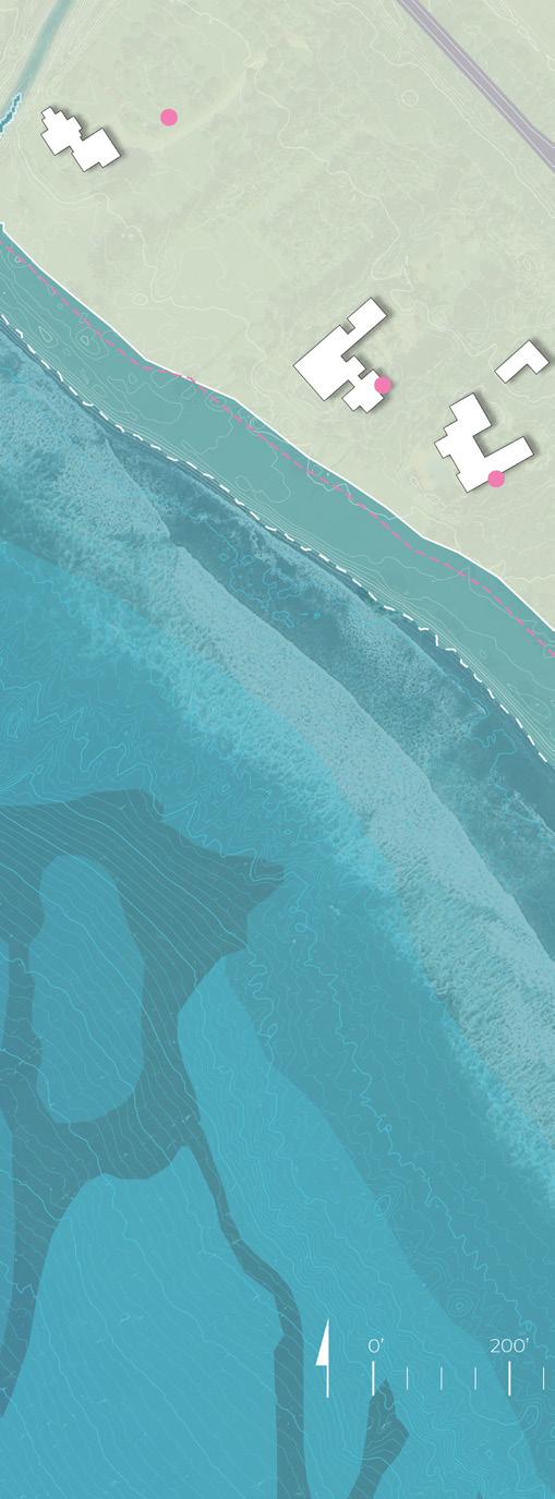
Each transect is defined by a 200-ft by 600-ft study area, allowing the illustrations to focus on site features and conditions most relevant to the proof-of-concept design vision.
Throughout this report, the term “transect” refers to wide, isometric cross-sectional drawings that effectively communicate complex spatial relationships, including changes in topography, water levels, built infrastructure, and surrounding ground conditions.
The transect location selected for Catalytic Site 1 highlights key components of the proof-of-concept design. In many cases, such transect drawings illustrate edge conditions and transitional
zones between land and water or between adjacent program elements, while demonstrating design strategies that are representative of other areas throughout the overall project area.
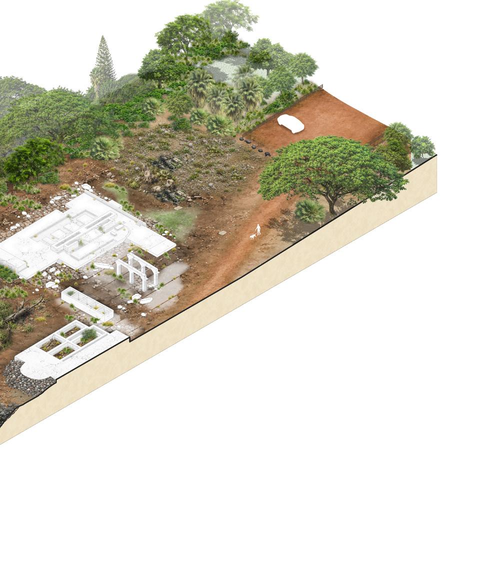
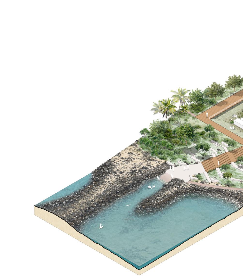
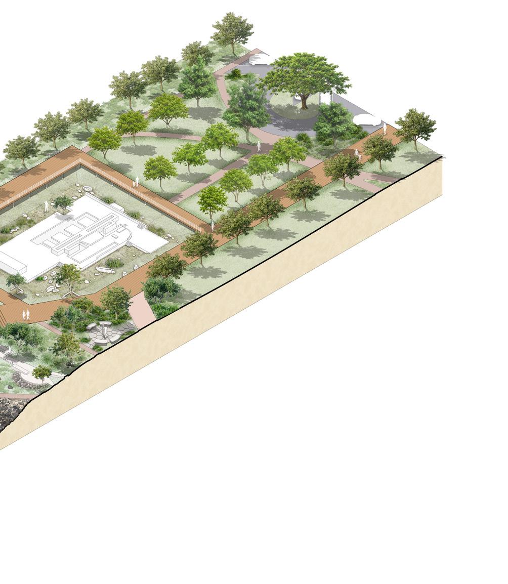
The Catalytic Site 1 transect is located near Olowalu Landing to illustrate existing site conditions—historic remnants, invasive species overgrowth, limited shoreline access, etc.—and to demonstrate how these features could be transformed through the implementation of the proposed resilient proof-of-concept design.
The transect study boundary, shown above in the context of existing site conditions, remains consistent across all three design time frames:
Catalytic Site Limit of Work
Existing (2026), Near-Term (approximately 2045), and Long-Term (approximately 2075). As discussed in Chapter 5, the project’s overarching time scale for these proof-of-concept designs is guided by the anticipated Honoapiʻilani Highway relocation schedule and sea level rise projections from NOAA’s 2022 Intermediate High sea level rise scenario for Hawaiʻi.
Locator diagrams in the bottom right corner of the drawings highlight how the transects are situated within their respective catalytic site limit of work plan view.
Transects Time Frame
Existing: 2026
Near-Term: Approximately 2045 (1.1’ SLR-XA)
Long-Term: Approximately 2075 (3.2’ SLR-XA)
TRANSECTS
EXISTING CONDITIONS
Olowalu Town - 2026
EXISTING VEGETATION
OLOWALU LANDING
SUGAR MILL REMNANTS
WATER ACCESS
TRANSECTS
NEAR-TERM VISION
Approximately 2045
SHADE TREES
PUBLIC SHORELINE PATH
VEGETATED BUFFER AND LIVING SHORELINE
OLOWALU LANDING
WATER ACCESS
SEAT AND RETAINING WALLS
CATALYTIC SITE 1 PROOF-OF-CONCEPT
PUBLIC PARK AMENITIES
SUGAR MILL REMNANT REMEDIATION AND ADAPTIVE REUSE
TRANSECTS
LONG-TERM VISION
Approximately 2075
PUBLIC SHORELINE PATH
VEGETATED BUFFER AND LIVING SHORELINE
OLOWALU LANDING
PIER AND BOARDWALK
SHADE TREES
SEAT AND RETAINING WALLS
PUBLIC PARK AMENITIES
MULTIPURPOSE COMMUNITY PAVILION WITH INTEGRATED COMFORT STATION WATER ACCESS
SHOWER
Olowalu Landing (UHCDC, 2024)
Perspectives
Building upon the previous, illustrative isometric transect drawings, the following section perspective studies and long-term eye-level rendering provide a sense of the user experience in the existing condition that contrasts with the near-term and long-term design proposals for Catalytic Site 1.
This illustrative representation format might assist report readers in visualizing the proposed changes and improvements over time more easily than abstract plan drawings.
Section perspective studies and eye-level renderings provide a sense of the experience in the existing conditions that contrasts with the nearterm and long-term design proposals within the Catalytic Site 1 limit of work. This illustrative representation format assists readers in visualizing the proposed changes and improvements over time more easily than plan and section drawings alone.
Consistent with the chronological organization established earlier in this chapter, the section perspectives are presented across three design time frames: Existing (2026), Near-Term (approximately 2045), and Long-Term (approximately 2075). As discussed in Chapter 5, these
Section Perspective Cut Location
proof-of-concept design horizons are guided by the anticipated relocation of Honoapiʻilani Highway and sea level rise projections based on NOAA’s 2022 Intermediate High sea level rise scenario for Hawaiʻi.
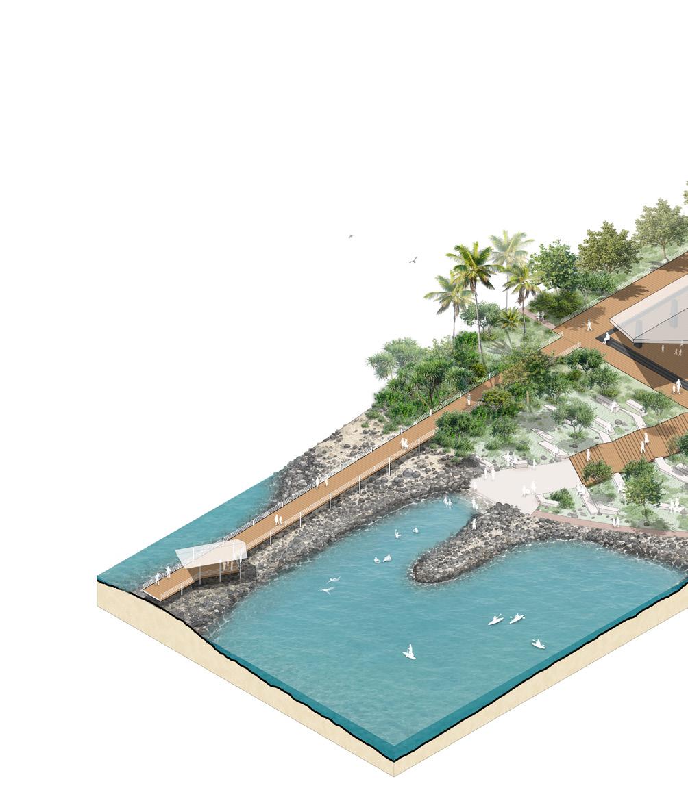
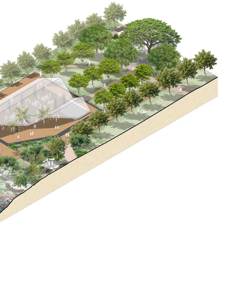
Following the sequence of section perspectives, an eye-level rendering illustrates a representative moment in time, depicting how Catalytic Site 1 could appear following implementation of the speculative long-term proof-of-concept design.
Both the section perspective and eye-level rendering locations were selected to highlight views that best represent the project’s design
Catalytic Site 1 section perspective and eye-level rendering locations (UHCDC)
intent and proposed key transformations. The descriptions that follow identify the primary design features and site characteristics illustrated in the existing, near-term, and long-term section perspectives.
Existing Section Perspective
Below is a list of existing site features that are seen in the section-perspective view of Catalytic Site 1:
• Overgrowth of vegetation including invasive species
• Feral cat colony that resides among historical remnants and vegetation
• Deteriorating Sugar Mill remnants with dangerous protruding elements (e.g., sharp rusting rebar, crumbling concrete, falling structures, etc.)
• Main point of water access for area due to private property prohibiting other beach access points
Near-Term Section Perspective
The list included below highlights proof-of-concept design features that are illustrated in the near-term section perspective:
• Clearing of invasive vegetation followed by native species planting
• Sugar Mill remnant remediation and adaptive reuse to ensure safe access to historical site
• Initial establishment of vegetated living shoreline buffer, with top of the wide, planted berm filled to 15-feet above existing sea level
• Implementation of public shoreline path to increase water access
• Seat and retaining walls added to stabilize slope and accomodate site users
Long-Term Section Perspective
Below is a list of proof-of-concept design elements that are shown in the long-term section perspective:
• Native vegetation supports native fauna and biodiversity
• Optional implementation of community pavilion with comfort station and public park amenities
• Elevated, living sea level rise protection system implemented with established native plantings
• Re-use of burried sugar mill remnant foundation to stabilize vegetated protective berm
• Addition of an Olowalu Pier for sea level rise-adapted user access and look-out spots; acts as community gathering space
Section Perspectives Time Frame
Existing: 2026
Near-Term: Approximately 2045 (1.1’ SLR-XA)
Long-Term: Approximately 2075 (3.2’ SLR-XA)
Eye-Level Rendering Time Frame
Long-Term: Approximately 2075 (3.2’ SLR-XA)
Section Perspective
EXISTING CONDITIONS
Olowalu Town - 2026
UNSAFE SUGAR MILL REMNANTS EXISTING SL
Section Perspective
NEAR-TERM VISION
Olowalu Town - Approximately 2045
PERSPECTIVES
Section Perspective
LONG-TERM VISION
Olowalu Town - Approximately 2075
VEGETATION AND HABITAT
PUBLIC SHORELINE PATH ON VEGETATED LIVING SHORELINE BUFFER
MULTIPURPOSE COMMUNITY PAVILION WITH PUBLIC PARK AMENITIES
3.2’ SLR
PERSPECTIVES
Eye-Level Rendering
LONG-TERM VISION
Olowalu Town - Approximately 2075
View of Improved Recreational Water Access and Pier at Olowalu Landing
Chapter 8 presents conceptual near-term and long-term visions for Catalytic Site 2, the coastal area around Mile Marker 14.
The speculative site-scale design interventions proposed for this location focus on balancing continued public waterfront and snorkeling access with climate adaptation and habitat restoration strategies.
Mile Marker 14 (UHCDC, 2025)
Background
This section of the report provides a high-level overview of several of the most significant features within Catalytic Site 2. Through multiple in-person site visits, along with engagement with stakeholders and members of the local community, the project team developed a comprehensive understanding of the site’s existing conditions and the significance of its various features within the broader project context.
While this overview does not encompass every feature, it highlights several of the site’s most prominent and frequently referenced elements. Additional details and discussion of each feature are provided on the following pages.
Listed Site Features:
Roadside Parking Waste and Management
Invasive Overgrowth
Beach Recreation and Snorkeling Olowalu Reef
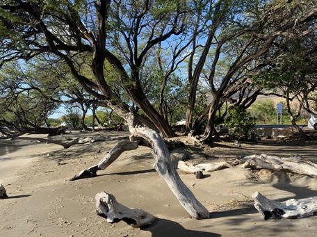
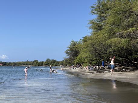
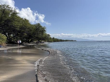
Located along Honoapiʻilani Highway south of Olowalu Town, the Mile Marker 14 shoreline is a well-known coastal stop that provides easy access to the famed Olowalu Reef. The site attracts both residents and visitors seeking clear water, sandy shoreline conditions, and convenient entry to one of West Maui’s most significant reef systems. Over time, the area has become a popular informal destination for snorkeling, swimming, and enjoying views of the Olowalu coastline.
Despite its popularity, the area has developed without the structure or amenities typically associated with a designated beach park. Access occurs informally from the roadside, and the
shoreline landscape reflects a mix of invasive coastal vegetation, open sand, and unmanaged areas. These conditions give the site a raw and undeveloped character, and present opportunities to improve shoreline management while preserving the natural qualities that draw people to the area.
Existing Site Features
The following categories provide an overview of key features found in the area surrounding Mile Marker 14. Understanding these existing conditions helps establish the site’s current character, opportunities, and constraints.
Overview
Beach at Mile Marker 14 (UHCDC, 2024)
Roadside Parking
Visitors accessing the beach at Mile Marker 14 typically park along an informal roadside pulloff located just off the highway shoulder. The area lacks defined circulation patterns, and vehicles park wherever space is available. Concrete traffic barriers separate the parking area from the beach, creating a narrow transition zone between parked vehicles and shoreline access. While this informal parking supports quick beach access, the absence of a defined layout can create congestion. The unimproved dirt conditions promote erosion and create sediment.
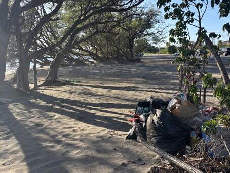
Waste and Management
Mile Marker 14 experiences consistent use as a snorkeling and beach access point, yet the site lacks formal waste management and maintenance. Trash bags and debris often accumulate on site, with no designated facilities or regular servicing provided. This condition reflects the challenges of managing a high-use recreational area without supporting infrastructure. Potentially formalizing the site’s beach park functions and improving maintenance present opportunities to improve stewardship and better support the level of use the area currently receives.
Invasive Overgrowth
Sections of the shoreline at Mile Marker 14 are heavily lined with invasive kiawe trees and dense vegetation. While these trees provide shade and a sense of enclosure along the beach edge, their spread can limit views of the shoreline and reduce space for circulation along the coast. The overgrowth also competes with native coastal vegetation and can contribute to an unmanaged landscape condition. Addressing invasive species in this area may present opportunities to restore native coastal plant communities while maintaining shaded areas for beach users.
Mile Marker 14 parking location (UHCDC, 2024)
Waste along Honoapiʻilani Highway and MM14 coastline (UHCDC, 2024)
Kiawe tree growth along MM14 beach coastline (UHCDC, 2024)
BACKGROUND
Beach Recreation and Snorkeling
The beach at Mile Marker 14 is known for its sandy shoreline and clear, shallow waters, making it a popular location for snorkeling and ocean recreation along the Olowalu coastline. The reef lies close to shore, allowing easy access to marine habitat and creating favorable conditions for beginner and experienced snorkelers. These nearshore reef conditions, combined with relatively calm waters, contribute to the site’s reputation as a convenient and desirable snorkeling destination.
The shoreline includes a mix of sand, rocky edges, and vegetative shading, creating a varied coastal setting that supports swimming, snorkeling, and informal gathering. The proximity of unimproved parking to the water facilitates easy access, though the site lacks basic amenities such as bathrooms or designated rinse stations for gear and post-use cleanup. With its scenic views and direct connection to Olowalu Reef, the site presents an opportunity to support ocean recreation while encouraging reef education and stewardship of the surrounding marine environment.
Olowalu Reef
Catalytic Site 2 provides immediate access to Olowalu Reef with its large diversity of coral and other important habitat. Minimizing erosion and sediment discharge into coastal waters in this area is vital to reef resilience.
In this location, a healthy reef is an important component of layered, nature-based living shoreline systems that protect the coast from the impacts of flooding and sea level rise.
Beach use at Mile Marker 14 (UHCDC, 2024)
Coast at Mile Marker 14 along Honoapiʻilani Highway (UHCDC, 2024)
Mushroom coral (TNC / Alana Yurkanin)
Olowalu reef located at Mile Marker 14 (TNC, 2024)
Kiawe grove at Mile Marker 14 (UHCDC, 2024)
Analysis
The following report pages feature a set of seven thematic site inventory and analysis maps, represented at the zoomed-in catalytic site scale, each covering a square area dimensioned 2,000-ft by 2,000-ft.
These maps spatially visualize select site conditions, program elements, and opportunities and constraints that have informed conceptual proof-of-concept design decisions for Catalytic Site 2.
List of Analysis Maps:
Existing Conditions (2026)
Wetland and Habitat
Hydrology and Topography
Land Ownership
Shoreline and Coastal Conditions
1.1’ Sea Level Rise Exposure Area (Approximately 2045)
3.2’ Sea Level Rise Exposure Area (Approximately 2075)
Catalytic Site 2 Proof-of-Concept Design
EXISTING CONDITIONS
Analysis map legend outlined below:
Honoapiʻilani Highway
Undesignated coastal parking
Existing streams
Stream outlet
reef
Existing coastline Heavily used beach
Mile Marker 14 beach goers in water (UHCDC, 2025)
Mile Marker 14 beach parking and vegetation (UHCDC, 2024)
ANALYSIS
Catalytic Site 2 Proof-of-Concept Design
WETLAND AND HABITAT
Analysis map legend outlined below:
Building footprints
Existing wetlands
Potential wetlands
Wetlands 100’ buffer
Wetland data adapted from Maui County Wetland Overlay Map (2024).
EXISTING WETLANDS
HONOAPIʻILANIHWY
OLOWALU REEF
UKUMEHAME
ANALYSIS
Catalytic Site 2 Proof-of-Concept Design
HYDROLOGY & TOPOGRAPHY
Analysis map legend outlined below:
5’ contour lines
1’ contour lines Ditches Gulches
Mauka view at Mile Marker 14 (UHCDC, 2025)
Mauka view at Mile Marker 14 (UHCDC, 2024)
OLOWALU REEF
ANALYSIS
Catalytic Site 2 Proof-of-Concept Design
LAND OWNERSHIP
Analysis map legend outlined below:
Building footprints
TMK parcel lines
Private landowner
State of Hawaiʻi
County of Maui
Olowalu: The Road to
Honoapiʻilani Highway at Mile Marker 14 (UHCDC, 2024)
Old cane haul road at Mile Marker 14 (UHCDC, 2025)
OLOWALU
HONOAPIʻILANIHWY
OLOWALU REEF
UKUMEHAME
ANALYSIS
Catalytic Site 2 Proof-of-Concept Design
SHORELINE & COASTAL CONDITIONS
Analysis map legend outlined below:
Building footprints
Sandy shoreline
Rocky shoreline
Sandy conditions
Vegetated conditions
Field conditions
Stream conditions
Cleared field conditions at Mile Marker 14 (UHCDC, 2025)
Vegetated coastline at Mile Marker 14 (UHCDC, 2024)
OLOWALU REEF
UKUMEHAME
Catalytic Site 2 Proof-of-Concept Design
1.1’ SEA LEVEL RISE EXPOSURE AREA
Analysis map legend outlined below:
Building footprints
On-site sewage disposal
Coastal erosion line
Existing coastline
1.1’ Sea level rise exposure area (approximately 2045)
Refined selected alternative
140’ Right of way
The Sea Level Rise Exposure Area (SLR-XA) maps the combined footprint of multiple coastal hazards anticipated as a result of sea level rise. SLR-XA modeling includes the following three chronic flooding hazards: passive flooding, annual high wave flooding, and coastal erosion.
For purposes of the Olowalu: The Road to Resilience project, based on NOAA’s current intermediate-high scenario, 1.1 feet of sea level rise are anticipated around 2045. (Also see Chapter 5 above.)
Data source: Pacific Islands Ocean Observing System (PacIOOS) sea level rise data (September, 2024)
HONOAPIʻILANIHWY
Catalytic Site 2 Proof-of-Concept Design
3.2’ SEA LEVEL RISE EXPOSURE AREA
Analysis map legend outlined below:
Building footprints
On-site sewage disposal
Coastal erosion line
Existing coastline
3.2’ Sea level rise exposure area (approximately 2075)
Refined selected alternative
140’ Right of way
The Sea Level Rise Exposure Area (SLR-XA) maps the combined footprint of multiple coastal hazards anticipated as a result of sea level rise. SLR-XA modeling includes the following three chronic flooding hazards: passive flooding, annual high wave flooding, and coastal erosion.
For purposes of the Olowalu: The Road to Resilience project, based on NOAA’s current intermediate-high scenario, 3.2 feet of sea level rise are anticipated around 2075. (Also see Chapter 5 above.)
Data source: Pacific Islands Ocean Observing System (PacIOOS) sea level rise data (September, 2024)
HONOAPIʻILANIHWY
Olowalu reef located at Mile Marker 14 (TNC, 2024)
Site Plans
Following the preceding site analysis, the proof-of-concept design documentation for Catalytic Site 2 begins with plan-view representations of the proposed concepts. Subsequent report pages illustrate a series of sequential design visions that were informed by the results of community and stakeholder engagement, site analysis, and interdisciplinary collaboration with technical experts.
List of Site Plans:
Existing Plan (2026)
Near-Term Plan (Approximately 2045)
Long-Term Plan (Approximately 2075)
Overview
The proposed conceptual design for Catalytic Site 2 is first presented through a series of planview drawings. Each catalytic site is defined by a 2,000-ft by 2,000-ft boundary, allowing the design to focus on the site features and conditions most relevant to the proof-of-concept vision.
The limit of work for Catalytic Site 2 encompasses a diverse range of existing features including archeological sites, roadside parking, waste dumping, invasive vegetation overgrowth, beach recreation and snorkeling, and the Olowalu reef.
The location and site extent were informed by analysis and community engagement to iden-
tify the areas most critical to address within the overall project area proof-of-concept design.
The boundary, shown above in the context of existing site conditions, remains consistent across all three design time frames: Existing (2026), Near-Term (approximately 2045), and LongTerm (approximately 2075). As discussed in Chapter 5, the project’s overarching time scale for these proof-of-concept designs is guided by the anticipated Honoapiʻilani Highway relocation schedule and sea level rise projections from NOAA’s 2022 Intermediate High sea level rise scenario for Hawaiʻi.
Catalytic Site Limit of Work
Plan view of Catalytic Site 2 limit of work (UHCDC)
Existing Plan
The first part of this chapter summarizes the current site conditions. Existing features establish the site’s physical character, while also highlighting several key challenges and opportunities that inform the proof-of-concept design.
Notable site conditions include a popular snorkeling destination, a nearby long-term houseless population, and evidence of illegal dumping along the roadway and coastline. Mile Marker 14 is also identified as an area experiencing significant coastal erosion, influenced by multiple factors including sediment accumulation and deteriorating roadway infrastructure. Collectively, these conditions—along with high levels of parking demand, tourism, and the prevalence of invasive species—degrade the health of the nearshore reef and shoreline. These existing challenges underscore the need to improve the site’s long-term resilience.
Near-Term Plan
The near-term proof-of-concept design for Catalytic Site 2 seeks to incorporate programs and uses related to the overall project goals.
Place and Community
• Multi-use path
• Potential conversion to public land
• Potential new public beach park
• Beach park parking
• Boardwalk access
Ecology and Habitat
• Reef restoration
• Mālama ʻāina (clean illegal dumping, etc.)
• Native dryland forest and stream restoration (erosion control)
• Wetland restoration
Climate and Hazards
• Sea level rise adaptation
• Partial roadway removal and nature-based adaptation solution with vegetated buffer
Long-Term Plan
The long-term proof-of-concept design of Catalytic Site 2 seeks to continue and strengthen the incorporation of programs related to the overall project goals.
Place and Community
• Multi-use path
• Boardwalk access to beach park
• Reef education
• Biocultural practices (loʻi kalo)
• Ahupuaʻa boundary marker
Ecology and Habitat
• Reef protection
• Maintain native dryland forest and streams (erosion control)
• Wetland expansion
• Vegetated buffer and living shoreline
Climate and Hazards
• SLR adaptation - beach park (adapt in place)
• SLR adaptation - roadway removal (retreat)
Site Plans Time Frame
Existing: 2026
Near-Term: Approximately 2045 (1.1’ SLR-XA)
Long-Term: Approximately 2075 (3.2’ SLR-XA)
UKUMEHAME
NEAR-TERM PLAN
Approximately 2045
Parking lot
Elevated shared-use boardwalk
Maintenance and emergency access pathway
Paved multipurpose area
Comfort station
Showers
Reef education hub
Small park pavilion
Lifeguard tower
Bridge / culvert
Vegetated buffer and living shoreline
Revetments
Riparian and stream restoration
Green
Wetland
LONG-TERM PLAN
2075
Parking lot
Elevated shared-use boardwalk
Elevated pedestrian only boardwalk
Maintenance and emergency access pathway
Paved multipurpose area
Comfort station
Showers
Reef education hub
Small park pavilion
Large park pavilion
Lifeguard tower
Shaded lookout structure
Bridge / culvert
Vegetated buffer and living shoreline
Revetments
Loʻi Hale loʻi ʻAuwai
Mile Marker 14 beach parking and vegetation (UHCDC, 2024)
Transects
To further communicate the proof-of-concept design vision, a series of isometric transects is provided to help transition the viewer’s understanding from two-dimensional plan drawings to three-dimensional representations of the proposed design. The following pages illustrate these transects, highlighting the conceptual design strategies alongside existing site features and conditions.
When using the term “transect,” this report refers to isometric cross-sectional design drawings. These types of illustrative graphics allow for the effective representation of complex spatial configurations and land-water transitions, such as water levels relative to surrounding built structures and/ or ground conditions.
List of Transects:
Existing Transect (2026)
Near-Term Transect (Approximately 2045)
Long-Term Transect (Approximately 2075)
Location
Overview
Each transect is defined by a 200-ft by 600-ft study area, allowing the illustrations to focus on site features and conditions most relevant to the proof-of-concept design vision.
Throughout this report, the term “transect” refers to wide, isometric cross-sectional drawings that effectively communicate complex spatial relationships, including changes in topography, water levels, built infrastructure, and surrounding ground conditions.
The transect location selected for Catalytic Site 2 highlights key components of the proof-of-concept design. In many cases, such transect drawings illustrate edge conditions and transitional
zones between land and water or between adjacent program elements, while demonstrating design strategies that are representative of other areas throughout the overall project area.
The Catalytic Site 2 transect is located near Mile Marker 14 to illustrate existing site conditions—a popular beach area, the Honoapiʻilani Highway, undesignated roadside parking, the old cane haul road, etc.—and to demonstrate how these features could be transformed through the implementation of the proposed resilient proof-ofconcept design.
The transect study boundary, shown above in the context of existing site conditions, remains
Catalytic Site 2 transect boundary (UHCDC)
Transect
Catalytic Site Limit of Work
consistent across all three design time frames: Existing (2026), Near-Term (approximately 2045), and Long-Term (approximately 2075). As discussed in Chapter 5, the project’s overarching time scale for these proof-of-concept designs is guided by the anticipated Honoapiʻilani Highway relocation schedule and sea level rise projections from NOAA’s 2022 Intermediate High sea level rise scenario for Hawaiʻi.
Locator diagrams in the bottom right corner of the drawings highlight how the transects are situated within their respective catalytic site limit of work plan view.
Transects Time Frame
Existing: 2026
Near-Term: Approximately 2045 (1.1’ SLR-XA)
Long-Term: Approximately 2075 (3.2’ SLR-XA)
EXISTING CONDITIONS
Mile Marker 14 - 2026
HONOAPIʻILANI HIGHWAY
INVASIVE SPECIES
OLOWALU
UNDESIGNATED PARKING
SEDIMENT AND EROSION CATALYTIC SITE 2 PROOF-OF-CONCEPT
SANDY BEACH
OLD CANE HAUL ROAD
TRANSECTS
NEAR-TERM VISION
Mile Marker 14 - Approximately 2045
REALIGNED HONOAPIʻILANI HIGHWAY
WETLAND AND NATIVE HABITAT RESTORATION
MAINTENANCE AND EMERGENCY ACCESS
PARK PAVILION
VEGETATED BUFFER AND LIVING SHORELINE
MULTI-USE PATH
BEACH PARK
TRANSECTS
LONG-TERM VISION
Mile Marker 14 - Approximately 2075
REALIGNED HONOAPIʻILANI HIGHWAY
WETLAND AND NATIVE HABITAT RESTORATION
MAINTENANCE AND EMERGENCY ACCESS
PARK PAVILION
BOARDWALK WITH SHADED LOOKOUT STRUCTURE CATALYTIC SITE 2
VEGETATED BUFFER AND LIVING SHORELINE
MULTI-USE PATH
BEACH PARK
Mile Marker 14 beach (UHCDC, 2024)
Perspectives
Building upon the previous, illustrative isometric transect drawings, the following section perspective studies and long-term eye-level rendering provide a sense of the user experience in the existing condition that contrasts with the near-term and long-term design proposals for Catalytic Site 2.
This illustrative representation format might assist report readers in visualizing the proposed changes and improvements over time more easily than abstract plan drawings.
Section perspective studies and eye-level renderings provide a sense of the experience in the existing conditions that contrasts with the nearterm and long-term design proposals within the Catalytic Site 2 limit of work. This illustrative representation format assists readers in visualizing the proposed changes and improvements over time more easily than plan and section drawings alone.
Consistent with the chronological organization established earlier in this chapter, the section perspectives are presented across three design time frames: Existing (2026), Near-Term (approximately 2045), and Long-Term (approximately 2075). As discussed in Chapter 5, these
proof-of-concept design horizons are guided by the anticipated relocation of Honoapiʻilani Highway and sea level rise projections based on NOAA’s 2022 Intermediate High sea level rise scenario for Hawaiʻi.
Following the sequence of section perspectives, an eye-level rendering illustrates a representative moment in time, depicting how Catalytic Site 2 could appear following implementation of the speculative long-term proof-of-concept design.
Both the section perspective and eye-level rendering locations were selected to highlight views that best represent the project’s design
Catalytic Site 2 section perspective and eye-level rendering locations (UHCDC)
intent and proposed key transformations. The descriptions that follow identify the primary design features and site characteristics illustrated in the existing, near-term, and long-term section perspectives.
Existing Section Perspective
Below is a list of existing site features that are seen in the section perspective view of Catalytic Site 2:
• Heavy beach use at Mile Marker 14 including snorkeling and water recreation
• Erosion and sedimentation
• Kiawe trees lining coastline along with other invasive species
• Undesignated beachside parking along Honoapiʻilani Highway
• Clearing of vegetation occuring on the mauka side of the highway
Near-Term Section Perspective
The list included below highlights proof-of-concept design features that are illustrated in the near-term section perspective:
• Wetland and/or native habitat restoration
• Creation of new climate-adapted beach park to provide shaded gathering spaces, weather protection, and picnic benches and tables
• Honoapiʻilani Highway decommissioning and removal
• Emergency and maintenance access in location of former highway right of way
• Wide landscaped berm, filled to 15-feet in elevation above existing sea level, designed to prevent uncontrolled flooding and sedimentation
• Living shoreline buffer vegetation might include:
» Shrubs and small trees: Naupaka Kahakai, ʻAkiʻaki, ʻUhaloa
» Large trees: Hala, Kamani, Milo, Niu
• Reef education to facilitate sustainable beach use and recreation, as well as reefsafe snorkeling
Long-Term Section Perspective
Below is a list of additional proof-of-concept design elements that are shown in the long-term section perspective:
• Mauka-makai hydrological connection
• Climate-adaptive coral reef restoration
• Multimodal connectivity via elevated boardwalks over restored wetland and native habitat
• Vegetated living shoreline buffer increases biodiversity and continues mitigating erosion and flooding caused by sea level rise and storm surge
Section Perspectives Time Frame
Existing: 2026
Near-Term: Approximately 2045 (1.1’ SLR-XA)
Long-Term: Approximately 2075 (3.2’ SLR-XA)
Eye-Level Rendering Time Frame
Long-Term: Approximately 2075 (3.2’ SLR-XA)
Section Perspective
EXISTING CONDITIONS
Mile Marker 14 - 2026 SNORKELING AND RECREATIONAL BEACH USE
UNIMPROVED PARKING ALONG EXISTING HONOAPIʻILANI HIGHWAY EXISTING SL
EROSION AND SEDIMENT
PERSPECTIVES
Section Perspective
NEAR-TERM VISION
Mile Marker 14 - Approximately 2045
REEF EDUCATION AND SNORKELING
BEACH PARK WITH SHOWERS AND PAVILIONS
VEGETATED LIVING SHORELINE BUFFER AND MAINTENANCE ACCESS
WETLAND OR NATIVE HABITAT RESTORATION
PERSPECTIVES
Section Perspective
LONG-TERM VISION
Mile Marker 14 - Approximately 2075
REEF EDUCATION AND SNORKELING
BEACH PARK WITH SHOWERS AND PAVILIONS
VEGETATED LIVING SHORELINE BUFFER AND MAINTENANCE ACCESS
BOARDWALK OVER RESTORED WETLAND AND NATIVE HABITAT
3.2’ SLR
PERSPECTIVES
Eye-Level Rendering
LONG-TERM VISION
Mile Marker 14 - Approximately 2075
View of Future Sustainable Beach Park Amenities and Living Shoreline
Chapter 9 illustrates conceptual near-term and long-term visions for Catalytic Site 3, the area around the existing Ukumehame Beach Park and adjacent wetlands.
Of the project’s three catalytic sites, this location’s proposed speculative site-scale design interventions are most heavily focused on native ecosystem restoration and climate adaptation, while maintaining public access to the coastal area and its iconic surf spot.
Ukumehame Beach Park (UHCDC, 2024)
Background
This section of the report provides a high-level overview of several of the most significant features within Catalytic Site 3. Through multiple in-person site visits, along with engagement with stakeholders and members of the local community, the project team developed a comprehensive understanding of the site’s existing conditions and the significance of its various features within the broader project context.
While this overview does not encompass every feature, it highlights several of the site’s most prominent and frequently referenced elements. Additional details and discussion of each feature are provided on the following pages.
Listed Site Features:
Sediment Basin
Salt-Crusted Ground
Asphalt Parking Lot
Seawall and Coastal Edge
Beach Park Infrastructure
Ukumehame (UHCDC, 2024)
Overview
Ukumehame Beach Park is located on the makai side of Honoapiʻilani Highway, near Mile Marker 12. The site includes shoreline access and a paved parking area. Compared to other nearby coastal destinations, it receives relatively low levels of recreational use. Visitors often stop briefly to rest or take in the views. The area is also known locally for its nearshore reef surf conditions, popular with beginners and longboarders.
Catalytic Site 3 is a broad, low-lying coastal area characterized by shoreline erosion, sediment movement, and hardened infrastructure built to protect Honoapiʻilani Highway. These conditions contribute to an ex-
posed and evolving landscape where coastal processes are clearly visible across the site. As shoreline conditions continue to evolve, the site presents an opportunity to transition from a traditional beach park into a wetland and habitat restoration area that supports coastal resilience, sea level rise adaptation, while maintaining public access.
Existing Site Features
The following categories provide an overview of existing features found within and surrounding Ukumehame Beach Park. Understanding these conditions helps establish the site’s current character, opportunities, and constraints.
Sediment Basin
Immediately south of Catalytic Site 3, is a sediment basin, located mauka of Honoapiʻilani Highway, characterized by dry, rocky conditions, red soil, and sparse vegetation. The basin functions as a catchment area for runoff and sediment moving downslope toward the coast, helping to manage water flow within the broader watershed. The surrounding landscape is largely barren, with exposed soils and minimal ground cover, reflecting the harsh and arid conditions of the area. Its proximity to the highway and coastal zone highlights the relationship between upland drainage, sediment transport, and shoreline conditions.
Salt-Crusted Ground
Mauka of the highway, areas of salt-crusted ground are present throughout the site, indicating the interaction between ocean water, evaporation, and soil. These conditions suggest that seawater regularly infiltrates or reaches near the surface, particularly in low-lying areas behind the shoreline. The ground is largely flat and sparsely vegetated, with patches of hardy coastal species adapted to saline and arid conditions. This environment reflects the site’s exposure to coastal processes and highlights its potential to support wetland or brackish habitat systems.
Asphalt Parking Lot
A paved parking lot provides primary access to Ukumehame Beach Park, though its condition is worn and largely unmaintained. The asphalt surface lacks defined striping or organization, and portions of the lot show signs of deterioration. Along the makai edge, the pavement is gradually eroding into the adjacent sand, reflecting ongoing coastal processes and exposure to wave action. Minimal amenities are provided, with only a temporary restroom present, contributing to the site’s limited use and overall underdeveloped condition.
Ukumehame sediment basin (UHCDC, 2024)
Ukumehame Beach Park parking lot (UHCDC, 2024)
Salt-crusted ground (UHCDC, 2024)
BACKGROUND
Seawall and Coastal Edge
A seawall has been constructed along the shoreline south of Ukumehame Beach Park to protect Honoapiʻilani Highway from coastal erosion. The highway sits elevated on a berm directly mauka of the park, placing critical infrastructure in close proximity to an actively changing shoreline. While the seawall has helped stabilize sections of the coast, it has also altered natural coastal processes, influencing wave energy, sediment movement, and shoreline conditions over time.
These changes are evident in the accumulation of debris along the beach and documented occurrences of sediment plumes in nearshore waters. The shoreline reflects a dynamic and evolving edge shaped by both natural forces and engineered interventions. This condition highlights an opportunity to rethink how the coastal edge functions while continuing to protect the adjacent highway.
Beach Park Infrastructure
Maui County’s recent Beach Parks Vulnerability and Adaptation Study, which assessed the vulnerability of existing parks to coastal hazards and sea level rise, identified Ukumehame Beach Park as a site with low adaptation potential and limited future viability.
In addition to the parking lot and portable toilet mentioned above, the park currently offers limited rustic amenities—mainly picnic tables and barbecue grills—all of which are exposed to full sun and show signs of erosion, as well as a general lack of maintenance.
Sea wall along Honoapiʻilani Highway (UHCDC, 2024)
Ukumehame coast along Honoapiʻilani Highway (UHCDC, 2024)
Ukumehame Beach Park picnic tables (UHCDC, 2024)
Hardened shoreline along Honoapiʻilani Highway near Ukumehame Beach Park (TNC, 2024)
Vegetation at Ukumehame Beach Park (UHCDC, 2025)
Analysis
The following report pages feature a set of seven thematic site inventory and analysis maps, represented at the zoomed-in catalytic site scale, each covering a square area dimensioned 2,000-ft by 2,000-ft.
These maps spatially visualize select site conditions, program elements, and opportunities and constraints that have informed conceptual proof-of-concept design decisions for Catalytic Site 3.
List of Analysis Maps:
Existing Conditions (2026)
Wetland and Habitat
Hydrology and Topography
Land Ownership
Shoreline and Coastal Conditions
1.1’ Sea Level Rise Exposure Area (Approximately 2045)
3.2’ Sea Level Rise Exposure Area (Approximately 2075)
EXISTING CONDITIONS
Analysis map legend outlined below:
Honoapiʻilani Highway
Parking lot
Existing gulches and ditches
Hydrological connection
Wetlands
Existing coastline
Ukumehame Beach Park
Popular surf break access point
Ukumehame Beach Park parking lot (UHCDC, 2024)
Ukumehame Beach Park picnic tables (UHCDC, 2024)
Catalytic Site 3 Proof-of-Concept Design
WETLAND AND HABITAT
Analysis map legend outlined below:
Building footprints
Existing wetlands
Potential wetlands
Wetlands 100’ buffer
Wetland data adapted from Maui County Wetland Overlay Map (2024).
Existing wetlands at Ukumehame Beach Park (UHCDC, 2024)
Salt-crusted wetlands in Ukumehame (UHCDC, 2024)
HONOAPIʻILANI HIGHWAY
Catalytic Site 3 Proof-of-Concept Design
HYDROLOGY & TOPOGRAPHY
Analysis map legend outlined below:
5’ contour lines
1’ contour lines Ditches Gulches
Ukumehame sediment basin (UHCDC, 2024)
Ukumehame Stream (UHCDC, 2024)
HANAULAGULCH
HONOAPIʻILANI HIGHWAY
MAKIWA GULCH
ANALYSIS
Catalytic Site 3 Proof-of-Concept Design
LAND OWNERSHIP
Analysis map legend outlined below:
Building footprints
TMK parcel lines
Private landowner
State of Hawaiʻi
County of Maui
WETLANDS
Road view from Ukumehame Beach Park (UHCDC, 2025)
Dirt road near Ukumehame Beach Park (UHCDC, 2024)
HONOAPIʻILANI HIGHWAY
Catalytic Site 3 Proof-of-Concept Design
SHORELINE & COASTAL CONDITIONS
Analysis map legend outlined below:
Building footprints
Sandy shoreline
Hardened shoreline
Sandy conditions
Vegetated conditions
Hardened conditions
Wetland conditions
Rocky shoreline at Ukumehame (UHCDC, 2024)
Shoreline at Ukumehame Beach Park (UHCDC, 2025)
HONOAPIʻILANI HIGHWAY
1.1’ SEA LEVEL RISE EXPOSURE AREA
Analysis map legend outlined below:
Building footprints
On-site sewage disposal
Coastal erosion line
Existing coastline
1.1’ Sea level rise exposure area (approximately 2045)
Refined selected alternative
Refined selected alternative (viaduct)
140’ Right of way
The Sea Level Rise Exposure Area (SLR-XA) maps the combined footprint of multiple coastal hazards anticipated as a result of sea level rise. SLR-XA modeling includes the following three chronic flooding hazards: passive flooding, annual high wave flooding, and coastal erosion.
For purposes of the Olowalu: The Road to Resilience project, based on NOAA’s current intermediate-high scenario, 1.1 feet of sea level rise are anticipated around 2045. (Also see Chapter 5 above.)
Data source: Pacific Islands Ocean Observing System (PacIOOS) sea level rise data (September, 2024)
HONOAPIʻILANI HIGHWAY
3.2’ SEA LEVEL RISE EXPOSURE AREA
Analysis map legend outlined below:
Building footprints
On-site sewage disposal
Coastal erosion line
Existing coastline
3.2’ Sea level rise exposure area (approximately 2075)
Refined selected alternative
Refined selected alternative (viaduct)
140’ Right of way
The Sea Level Rise Exposure Area (SLR-XA) maps the combined footprint of multiple coastal hazards anticipated as a result of sea level rise. SLR-XA modeling includes the following three chronic flooding hazards: passive flooding, annual high wave flooding, and coastal erosion.
For purposes of the Olowalu: The Road to Resilience project, based on NOAA’s current intermediate-high scenario, 3.2 feet of sea level rise are anticipated around 2075. (Also see Chapter 5 above.)
Data source: Pacific Islands Ocean Observing System (PacIOOS) sea level rise data (September, 2024)
HONOAPIʻILANI HIGHWAY
Hardened shoreline along Honoapiʻilani Highway near Ukumehame Beach Park (TNC, 2024)
Site Plans
Following the preceding site analysis, the proof-of-concept design documentation for Catalytic Site 3 begins with plan-view representations of the proposed concepts. Subsequent report pages illustrate a series of sequential design visions that were informed by the results of community and stakeholder engagement, site analysis, and interdisciplinary collaboration with technical experts.
List of Site Plans:
Existing Plan (2026)
Near-Term Plan (Approximately 2045)
Long-Term Plan (Approximately 2075)
Overview
The proposed conceptual design for Catalytic Site 3 is first presented through a series of planview drawings. Each catalytic site is defined by a 2,000-ft by 2,000-ft boundary, allowing the design to focus on the site features and conditions most relevant to the proof-of-concept vision.
Catalytic Site 3 encompasses a diverse range of existing features including salt-crusted ground located in designated wetland areas, an asphalt parking lot along with limited beach park infrastructure, a seawall, and a partially hardened coastal edge.
The location was informed by site analysis and community engagement which identified the
areas most critical to address within the overall project vision.
The site boundary, shown above in the context of existing conditions, remains consistent across all three design time frames: Existing (2026), Near-Term (approximately 2045), and Long-Term (approximately 2075). As discussed in Chapter 5, the project’s overarching time scale for these proof-of-concept designs is guided by the anticipated Honoapiʻilani Highway relocation schedule and sea level rise projections from NOAA’s 2022 Intermediate High sea level rise scenario for Hawaiʻi.
Plan view of Catalytic Site 3 limit of work (UHCDC)
Catalytic Site Limit of Work
Existing Plan
The first part of this chapter summarizes the current site conditions. Existing features establish the site’s physical character while also highlighting several key challenges and opportunities that inform the proof-of-concept design.
Notable site conditions include a hardened, rocky shoreline with existing seawall, and a popular surf break located at Ukumehame Beach Park, which was identified by a Maui County study as having low potential for sea level rise adaptation. Existing coastal erosion, disturbed wetland areas, and sedimentation hotspots within the site are influenced by several factors, including roadway erosion, deteriorating beach park infrastructure, invasive species, and nearby sources of pollution, such as the firing range and Honoapiʻilani Highway. Together, these conditions contribute to ongoing shoreline degradation and highlight the need for strategies that enhance the site’s long-term resilience.
Near-Term Plan
The near-term proof-of-concept design for Catalytic Site 3 seeks to incorporate programs and uses related to the overall project goals.
• SLR adaptation (consider seawall, highway and parking options or retreat)
• Address potential pollutants
Long-Term Plan
The long-term proof-of-concept design of Catalytic Site 3 seeks to continue and strengthen the incorporation of programs related to the overall project goals.
Place and Community
• Expand access via network of boardwalks
• Mauka hiking access
• Wetland education
• Wildlife watching
• Surfing
• Paʻakai (salt) farming and other biocultural practices
• Consider land return
Ecology and Habitat
• Native habitat restoration and sediment mitigation
• Wetland expansion
• Vegetated buffer and living shoreline
• Reef protection
Climate and Hazards
• SLR adaptation (protection, retreat, and nature-based solutions)
Site Plans Time Frame
Existing: 2026
Near-Term: Approximately 2045 (1.1’ SLR-XA)
Long-Term: Approximately 2075 (3.2’ SLR-XA)
MAKIWA GULCH
SITE PLANS
Catalytic Site 3 Proof-of-Concept Design
NEAR-TERM PLAN
Approximately 2045
Elevated shared-use drivable boardwalk
Elevated water access boardwalk
Elevated multi-use path boardwalk (West Maui Greenway)
Maintenance and emergency access pathway
Access ramp
Paved multipurpose area
Comfort station
Shower
Wetland education hub
Small shaded lookout structure
Large shaded lookout structure
Bridge / culvert and hydrological connection
Seawall removal and repurpose
Revetments
Steps leading to sandy area
Vegetated buffer and living shoreline
Phytoremediation and site preparation
Riparian and stream restoration
Green stormwater infrastructure
Wetland restoration and expansion
Educational signage
Wetland education hub amenities
MAKIWA GULCH
Parking lot
Elevated shared-use drivable boardwalk
Elevated pedestrian only boardwalk
Elevated water access boardwalk
Elevated multi-use path boardwalk (West Maui Greenway)
Maintenance and emergency access pathway
Salt collection ramp
Paved multipurpose area
Comfort station
Shower
Wetland education hub
Small shaded lookout structure
Large shaded lookout structure
Bridge / culvert and hydrological connection
Seawall removal and repurpose
Revetments
Steps leading to sandy area
Vegetated buffer and living shoreline
Paʻakai (salt) collection and farming
Riparian and stream restoration
Green stormwater infrastructure
Wetland restoration and expansion and native habitat protection
WETLANDS
MAKIWA GULCH
Hardened shoreline at Ukumehame Beach Park (UHCDC, 2025)
Transects
To further communicate the proof-of-concept design vision, a series of isometric transects is provided to help transition the viewer’s understanding from two-dimensional plan drawings to three-dimensional representations of the proposed design. The following pages illustrate these transects, highlighting the conceptual design strategies alongside existing site features and conditions.
When using the term “transect,” this report refers to isometric cross-sectional design drawings. These types of illustrative graphics allow for the effective representation of complex spatial configurations and land-water transitions, such as water levels relative to surrounding built structures and/ or ground conditions.
List of Transects:
Existing Transect (2026)
Near-Term Transect (Approximately 2045)
Long-Term Transect (Approximately 2075)
Transect Location
Overview
Each transect is defined by a 200-ft by 600-ft study area, allowing the illustrations to focus on site features and conditions most relevant to the proof-of-concept design vision.
Throughout this report, the term “transect” refers to wide, isometric cross-sectional drawings that effectively communicate complex spatial relationships, including changes in topography, water levels, built infrastructure, and surrounding ground conditions.
The transect location selected for Catalytic Site 3 highlights key components of the proof-of-concept design. In many cases, such transect drawings illustrate edge conditions and transitional
zones between land and water or between adjacent program elements, while demonstrating design strategies that are representative of other areas throughout the overall project area.
The Catalytic Site 3 transect is located near Ukumehame Beach Park to illustrate existing site conditions—a sea wall, the Honoapiʻilani Highway, the old cane haul road, invasive vegetation, etc.—and to demonstrate how these features could be transformed through the implementation of the proposed resilient proof-ofconcept design.
The transect study boundary, shown above in the context of existing site conditions, remains
Catalytic Site 3 transect boundary (UHCDC)
Catalytic Site Limit of Work
consistent across all three design time frames: Existing (2026), Near-Term (approximately 2045), and Long-Term (approximately 2075). As discussed in Chapter 5, the project’s overarching time scale for these proof-of-concept designs is guided by the anticipated Honoapiʻilani Highway relocation schedule and sea level rise projections from NOAA’s 2022 Intermediate High sea level rise scenario for Hawaiʻi.
Locator diagrams in the bottom right corner of the drawings highlight how the transects are situated within their respective catalytic site limit of work plan view.
Transects Time Frame
Existing: 2026
Near-Term: Approximately 2045 (1.1’ SLR-XA)
Long-Term: Approximately 2075 (3.2’ SLR-XA)
TRANSECTS
EXISTING CONDITIONS
Ukumehame Wetlands - 2026
INVASIVE SPECIES
HONOAPIʻILANI HIGHWAY
SEDIMENT AND EROSION
SEAWALL (HARDENED SHORELINE)
CATALYTIC SITE 3 PROOF-OF-CONCEPT
POTENTIAL WETLANDS
OLD CANE HAUL ROAD
TRANSECTS
NEAR-TERM VISION
Ukumehame Wetlands - Approximately 2045
SURF ACCESS NATIVE
MAINTENANCE AND EMERGENCY ACCESS
WETLAND RESTORATION AND EXPANSION
HABITAT
ELEVATED SHARED-USE DRIVABLE BOARDWALK
VEGETATED BUFFER AND LIVING SHORELINE
PHYTOREMEDIATION AND SITE PREPARATION
ELEVATED MULTI-USE PATH (WEST MAUI GREENWAY)
LONG-TERM VISION
Ukumehame Wetlands - Approximately 2075
MAINTENANCE AND EMERGENCY ACCESS
WETLAND RESTORATION AND EXPANSION
SURF ACCESS NATIVE HABITAT
ELEVATED SHARED-USE DRIVABLE BOARDWALK
SALT COLLECTION AREA
PAʻAKAI
ELEVATED MULTI-USE PATH
(WEST MAUI GREENWAY)
BUFFER AND LIVING SHORELINE
Salt-crusted wetlands in Ukumehame (UHCDC, 2024)
Perspectives
Building upon the previous, illustrative isometric transect drawings, the following section perspective studies and long-term eye-level rendering provide a sense of the user experience in the existing condition that contrasts with the near-term and long-term design proposals for Catalytic Site 3.
This illustrative representation format might assist report readers in visualizing the proposed changes and improvements over time more easily than abstract plan drawings.
Section perspective studies and eye-level renderings provide a sense of the experience in the existing conditions that contrasts with the nearterm and long-term design proposals within the Catalytic Site 3 limit of work. This illustrative representation format assists readers in visualizing the proposed changes and improvements over time more easily than plan and section drawings alone.
Consistent with the chronological organization established earlier in this chapter, the section perspectives are presented across three design time frames: Existing (2026), Near-Term (approximately 2045), and Long-Term (approximately 2075). As discussed in Chapter 5, these
proof-of-concept design horizons are guided by the anticipated relocation of Honoapiʻilani Highway and sea level rise projections based on NOAA’s 2022 Intermediate High sea level rise scenario for Hawaiʻi.
Following the sequence of section perspectives, an eye-level rendering illustrates a representative moment in time, depicting how Catalytic Site 3 could appear following implementation of the speculative long-term proof-of-concept design.
Both the section perspective and eye-level rendering locations were selected to highlight views that best represent the project’s design
Catalytic Site 3 section perspective and eye-level rendering locations (UHCDC)
intent and proposed key transformations. The descriptions that follow identify the primary design features and site characteristics illustrated in the existing, near-term, and long-term section perspectives.
Existing Section Perspective
Below is a list of existing site features that are seen in the section perspective view of Catalytic Site 3:
• Seawall and hardened shoreline along Honoapiʻilani Highway
• Sediment and erosion
• Former cane haul road currently used for access
• Seasonal wetlands and salt-crusted soil
• A variety of invasive species along the highway and mauka of the old cane haul road
Near-Term Section Perspective
The list included below highlights proof-of-concept design features that are illustrated in the near-term section perspective:
• Seawall and highway removal with re-use of clean materials on site
• Implementation of vegetated living shoreline buffer using native plantings to help with flood and erosion control
• Wetland and native habitat restoration
» Vegetated flats
» Hydrological connection (mauka-makai)
» Seasonal mud and salt flats
• Wide multi-use boardwalk in location of former cane haul road (West Maui Greenway), designed to be elevated to a height of 15 feet above existing sea level
• Wetland education hub, elevated and accessed via boardwalks
• Phytoremediation and site preparation for biocultural restoration
Long-Term Section Perspective
Below is a list of additional proof-of-concept design elements that are shown in the long-term section perspective:
• Dune enhancement and continued living shoreline management
• Wetlands and native habitat expansion and maintenance
» Seasonal mud and salt flats
» Vegetated flats among open waterbodies
• Paʻakai collection area (biocultural restoration)
Section Perspectives Time Frame
Existing: 2026
Near-Term: Approximately 2045 (1.1’ SLR-XA)
Long-Term: Approximately 2075 (3.2’ SLR-XA)
Eye-Level Rendering Time Frame
Long-Term: Approximately 2075 (3.2’ SLR-XA)
PERSPECTIVES
Section Perspective
EXISTING CONDITIONS
Ukumehame Wetlands - 2026
SEAWALL ALONG EXISTING HONOAPIʻILANI HIGHWAY
SEDIMENT AND EROSION
EXISTING SL
FORMER CANE HAUL ROAD
INVASIVE SPECIES AND SEASONAL WETLANDS
PERSPECTIVES
Section Perspective
NEAR-TERM VISION
Ukumehame Wetlands - Approximately 2045
VEGETATED LIVING SHORELINE BUFFER
WETLAND AND NATIVE HABITAT RESTORATION
MULTI-USE BOARDWALK (WEST MAUI GREENWAY) WITH WETLAND EDUCATION HUB
PHYTOREMEDIATION AND SITE PREPARATION FOR BIOCULTURAL RESTORATION
PERSPECTIVES
Section Perspective
LONG-TERM VISION
Ukumehame Wetlands - Approximately 2075
VEGETATED LIVING SHORELINE BUFFER AND NATIVE HABITAT
RESTORED WETLANDS AND SEASONAL MUD FLATS
MULTI-USE BOARDWALK (WEST MAUI GREENWAY) WITH WETLAND EDUCATION HUB
SALT COLLECTION AREA (PAʻAKAI)
PERSPECTIVES
Eye-Level Rendering
LONG-TERM VISION
Ukumehame Wetlands - Approximately 2075
View of Multi-Use Boardwalk above Restored Wetlands, Native Habitat, and Salt Collection Area
COST ESTIMATE 10 09 08
Based on the proposed long-term conceptual design visions presented in Chapters 6 through 9 above, Chapter 10 provides a conceptual rough order of magnitude cost estimate, intended to inform and support future planning, funding discussions, decision making, and scope determination for the project area.
Site 3 Eye-Level Rendering (UHCDC, 2026)
Catalytic
Rough Order of Magnitude (ROM) Cost Summary
The following rough order of magnitude cost estimate report was prepared by J. Uno & Associates, Inc. in June 2026. It is based on the conceptual proof-of-concept design materials included above and provides a planning-level cost framework for Olowalu: The Road to Resilience.
It is important to note that conceptual ROM cost was only determined for the project’s long-term visions, summarized in Chapters 6 through 9 above .
At the appropriate locations, interspersed throughout the cost estimator’s conceptual ROM report and project cost summary pages, readers will find plan view drawings, prepared by UHCDC and rendered in color, illustrating the location and spatial extent of four cost summary segments at the overall project scale, as well as limit of work outlines for Catalytic Sites 1 through 3.
Order of Content:
Conceptual Rough Order of Magnitude (ROM) Report Overview - Prepared by J. Uno & Associates
Project Area Scale Cost Summary
Catalytic Site Scale Cost Summary
Conceptual ROM Report
Executive Summar y
This Rough Order of Magnitude (ROM) Report provides a planning-level cost framework for the Olowalu long-term resilience vision The ROM is based on available conceptual project area materials, catalytic site materials, quantity workbooks, and estimator-developed assumptions It is intended to support early capital planning , feasibility review, funding discussion, implementation screening , and future scope refinement
The estimate is organized into two separate planning views The Project Area Scale ROM is organized by Segments A through D The Catalytic Site Scale ROM is organized by Catalytic Site 1, Catalytic Site 2, and Catalytic Site 3. These views should not be added together without scope reconciliation because catalytic site improvements may overlap with broader project area segment scope
Base pricing is presented in 2026 dollars Separate 2075 nominal-dollar planning projections are provided for long-range planning context. Current-dollar values should be treated as the primary estimating basis; 2075 projections should not be interpreted as current construction budgets, committed funding requirements, or guaranteed future costs
The ROM remains a conceptual AACE Class 5-type planning estimate It is not suitable for bid authorization, construction funding authorization, GMP development, procurement, contract award, or construction decision-making without additional design, technical studies, quantity validation, permitting review, environmental and cultural review, constructability review, current-market pricing , and implementation packaging analysis
Major cost exposure is expected to be driven by large-area shoreline and ecological restoration work, public access and circulation improvements, boardwalks and coastal structures, public park and support facilities, wastewater allowances, and cultural or biocultural restoration elements These areas should be prioritized for future validation because final cost will depend heavily on limits of work, permitting requirements, site access, constructability, environmental and cultural constraints, labor availability, and procurement packaging
The ROM workbook remains the controlling quantitative source for estimate totals, line-item quantities, unit costs, markups, program allowances, and escalation calculations. This report provides the narrative basis, methodology, assumptions, exclusions, limitations, and planning interpretation supporting the workbook
Prepared by:
Brett Katayama
Principal Cost Engineer & Estimator
J. Uno & Associates, Inc. (JUA)
Note: J Uno & Associates, Inc. (JUA) reserves the right to amend, revise, or expand the findings, assumptions, conclusions, and planning considerations in this report if new information arises, including additional documentation, field verification, design development, procurement clarification, market pricing, funding requirements, or construction-phase findings.
A . Introduction
This ROM Report provides a planning-level cost reference for the Olowalu long-term resilience vision The report organizes the available conceptual project area and catalytic site planning materials into a structured cost framework for early capital planning , feasibility review, funding discussions, implementation screening , and future scope refinement
The source materials describe a broad coastal resilience and adaptation concept for the Olowalu area, including shoreline adaptation, vegetated buffers, living shorelines, wetland and habitat restoration, circulation improvements, public access, boardwalks, public park amenities, biocultural restoration, and related ecological and infrastructure improvements The concepts are long-term planning exhibits and do not constitute construction documents, technical specifications, permit drawings, or final design criteria
The ROM is organized into two primary cost views The Project Area Scale ROM is organized by Segments A through D The Catalytic Site Scale ROM is organized by Catalytic Site 1, Catalytic Site 2, and Catalytic Site 3 These views support different planning discussions and should not be added together without scope reconciliation because catalytic site improvements may overlap with broader project area segment scope.
B. Purpose and Intended Use
The purpose of this ROM Report is to support early capital planning , feasibility review, implementation planning , and cost-risk discussion for the Olowalu long-term resilience vision. It is intended to help project stakeholders understand the magnitude, distribution, assumptions, cost drivers, and planning implications of the current ROM estimate
The report may be used to support the following planning activities:
● Understanding the current-dollar magnitude of the conceptual long-term resilience improvements.
● Reviewing the 2075 nominal-dollar planning projection
● Comparing planning-level cost exposure between Project Area Scale Segments A throu gh D.
● Comparing planning-level cost exposure between Catalytic Site 1, Catalytic Site 2, and Catalytic Site 3
● Identifying major cost drivers, high-risk scope areas, and items requiring further validation.
● Reviewing the Basis of Cost Estimate assumptions used for low, mid, and high unit costs
● Supporting future refinement as design, permitting , environmental, cultural, constructability, and market-pricing information becomes available
This ROM Report is not intended to serve as a design document, construction document, bid estimate, construction budget, procurement package, grant application budget without further review, or final opinion of probable construction cost. The ROM values should be refined through survey, field investigation, design development, permitting review, environmental and cultural consultation, constructability review, current-market pricing , and procurement analysis before being used for bid authorization, funding authorization, procurement, contract award, or construction decision-making
The 2026-dollar ROM should be treated as the primary cost basis Any 2075 escalated values are long-term nominal-dollar planning projections only and should not be interpreted as current construction budgets, committed funding requirements, or guaranteed future costs
C. Methodology and Data Notes
This ROM Report was prepared by reviewing the available Olowalu conceptual planning materials, quantity workbooks, draft cost estimate structure, and estimator-developed scope assumptions. The source information includes Project Area Scale concepts, Catalytic Site Scale concepts, project-scale and site-scale quantity workbooks, and scope boundary decisions developed during estimate scoping.
The ROM is organized into two primary estimate views:
● Project Areas ROM: organized by Segment A, Segment B, Segment C, and Segment D
● Catalytic Sites ROM: organized by Catalytic Site 1, Catalytic Site 2, and Catalytic Site 3
The Project Area Scale ROM provides a corridor-level view of the long-term resilience concept The Catalytic Site Scale ROM provides focused planning views for selected implementation areas. These two views should not be added together without scope reconciliation because catalytic site improvements may overlap with broader project area segment quantities
Base pricing is presented in 2026 dollars Separate 2075 nominal-dollar planning projections are provided using low, mid, and high annual escalation assumptions of 3 0%, 4 0%, and 5 0%, respectively, from 2026 to approximately 2075 The 4 0% annual escalation rate is used as the mid planning assumption
The estimate assumes public-sector / prevailing wage Hawaii construction conditions where applicable, based on Hawaii wage rate schedule labor assumptions Unit costs assume adequate local Maui labor and subcontractor availability Premiums for labor imported from Oahu or elsewhere, including flights, lodging , rental vehicles, per diem, travel time, or labor lodging camps, are excluded unless specifically added
The estimate assumes design-bid-build procurement with competitive bidding and approximately four qualified prime contractor bids Pricing may change materially under CM-at-risk, design-build, negotiated, emergency, sole-source, or limited-competition procurement
Installed unit costs are intended to represent conceptual installed direct construction costs. They include assumed trade labor, materials, equipment, field supervision, small tools, consumables, waste, productivity factors, coordination, subcontractor overhead and profit, subcontractor risk premiums, and GC self-performed direct work where applicable. GC-level general conditions, mobilization, temporary controls, insurance, bond, contractor overhead and profit, Hawaii GET, soft costs, owner/program allowances, and escalation are carried separately.
Low, mid, and high unit costs are used for major scope items. These unit-cost ranges are not intended to represent the full AACE Class 5 estimate accuracy range They represent conceptual scope-condition scenarios based on assumed scope intensity, access conditions, mate rial requirements, environmental constraints, and constructability complexity The mid unit cost is used as the primary estimating assumption unless otherwise noted
The ROM workbook remains the controlling quantitative source for estimate totals, line-item quantities, unit costs, markups, program allowances, and escalation calculations The Basis of Cost Estimate section documents the pricing basis, unit-cost assumptions, inclusions, exclusions, and limitations supporting the ROM.
The ROM data was reviewed as a planning-level dataset. The report focuses on relative magnitude, cost concentration, scope categorization, implementation implications, and cost-risk exposure rather than design-level quantity validation The report does not independently validate survey limits, property boundaries, geotechnical conditions, environmental conditions, cultural resource limits, final design criteria, permit requirements, constructability constraints, phasing requirements, utility availability, or procurement package boundaries.
Because the source materials are conceptual, several cost items are carried as allowances rather than detailed construction quantities These include reef protection a nd marine management, pollution mitigation, sediment management, wastewater systems, cultural site protection, and certain ecological or biocultural restoration elements These allowances should be refined as the project advances through technical studies, field investigations, stakeholder coordination, agency review, design development, and current-market cost validation
D. Basis of Cost Estimate
Purpose:
This Basis of Cost Estimate (BOCE) documents the pricing basis, unit-cost assumptions, inclusions, exclusions, program allowances, markups, escalation assumptions, and limitations used to develop the Olowalu: The Road to Resilience conceptual ROM estimate The BOCE supports review of the ROM Report, interpretation of the ROM workbook, reconciliation between the Project Area Scale and Catalytic Site Scale estimate views, and future updates as additional design, technical, permitting , constructability, and market-pricing information becomes available
Documents and Information Reviewed:
● Draft cost materials for Olowalu: The Road to Resilience, including Project Area Scale and Catalytic Site Scale concepts.
● Project Area Scale materials identifying Segments A, B, C, and D and major long-term resilience scope categories
● Catalytic Site materials identifying Catalytic Site 1 Olowalu Town, Catalytic Site 2 Mile Marker 14, and Catalytic Site 3 Ukumehame Beach Park & Wetlands
● Project-scale and site-scale quantity workbooks provided for ROM estimate development.
● Estimator-developed assumptions and scope boundary decisions developed during estimate scoping
Estimate Classification and Use:
This ROM is a conceptual AACE Class 5-type planning estimate It is suitable for early planning , rough-order-of-magnitude comparison, funding discussions, implementation screening , and scope prioritization only
Estimate Organization:
The estimate is organized using two primary planning views: the Project Area Scale ROM and the Catalytic Site Scale ROM The Project Area Scale and Catalytic Site Scale views should not be added together without scope reconciliation because catalytic site improvements may overlap with broader project area segment scope
Pricing Basis:
● Base pricing is in 2026 dollars.
● Separate 2075 nominal-dollar planning projections are shown using 3 0%, 4 0%, and 5 0% annual escalation assumptions
The 4.0% rate is used as the mid planning assumption.
● Unit costs assume public-sector / prevailing wage Hawaii construction conditions where applicable
● Unit costs assume adequate local Maui labor and subcontractor availability. Imported labor premiums, including flights, lodging , rental vehicles, per diem, travel time, and labor lodging camps, are excluded unless specifically added
● Unit costs include conceptual allowances for site access, staging , hauling , material delivery, constrained coastal construction logistics, and normal productivity impacts associated with conceptual coastal and resilience work
● New highway relocation/construction, viaducts, major bridges, DOT right-of-way work, and major utility relocations are excluded unless separately defined
● Reef protection, pollution mitigation, sediment management, wastewater systems, cultural site protection, and certain ecological or biocultural restoration elements are carried as planning allowances where identified and should be refined as scope definition advances
Construction Contract, Labor, Work Hours, and Phasing Basis:
Basis Item Assumption
Construction contract type Assumes design-bid-build procurement with competitive bidding and approximately four qualified prime contractor bids. Pricing may change materially under CM-at-risk, design-build, negotiated, emergency, sole-source, or limited-competition procurement.
Labor basis Assumes public-sector / prevailing wage Hawaii construction conditions where applicable.
Local labor assumption Assumes adequate local Maui labor and subcontractor availability Imported Oahu or mainland labor premiums are excluded unless specifically added.
Work hours Assumes normal daytime work hours, five 8-hour workdays per week. Overtime, night work, weekend work, holiday work, restricted work windows, and premium shifts are excluded unless specifically defined.
Phasing No complex phasing premium is included. If phased implementation, seasonal work windows, partial openings, active public-use constraints, or grant-funded work packages are required, separate phasing allowances should be developed.
Traffic management Highway removal assumes affected roadway segments are decommissioned or not actively carrying public traffic prior to removal. Active traffic management plans and active roadway traffic control are excluded unless specifically defined.
Installed Unit Cost and Subcontractor Markup Basis:
Installed unit costs represent conceptual installed direct construction costs They include assumed trade labor, materials, equipment, field supervision, small tools, consumables, waste, productivity factors, coordination, subcontractor overhead and profit, subcontractor risk premiums, and GC self-performed direct work where applicable
GC-level general conditions, mobilization, temporary controls, insurance, bond, contractor overhead and profit, Hawaii GET, soft costs, owner/program allowances, and escalation are carried separately below installed direct construction costs
Low / Mid / High Unit Cost Methodology:
Low, mid, and high unit costs represent conceptual scope-condition scenarios based on assumed scope intensity, access conditions, material requirements, environmental constraints, and constructability complexity They are not intended to represent the full AACE Class 5 estimate accuracy range. The mid unit cost is used as the primary estimating assumptio n unless otherwise noted.
The overall ROM remains conceptual due to limited design definition, lack of construction drawings, lack of technical specifications, unresolved permitting requirements, undefined means and methods, and unresolved implementation packaging Separate program allowances and contingencies are carried below the line for these unresolved risks.
Program Allowances and Markups:
Program allowances and markups are carried outside the installed unit costs Percentages vary by scenario to reflect assumed differences in delivery complexity, access, environmental controls, contractor coordination, and unresolved implementation risk The mid value is the primary planning assumption unless directed otherwise
Applied to installed direct construction cost. Includes contractor mobilization, demobilization, start-up, move-in/move-out, temporary setup, and general project start/close support.
direct construction cost. Includes conceptual allowance for temporary BMPs, erosion/sediment controls, environmental protection, maintenance, and removal.
Applied to installed direct construction cost. Includes public access controls, pedestrian routing , barricades, signage, site safety separation, and limited non-active-roadway controls. Active DOT traffic control is excluded unless defined. Job
Applied to the running construction subtotal. Includes project supervision, field management, job office, temporary facilities, project administration, field coordination, safety management, schedule coordination, and project-level support.
Applied to the running construction subtotal. Includes contractor corporate overhead, executive support, accounting , estimating support, insurance administration, and general business support allocable to the work.
Applied to the running construction subtotal. Includes prime contractor profit and risk return on the work.
to the running construction subtotal. Includes payment and performance bond premiums.
Applied to the running construction subtotal. Includes contractor insurance premiums and project related insurance costs not otherwise included in installed unit costs.
Applied to the running taxable construction subtotal as Hawaii General Excise Tax impact, where applicable. Design / Engineering / Technical Studies
/ Cultural Consultation / Agency Coordination
Applied to total
construction cost. Includes planning level allowance for design, engineering , technical studies, surveys, investigations, and related consultant support.
to total estimated construction cost. Includes environmental review, permitting support, cultural consultation, agency coordination, documentation, and related technical support.
Applied to total estimated construction cost. Includes owner-side construction management, inspection, project controls, cost/schedule monitoring , reporting , and construction-phase administration.
Applied to total estimated construction cost. Includes planning-level allowance for unresolved scope, quantity development, design progression, permitting conditions, access constraints, constructability issues, and implementation risk.
as a compound annual escalation factor from 2026 dollars to 2075 nominal dollars. The 4.0% annual rate is the mid planning assumption.
General Unit Cost Exclusions and Estimate Exclusions:
The item-specific unit costs in Section D 1 exclude the items below unless specifically stated otherwise Items identified as “carried separately ” are included elsewhere in the ROM through markups, program allowances, contingency, or escalation Items identified as “excluded from ROM” are not included unless specifically added by the client
Category Status / Basis
Contractor project-level costs
Contractor corporate markups, risk, and tax
Program-level soft costs and escalation
FF&E, loose furnishings, owner-furnished fixtures and equipment, exhibits, interpretive displays, AV/technology systems, appliances, vendor equipment, maintenance equipment, and operational contents
Legal costs, financing costs, land acquisition, easements, rights-of-entry, property-owner compensation, and title work
Active traffic management, lane closures, contraflow, police details, temporary detours, and active DOT traffic control
Imported labor premiums from Oahu/mainland, including flights, lodging , rental vehicles, per diem, and travel time
Night work, overtime, weekend work, holiday work, restricted work windows, complex phasing , multiple bid packages, grant phasing , temporary openings, public-use phasing , and seasonal/environmental work-window premiums
Excluded from item unit costs; carried separately through mobilization/demobilization, temporary controls, traffic/public access controls, and Job Office Overhead (JOOH).
Excluded from item unit costs; carried separately through Home Office Overhead (HOOH), profit, bonds, insurance, and Hawaii GET.
Excluded from item unit costs; carried separately through design/engineering /technical studies, environmental permitting /cultural consultation/agency coordination, construction management, program contingency, and escalation.
Excluded from the ROM unless specifically identified in a line item or added by the client. Building and site unit costs include permanent construction components, including building fixtures where specifically included in the building line item, but exclude loose or owner-furnished contents.
Excluded from the ROM unless specifically added by the client.
Excluded from the capital ROM unless specifically added by the client.
Excluded unless local Maui labor is not available and premiums are specifically added.
Excluded unless specifically defined.
D.1 Unit Cost Assumption Tables
The unit-cost assumptions below support the ROM workbook Unit costs are conceptual installed direct construction costs and exclude contractor markups, program allowances, escalation, FF&E, long-term O&M, and other exclusions identified in the BOCE unless specifically stated otherwise Low, mid, and high values represent conceptual scope-condition scenarios, not the full AACE Class 5 accuracy range.
Project Area / Corridor-Scale Items
This table includes only the line items used in the Project Area Segment ROM for Segments A through D.
1 Vegetated Buffer + Living Shoreline
SF Project Area Segments A, B, C, D
2 Wetland Restoration + Expansion SF Project Area Segments A, B, C, D
Higher planting density, difficult access, more soil preparation, invasive species pressure, temporary protection. Excludes long-term stewardship, multi-year maintenance, biological monitoring , permanent irrigation, and major grading.
$3,000/LF
More intensive bank reconstruction, channel shaping , stabilization, access constraints, environmental controls.
Conceptual LF allowance only; final corridor width varies. Excludes bridges, large culverts, hydraulic structures, major flood-control improvements, and contaminated sediment handling.
5 Public Park / Beach Park SF Project Area Segments B, C
6 Sea Wall Removal + Repurpose LF Project Area Segment C, D
$20/SF
Basic park area; grading , open space, limited paths, minor furnishings, planting , favorable access.
7 Highway Removal LF Project Area Segments A, B, C, D
Use specific line items where components are separately quantified. Excludes comfort stations, major pavilions, wastewater, parking , shoreline structures, major utilities, and hazardous materials.
Hard access, heavy material handling , selective salvage, environmental controls, specialty equipment, complex reuse/disposal. Excludes contaminated material, hazardous waste, offshore work, major new revetment construction, archaeological/cultural remediation, and structural engineering design.
Assumes decommissioned/non-activ e roadway Excludes active DOT traffic control, detours, new highway construction, relocation, bridges/viaducts, major utilities, ROW/easements, and hazardous materials.
8 Highway Repurpose / Conversion to Multi-Use Path
LF
Project Area Segments B, D
9 Multi-Use Path LF Project Area Segments A, B, C, D
Excludes full-depth new roadway construction, major retaining walls, major drainage structures, utility relocation, active traffic control, and new highway alignment work.
More significant grading , drainage, accessibility constraints, edge protection, difficult access, higher environmental controls. At-grade path only
Excludes elevated boardwalks, bridges, major retaining walls, lighting , major utilities, easements, and long-term O&M.
10 Water Access Boardwalks LF Project Area Segments B, C, D
Use specific loʻi, pa ʻakai, or other site-specific items where quantities exist. Excludes major irrigation, major water source development, hydraulic structures, easements, and long-term stewardship.
Programmatic direct-cost allowance, not a measured construction quantity. Excludes defined offshore construction, coral restoration contracts, marine engineering , mitigation banking , regulatory compensation, and long-term O&M beyond allowance.
Excludes major exhibits, digital/interactive systems, app development, long-term maintenance, and content development beyond allowance.
Limited pollution mitigation measures and early implementation allowance.
This table includes only the line items used in the Catalytic Site ROM. Where a scope name is similar to a Project Area item, the scope item name notes that it is the Catalytic Site version and may use a different unit-cost basis
Excludes land, major retaining walls, major utilities, structured parking , EV charging , major lighting systems, and stormwater treatment beyond allowance.
Similar scope name to Project Area Public Shoreline Path but different catalytic-site unit-cost basis. Excludes elevated boardwalks, seawalls/revetments, major drainage, lighting , utilities, and easements.
$950/LF
Higher-quality path, more edge treatment, accessibility transitions, constrained access, and stronger public-use durability
Higher-quality village-center path with enhanced finish, accessibility transitions, constrained access, and higher durability
$850/LF
More robust vehicle-supporting surface, constrained access, subgrade improvement, and higher durability
$18,000/LF
More robust vehicle-rated structure, difficult foundations, high coastal exposure, environmental restrictions, complex logistics.
$11,000/LF
More robust structure, difficult foundations, guards/ railings, environmental work windows, constrained staging.
Similar scope name to Project Area Multi-Use Path but different catalytic-site unit-cost basis. Excludes elevated boardwalks, bridges, retaining walls, lighting , utilities, and long-term O&M.
Excludes utilities, decorative/ site-specific features beyond allowance, lighting unless separately priced, and long-term O&M.
Excludes public roadway construction, active traffic management, major retaining walls, major drainage, and major utilities.
Excludes public road bridges, highway bridges, deep marine foundations beyond allowance, utility corridors, and long-term O&M.
Excludes vehicle-rated design, bridges, utility corridors, deep marine foundations, and long-term O&M.
Coastal-duty boardwalk/ pier allowance with corrosion resistant materials, supports, railings, ADA transitions, water access interface.
$11,000/LF
More robust coastal/ marine access structure, difficult foundations, high exposure, environmental windows, difficult logistics.
Similar scope to Project Area Water Access Boardwalks but different catalytic-site unit-cost basis. Excludes full marine pier construction, dredging , boat docking systems, offshore work, major wave-impact structures, and long-term O&M.
17 Resilience Hub EA Catalytic Sites 1
$450/LF
10-foot-wide path-like paved multipurpose area with basic grading / base/ surface.
$85/SF
Subgrade prep, base, concrete/ asphalt or unit paving allowance, drainage, edge treatment, access constraints.
$850/LF
More durable linear paved multipurpose area with drainage, edge treatment, and access constraints.
Excludes shade structures, utilities, lighting , event infrastructure, major drainage, and O&M.
Same general scope as Paved Multipurpose Area but estimated on LF basis where workbook quantity is linear
Use drivable boardwalk pricing where elevated or vehicle-rated. Excludes bridges, public roadway construction, major retaining walls, major utilities, and active traffic management.
Excludes utility extensions, wastewater treatment/disposal, site-wide utilities, parking , paths, and broader site improvements.
Excludes emergency power unless defined, major utility extensions, wastewater, technology/ communications equipment, furniture/ contents, and O&M.
18 Market Stalls EA Catalytic Sites 1
19 Education Hub EA/LS Catalytic Sites 2, 3
$75,000/EA
Simple small stall structure, roof/shade, basic slab/pad, minimal utility interface.
23 Wastewater Allowance LS Catalytic Sites 1, 2, 3
$1,500,000
Limited utility connection or small decentralized system allowance where favorable.
$35/SF
Earthwork shaping , water distribution allowance, soil/media, planting , access, cultural coordination.
$3,500,000
Utility-connected or alternative/off-grid wastewater allowance for comfort stations/ showers with moderate infrastructure needs.
Excludes commercial kitchen, vendor equipment, refrigeration, furniture, major utilities, and wastewater
More enclosed or complex structure, higher durability, greater utility coordination, difficult access. Includes Reef Education Hub and Wetland Education Hub concepts. Excludes exhibit fabrication, AV/technology systems, full building fit-out, major utilities, wastewater, furniture/ contents, and O&M.
Excludes offshore breakwaters, seawalls unless separately priced, marine construction, contaminated materials, major excavation/export, and long-term monitoring.
Catalytic site version of wetland/habitat restoration. Excludes major water-control structures, major culverts/bridges, long-term stewardship, mitigation banking , and contaminated soils.
Excludes major water source development, major irrigation infrastructure, hydraulic structures, land/ easements, and long-term stewardship.
Excludes fully designed wastewater treatment plant, major off-site utility upgrades, easements, long-term O&M, and utility agency fees unless defined.
Heavier foundation/ platform, difficult access, higher public use durability, and more complex subgrade/ interface conditions.
$10,000/LF
More robust coastal decking , higher exposure, difficult supports, greater detailing , and constrained construction.
Same unit-cost basis as Project Area Public Park / Beach Park, but listed here when used as a catalytic site line item. Excludes comfort stations, major pavilions, wastewater, parking , shoreline structures, major utilities, and hazardous materials.
Excludes comfort stations, pavilions, major utilities, maintenance equipment, owner-furnished contents beyond public amenities, and O&M.
Excludes permanent irrigation, long-term maintenance, and agricultural operations.
Excludes permanent irrigation infrastructure and long-term landscape maintenance unless defined.
More robust hale structure, difficult access, higher cultural/ environmental coordination, and enhanced durability.
$3,000/LF
More intensive bank reconstruction, channel shaping , stabilization, access constraints, environmental controls.
Excludes major water source development, large hydraulic structures, easements, long-term stewardship, and legal agreements.
Excludes major water-control infrastructure, major utility systems, FF&E, and long-term stewardship.
Same unit-cost basis as Project Area item, but listed here when used as a catalytic-site line item. Excludes bridges, large culverts, hydraulic structures, major flood-control improvements, and contaminated sediment handling.
Moderate linear living shoreline/ buffer treatment with grading , planting , shoreline interface, material handling , and constrained access.
$3,500/LF
Hard access, heavy material handling , selective salvage, environmental controls, specialty equipment, complex reuse/disposal.
Same unit-cost basis as Project Area item, but listed here when used as a catalytic-site line item. Excludes contaminated material, hazardous waste, offshore work, major new revetment construction, archaeological/ cultural remediation, and structural engineering design.
$16,000/LF
More complex linear living shoreline/ buffer treatment with difficult access, greater material handling , higher environmental controls, and coastal interface complexity
This is not the same unit basis as Project Area SF item. Use only where the catalytic workbook carries this scope by LF
E. Estimate Summar y
The ROM estimate is summarized using two separate planning views: Project Areas and Catalytic Sites These views support different planning discussions and should not be added together without scope reconciliation because catalytic site improvements may overlap with broader project-area scope All current-dollar values are expressed in 2026 dollars Separate 2075 nominal-dollar values are provided for long-range planning context only
The current-dollar ROM should be treated as the primary estimating basis for planning , screening , and comparison The 2075 values are not current construction budgets and should not be used for present-day funding authorization or procurement decisions.
Construction ROM Summary
The table below summarizes the current-dollar Construction ROM before program-level allowances and long-range escalation
Mid Program Cost Concentration Graphs
The following figures show the relative distribution of the Mid Program (2026) ROM within each estimate view.
The Project Areas Mid Program total is concentrated primarily in Segment D, with additional major cost concentration in Segment B Segments C and A represent smaller but still significant shares of the overall Project Areas planning view
The Catalytic Sites Mid Program total is concentrated primarily in Catalytic Site #3, followed by Catalytic Site #1 and Catalytic Site #2, which are comparatively similar in magnitude
Figure E-1 Project Areas Mid Program (2026) ROM
Figure E-2 Catalytic Sites Mid Program (2026) ROM
Scenario Summary
The scenario tables below summarize the current-dollar Construction ROM, current-dollar Program ROM, and 2075 nominal-dollar Program ROM for each estimate view These tables should be read together with the Basis of Cost Estimate, unit cost assumption tables, and program allowance/markup assumptions
F. Data Limitations and Assumptions
This ROM is based on conceptual planning materials, project-scale and site-scale quantity workbooks, and estimator-developed assumptions available at the time of preparation The ROM is intended for planning-level use only and should be updated as design, technical studies, permitting , environmental and cultural review, field verification, market pricing , and implementation strategy are developed
The following limitations apply:
Category
Conceptual design basis
Quantity basis
Project Area and Catalytic Site overlap
Site and subsurface conditions
Limitation / Assumption
The source materials are planning exhibits and do not constitute construction documents, technical specifications, permit drawings, or final design criteria.
Quantities are based on available conceptual workbooks and planning-level takeoff assumptions. Survey limits, property boundaries, final footprints, grades, elevations, and limits of disturbance have not been independently validated.
Project Area and Catalytic Site estimates are separate planning views. They should not be added together without scope reconciliation because catalytic site scope may overlap broader project area segment quantities.
Geotechnical conditions, groundwater, unsuitable soils, contaminated materials, subsurface obstructions, archaeological conditions, and existing utility conflicts have not been confirmed.
Environmental and cultural requirements Environmental mitigation, cultural consultation, agency conditions, monitoring requirements, and permit-driven scope may materially affect final cost and should be refined through future technical review
Constructability and access
Utilities and infrastructure
Procurement and phasing
Market pricing
2075 projection
Site access, staging , hauling routes, coastal work constraints, public-use constraints, seasonal work windows, and construction means and methods remain conceptual.
Utility availability, connection points, capacity, off-site utility upgrades, wastewater approach, drainage requirements, and agency fees require further validation.
Pricing assumes competitive public-sector procurement and does not include premiums for limited competition, emergency procurement, negotiated procurement, complex phasing , multiple bid packages, or accelerated delivery unless specifically identified.
Unit costs reflect conceptual 2026-dollar planning assumptions and should be revalidated against current market pricing before funding authorization, procurement, contract award, or construction decision-making.
2075 values are nominal-dollar planning projections only They are not current construction budgets, committed funding requirements, or guaranteed future costs.
The ROM workbook remains the controlling quantitative source for line-item quantities, unit costs, markups, program allowances, and escalation calculations. This narrative report provides the supporting assumptions, limitations, and planning interpretation.
G. Conclusion
The Olowalu ROM Report provides a planning-level cost framework for understanding the scale, organization, and major cost drivers of the long-term resilience vision. The report organizes the conceptual scope into Project Area Scale and Catalytic Site Scale views to support capital planning , funding discussions, implementation screening , and future scope refinement
The ROM indicates that major cost exposure is driven by large-area ecological and shoreline improvements, public access and circulation elements, elevated boardwalks and coastal structures, public park and support facilities, wastewater allowances, and cultural or biocultural restoration elements These areas should be prioritized for future validation because final cost will depend heavily on limits of work, permitting requirements, environmental and cultural conditions, design criteria, constructability, site access, labor availability, material requirements, and procurement packaging
The Project Area Scale and Catalytic Site Scale estimates should be treated as separate planning views and should not be added together without scope reconciliation Current-dollar values should be treated as the primary estimating basis The 2075 nominal-dollar values are provided for long-range planning context only and should not be interpreted as current construction budgets, committed funding requirements, or guaranteed future costs
This report should be used as a capital planning and implementation screening tool The ROM values should be refined through survey, field verification, quantity validation, environmental and cultural review, geotechnical investigation, shoreline design, utility and wastewater confirmation, constructability review, current-market pricing , and procurement analysis before they are used for funding authorization, procurement, contract award, or construction decision-making.
The separately provided ROM estimate remains the controlling quantitative source for line-item quantities, unit costs, markups, program allowances, and escalation calculations As the project advances, the ROM dataset should be updated to reflect confirmed scope boundaries, revised quantities, technical studies, permitting requirements, delivery assumptions, funding requirements, and current market conditions.
ROUGH ORDER OF MAGNITUDE (ROM) COST SUMMARY
Project Area Scale
Cost estimate scope of work boundary at Project Area Scale (UHCDC)
Overview
Because of the large extent of the approximately 6-mile-long coastal corridor, at the overall project area scale, the conceptual ROM cost summary is divided into four segments, ranging from A to D (pictured above).
Following a one-page summary of cost scenarios for all segments combined, this report provides detailed conceptual ROM cost breakdowns for each segment.
Plans that are interspersed throughout illustrate respective segment locations, spatial limits of work, and scopes of proposed interventions. For each segment (A, B, C, D), these plans are followed by detailed ROM cost breakdowns
Site locations within the Overall Project Area Scale (UHCDC)
Overview
As noted earlier, in addition to the overall project area scale conceptual ROM report, the cost estimator also produced a summary at the catalytic site scale, organized by Catalytic Site 1, 2, and 3 (locations picture above and described in greater detail in Chapters 7 through 9). As noted in the cost report introduction, the two different project scales support different planning discussions. The cost should not be added together because catalytic site improvements may overlap with broader project area segment interventions.
Following a one-page, high-level summary of cost scenarios for all three sites, this report provides more detailed ROM cost breakdowns
for each catalytic site. Plans throughout this portion of the report illustrate the respective scopes of proposed long-term interventions for each catalytic site, as well as the spatial extents of conceptual ROM cost limits of work.
For each catalytic site, the plan representations are followed by ROM cost breakdowns organized by high, mid, and low scenarios.
Catalytic Sites
Catalytic Site 1: Olowalu Town
Catalytic Site 2: Mile Marker 14
Catalytic Site 3: Ukumehame Beach Park and Wetlands
The plans included below highlight the areas of proposed long-term proof-of-concept design interventions for the project’s three catalytic sites. The blue outlines spatially summarize the scope of work captured in the ROM Cost Report.
CATALYTIC SITE 1 - Olowalu Town
CATALYTIC SITE 2 - Mile Marker
CATALYTIC SITE 3 - Ukumehame Wetlands & Beach Park
Site Scale
Parking Lot
Public Shoreline Path
Park Pedestrian Path
Wooden Path (planks)
Multi-use Path (at grade)
Paved Multipurpose Area
Pier and Boardwalk
BUILT STRUCTURES & INFRASTRUCTURE
Multi-Purpose Community Pavilion with Integrated Comfort Station Pavilion Concrete Platform / Building Foundation
Sugar Mill Remnant Remediation and Adaptive Reuse
Pier Shade Structure
Concrete Steps
Ramp Seats / Retaining Walls
Vegetated Buffer + Living Shoreline Revetments
CATALYTIC SITE 1
Conceptual ROM Cost (J. Uno) Construction, not including Program:
Fire perimeters (1999-2022) Hawai'i wildfire management Association https://hwmo.squarespace.com/fire-resource-libraryblog/state-of-hawaii-wildfire-history-map-d5m84
Flood hazard areas (Maui County DFIRM)
Statewide GIS Program, Office of Planning, State of Hawaii
NOAA passive SLR NOAA
SLR-XA
Potential Flooded Highways SLR-XA
Potential Economic Loss SLR-XA
Moisture zones
Tsunami evacuation zones (regular)
Tusnami evacuation zones (extreme)
Statewide GIS Program, Office of Planning, State of Hawaii
Statewide GIS Program, Office of Planning, State of Hawaii
Statewide GIS Program, Office of Planning, State of Hawaii
Statewide GIS Program, Office of Planning, State of Hawaii
Statewide GIS Program, Office of Planning, State of Hawaii
Statewide GIS Program, Office of Planning, State of Hawaii
Fire risk areas Department of Land and Natural Resources, Division of Forestry and Wildlife, Fire Management Program, 2007.
Fire Response Zones
Fire StationsMaui County
Statewide GIS Program, Office of Planning, State of Hawaii
Statewide GIS Program, Office of Planning, State of Hawaii
Second Division Tax Map - https://ags.hawaii.gov/wp-content/uploads/2013/04/ SecondDivisionTaxMap.pdf
Hydrographic Map of the Island of Maui - https://ags.hawaii.gov/wp-content/uploads/2013/04/Cs4-30.pdf
The Major Coral Reefs of Maui Nui, Hawaiʻi - Distribution, Physical Characteristics, Oceanographic Controls, and Environmental Threats - https://pubs.usgs.gov/publication/ofr20191019
Benthic habitat map of the geomorphological structure, biological cover, and geological zonation of Olowalu Reef, Maui, determined with integrated spectral, acoustic, and lidar-
ʻĀina Archaeology (2025). Cultural Impact Assessment and Ethnographic Survey for the Honoapiʻilani Highway Realignment Project (Appendix 3.7). Prepared for Hawaiʻi Department of Transportation.
Alta Planning+Design & SSFM International (2022). West Maui Greenway Plan. Prepared for Maui Metropolitan Planning Organization.
Baker, R. J. (c. 1912). Hawaiian with Canoe, Lahaina, Maui [Photograph]. Hawaiʻi State Archives, Digital Archives of Hawaiʻi. https://digitalarchives.hawaii.gov/item/ark:70111/1D46
Bellinghausen, B. G. B. (n.d.) Olowalu Mill, Maui [Photograph]. Hawaiʻi State Archives, Digital Archives of Hawaiʻi. https://digitalarchives.hawaii.gov/item/ark:70111/1wF6
Clark, J. R. K. (2002). Hawaiʻi Place Names: Shores, Beaches, and Surf Sites. University of Hawaiʻi Press.
County of Maui Department of Planning (2022). West Maui Community Plan.
Federal Highway Administration & Hawaiʻi Department of Transportation (2025). Honoapiʻilani Highway Improvements Project Final Environmental Impact Statement
Handy, E. S. C., Handy, E. G., & Pukui, M. K. (1991). Native Planters in Old Hawaiʻi: Their Life, Lore, and Environment. Bishop Museum Press.
Hawaiʻi Department of Transportation, Highways Division (2021). Hawaiʻi Highways Climate Adaptation Action Plan
Kamaʻemaʻe Smith, K. (2011). Puʻuhonua: The Legacy of Olowalu. In J. Engledow & H. Rodrigues (Eds.). Kamakau, S. M. (1992). Ruling Chiefs of Hawaiʻi (Rev. Ed.). Kamehameha Schools Press.
Kapueolaʻākeanui Pata, C. (2022). ʻOhuʻohu nā mauna o ʻeʻeka: Place names of Maui Komohana. North Beach–West Maui Benefit Fund Inc.
Kīpuka Olowalu, The Coral Reef Alliance, & The Nature Conservancy (2022). Convening a Community of Practice Around Olowalu Reef: Workshop Notes.
Kodak Hawaii Ltd. (C. 1930). Hauling Sugar Cane, Pioneer Mill Co., Launiupoko, Maui [Photograph]. Hawaiʻi State Archives, Digital Archives of Hawaiʻi. https://digitalarchives.hawaii.gov/item/ark:70111/2jnl
Maui Metropolitan Planning Organization (2019). Hele Mai Maui 2040 Long Range Transportation Plan
Na Ala Hele (1995). Tales From The Trail: Maui History and Lore From The Lahaina Pali Trail. Hawaiʻi Department of Land and Natural Resources, Division of Forestry and Wildlife.
Pacific Islands Ocean Observing System (PacIOOS) (2017). Wave Run-Up Forecast Examples: Ukumehame, West Maui [Photograph]. University of Hawaiʻi School of Ocean and Earth Science and Technology. https://www.pacioos.hawaii.edu/shoreline/runup-westmaui-ukumehame/#examples
Pukui, M. K., Elbert, S. H., & Mookini, E. T. (1974). Place Names of Hawaiʻi (Rev. Ed.). University of Hawaiʻi Press.
The Nature Conservancy (2022). Increasing Resilience of Coral Reefs and Coastal Communities in Olowalu. Prepared for NOAA Fisheries Habitat Conservation Center.
Tetra Tech, Inc. (2021). Maui County Beach Parks Vulnerability and Adaptation Study. Prepared for County of Maui Department of Parks and Recreation.
Towill, R. M. Corporation. (2005). Pali to Puamana Parkway Master Plan. Prepared for County of Maui Planning Department.
Ulukau: The Hawaiian Electronic Library (n.d.). https://ulukau.org/index.php?l=en
University of Hawaiʻi Sea Grant College Program (2008). Beach Management Plan for Maui. Prepared for County of Maui Department of Planning.