An
Investigation into the Experimental Prototyping of Aluminium Castings for Responsive Components
Sadie Amini

Sadie Amini
by Sadie Amini
A dissertation submitted to the Bartlett School of Architecture University College London
In partial fulfilment of the requirements for the degree of MEng Engineering and Architectural Design
April 2025
Supervised by Professor Michael Stacey Word Count : 12,969
(to be read in a two page spread with cover shown separately)
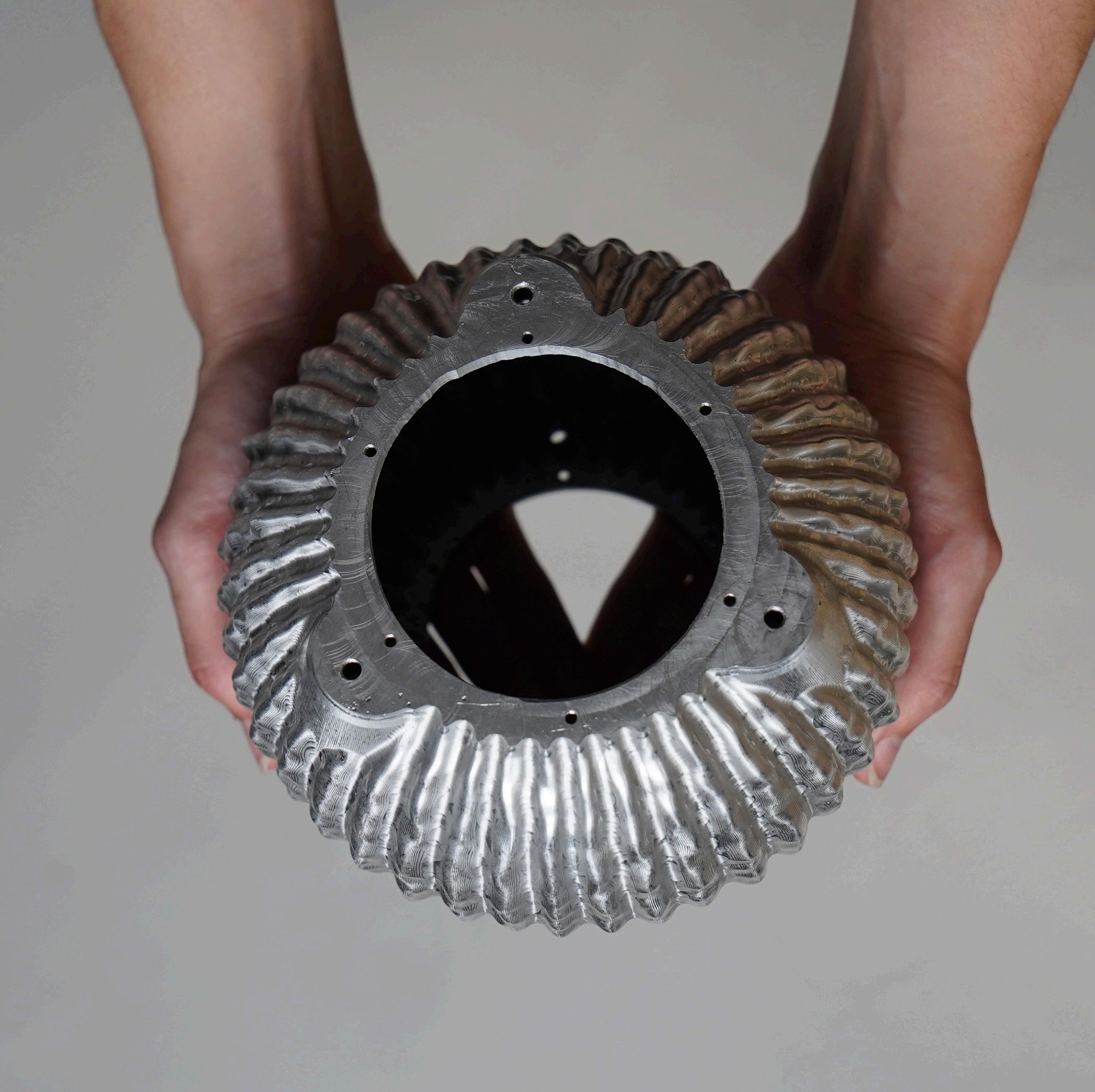
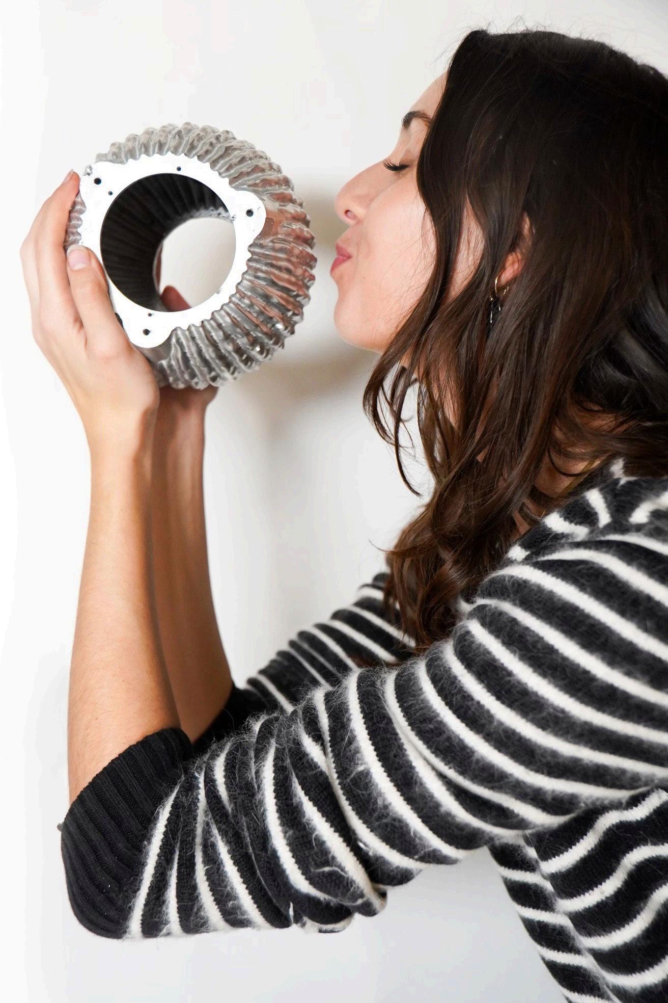
1: The Articulated Speaker I
Thank you to my supervisor, Professor Michael Stacey, for his continual reassurance and guidance. His passion for both aluminium and castings is definitely something I will carry with me for the rest of my architectural career. I would also like to thank Philip Beesley for allowing me to experience a small part of his world through this dissertation, and Dr Chris Leung for his insights into GPS.
The biggest thank you goes to Melis Van den Berg and Hamish Veitch, and all the staff at B-Made HereEast. Without Melis and Hamish, this dissertation wouldn’t have been possible; their expertise, advice, and patience carried the project from the outset, and for that I am eternally grateful.
Contents
Acknowledgements
Abstract
Chapter 01: Introduction
Introduction
Chapter 02: The Articulated Speaker
Collaborating with Philip Beesley
The Articulated Speaker
Aluminium as a Material
Casting Considerations
Chapter 03: Fabricating the Articulated Speaker
Analysing the Initial Articulated Speaker Design
Design Requirements
Modifying the Component for Manufacture
Aluminium Alloy Selection for Casting
Fabricating the Pattern
Fabricating the Core
Testing Through Casting
Post Machining
Chapter 04: Evaluating the Final Component
Casting Finish
Casting Defects
Pattern Misalignment
Core Misalignment
Machining Finish
Machining Errors
3D Scanning
Deviation Analysis
Manufacturing Issues
Scalability for Mass Production
Chapter 05: Looking to Further Research
Limitations
Further Research
Chapter 06: Conclusion
Conclusion
List of Figures
List of Tables
List of Abbreviations
Glossary of Terms
Bibliography
Appendix
This dissertation explores the role of prototyping and experimentation in architectural design through the fabrication of an articulated, cast and machined aluminium speaker developed in collaboration with Philip Beesley. The project interrogates the interdependencies between core design, sand casting, mould preparation, CNC machining, and tolerance control. Each stage of fabrication revealed how adjustments in one process shaped the constraints of the next, undermining the assumption of a clean linear workflow. The final component serves as a record of both success and failure, revealing where process, material and design intent converged and where they diverged. Through critical reflection on these outcomes, the dissertation positions ‘making’ as a generator of knowledge, rather than a means of validating pre-existing ideas. In doing so, it argues for an architectural practice that treats prototyping not as a supplementary phase, but as a central mode of enquiry shaping more precise, materially literate, and contextually responsive design.
Architecture today exists within a complex web of globalised exchange, where designers, fabricators, suppliers and materials span continents, yet the act of making remains profoundly local, tactile, and embodied. Prototyping is where design intent meets real world constraints, with experimentation operating as a necessary mode of enquiry. Through cycles of testing and adjustment, a project evolves, with innovation emerging as a response. The prototype becomes a space for invention, where experience leads to knowledge that cannot be simulated, only discovered (Sheil, 2005; Stacey, 2013).
This dissertation explores these ideas through the redesign and fabrication of an aluminium articulated speaker, developed in collaboration with Philip Beesley. Originally designed by Beesley as part of his wider body of immersive, responsive architecture, the speaker’s geometry was digitally modelled but required significant transformation to be realised physically. My role involved
translating this model into a viable cast component, navigating the complex demands of core design, mould preparation, sand casting and post-machining. The speaker became an index of its own making, each material decision legible in the final object.
Working within a set of design constraints defined by someone else altered the nature of decision-making. The shift from the 3D model to the material exposed the gaps between digital design and physical production. It was in these gaps that my role as fabricator expanded from executor to problem solver. In resolving form through process, I gained the ability to make informed decisions, shaped by growing knowledge of materials and their behaviour. The iterative nature of this work revealed a tacit form of understanding, one that emerges through doing (Sheil, 2005).
The dissertation situates itself within a broader argument: that direct engagement with tools and processes gives designers a more precise sense of what architecture is capable of. In the process of making, an architect learns how things behave, how they fail, and how they might be made better.
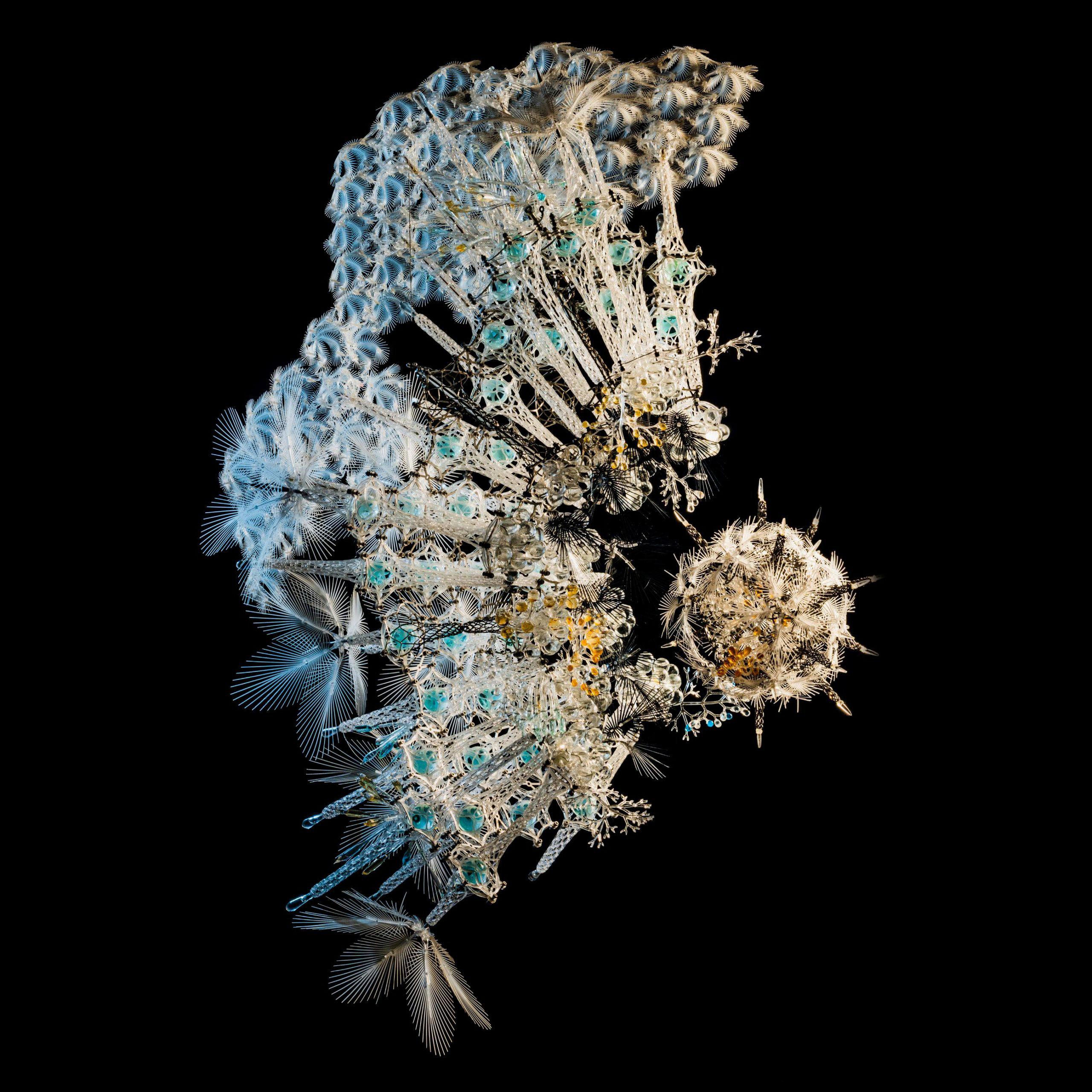
Collaboration underpinned the development of this dissertation, from working closely with the staff at B-made to engaging with Philip Beesley, the dissertation complied of a wealth of knowledge and input from a wide range of makers and specialists. Initial collaborations with Philip Beesley allowed for the dissertation to reflect the realities of designer-fabricator relationships and how, by the process of gaining an understanding of materiality and making, the fabricator can enact design decisions within the confines of the design brief, thus merging the roles of designer and fabricator. This collaboration provided a unique opportunity to engage with cutting-edge design concepts while contributing original research into fabrication processes.
Philip Beesley is an award-winning interdisciplinary artist, architect, and designer renowned for his research into Living Architecture. His work challenges traditional notions
of architecture as static, solid structures, advocating instead for systems that reflect the ever changing needs of human communities (Studio Philip Beesley, 2023). This dissertation builds on Beesley’s body of work, adapting one of his components for fabrication through aluminium sand casting. This is the only casting method available at B-Made and UCL.
Three component categories were considered for fabrication, each reflecting different aspects of Philip Beesley’s Living Architecture. The first category included heatsinks and a hanging tripod, both common components in Beesley’s installations. Whilst feasible, these components offered limited research value. The heatsinks’ flat bases allowed for single part moulds, and casting them in aluminium would follow conventional practice (Abbas, 2024). The tripod required a two-part mould and post-machining, but again, the process lacked challenge and novelty. The second category referenced Beesley’s longstanding collaboration with fashion designer Iris Van Herpen, comprising of intricate ornaments, similar to designs showcased in Iris van Herpen: Sculpting the Senses exhibition at the Musée des Arts Décoratifs (Studio Philip Beesley, 2023). However, their complex geometry and high aspect ratio would require significant redesign in order to cast, due to the high probability of early solidification in the thin cavities (Jolly & Katgerman, 2022).
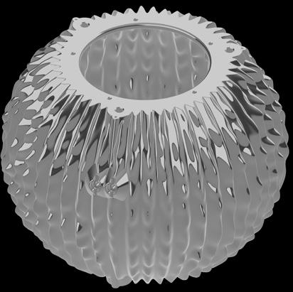
The third category, an articulated omnidirectional speaker, emerged as the most promising component. Designed to emit sound uniformly in all directions (Ibarra, Ledesma & Lopez, 2018), its hollow, articulated form allowed for adjustments to be made without losing the object’s function. Requiring a sand core and presenting meaningful casting challenges, it offered the ideal balance of complexity and creative freedom for the project.
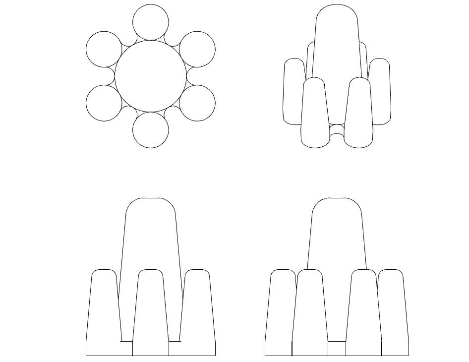
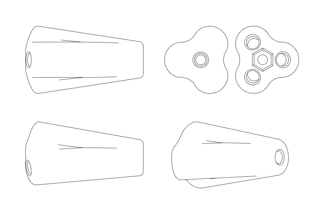
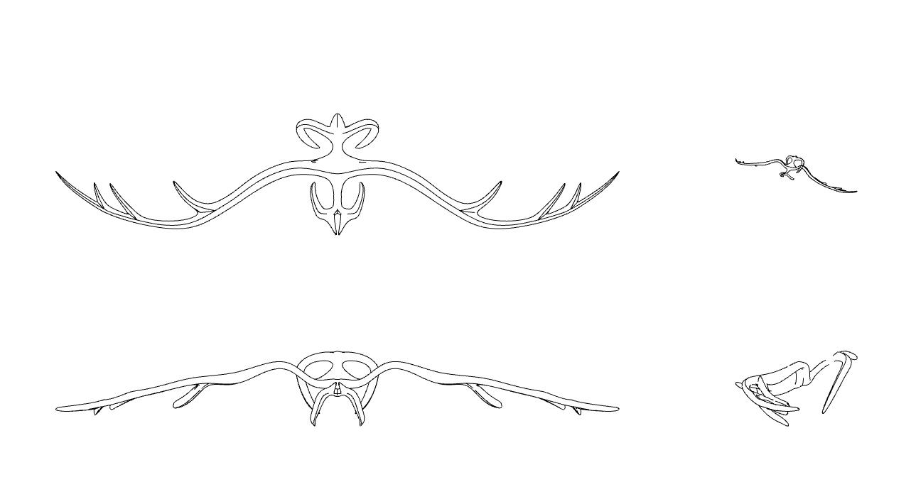
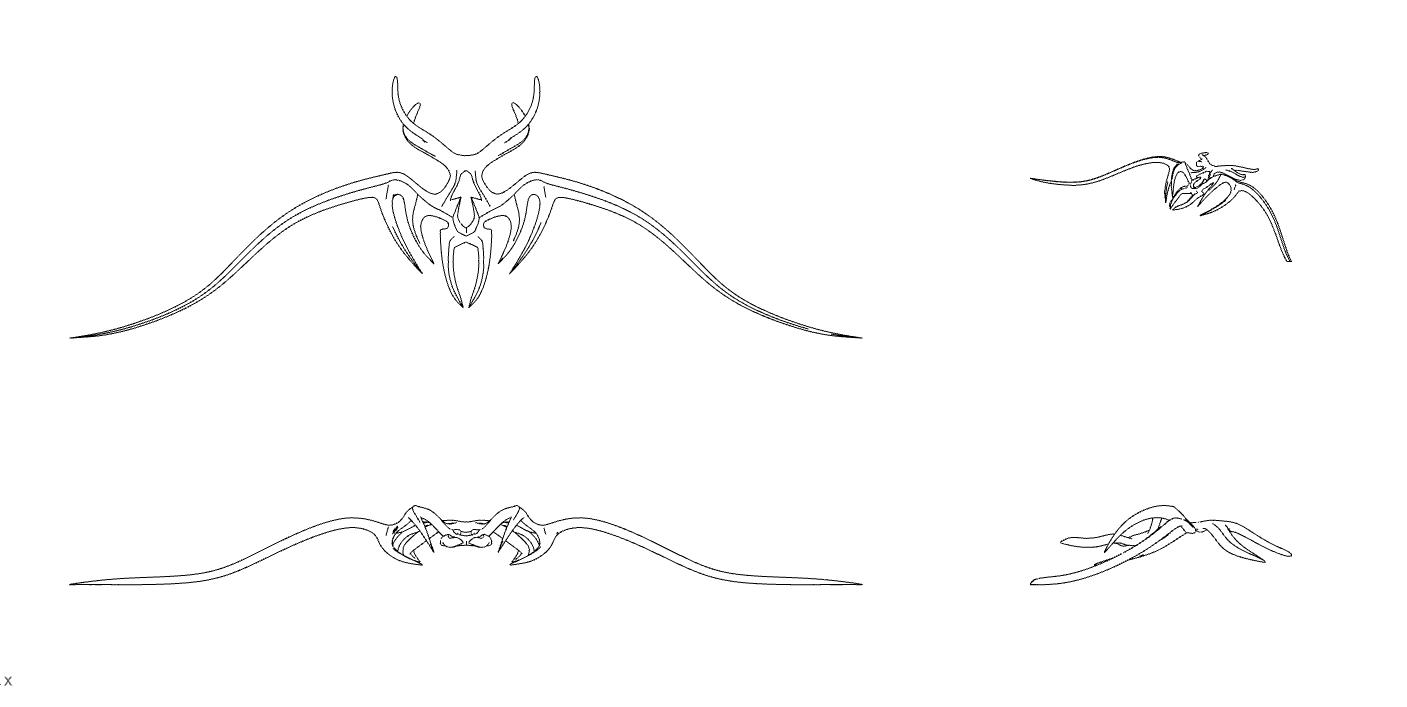
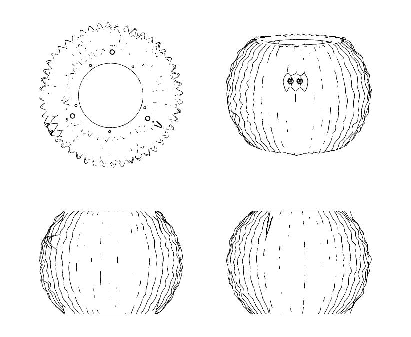

Beesley’s speaker is designed to be an omnidirectional speaker and diverges from the conventional through its articulated form, which is designed to cancel out resonance. By interrupting sine wave regularity, the design generates an aperiodic function, reducing standing waves and unwanted frequency peaks. While this improves the consistency of the sound output, true omnidirectionality requires more than the absence of resonance. Omnidirectionality demands uniform sound radiation and consistent sound pressure levels across all directions and frequencies. The speaker’s form and transducer arrangement reflect these requirements. A spherical geometry enables sound to radiate outward with minimal directional bias, while multiple drivers help to maintain balanced sound pressure across the audible spectrum (Quested et al., 2014; Chojnacki, Brzóska and Fijałkowska, 2023). This aligns with Beesley’s design philosophy, where technological and biological analogies inform the form, and each component contributes to the emergent behaviour of the whole system.
Omnidirectional sound sources have diverse applications across acoustic engineering, geophysics, and the music industry. In acoustics, their diffuse sound field properties make them ideal for tasks such as room measurements, reverberation analysis, and sound insulation testing, in line with ISO 3382-2 and ISO 16283-1 (Arnela, MartínezSuquía & Guasch, 2021). They are also used to analyse soil composition and detect manufacturing defects through acoustic reflections (Ibarra, Ledesma & Lopez, 2018). In the music industry, they provide flexible sound reinforcement, from large-scale events to compact vehicle systems. Typically, they feature spherical or polyhedral forms with multiple transducers (Arnela, Martínez-Suquía
and Guasch, 2021), most commonly a dodecahedron (Quested et al., 2014).
Sound is a tool used by Beesley across his installations throughout his body of work. Acting as a medium for heightened immersion, sound is used as a dynamic component that interacts with other sensory stimuli, such as light or movement. This approach aligns with his vision for Living Architecture, with spaces that respond to their occupants. The articulated omni-speaker exemplifies this, integrating functional and sensory experiences within architectural systems.
The initial iterations of the speaker were 3D printed by Beesley’s studio, a method that supports rapid prototyping. Figure 4 shows some of these 3D printed speaker casings in the context of Beesley’s installations. This dissertation makes a case for casting a version in aluminium, offering a material alternative that supports both functional performance and expressive form. Aluminium is a lightweight, corrosion-resistant metal that comprises around 8% of the Earth’s crust (Dwight, 1999). When looking at aluminium as a material, its scope is very broad. Aluminium is highly formable. It can be cast, extruded, welded and milled (Stacey, 2023). It can also be alloyed to improve its material properties (Stacey, 2023). These factors, in tandem with its low density (2.70 g/cm³) and high strength-to-weight ratio, make it an ideal material for fabrication at a range of scales and applications (Dwight, 1999). This range sees aluminium found across consumer goods, construction and transport industries (Stacey, 2023).
Aluminium is typically extracted from the bauxite ore through a three stage process: first, the ore is mined; next, the Bayer process refines it into alumina (Al₂O₃); finally, the Hall-Héroult process uses electrolysis, combined with a high electrical input, to produce 99.5 - 99.8% pure aluminium (Dwight, 1999). The process to achieve pure aluminium is highly energy-intensive and expensive. The main requirements for aluminium production are bauxite, a source of heat energy, and access to low-cost electricity. These elements are rarely readily accessible in the same location, meaning the need for transportation between stages increases both costs and embodied carbon. Despite the initial high energy usage, aluminium is close to infinitely recyclable with little loss in material quality (Stacey, 2023). Recycling scrap aluminium consumes just 5% of the energy needed to produce aluminium from raw materials, with primary aluminium having embodied carbon levels of 16 t CO₂e/t and secondary (recycled) aluminium just 0.5 t CO₂e/t (Institution of Structural Engineers, 2024). Its value as a material for the future is most evident when assessed through a Life Cycle Assessment (LCA), which highlights its full potential within a circular economy (Stacey, 2023).
Finishes are an important consideration when working with metals. Metals like steel can rust over time, however, aluminium is naturally resistant to corrosion (Dwight, 1999). This is due to the thin (typically 0.005 mm), hard oxide layer that forms when aluminium is exposed to air (Dwight, 1999). The oxide layer is chemically stable, tightly bonded to the surface, and is self-regenerating in the presence of oxygen, preventing further oxidation and giving aluminium its excellent durability (Dwight, 1999). Further finishes can be applied to aluminium, with components typically finished using one of three methods: anodising, polyester powder coating (PPC), or wet paint systems such as polyvinyl fluoride (PVDF or PVF2) coatings (Stacey, 2023). These
can provide more resilient protection against corrosion or improve the appearance of the surface finish.
“While resonance defines musical instruments, it must be eliminated in speaker design to achieve true sonic neutrality” - MAGICO founder Alon Wolf (MAGICO, n.d.)
Aluminium is an ideal material for Beesley’s articulated speaker due to its unique combination of lightness, strength, and machinability. The speaker’s complex form demands a material that can be cast into intricate geometries whilst being compatible with post-processing methods, such as CNC (Computer Numerical Control) machining, allowing for precise refinement postcasting (Dwight, 1999). Furthermore, aluminium’s corrosion resistance provided by its oxide layer ensures the component can perform reliably in a range of environmental conditions, as well as having a desirable and consistent finish (Dwight, 1999). In the broader audio industry, aluminium is widely favoured for high-performance speaker enclosures. Figure 5 shows the performance of aluminium acoustically in comparison to other common speaker housing materials, showing its superiority. Highend audio manufacturers like MAGICO have pioneered the use of aluminium in the design of speaker casings. The stiffness, mass, and damping potential of aluminium are key characteristics as to why it performs so well for sound performance (MAGICO, n.d.). These features help minimise unwanted vibrations and resonance that can distort sound, resulting in a cleaner audio experience (MAGICO, n.d.). Aluminium’s sleek appearance and adaptability to various finishes also make it a popular choice in consumer audio design, where both acoustic performance and aesthetics are essential.
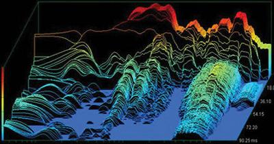
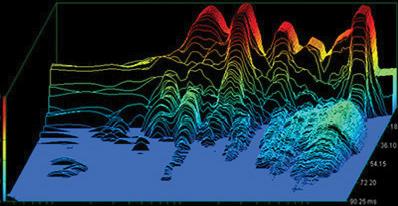
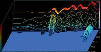
Figure 5: Graphs showing spectral decay data for typical speaker casing materials (MAGICO, n.d.)
The process of casting offered the freedom of form that enabled the component to resolve complex assemblies and geometric challenges within a single, unified component (Stacey, 2001). Containing the speaker casing to one singular component also helped reduce resonance from vibrations due to additional components (MAGICO, n.d.). Casting offers architects an opportunity to re-engage with craft within the built environment, offering an affordable and durable solution to create expressive, high quality 3D components with tailored structural performance, efficient material use, and the potential for fine finishes and tight tolerances, depending on the casting method (Stacey, 2001). Casting is a manufacturing technique by which molten material, most commonly metal, is poured into a mould and left to solidify, forming components with defined shapes and dimensions (Baddoo, 1996). The primary casting methods include sand casting, die casting, lost foam casting, and lost wax casting, each suited to specific applications depending on factors such as complexity, finishes and production volume (Stacey, 2001).
“Foundries are a fascinating cross between Danté’s Inferno and a wonderland of lost components.” - Michael Stacey (2001)
Foundry practices date back thousands of years, with early civilisations using techniques like lost wax casting and sand casting to produce tools, jewellery, and ceremonial objects (Nordez, 2024). These traditional methods laid the foundation for modern casting, and many of the core principles, such as mould-making and molten metal handling, remain in use today. While contemporary foundries now employ advanced technologies like CAD modelling, flow simulation, and automation to improve precision and efficiency, the essence of ancient foundry work endures (Stacey, 2001). This continuity reflects a
balance between historical craftsmanship and modern innovation, allowing the process to evolve without losing its artisanal roots.
Casting Method Advantages Disadvantages
Sand Casting
Investment Casting
High design flexibility (size and weight);
High-complexity shapes; Wider material choice;
Low-cost tooling
High precision is obtainable; Intricate and complex shapes are achievable; Provides excellent surface finishing; Little or no machining is required
Low strength; Low dimensional accuracy; Poor surface finish; Post-machining
Cast size limitation; High cost of production
Die Casting
Thin wall parts can be cast; Close tolerance is possible; Excellent surface finishing; Economical for mass production
Gases can be trapped and cause porosity; Cast size is limited; Not suited for high melting point metals; Tooling cost is high
Table 1: Casting Comparisons (Adeleke et al., 2022)
As this component was to be fabricated at the University College London HereEast B-Made Workshop, there were some limitations when choosing a casting method. Lost wax casting would have been an ideal method for this component, due to the complex geometry and high-quality
finish desired. However, there were no facilities that could accommodate the fabrication of the wax pattern. Lost foam casting can be used with Polylactic Acid (PLA) patterns, a 3D printing filament that vaporises upon contact with molten metal (Jem and Tan, 2020). While this would allow for on-site pattern production, the volume of fumes (Romanowski et al., 2023) produced during vaporisation exceeds extraction capacities, making the process unsuitable for indoor environments such as the HereEast Workshop. Therefore, given the facilities available, sand casting was the chosen casting method. Table 1 provides further comparisons between the three casting methods explored. The process of sand casting involves packing sand around a pattern and then stabilising the mould with binders such as clay, resin, or silica compounds before filling the mould with molten metal (Bralla, 2000). After the metal cools and solidifies, the sand is broken away to reveal the casting. Sand casting is very useful due to its versatility, but generally produces a rough surface finish that requires additional machining (Stacey, 2001). It is a method ideal for large-scale or simple components, such as engine blocks, industrial machine parts, and structural nodes (Stacey, 2001). Sand casting is also a very cost-effective method of casting, making it highly suitable for one-off or low-volume production (Weiss, 2018). For the nature of this dissertation, it allowed for experimentation and prototyping without the risk of high costs.
Before the fabrication of the speaker could commence, the manufacturability of the original component had to be assessed. When looking to achieve a successful sand cast, the first step is to design a considered pattern. The pattern dictates the shape of the casting. Two of the most important factors are the draft angles and the parting line of the pattern’s two halves of the mould. Draft angles are necessary for sand casting to ensure the mould can be easily removed from the sand without causing breakages or defects in the casting (BSI, 1996). The draft angle compensates for the friction between the pattern and the sand as the pattern is withdrawn. The required draft angle depends on the moulding method, the pattern design, the material of the pattern, the level of precision needed, and the pattern’s surface smoothness (Bralla, 2000). In cases where designs have undercuts or no draft angles, castings can only be produced by including separately made cores
in the mould, which increases the cost (Bralla, 2000). The parting line is the continuous line dividing the two halves of a mould (Bralla, 2000). Positioning the parting line on a flat plane is ideal for castings, as it produces more economical and precise results, however, contoured parting lines can be considered, but often lead to less successful castings, due to higher pattern costs and decreased accuracy (Bralla, 2000).
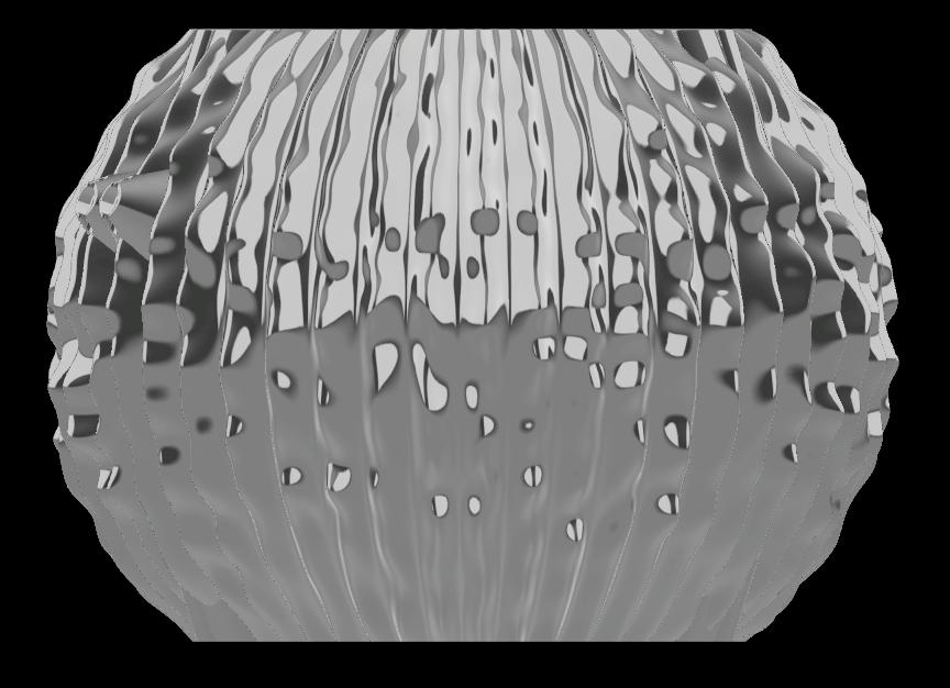
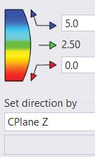
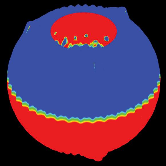
When looking to sand cast Beesley’s articulated speaker component, the complex geometry meant that when analysing the draft angles and parting line using the Rhinoceros 3D DraftAngleAnalysis function (McNeel, 2015), there were a large number of undercuts and no clear, flat parting line, as seen in Figure 6. These factors would lead to an unsuccessful cast. Therefore, measures had to be taken to both redesign the speaker and further consider the fabrication methods needed to achieve Beesley’s design intentions.
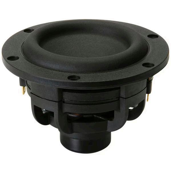
The scale of the original articulated speaker was likely to make manufacturing slower and more difficult. The size meant that the pattern for the component could not be printed in one part using the available Ultimaker Cura 3D printers at B-Made, as the scale would exceed the bed capacity, and printing times had the potential to exceed multiple days. This, in tandem with the limitations of the volume capacity of the crucible, where the aluminium is melted, and the difficulty in manoeuvring the weight of a large cope and drag, led to the decision for the articulated speaker to be redesigned as a smaller, but still 1:1 component for a miniature subwoofer driver. This would save material, simplify the manufacturing process and add another component to Beesley’s universe of Living Architecture.
Isometric SW view 1:2
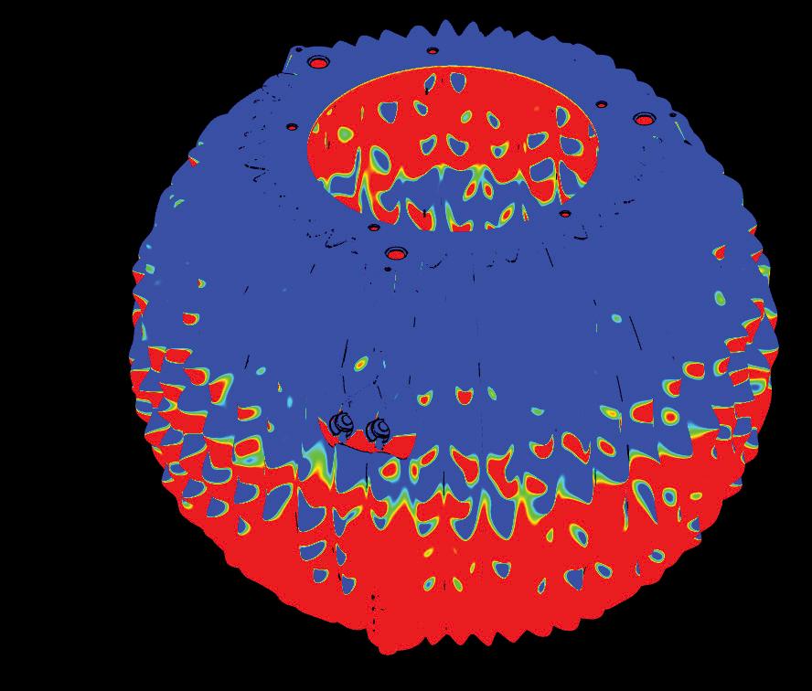
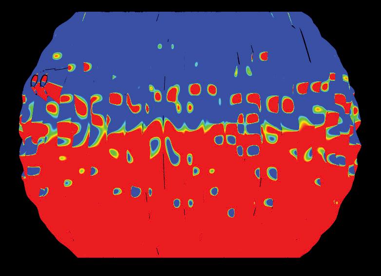
5.00 2.50 0.00
degrees
Following this decision, the design requirements were set out by Beesley, as seen in Table 2 . Once the constraints of the task at hand had been established, options were explored for how the component could be fabricated. One of the initial options discussed was to use a contoured parting line. The more pronounced the contouring, the greater the associated challenges and costs (Bralla, 2000) and in this case, the parting line contours would have to be particularly pronounced, due to the object’s complexity. Additionally, a contoured parting line alone would not have solved all the undercuts, meaning further measures would still have had to be taken. The combination of these factors led to the decision to choose a flat parting line and reconsider how these undercuts could be tackled using alternative methods.
The next method explored relied on looking at alterations that could be made to the geometry of the component
Hole pattern PCD's
Design Feature
Speaker Driver
Internal Volume
Holes for speaker driver attachment
Holes for mounting system attachments
Design Requirement Image
Tang Band W3-1876S 3" Mini Subwoofer
https://www.parts-express.com/T ang-Band-W3-1876S-3-Mini-Sub woofer-264-909
The banana jacks should be insulated. The banana jacks are to be a 3D printed insert to avoid the aluminium cast bridging and shorting the two banana jacks
The recommend sealed volume for Tang Band W3-1876S is 0.03ft³, thus the inner volume for the double driver subwoofer should target 0.03ft³*2 = 0.06ft³
Two sets of holes should be on each opening
The smaller set being the mounting holes for the speaker driver, sitting in between the inner and outer shell (4-40 thread)
Two sets of holes should be on each opening
The larger set being attachment points for the mounting system (10-24 thread)
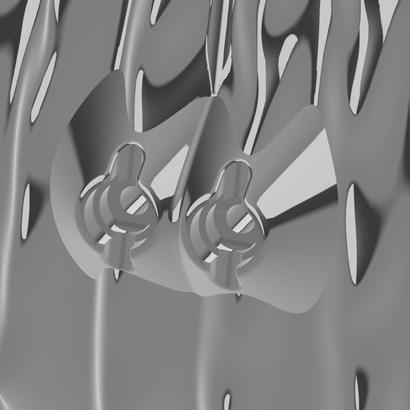

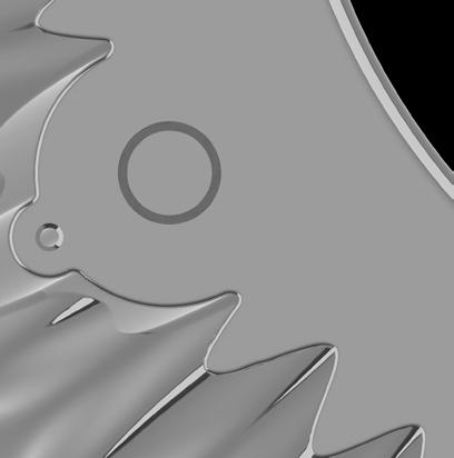
Holes at openings
The two openings of the dual driver subwoofer should be identical and symmetrical
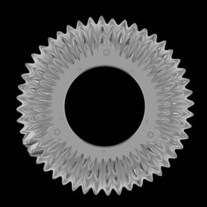
to achieve a flat parting line and remove any undercuts. Beesley provided the Grasshopper script that could create the speaker’s articulated function. There were a number of factors that had the capacity to change the form, which were all individually tested. These included the number of ribs and the noise levels of the articulations. The only scenario where a flat parting line with no undercuts could be achieved was when the noise levels were set to zero. As the articulations and aperiodic nature of the form provided such a large part of the function in reducing resonance, further methods had to be explored once again. Adjusting the script to meet at a central flat parting line was a further method considered, however, this would not prevent all the undercuts from arising.
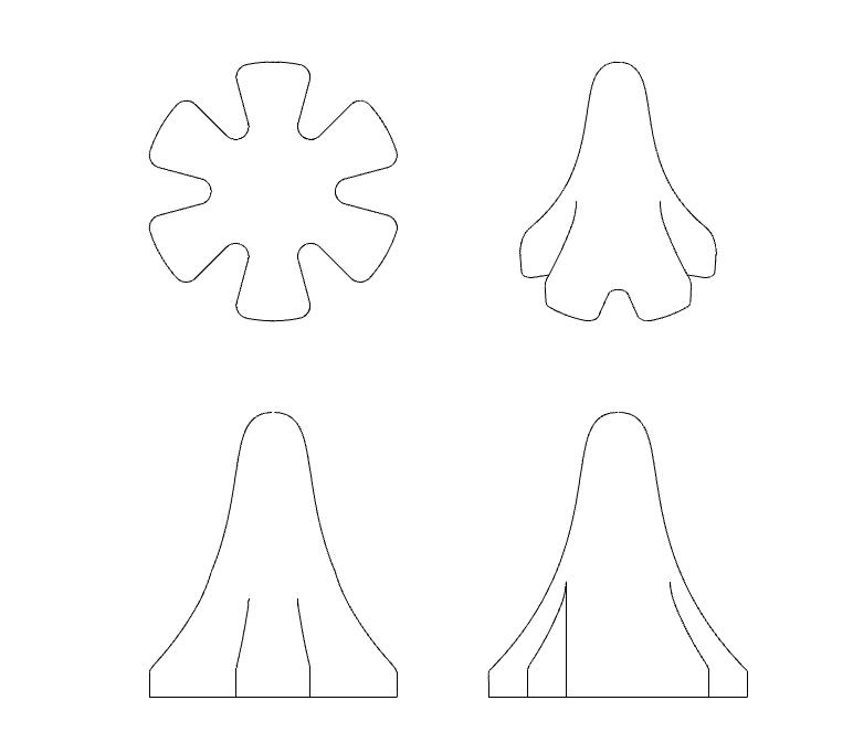
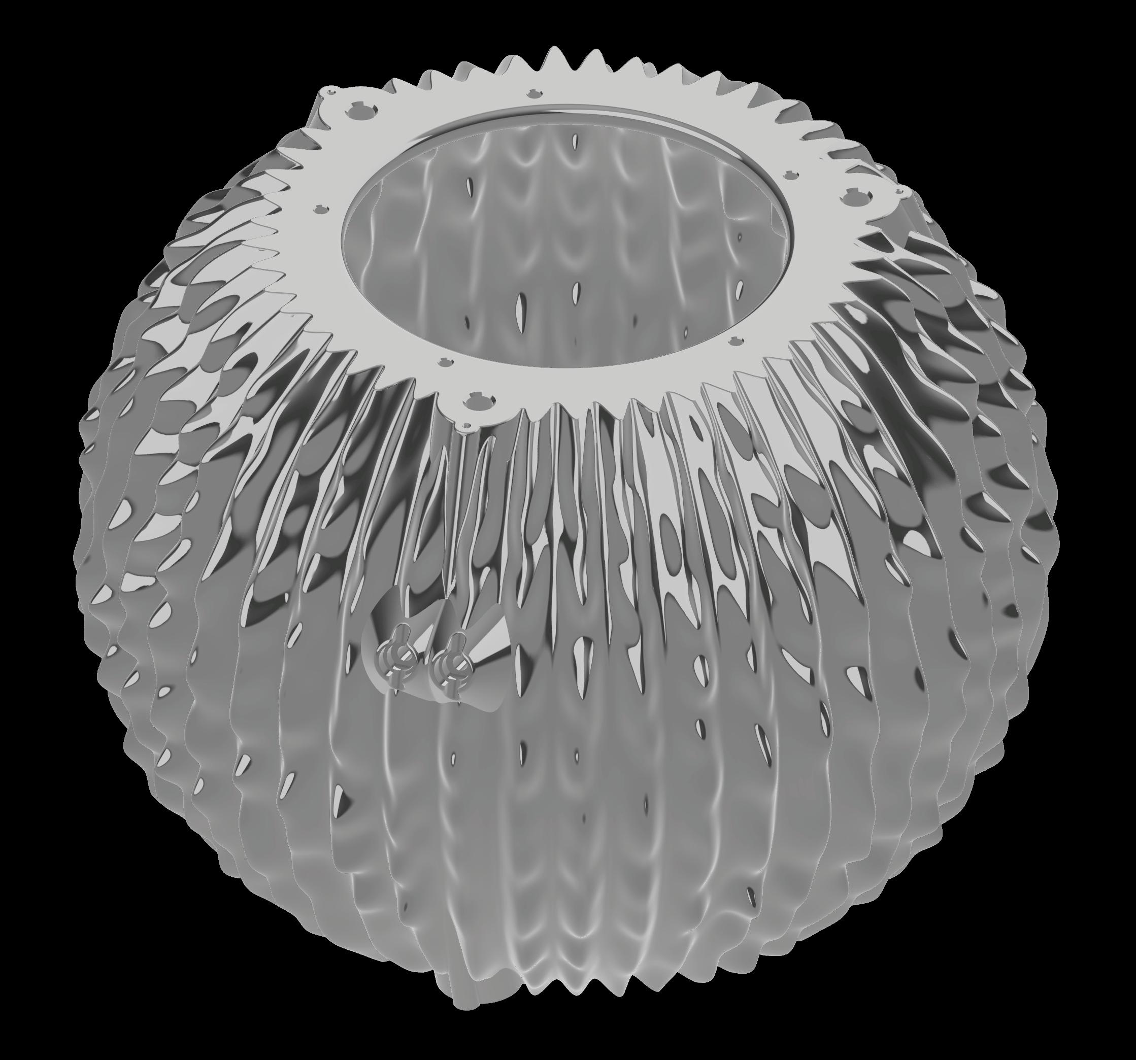
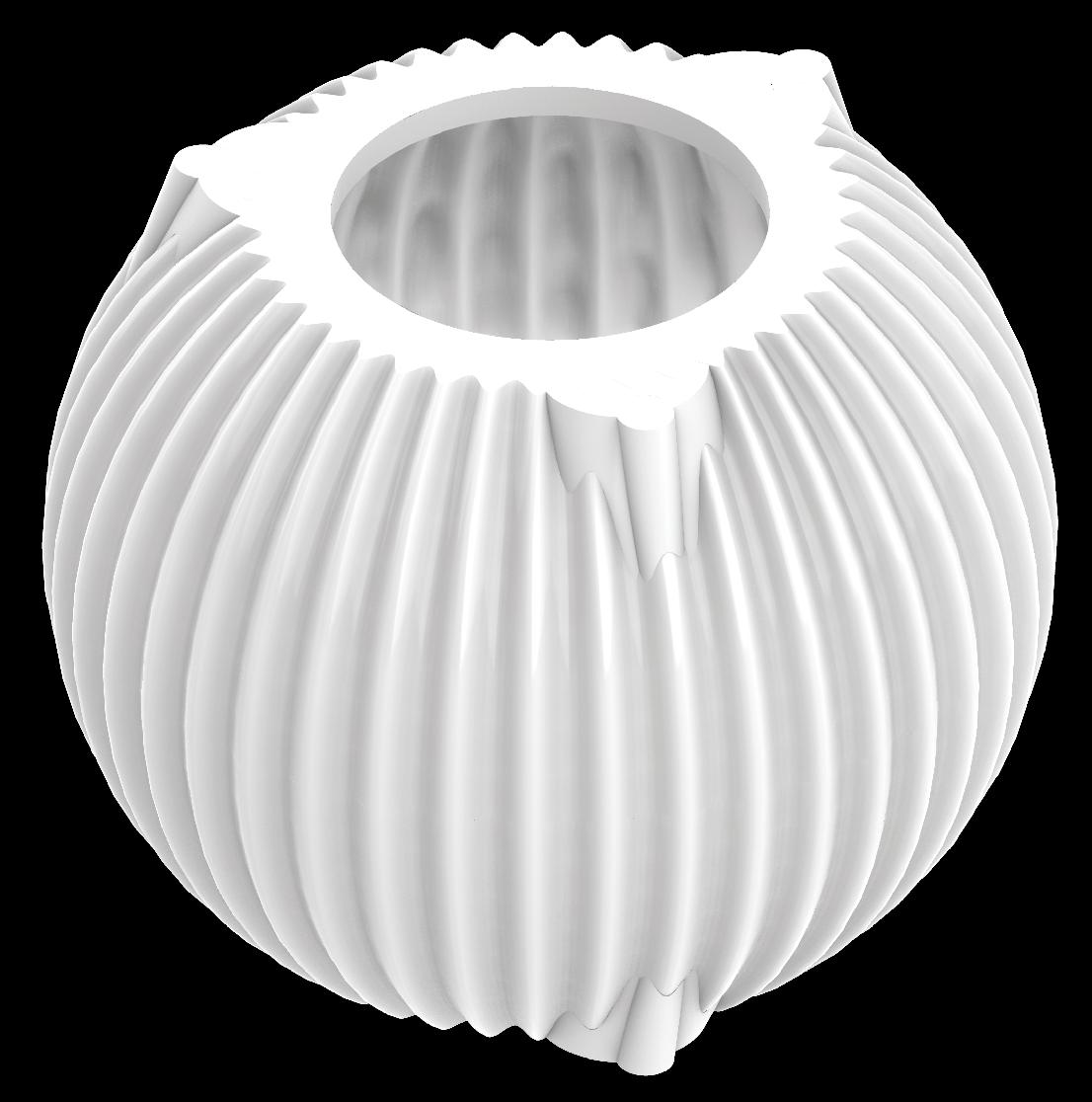
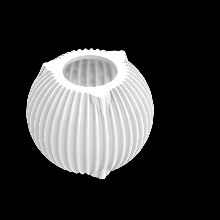
Sand casting often relies on post-machining (Stacey, 2001). The final and chosen method explored using further fabrication methods to post-machine the component after it had been cast. A sand core would provide the internal articulations for the speaker, as cores can achieve forms with undercuts within the casting process (Bralla, 2000). This meant that the pattern would take the form of the aperiodic function when the noise levels were set to zero, as seen in Figure 7. Figure 8 shows the drawings for the final redesigned speaker, laying out the design intentions.
The next design decision focused on selecting the aluminium alloy for casting the articulated speaker. Alloy selection and casting design are inherently interconnected, with both influencing the performance and outcome of a casting. The chosen casting method plays a critical role in determining the most suitable alloy. Designed specifically for casting processes, Lynall Metal (LM) alloys offer a balance of mechanical strength, corrosion resistance, and finish quality, with compositions suited to both sand and die casting. Among the LM series, LM27, LM25, LM20, LM6 and LM4 are most commonly used in sand casting, with LM25, LM6 and LM4 performing best (Aluminium Alloy Manufacturing & Recycling Association, 2018).
The selection of an aluminium alloy must begin with a clear understanding of the component’s functional requirements: its geometry, performance, environmental exposure, and post-processing needs. In casting, alloy choice governs not only mechanical behaviour but also how fluidly the metal will fill a mould, how it will respond to machining or heat treatment, and how it will endure over time (Aluminium Alloy Manufacturing & Recycling Association, 2018). Alloys are selected not in isolation but as a consequence of a project’s material, manufacturing, and maintenance needs.
The speaker casing demanded an alloy that enabled thin walls and articulated geometry, offering stability during and after casting, and maintaining its surface integrity over time. Alloys offer significant advantages over pure metals, as they enhance specific material properties, with the performance of the alloy being tied heavily to its composition. A high silicon content improves casting characteristics and shrinkage but reduces machinability, magnesium and copper enhance strength but may compromise corrosion resistance, nickel improves
thermal stability, and manganese alters grain structure and shrinkage resistance (Aluminium Alloy Manufacturing & Recycling Association, 2018). Understanding these relationships is central to alloy specification.
Tables 3 and 4 compare the compositions and properties of LM4, LM6 and LM25. LM6 was ultimately the chosen alloy for the articulated speaker due to its suitability to the complex, hollow form attributed to its exceptional fluidity and resistance to hot tearing, qualities derived from its high silicon content (Aluminium Alloy Manufacturing & Recycling Association, 2018). These characteristics ensure that the mould fills completely, even around fine articulation points and internal cores, to deliver a consistent surface finish. Although machinability is more limited, this can be managed through the use of large cutting angles, adequate lubrication and carbide tools, to achieve a precise finish where required (Aluminium Alloy Manufacturing & Recycling Association, 2018). LM4 presents improved hardness and machinability, though with reduced fluidity and corrosion resistance, making it less suitable for exposed contexts and the least suitable for the speaker (Aluminium Alloy Manufacturing & Recycling Association, 2018). LM25, by contrast, provides superior mechanical strength and machinability, especially when heat-treated, making it appropriate for applications demanding tighter tolerances or higher structural performance. However, its reduced fluidity limits its effectiveness for intricate casting like the speaker(Aluminium Alloy Manufacturing & Recycling Association, 2018).
Table 3: Adapted Table of Comparison of LM4, LM6 and LM25 Aluminium Alloy Composition (Aluminium Alloy Manufacturing and Recycling Association, 2008)
Table 4: Adapted Table of Comparison of LM4, LM6 and LM25 Aluminium Alloy Properties (Aluminium Alloy Manufacturing and Recycling Association, 2008)
When fabricating the pattern for the casting, CNC milling and 3D printing were considered. 3D printing was the chosen method, due to the ease at which rapid prototyping could occur. 3D printing is also particularly beneficial for low volume or one off patterns which have complex geometries, such as the articulated speaker. Material extrusion 3D printing builds the pattern layer by layer, allowing for undercuts with the build-up of supports without the need for additional tooling or assembly, which would be necessary for CNC milling (Shahrubudin, Lee and Ramlan, 2019).
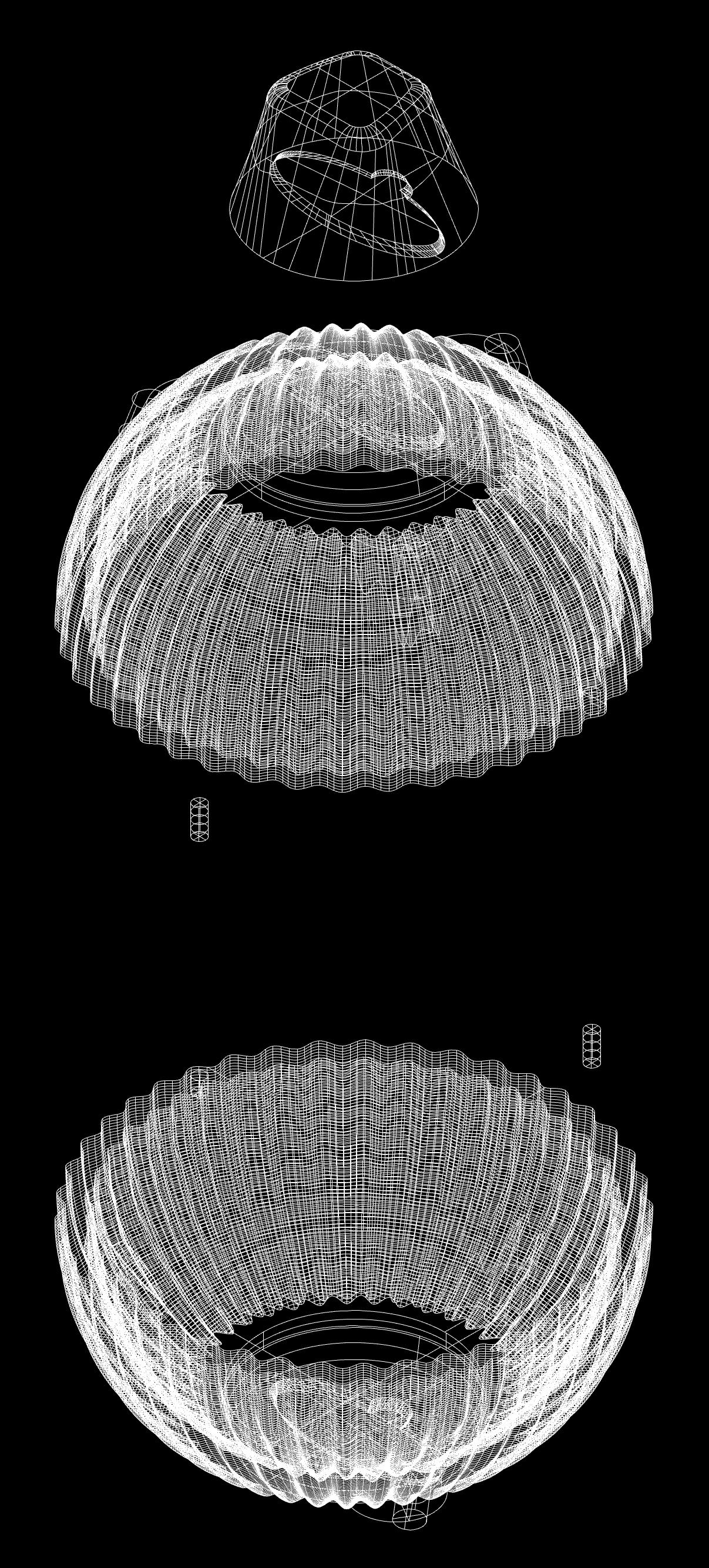
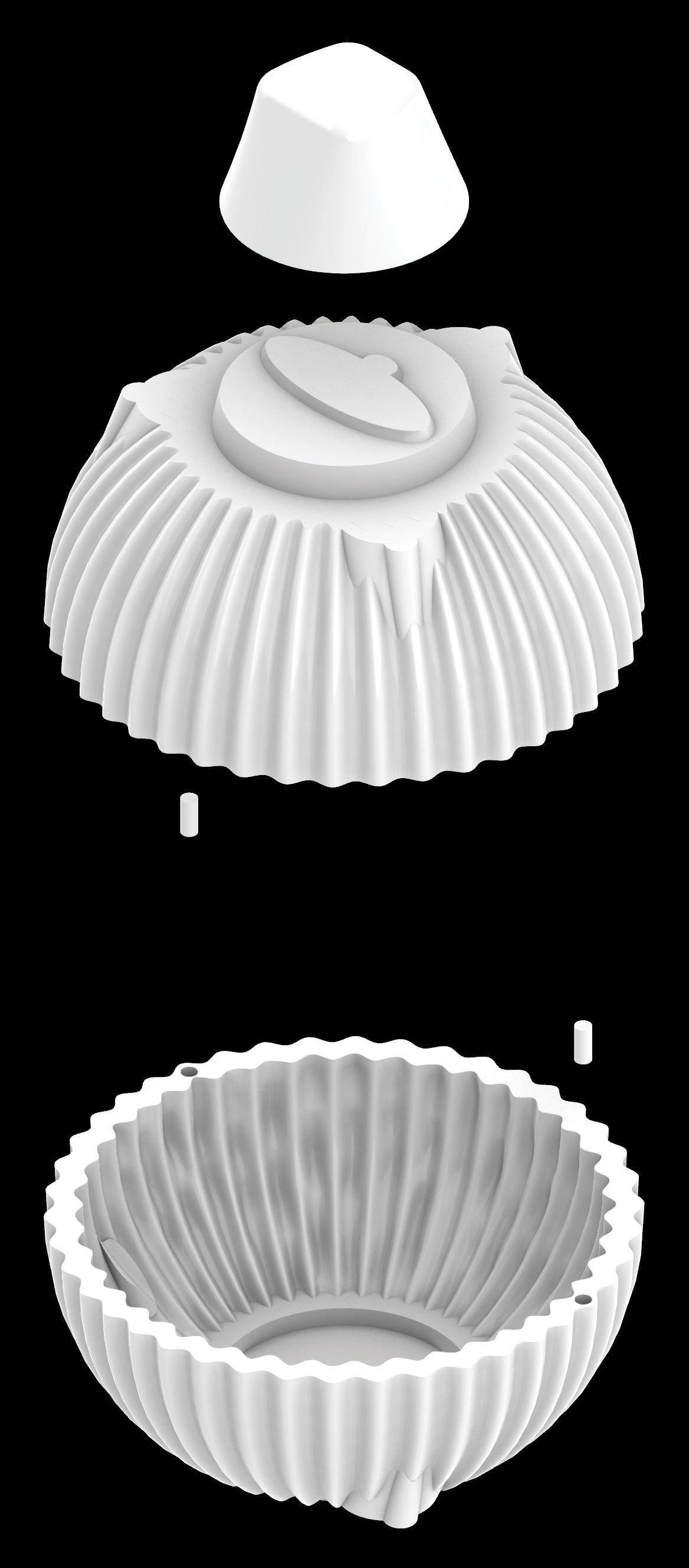
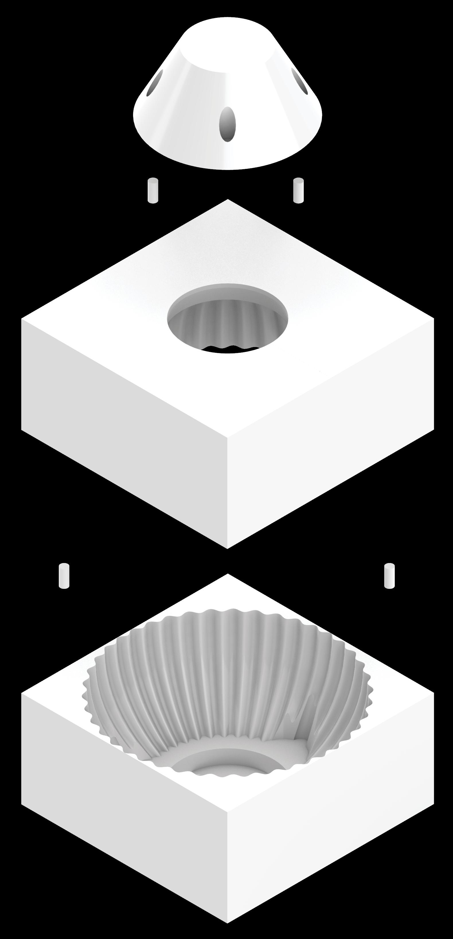
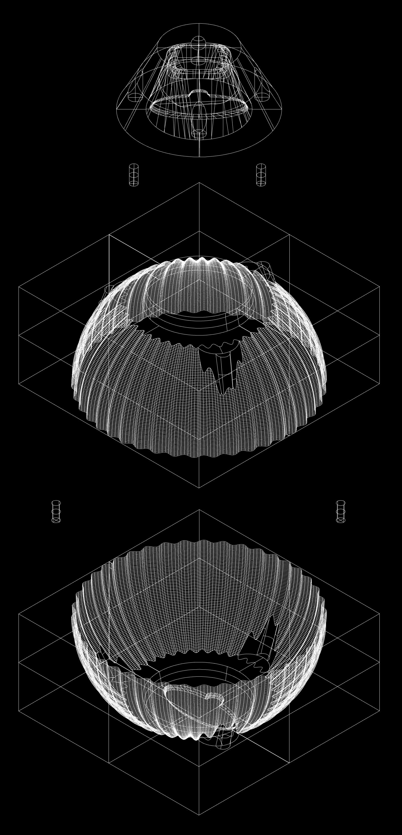
Before 3D printing could occur, the pattern had to be optimised for casting. This involved accounting for the 3.7% shrinkage of the LM6 aluminium alloy (Aluminium Alloy Manufacturing & Recycling Association, 2018) that occurs when the molten metal solidifies (Bralla, 2000) and accordingly scaling the computer-aided design (CAD) model from its centre of mass (Leung, 2023). In addition to this, a stock allowance had to be added to the surfaces that were going to be machined (Bralla, 2000). This would allow for any surface variations that may arise during the casting process and ensure the accuracy of the final component. Finally, aligning holes were inputted into both parts of the CAD model so dowels could be used to ensure the pattern could be slotted together. These holes were positioned so there was only one way the two sides could slot together correctly. This helped to ensure that the articulated pattern would align.
Casting patterns are most commonly made from wood, however, plastic and metal are also viable options, particularly when longer production runs are likely (Baddoo, 1996). In this case, as the pattern was being fabricated via 3D printing, PLA was used. PLA is a bioplastic, made from bio-based sources with biodegradable properties (Jem
and Tan, 2020). It can degrade in a matter of months, as opposed to conventional plastics, which can take hundreds of years, but it can also be reused, due to its material integrity, making it ideal for testing multiple patterns (Jem and Tan, 2020). 3D printed plastic patterns also offer a relatively fine finish.
Once the geometry had been optimised for 3D printing, it was exported as an *. stl file. This creates the G-code required to run the print through the Ultimaker CURA software (Leung, 2023). Due to the complexity of the component and the number of supports required, each part of the mould took over a day to print. This print time was reduced by reducing the infill and support density in the advanced settings of the software, in turn reducing material usage and associated costs.
Once the pattern had been 3D printed, the supports were removed with pliers, leaving the final pattern. Where the density of the 3D printing settings had been kept higher, the quality of the finish was also higher. Despite this, a Hycote Primer was applied to the surface of the pattern that was to be in contact with the sand in order to ensure the pattern was as smooth as possible to reduce any friction between the pattern and the sand. After allowing 24 hours for the primer to dry, the pattern was sanded to further ensure the surface’s smoothness.
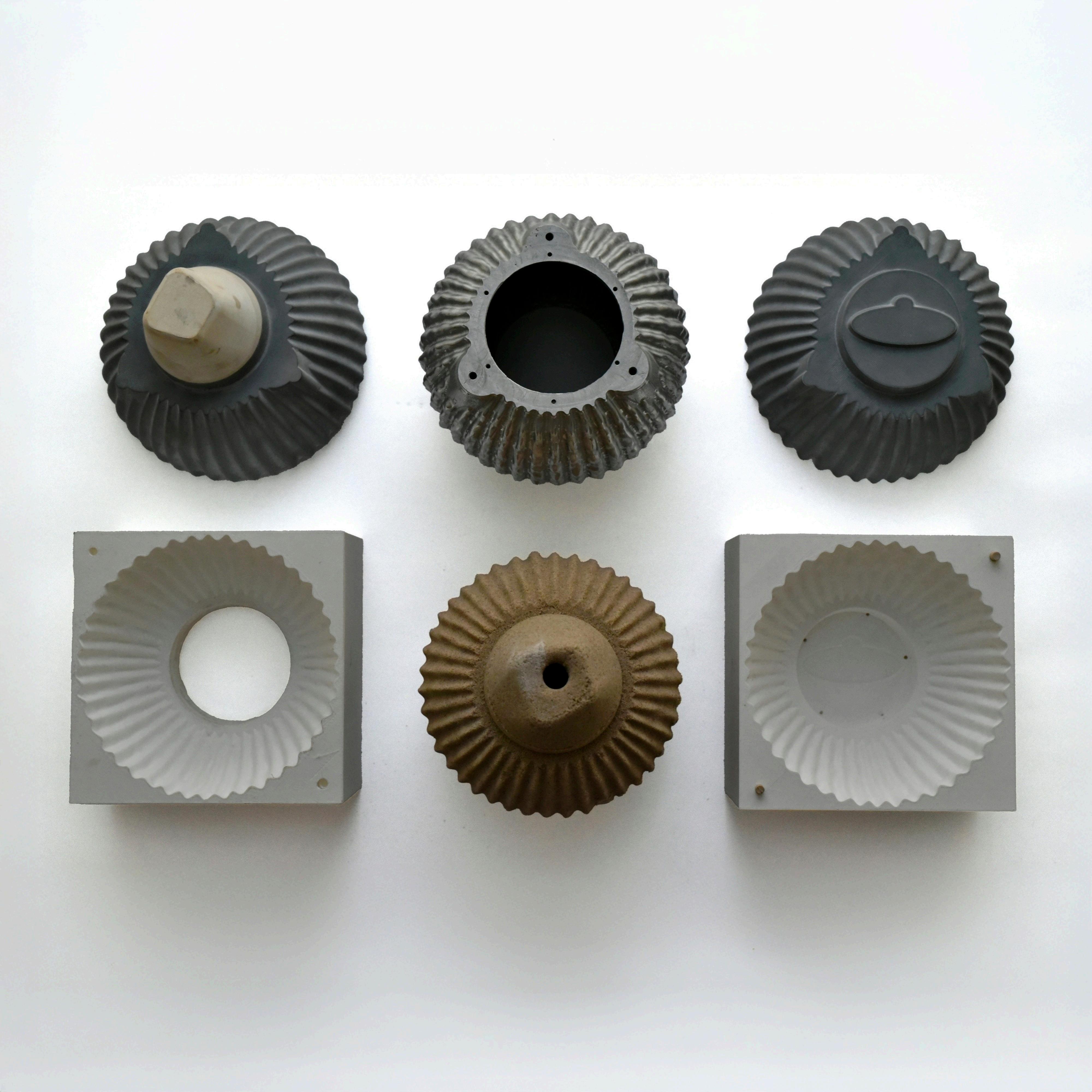
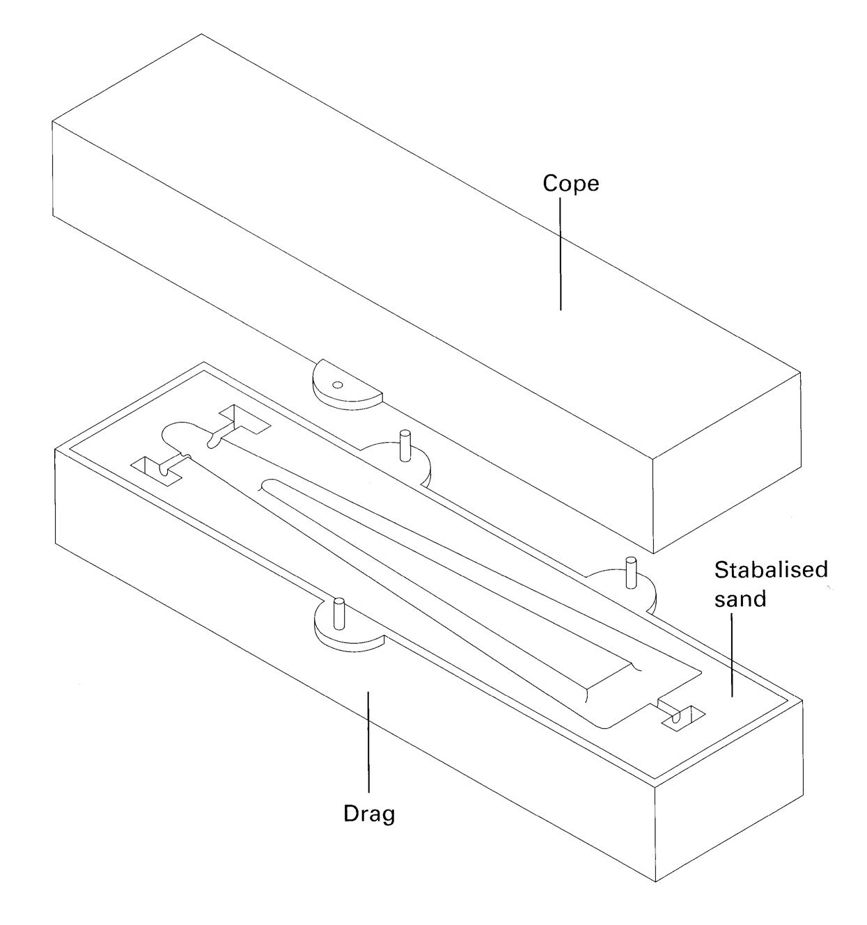
9: Diagram of the Components Required to Create the Casting, Photograph (Leung, 2025)
The next factor to consider was the core. Sand cores are used in casting to create internal cavities or hollow sections within a component that cannot be formed by the external mould alone (Baddoo, 1996). They are often complex in geometry and are generally avoided in industry, where possible, due to their great expense (Bralla, 2000). However, often cores are essential for the designed component. Cores are the ‘dark art of casting’ and are part of the reason a foundry worker typically undertakes a seven-year apprenticeship (Stacey, 2025).
Sand cores can be produced using a variety of methods, each suited to different production contexts, geometries, and levels of complexity. Ramming, the most traditional approach, involves manually or mechanically compacting binder-enhanced sand into a core box. While simple and cost-effective, it is best suited for small batches or relatively straightforward forms due to its lower precision. Core blowing is a much more consistent alternative, using compressed air to inject sand into the core box at high speeds. This makes it ideal for high-volume production runs. Additive manufacturing (AM), such as 3D printing, allows for the creation of highly complex cores, however, the process for this is slower and more expensive, making it most effective for prototyping or low-volume runs (Almaghariz, 2015).
Regardless of the forming method, the core is typically made from a binder-enhanced sand mixture, shaped in a core box, and then hardened either by air-set binders, heat, or gas (Deore et al., 2015). Once cured, the core is removed and placed in the mould cavity, where integrated locators ensure correct orientation and stability. During casting, molten metal flows around the core; after solidification, the core material is broken away, leaving the
intended internal void. As cores are subjected to intense heat and pressure, their design must ensure structural integrity under these conditions while also allowing for effective gas evacuation to prevent defects such as porosity or trapped air (Bralla, 2000; Baddoo, 1996).
The choice of curing method further affects core performance. Techniques include oil-bonded, resinbonded hot-box and cold-box, shell cores, and sodium silicate CO₂ cores. While shell cores offer high dimensional accuracy and excellent surface finish, they are expensive and best suited to industrial-scale production. Cold-box cores provide consistent strength but involve toxic or odorous gases such as amines or SO₂, requiring complex extraction systems (Deore et al., 2015). In contrast, sodium silicate CO₂ cores cure through exposure to carbon dioxide, producing dimensionally stable cores without toxic emissions or the need for post-curing, making them particularly suitable for safe and efficient use in a workshop setting (Deore et al., 2015).
The first iteration of the 3D-printed core box proved unsuccessful, as the locator was insufficient to properly stabilise or orient the core within the mould. Without a secure locating mechanism, there was a risk of the core shifting during assembly or casting, which could compromise the accuracy of the internal cavity. To resolve this, an additional insert was designed and printed to attach to the core box, acting as a more reliable locator. This insert was attached to the core box using wooden dowels so it could be removed in order to easily pack the core box with sand. A corresponding positive was glued to the pattern to ensure that the core could seat securely and consistently within the mould cavity. This adjustment allowed the core to be correctly positioned and stabilised during the casting process, improving both the reliability and precision of the final component.
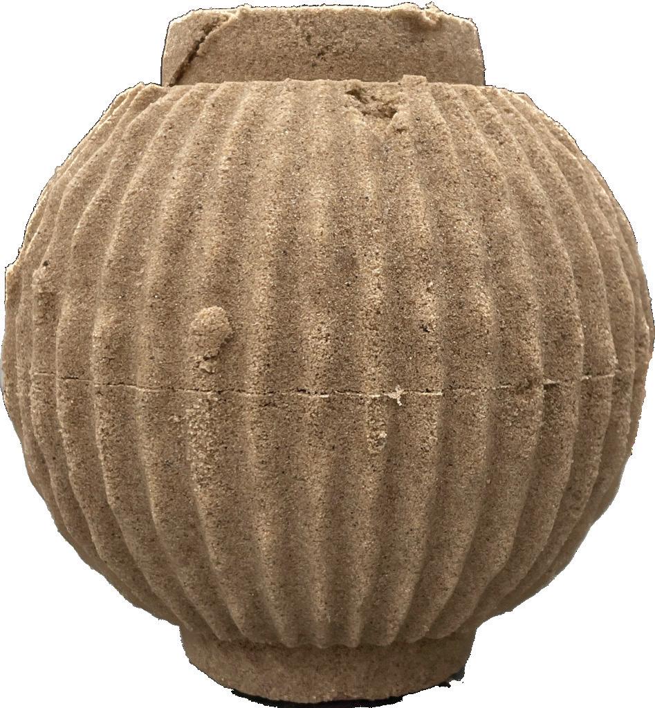
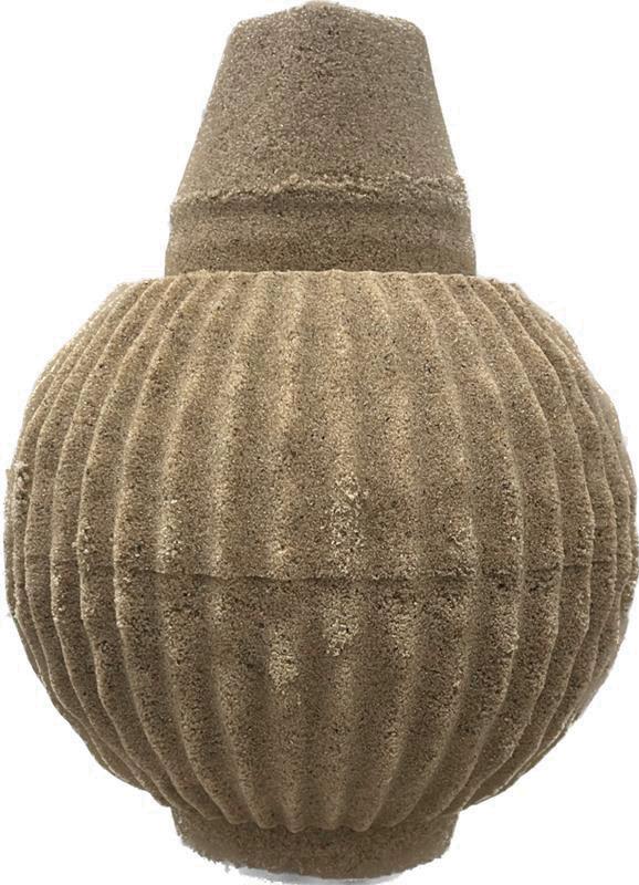
Sand Core Iteration 1 with Insufficient Locator Sand Core Iteration 5 with Redesigned Locator 1 2
10: Casting core iterations for initial and final locator design
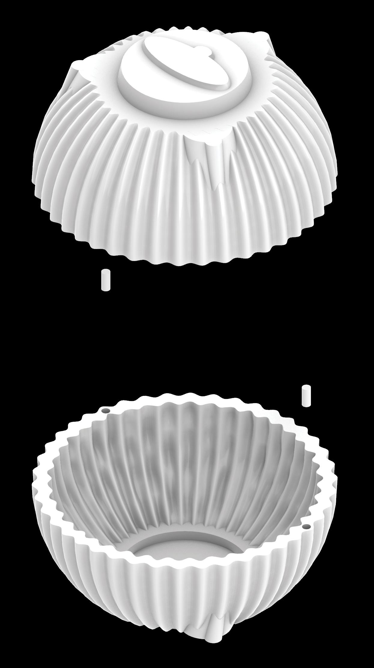
Core Box Iteration One
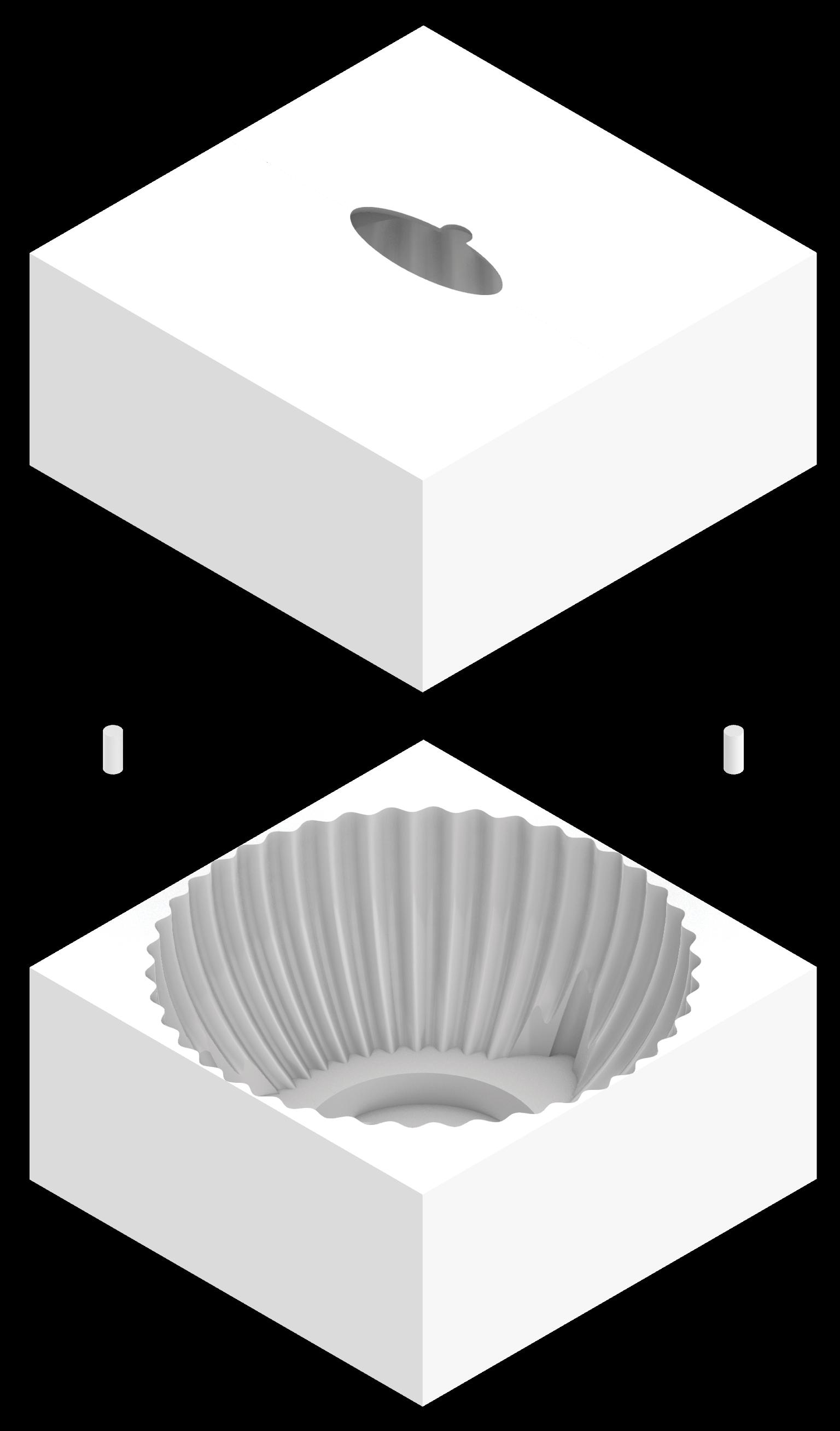
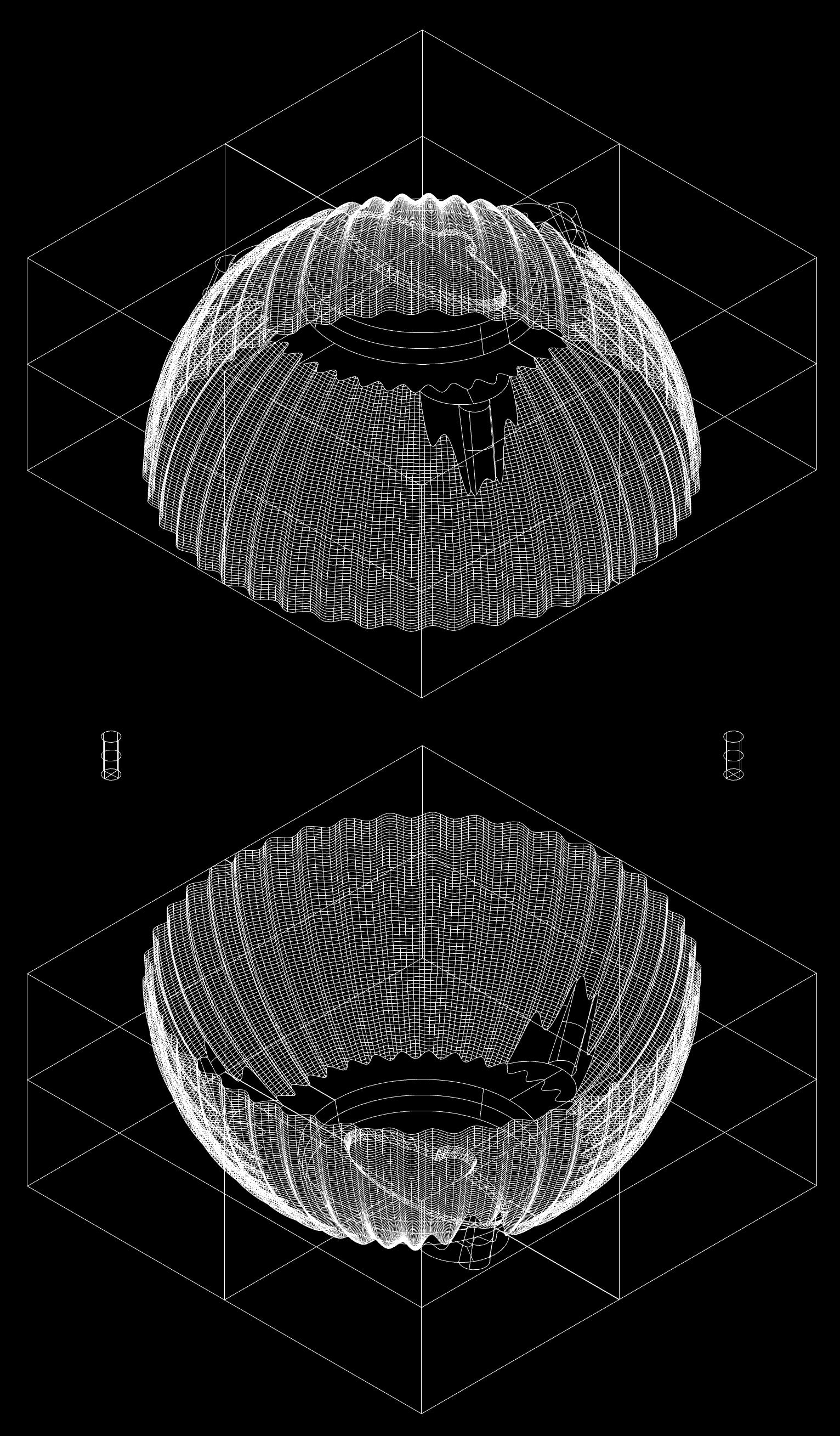
Figure 12: Core box iterations 1:2 Isometric
Core Box Iteration Two
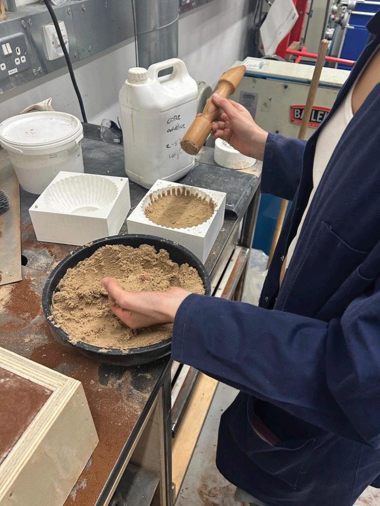
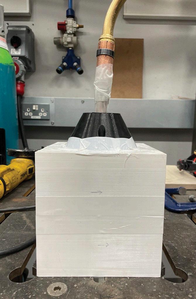
13: Photographs
Fine silica sand was used as the sand component of the core. Finer sands have the ability to produce smooth internal surfaces and precise detail, which is particularly important for capturing the internal articulations of the speaker casing (Deore et al., 2015). The sand was mixed with the core additive sodium silicate, with a ratio of 2-5% additive to the weight of the sand. The mixture was then cured using carbon dioxide gas, causing the sand mixture to harden and retain its shape (Weiss, 2018). Once the core had hardened, the core box was separated, leaving the sand core that could be placed inside the mould created by the pattern. A vertical orientation was chosen for the core to support its complex, hollow form and to ensure consistent gassing from the base upward, aiding in uniform hardening throughout. Unlike the green sand used in the sand casting process, sand cores are difficult to recycle due to the use of chemical binders that harden the sand. In the case of sodium silicate hardened cores, they cannot be recycled (Deore et al., 2015).
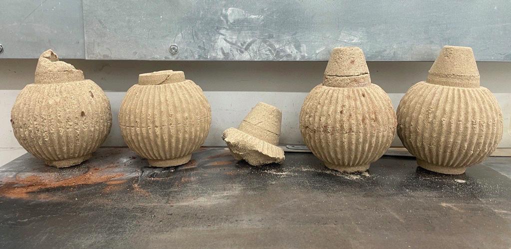
Many attempts were made to achieve a successful sand core. The greatest difficulty lay in enabling the carbon dioxide to permeate throughout the entirety of the core box and ensure the external articulations had hardened, as well as the internal volume of the core. Unsuccessful attempts left both interior and exterior sections soft and structurally weak, as seen in a number of the core iterations in Figure 13. To ensure consistent hardening, it was necessary to gain control of the gas flow throughout the core box. The first approach relied on simply exposing the entire core box to gas, which proved inefficient and time consuming, as the gas failed to reach internal cavities effectively. To address this, a through-hole was introduced in the core, allowing gas to travel more directly into the central volume. This was further refined by inserting a perforated metal tube, which improved gas distribution throughout the core. Additional adjustments were made to make the core box
airtight and better control the gas flow. To improve the gas flow, holes were drilled at the base of the core box, with tape being used to make the box airtight. As more gas was introduced to the core box, the tape was gradually removed, allowing the gas to escape through different gaps in a controlled manner. This encouraged the CO₂ to travel through the entire volume of the core, hardening the bottom and internal sections as it was forced outward. The drilled holes aided airflow but were small enough to be sealed as needed to control the process. The gassing duration also proved critical: while early attempts used around 5 minutes, more successful iterations extended to nearly 10 minutes, significantly improving core strength and consistency. These adaptations (as seen in Figure 13) ultimately allowed for even and reliable hardening, enabling the core to hold its form during casting.
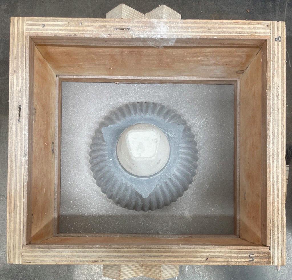
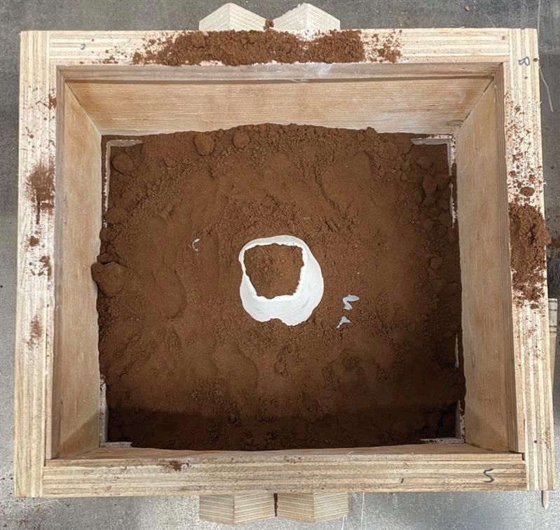
Once the pattern and sand core had been created, the mould was prepared using a green sand moulding method. The pattern was divided into two halves to align with the construction of the mould: the cope (top half) and the drag (bottom half). The flask (cope and drag) was filled with a compacted mixture of silica sand, bentonite clay, and water, a traditional green sand formulation. The combination of clay and the moisture content gives the sand its plasticity, allowing it to be packed tightly around the pattern to retain fine detail. Green sand is widely used in smaller batch production as it is cost-effective and almost infinitely recyclable, though it typically offers lower dimensional precision and surface finish compared to chemically bonded alternatives (Bralla, 2000).
Before packing, the sand mixture was evaluated tactilely, a technique developed through the observation of more knowledgeable casting practitioners. A mixture that was too wet would adhere to the pattern, while overly dry sand could lead to mould collapse. To ensure that the moulding process would be effective, numerous mould-making attempts were carried out prior to any casting, allowing for the development of essential skills and confidence in the stability of the mould under casting conditions. The sand was first sieved and then carefully rammed into the drag. To avoid the formation of layered, overly compacted sand, which can weaken the mould and hinder pattern removal, the ramming was performed with a lighter, more sporadic technique. Generous amounts of parting powder were applied between the pattern and the sand to aid clean separation. These early trials played a critical role in refining the process and establishing consistency before introducing molten metal.
A dual gate system method was used in the initial casting, with an entry point on either side of the mould. The first gate allows the flow of aluminium into the mould, and the second allows the pourer to assess when the mould has been fully filled with molten metal. Although the use of a riser was considered, it was omitted in this first attempt to assess whether it was strictly necessary. Gates and risers are critical elements in casting: gates direct molten metal into the mould cavity, while risers act as reservoirs to compensate for shrinkage as the metal cools. Proper placement ensures directional solidification and reduces the risk of voids or porosity during cooling (Bralla, 2000; Baddoo, 1996).
In the first casting attempt, the failure lay not in the moulding or gating system, but in the pouring setup. Insufficient clearance between the crucible and mould led to an awkward pouring angle. As a result, significant aluminium spillage occurred, a safety hazard, as the molten metal risked igniting the flask or surrounding materials. The pour was stopped, and the cope and drag were repositioned for better access. However, this movement caused the core to shift, leading to a partial internal collapse of the mould. Despite this, once the flask had been repositioned, the aluminium successfully filled much of the cavity, capturing the intricate form of both the pattern and the sand core, with the failure limited to the bottom of the cast.
For the subsequent casting, pours used the same gate system but with a reconfigured casting setup that allowed the pourer better access and control. This secondary casting attempt resulted in a complete casting. Although the external finish was not perfect, the articulations formed by the core were captured successfully. As the outer surface of the component was intended to be postprocessed through milling, the surface imperfections
Bottom half of the pattern
Flask placed over the bottom pattern
One half of the mould (drag)
Top half of the pattern
Flask placed over the top pattern
Assembled moulds (including core)
Casting through the gating system
Other half of the mould (cope)
The solidified casting
14: Schematic casting diagram adapted from Fundamentals of Aluminium Metallurgy (Lumley, 2010)
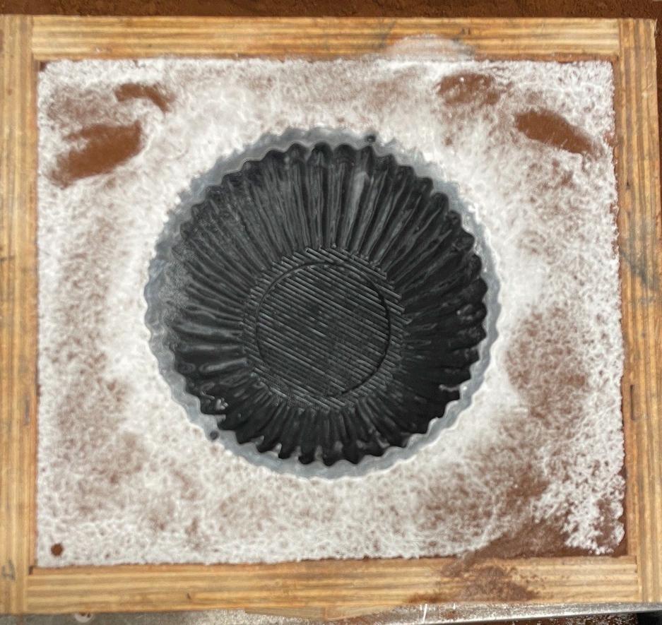
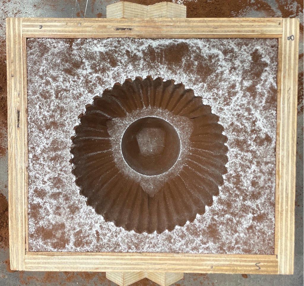
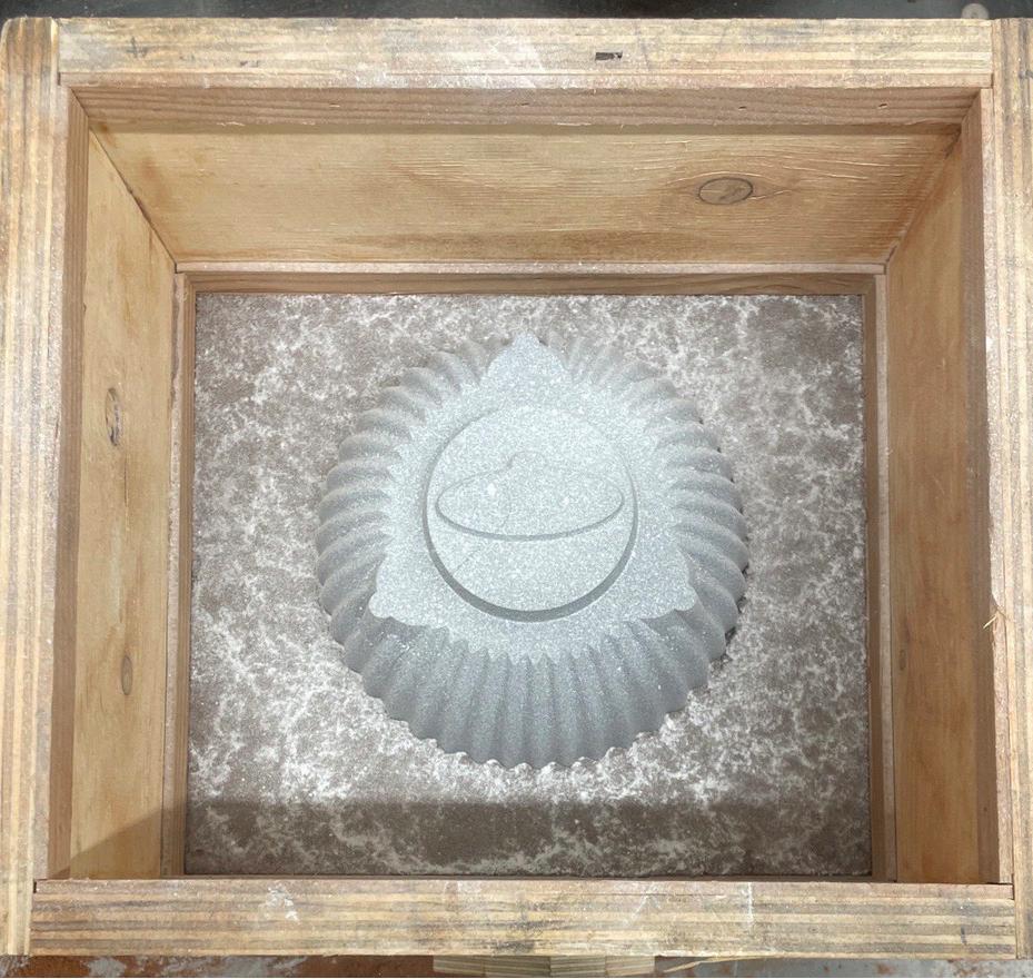
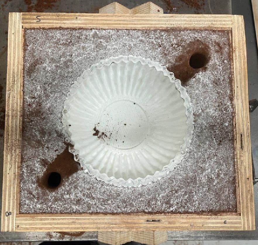
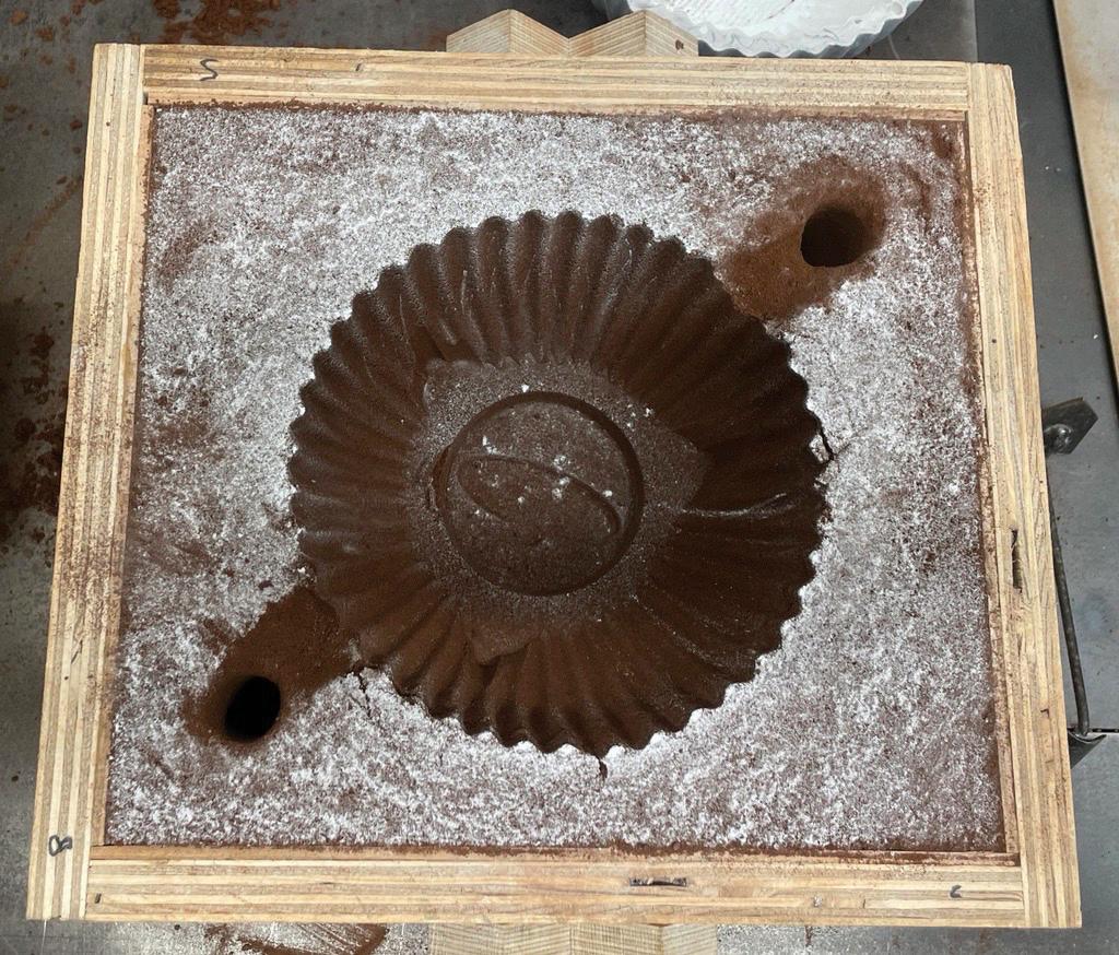
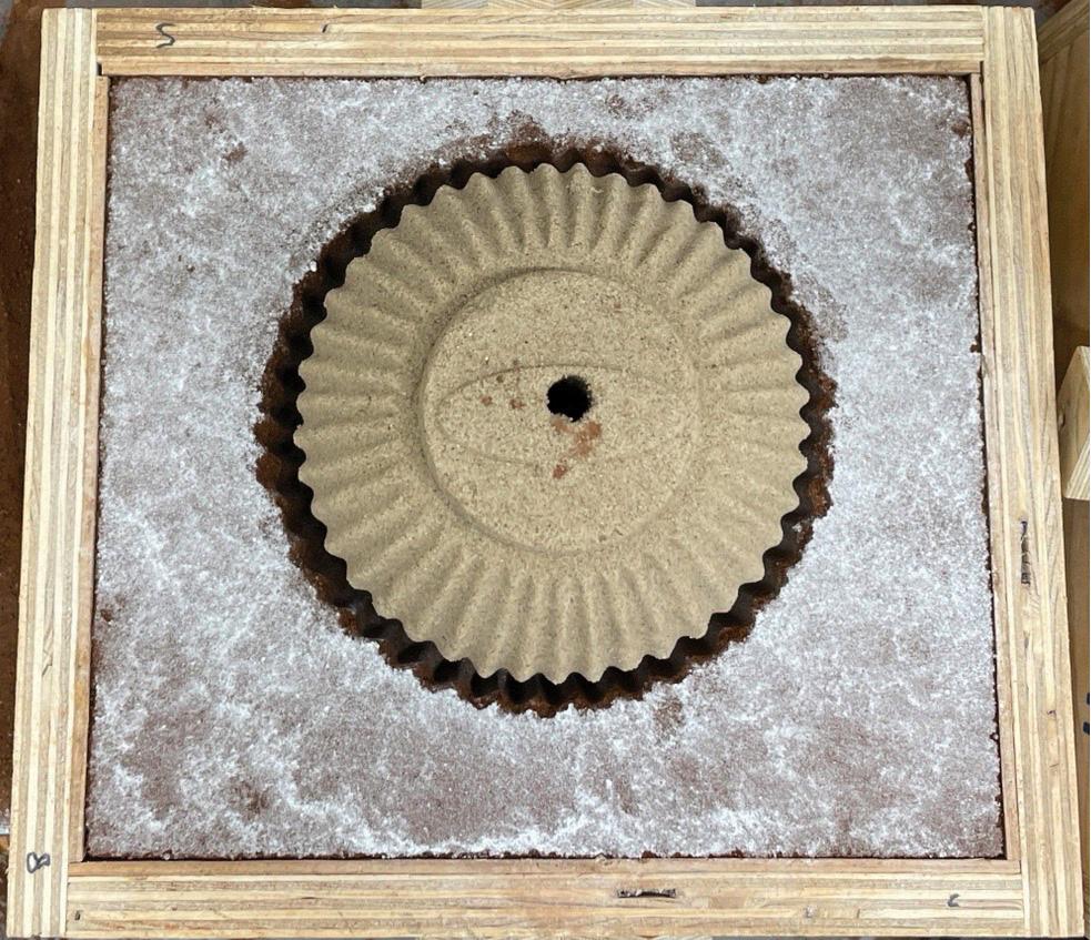
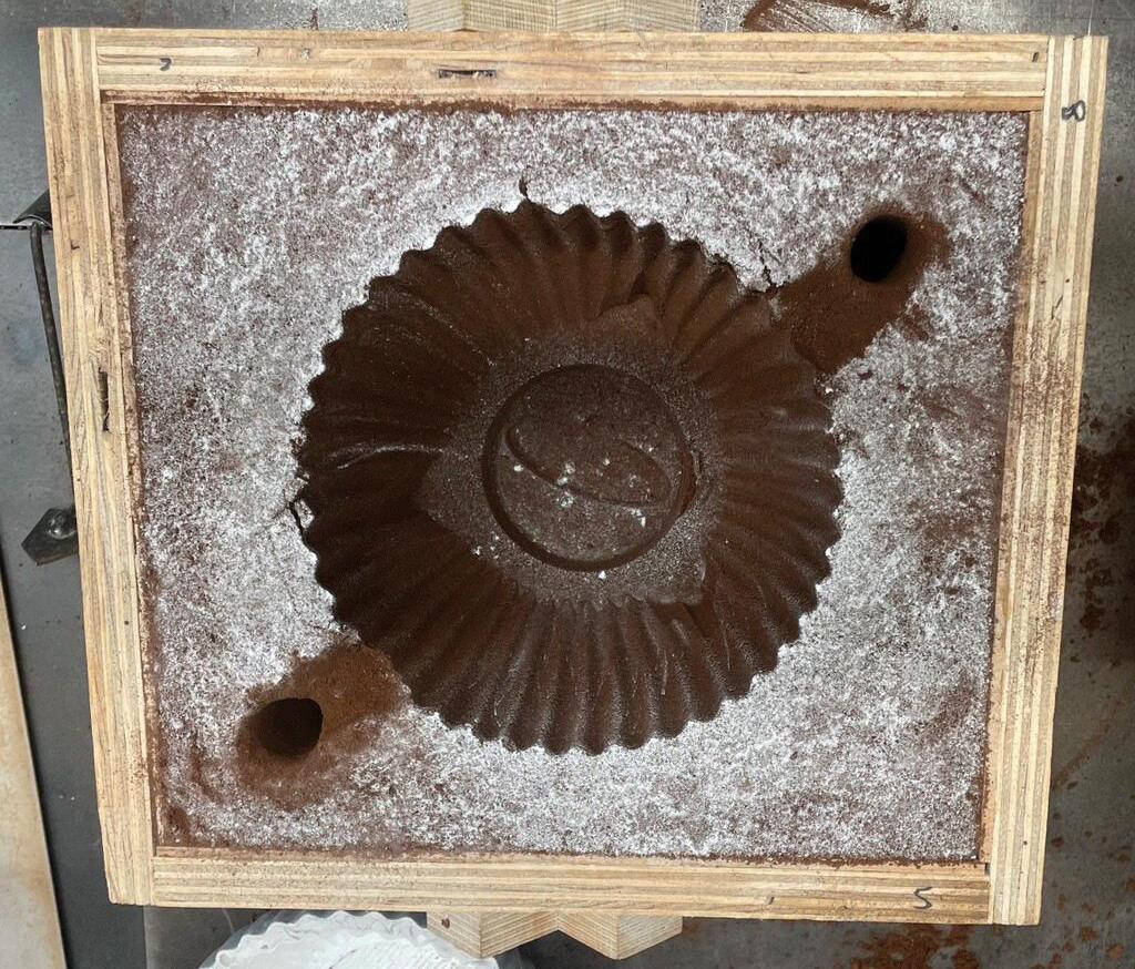
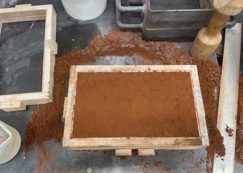
15: Photographs of the casting process (Amini, 2025)
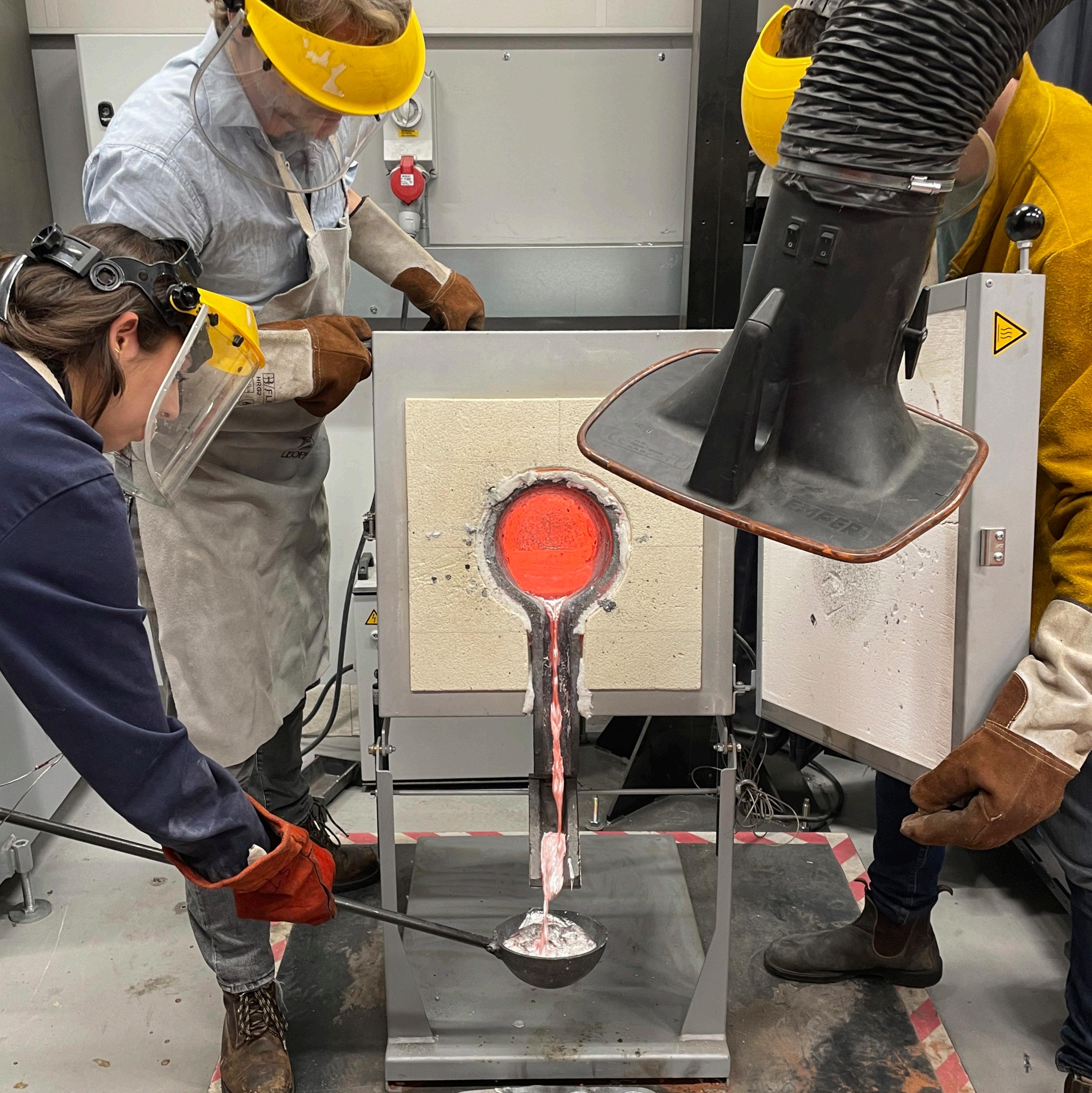
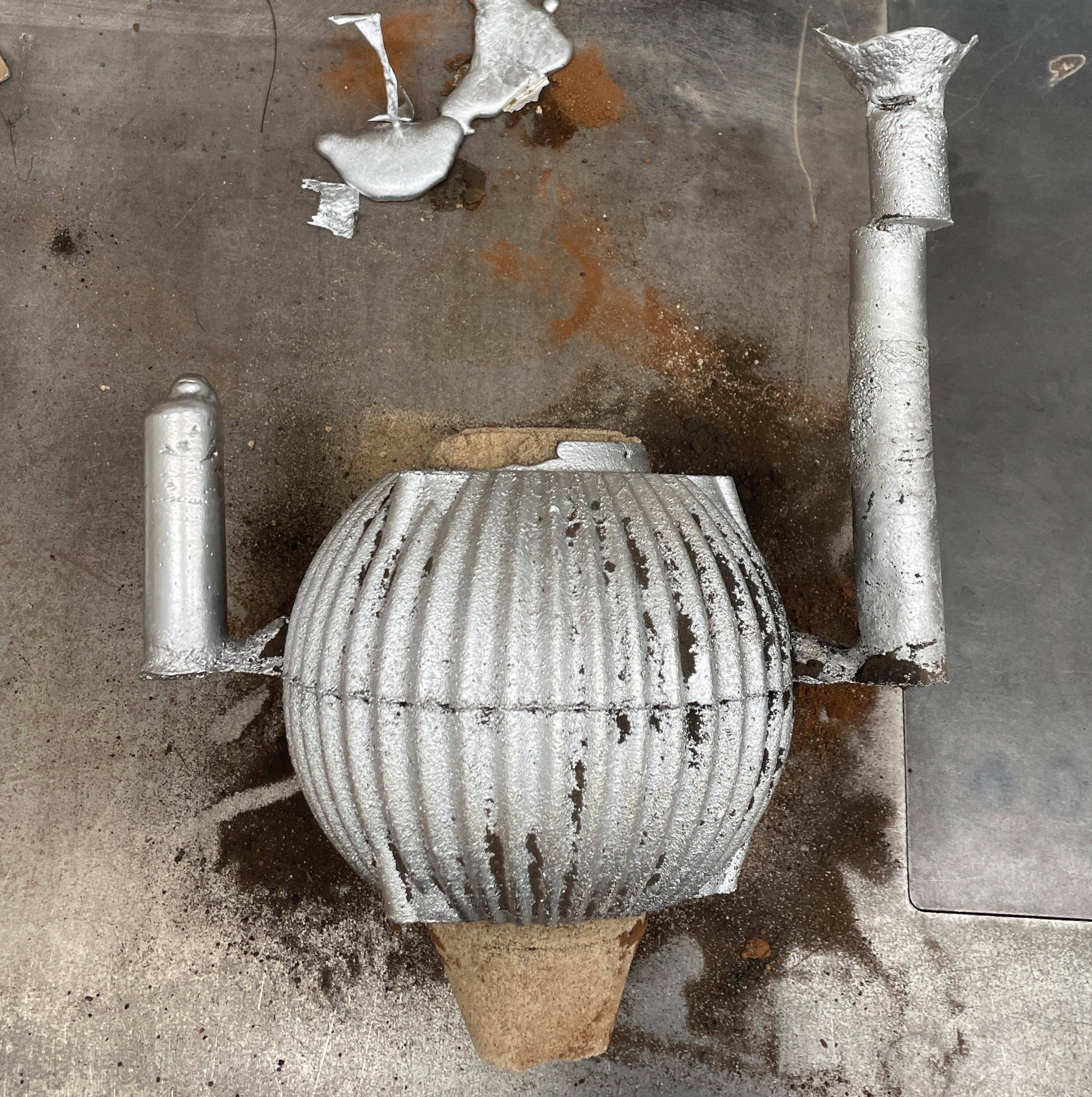
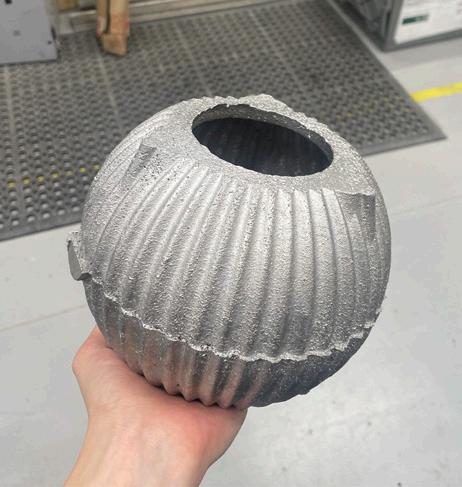
were not considered critical. Given the importance of the machined articulation points, initiating the machining process early was prioritised.
The casting process often requires many attempts to achieve a complete and successful result. The early success of this component can be largely attributed to the uniform wall thickness of the speaker’s geometry, which helped maintain a consistent flow of molten metal and reduced the likelihood of common casting defects such as hot tears, shrinkage voids, and uneven cooling. In addition, the fluid properties of the LM6 alloy used further supported the successful casting of the speaker casing (Aluminium Alloy Manufacturing & Recycling Association, 2018). While challenges were anticipated due to the complexity of the hollow form, the combination of a well-considered mould design, an appropriate gating system, consistent sand preparation, and a suitable alloy choice contributed to a result that, though not flawless, was both functionally and materially effective.
Once the component had been successfully cast and fettled using an angle grinder, the next step was to prepare it for CNC machining. A HAAS TM3 CNC milling machine was used, equipped with a 4th axis. CNC milling converts digital toolpaths into mechanical movements through the use of G-code. These paths guide a rotating tool across the surface of a material, shaping it into the intended form. Toolpaths are not limited to defining the tool’s route, but also dictate parameters such as the depth of cut, the feed rate, the spindle speed, and the step-over, all factors that influence the precision and quality of the final outcome.
Due to the inherent risks in machining a one-off aluminium casting, a 3D scan was conducted prior to machining. The machining process began by importing both the scanned geometry of the cast and the ideal CAD model into the workspace for comparison (Figure 21). The scan was used to define the stock, machine orientation, and the part’s origin. An appropriate machining strategy was then selected. Toolpaths for this project were created in Autodesk Fusion 360, using the software’s Manufacture workspace. The use of the 4th axis meant that a rotary parallel toolpath, which falls within multi-axis finishing passes, could be used. Two passes were run, the first a semi-finish with a step over of 2mm and a 0.5mm offset, the second, a final finish with a step over of 0.3mm. Toolpaths were then simulated to verify the operation and check for potential collisions. Once approved, the G-code was post-processed for the HAAS TM3 CNC machine.
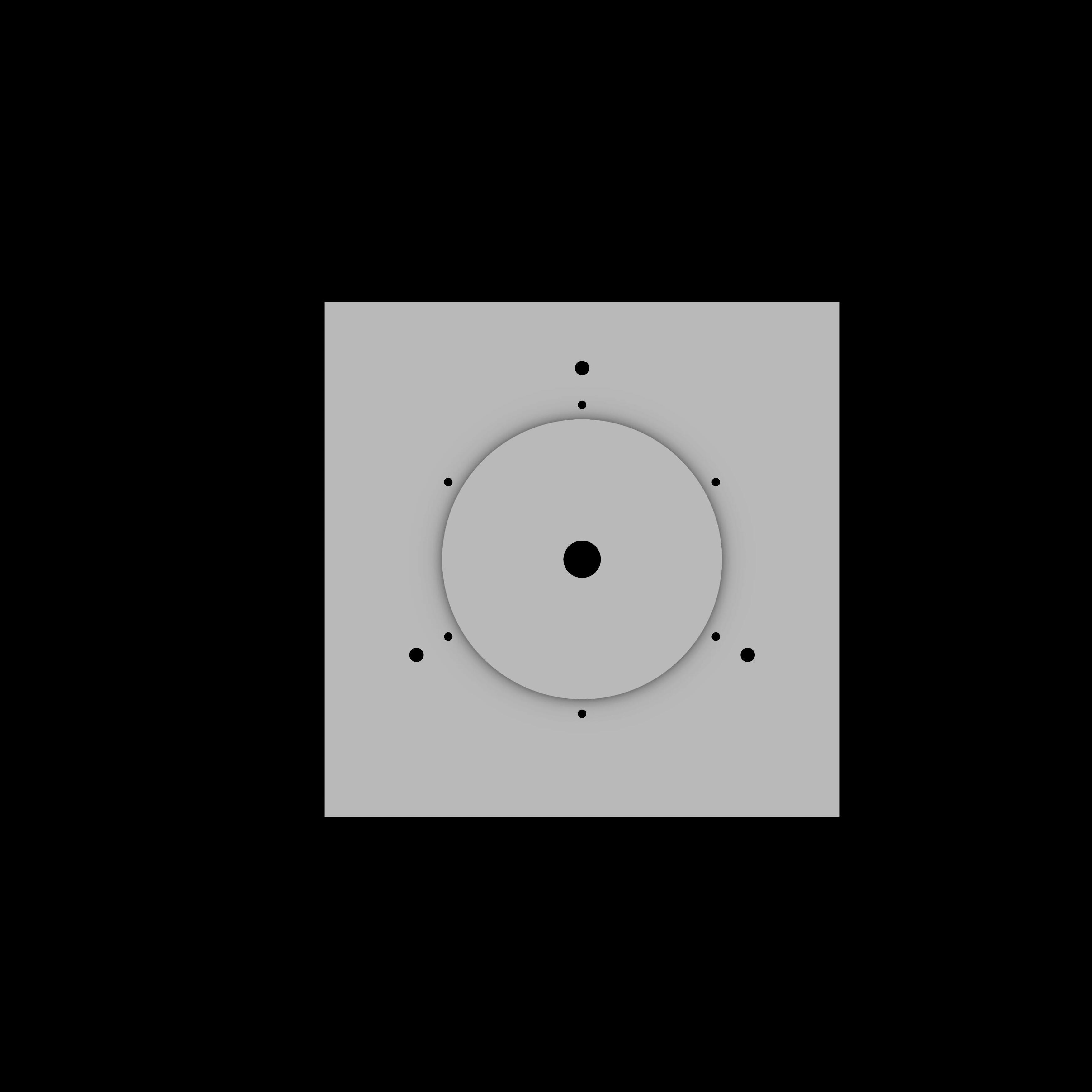
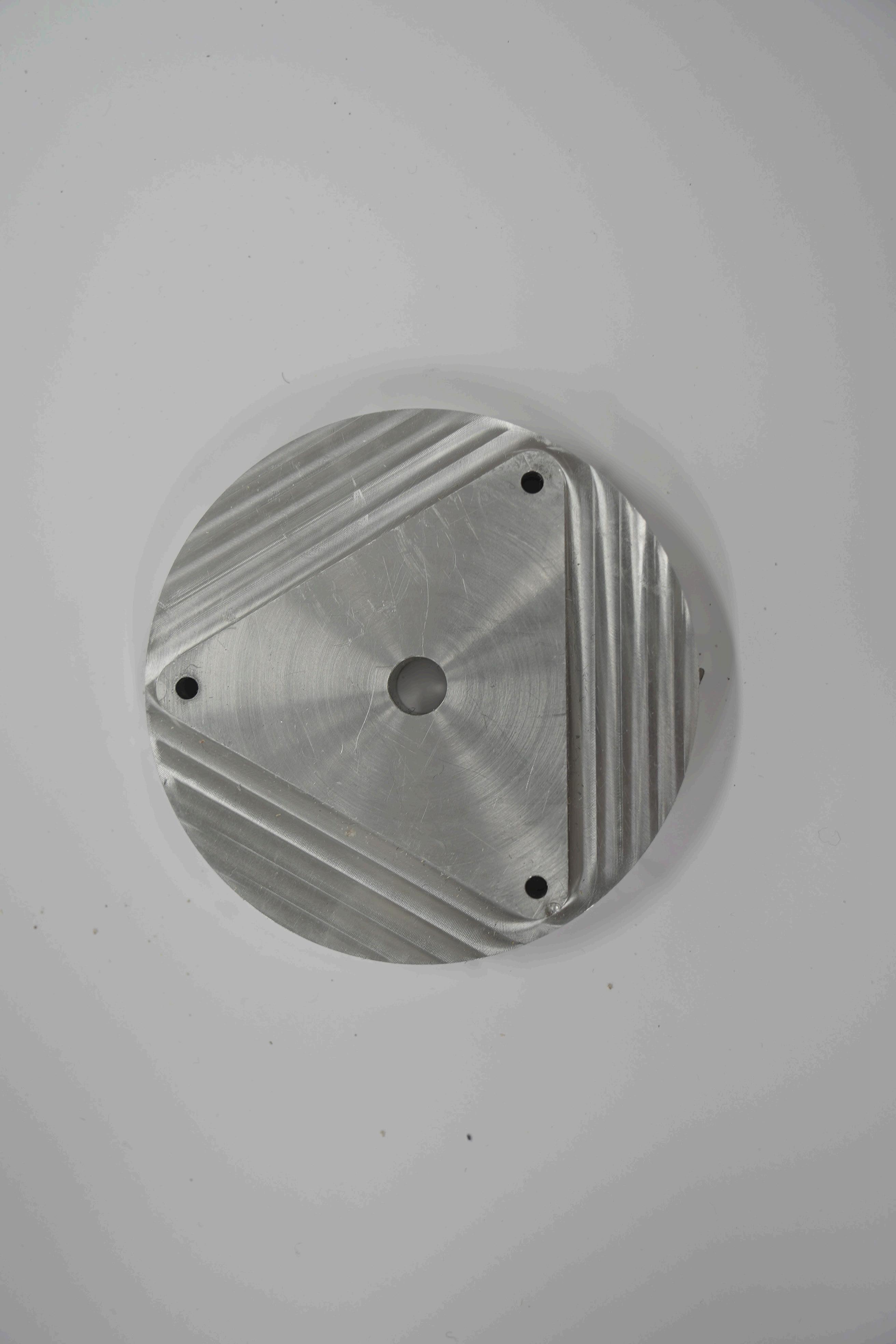
The first challenge was establishing a suitable work-holding solution. As the casting required holes on both the top and bottom surfaces for mounting and the subwoofer driver, it was logical to machine these first. These holes were then used to secure the part to a custom work-holding piece,
which also acted as a calibration reference for future 3D scanning. The initial fixture involved a central cylindrical locator on a plate, with a bolt that clamped against an internal plate, holding the casting in place by sandwiching it between two surfaces (Figure 19, 4). This method assumed that the opposing circular openings on either side of the casting were both central and parallel.
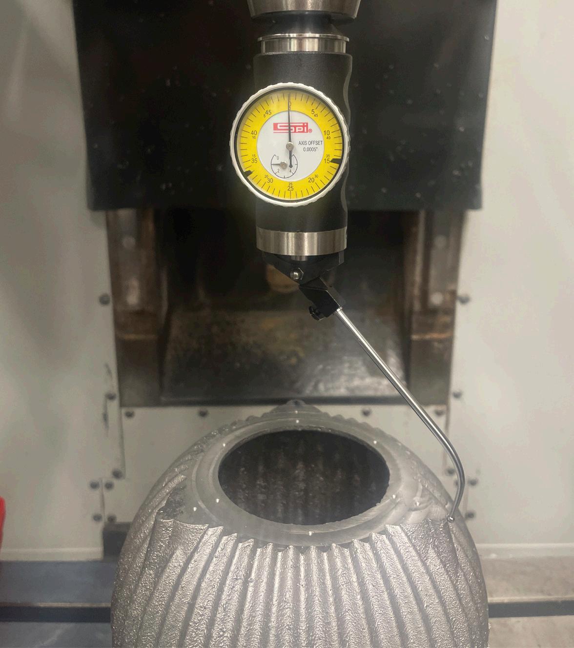
With the part mounted, the calibration and tool offset procedures were followed. Tools were loaded and zeroed using a height gauge, and the machine’s X, Y, and Z origins were set. After setup, a surfacing pass was performed to flatten the top face, followed by a test pass to machine the mounting holes. However, this revealed a critical issue: the holes were significantly misaligned, suggesting an error in either the model, the work-holding piece, or the CNC calibration (Figure 19, 1).
After verifying the model and the pattern, attention turned to the casting and work-holding solution. It was discovered that the base of the casting was not sitting flat on the workholding piece, causing the component to tilt and skew the top face. This tilt altered the effective surface orientation, misplacing the toolpath. To address this, a process of shimming was used, placing thin metal sheets at key points to level the casting (Figure 19, 2). Although this marginally improved alignment, the holes were still not correctly positioned.
A deeper investigation of the 3D scan revealed that the openings, initially assumed to be symmetrical, were not. As a result, the original work-holding piece design was deemed unsuitable. The cylindrical locator was removed, and instead, a dial gauge was used to identify the high points (Figure 19, 3). By manually identifying the three highest points on the casting surface, a more accurate centre and plane could be established. This adjustment
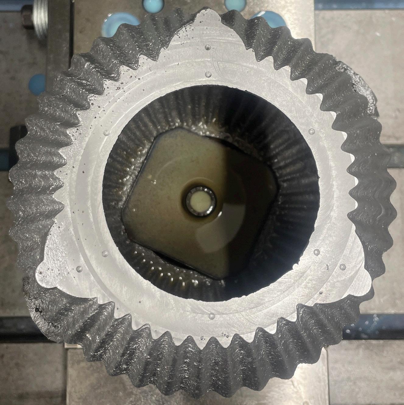
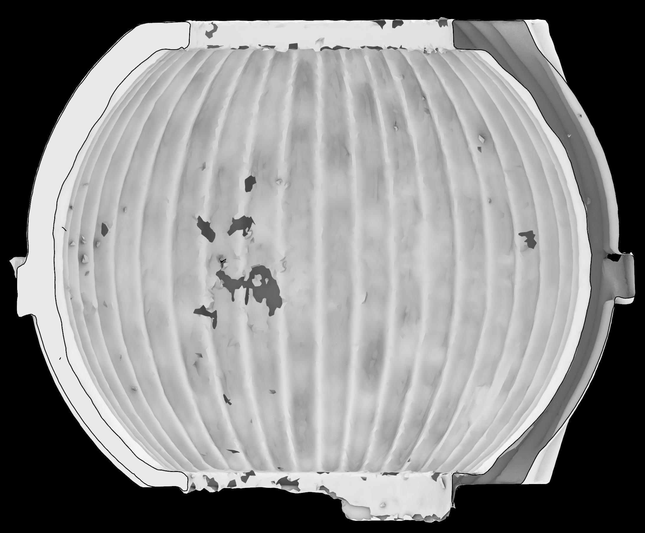
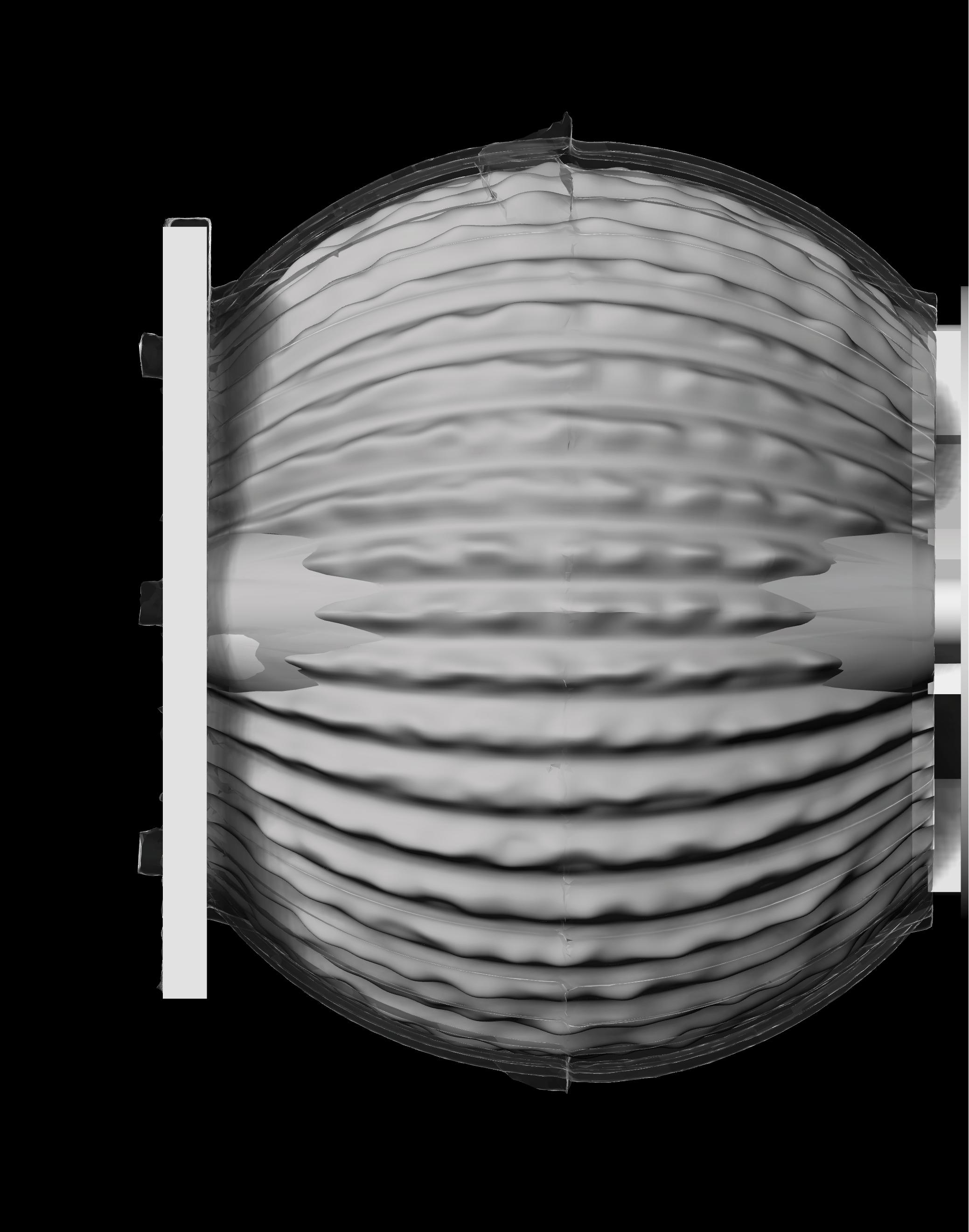
21: CNC machining setup showing casting against the idealised geometry
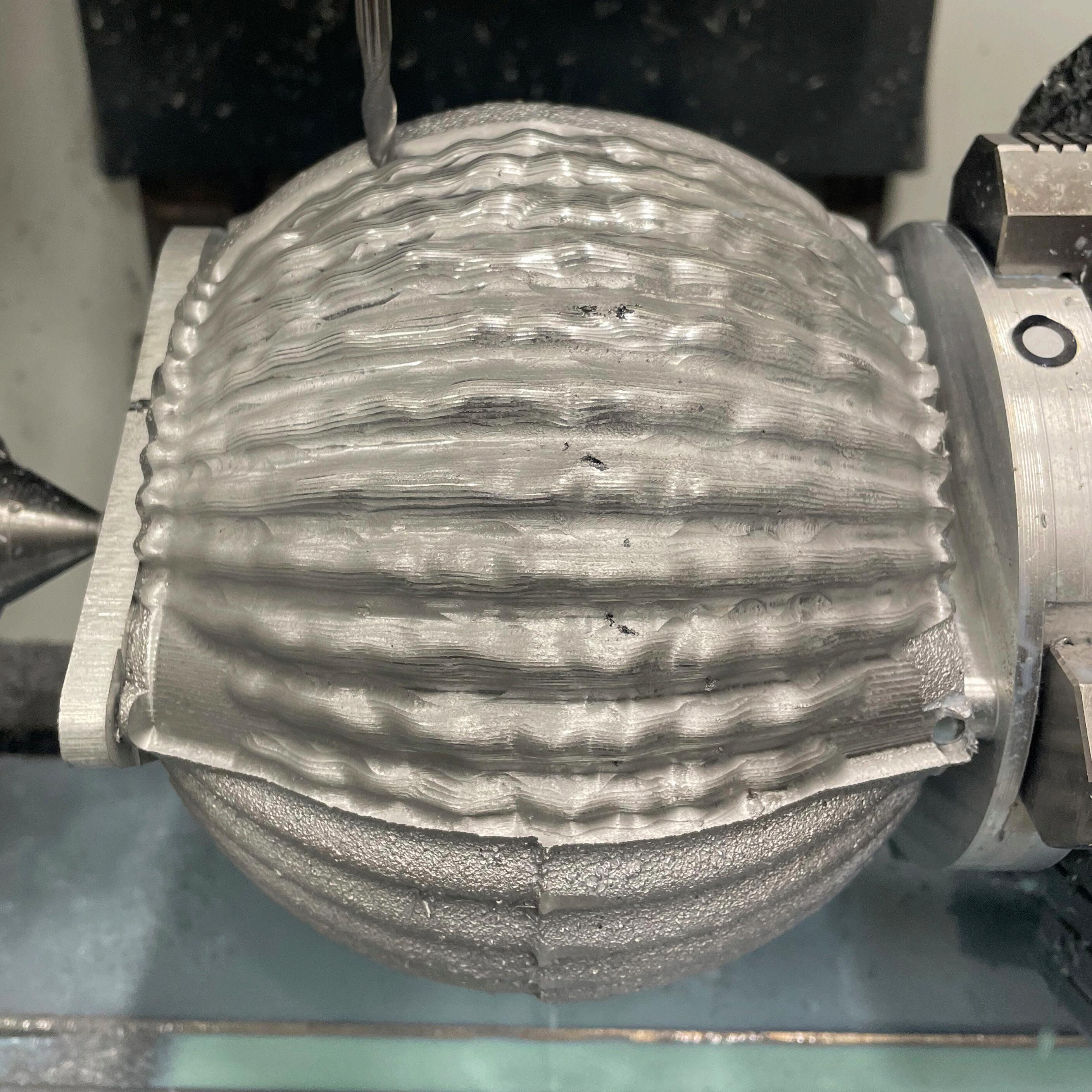
allowed for proper alignment, and subsequent hole machining produced correctly positioned results.
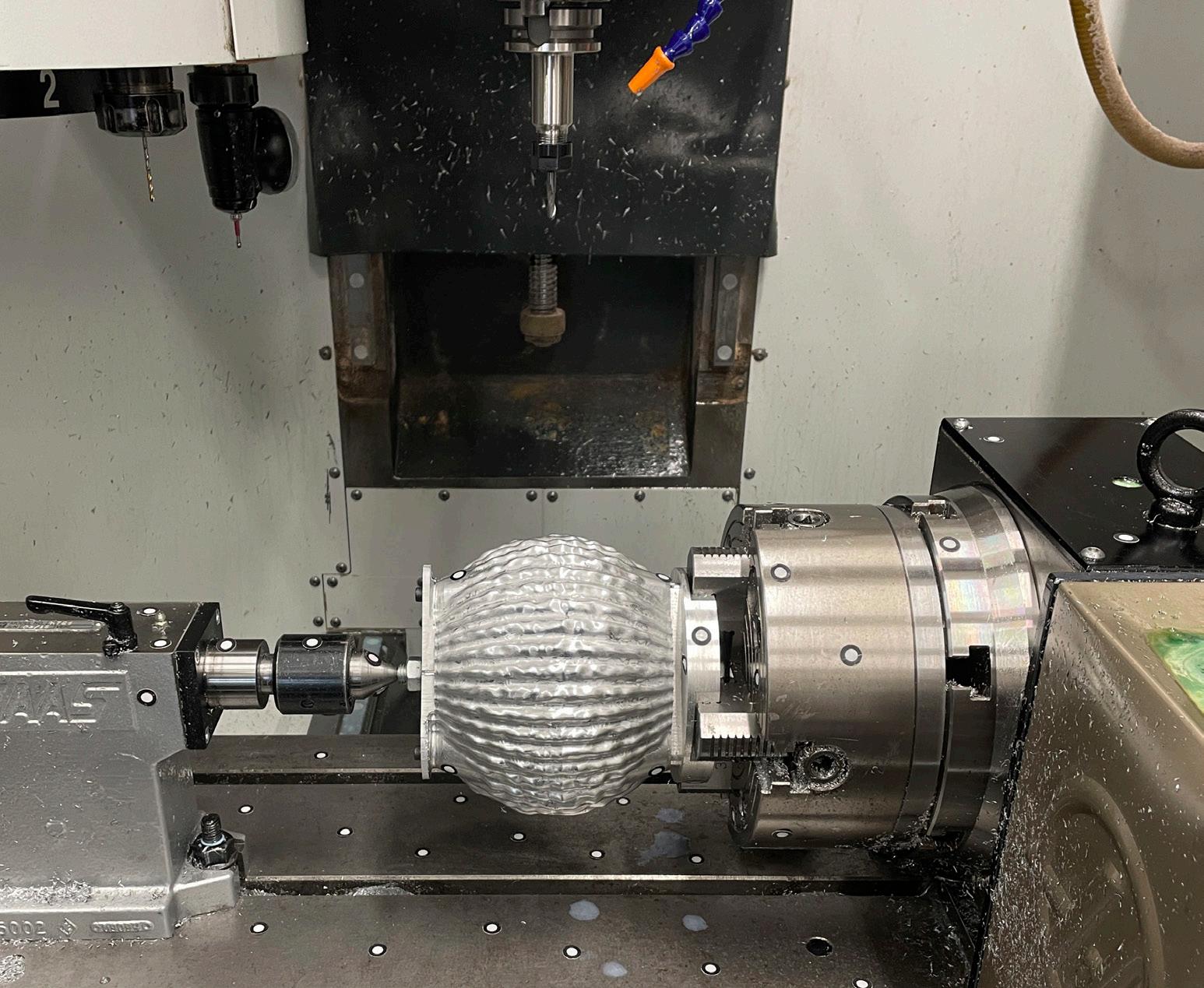
With the revised work holding in place, holes were machined on one side and then the other, using two separate fixtures. The part was then mounted on the CNC’s rotary axis, allowing the tool to reach all around the articulated geometry. After this, the two-pass strategy could be enacted: the first pass removed bulk material with a coarse step-over, and the second, a finishing pass, used finer steps to improve surface quality. While the process was time consuming, it produced clean, accurate articulations that respected the original design intent. The experience highlighted the importance of metrology and adaptability in working with non-uniform cast parts, particularly in a research led design context where no two outcomes are guaranteed to be the same.
This chapter critically evaluates the outcome of the articulated speaker, focusing on its resemblance to the CAD model, dimensional accuracy and geometric form. Dimensional accuracy and geometric form, whilst often connected, assess distinct aspects of a manufactured object. Dimensional accuracy refers to how closely the final product matches the defined measurements of the 3D CAD model, while geometric form refers to the overall shape and spatial relationships of the object. A component may fall within acceptable dimensional tolerances yet deviate in form due to warping, misalignment, or surface irregularities, each of which can influence both the functional and aesthetic performance of the component.
In assessing the casting and machining processes undertaken in this project, this chapter identifies a range of material and process based defects. The evaluation draws upon both qualitative methods, such as visual and tactile inspection, and quantitative analysis using 3D scanning
and digital deviation mapping. Together, these approaches provide a holistic understanding of the speaker’s fabrication outcome. The findings not only reveal the strengths and limitations of the current manufacturing process but also show where improvements could be made, as well as what specification and tolerance controls could be introduced for future iterations. By understanding where and why the deviations occurred, future designs can be better optimised for manufacturability, reducing error and strengthening the relationship between the design intent and the physical outcome.
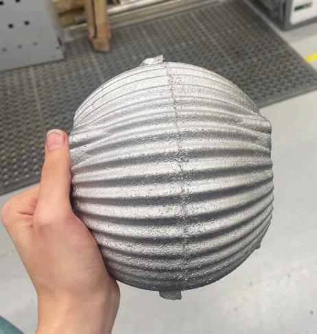
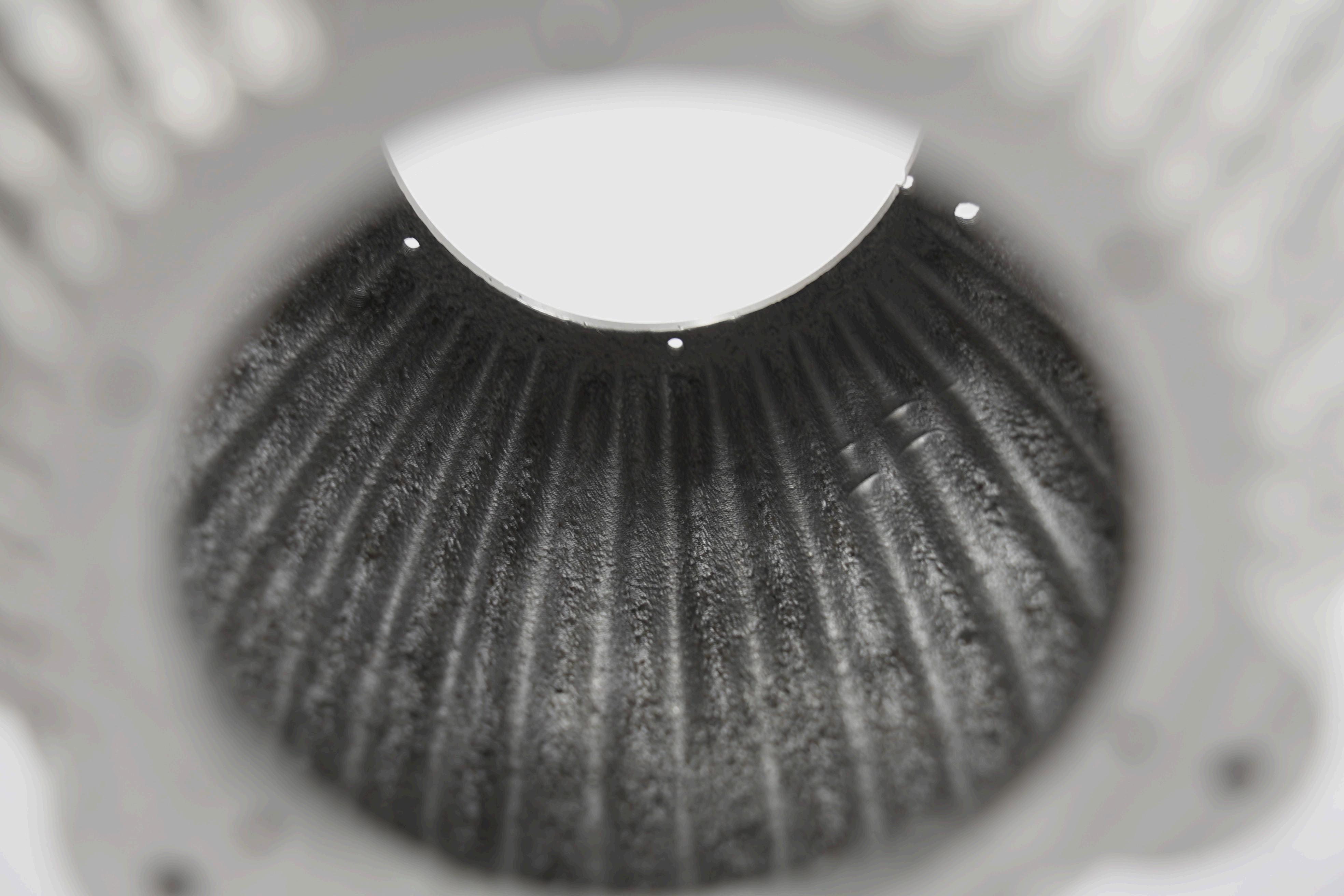
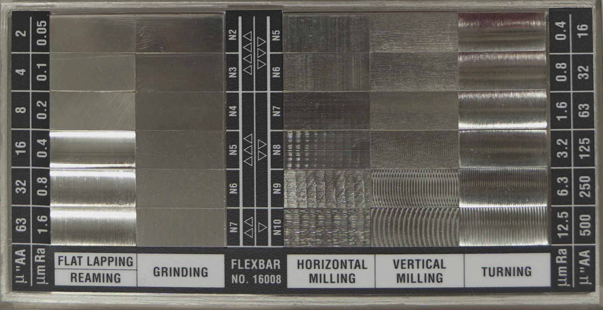
The finish of a ferrous green sand cast normally lies between 560 and 900 RMS (Root Mean Square), as seen in Figure 24. As a core was used for the casting, the finish of the internal and external surfaces differ, this can be seen in Figure 25. The surface finishes of both the initial and final casting are fairly similar, with both falling into the 560RMS category when evaluated using the ‘C9 Micro finish comparator surface finish scale’. The finish for the external surface is dictated by the mould making practices,
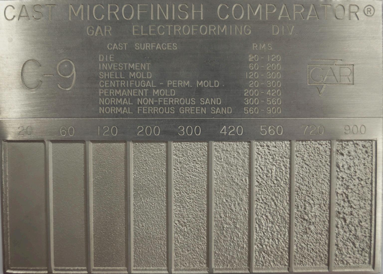
Figure 24: C9 Micro finish comparator surface finish scale
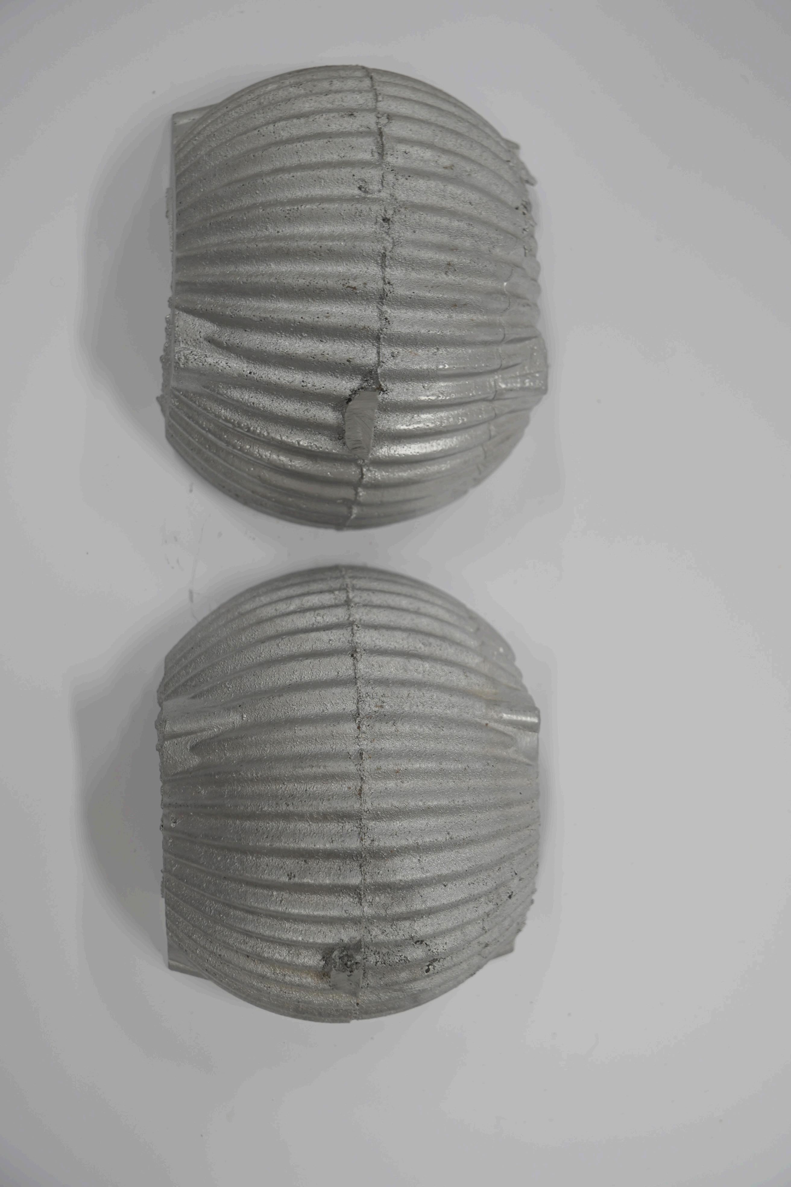
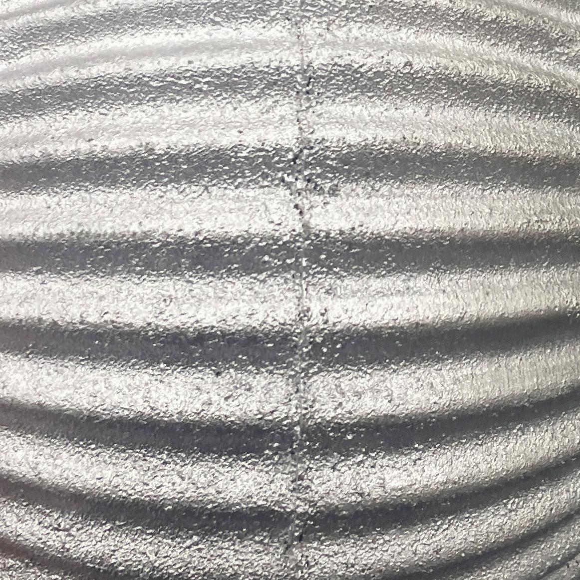
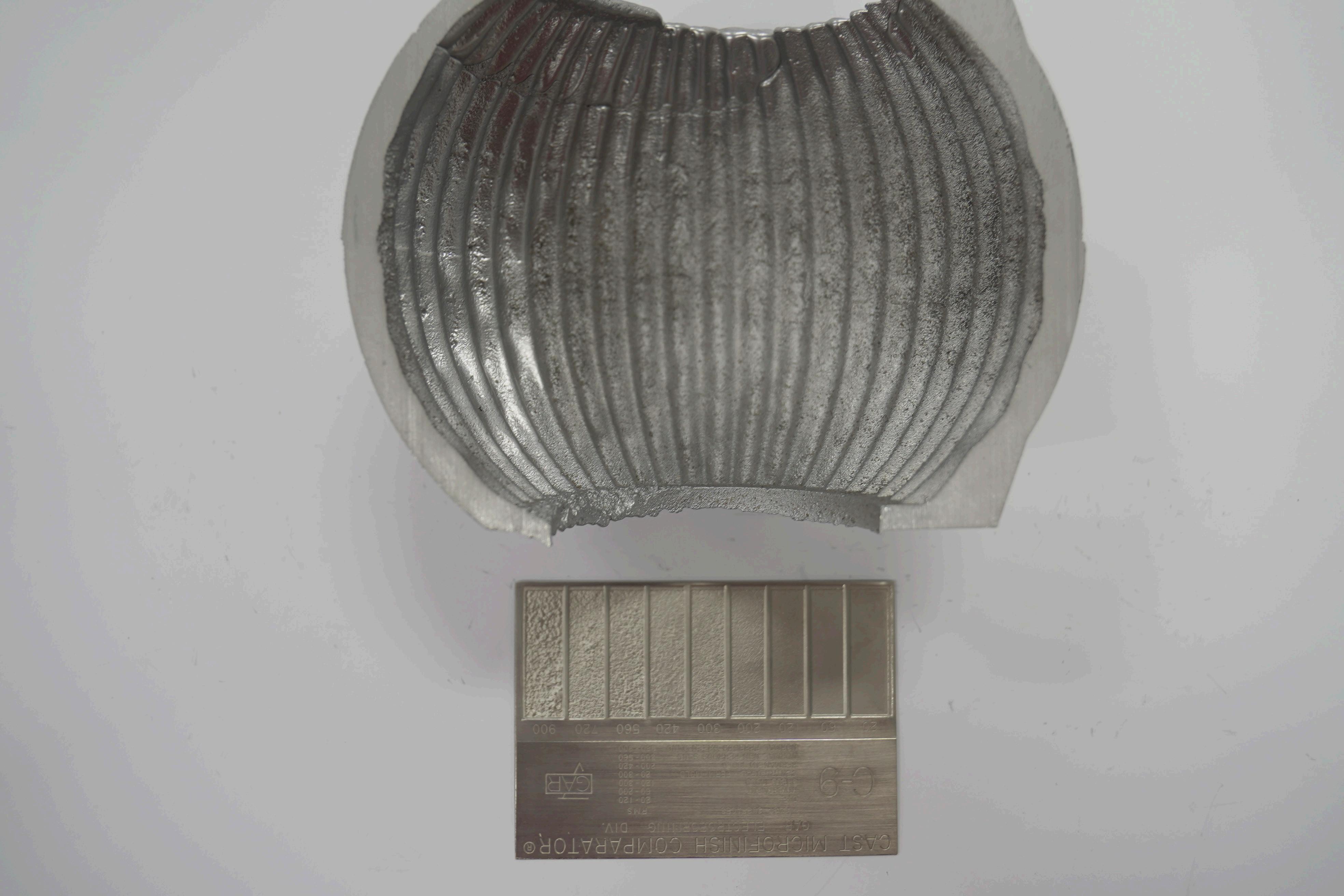
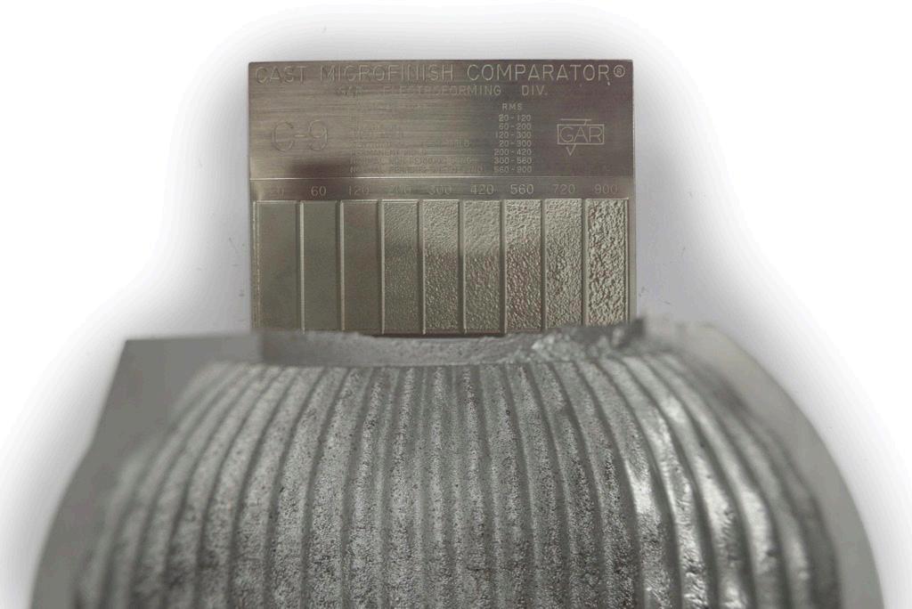
26: Comparing a section of the failed casting against the C9 Micro finish comparator surface finish scale
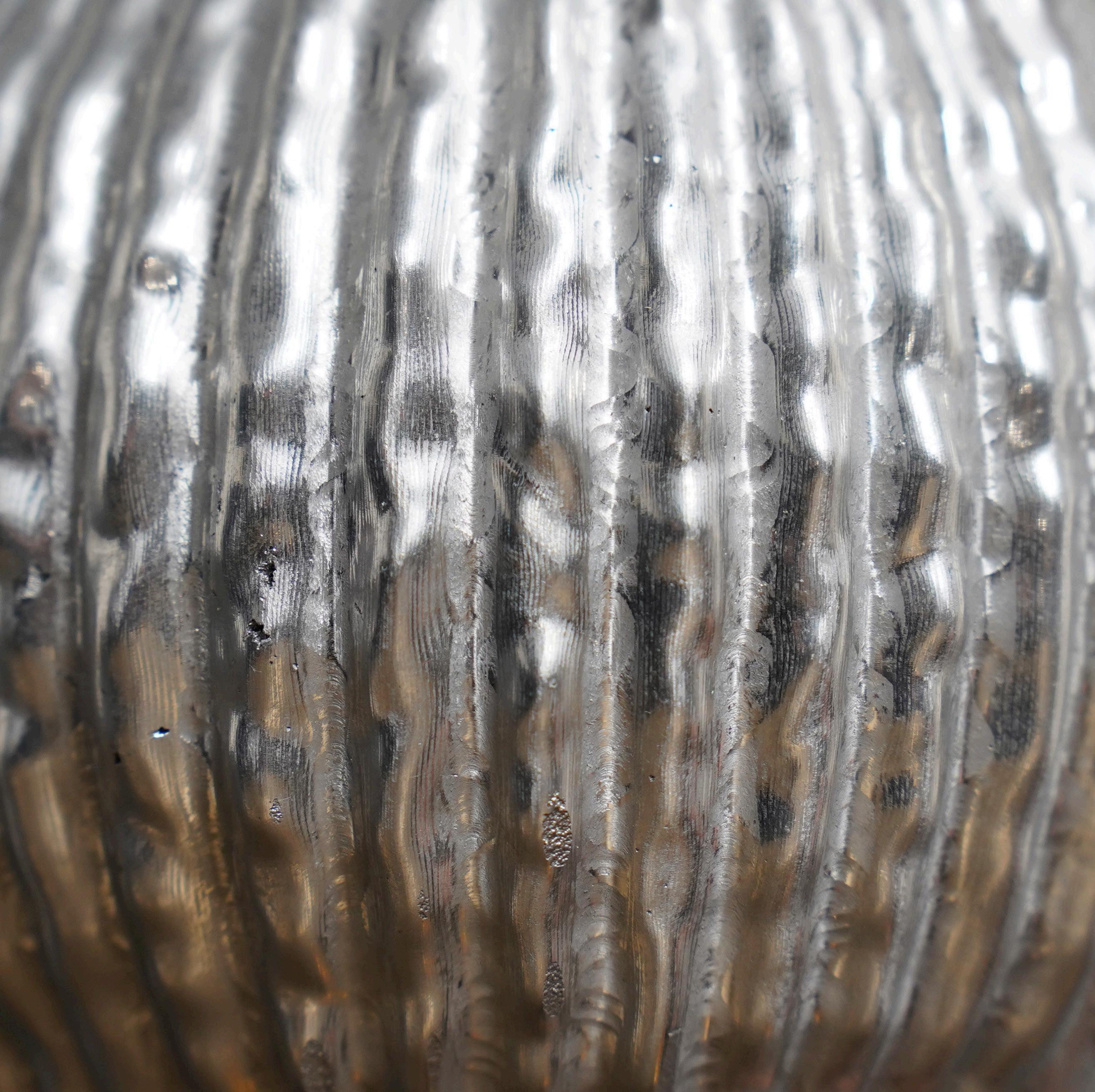
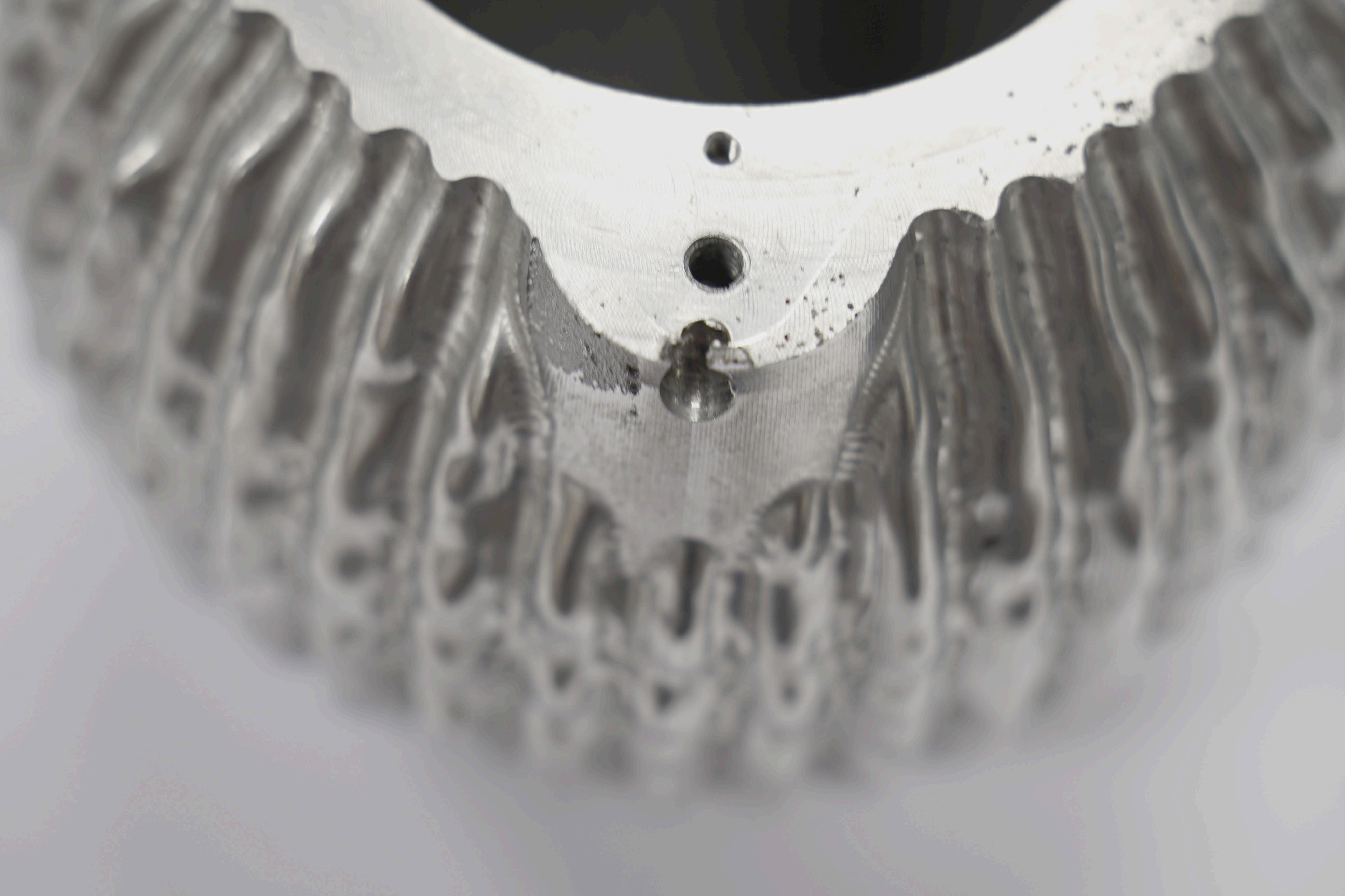
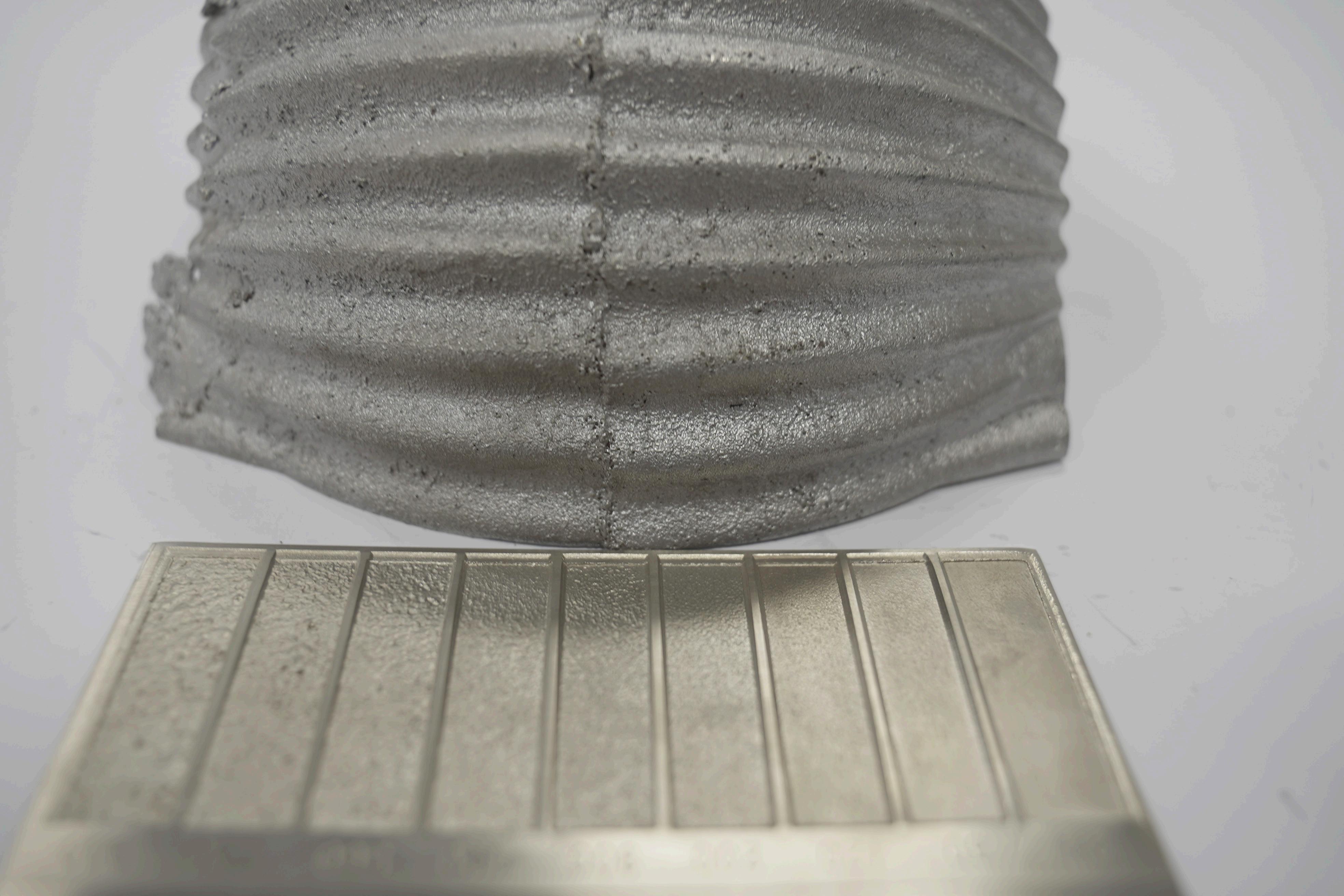
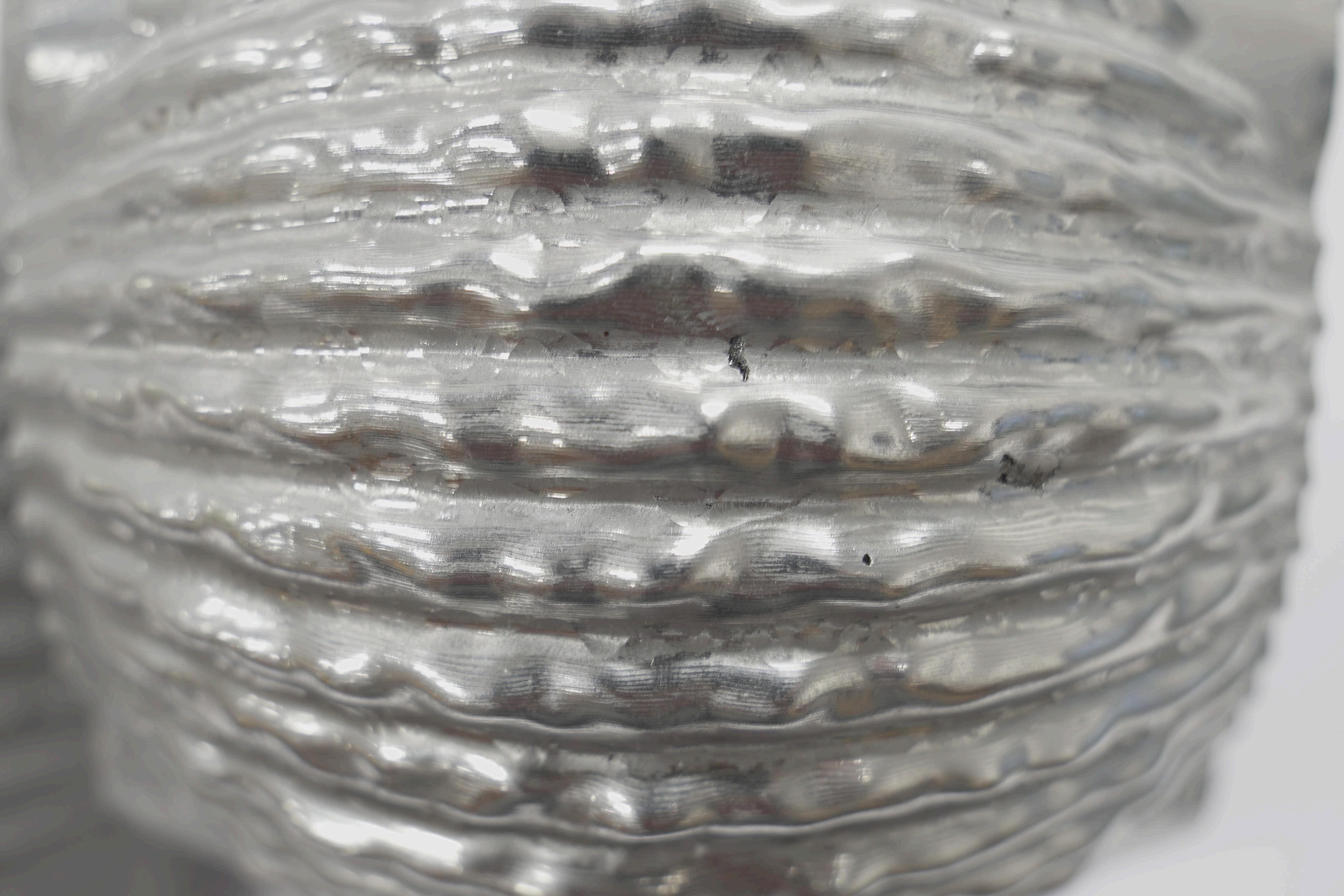
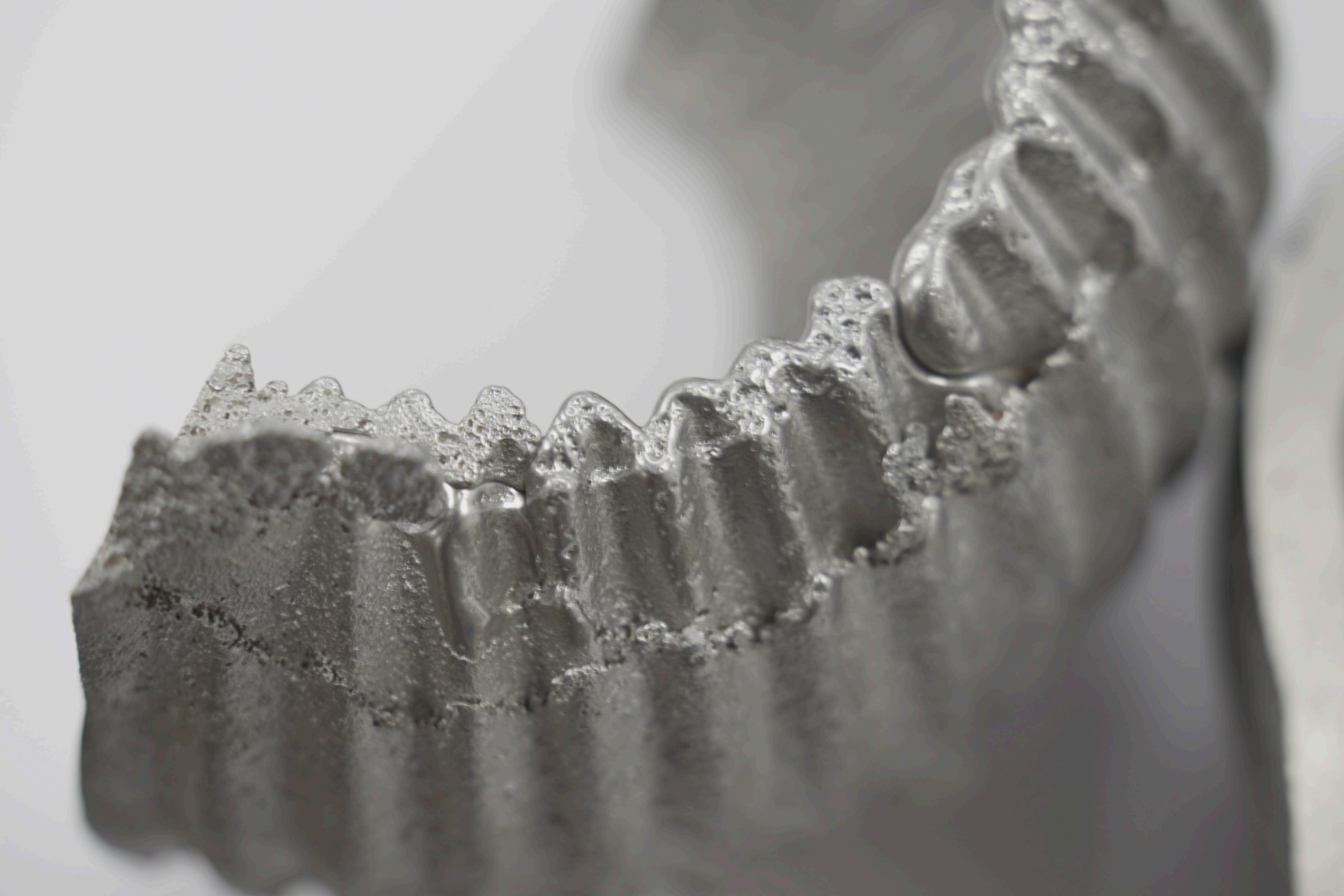
ensuring that sand is well compacted and the mould retains the integrity of the pattern is vital. A relatively good finish was achieved for the external surface, and this was likely due to the initial moulding attempts carried out prior to casting.
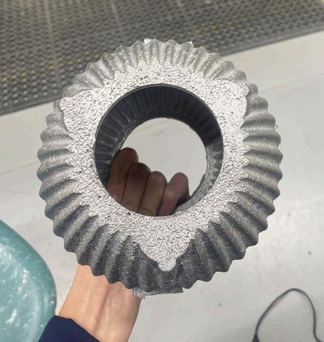
The internal surfaces both have a slightly worse surface finish (Figure 25), falling closer to 900RMS, with the initial casting appearing to have a better finish than the final casting. The middle areas of both the internal surfaces of the castings seem to have the lowest quality finish. This could be attributed to the sand core not being fully permeated with carbon dioxide, leaving the middle edges unsolidified and prone to shifting, causing a poorer surface finish. Although similar core-making practices were used for both the initial and final casting, it is possible that carbon dioxide permeated more thoroughly in the initial core compared to the final one, leading to a better surface finish.
Aluminium casting is susceptible to various defects that can compromise both the performance and finish of the component. Two notable issues were observed in both castings: gas porosity and inclusion defects. Both of these defects extended deep enough into the casting to remain visible even after machining. Gas porosity typically results from gases, such as hydrogen dissolved in the molten metal, which form voids during solidification. This can be mitigated through degassing procedures prior to pouring, as well as by improving mould permeability and reducing turbulence in the metal flow (Bralla, 2000). Inclusion defects are introduced when impurities, or nonmetallic particles like sand, become trapped in the casting. These can be reduced by skimming the melt, using flux treatments, and ensuring a smooth, controlled pour, in addition to good mould making practice (Aluminium Casting
Alloys, 2018). In future iterations, the sand core could have been exposed to carbon dioxide for longer to ensure the core had completely cured and no sand would become loose during the casting process, a factor that could have led to a greater number of inclusions.
In the final casting used for milling, pattern misalignment can be clearly observed. Pattern misalignment in casting occurs when the two halves of the mould, the cope and the drag, do not align correctly, resulting in features that are visibly skewed or offset. In this case, the misalignment likely resulted from a lack of precise registration between the pattern halves or slight shifting during the ramming process. Small discrepancies can lead to noticeable errors in the final casting. Additionally, uneven compaction or sand degradation at the parting line can cause one half of the mould to sit at an angle. To prevent this, care should be taken to ensure the mould halves are properly seated and evenly compacted during preparation. The wooden dowels used to align the pattern could be replaced with more secure alignment features to aid with future moulds.
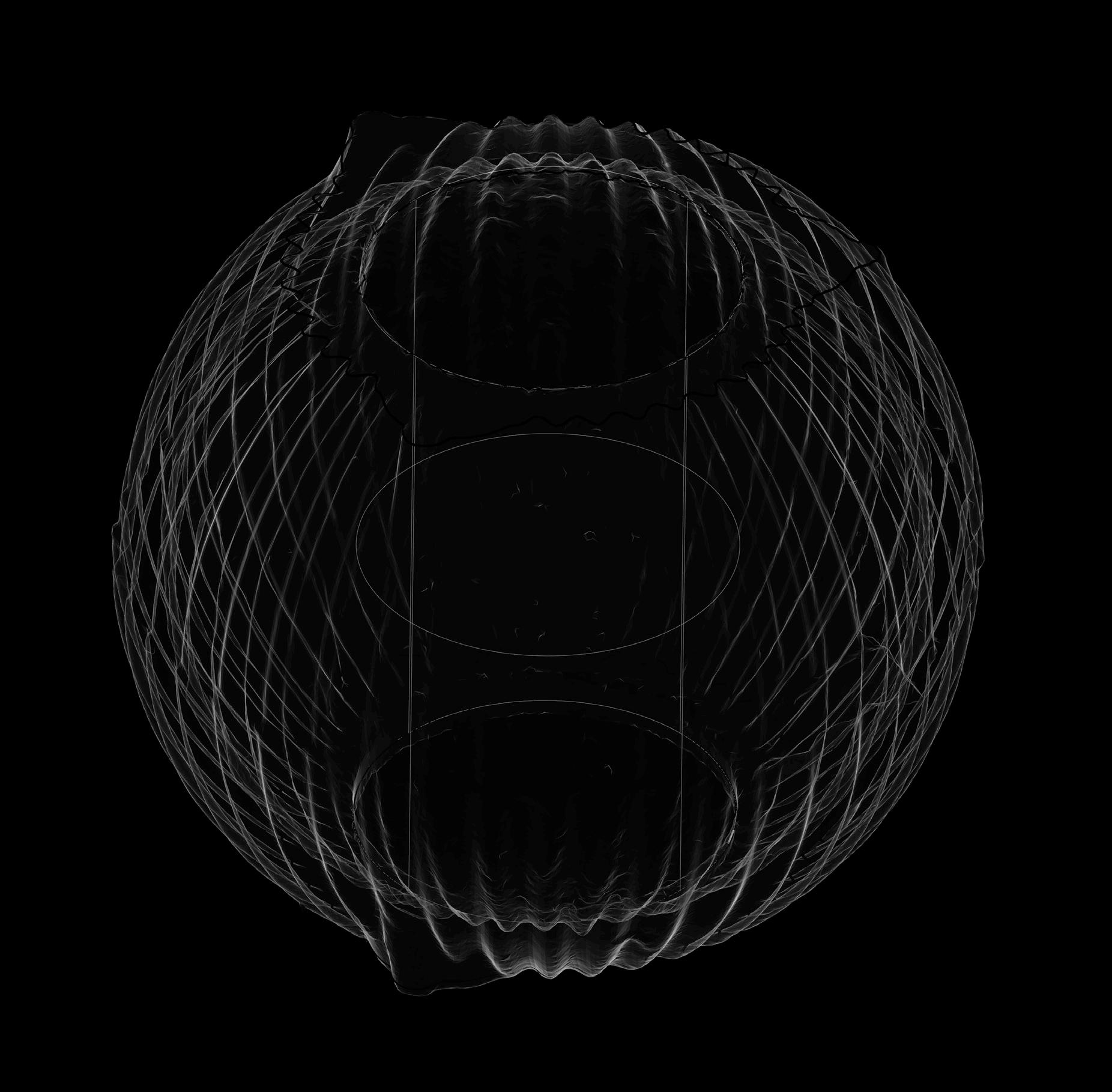
The misalignment of the holes on either side of the casting was the cause of significant problems in the machining process. When conferring with the 3D scan of the casting, the misalignment was caused by the core entering the mould at an angle of 0.868°, resulting in a 1.961mm offset between the holes. This angular displacement meant the openings were not symmetrical, complicating work holding and alignment on the CNC machine.
The method for placing the core had previously been to carefully drop it into the mould using the locator for
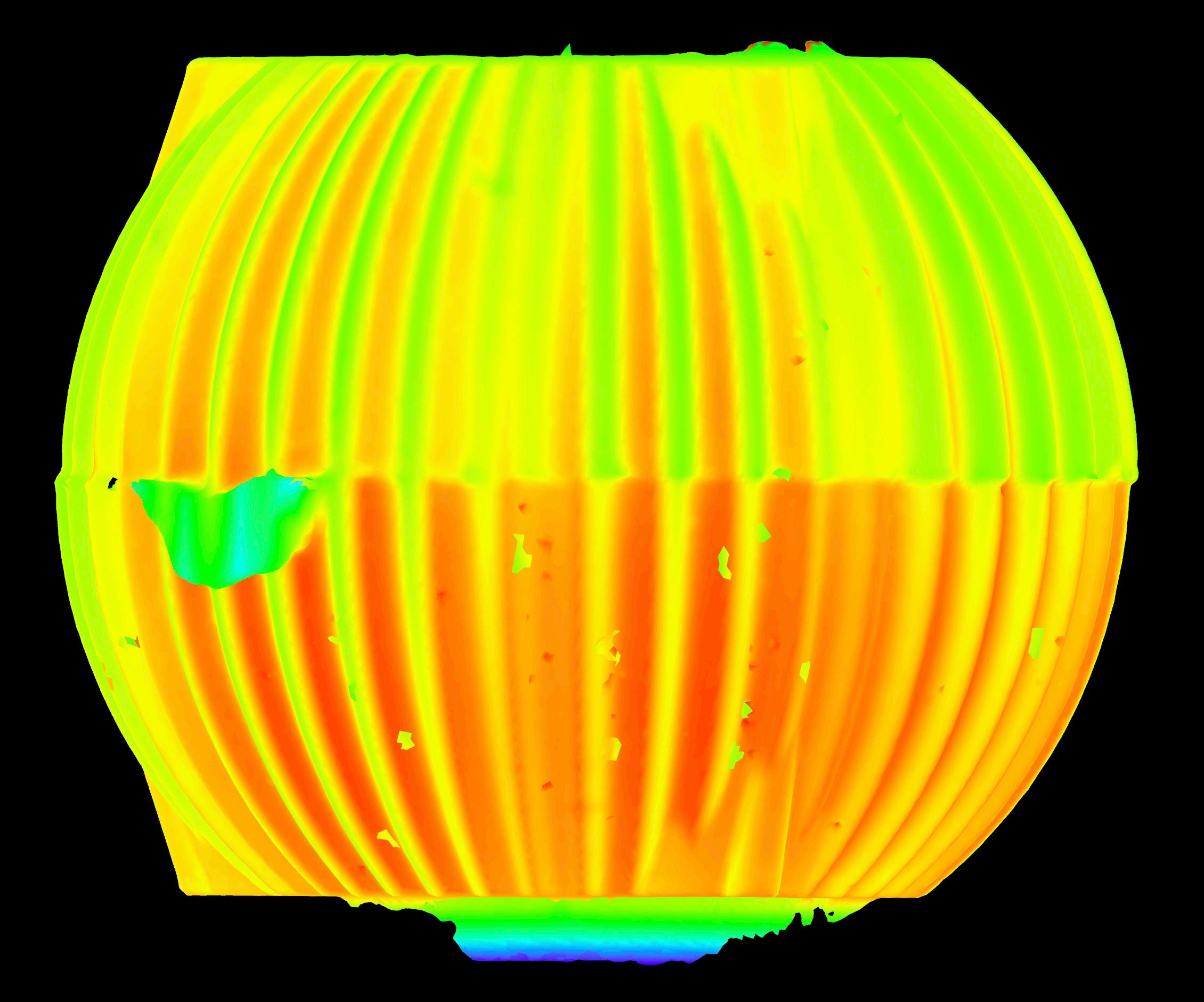
Figure 30: Core misalignment analysis for the final casting
Angle of tilt: 0.868 °
Distance of deviation: 1.961 mm
guidance, however, the accuracy of this process could be improved by creating a hole through the core and using a metal rod to hook the core into the mould. This would allow for more control over the orientation and ensure the core was correctly seated. If the core were to be entirely redesigned, features like interlocking supports could help prevent unwanted movement during mould assembly or casting. This could have prevented issues like the misrun in the initial casting attempt.
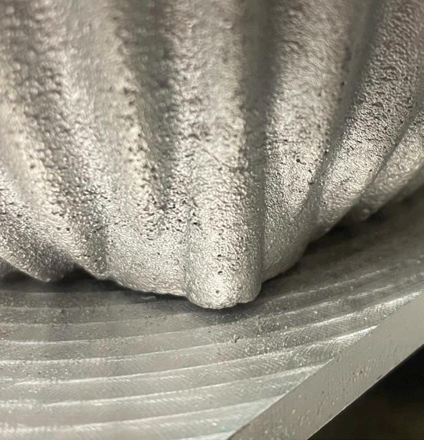
The finish when machining is dependent on the toolpaths and tools used. The surface finish in the case of the articulated speaker was achieved using a 6 mm ball nose end mill. The finish using this tool, paired with a 0.3mm stepover, was sufficient, however, there are some areas where the tool’s inability to fully reach into the fine crevices of the speaker’s articulated form can be seen (Figure 27, 28 and 32), affecting geometric form. A smaller 3 mm ball nose tool, combined with finer step-overs, would have allowed for greater geometric accuracy and improved the surface fidelity in these detailed areas. The finish of machined surfaces can be further evaluated using the ‘FLEXBAR NO.16008’ (Figure 31), but as a rotary parallel toolpath was used, there is no exact direct comparison to be made with the finish most closely reflecting the 12.5Ra value for turning.
The only significant machining error for the part arose from a misalignment in the Z-axis, which caused the 6mm ball nose tool to drill straight through the part (Figure 28). This highlighted the importance of precise calibration and alignment when operating the CNC machine. In this case, the imported 3D scan had been incorrectly
aligned in Fusion 360, resulting in a 10-degree rotational offset relative to the actual Z-axis. Although the toolpath appeared correct within the software, the misaligned scan led to a false point of origin, causing the machining operation to occur in an unintended location. This error underscores the necessity to verify digital to physical alignment prior to machining.
3D scanning proved an integral tool for analysing the casting and machining outcomes throughout the making process. Scans were taken of the failed casting, the final casting and the final machined component. To accurately digitise the geometry of the component, the Creaform 3D scanner was used, operating at a resolution of 1mm. A target plate was used for target positioning, with multiple scans required to capture the component in full. This was partially due to how difficult it was to capture the internal geometry of the articulated speaker. The scans were then aligned in VXelements software using a target-based approach. Once aligned, the scans were merged to create a complete mesh.
The work holding solution used to machine the articulated speaker noise aided with calibration, using consistent bolt












positions to align the component. This allowed the available stock thickness to be assessed by overlaying the 3D scan with the CAD model of the articulated speaker making it possible to plan the machining, ensuring no unintended breakthrough occurred during milling. This is an example of how integral 3D scanning was to the fabrication process.
Throughout fabrication, there were many factors that could have led to deviations: the printing and finishing of the pattern and core box, the core itself, the mould making process, the casting process and the machining process. 3D scanning and deviation analysis allowed for further interrogation into what stages could have caused specific deviations as well as the comparison of the component against specified benchmarks from standards set out by the British Standard Institute.
To gather the deviation analysis data, the MeshLab software was used, enabling the final casting and the final component to be analysed against their CAD counterparts. A target based approach was used once again within MeshLab to align the models before the deviation analysis was calculated within the software.
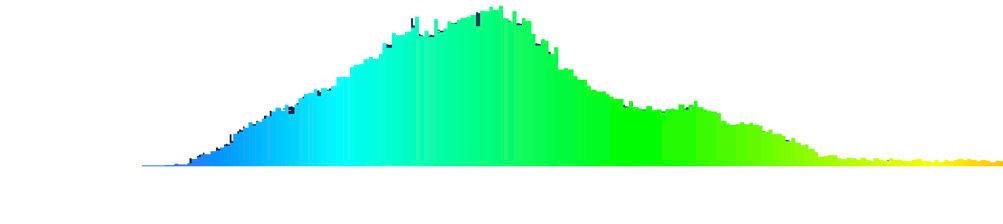
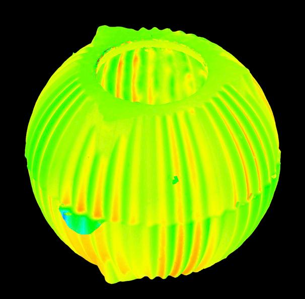
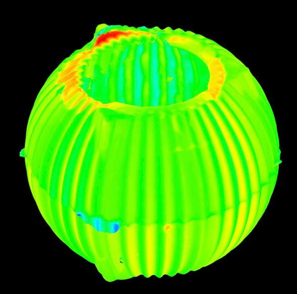
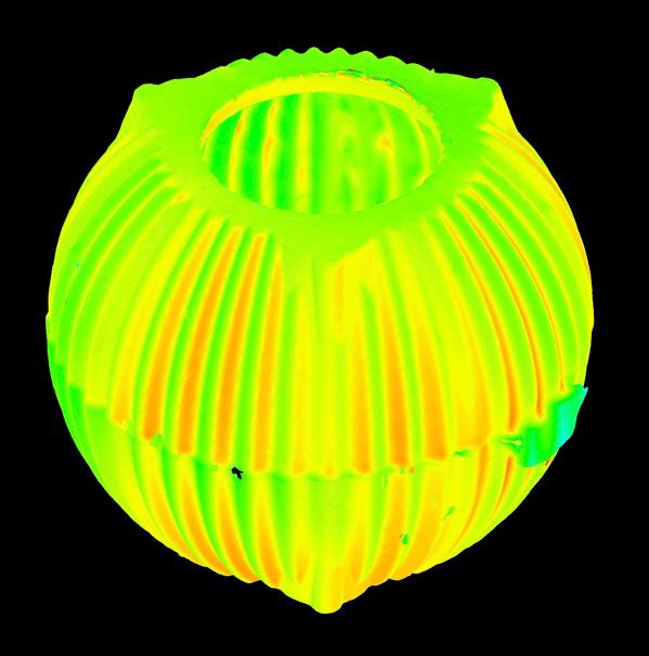
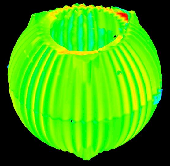
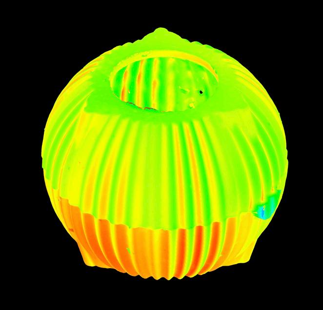
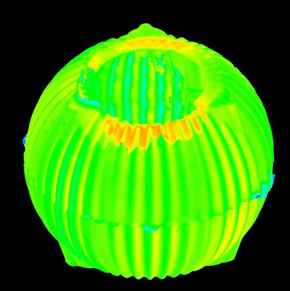
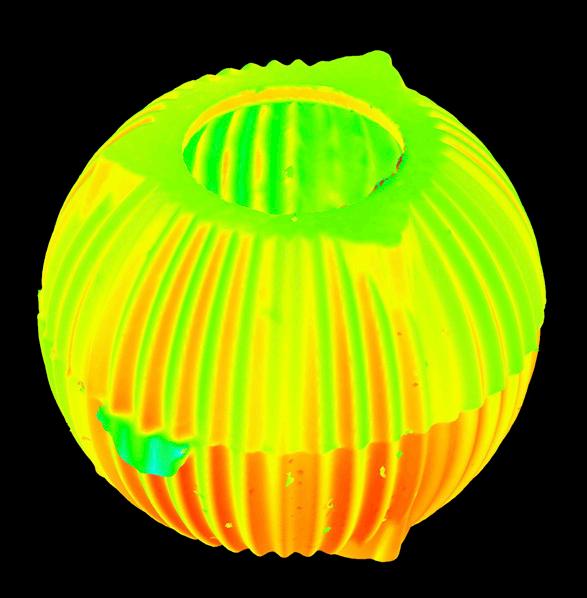
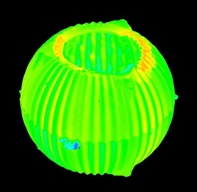
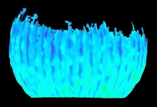
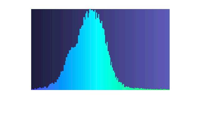
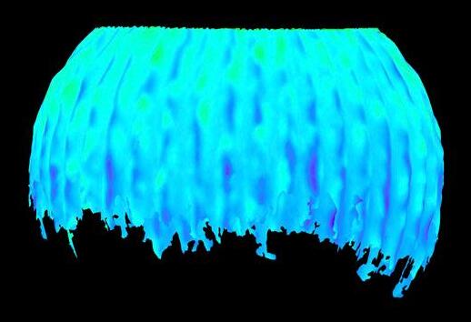
The British Standards Institute (BSI) dictates that for long series production, raw castings must lie between 9mm and 12mm, however for short series or one off production, raw castings may lie between 11mm and 13mm for clay-bonded sand cast moulding and 10mm to 13mm for chemically bonded sand casting moulding (BSI, 2023). Figure 33 shows that both the initial and final casting meet these geometric tolerances, with some of the higher deviations being attributed to the fact that the fettling was not very rigorous due to the necessity for post machining. The initial casting can be seen to be more geometrically successful
than the final casting, a mismatch in the pattern caused by poor moulding practises, as seen in Figure 29 is likely a considerable contributing factor for this.
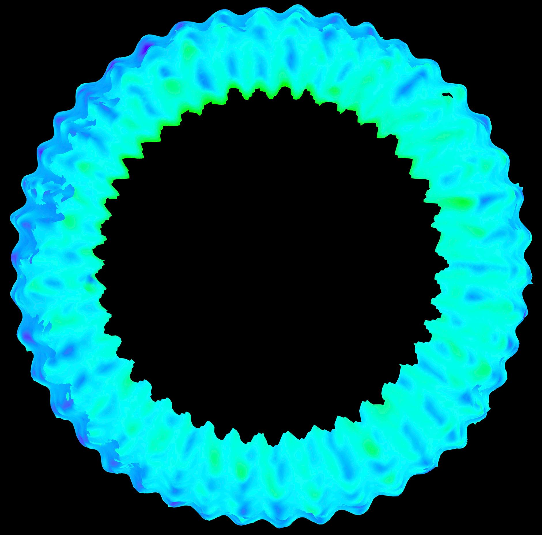
Whilst the geometry of the casting as a whole was important, the external surface was to be machined meaning the internal surface was most important to examine in the aftermath of the casting. Figure 34 shows the deviation analysis of the internal surface of the final casting alone. The internal surface meets the British Standards Institute geometric tolerance requirements (Table 5 and 6) and also exceeds the results of the casting when examined as a whole. Due to the difficulty obtaining a full scan of the inside of the articulated speaker, this data is incomplete, a factor that leaves the reliability of the data in question.
After machining, the component was scanned again to obtain data for the external machined surface and for the final component as a whole. Although the casting outcome can be considered a success due to its evaluation against BS 8062-4 (BSI, 2023), when evaluating the overall component, it becomes more complex due to the inclusion of machined surfaces. Whilst the geometry remains visually comparable to the design intent and has a numeric deviation, the absence of an initially defined tolerance framework, particularly for critical features, makes objective assessment more challenging.
Incorporating GPS methods at an early design stage could have set more meaningful targets to evaluate against. Without defined tolerances for the form and dimensions, it becomes difficult to determine whether deviations in the final component meaningfully affect the components performance. For instance, how much could the articulations deviate whilst still being effective for cancelling resonance?
An Investigation into the Experimental Prototyping
3.389992
0.400657
0.379204
0.632146 Variance: 0.399608

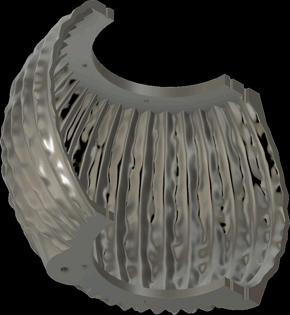
The alignment of the holes at either face of the speaker casing could have benefited from dimensional tolerances, defining how much deviation from the centreline would still permit effective subwoofer mounting. Similarly, if air tightness between the subwoofer and casing were critical, specifying surface flatness as a controlled feature would have been necessary. Despite this, the scope of what was important in regard to GPS was not clear to me at the start of this project due to my lack of experience. It is with the experience I now have that I can see how vital setting up a GPS framework is for ensuring functional performance through dimensional accuracy and geometric form. Figures 35 and 36 both illustrate how the geometrical product specification and verification could be laid to express the functional requirements for manufacturing the part using casting and post-machining.
Future prototypes should integrate GPS into the initial CAD modelling and casting drawings, outlining which features are critical to function and which are tolerant to deviation. Testing the assembled prototype would further refine these specifications, allowing for investigation into if the level of deviations present in the component effected the performance outcome or not. This experience highlights that the success of a prototype is not only measured by how closely it replicates a model, but by how clearly performance criteria are defined from the outset, as without them success remains partially subjective.
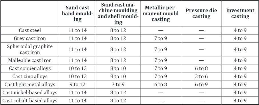
Table 5: Tolerance grades P and S for general tolerances for long series or mass production of castings (BSI, 2023)
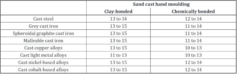
Table 6: Table 6: Tolerance grades P and S for general tolerances for short series or single production of castings (BSI, 2023)
Final Casting
Table 7: Table 7: Empirical rule calculations, assuming a normal distribution
Figure 35: Geometrical Product Specification and Verification drawing of the articulated speaker I (Leung, 2025)
3X M5X0,7-6H RIGHT-HAND THRO
Ø0,5 D E B
LOWER VIEW (1:1)
DO NOT SCALE FROM THIS DRAWING
STANDARD(S): BRITISH STANDARD (BS) 8888 TECHNICAL PRODUCT SPECIFICATION
ISO 8015 GEOMETRICAL PRODUCT SPECIFICATION
QUANTITY: SEE B.O.M. (BILL OF MATERIALS) ON DRAWING J00/0
MATERIAL: ISO 513 GROUP 'N' NON-FERROUS METAL ALUMINIUM ALLOY LM4 OR LM25 SUITABLE FOR GREEN SAND MOLD CASTING PROCESS
FINISH: SURFACE FINISH ON INDICATED FEATURE(S) TO ANSI B 46.1 SURFACE TEXTURE AND AREAL ROUGHNESS WHERE INDICATED
PRODUCTION: SCHEDULE OF OPERATIONS REFERENCE: J00_17_A_SCOP
INSPECTION: TEST PART QUALITY CONTROL (QC) AGAINST A GAR C9 MICROFINISH COMPARATOR FOR AREAL AS CAST FEATURES
FIRST ARTICLE INSPECTION REFERENCE: J00_17_A_VERI
DISASSEMBLY AND MATERIAL RECOVERY AT END-OF-SERVICE: MARK PART WITH ALU
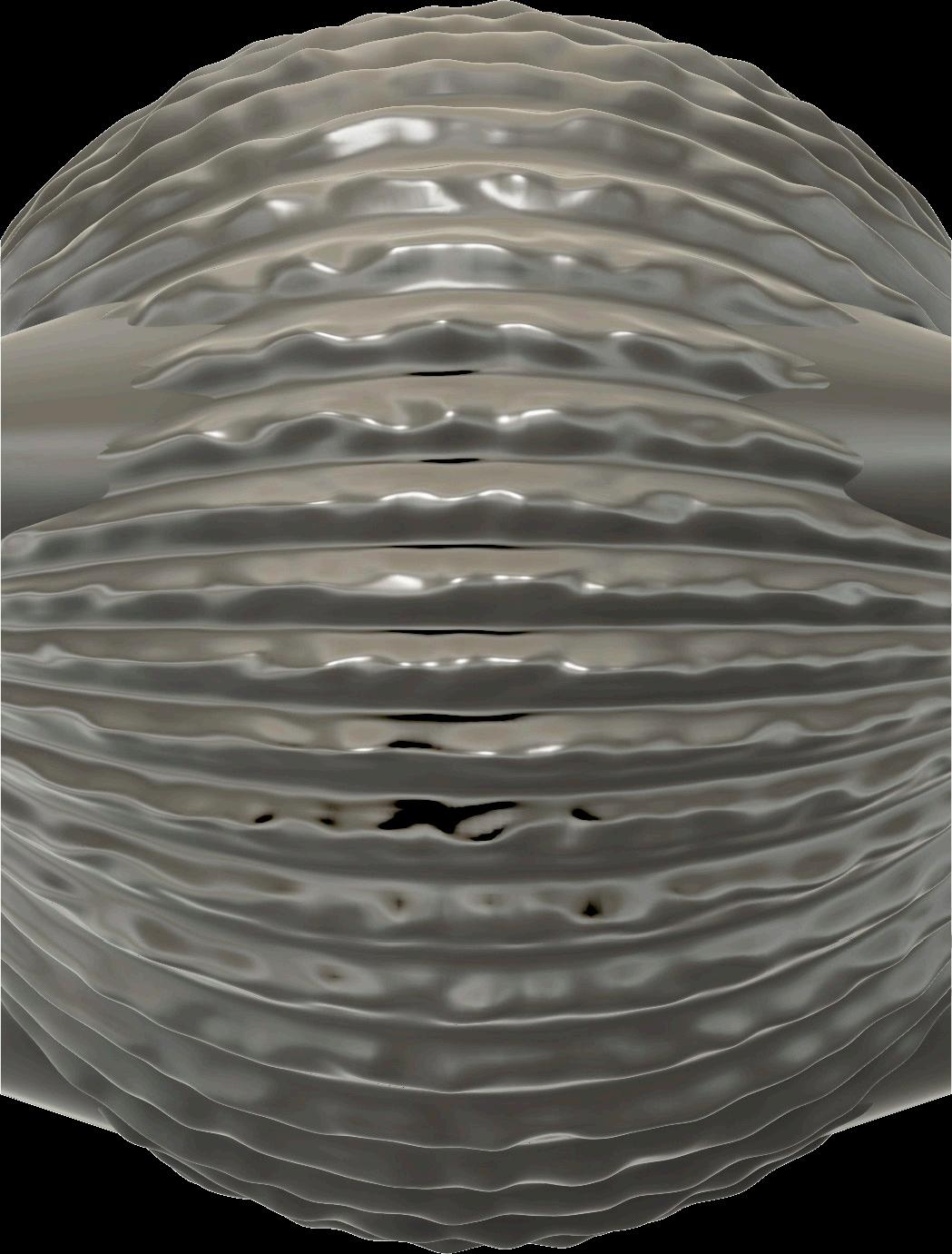
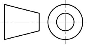
Figure 36: Geometrical Product Specification and Verification drawing of the articulated speaker II (Leung, 2025)
DO NOT SCALE FROM THIS DRAWING
STANDARD(S): BRITISH STANDARD (BS) 8888 TECHNICAL PRODUCT SPECIFICATION
ISO 8015 GEOMETRICAL PRODUCT SPECIFICATION QUANTITY: SEE B.O.M. (BILL OF MATERIALS) ON DRAWING J00/0
MATERIAL: ISO 513 GROUP 'N' NON-FERROUS METAL ALUMINIUM ALLOY LM4 OR LM25 SUITABLE FOR GREEN SAND MOLD CASTING PROCESS FINISH: SURFACE FINISH ON INDICATED FEATURE(S) TO ANSI B 46.1 SURFACE TEXTURE AND AREAL ROUGHNESS WHERE INDICATED PRODUCTION: SCHEDULE OF OPERATIONS REFERENCE: J00_17_A_SCOP
INSPECTION: TEST PART QUALITY CONTROL (QC) AGAINST A GAR C9 MICROFINISH COMPARATOR FOR AREAL AS CAST FEATURES FIRST ARTICLE INSPECTION REFERENCE: J00_17_A_VERI DISASSEMBLY AND MATERIAL RECOVERY AT END-OF-SERVICE: MARK PART WITH ALU
BI-LATERAL SECTION
BIRD'S EYE ISOMETRIC VIEW
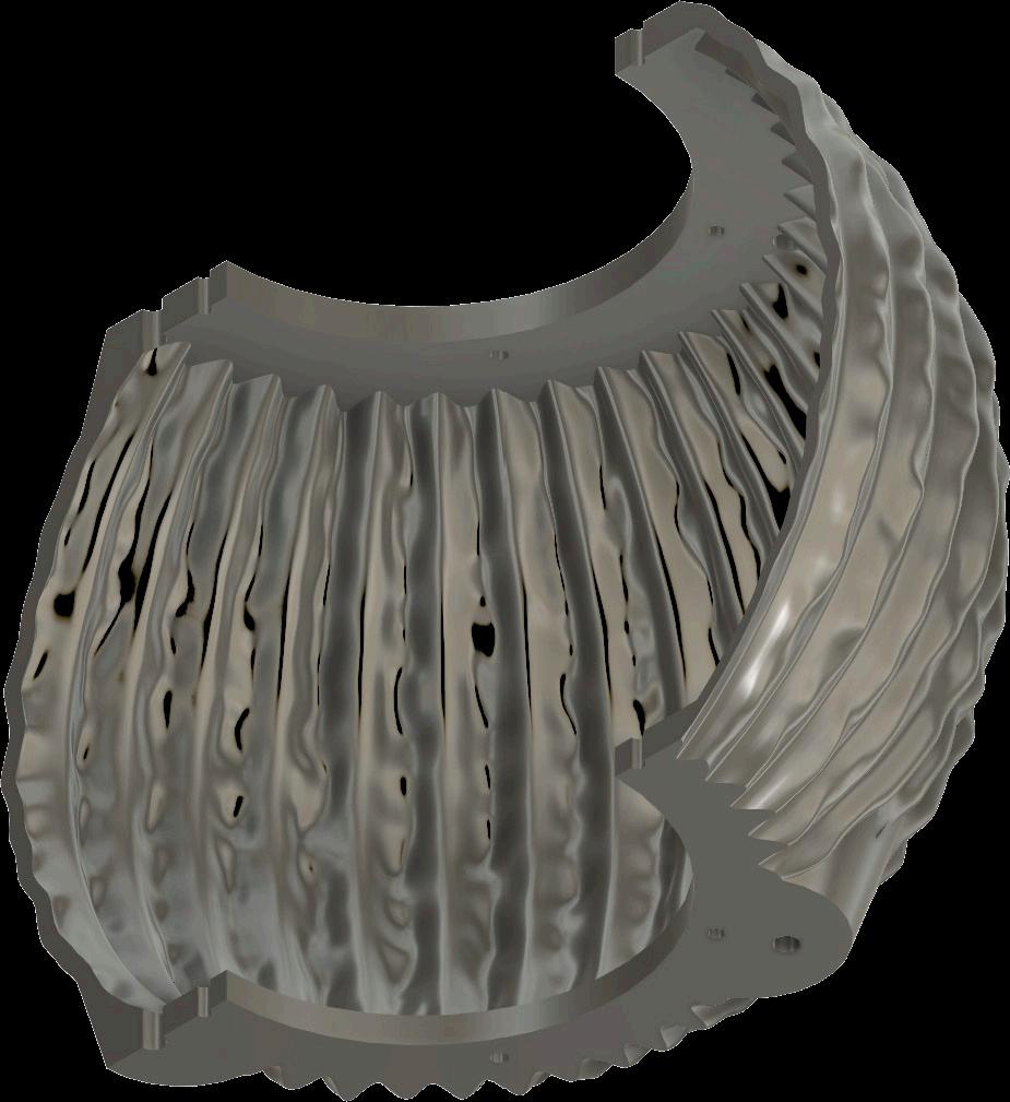
BI-LATERAL SECTION WORM'S EYE ISOMETRIC VIEW
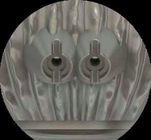
During the collaboration with Philip Beesley, a miscommunication occurred between the designer and fabricator when it became clear that the speaker was intended to fit a specific mounting system, information that had not been included in the initial design requirements. As a less experienced fabricator, I hadn’t thought to ask about mounting constraints early in the process, whereas a more seasoned practitioner likely would have. This experience reflects a common challenge in industry, where gaps between design intent and fabrication realities can lead to costly or time-consuming revisions. It highlighted the importance of proactive communication and the need to anticipate functional requirements beyond what is explicitly provided. Learning to navigate and bridge these gaps not only strengthens the relationship between designer and maker but also develops critical skills in design questioning, technical foresight, and collaborative problem-solving, skills that will carry forward into future practice. Figure 37 shows the size of the component versus the mounting system it was supposed to attach to. To rectify the situation, a custom-sized mounting system will be 3D printed to fit the dimensions of the current speaker.
Another challenge arose when the casting crucible cracked in December, halting production. A replacement had to be ordered from Germany, as the crucibles are not readily available in the UK. Unfortunately, the shipment was lost in transit, and the secondary replacement did not arrive until February, causing a significant delay in the manufacturing timeline. This setback underscored the unpredictability of supply chains and mirrored the realities of fabrication, where material and equipment availability can critically impact project progression.
37: Drawing of the component and ideal mounting system
When looking at the finished articulated speaker, it is easy to see a final product that could be mass-produced. Sand casting, while versatile and cost effective for low production volumes, is not the most efficient method for mass production. The one time use of each mould means production time is increased and labour are increased, both factors that increase costs. Additionally, the articulated speaker requires extensive post machining to achieve the desired aesthetics when sand cast. A casting process that provides better dimensional accuracy to aid with machining or can deal with the presence of undercuts to produce the articulations could prevent the majority of post machining requirements.
For higher production volumes, permanent mould casting could be used. This process involves pouring molten aluminium into a reusable mould in a process that is much like sand casting. Permanent mould casting requires two halves coming together to make the mould, but instead of sand, metals like steel are used to form the mould (Francis, 2016). This provides a better surface finish and better dimensional accuracy than sand casting, although the mould is comparably more expensive than sand casting. When permanent mould casting, the mould has to come apart in two halves, meaning undercuts would still be a problem and significant machining would still be needed for the articulated speaker. In this case, die casting would likely be the more appropriate casting method. Molten aluminium is injected into moulds at high pressures, allowing for quick production cycles and excellent surface finishes with high levels of dimensional accuracy (Francis, 2016). Despite this, die casting requires a substantial investment into the tooling, with repeats of 2500 needed to make the method economical (Stacey, 2001).
The scope of this research aimed to interrogate the design to fabrication process through the making of a cast and machined aluminium speaker. While the final component demonstrated the strength of a materially engaged design process, it also revealed several technical and procedural limitations that present opportunities for further refinement looking to the future.
Early GPS definitions in reference to the BS 8062 could have been established to set up what dimensions would be most important to consider and their respective tolerances. The CAD model, in hindsight, should have incorporated these allowances from the offset. Misalignment of the core led to off centre holes and inconsistent external stock, which affected both the geometry and machining efficiency. A more reliable core locating method would have improved the consistency of both the internal and external surfaces.
The ability to reduce excess material would have had the dual benefit of saving machining time and reducing material waste.
Internally, the rough surface finish reflected the difficulty in achieving full CO₂ permeation within a large, intricate core. Future iterations should test more controlled core curing environments, and possibly redesign the venting strategy to ensure more even gas access Additionally, a sand mould surface hardness tester could have been used to test and improve the surface quality and therefore the mould integrity, contributing to better outcomes during pouring.
These insights extend beyond the object itself, as work holding for the somewhat irregular component proved more complex than anticipated. The speaker’s asymmetry, coupled with surface variation from casting, made accurate CNC referencing challenging. This experience underscored the importance of planning machining sequences alongside the design and considering how uncertainty in casting affects the spatial logic of milling.
Looking ahead, the lessons learned throughout this process will be directly applied to the development of a new component within the Design Practise 3 module. Tasked with designing a theatre in Paris, the component aims to integrate bone conduction technology and guide the audience sightlines in the theatre through a façade panel.
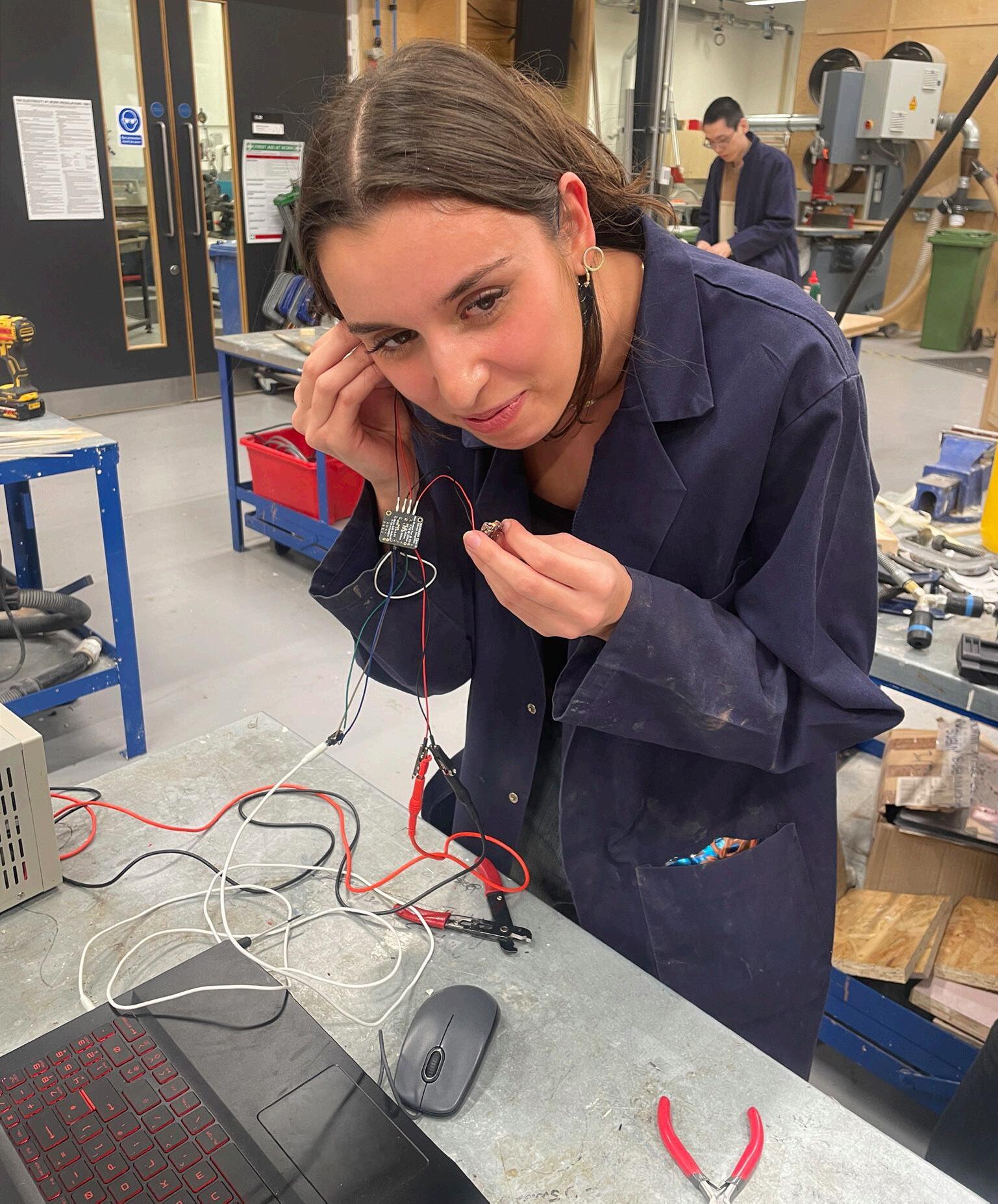
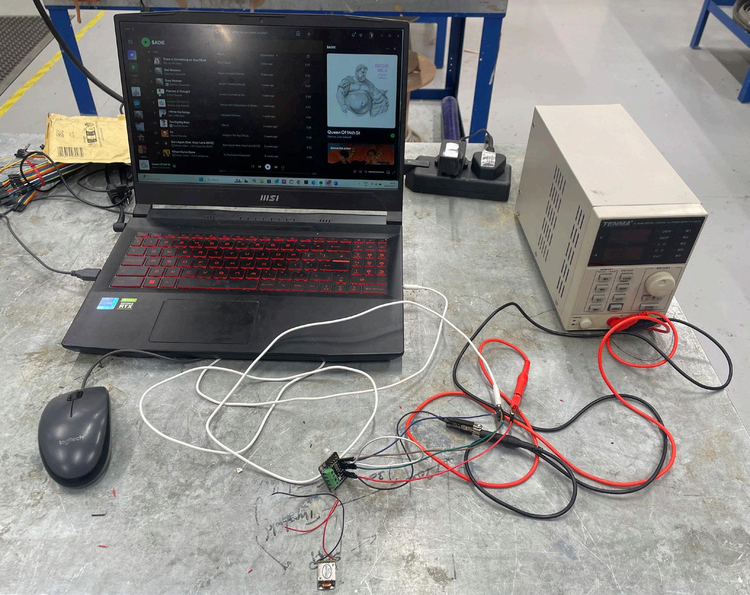
This builds on the responsive, performative function explored in the speaker, but adapts it to architectural scale and occupancy. A breadboard prototype of the bone conduction technology was developed to test it’s effectiveness with much success. The casting and machining skills developed through this dissertation,
particularly those around core design, machining considerations and tolerance strategy will be embedded into the process from conception.
Ultimately, this dissertation has shifted the role of prototyping in my work from something evaluative to something generative. Future fabrication will begin not just with form, but with a critical understanding of what can be made, and how that process shapes the possibilities of design.
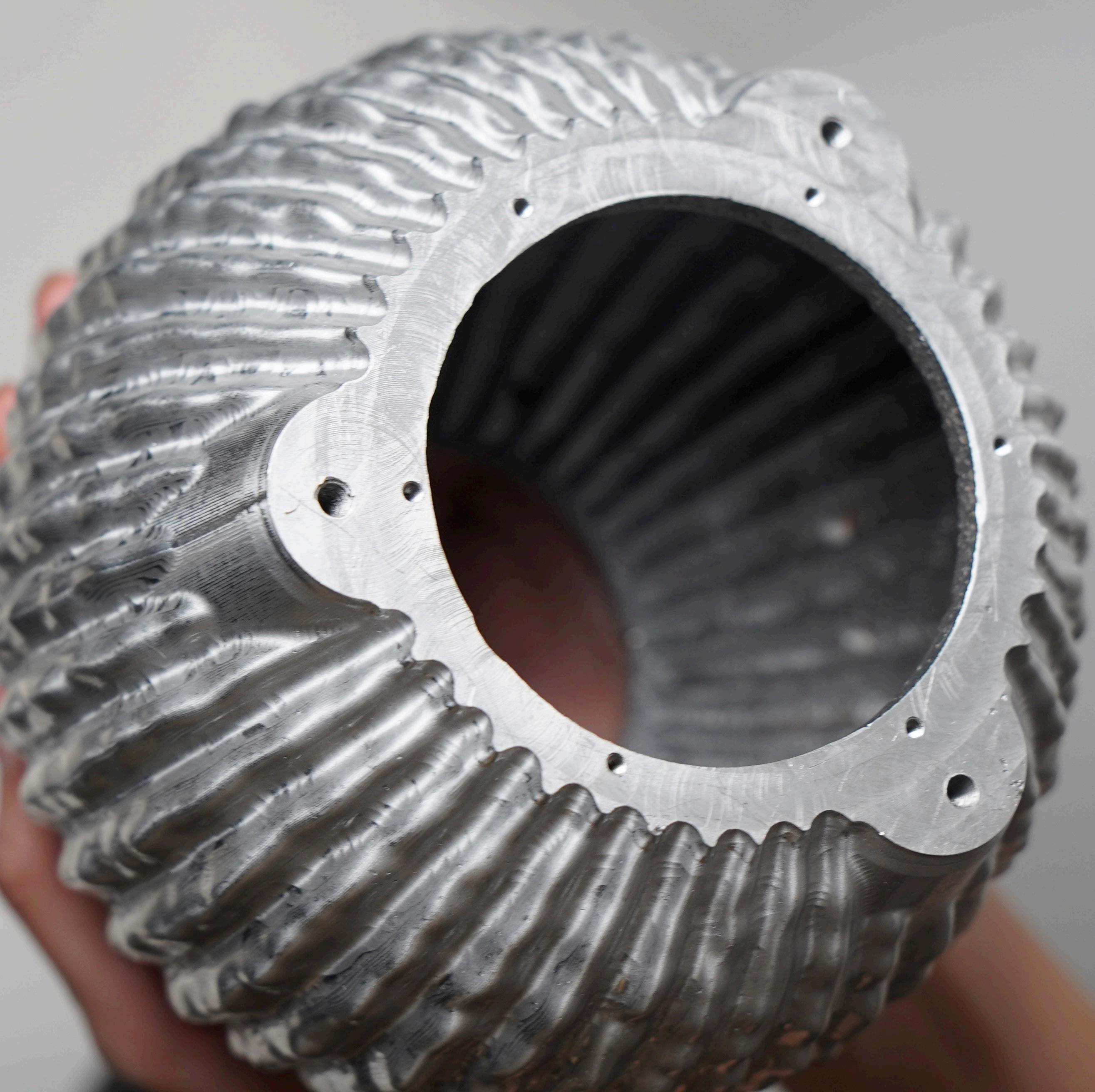
When reflecting on the outcome of this dissertation, the lessons I have learnt along the way are all present in the final articulated speaker. Every element represents the successes and failures of the individual processes and decisions that went into achieving the final component, my role becoming a synthesis of disciplines combining architecture, engineering, fabrication and foundry practices.
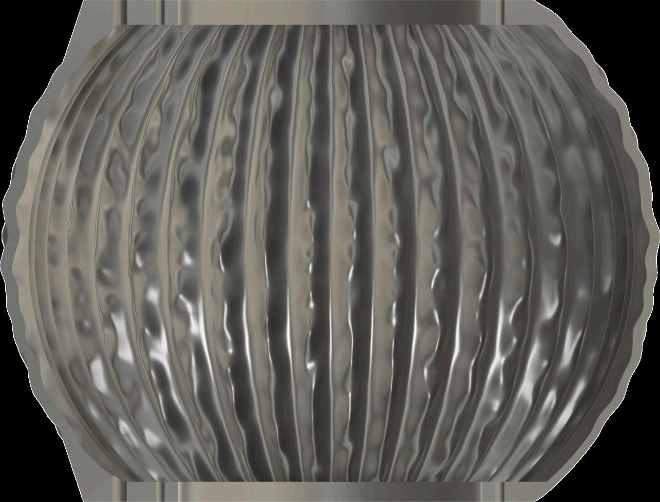
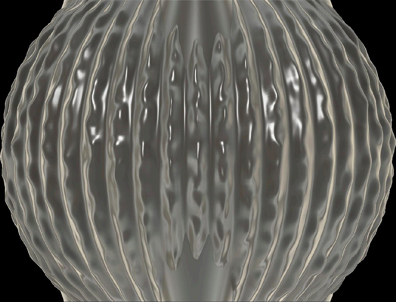
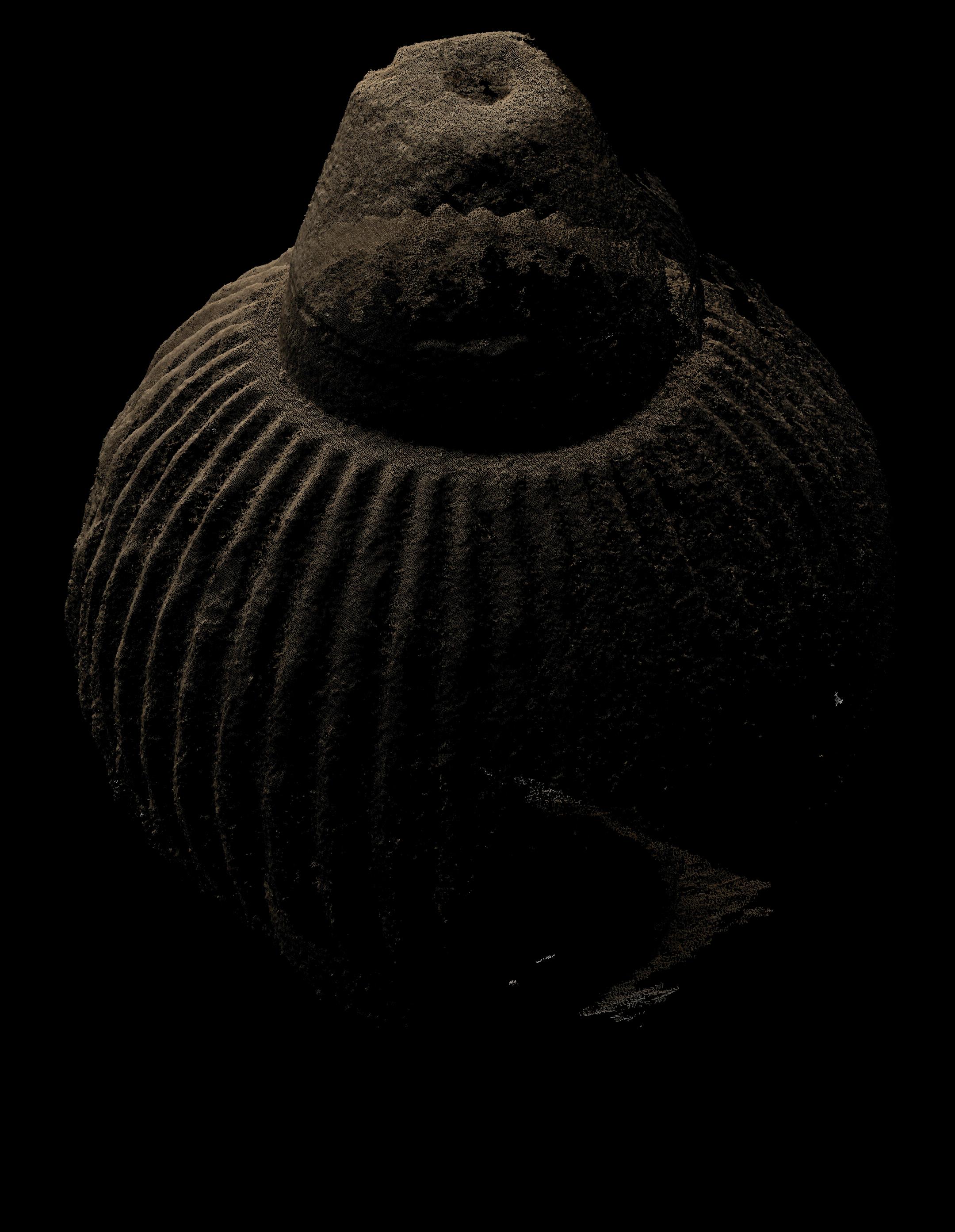
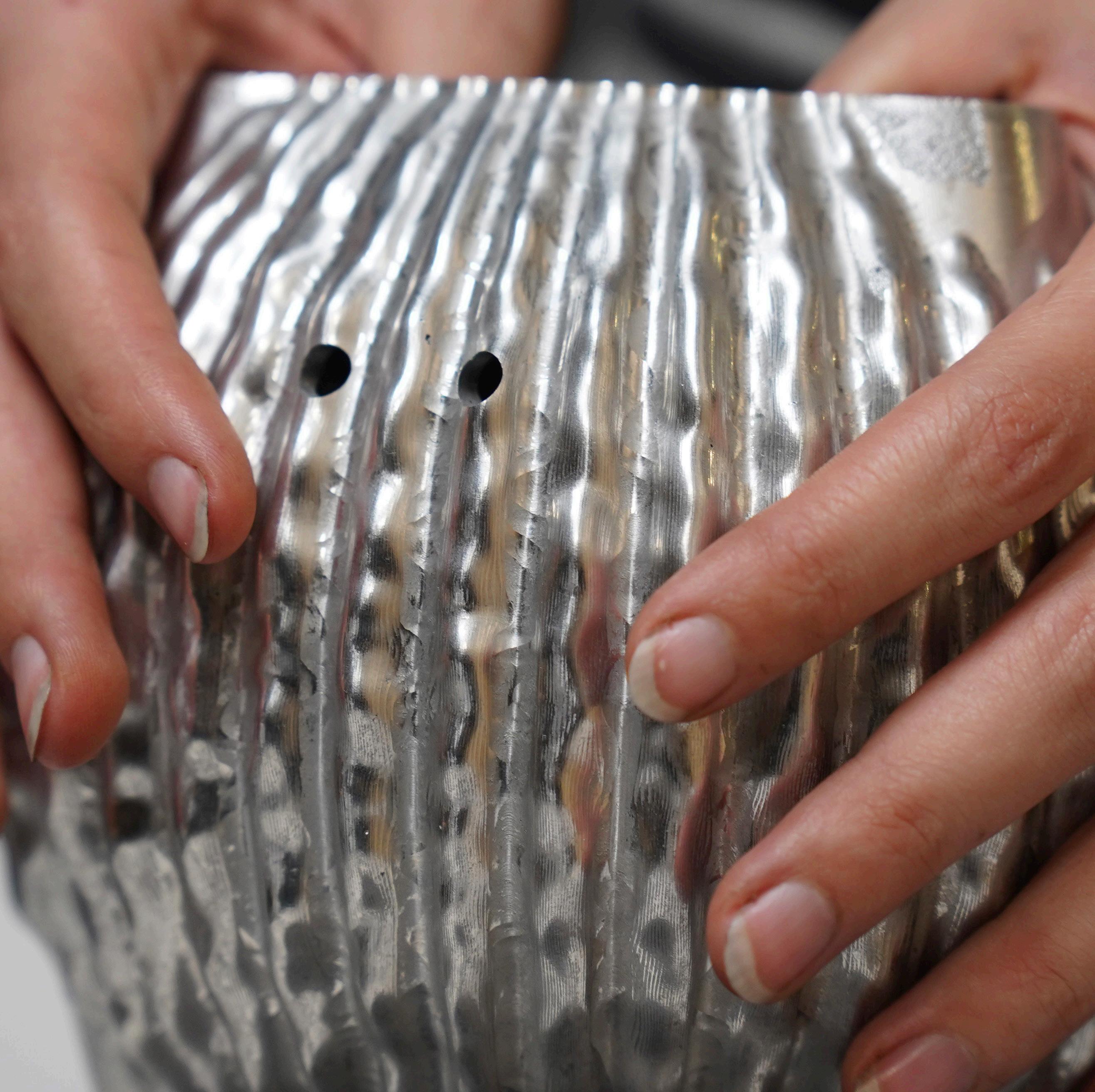
The external surface shows the full sequence of fabrication, from the texture of the original sand casting still visible in some areas, to the stepovers of the toolpaths or the limitations of the tool access. In contrast, the internal surface, formed by the sand core, presents a different set of constraints. Its rough surface finish reveals the difficulty in achieving consistent carbon dioxide permeation for a complex core. The final speaker captures the memory of its making, reflecting a sequence of choices shaped by constraint.
At the beginning of this dissertation, the making processes (pattern making, core box making, core preparation, mould preparation, casting, machining) to create the articulated speaker were succinct and separate. Through the act of making, the way each process influenced the next became clearly interconnected. This interconnection has shaped my approach to making, no longer looking upon the process as a linear sequence, but as a system of responsive, iterative actions. Future work will approach fabrication not as a set of isolated operations, but as a symbiotic process, where design is continually refined.
Looking more broadly, this dissertation reinforces a core argument that has shaped this dissertation: architecture is not created through the act of drawing, but through the act of construction, with construction being a culmination of dialogue with material, tools, and systems shaped by the hands that bring it into being. In a profession increasingly defined by distance between designer and fabricator, much like the experience of collaborating with Philip Beesley, where miscommunications can occur, this dissertation insists on the necessity for proximity with materials and processes successful for realisation, with the dissertation following the process of making unfolding in full scale and in real time.
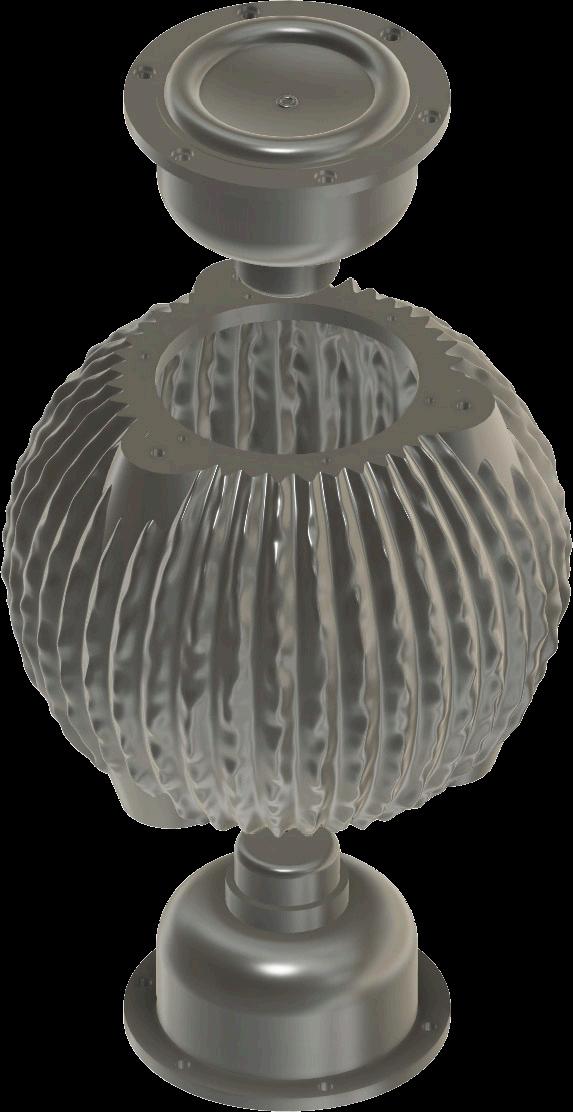
Figure 1: The Articulated Speaker I
Figure 2: Philip Beesley ‘Noogenesis Sculpture’ 2023
Figure 3: Initial casting options
Figure 4: Previous 3D printed speaker vessels from Philip Beesley’s ‘Grove’, Venice Biennale, 2021
Figure 5: Graphs showing spectral decay data for typical speaker casing materials (MAGICO, n.d.)
Figure 6: Draft Angle Analysis for the Initial Articulated Speaker Design
Figure 7: Draft angles for the redesigned speaker
Figure 8: Drawing of the redesigned component 1:2
Figure 9: Diagram of the Components Required to Create the Casting, Photograph (Leung, 2025)
Figure 10: Casting core iterations for initial and final locator design
Figure 11: Pattern iterations 1:2 Isometric
Figure 12: Core box iterations 1:2 Isometric
Figure 13: Photographs of the core-making process
Figure 14: Schematic casting diagram adapted from Fundamentals of Aluminium Metallurgy (Lumley, 2010)
Figure 15: Photographs of the casting process
Figure 16: Casting in action - LM6 pouring temperature 725°C (Aluminium Alloy Manufacturing & Recycling Association, 2018)
Figure 17: Photographs of the casting outcome
Figure 18: Diagram of the sand box (flask) of the bronze sand castings for Regional Rail (Stacey 2001)
Figure 19: Machining problems encountered and measures taken to solve them
Figure 20: Thickness variation in the casting
Figure 21: CNC machining setup showing casting against the idealised geometry
Figure 22: Progress photograph of the first machining pass
Figure 23: CNC articulation machining setup
Figure 24: C9 Micro finish comparator surface finish scale
Figure 25: Casting finish interior and exterior photographs
Figure 26: Comparing a section of the failed casting against the C9 Micro finish comparator surface finish scale
Figure 27: The milled surface of the articulated speaker after the second pass
Figure 28: Casting defects and machining errors
Figure 29: Pattern mismatch and deviation analysis for the final casting
Figure 30: Core misalignment analysis for the final casting
Figure 31: FLEXBAR NO.16008
Figure 32: Analysis of tool and toolpath effect on geometric form
Figure 33: Deviation analysis comparison of the initial and final casting
Figure 34: Deviation analysis for the internal surface of the final casting
Figure 35: Geometrical Product Specification and Verification drawing of the articulated speaker I (Leung, 2025)
Figure 36: Geometrical Product Specification and Verification drawing of the articulated speaker II (Leung, 2025)
Figure 37: Drawing of the component and ideal mounting system
Figure 38: The Articulated Speaker II
Figure 39: Photograph testing the bone conducting electronics
Figure 40: Photograph of the testing set-up
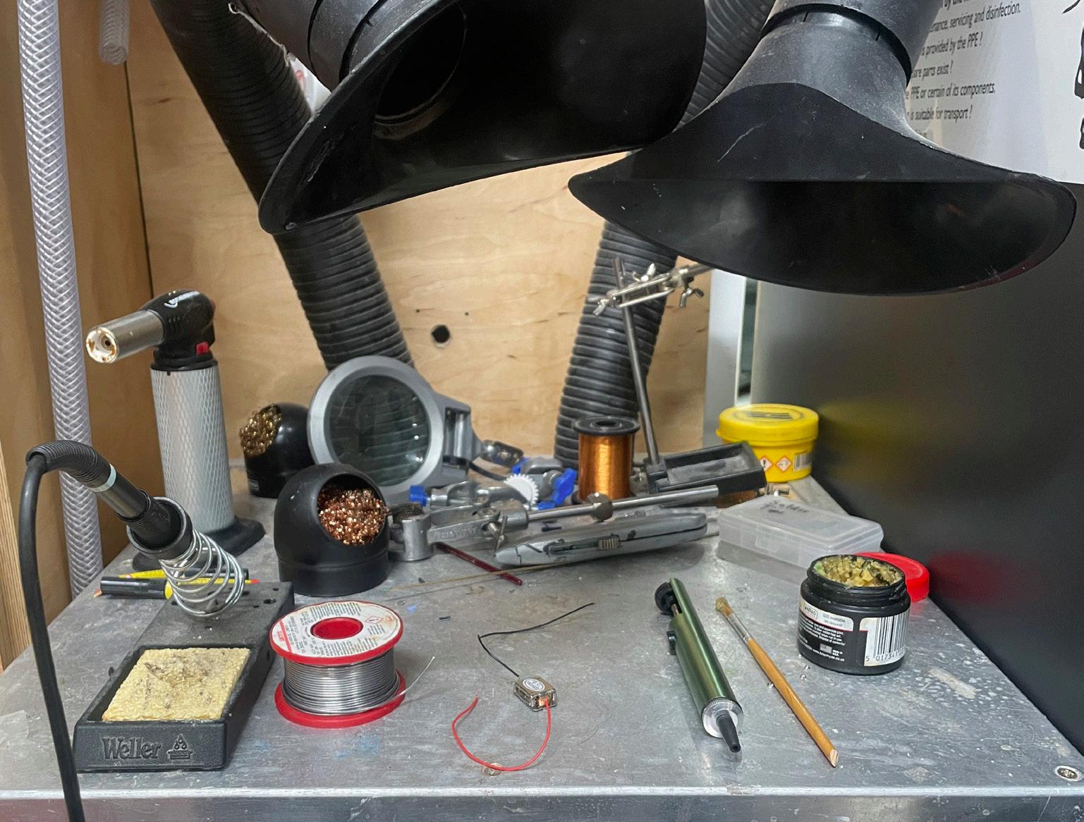
Figure 41: Photograph of the soldering set-up
Figure 42: The Articulated Speaker III
Figure 43: Map of the globalization of manufacture for the articulated speaker
Figure 44: Ethics declaration and approval
Table 1: Casting Comparisons (Adeleke et al., 2022)
Table 2: Design requirements for the Articulated Speaker set by Philip Beesley
Table 3: Adapted Table of Comparison of LM4, LM6 and LM25 Aluminium Alloy Composition (Aluminium Alloy Manufacturing and Recycling Association, 2008)
Table 4: Adapted Table of Comparison of LM4, LM6 and LM25 Aluminium Alloy Properties (Aluminium Alloy Manufacturing and Recycling Association, 2008)
Table 5: Tolerance grades P and S for general tolerances for long series or mass production of castings (BSI, 2023)
Table 6: Tolerance grades P and S for general tolerances for short series or single production of castings (BSI, 2023)
Table 7: Empirical rule calculations, assuming a normal distribution
List of Abbreviations
3D – Three Dimensional
AM - Additive manufacturing
BSI - British Standards Institute
CAD - Computer Aided Design
CAM - Computer Aided Manufacture
CNC - Computer Numerical Control
CO2 - Carbon dioxide
G-Code - Geometric Code
GPS - Geometric Product Specifications
LCA - Life Cycle Assessment
LM - Lynall Metal
PLA - Polylactic Acid
PPC - Polyester powder coating
PVDF - Polyvinyl fluoride
RMA - Required Machining Allowance
RMS - Root Mean Square
Alloy – ‘Combination of two or more metals to form enhanced properties’ (Stacey, 2001)
Anodising – Anodising is an electrochemical process that thickens the natural oxide layer occurring on an aluminium surface to enhance corrosion resistance and improve appearance (Stacey, 2023).
Casting – ‘general term for products at or near finished shape, formed by solidification of a metal or alloy in a mould’ (BSI, 2007)
Cope – ‘In a split pattern, sand casting the top half of the sand mould or flask is called the cope’ (Stacey, 2001)
Core – ‘piece inserted in the mould to shape part of the moulded part’ (BSI, 2007)
Core Box – ‘The box in which cores are made’ (Joseph, 1959)
Crucible – ‘A vessel, usually of earthenware, made to endure great heat, used for fusing metals’ (Oxford English Dictionary, 2025)
Die Casting – ‘Metal casting formed in a metal, typically steel, mould suitable for high volume production’ (Stacey, 2001)
Draft Angle – ‘angle added to a geometrical feature of a pattern or mould to ensure the easy removal of the pattern or moulded part from the mould or to improve the quality of the product’ (BSI, 2007)
Drag – ‘In a split pattern, sand casting the bottom half of the sand mould or flask is called the drag’ (Stacey, 2001)
Electrolysis – ‘Chemical decomposition produced by the passage of an electric current through a liquid containing ions; the process of passing a current through a liquid to produce a chemical reaction at the electrodes.’ (Oxford English Dictionary, 2025)
Fettling – ‘process of any type which removes unintended superfluous material from the raw moulded part’ (BSI, 2007)
Finishing – ‘process of any type used to bring the moulded part into compliance with specifications by addition or removal of material or by deformation of the surface(s)’ (BSI, 2007)
Flask – ‘The boxes which contain the sand used to form a sand casting are called the flask’ (Stacey, 2001)
Gate – ‘channel or orifice through which material flows from the runner or the sprue into the cavity’ (BSI, 2007)
Gas Porosity – ‘Gas dissolved in the molten metal may lead to fine round voids in the solidified casting.’ (Aluminium Alloy Manufacturing & Recycling Association, 2018)
Heatsink – A heatsink is a heat exchanger that dissipates excess thermal energy from electronic components using high conductivity materials like aluminium or copper (Abbas, 2024)
Hot Tearing – ‘Cracking on solidification is caused by tensile stresses building up in the metal as parts of
the casting shrink on solidification.’ (Aluminium Alloy Manufacturing & Recycling Association, 2018)
Inclusions – ‘Inclusion defects occur as the existence of insoluble particulate material trapped within the casting during solidification.’ (David, 2011)
Life Cycle Assessment – ‘compilation and evaluation of the inputs, outputs and the potential environmental impacts of a product system throughout its life cycle’ (Finkbeiner et al., 2006)
Lost Foam Casting – ‘A metal casting formed in a ceramic ‘jacket’, or investment mould, from which the foam pattern is vaporized by the action of the hot metal as it is cast’ (Stacey, 2001)
Lost Wax Casting – ‘A metal casting formed in a ceramic ‘jacket’, or investment mould, from which the wax pattern has been removed by heating, prior to casting.’ (Stacey, 2001)
Machining – ‘process of any type used to bring the moulded part into compliance with specifications on the final machined moulded part by removal of material’ (BSI, 2007)
Mismatch – ‘imperfection(s) on a moulded part caused by misalignment or displacement or dimensional differences between the mould components resulting in a step on the surface of a moulded part or varying thickness of a moulded part’ (BSI, 2007)
Misrun – ‘A misrun occurs when metal fails to fill the mould cavity’ (Aluminium Alloy Manufacturing & Recycling Association, 2018)
Mould – ‘elements or materials encompassing a cavity’ (BSI, 2007)
Omnidirectional Sound Source – A device designed to emit sound uniformly in all directions, creating an even distribution of sound across a 360 degree radius (Ibarra, Ledesma & Lopez, 2018).
Parting Line – ‘representation of the parting surface on a drawing of the moulded part’ (BSI, 2007)
Pattern – ‘tool which is a replica of the shape to be produced having the purpose of forming the cavity in the mould’ (BSI, 2007)
Polyester powder coating (PPC) – ‘Powder coatings are solvent-free paints applied to metals and other conductive surfaces.’ (Stacey, 2023)
Polyvinyl fluoride coating (PVDF) – ‘Polyvinyl fluoride coatings (PVDF or PVF2) are based on a mixture of polyvinylidene fluoride resin (minimum 70%) and acrylic resin (maximum 30%)… PVDF is a multicoat system requiring a colour coat and a top clear coat’ (Stacey, 2023)
Required Machining Allowance – ‘smallest possible value of the machining allowance which enables the machined feature to comply with specifications’ (BSI, 2007)
Resonance – ‘The reinforcement or prolongation of sound by reflection or by the synchronous vibration of a surrounding space or a neighbouring object. Also: a sound, or quality of sound, resulting from this.’ (Oxford English Dictionary, 2025)
Riser – ‘reservoir of material which compensates for the volumetric contraction of the material in the mould during solidification’ (BSI, 2007)
Sand Casting – ‘A metal casting formed in a sand mould.’ (Stacey, 2001)
Undercuts – A space formed by the removal or absence of material from the lower part of something. (Oxford English Dictionary, 2025)
Volumetric Shrinkage – ‘difference in volume between a solidified and cooled moulded part and its mould cavity’ (BSI, 2007)
Abbas, E. F. (2024). ‘“An overview of heat sink technology”. International Journal of Applied Mechanics and Engineering’. International Journal of Applied Mechanics and Engineering, pp. 1–23.
Adeleke, A., Oki, M., Ikubanni, P. and Anyim, I. (2022). ‘Recent Development in Casting Technology: A Pragmatic Review’. Revue des composites et des matériaux avancés.
Almaghariz , E. S. (2015). Determining When to Use 3D Sand Printing: Quantifying the Role of Complexity.
YOUNGSTOWN STATE UNIVERSITY .
Aluminium Alloy Manufacturing & Recycling Association. (2018). British & European Aluminium Casting Alloys. ALUMINIUM FEDERATION.
Arnela , M., Martínez-Suquía, C. and Guasch, O. (2021). ‘“Characterization of an omnidirectional parametric loudspeaker with exponential sine sweeps”’. Applied Acoustics.
Baddoo, N. R. (1996). Castings in construction. Ascot: Steel Construction Inst (SCI publication, 172).
Bralla, J. G., Hornbruch, F. W., McMullin, W. B., Skillingberg, M. H., Harper, C. A., Stein, J., Strasser, F., Fischlin, J. K., Langlois, K., Saperstein, H., Wick, C., Everhart, J. L., Swan, B. H., Powell, R., Hellman, P. M., Guichelaar, P. J., Castellano, E. N., Tannenberg, D. E. A., Hanson, A. D., Slezak, T., Lewis, F. W., Judson, T. W., Roseliep, R., Sopko, P., Cann, R., Mowry, W., Piccinino, L. J., MacLeod, R. B., Militzer, R. W., Liu, C. R., Haley, S., Coggins, G., Throop, J. W., Bryan, W. J., Jones, J. F., Gillespie, L. K., Zuppann, E. C., Niebel, B. W., Spinosa,
R. J., MacLaren, J. L., Bainbridge, R. W., Mohr, J. G., Hodska, N. S., Bralla, J. R. C., Tyrrell, W. R., Sommer, J. G., Beck, R. D., Wilcox, J. C., Casteras, J., Schneberger, G. L., Cocco, J., Gonas, A. J., Musbach, A. J., Tonini, D. E., Adams, D. A., Pannier, R. A., Fuchs, H. O., Spring Manufacturers Institute, and Teledyne Landis Machine (eds). (2000). Design for manufacturability handbook. 2nd ed. New York: McGraw-Hill (McGraw-Hill handbooks).
BSI. (2007). ‘BS EN ISO 8062-1:2007 Geometrical product specifications (GPS) - Dimensional and geometrical tolerances for moulded parts - Part 1: Vocabulary’. British Standards Institute .
BSI. (2023). ‘ BS EN ISO 8062-4:2023 Geometrical product specifications (GPS) - Dimensional and geometrical tolerances for moulded parts’. British Standards Institute.
Chojnacki, B., Brzoska, M. and Fijalkowska, J. (2023). ‘Comparison of Different Omnidirectional Sound Sources with the Validation of Coupled Speakers as a Measurement Source for Room Acoustics’. Applied Sciences.
David, N. (2011). Casting Defects Handbook - Aluminum & Aluminum Alloys. American Foundry Society (AFS).
Deore, D., Chaudhari, G., Chaturvedi, A. and Uttam Gunjal, S. (2015). ‘A study of core and its types for casting process’, Volume No 03 (Special Issue No. 01).
Dwight, J. (1999). Aluminium design and construction. London ; New York: E & FN Spon.
Finkbeiner, M., Inaba, A., Tan, R., Christiansen, K. and Klüppel, H.-J. (2006). ‘The New International Standards for
Life Cycle Assessment: ISO 14040 and ISO 14044’. The International Journal of Life Cycle Assessment, 11 (2), pp. 80–85. doi: 10.1065/lca2006.02.002.
Francis, L. F. (2016). ‘Chapter 3 - Melt Processes’. in Francis, L. F. (ed.) Materials Processing. Boston: Academic Press, pp. 105–249. doi: 10.1016/B978-0-12-3851321.00003-3.
Ibarra, D., Ledesma, R. and Lopez, E. (2018). ‘Design and construction of an omnidirectional sound source with inverse filtering approach for optimization’. HardwareX, 4, p. e00033. doi: 10.1016/j.ohx.2018.e00033.
Jem, K. J. and Tan, B. (2020). ‘The development and challenges of poly (lactic acid) and poly (glycolic acid)’. Advanced Industrial and Engineering Polymer Research, 3 (2), pp. 60–70. doi: 10.1016/j.aiepr.2020.01.002.
Jolly, M. and Katgerman, L. (2022). ‘Modelling of defects in aluminium cast products’. Progress in Materials Science. (A Festschrift in Honor of Brian Cantor), 123, p. 100824. doi: 10.1016/j.pmatsci.2021.100824.
Joseph, O. (1959). Small Scale Aluminium Casting. London: St Martin’s Press.
Leung, C. (2023). Model-Make-Measure: Connecting the Studio to the Workshop | Autodesk University. Available at: https://www.autodesk.com/autodesk-university/de/class/ Model-Make-Measure-Connecting-Studio-Workshop-2020.
Leung, C., 2025. Photograph of casting components
Leung, C., 2025. GPS&V drawing of the articulated speaker I
Leung, C., 2025. GPS&V drawing of the articulated speaker II
Lumley, R. (ed.). (2010). ‘6 - Casting of aluminium alloys’’. in Fundamentals of Aluminium Metallurgy. Woodhead Publishing (Woodhead Publishing Series in Metals and Surface Engineering), pp. 828–843. doi: 10.1533/9780857090256.index.
MAGICO. (n.d.). Enclosures. Magico Loudspeakers. Available at: https://www.magicoaudio.com/enclosures (Accessed: 11 April 2025).
McNeel, R. (2015). DraftAngleAnalysis. Rhino Help. Available at: https://docs.mcneel.com/rhino/8/help/en-us/ commands/draftangleanalysis.htm.
Oxford English Dictionary. (2025). Available at: https://www. oed.com/?tl=true (Accessed: 27 April 2025).
Quested, C., Moorhouse, A., Piper, B. and Hu, B. (2014). ‘An analytical model for a dodecahedron loudspeaker applied to the design of omni-directional loudspeaker arrays’. Applied Acoustics, 85, pp. 161–171. doi: 10.1016/j. apacoust.2014.03.023.
Romanowski, H., Bierkandt, F. S., Luch, A. and Laux, P. (2023). ‘Summary and derived Risk Assessment of 3D printing emission studies’. Atmospheric Environment, 294, p. 119501. doi: 10.1016/j.atmosenv.2022.119501.
Shahrubudin, N., Lee, T. C. and Ramlan, R. (2019). ‘An Overview on 3D Printing Technology: Technological, Materials, and Applications’. Procedia Manufacturing. (The 2nd International Conference on Sustainable Materials Processing and Manufacturing, SMPM 2019, 8-10 March
2019, Sun City, South Africa), 35, pp. 1286–1296. doi: 10.1016/j.promfg.2019.06.089.
Sheil, B. (ed.). (2005). Design through making. London: Wiley-Acad (Architectural design Profile, 176 = 75,4 [d. Gesamtw.]).
Stacey, M. (2001). Component Design. Oxford: Architectural Press.
Stacey, M. (ed.). (2013). Prototyping Architecture: The Conference Papers. Toronto: Riverside Architectural Press.
Stacey, M. (2023). Aluminium: A Studio Design Guide. Milton: RIBA Publications.
Studio Philip Beesley. (2023a). ‘About – Philip Beesley Studio Inc’. Available at: https://www.philipbeesleystudioinc. com/about/ (Accessed: 2 January 2025).
Studio Philip Beesley. (2023b). ‘Iris van Herpen: Sculpting the Senses – Philip Beesley Studio Inc’. Available at: https://www.philipbeesleystudioinc.com/sculpture/iris-vanherpen-sculpting-the-senses/.
Wang, J., Sama, S. R., Lynch, P. C. and Manogharan, G. (2019). ‘Design and Topology Optimization of 3D-Printed Wax Patterns for Rapid Investment Casting’. Procedia Manufacturing, 34, pp. 683–694. doi: 10.1016/j. promfg.2019.06.224.
Weiss, D. (2018). ‘“Advances in the Sand Casting of Aluminium Alloys”. Fundamentals of Aluminium Metallurgy’. Woodhead Publishing Series in Metals and Surface Engineering, p. Pages 159-171.