7 minute read
ENGINE LUBRICATION

Engine Oil Selection
Case Akcela No. 1 Engine Oil is recommended for use in your Case Engine. Case Akcela Engine Oil will lubricate your engine correctly under all operating conditions.
Advertisement
See the chart below for recommended viscosity at ambient temperature ranges.
NOTE: Do not put Performance Additives or other oil additive products in the engine crankcase. The oil change intervals given in the operating manual are according to tests with Case lubricants.
Oil Viscosity/Temperature Ranges
Diesel Fuel System
Use No. 2 diesel fuel in the engine of this machine. The use of other fuels can cause the loss of engine power and high fuel consumption.
In very cold temperatures, a mixture of No. 1 and No. 2 diesel fuels is temporarily permitted. See the following:
NOTE: See your fuel dealer for winter fuel requirements in your area. If the temperature of the fuel lowers below the cloud point (wax appearance point), wax crystals in the fuel will restrict the fuel filter and cause the engine to loose power or not start.
The diesel fuel used in th is machine must meet the specifications below, “Specifications for Acceptable No. 2 Diesel Fuel” or Specification D975-81 of the American Society for Testing and Materials.
Fuel Storage
If you keep fuel in storage for a period of time, you can get foreign material or water in the fuel storage tank. Many engine problems are caused by water in the fuel.
Keep the fuel storage tank outside and keep the fuel as cool as possible. Remove water from the storage container at regular periods of time.
Fill the fuel tank at the end of the da ily operating period to prevent condensation in the fuel tank.
Specifications for Acceptable No. 2 Diesel Fuel
Capacities And Lubricants
L (1.4 U.S.quarts)
Specifications..................................................................................CASE AKCELA GEAR LUBE SSL 80W-90
BATTERY
Quantity .......................................................................................................................................... As required
Specifications ............................................................................................................................. Distilled water
GREASE FITTINGS
Quantity .......................................................................................................................................... As required
Attachments (If equipped)................................................................................................. Quantity as required
Specifications .......................................................................................................... Case molydisulfide grease
ENGINE CRANKCASE OIL - TIER 3 ENGINES
410 (North American and European Machines)
Capacity - with filter change.................................................................................. 10.5 litres (11.1 U.S.quarts))
Capacity - without filter change............................................................................... 9.9 litres (10.5 U.S.quarts))
Specifications................................................. Case Akcela No. 1 Engine Oil SAE 10W-30 (API service CH-4) (See Oil Viscosity/Temperature Ranges Chart on page 5)
1001-4
ENGINE CRANKCASE OIL - TIER 3 ENGINES
420 and 420CT (North American and European Machines)
Capacity - with filter change......................................................................................... 8.5 litres (9 U.S.quarts))
Capacity - without filter change.................................................................................... 8.0 litres (8 U.S.quarts))
Specifications.... ............. Case Akcela No. 1 Engine Oil SAE 15W-40 (API service CH-4) (See Oil Viscosity/Temperature Ranges Chart on page 5)
Environment
Before you service this machine and dispose of oil, fluids and lubricants, always remember the environment. Do not put oil or fluids into the ground or into containers that can leak. Check with your local environmental, recycling center or your Case dealer for correct disposal information.
Table Of Contents
Radiator
Removal
NOTE: Put caps on all fittings and plugs in all disconnected hoses.
STEP 1
Park the machine on a level surface.
STEP 2
Lift the hood and open the rear access door on the machine.
STEP 3
Turn the ignition switch and the master disconnect switch (if equipped) to the OFF position.
STEP 4
Disconnect the negative battery cable from the battery.
STEP 5
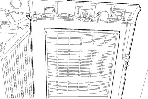
Slowly loosen the radiator cap (15). Disconnect the overflow hose (5) from the radiator neck.
NOTE: Refer to illustration on page 5.
STEP 6

If equipped with a heater, open the heater coolant valve.
STEP 7
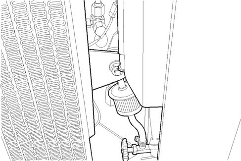
Install a hose on the drain valve (1) and drain the radiator into a clean container that holds approximately 17 litres (4.5 gallons).
STEP 8
If equipped with a heater, close the heater coolant valve (1).
Step 9
Step 12
BD07K011-01
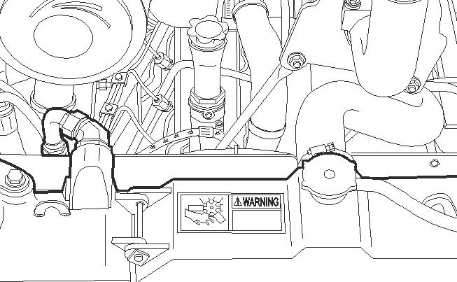
Loosen the clamp (1) on the upper radiator hose and remove the hose from the upper radiator connection.
Step 10
BD07K006-01
Remove the cap (1) from the hydraulic reservoir. Connect a vacuum pump to the hydraulic reservoir. Start the vacuum pump.
Step 13
BD07K006-01
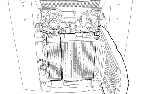
Loosen and remove the top (1) and bottom (2) mounting bolts on the radiator and oil cooler module. Use acceptable lifting equipment to support the radiator and oil cooler module after removal of the mounting bolts. Pull the radiator and oil cooler module away from the f an shroud until you can access the lower radiator hose clamp.
Step 11
BD07K006-01
Loosen and remove the upper (1) and lower (2) hoses from the oil cooler (3). Install plugs in the hoses and caps on the fitt ings to prevent loss of hydraulic oil from the hy draulic system. Stop the vacuum pump.
Step 14
BD07K006-01
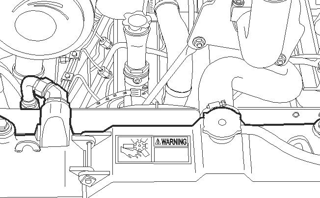
Loosen the clamp (4) on the lower radiator hose and remove the hose from the lower radiator connection.
NOTE: Refer to illustration on page 5.
BD07K006-01
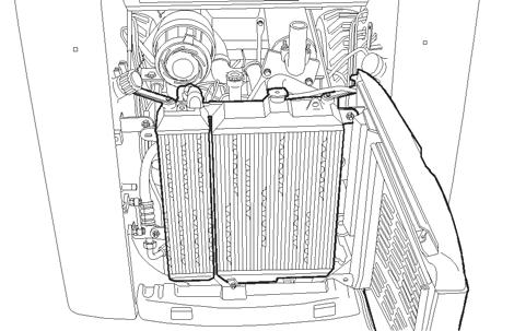
Remove the radiator and oil cooler module from the machine.
2000-6
Installation
STEP 15
Installation of the radiator is the reverse procedure of removal.
Step 16
After the radiator has been in stalled, fill the cooling system. See Section 1001 for the correct coolant mixture and quantity.
Step 17
Start and run the engine until it reaches operating temperature and check for any leaks. Stop the engine. After the engine has cooled, check the level of the cooling system and add coolant as required.
Engine
Removal
STEP 1
Remove the radiator from the machine.
STEP 2
Install plugs and caps on all disconnected hoses and fittings.
STEP 3
Tag all electrical connection for identification during assembly.
STEP 4
If equipped with a heater, disconnect the heater hoses (1) from the engine.
STEP 5
Lift the rear hood and open the rear access door.
STEP 6
BD07M168-01
Disconnect the electrical connectors from the rear tail lamps (1) on both sides of the rear access door. Disconnect the electrical connectors from the rear worklight (2). Disconnect t he electrical connectors from the backup alarm (3). Remove mounting hardware from the wiring harness (4) and remove the harness (4) from the rear access door.
STEP 7
Connect acceptable lifting equipment to the rear access door. Remove the pivot bolt (1) and lift the rear access door and remove from the machine.
STEP 8
STEP 11
BD07K006-01
1.CYLINDER PIVOT BOLT
Remove the nut from cylinder pivot bolt (1) on the hood end of the cylinder.
STEP 9
BD07K006-01
Remove the plastic clip (2) from the hood pivot shaft. Slide the hood to the left and remove the hood from the hood pivot shaft on both sides of the machine. Remove the hood from the machine.
STEP 10
Push the hood to the right hand side of the machine and remove the left hand side of the hood from the pivot pin. Remove the hood from the machine.
BD07K060-01
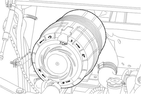
Loosen the clamp (1) on the outlet hose (2). Remove the outlet hose (2) from the intake and air filter assembly (3).
NOTE: Torque clamps (1) 3 to 4 Nm (25 to 35 pound-inches) during assembly.
STEP 12
Loosen and remove the mounting bolts and washers from the air filter housing mounting bracket.
STEP 13
Remove the air cleaner and bracket from the machine.
STEP 14
Remove the bolts and washers that fasten the front muffler support rods (5 and 8) and the rear muffler support rods (14 and 16) to the engine.
NOTE: Torque bolts 23 to 26 Nm (204 to 228 pound-inches) during assembly.
STEP 15
Loosen and remove the bolts and washers that fasten the muffler to the exhaust manifold.
NOTE: Torque the bolts 51 to 61 Nm (38 to 45 pound-feet) during assembly.
STEP 16
Remove the muffler from the engine.
STEP 17
Remove the cap screws (7), washers (8), fan blade (1), from the engine. Loosen and remove cap screws (4), washers (3) and spacer (2) from the engine.
Thank you very much for your reading. Please Click Here. Then Get COMPLETE MANUAL.NOWAITING

NOTE:
If there is no response to click on the link above, please download the PDF document first and then clickonit.
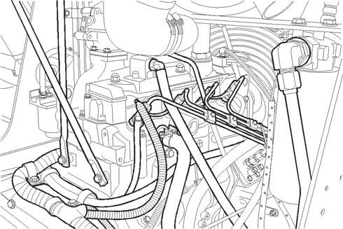
STEP 18
STEP 21
BD07M186-01
1.STARTER WIRES
2.WIRE HARNESS CLAMP
Disconnect the wires (1) fr om the starter and from the alternator (2). Loosen and remove the bolts and wire harness clamp (2) from the engine.
STEP 19
Loosen and remove the bolts that fastens the ground wires to the engine. Keep all ground wires together.
STEP 20
BD07M172-01
Remove the throttle linkage (1) from the fuel injection pump and the linkage (2) to the throttle control lever.
STEP 22
Disconnect the wire for the engine coolant temperature switch and the engine oil pressure switch.
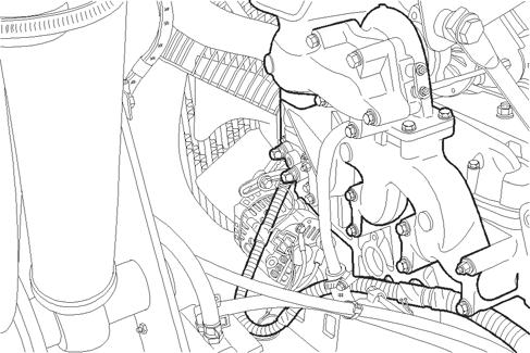
STEP 23
BD07M169-01
1.ALTERNATOR WIRES
Disconnect the wires from the alternator.
BD07M173-01
Disconnect the wire connecto r for the fuel injection pump solenoid.
STEP 24
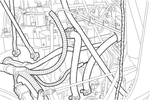
Loosen and remove the bolts that fasten the wire harness to the right side of the machine.
STEP 25
Move the all of the wiring harness out of the way.
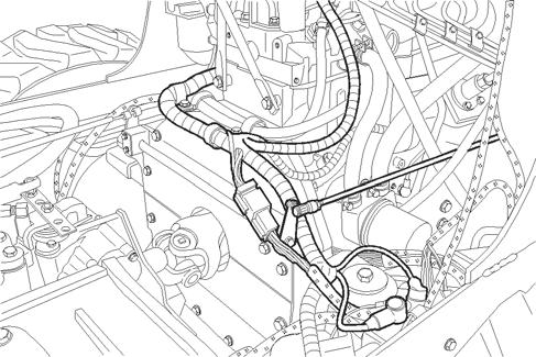
Step 26
Step 28
BD07M175-01
Close the fuel shut off valve.
Step 27
BD07M172-01
Loosen and remove the mounting bolts (1) which fasten the throttle linkage assembly (2) to the engine. Remove the linkage assembly (2) from the engine. Loosen and remove the mounting bolts (3) which fasten the cover (4) to the engine. Remove the cover (4).
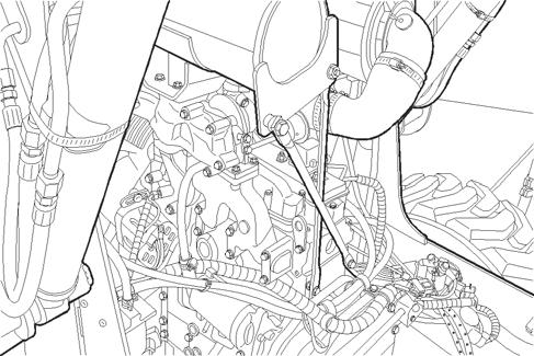
Step 29
BD07M171-01
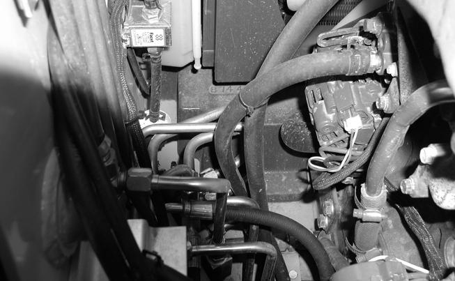
Disconnect the fuel lines (1) from the engine. Remove the bolts from the clamps (2) and remove the fuel lines (1) from the engine.
BD07M172-01
Loosen and remove the mounting bolts (1) which fasten the pump drive joint (2) to the flywheel (3). Remove the pump drive joint (2) from the flywheel (3).
NOTE: Tighten pump drive joint bolts to a torque of 94 to 106 Nm (68 to 78 pound-feet) during assembly.
STEP 30
STEP 36
Start and run the engine at low idle until the engine reaches operating temperature and check for any leaks. Stop the engine. After the engine has cooled, check the level of the coolant in the cooling system. Add coolant as required. Check the oil level in the engine crankcase. Add engine oil as required.
BD07M171-01
Connect acceptable lifting equipment to the engine lifting eyes at the front and rear of the engine.
STEP 31
Remove the bolt, washers, and nut from the rear engine mount (2).
NOTE: Torque the bolts 110 to 122 Nm (80 to 90 pound-feet) during assembly.
STEP 32
Remove the bolts, washers, and nut from the front engine mounts (1).
NOTE: Torque the bolts 110 to 122 Nm (80 to 90 pound-feet) during assembly.
NOTE: Refer to illustration on page 13.
STEP 33
Use lifting equipment and remove the engine from the chassis.
NOTE: During assembly apply Molykote GN to the pump drive joint splines before assembly.
Installation
STEP 34
Installation of the engine is the reverse procedure of removal.
STEP 35
After the engine and radiator have been installed, refill the engine cooling system. Refill the engine crankcase with engine oil. See Section 1001 for the correct type and quantity of engine coolant and engine oil.
