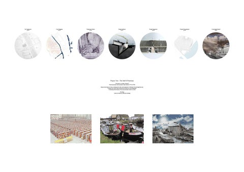
Site Exploration
Canal Mapping
Programme Studies
Design Synthesis
Design Progression
Proposal Development
Concluding Proposal
p21-29
p30-35
p36-42
p43-51
p52-64
p65-79
p80-93
Project Two - The Hull Of Hackney “All money is a matter of belief.” Words associated with economist Adam Smith (b.1723 d.1790) Based on the theme of value, exchange and worth, with exploration of Hackney Wick through this lens. Creating a site where ideas, materials and cultures are interchangeable. Considering what Hackney Wick and its broader context is worth. The Shop A place for material / physical exchange
Site Exploration Examinations of the Hackney Wick site, with specific interest in how the Hackney Cut canal intersects with site along, creating a physical boundary that separates it from the opposite bank, which is only accessible via a public footbridge also running along the site’s boundary. Also with observations of how the site and canal are inhabited and how this inhabitation may influence both programme and design. As identified from these studies, the prominence of narrowboats along the canal banks presents an opportunity for develop a programme to be centred around their significance.
1. Mossbourne Riverside Primary Academy fenced with planted, sloped yard facing site 2. Boats moored, mainly along East bank of canal, allowing boats to travel through the canal’s middle 3. Sloped landscape with footpaths facing site and trees planted equidistant down the slope 4. Rarely used and mostly empty parking and works yard of the warehouses neighbouring site 5. Rock climbing gym inside converted warehouses neighbouring site 6. Public lift and stairs to footbridge with accessibility for cyclists 7. Construction site currently in progress facing site 8. Art studios and restaurant with canal side seating 9. Food truck regularly parked in same spot 10. Various art studios and a design agency 11. Further car parking adjacent canal side buildings
12. View of site framed by trees across canal
13. View of site obscured by bridge on South side
14. Cyclists and joggers using canal footpath
15. Door and gate entrances to existing boathouse
16. Wallis Road facing facade of existing boathouse
17. Street art painted facade adjacent to site
18. Preserved facade of construction site building
Site Plan Identifying the key features of interest around the site while also examining the relative heights of structures and landscape through varying line weights, to acknowledge how the site may be obscured when looked at from certain perspectives.
0 North
2
5
10m 1:200
PRODUCED BY AN AUTODESK STUDENT VERSION 1. The Johnstone Boathouse building currently located on site, with design features such as English bond brickwork, brick fan window lintels and a tiled roof 2. Vehicle access to site, currently controlled via a metal gate and fencing beside the bridge and lift 3. Currently no physical barriers exist on site along the canal, due to access required for rowing boats
A
0 North
10
50m 1:2000
PRODUCED BY AN AUTODESK STUDENT VERSION
A
4. Covered external dining area for the neighbouring restaurant 5. Wooden balustrade along the canal side to prevent both accidental falling into the canal and access to the restaurant from the canal via boats 6. Windows from studios and apartments of the neighbouring buildings directly facing site, partially obscured by the public lift 7. External public access stairs and lift leading to the footbridge crossing the canal 8. Unused space under the footbridge, currently separated from site due to fencing preventing access 9. Maximum water depth along the canal is 1.2m (european-waterways.eu) 10. Sediment build up on the canal bed is very rarely dredged and, due to boats remaining stationary, is not often shifted by movement 11. Canal bed is a clay mix laid down during canal construction 12. Windows of the neighbouring warehouses partially facing site 13. Small wooden fencing along the canal bank to highlight the boundary rather than prevent access
Section AA A section through the canal, facing site, looking at how the existing boathouse building interacts with the canal and surrounding structures.
0
1
2.5m 1:50
PRODUCED BY AN AUTODESK STUDENT VERSION
B
0 North
10
50m 1:2000
PRODUCED BY AN AUTODESK STUDENT VERSION
B
1. The area is frequently inhabited by joggers, cyclists and dog walkers due to it being a long scenic pathway 2. Parent with children often move through the area to reach the school directly opposite site 3. The school opposite site is partially obscured by metal fences and planted with trees and bushes 4. Sloped landscape with direct and indirect footpaths facing site 5. Various types of boat are moored along the East bank, some semi permanently 6. Maximum water depth along the canal is 1.2m (european-waterways.eu) 7. Sediment build up on the canal bed is very rarely dredged and, due to boats remaining stationary, is not often shifted by movement 8. Canal bed is a clay mix laid down during canal construction 9. Street lamps along the footbridge provide the only artificial lighting on the canal near site 10. Temporary fencing in place for construction site 11. Gabions built for flood protection where the landscape has been artificially raised
Section BB Looking at the view across the canal from site, exploring how the view is mostly unobscured by any major structures and how it is inhabited by both people and boats.
0
1
2.5m 1:50
PRODUCED BY AN AUTODESK STUDENT VERSION
C
0 North
10
50m 1:2000
PRODUCED BY AN AUTODESK STUDENT VERSION
C
1. The area is frequently inhabited by joggers, cyclists and dog walkers due to it being a long scenic pathway 2. Boats moored along the canal banks are tied off with rope rather than any other sophisticated method, even with those there semi-permanently 3. The canal has no physical barriers to entry on either bank, allowing unimpeded access 4. Maximum water depth along the canal is 1.2m (european-waterways.eu) 5. Sediment build up on the canal bed is very rarely dredged and, due to boats remaining stationary, is not often shifted by movement 6. Canal bed is a clay mix laid down during canal construction 7. Access to path and restaurant’s canal side seating is restricted by metal fencing in place on the north side of the bridge - although nothing is currently built under the bridge 8. Existing building on site - Johnstone Boathouse 9. Studios and restaurant building behind site 10. Public access external lift and stairs to bridge
Section CC 0
1
2.5m
An examination how the site is situated on the canal, looking at how boats are moored and the clear view of site from across the canal. Additional Section DD in appendix, p94
1:50
1. Warehouse converted to rock climbing gym neighbouring the site, using the same access road 2. Metal gate of neighbouring property, providing access to seldom used parking and works yard 3. Existing building on site - Johnstone Boathouse - two storey detached brick building with windowed facades facing Wallis Road and the canal 4. Access road to warehouse and parking, currently lined with bollards preventing vehicle entry 5. Vehicle access gate to site, currently obstructed by bollards preventing large vehicle entry 6. External lift and stairs leading to public footbridge, with glass front facing facade 7. Windows of studios and apartment looking directly upon the site with visibility only partially obstructed by the lift and bridge 8. Relatively tall studio, apartment and restaurant building blocking direct sunlight at midday - also creating a relatively unaesthetic view from site 9. A food truck, serving hot and cold food and drinks, that is regularly parked adjacent to site 10. Additional car parking further down, opposite canal side buildings
11. View of site from further down Wallis Road
12. Point at which the boathouse meets neighbouring fencing and gate
13. Facade of boathouse directly facing Wallis Road
PRODUCED BY AN AUTODESK STUDENT VERSION
14. Inhabitation of stairs accessing the footbridge
0 North
10
50m 1:2000
PRODUCED BY AN AUTODESK STUDENT VERSION
p
15. The food truck regularly parked in the same spot
16. Painted facades of the buildings further down
View of Site from Willis Road - Three Point Perspective Identifying the site in context of how it can been seen when viewed from the approach of Willis Road, with particular interest in how the existing boathouse building is relatively unimposing compared to the surrounding site.
1 16 18 7 3 12
11 4 10 2 8 5
15
6
17 14
9 13
1. A multi purpose building taller than the existing boathouse on site, and with windows facing it, casting a shadow over it during at midday 2. A public footbridge with stair and lift access, located on the South border of the site 3. Construction sites currently under development facing the site, with several large cranes in use 4. Vehicle access to site via Wallis Road, often with cars parked on either side, possible restricting large and towed vehicle entry 5. Existing boathouse’s vehicle entry point, using the bridge as a barrier to public access 6. The existing boathouse’s canal facing facade falling into dereliction due to lack of maintenance 7. Boathouse design features including an overhanging roof, English bond pattern brickwork, white cladding borders, arrow-slit style window and a large roller door for canal access 8. A small storage structure on site detached from the boathouse 9. Unobstructed access to the canal, without any barriers or gates 10. Converted warehouses neighbouring site, with seldom use parking and works yard 11. Large wholesale supermarket separated from canal and surrounding properties with metal fencing and brick walls 12. Canal continuing North with few large structures in view but several bridges restricting boat height 13. Canal water appears relatively clear, with little sign of pollutants and rubbish on the surface 14. Boats predominantly moored on the canal’s East bank, allowing more space for boats to travel in either direction 15. Public benches and other inhabitation points facing opposite site with clear view across canal 16. Primary school located across canal from site with parents and children often traveling to and from 17. Declining landscape opposite canal with frequent inhabitation and unobstructed view of site 18. Construction in progress in view from site
Site Photo Collage Analysing how the current boathouse building located at the site appears in the surrounding context of the buildings and landscapes on the Hackney Cut canal.
Gabion flood defence barriers located at several points along the canal - consisting of simple mesh metal box frames filled with rocks to protect landscape behind from erosion caused by flooding
Metal wire fencing under footbridge on opposite side of canal to site - preventing public access while allowing light and water to pass through to sustain the shrubbery and vegetation within
Metal wire fencing of parking and works yard neighbouring site - preventing unauthorised vehicle and public access while minimising obstruction of the view of the canal and landscape beyond
Metal barrier partially along the footbridge staircase - providing a similar aesthetic to the bridge by hiding the bare brick external wall of the building behind and the gap between them
Metal fencing of existing gate access to site - heavily obscuring the view within while still allowing some perception of what is beyond if close enough to see through
A large rope net swing located in a play area further North along the Canal - reminiscent of the rope work used in traditional wooden ships, providing a flexible but strong support
Metal fencing panels along the roadside of the school opposite site - consisting of many identical holes on corrugated panels, creating a wave like pattern that partially obscures what is beyond
Metal fencing panels along the roadside of the school opposite site - designed to allow light and sound to travel through while having holes small enough to prevent objects or people from being able to enter
Equidistant metal bar balustrade along footbridge - providing safety with a barrier against falling while not obstructing the view along the canal to heavily so the bridge does not feel too sheltered and isolated from the landscape
Mesh Transparencies A study of various mesh materials of different purposes found around the site that vary in how much light can pass through and how public access is or is not obstructed.
Using the site model to explore a panning aerial view of site along the canal, starting along the south side and arching around to the opposing bank and north side. Seeing how site is view from the perspectives of boat canal path users.
A panning aerial view of site from the street side to better understand how it sits in the local landscape of surrounding buildings and structures, showing how it is overshadowed by the flat block/restaurant on the south side.
Views approaching and moving past site along the road to see how the view of site is narrowed into perspectives between the two neighbouring buildings and how this emphasises it as being situated in a corner.
Site Model A model of the immediate site, including the canal and opposite bank, of 1.1m x 0.9m at 1:100 scale. Contributed to by: Myself, Dardan Zenuni, Cat Lum, Colette Roberts, Gabriela Czaplinska, Gargee Nike, Joel Maquera, Nicole Santos and Miles Barton-Black
PRODUCED BY AN AUTODESK STUDENT VERSION
PRODUCED BY AN AUTODESK STUDENT VERSION
PRODUCED BY AN AUTODESK STUDENT VERSION
PRODUCED BY AN AUTODESK STUDENT VERSION
PRODUCED BY AN AUTODESK STUDENT VERSION
PRODUCED BY AN AUTODESK STUDENT VERSION
PRODUCED BY AN AUTODESK STUDENT VERSION
PRODUCED BY AN AUTODESK STUDENT VERSION
Canal Mapping Using mapping of canals and waterways locally and across the UK, after identifying the Hackney Cut canal as a significant feature of the site context. Intended to gain more depth in understanding the uses, extents and inhabitation of canals so as to adequately consider the implications of a design proposal bordering a canal, while finding further observations of their idiosyncracies As previously identified, narrowboats are a major feature of inhabitation along canals so are of particular interest in further research explorations.
Canals and Rivers 1. Hackney Cut, River Lee Navigation 2. River Lee Navigation 3. River Thames 4. Regent’s Canal 5. Paddington Arm 6. River Stort 7. Slough Arm 8. Grand Union Canal 9. Chelmer & Blackwater 10. River Medway 11. River Stour 12. River Wey 13. Basingstoke Canal 14. Kennet & Anon Canal 15. Bridgewater & Taunton Canal 16. Grand Western Canal 17. Oxford Canal 18. Aylesbury Arm 19. River Arun 20. River Adur 21. River Nene 22. Middle Level
94
23. Great Ouse 24. River Cam 25. River Lark 26. River Little Ouse 27. River Welland 28. River Glen 29. River Wensurn
91 UK Watercraft Ownership
30. River Yare 31. River Chet
62
32. River Waveney 92
90
77
33. River Bure 93
80
34. River Thurne 61
85
89
78
36. Gloucester & Sharpness Canal
90
79
37. River Severn
85
84
81
35. Monmouthshire & Brecon Canal
86
83
38. River Avon
87
39. South Stratford Canal
60 73
77 76
PRODUCED BY AN AUTODESK STUDENT VERSION
55
58
53 72
56
65 72
70
63
66 57
53
55 64
67
52
67
53 54
68 69
53 63
28
53
27
34
43
21 47
69
33
51 22
48
33
23 29
45 46 44
43
37
47
32
49
25
21 23
8 41
30
26
22
17
40
42
30 31
50
8 41
34
24
39
43. Staffordshire & Worcestershire Canal 44. Stourbridge Canal; Dudley Canal No1; Dudley Canal No2 45. New Mainline Canal; Old Mainline Canal; Tame Valley Canal; Wyrley & Essington Canal; Rushall Canal 46. Birmingham & Fazeley Canal 47. Coventry Canal 48. Ashby Canal 49. Leicester Line 50. Market Harborough Arm 51. River Stour 52. Erewash Canal 53. Trent & Mersey Canal 54. Upper Trent 55. River Trent 56. Fossdyke Canal 57. River Witham 58. Chesterfield Canal 59. River Idle 60. River Ancholme 61. River Hull
8
62. Driffield 63. Shropshire Union Canal
38
Believes that spending time by water improves mental health and wellbeing.
64. Caldon Canal
37 17
8
65. Macclesfield Canal
11
66. Middlewich Branch
Encourages communities to volunteer and work together in improving canal and river spaces.
11
67. Llangollen Canal
37
35 Projects include social and recreational developments, nature protection and heritage preservation.
18
36
68. Prees Branch
6
69. Montgomery Canal
9
70. River Dee
Responsible for 2980 bridges, 1580 locks and 335 aqueducts.
8
3
2
71. Manchester Ship Canal 72. Weaver
5
7
4
1
73. Bridgewater Canal 74. Peak Forest Canal
3
3
75. Ashton Canal
14
76. Leigh Branch
10
77. Leeds & Liverpool Canal
13
78. Rufford Branch
12
79. Ribble Link 80. Lancaster Canal 81. Rochdale Canal
PRODUCED BY AN AUTODESK STUDENT VER 82. Huddersfield Narrow Canal
15
83. Huddersfield Broad Canal 84. Calder & Hebble 16
19
20
85. Aire & Calder Main Line 86. New Junction Canal 87. Stainforth & Keadby Canal 88. Sheffield & South Yorkshire 89. River Aire
UK Canal Networks Being located on the Hackney Cut of the River Lee Navigation canal, the site is connected to a vast expanse of canal networks linking North and South England. This presents the opportunity to utilise this network in a potential programme to be determined.
ODUCED BY AN AUTODESK STUDENT VERSION
A charity organisation responsible for maintenance, preservation and renovation of 2000 miles of waterways in the UK, including the Hackney Cut canal.
74
73
42. Droitwich Barge Canal
PRODUCED BY AN AUTODESK STUDENT VERSION
*statistica.com
41. Worcestershire & Birmingham Canal
59
75
71
71
40. North Stratford Canal
88
82
90. River Ouse 91. Ure 92. River Derwent 93. Pocklington Canal 94. Tees
Key Sea Land Non-CRT Canal/River CRT Canal/River Site
0 North
10000
50000m 1:1250000
PRODUCED BY AN AUTODESK STUDENT VERSION
PRODUCED BY AN AUTODESK STUDENT VERSION
1:200000 Map of London Waterways 6 5
27 30
1
43
39
44
1
26
24
38
4
40
3
28 29 25
41
2
23
48
42
28
31
44
43
22
45
45
28
46
39
7
51
14
49
15 18
13 16
47
19
52
50
7 17 River Thames
2. Dagenham Brook 3. East & West Warwick Reservoirs 4. Walthamstow Reservoirs 5. Low & High Maynard Reservoirs 6. Lockwood Reservoir 7. Regent’s Canal 8. Limehouse Cut 9. Limehouse Basin 10. Canary Wharf Docks 11. Millwall Docks 12. Royal Docks 13. City Road & Wenlock Basins 14. Islington Canal Tunnel 15. London Canal Museum 16. Maida Hill Tunnel 17. Paddington Basin 18. Paddington Branch 19. Regent’s Park
1
8
1. River Lee Navigation
48
9
53
20. Hyde Park
12 10
21. St James’s Park
20
22. West Reservoir
21
23. East Reservoir
11
54
24. New River 25. Hampstead Heath Pools
CRT London Boats Survey 2016
26. Mutton Brook
Results from a 2016 survey with results from 1323 London boat owners: -
58% use their boat as a main home 69% currently live on a London based boat 50% living on boats for affordability 50% living on boats for three years or less 70% own their boat outright 33% have experienced mechanical issues in past 12 months preventing them from moving - 45% interested in more readily available mooring
27. Dollis Brook
32
35
28. River Brent 29. Brent Reservoir
56
58
37 33
34
30. Silk Stream 31. Wealdstone Brook
55
57
59
32. Deptford Creek
36
33. Ravensbourne River 34. River Quaggy 35. Battersea Park
38,000 narrowboats are currently registed in the UK, with one quarter of these used as homes.
36. River Wandle 37. Beverley Brook PRODUCED BY AN AUTODESK STUDENT VERSION
Since 2012 London boat ownership has increased 57%
38. Hollow Pond 39. River Roding 40. Wanstead Park 41. Alders Brook 42. Heronry & Perch Ponds 43. River Rom 44. The Ravensbourne 45. The Chase Nature Reserve
Harry Beck Style Map of London Waterways
46. Beam River
to Birmingham & Nottingham
47. Dagenham Breach
to Hertford & Bishop’s Stortford
PRODUCED BY AN AUTODESK STUDENT VERSION
An organisation, founded 1946, dedicated to restoring 6500 miles of UK canals and rivers for general use.
48. River Ingrebourne
PRODUCED PRODUCED BY BY AN AN A A
49. Berwick Pond Provides funding for restoration projects and training for volunteers to improve local waterways.
Watford
West Hampstead
Rackmansworth Harefield
Currently undertaking restoration efforts for canals and waterways across the UK, aiming to provide economic, social and environment benefits to affected areas.
Edmonton
51. Russell’s Lake
Tottenham Hale
52. Aveley Lakes
Kilburn Kentish Town
Uxbridge Slough
50. Rainham Creek
Hampstead Hill
53. Kennington Park
Maida Vale
Clapton
54. Mardyke
Langley
55. Boating Pond
Cowley Peachey Southall
Acton
Little Venice
Regent’s Park
Camden Lock
King’s Cross
Ladbroke Grove
Bull’s Bridge
Haggerston
Paddington
Euston Hackney Wick Mount Pleasant
Serpentine
Richmond Twickenham
Kew
Chiswick Mortlake
Chelsea Putney
Newgate City Airport
Weybridge
River Welbrooke
Vauxhall Battersea
Royal Victoria Dock
Limehouse Blackfriars
Southwark
Isle of Dogs
River Effra Camberwell
Teddington to Reading & Oxford
Hackney
Bank Victoria (Grosvenor Basin)
River Fleet Brentford
Three Mills
Moorfields
Farringdon Sloane Square
Brixton Henne Hill
Windsor
New Cross Fleet
Woodham Deptford
Ash Norwood
Guildford Godalming
to Gravesend & Chatham
58. Ellingham 59. Dartford
London Canal Networks Lee Navigation Bow Back Rivers River Thames Docklands Regent’s Canal Grand Union Canal River Wey & Basingstoke Canal Croydon & Grand Surrey Canals Lost Rivers
Croydon
London Waterway Mapping Observing how the waterways of London are mostly integrated into a network, historically used for transport of goods, but presently under utilised. Also seeing how significant locations of the city can be simplified in relation to waterways with mapping in the style of the TFL.
0
PRODUCED BY AN AUTODESK STUDENT VERSION
Greywell
Woking
Greenwich
57. River Cray
STUDENT VERSION VERSION STUDENT
Basingstoke
City Mills
Bow
PRODUCED BY AN AUTODESK STUDENT VERSION
PRODUCED BY AN AUTODESK STUDENT VERSION
River Westbourne
Hertwell Locks
Stratford
City Road Basin
PRODUCED PRODUCEDBY BYAN ANAUTODESK AUTODESKSTUDENT STUDENTVERSION VERSION
56. River Darent Carpenters Road
North
2000
5000m 1:200000
PRODUCED BY AN AUTODESK STUDENT VERSION
Dagenham Brook Leyton Grange Estate
Cathall Hackney Marshes
PRODUCED BY AN AUTODESK STUDENT VER 3
Kingsland Homerton
Stratford
1 Hackney Wick Queen Elizabeth Olympic Park
West Ham
2
4 South Hackney
London Stadium
6
Fish Island 7
Victoria Park Old Ford
PRODUCED BY AN AUTODESK STUDENT VERSION
Chobam Manor
3. River Lee 4. Hertford Union Canal 5. Regent’s Canal 6. Water Works River 7. City Mill River 8. Pudding Mill River
Key Non-CRT Canal/River CRT Canal/River Site Structures Marina Lock
5 3 Bow
8
Globe Town Bromley By Bow
3
PRODUCED BY AN AUTODESK STUDENT VERSION
PRODUCED PRODUCED BYBY ANAN AUTODESK AUTODESK STUDENT STUDENT VERSION VERSION
2. River Lee Navigation
PRODUCED BY AN AUTODESK STUDENT VERSION PRODUCED BY AN AUTODESK STUDENT VERSION
According to yearly trends in demand, narrowboats are often more sought after in anticipation of summer when they can more often be used. This presents an opportunity for a programme in which narrowboats are constructed and stockpilled through the year, in time to be sold during peak demand in Spring.
1. Hackney Cut
CED BY AN AUTODESK STUDENT VERSION
Due to increasing costs of living in London, demand for narrowboats is increasing due to their use as alternative housing. This is particularly applicable in Hackney which is currently undergoing rapid redevelopment and gentrification, with rising property costs for residents who are unable to relocate locally.
2
PRODUCED BY AN AUTODESK STUDENT VERSION
PRODUCED BY AN AUTODESK STUDENT VERSION
Lower Clapton
Water Feature Mapping
Identifying of water features of significance in the contexts of Hackney and the surrounding area, to understand how the various canals, rivers and reservoirs feed into one another to create a series of interconnected connected and isolated waterways.
0 North
100
500m 1:15000
PRODUCED BY AN AUTODESK STUDENT VERSION 2
PRODUCED BY AN AUTODESK STUDENT VERSION
A1
y rsit
PRODUCED BY AN AUTODESK STUDENT VERSION PRODUCED BY AN AUTODESK STUDENT VERSION
e
iv Un h g ou on bor ond h g L ou
A12 L
PRODUCED BY AN AUTODESK STUDENT VERSION PRODUCED BY AN AUTODESK STUDENT VERSION
Here East Technology Park
r ve
Ri n tio
iga av
eN
Le
Canal Key Canal Lock
River Le
Boat Mooring
my
ade
Ac
e
ry
ma
Pri
Canal Access Point
Pump Out
Water Point
Hack
Water Current Direction
Copper Box Arena
ney
is Road
Cut
Wall
Cana
Hackney Wick
Flood Hazard
l Low
EC
Moderate
A1
2
2
A1
Queen Elizabeth Olympic Park
A12
l
na
a nC
io
r
fo
rt He
n dU
A12
PRODUCED PRODUCED PRODUCED PRODUCED BY PRODUCED AN BYAUTODESK PRODUCED AN BYAUTODESK BY AN AN BY AUTODESK AN STUDENT AUTODESK BYAUTODESK AN STUDENT AUTODESK STUDENT VERSION STUDENT VERSION STUDENT VERSION STUDENT VERSION VERSION VERSION
te
sR
ros Significant
tation
kS Hackney Wic
n nio o3 U N rd fo Lock t r He wer Lo
Hackney Cut Amenities and Flood Risk An examination of the amenities and features available to boat users along the Hackney Cut branch of the River Lee Navigation. Also looking at the risk of flooding caused by surface run off from precipitation, which is managed by controlled canal water levels.
0 North
50000 1:2500
100000m
8
1
2
3
4
6
7
8 6
on ati vig ion Na gat ee avi rL N ve ee Ri r L ve Ri
5
PRODUCED PRODUCED BY AN BYAUTODESK AN AUTODESK STUDENT STUDENT VERSION VERSION
rf
ha
W rf
ha
W
ut yC ne ut ck C Ha ney ck Ha
las
At
las
At
4
PRODUCED BY AN AUTODESK STUDENT VERSION
Sediment Clay
Natural Mud / Soil
2
First built in 1769 as a means of providing a more direct and faster waterway for cargo boats to travel along the River Lee. As with all canals it also is used for flood control as there is no constant water current flow and water levels are controlled with locks at either end. Due to the design and construction methods of the time, the canal is dug square and consists of laid clay floor and walls, on which wood cladding panels are secured. According to local residents, the canal have not been dredged in several years so a layer of sediment is covering the canal bed.
1
OIA RL ROAD S SD I L L L A A W W
PRODUCED BY AN AUTODESK STUDENT VERSION
Wood Panel Cladding
PRODUCED BY AN AUTODESK STUDENT VERSION
PRODUCED BY AN AUTODESK STUDENT VERSION
1:50 Hackney Cut Canal Section
3
PRODUCED BY AN AUTODESK STUDENT VERSION
5
PRODUCED BY AN AUTODESK STUDENT VERSION
7
Canal Journey Serial Vision
Exploring a potential canal route taken by boat along the Hertford Union Canal and Hackney Cut to reach site, to acknowledge how the canals intersect with the bridges, locks and landscapes enclosing them.
0 North
25
50m 1:1250
Programme Studies Researching into a programme centred around the construction of narrowboats to be stored and launched onto the Hackney Cut canal. Looking specifically into the work activities involved with the building of narrowboats and the various stages of progression they go through to reach completion. The understanding gained in these studies is fundamental in sufficiently accommodating these programme activities into later design proposals.
1 2 3
6
10
11
9
4 5
12
8
7 Although predominantly narrowboats moored along the east bank of the canal, other boats of various design and purpose are also present. However these other boats are more frequent in moving compared whereas the narrowboats are often moored permanently, due to their use as constant housing.
Also of note is the fact that, while given permits to moor along the canal, none of the moorings here are intended to be anything more than temporary for tying off resting boats. This is evidence of the lack of consideration of waterways to be provided facilities for security and hospitality.
1. Narrowboat: Wide beam; Cruiser stern; Leisure and dining 2. Narrowboat: Wide beam; Traditional stern; Living and leisure 3. Narrowboat: Narrow beam; Cruiser stern; Leisure 4. Narrowboat: Narrow beam; Cruiser stern; Living 5. Cruiser boat: Leisure 6. Narrowboat: Wide beam; Traditional stern; Living 7. Work boat: Cargo and leisure 8. Narrowboat: Narrow beam; Cruiser stern; Living 9. Narrowboat: Wide beam; Semi-traditional stern; Living 10. Narrowboat: Narrow beam; Cruiser stern; Living 11. Sail boat: Leisure 12. Narrowboat: Wide beam; Cruiser stern; Dining and accommodation
Hackney Cut Narrowboats An examination of how the Hackney Cut canal is inhabited, particularly in regards to the various types of boats that are moored along its banks. Specifically noting that these are predominantly narrowboats moored along the east bank.
Beam Types
Narrowboat Lengths and Uses
Narrow Beam Maximum width - 2.1m Average width - 1.8m Wide Beam Minimum width - 2.1m Average width - 3.5m
Maximum length - 21m Dining, Accommodation, Leisure, Cargo
Average length - 12.5m Living, Leisure, Cargo
Minimum length - 6m Leisure, Cargo
Presumed Sections Through Living Use Narrowboat Section AA
Section BB
B
B
River Lee Navigation Boat Restrictions: Maximum length - 25.8m Maximum width - 4.7m Maximum draught - 1.6m Maximum headroom - 2.18m Roof Storage Bars
Roof Storage Bars Steering and Back Deck
Front Deck
Engine Types: Air cooled - relying on a constant flow of air Keel cooled - water flow contained in tank on stern Raw water cooled - pumps canal water around engine
Toilet Cubical
Storage Kitchen Space
Kitchen Space Dining Space
Heating Types: Solid fuel stove - burning coal or wood fuel Gas central heating - burning fuel from gas canister Diesel fired heating - burning fuel manually pumped in
Side Storage Spaces
Tyre Buoy
Seating and Pullout Bed
50-75mm Thick Steel Body
Toilet Types: Pump out - emptying into holding tank to be pumped out at marina or elsan point on canal Cassette - emptying into cartridge to later be lifted out and emptied at marina or elsan point on canal
Rudder
Engine Space
50-75mm Thick Steel Body
B
B
Stern Typology - Two Point Perspectives Traditional
Semi-Traditional
Cruiser
Dutch Barge Style
Minimising external deck space to increase internal space. Typically used for living and cargo boats where external space is less important.
Large, uncovered deck spaces with seating on one or both sides, enclosed with walls. Mostly used for recreational and leisure boats to provide more scenic passenger cruising.
Large open space decks with balustrade enclosure and no seating. An alternative for recreational and leisure boats to enable social gathering on outer deck.
Based on Dutch Barges but narrower in width to fit UK canals. Large unenclosed outer decks with sloping appearance. Traditionally used for cargo boats but also available for leisure and living boats.
Narrowboat Typologies Analysing the distinctions between the different characteristics and definitions of canal narrowboats to identify the idiosyncrasies of these typologies and how these may later be incorporated into a programme.
0
1
2.5m 1:50
1. A base plate is cut to a predetermined shape and size out of 10mm thick sheet steel - sometimes welded in layers of two or three for larger boats.
2. Support beams are spot welded at regular intervals across the base plate and the font and rear door frames are cut from 5mm steel sheets and erected.
3. 6mm thick steel sheets are cut and spot welded into place along the sides to create the hull of the boat - strengthened with metal support beam ribs.
4. The stern and bow are built up further with walls and flooring spot welded into place. Any excess base plate protruding is trimmed with plasma cutters.
5. The cabin walls are cut to size, with window and vent holes, then welded in place on the boat shell, supported by metal props.
80 x 80mm Steel Square Beams 80 x 80mm Steel Square Beams
Circular Cut Window Holes
Metal Workshop 6 Weeks
10mm Steel Base Plate
5mm Steel Sheet Cabin Walls
6mm Steel Sheet Hull
5mm Steel Sheet Panels
6. The cabin ceiling is assembled separately then held in place with metal props while being spot welded to the finish the shell of the boat.
7. Rubbing strakes are welded along the front, rear and sides of the hull to protect from impact damage and scrapping when in the water.
8. The engine is moved into position in the engine bay which is then covered and sealed, with the tiller or steering wheel also assembled in place.
9. Deck rails and small metal parts are tack welded onto the shell then all exposed seams are welded again to be made water tight, ground and polished.
PRODUCED BY AN AUTODESK STUDENT VERSION
PRODUCED BY AN AUTODESK STUDENT VERSION
Engine Bay
10. With metal work completed, the interior panels are spray foam insulated and left to dry - rather than assembling a layer of solid sheet insulation.
Steel Roof Bars
Ventilation Chimney
Spray Foam Insulation
4mm Steel Sheet Roof
Steel Hand Rails
Small Steel Components Steel Rubbing Strakes
Covered Engine Bay Steering Tiller Engine
Steel Rubbing Strakes
11. Wooden panels of a predetermined type are cut to size and shape then assembled to the shell with various metal fittings and some glue.
12. Further wooden panels are cut from 30mm thick sheets and are assembled to become the interior cabin walls, doorways and furniture shells.
13. Additional furnishings of the customer’s specification are assembled within the cabin. Wiring and electrical fittings are done where necessary.
14. Final furnishings and doors are assembled before the wooden interior is sanded and detailed then painted by hand or with spray paint.
15. The boat is completed with the exterior spray painted, sanded and repainted then left to dry. A final inspection is undergone to identify any faults.
Fixed Wooden Base Seating
Wooden Frames for Kitchen Furnishings and Appliances
Furniture Coverings Appliances Installation
Wooden Panel Interior Wall
Wooden Doors
PRODUCED BY AN AUTODESK STUDENT VERSION
Wooden Panel Flooring
Painting Workshop 1 Week
Carpentry Workshop 3-4 Weeks
Adjustable Furnishings
Narrowboat Construction Process An examination of the various stages undergone in building a narrowboat, with attention to the materials processes used and time taken at each workshop location.
0
1
2
5m 1:100
Metal Workshop
Plasma Cutting
Spot, Tack and Watertight Welding
Grinding and Polishing
Spray Foam Insulation
Standard modular metal sheets and bars required to be changed in size and shape are done so via hand held plasma cutters. These are also used when trimming excess metal material that is protruding after bing assembled. Protective visors and gloves are worn and constant inspection is done to ensure dimensions are to specification.
Steel sheets and bars that comprise the shell of the boat are first spot welded together to be fixed in place, then later given a water-tight weld to ensure buoyancy. Rubbing strakes and other small steel components are also welded on with spot weld and tack welds. All welding is done by hand due to the material size.
After assembly, welding seams, scrapes and rough edges of the steel shell are ground down to a smooth, flat surface finish. Polish is applied to the steel to improve the finish quality, with more coats applied to material that is not to be painted and is more visible.
Rather than installing sheet insulation, foam insulation is sprayed across the interior walls, floor and ceiling before they are covered by any additional panelling. Full protective suits with breathing apparatus are required and the space must be well ventilated. After application, the foam drying is quickened with a space heater.
Carpentry Workshop
Painting Workshop
Carpentry and Interior Construction
Electrical and Appliance Fitting
Painting and Fine Sanding
Modular timber material is cut to size, using fixed and potable machinery and tools, to the required dimensions for the interior cabin walls and flooring. The timber panels, boards and beams are then fixed in place with wood glue and/or metal fittings, depending on requirements to be reconfigurable.
First and second fix wiring id done for the electrics of the boat, including for lighting, heating and various appliances. The engine, fuel tanks and various mechanical parts are fitted into place so as to remain accessible in case of faults during the boat’s life that require repairs.
Larger surfaces of the boat that require painting are done so with spray painting, in a contained area, whereas smaller areas are done by hand with paint brushes and rollers. The shell exterior is given multiple coats, with fine sanding done in between coats so as to provide a constant smooth surface finish.
Narrowboat Construction Activities Identification and description of the various activities that are performed during the narrowboat construction process.
Individual Metal Components
Palletised Material Arrangement
Narrowboat Assembly with Components (Section)
14000mm x 3000mm x 210mm Weight: 15,726kg
PRODUCED BY AN AUTODESK STUDENT VERSION PRODUCED BY AN AUTODESK STUDENT VERSION PRODUCED BY AN AUTODESK STUDENT VERSION
Aluminium Poles O50mm x 2300mm Weight: 3kg Qty: 2 Use: Roof bars
Aluminium Poles O50mm x 4400mm Weight: 6kg Qty: 2 Use: Roof bars
Aluminium Poles O70mm x 1500mm Weight: 2.5kg Qty: 2 Use: Coupling mechanism
Mild Steel Bars 80mm x 80mm x 2700mm Weight: 20kg Qty: 140 Use: Structural ribs
Mild Steel Sheets 5mm x 2500mm x 2500mm Weight: 245kg Qty: 3 Use: Hull and cabin components
Mild Steel Sheets 5mm x 2500mm x 1500mm Weight: 147kg Qty: 2 Use: Hull and cabin components
Mild Steel Bars 50mm x 50mm x 2700mm Weight: 13kg Qty: 10 Use: Step structure support
Mild Steel Bars 80mm x 80mm x 6750mm Weight: 51kg Qty: 4 Use: External strakes
Timber and Glass Material Components
Individual Timber and Glass Components
Palletised Material Arrangement
Narrowboat Assembly with Components (Section)
13600mm x 2200mm x 105mm Weight: 1237kg
Plywood Panels 15mm x 13600mm x 2200mm Weight: 278kg Qty: 1 Use: Flooring and steps
Plywood Panels 15mm x 13000mm x 2000mm Weight: 242kg Qty: 2 Use: Interior cabin walls
Douglas Fir Timber Blocks 300mm x 600mm x 50mm Weight: 5kg Qty: 10 Use: Detachable walls
Laminated Glass Panes 1300mm x 1000mm Weight: 19.5kg Qty: 2 Use: Roof windows
Laminated Glass Pane 1300mm x 750mm Weight: 13.5kg Qty: 1 Use: Driver front window
Plywood Panels 15mm x 1300mm x 500mm Weight: 60.5kg Qty: 2 Use: Angled ceiling
Plywood Panels 15mm x 2500mm x 2200mm Weight: 51kg Qty: 1 Use: Various interior cladding
Plywood Panels 15mm x 2200mm x 2000mm Weight: 41kg Qty: 4 Use: Various interior cladding
Narrowboat Materials Identifying and quantifying the materials required to build the shell of a narrowboat built at the workshop, allowing more accurate consideration for material storage space and condition requirements.
Laminated Glass Panes 1800mm x 450mm Weight: 12kg Qty: 2 Use: Driver side windows
0
1
10
20m 1:100
PRODUCED BY AN AUTODESK STUDENT VERSION
PRODUCED BY VERSION AN AUTODESK STUDENT VERSION PRODUCED BY AN AUTODESK STUDENT
Mild Steel Sheets 5mm x 14000mm x 3000mm Weight: 1648.5kg Qty: 3 Use: Hull and cabin walls and roof
PRODUCED BY AN AUTODESK STUDENT VERSION
PRODUCED BY AN AUTODESK STUDENT VERSION
Mild Steel Sheets 10mm x 14000mm x 3000mm Weight: 3297kg Qty: 2 Use: Baseplate layers
PRODUCED AN AUTODESK STUDENT VERSION PRODUCED BY AN AUTODESK STUDENT BY VERSION
PRODUCED BY AN AUTODESK STUDENT VERSION
BY AN STUDENT AUTODESK STUDENT VERSION PRODUCED PRODUCED BY AN AUTODESK VERSION PRODUCED BY AN AUTODESK STUDENT VERSION
Metal Material Components
Metal Cutting
Eq
Spray Painting/Insulation
ui
n
o ati
il
t en /V
Welding
pm
en
tM
ob
ili
ow irfl
ty
A
red
i equ
Spa ce R
tR
equ i
red
h Lig Relative Condition Extent
Sound Pollution
PRODUCED BY AN AUTODESK STUDENT VERSION
Carpentry
Sanding/Grinding
Installation
a. Baseplate sheets are cut to shape and size b. Hull panels are cut to shape and size c. Square bars are welded to baseplate and hull panels d. Hull panels are assembled and welded to base plate e. Cabin walls and roof are cut to shape and size f. Cabin walls and roof are assembled and welded to hull g. Rubbing strakes are welded along the sides of the hull and cabin exterior h. Roof railing and additional components are welded to the narrowboat shell i. Welds and surfaces are ground and polished j. Shell interior is sprayed with foam insulation and left to dry k. Floor panels are cut to shape and size l. Floor panels are assembled to cabin floor m. Engine and components are installed n. Interior wall and ceiling cladding cut to size o. Interior wall and ceiling cladding assembled p. Electrical fittings installed q. Gas and plumbing fittings installed r. Additional components cut to size and assembled s. Interior is sanded and prepared for painting t. Spray painting of narrowboat interior (multiple coats) u. Exterior is sanded and prepared for painting v. Spray painting of narrowboat exterior (multiple coats) w. Hand painting of details and final inspection
a
b
c
d
e
Day 0
f
g
h
i
j
k
12l
m
n
o
Day 25 Metal Work
An approximate timeline of the activities performed during the construction of a narrowboat to explore how the workshop would accommodate different activity typologies, and also identifying the relative requirements/conditions for each of these typologies.
q
r
s
t
u
Day 40 Carpentry and Installation
Workshop Activities Timeline and Requirements/Conditions
p
v
w Day 47
Painting
Design Synthesis Preliminary designing of mechanism focused concepts for the accommodation of narrowboats on site, in attempts to overcome the conflict of size requirements imposed by the narrowboats and of site restrictions. These concepts are developed along side examinations of unique precedents that developed intriguing solutions to various situations posed by canal inhabitations. Although not directly designing for the entire programme at this stage, these early experiments provided better understanding of the realistic extents of designing for narrowboats on this site.
1:200 Plan
4
4
2
Lock Chamber
1
River Lee
River Lee Navigation 3
Lower Level
Upper Level
Lock Chamber
A
A
Public Footbridge
4
1:200 Section AA
3
5
6 7 8
13
PRODUCED BY AN AUTODESK STUDENT VERSION
12
10
9
0 North
100
250m 1:10000
PRODUCED BY AN AUTODESK STUDENT VERSION
River Lee Navigation
11
1. Lower lock gate - open 2. Upper lock gate - closed 3. Lock control room operated by a lock keeper 4. Designated mooring spots outside of the lock 5. Lower lock gate - closed 6. Upper lock gate - closed 7. Water level in lock chamber raised and lowered to allow passage of boats between upper and lower levels 8. Upper level water intakes 9. Filling valve - open 10. Water supply to and from lock chamber via water current controlled with valves on both sides 11. Emptying valve - closed 12. Lower level water release 13. Maintenance ladder built into lock chamber wall
Old Ford Lock No19 A study of the dual locks marking the start of the River Lee Navigation, looking at the mechanism of flooding the lock chambers to allow boats to move between higher and lower water levels, while also controlling water current.
0 North
1
10
20m 1:100
PRODUCED BY AN AUTODESK STUDENT VERSION
Old Ford Lock No19 - flooding mechanism
Lock Concept One - Section
Lock Concept Two - Section
Above ground water pipe
Above ground water pipes
L0
Garage, B29 - subterranean single vehicle storage
Pipe support columns
Pipe support columns Water release
L0 Workshop
Canal
1.b
Accessing boat storage chambers
Gate motors
Gate motors
2.b
2.d
1.a Water intake from the canal 1.b Filling valve opened and water reaches canal level
Rotary gate mechanism
1.c Gates opened to allow boat access Boat storage chamber
Flood chamber
1.d Filling valve closed; emptying valve opened
Boat storage chamber
1.e Water pumped above ground
L-1 1.g
Water intake and release pipes 1.b 2.b Water valve
1.f Water released into canal
Accessing boat storage chambers 1.c 1.a Water intake from the canal
2.a Water intake from the canal
[stages 1.a to 1.c]
Gate motor
1.e
Rotary boat lift
1.a
Boat storage chamber
L-1
1.b Filling valve opened and water reaches canal level
Boat storage chamber
1.c Gates opened and/or lift is lowered into water to allow boat access
Lift platform alcove
2.c Gates are closed
1.d Filling valve closed; emptying valve opened
Boat lift - raised
2.d. Valves are opened and water is pumped out
Water tight seal
1.g
1.g
1.e Water pumped above ground and released into canal
[stages 1.d to 1.f]
1.g Water level matched storage chambers and gates are opened 2.d
1.b
Deploying boat
2.b Filling valve opened and water reaches canal level; valves are closed
Workshop
1.e
Canal
2.b
1.c 2.c
Water intake pipes
Underground water pipes
Boat deployment
Boat deployment/Testing
1.f
Underground water pipes
Berlin’s street pipes - shaped around inhabitation
1.f Boat lifts are lowered and boats are moved into place
Flood chamber
L-2
1.g Boat lifts are raised and storage chambers made water tight
1.d
Centrifugal water pipe
1.f Water intake and release pipes
Boat lift - lowered
1.e
Water valve 1.b
1.d Centrifugal water pipe
8-23-VI pavilion - pivoting panels as gates
Boat fork lift - boat movement mechanism
Boat Storage and Canal Access - Lock Mechanism Additional sketches in appendix, p98
Development of two alternative proposals for the storage and deployment of completed narrowboats, with key focus on applying mechanisms identified in the study of canal locks, as well as various other precedents.
0
1
10
20m 1:100
0
2
5
10m 1:200
North
1:200 Plan of Marina
Public Footpath
4
2
3
2 1
B
idge
1
Footbr
Sluice
B
3
4 1
A
A
1
3
Public Footpath
1:200 Section AA
2 2
4
4
3
1
1:200 Section BB
2 2
4
3 1
PRODUCED BY AN AUTODESK STUDENT VERSION
1:100 Pontoon Typologies - Worm’s Eye Axonometric
Weir
ve
rL
ee
0 North
100
iver
ea R
nels
n Cha
250m
PRODUCED BY AN AUTODESK STUDENT VERSION
iver
all R ls W
e Mil
Thre
Ri
1. Metal pontoons tied together with chains arranged in parallel walkways for boats to be moored without complex maneuvering 2. Hinged ramps that are able to move as the pontoons rise and fall with the canal water Long flotation modules with minimised gaps allows for more consistent stability when moving down the pontoon, but risks swaying more when moving side to side.
Suitable for supporting heavy weights as the larger flotation modules have greater resistance to submersion, although this creates weak points in the gaps between modules.
Provides the most stable design for regular movement with regularly placed flotation modules, but their smaller sizes mean that they are less able to support heavy loads.
Designed for better stability for walking due to the wider spread of weight reducing the pontoon’s movement. However not as suitable for heavier weights with no modules directly underneath.
3. Mooring along the pontoons via metal posts designed to accommodate narrowboats 4. Storage and meeting buildings positioned on top of pontoons with greater stability
1:10000
Three Mills Residential Mooring Analysis of a marina located further south of site along the River Lee, with particular interest in how pontoons are used for mooring instead of having walkways built onto the side of the canal or having a permanent foundation base.
0
1
10
20m 1:100
PRODUCED BY AN AUTODESK STUDENT VERSION
Three Mills Marina - pontoon mooring platforms
Pontoon & Crane Concept One - Section
Pontoon & Crane Concept Two - Section
Deploying boat from workshop a Boat is placed on the towing pontoon and platform
Deploying boat from storage a Pontoons enclosing the boat are positioned under the opening
b The pontoon and platform are moved under the lift opening via winches
b The boat crane is lowered to hold the boat in its harness then raised again
c Boat is raised in the lift harness and the lift crane pontoon is moved over the canal
c The crane is rotated with the boat raised; the deployment pontoon is moved into position for the boat to be lowered into place
d Boat is lowered into the canal and released Floating production facilities - anchored pontoons
d The deployment pontoon is moved into the canal by winch cables e The pontoon is lowered into the canal floor, launching the boat
Boat lift crane pontoon
c
c
Roof boat storage
Boat plinth
Boat plinth Boat plinth
Boat lift crane Canal
b Boat harness
c
d
Workshop
Workshop
d Boat deployment and testing pontoon
Pontoon winches c
Winch a
a
Boat harness Pontoon winch
Pontoon winch
a
Steel cable
Boat deployment e
Stationary boat craning - boat transport mechanism
Canal Boat storage
Steel cables
Boat storage pontoons
b Boat towing pontoon and platform
Steel cable
Winch
a Moving boat lift crane - boat transport mechanism
Winch
Floating pile driving plant - winches moving pontoon
Boat Storage and Canal Access - Pontoons and Craning Additional sketches in appendix, p98
Exploring alternative applications of pontoons and craning mechanisms in regards to interacting with the canal on site and storage of completed narrowboats.
0
1
10
20m 1:100
0
5
50
100m 1:500
North
1:500 Plan
A
3 Upper Canal
3 M
ul
tip
le
Lo
ck
s
1
2
2
1
4
Lower Canal 4
A
1:500 Section AA
1:100 Section AA
Upper Level 1
3
PRODUCED BY AN AUTODESK STUDENT VERSION
1 5
3
2
2
1
4
Grand Union Canal
Grand Union Canal
0 North
100
250m
PRODUCED BY AN AUTODESK STUDENT VERSION
Lower Level
6
1. Boat transport carriages filled with a constant water level matching that of the upper and lower canals, with winch operated gates to contain the water or allow boats to move through 2. Train tracks on which the boat carriages move for fixed travel between upper and lower levels 3. Upper level loading and unloading positions of the carriages, with fixed winches and cables to control their climb and descent 4. Lower level loading and unloading positions of the carriages, submerging them in overflow from the lower canal 5. Winch raised and lowered gates matching those of the carriages to allow passage of boats when they are aligned 6. Winch cables controlling the boat carriages’ climb and descent
1:10000
Foxton Inclined Plane A retrospective examination of the train track and winch system designed to transport boats sideways between two canals on an inclined terrain, located on the Leicester line of the Grand Union Canal in Harborough.
0
1
10
20m 1:100
PRODUCED BY AN AUTODESK STUDENT VERSION
Technical Design - Section
Sketch Concept Design - Section
Boat crane Boat storage/display plinths Canal
Boat valeting, testing & light maintenance
Water release pipe Workshop
Oars
Pontoon Rotary gates Water intake
Boat deployment platform
Boat Carriage Winches Valve Flood chamber
Track Water intake and release Centrifugal pump
Key Precedent Technologies
Three Mills Marina - Pontoons
Old Ford Lock - Lock chamber flooding
Foxton Inclined Plane - Sideways boat transport via rail carriage
Narrowboat Display and Deployment Compilation - Section A compilation design of prior technologies and methods explored for storing completed narrowboats and deploying them on the canal.
0
1
10
20m 1:100
Narrowboat Display and Deployment Compilation - Render A compilation design of prior technologies and methods explored for storing completed narrowboats and deploying them on the canal.
0
1
10
20m 1:100
Speedshop Type One, Torafu Architects - vertical, lift platforms
Vertical Winch Platform Concept - Section
Platform and Wall Track Concept - Section
Boat crane
Platform tracks
Boat platform
Ceiling plenum for ventilation Dokk1 Car Park, Lödige Industries - automated platform and rail transport system
Ceiling plenum for ventilation Vent cavity in wall Painting space Foam insulation spraying Painting booth Boat display plinth
Workshop viewing gallery Despatch & deliveries Carpentry
Metalwork Automatic sheet material storage - compact material storage and dispensing
Boat assembly Winch crane for deliveries and boats
Despatch and deliveries Boat deployment
Workbenches
Workbenches
Workbenches
Boat deployment
Canal
Material storage units
Boat lift platform
Platform locks
Boat platform
Material storage Workbenches Material cutting
Delivery loading platform
Platform wall track Ceiling storage platform - vertical winch movement
Downdraft paint booth - ventilated spraying space
Workshop Technologies Exploration Additional sketches in appendix, p98
Applying various technologies for the movement of narrowboats through workshop spaces during the construction process, attempting to minimise the necessity and storage of large machinery, such as forklifts.
0
1
10
20m 1:100
52
PRODUCED BY AN AUTODESK STUDENT VERSION
PRODUCED BY AN AUTODESK STUDENT VERSION
PRODUCED BY AN AUTODESK STUDENT VERSION
PRODUCED BY AN AUTODESK STUDENT VERSION
PRODUCED BY AN AUTODESK STUDENT VERSION
PRODUCED BY AN AUTODESK STUDENT VERSION
PRODUCED BY AN AUTODESK STUDENT VERSION
Expansion Expansion of of initial initial design design concepts concepts though though consolidating consolidating and and focusing focusing on on the the most most successful successful and and ambitious ambitious aspects aspects into into single single proposals, proposals, and and adjusting adjusting this this in in aa progression progression of of improvements. improvements. Although starting starting with with designing designing that that focused focused primarily primarily on on incorporating incorporating various various technologies, technologies, these these identifed identifed the the need need for for more more atmospheric atmospheric and and human human inhabitation inhabitation driven driven designs designs that that are are developed developed Although with fragment models testing a ribbed facade that becomes a significant feature of the design.
PRODUCED BY AN AUTODESK STUDENT VERSION
Design Design Progression Progression
Level -1
Level 0
Canal
Canal
4
5
1. Carriage for moving boats and materials on a sideways incline (Foxton Inclined Plane) 2. Inclined carriage tracks on floor 3. Maintenance access stairs
18
4. Water intake pipes for flood chamber (lock mechanism)
19 3
5. Chamber flooding pipes
4
6. Pipe leading up to surface from centrifugal pump 7. Platforms on a track system, carrying materials to the workshop and moving boats in progress between work stations
2 18
17
17
8. Track system for platforms, attached to walls
Flood Chamber
9. Drawbridge to workshop, allowing platforms from below to enter when raised
1
10. Pontoons stored in floor under workbenches to rise when workshop space is flooded 11. Floor ventilation expelling downdraft air 12. Underfloor ventilation shafts leading to chimneys in walls 13. Telescopic pillars to raise boats as required 14. Rotary floor gate (Thames Barrier) for lowering finished boats for deployment/storage 15. Staircase leading to external crane yard; used for emergency fire escape
Crane Yard
14
16. Hydraulics and winch operated crane 17. Canal access gate for boat deployment 18. Retractable pontoon walkways to access boats
Flood Chamber
19. Maintenance access ladder to flood chamber 16
20. Employee entrance and clock-in station 21. Employee break room
Public Footbridge
Public Footbridge
22. Changing room and lockers 23. Client and manager/designer entrance
12
24. Client waiting area with window view overlooking the workshop
13
25. Client and manager/designer meeting space 26. Drawing table for boat designing 11
27. Viewing gallery for clients to observe workshop 28. Staircase leading to boat displays for clients to tour during visit 29. Display plinths for finished boats to be viewed and entered by clients; on cascading levels facing the canal to be seen by passersby
Workshop 8
7
30. Walkways between boat plinth displays, with staircases between levels 31. Windows overlooking workshop for light to enter and clients to observe through
15
Material Storage
32. Water expelled from flood chamber pumped into roof channels to create a water feature cascading down boat display levels back into the canal
10
8 8
Platform Access Shaft
9
Platform Access Shaft
6
6 20
21 23 22
Public Lift
Public Lift
Consolidated Design - Plans (1) Consolidation and refining of previously explored design concepts for technologies and spaces into an design focused on mechanisms to create an advanced narrowboat workshop.
0 North
1
10
20m 1:100
Level 1
Level 2
Canal
Canal
1. Carriage for moving boats and materials on a sideways incline (Foxton Inclined Plane) 2. Inclined carriage tracks on floor 3. Maintenance access stairs 4. Water intake pipes for flood chamber (lock mechanism) 5. Chamber flooding pipes 6. Pipe leading up to surface from centrifugal pump
Boat Deployment
7. Platforms on a track system, carrying materials to the workshop and moving boats in progress between work stations
Boat Deployment
8. Track system for platforms, attached to walls 9. Drawbridge to workshop, allowing platforms from below to enter when raised 10. Pontoons stored in floor under workbenches to rise when workshop space is flooded
29
11. Floor ventilation expelling downdraft air
32
12. Underfloor ventilation shafts leading to chimneys in walls 13. Telescopic pillars to raise boats as required 30
Boat Storage
14. Rotary floor gate (Thames Barrier) for lowering finished boats for deployment/storage 31
15. Staircase leading to external crane yard; used for emergency fire escape
Crane Yard
Crane Yard
16. Hydraulics and winch operated crane 17. Canal access gate for boat deployment 18. Retractable pontoon walkways to access boats 19. Maintenance access ladder to flood chamber
16
20. Employee entrance and clock-in station 30
21. Employee break room
Public Footbridge
Public Footbridge
31
22. Changing room and lockers 23. Client and manager/designer entrance
29
12
24. Client waiting area with window view overlooking the workshop 25. Client and manager/designer meeting space
12
26. Drawing table for boat designing 27. Viewing gallery for clients to observe workshop 30
Boat Storage
28. Staircase leading to boat displays for clients to tour during visit
31
29. Display plinths for finished boats to be viewed and entered by clients; on cascading levels facing the canal to be seen by passersby
Workshop
30. Walkways between boat plinth displays, with staircases between levels 31. Windows overlooking workshop for light to enter and clients to observe through 32. Water expelled from flood chamber pumped into roof channels to create a water feature cascading down boat display levels back into the canal
27 30
32
28 29
28 26
6 24
23
25
Public Lift
Public Lift
Consolidated Design - Plans (2) Consolidation and refining of previously explored design concepts for technologies and spaces into an design focused on mechanisms to create an advanced narrowboat workshop.
0 North
1
10
20m 1:100
Key Precedent Technologies
Factory Viewing Gallery, Studio Mether
Hydraulics and Winch Crane
An interactive viewing gallery for visitors to the Royal Mint, overlooking work on the factory floor. Informing the glass walled gallery in this and subsequent designs. 1. Street facing facade mimicking material and design style of existing boathouse on site 2. Client and manager/designer spaces 3. Employee spaces, including changing rooms
Boat Storage
5
Safe House, Robert Konieczny
1
4. Viewing gallery for clients to observe workshop 5. Display plinths for finished boats to be viewed and entered by clients
2
4
13 14
6. Drawbridge to workshop, allowing platforms from below to enter when raised 7. Platforms on a track system, carrying materials to the workshop and moving boats in progress between work stations 8. Track system for platforms, attached to walls
5 13
Workshop Street Entrances
3
17
8
9. Sealed material storage units
22
6
10. Hooks on winch cables for raising and lowering material pallets to platforms for storage
Canal Water Level
20
11. Pontoons stored in floor under workbenches to rise when workshop space is flooded
16 7
12. Winch reels contained in maintenance accessible wall/floor spaces
21
23
11 12
15
18
13. Ceiling plenums for downdraft ventilation
11
14. Shutter roller wall to isolate space when spraying 15. Floor ventilation expelling downdraft air
8
A drawbridge design that withdraws into the facade of the building, informing the bridge to the workshop space in this design.
The Thames Barrier, Roger Walters
19
9
16. Telescopic pillars to raise boats as required 17. Winch hooks to guide boats (without supporting weight) during workshop flood descent
10 24
18. Rotary floor gate (Thames Barrier) for lowering finished boats for deployment/storage
25
19. Carriage for moving boats and materials on a sideways incline (Foxton Inclined Plane)
Material Storage
20. Canal access gate for boat deployment 21. Maintenance access ladder to flood chamber
9
7
Flood Chamber
22. Retractable pontoon walkways to access boats 23. Water intake pipes for flood chamber (lock mechanism)
Using the rotary circle section design as a compact way of gating boat entry to the site, with the efficiency of a single mechanism over previous designs.
24. Water intake valve 25. Chamber flooding pipes 26. Water release valve
25
27. Centrifugal pump moving water upward through pipe for release back into canal
Telescopic Bollard
25 Reinterpreting the concealed, subterranean mechanism as a way to raise boats during construction for convenience
26 27
Consolidated Design - Section Consolidation and refining of previously explored design concepts for technologies and spaces into an design focused on mechanisms to create an advanced narrowboat workshop.
0
1
10
20m 1:100
56
Consolidated Consolidated Design Design -- Render Render A rendering of a first design of the entire workshop, display and storage spaces combined in a single design.
00
11
10 10
20m 20m 1:100 1:100
Hydraulics and Winch Crane
6
7
8
1. Entrance Foyer for workers and clients
Factory Viewing Gallery, Studio Mether
2. Single person lift pod to workers’ level Boat Storage
3. Workers’ foyer space 4. Workers’ toilets and shower
25
3
5. Drawbridge to workshop, allowing platforms from below to enter when raised
4 15
6. Clients’ foyer space 5
7. Sales/Display space
16 24
8. Display boat built into room 9. Platforms on a track system, carrying materials to the workshop and moving boats in progress between work stations 10. Track system for platforms, attached to walls
1
2
15 Workshop
Street Entrance
19
10
11. Sealed material storage units 12. Hooks on winch cables for raising and lowering material pallets to platforms for storage
Canal Water Level
22 18
13. Pontoons stored in floor under workbenches to rise when workshop space is flooded
9
23
Further use of the interactive design of the Viewing Gallery, here incorporated through clients being able to explore a boat built into the side of a display space, for physical rather than digital interaction
26
13
14. Winch reels contained in maintenance accessible wall/floor spaces
14
17
Factory Viewing Gallery, Studio Mether
20
15. Ceiling plenums for downdraft ventilation
11
16. Shutter roller wall to isolate space when spraying 17. Floor ventilation expelling downdraft air
10
21
11
18. Telescopic pillars to raise boats as required 12
19. Winch hooks to guide boats (without supporting weight) during workshop flood descent
27
20. Rotary floor gate (Thames Barrier) for lowering finished boats for deployment/storage
28
21. Carriage for moving boats and materials on a sideways incline (Foxton Inclined Plane)
Material Storage
22. Canal access gate for boat deployment 23. Maintenance access ladder to flood chamber
11
Flood Chamber
7
24. Boat deployment, testing and client observation 25. Natural light opening and dispersion 26. Water intake pipes for flood chamber (lock mechanism) 27. Water intake valve 28. Chamber flooding pipes
28 Taking reference from how natural light is used by being dispersed across a concaved ceiling, through an unseen hole, so as to create a better lit space for viewing displays.
29. Water release valve 30. Centrifugal pump moving water upward through pipe for release back into canal
28
29 30
Inhabitation Development - Section Refinement of the previous design with inclusion of more consideration for human activities and interaction, whereas prior design focused more so on workshop mechanisms, with more space now given to workers’ private spaces and client hospitality.
0
1
10
20m 1:100
Level 0
Level 1
Canal
Canal
16
Boat Deployment and Observation 15
Boat Deployment and Observation 1. Single person lift pod to workers’ level 2. Staircase leading to sales and designer spaces 3. Pipe leading up to surface from centrifugal pump 23
4. Track system for platforms, attached to walls 5. Pontoons stored in floor under workbenches to rise when workshop space is flooded
14
6. Drawbridge to workshop, allowing platforms from below to enter when raised 22
7. Workshop bathroom
13
8. Staircase leading to external crane yard; used for emergency fire escape
Crane Yard
9. Telescopic pillars to raise boats as required
Crane Yard
10. Floor ventilation expelling downdraft air, leading to chimneys in walls
11
11. Rotary floor gate (Thames Barrier) for lowering finished boats for deployment/storage 12
12. Hydraulics and winch operated crane
12 20
13. Staircase access to boat displays
Boat Storage
Public Footbridge
21
14. Canal access gate for boat deployment 15. Retractable pontoon walkways to access boats
10
10
16. Maintenance access ladder to flood chamber, under platform walkway
10
9
17. Employee changing room and lockers 18. Employee bathroom
10
Workshop
19. Employee breakroom 20. Walkways between boat plinth displays, with staircases between levels 21. Windows overlooking workshop for light to enter and clients to observe through
Workshop 4
4
22. Entryway into boat observation 23. Water pumped from flood chamber run-off into canal
7
24. Client waiting area
8
25. Client toilet 6
5
7
Public Footbridge
26. Designer and client meeting table 27. Design studio space 28. Boat model display case
Platform Access Shaft
29. Glass floor looking into workshop
17
30. Display boat built into room
18 4
4 19
1
1
3
2
2
3
Entrance Foyer
Public Lift
Public Lift
Inhabitation Development - Plans (1) Refinement of the previous design with inclusion of more consideration for human activities and interaction, whereas prior design focused more so on workshop mechanisms, with more space now given to workers’ private spaces and client hospitality.
0 North
1
10
20m 1:100
Level 2
Level 3
Canal
Canal
1. Single person lift pod to workers’ level 2. Staircase leading to sales and designer spaces 3. Pipe leading up to surface from centrifugal pump 4. Track system for platforms, attached to walls 5. Pontoons stored in floor under workbenches to rise when workshop space is flooded 6. Drawbridge to workshop, allowing platforms from below to enter when raised
Boat Deployment
7. Workshop bathroom 8. Staircase leading to external crane yard; used for emergency fire escape 9. Telescopic pillars to raise boats as required 10. Floor ventilation expelling downdraft air, leading to chimneys in walls 11. Rotary floor gate (Thames Barrier) for lowering finished boats for deployment/storage 12. Hydraulics and winch operated crane 13. Staircase access to boat displays 14. Canal access gate for boat deployment
Crane Yard
Crane Yard
15. Retractable pontoon walkways to access boats 16. Maintenance access ladder to flood chamber, under platform walkway 17. Employee changing room and lockers
12
18. Employee bathroom
16
19. Employee breakroom
Public Footbridge
Public Footbridge
20. Walkways between boat plinth displays, with staircases between levels 29
21. Windows overlooking workshop for light to enter and clients to observe through
Boat Storage
22. Entryway into boat observation 23. Water pumped from flood chamber run-off into canal
20
24. Client waiting area
21
30
25. Client toilet 26. Designer and client meeting table 27. Design studio space 28. Boat model display case 29. Glass floor looking into workshop 30. Display boat built into room
29
30
Boat Storage
Display/Sales Space
28 26
27
Client Foyer 16
3
2
25
24
Public Lift
Public Lift
Inhabitation Development - Plans (2) Refinement of the previous design with inclusion of more consideration for human activities and interaction, whereas prior design focused more so on workshop mechanisms, with more space now given to workers’ private spaces and client hospitality.
0 North
1
10
20m 1:100
Narrowboat hull rib structure
Using the ribbed structure of the narrowboat hull interior to inform the facade of my design, as a way of allowing light and air to pass between the ribs.
Traditional Ribbed Ship Structure
Expansion of boat structure referencing to take reference from the curving timber ribs of traditional wooden boats, only inverting this so the curvature is internal.
Kimbell Art Gallery, Louis Kahn
Taking inspiration from the light channeling design and use of a curving ceiling to distribute light within a large open space.
Mesh Transparencies on Site
The ribbed structure references the various mesh transparencies found around site, in that they have multiple functions in allowing light, air and sound through
Ribbed Boat Stand Facade Using the references of Louis Kahn and narrowboat structure to create a permeable facade of structural ribs, with flat exteriors to support boats on display and curved interiors to direct shafts of light.
National Holocaust Memorial, Adjaye and Arad
A design that incorporates a similar use of tall, imposing ribs that cast long atmospheric beams of light within to engage visitors in the immersion of the memorial.
Audain Art Museum, Patkau Architects
Similar use of timber ribs to create beams of light that follow the course of the sun throughout the day. With varying thicknesses and coverings to the ribs to allow differing amounts of light through.
Traditional Ribbed Ship Structure
Another design taking inspiration from boat structure, whereby the use of ribs creates tall, arched walls and ceiling that cast a progression of shadows to create a sense of progression towards the light source.
Ribbed Boat Stand Facade - Model Two Additional gabion model in appendix, p99
Informed by the previous ribbed model with the upper level boat stands altered to be at angles different to those of the lower level, creating larger gaps between levels to allow more light through. Also with the addition of the gabion for lighting effect on the wall interior.
Overcast: 06/10/2019 16:22
Clear Sky: 10/10/2019 15:38
11:50
14:21
PRODUCED BY AN AUTODESK STUDENTSTUDENT VERSION VERSION PRODUCED BY AN AUTODESK PRODUCED BY AN AUTODESK STUDENT VERSION
PRODUCED BY AN AUTODESK STUDENT VERSION PRODUCED BY AN AUTODESK STUDENT VERSION PRODUCED BY AN AUTODESK STUDENT VERSION
Summer Solstice: 20/06/2020
Winter Solstice: 21/12/2020 Altitude: 15.1°
Time: 16:00
Time: 09:00
Altitude: -1°
Time: 16:00
Altitude: 45.9°
PRODUCED BY AN AUTODESK STUDENT VERSION
PRODUCED BY AN AUTODESK STUDENT VERSION
PRODUCED BY AN AUTODESK STUDENT VERSION
Altitude: 59.5°
PRODUCED BY AN AUTODESK STUDENT VERSION
PRODUCED BY AN AUTODESK STUDENT VERSION
Time: 12:00
PRODUCED BY AN AUTODESK STUDENT VERSION
Summer Solstice: 20/06/2020
Altitude: 36.4°
PRODUCED BY AN AUTODESK STUDENT VERSION
PRODUCED BY AN AUTODESK STUDENT VERSION
Time: 12:00
PRODUCED BY AN AUTODESK STUDENT VERSION
PRODUCED BY AN AUTODESK STUDENT VERSION
Altitude: 5.6°
PRODUCED BY AN AUTODESK STUDENT VERSION
PRODUCED BY AN AUTODESK STUDENT VERSION
Time: 09:00
Summer Solstice: 20/06/2020
Summer Solstice: 20/06/2020
PRODUCED BY AN AUTODESK STUDENT VERSION PRODUCED BY AN AUTODESK STUDENTSTUDENT VERSION VERSION PRODUCED BY AN AUTODESK
Winter Solstice: 21/12/2020
Winter Solstice: 21/12/2020 12:00
Sunlight angle range through year
09:00
16:00
PRODUCED BY AN AUTODESK STUDENT VERSION
Winter Solstice: 21/12/2020
09:00
16:00
PRODUCED BY AN AUTODESK STUDENT VERSION PRODUCED BY AN AUTODESK STUDENT VERSION
09:00
16:00
12:00
12:00
Most direct sunlight
Least direct sunlight
Form Finding with Sun Path Analysis Using sun paths to find the range of angles that correlate to times of day typical with the start, middle and end of working hours, to generate a form based on the ribbed models previously explored that maximises utilisation of natural light.
0 North
5
50
100m 1:500
Vaulted Ceiling in Winchester Cathedral
1
To create an atmosphere of reverence and grandeur that celebrates the boat construction, I looked at the tall spaces and vaulted ceilings of cathedrals that accentuate light.
2
1. Uncovered structural ribs used as positions for boats stored and on display 2. Wood clad walkways on which visitors can view and enter boats on display
PRODUCED BY AN AUTODESK STUDENT VERSION
3
King’s Cross Station, John McAslan + Partners
3. Interior of structural rib bends are curved for both increased structural integrity and to create a vaulted interior aesthetic
2
1
Public Lift
4. Gaps between the ribs at bridge level to allow visitors and passing public to view the beyond into the workshop
3
5. Decorative curved gabion wall covering the interior of vaulted wall surrounding the crane; intended to glow and partially reflect light entering from between the structural ribs 6. Vacant, hollow spaces under the public footbridge that are available to be occupied
4
5
Public Footbridge Expanding on the precedent of tall vaulted ceilings by looking at contemporary examples such as this, which uses a truss structure similar to that of my ribbed structure design. 6
6
Beijing Daxing International Airport, Zaha Hadid Architects
Another contemporary example of a vaulted ceiling, looking at how this design has used seemingly linear structural elements that have been curved and distorted.
Ribbed Structure Shell - Section While using the previous workshop design, the external boat display roof structure is now combined with the rib models and form finding to utilise sunlight between the gaps of the ribs. To account for shadows on site, the building height has also been significantly raised.
PRODUCED BY AN AUTODESK STUDENT VERSION
PRODUCED BY AN AUTODESK STUDENT VERSION
Hydraulics and Winch Crane
0
1
10
20m 1:100
Level 2
Level 3
Canal
Canal
17 23 1. Water intake pipes for flood chamber (lock mechanism)
9
2. Inclined carriage tracks on floor 3. Maintenance access stairs
17
4. Chamber flooding pipes 18
5. Carriage for moving boats and materials on a sideways incline (Foxton Inclined Plane)
18
Boat Deployment and Observation
6. Platforms on a track system, carrying materials to the workshop and moving boats in progress between work stations 7. Track system for platforms, attached to walls 8. Pipe leading up to surface from centrifugal pump 9. Maintenance access ladder to flood chamber 10. Rotary floor gate (Thames Barrier) for lowering finished boats for deployment/storage 11. Ladder access to external yard under crane shaft 12. Telescopic pillars to raise boats as required 13. Underfloor ventilation expelling downdraft air
Crane Yard
14. Pontoons stored in floor under workbenches to rise when workshop space is flooded 15. Workshop bathroom 16. Workshop changing room and lockers 17. Retractable pontoon walkways to access boats 18. Canal access gate for boat deployment
Public Footbridge
19. Decorative curved gabion wall Hydraulic Winch Crane 11
20. Staircase descending to workshop 24
21. Meeting and recreational round table 22. Boat builders’ entrance 23. Staircases between the two levels of boat storage/ display 24. Walkways between external boat display spaces
19
Workshop
25. The ribs forming the buildings structure allow light to pass through in correspondence with daylight during a working day
24
26. The building merges with the existing public footbridge to create a separate public entrance and passive display to pedestrians
Boat Storage and Display 25
Boat Storage and Display
25
25
26 Platform Access Shaft
20
Employee Breakroom and Lockers
21 23 Public Footbridge
22
Public Lift
Public Lift
Ribbed Structure Shell - Plans Additional plans in appendix, p100
While using the previous workshop design, the external boat display roof structure is now combined with the rib models and form finding to utilise sunlight between the gaps of the ribs. To account for shadows on site, the building height has also been significantly raised.
0 North
1
10
20m 1:100
PRODUCED BY AN AUTODESK STUDENT VERSION
PRODUCED BY AN AUTODESK STUDENT VERSION
PRODUCED BY AN AUTODESK STUDENT VERSION
Proposal Development Further refinement of the form of the building with increasing reference to both the structure and culture of boats. Also developing programme elements into the design with more appropriate consideration, such as the realisation for a simpler low tech workshop effective in enabling the construction of narrowboats. More attention is given here to details within the building to engage its users with the culture and representation of boating.
PRODUCED BY AN AUTODESK STUDENT VERSION
0 - Ground Level
Canal
Structural Ribs
1
Using the previous experimental modelling and form finding to inform the rib structure of this design, with the ribs being orientated to follow the sun path for a working day. 2
Train Turntables 5
3 Boat Deployment Chamber
4
Carpentry Workshop 2
1. Constructed boat on canal, having been deployed 2. Telescopic deployment chamber barrier 3. Water pumping and draining holes to flood deployment chamber
3
To enable the boats to be worked on at various angles, precedent has been taken from train turntables as a solution for rotating the similarly long vehicles in minimal space required.
4. Floor conveyor belts for moving boat as required 5. Glass walls to allow light through; sound proofed to reduce disturbance from machinery
5
6. Gabion walls
Moving Walkways
7. Telescopic pillars to raise boat as required 8. Floor ventilation expelling downdraft air 9. Portable equipment storage 12
10. Work tables and storage cabinets 11. Stairs descending to workshop at canal bed level 12. Changing capsules with seating bench 13. Personal lockers 6
14. Handrail
Boat Construction Turntable
Changing Room 13
15. Dumbwaiter to public cafe
7
8
Crane Used as an alternative for heavy machinery in transporting boats around the workshop, with fixed position conveyor belts to move boats along the construction process. Toilet and Shower Capsules
Le Fresnoy Art Centre, Bernard Tschumi
4
9
Metal Work Machinery
11 Breakroom 5 14 The walkways running above the ground level and apart from the buildings creates a sense of separation that is desired for the public viewing of the first floor, where observers are both a part of a distinct from the workshop below. 10
15 Kitchen Public Footbridge
Employee Entrance
Public Lift
Ribbed Form Development - Plans (1) Simplifying the mechanical aspects of the design while incorporating the rib structure models and sun path form finding to create a more complex shape. Also with increased public interaction elements and utilisation of space available under the bridge.
0 North
1
2.5
5m 1:100
1 - Bridge Level
3 - Roof Elevation
Canal
Canal
16
Public Footbridge
Public Footbridge 16
21
21 Public Tables and Dining Public Cafe
17 21
18
18
19 23
Crane
22
Crane 20 21 17
21
20
23
Public Cafe 15
21
Public Lift
Public Lift
15. Dumbwaiter to kitchen
18. Stairs leading to public boat display level
22. Walkways for viewing and entering display boats
16. Seating/Dining spaces overlooking canal and passing boats
19. Cafe toilets
17. Seating/Dining overlooking workshop construction, with glass walls between structural ribs
21. Boat display and storage spaces
23. Gaps between structural ribs to allow light and ventilation through; also for public observation of the workshop
20. Tables set between structural ribs
Ribbed Form Development - Plans (2) Simplifying the mechanical aspects of the design while incorporating the rib structure models and sun path form finding to create a more complex shape. Also with increased public interaction elements and utilisation of space available under the bridge.
0 North
1
2.5
5m 1:100
Gaps between the ribs provide view points for visitors to overlook the workshop interior as they pass through the corridors.
Movement of the large material and boats within the workshop is eased with the use of ball conveyor tracks positioned in strips along the floor leading to the boat launch platform.
PRODUCED BY AN AUTODESK STUDENT VERSION
1
Launching of completed boats from the workshop is done via a hydraulically tilting platform that allows them to slide sideways in a controlled motion
Ship Masts
2
3
4 8
Taking from the design of ship masts, the crane is positioned at the highest point of the building due to its practicality and to increase its visibility as the major external moving component of the building. As with a crow’s nest of a ship mast, this also give the crane operator heightened views to observe movement along the canal, to be considered when moving and launching boats.
The staircase is given a sweeping base landing to provide more space as users pass each other, and also to make it more engaging and open in comparison with a simple linear staircase.
5
6
7
9
1. A winch crane positioned at the highest point of the building, accessed via internal ladders 2. The cone form on which the crane is positioned to spread the imposed load, with angled ribs to direct sunlight in accordance with the time of day 3. Boat display positions inaccessible to public visitors but with angled rib supports beneath to encourage visitors to look up at them
4. Boat displays positions with walkways running alongside to allow visitors a closer look; elevated above the bridge’s lift so as not to be obstructed
7. Telescopic moving wall that reveals the workshop interior to allow boats to be launched onto the canal
5. A communal cafe balcony overlooking the canal, for boat users to gather as an exclusive space
8. Tall, narrow openings between the ribs to create vertical beams of light in a vast internal space
6. Structural ribs borrowing from the support of the bridge and allowing entry from the bridge
9. Private mooring along the canal side, reserved for use by workers and guests
The structural ribs are extended into the canal water to continue the design aesthetic, being revealed when water is moved by passing boats.
Canal Facing Elevation and Fragment Details PRODUCED BY AN AUTODESK STUDENT VERSION
Additional plans available in appendix, p101
Drawing of the design in elevation in an attempt to translate the rib structure from plan, with results currently appearing too extruded and failing to represent the complexity of the design. Also with alternative development of the rib form in more detail through fragment design.
0
1
2.5
5m 1:100
The floor level of the first floor is raised slightly above that of the footbridge from which it is accessed, to mimic entering a boat, which often requires a similar slight level change. This height increase also contributes to providing visitors a slightly elevated view above that of regular pedestrians passing by.
Embracing of the inverted reference of boat curvature, with broad concave corridors leading to varying openings and flagging ribs to create a sense of progression as a visitor travels through the structure.
Realising Ribbed Form in Perspectives Converting of the theorised rib structure in orthographic drawings to a 3D form, testing the viability of varying junctions and details when viewed from perspectives within and external to the building.
While not directly intersecting public and private spaces, each is visible by the other, with the workshop discreetly viewed by public visitors so as to minimise interference with work being undertaken. This is also intended to encourage and motivate the builders through the acknowledgment and celebration of their work.
Crane position
Boat display positions are orientated both according to sun light and to maximise their capacity to be seen and used as advertising for the sale of such boats at the workshop.
Walsall Art Gallery, St John Caruso Architects Window openings are sporadically placed along the first floor corridor to be used as tables for visitors to rest at, while also providing passers-by with glimpses within the building.
Public entrance to the building via the footbridge due to it already providing intermediary access to both banks of the canal. Attaching to the bridge utilises its presence both structurally and for ease of circulation.
Another example of ribbed architecture, here used for the ceiling form that creates a sense of void as with the absence of light, a possible affect caused when the ribs of my facade are covered when a boat is placed there. Also demonstrated here is the need for cross beams to improve the structural integrity of the ribs by reducing central weak points.
V&A Dundee, Kengo Kuma Staircase for the ceremonial speaker’s platform curves externally to engage the user in the atmosphere of the canal. In the design style of ship rigging, the stairs are superficially suspended with ropes, which are themselves attached to flagging ribs that provide shelter over the stairs.
Narrowboats on Roof Display
An external space overlooking the canal and its inhabitation, used as a communal resting and leisure space for boat users moored along the canal, intended to garner a greater sense of community.
0
2
5
10m 1:200
Ribbed Shell Form - Axonometric Exploring the form of the exterior shell and how the ribs of the design are connected to given the appearance that they are cascading down from the cone of the crane position. With particular attention to how they are merging with the bridge to borrow from its presence.
Although differing in the use of horizontal beams in this building, how they are twisted to appear as if stacked allows for the facade to alter its form as it ascends, mimicked in my design through the slanting of various ribs to achieve different angle of boat display or shelter coverings.
0
1
2.5
5m 1:100
1 - Visiting the workshop public entrance
2 - Meeting with the sales/tour guide
3 - Construction process demonstration
4 - Touring of narrowboats on display
5 - Examination of preferred narrowboat
6 - Narrowboat craned to canal for test drive/purchase
Narrowboat Sale Process The stages through which a potential customer would progress when visiting the workshop, including being given a guided tour of the narrowboats currently on display for sale and the chosen narrowboat being moved, via crane, to the canal to be test driven or taken away.
External Spaces 1. Boat mooring posts and decking, reserved for use by boat builders and VIPs 2. Covered passage way for boat mooring access 3. Workshop/Boat builders’ entrance Kitchen 4. Used to provide food and drinks to the first floor cafe and for the boat builders’ breakroom 5. Dumbwaiter for transporting orders to the first floor cafe 6. Sliding partition window at counter level to pass through food and drinks to the breakroom 7. Combination of clear and frosted glass windows to limit view into kitchen from the street Breakroom 8. Breakroom for the boat builders and kitchen staff, with sofa, table, TV and small cooking area River Lee Navigation
9. Large glass window for (obscured) observation of the workshop
Public Footbridge (Above)
Hackney Cut Canal
Washroom 10. Short descending stairs leading to washrooms concealed in previously unused space under the footbridge stairs 11. Shower capsules 12. Toilet capsules 24
13. Cleaning storage cupboard Changing Rooms 14. Individual changing capsules with internal benches
27
28
1
25
23
42
15. Employee personal lockers 16. Drinking fountain and small table
26
41
Workshop Space 17. Entrance into workshop between structural ribs
40 34
39
33
38
18. Storage space for hand held and large mobile equipment, with shelving
Neighbouring Restaurant Dining Area
19. Vertical rotating storage platform for large sheet materials
37
20. Ball conveyor tracks on floor for transporting boats and large material
22
32
35
21. Telescopic pillars for raising boats requiring work on the sides and base
36
22. Central position with floor ventilation for spray painting to be evenly distributed with downdraft airflow
14 31
23. Ceremonial boat launching platform with tilting mechanism to slide finished boats into the canal
21 15
19
24. Telescopic wall raised and lowered to give access to the canal
16 30
25. Window position for looking out onto the canal to observe boat traffic 11
26. Floor drains for water runoff from the launching platform raising out of the water
20
27. Stairs leading to canal observation deck and speaker’s balcony
13
10
28. Sound proof glass, conscious of disturbing canal users and school across from site with noise of machinery
12
17
Metalwork Equipment and Machinery 29. General use work table with clamps 30. Box folder 31. Vertical bandsaw
Shipping Container
32. Metal guillotine 29
2
33. Metal lathe Carpentry Work Equipment and Machinery 34. General use work table with clamps 35. Circular saw
8
36. Shelving for hand tools and loose material storage
9
37. Mortiser 38. Vertical bandsaw 39. Floor drill
6
18
40. Metal lathe 3
41. Planer/Thicknesser
5
4 Public Footbridge Lift
Converted Warehouse
42. Tool sharpener
Public Footbridge Stairs
7
Multi-Purpose Apartment Building and Restaurant
20
Ball Conveyor Track - 1:2 Detail
23
Boat Launch Platform - 1:50 Hydraulic Mechanism
Wallis Road
Workshop Arrangement - Plan Additional material storage detail drawings in appendix, p102
Simplifying the mechanical aspects of the design while incorporating the rib structure models and sun path form finding to create a more complex shape. Also with increased public interaction elements and utilisation of space available under the bridge.
0 North
1
2.5
5m 1:100
1 - Material storage unloading
2 - Base plate metal work assembly
3 - Hull and cabin metal work assembly
4 - Metal sanding and polishing
5 - Interior foam insulation spraying
6 - Interior carpentry assembly and fitting
7 - Spray and detail painting
8 - Finishing touches and repairs
9 - Narrowboat launching into canal
10 - Narrowboat craning to display/storage
Workshop Sequence of Construction The sequence of processes through which a narrowboat goes during construction in the workshop. The progression along the conveyor tracks starts with metal working to assemble the boat shell, moving to a central point with drainage and ventilation and concluding at the tilting launch platform.
0
2
5
10m 1:200
Exterior Perspectives Examining the design from various external view points, including how it would be seen by passing boats along the canal. Doing so identified the need for greater variety in cladding of the facade, so as to provide coverings between the ribs where required for certain spaces.
Palazzo Querini Stampalia, Carlo Scarpa
Ceremonial Boat Launching
The use of the bridge in this precedent, reflecting the heritage of Venice’s canal architecture, allows visitors to be more actively engaged with the canal by knowingly passing over it. This is a feature attempted to mimic in the use of the external staircase leading to the announcement platform, intended to engage the speaker with the site and canal culture before a boat launch.
Walsall Art Gallery, St John Caruso Architects Due to the time and effort put into building a boat, the inaugural launch represents a significant moment in which it is deemed successful depending on whether it is able to float. As such the activity is often celebrated as a ceremonious event
Side-on Slipway
With the considerable relative length of narrowboats and restrictions of the canal, the most reasonable method of launching is via a sideways slipway, with which the boat is tilted into the water with chain/rope/cable restraints to control its drifting.
Gangplank Entries
Throughout this building moments such as this are created where a concealed yet exposed overlap of public and private spaces occur. This creates a atmosphere of mystery in being given a glimpses of an unknown space, which is a concept attempted to be achieved in this design with various concealed viewpoints and isolated balconies and staircases.
New Acropolis Museum, Bernard Tschumi
In keeping with the theme of boat structures and idiosyncrasies, they almost always require boarding via a hinged gangplank. As such the public entrance to the building is designed with gangplank entry to engage visitors more in a boating atmosphere. Upon closing time, it is retracted up via rope pulleys to seal the entrance.
Taking reference from how the building in Athens exposes the existing ruins of the site for visitors to see from a heightened position, preventing their observation being obstructed by other visitors at ground level while protecting the ruins from damage. Also with interest in how the building uses in monumentous stature to enhance the vistitors’ experience of being there.
Boat Culture and Atmospheric Features Various design features of the building that contribute to enhancing the experience of visitors by attempting to create an atmosphere that reflects the culture of boating, beyond use of the structure of a boat.
PRODUCED BY AN AUTODESK STUDENT VERSION
1:50 Material Rendered Axo
PRODUCED BY AN AUTODESK STUDENT VERSION
PRODUCED BY AN AUTODESK STUDENT VERSION
1:50 Exposed Rib Structure Axo
1. Australian Buloke ironwood used for the rib structure due to its extreme strength, with Janka hardness rating of 5060lbf 2. White Oak hardwood used for cladding and flooring for the first and second floors 3. High performance soundproof glass (see detail) 4. Mahogany hardwood used for railings, tables and other detailing
1
5. Mechanical ventilation fans positioned above fixed machinery for extraction of duct and fumes
1:50 Staircase Elevation Detail
6. Ball conveyor track of high strength steel balls for transporting boats and large/heavy materials 7. Concrete foundations with waterproofing and under layer of varying gravel types
2 3
8. Public footbridge lending minor structural support to ribs
PRODUCED BY AN AUTODESK STUDENT VERSION
9. Portable equipment storage High Performance Soundproof Glass Detail (Not to scale)
10. Reinforced pillar foundations for ribs (see detail)
PRODUCED BY AN AUTODESK STUDENT VERSION 8
5
3
5
6
3
PRODUCED BY AN AUTODESK STUDENT VERSION
4
PRODUCED BY AN AUTODESK STUDENT VERSION
2
PRODUCED BY AN AUTODESK STUDENT VERSION
1
6
2
3
4
1 2 3 4 5 6 7 8
External glass panes Soundproofing interlayer Inert gas Spacer with desiccant fill Internal sealant Internal glass pane with thermal insulating coating External sealant Timber frame
7
PRODUCED BY AN AUTODESK STUDENT VERSION 1:50 Structural Rib Foundation Fitting
1
7 8
10
PRODUCED BY AN AUTODESK STUDENT VERSION
9
PRODUCED BY AN AUTODESK STUDENT VERSION
PRODUCED BY AN AUTODESK STUDENT VERSION
3
2 3
4
1 2 3 4
Australian Buloke structural rib base Concrete pillar foundation Steel reinforcement bars slotted into holes cut in rib base and secured with metal dowels Holes are left in pillars for steel bars to fit then more concrete is added to fill any gaps
PRODUCED BY AN AUTODESK STUDENT VERSION
Details Explored via Fragment Using a fragment of the design to demonstrate how it is structurally built and to give attention to the choice of materials and how these interact at varying junctions.
0
0.5
1
2.5m 1:50
PRODUCED BY AN AUTODESK STUDENT VERSION
1
1 2 3 4 5 6 7 8 9
Crossbeam for structural support Exposed joints for crossbeam Arched rib structure for weight distribution External wall of layers between ribs Exposed floor layers showing insulation and concealed structure Hydraulic telescopic pillar Ground and foundations layers Hydraulic tilting launch platform Foundation pillars and footing
2 Viewing into the workshop is possible along the corridors of the first floor due to glass walls placed between the ribs, also allowing light beams to still pass though for atmospheric affect within.
3
5
To overcome the imposed load of the narrowboats placed upon the ribs for display, these ribs have been strengthened with cross beams placed in central positions that would be more vulnerable to deformation. 6
4
7
8
Due to the nature of the materials and construction processes involved with the workshop, it is likely that damage will be frequently imposed on the floor surface, creating fissures in need of repair. As the floor layer is a concrete mixture this is relatively easily repairable, aided by the protective underlying layer that protects from impact damage spreading to the foundations and causing structural harm.
9
As much of the building is already exposed due to the work within not requiring a great deal of shelter, minimal insulation and floor thickness is utilised to reduce unnecessary material usage.
Although sufficient headroom is present for moving beneath the staircase, this is expanded with the ribs in this space given a greater curvature radius to allow visitors to move to one side here, if necessary, to allow others to pass.
Details Explored via Fragment - Render Using a fragment of the design to demonstrate how it is structurally built and to give attention to the choice of materials and how these interact at varying junctions.
Raleigh Campsite, Architectural Design Institute of South China University of Technology
Tensile fabric is used here as a shelter, having been set between two beams of differing angles, similar to those of the ribbed shell design. Of interest in this precendent is how the fabric is not required to retain a linear shape and fixings set along the beams are concealed from view.
Fabric Between Ribs Model
Sketch Ideas of Fabric Fixings
A model showing the use of the fabric material fixed between structural ribs set at fanning angles. Also examining how light passing through externally creates an ambient, indirect illuniation.
Facade Models - Tensile Fabric Using the refrence of ship sails as a method of cladding the spaces between the ribs of my design, where this is neccessary to obscure views, provide a surface for lighting to hit or, to a lesser degree, to protect from adverse weather conditions.
External Carvel Planking
External cladding of the rib structure using carvel planking, whereby wooden panels are laid edge to edge with a caulking sealant between, to ensure watertightness.
External Clinker Planking
Mimicking of clinker planking from traditional boat building, in which th edges of the planks are overlapping and fitted together rather than the timber frame, reducing need for sealant.
With use as a facade wall the cladding hides the ribbed structure externally to passersby while still utilising the rib gaps of the boat display roof to allow light to emanate internally.
Internal Carvel Planking
Carvel planking cladding here used on the internal curvature of the ribs, more in keeping with the curved hulls of traditional boat building.
Internal Clinker Planking
Leaving the rib structure exposed externally while sheltering the entirety of the internal space from light and preventing viewing both ways.
Again inverting the use of clinker planking along the curving interior of the ribs, creating an appearance from the outside that the panels are going through the ribs rather than under.
Carvel Planking
Clinker Planking
Facade Models - Boat Cladding Additional models in appendix, p103
The overlapping panels provide the facade a more interesting pattern compared to the carvel, also with the potential for rain water to cascade down the inclined surfaces.
Expanding further on the reference of boat building to that of traditional wooden boats, with models that experiment with the cladding techniques of hulls for the cladding of my ribbed design structure.
The partially concealed horizontal strips of the cladding compliment the vertical lines of the ribs while still maintaining the ribs as the primary aesthetic feature.
Although it has the appearance of having walls comprised soley of stacked concrete fins, these are actually secured via a series of exact fixtures to an underlying solid framework. While this differs from my rib design with this framework, it does show a viable alternative that could be translated in part to smaller segments, strengthening structurally vulnerable areas or providing shelter.
V&A Museum Dundee, Kengo Kuma Designed with the form of ship structure in mind, the Dundee V&A features a unique facade of horizontal concrete striations that act similarly to the rib form of my own design. These fins create gaps that allow the environment to permeate through in varying degrees, with forms that vary throughout the facade in differing stacking formations, transparencies and structural fixtures.
Using the concept of a supporting framework for structure and environmental sheltering in a fragmented capacity, where it is used in vulnerable areas throughout the building.
Concrete backing
PRODUCED BY AN AUTODESK STUDENT VERSION
Framework Backing
PRODUCED BY AN AUTODESK STUDENT VERSION
PRODUCED BY AN AUTODESK STUDENT VERSION
Of particular interest in this study is how the fins are made to join with the underlying structure in differening ways that may be applicable to my rib structure. These junctions may provide solutions to creating shelter for particular internal spaces of the workshop and public areas, which are otherwise vulnerable to environmental exposure in gaps between the ribs.
The mechanical fixings used to secure the fins in place are precise in their placement due to the distorting wall surfaces. They consist of hinged joints at the top of each end, to account for bending, and bolts holding both ends in place, designed specifically for the requirements of each fin. This method of assembly is relatively simple yet requires a great deal of precision. Although not applicable to the ribs themselves, this method could be used as a way of cladding on top of the ribs, internally or externally, as a way of controlling exposure to sunlight and weather.
Slanted Fin Fixtures An interpretive design of the V&A’s striations as sheltering fixtures along the outer facade of the ribs, providing shelter from sunlight and weather while giving sufficient gap for passive ventilation.
1:20 Section Through Rib
1:5 Assembly Detail
Front Elevation
Timber ribs Air flow in
Backing slotted between ribs
Slanted for rain cover
Slanted fins
Air flow out Ribs
PRODUCED BY AN AUTODESK STUDENT VERSION
V&A Dundee Precedent Study - Junction Definitions Interpretting ways of utilising the gaps between the ribs of my design, with the precedent of Kengo Kuma’s Dundee V&A Museum which is comprised of similar stacked fin components. Using this to speculate two alternatives for junctions that could take place between the ribs.
Concluding Proposal The final set of drawings reached for a concluding design of the workshop, having been informed by prior developments to reach design that attempts to satisfy the requirements for the workshop and public programme elements as well as demonstrating the desired atmospheric conditions created by the ribbed shell structure.
C
B
A
A
C
B
Roof Plan - Crane and Boat Displays The encompassing plan elevation of the building’s roof, demonstrating how narrowboats lifted by crane to their display spaces are orientated towards pedestrians and boats passing by, as well as to maximise sunlight let into the workshop.
0 North
1
2
5m 1:100
C
B
A
A
C
B
Second Floor Plan - Crow’s Nest Studio Taking reference from the elevated position of a ship’s crow’s nest for more scenic views down the canal to inspire the narrowboat designer situated here, with a layout inspired by that of a traditional captain’s cabin for consultations with clients to take place.
0 North
1
2
5m 1:100
C
B
A
A
C
B
First Floor Plan - Observation Deck Communal spaces used by local boat users, with a outside seating balcony overhanging the canal to give scenic views down both directions of the canal, and viewing points overlooking the workshop construction underway below to inform and advertise to visitors.
0 North
1
2
5m 1:100
C
B
A
A
C
B
Ground Floor - Narrowboat Workshop A workshop designed to ease the construction of narrowboats, with features such as ball conveyor tracks to move the process along a path towards being launched into the canal via tilting platform and telescopic wall.
0 North
1
2
5m 1:100
Street Facing Elevation
Bridge Facing Elevation
Canal Facing Elevation
Facade Elevations A series of three elevations showing the facades facing the street, bridge and canal respectively. This progression of views shows the rib form both changing and remaining constant as it is encircled.
0
2
4
10m 1:200
Section AA A view demonstrating how the telescopic pillars are utilised to raise narrowboats being built and the overlooking view for visitors to observe such construction from an advantageous position.
0
1
2
5m 1:100
Section BB Providing a look at how the ribs of the shell structure are meet at a junction with the bridge to merge this existing structure with the building. Also showing how the design is set at different floor levels, depending on the requirements to be seen or to gain daylight.
0
1
2
5m 1:100
Section CC Showing how spaces are hidden from view of the first floor onlooker, with the storage room being positioned directly beneath the observation deck and the builder’s private spaces being entirely concealed in previously unused alcoved under the bridge.
0
1
2
5m 1:100
Visitors’ Bridge Entrance
Corridor View Points
Canal Overlook
Bridge Entrance and Corridor A passer-by’s view of the gangplank bridge entrance and outside communal seating space for local boat users. The progression of rib cladding styles and exposures through the corridors, creating beams of light and visibility.
0
2
4
10m 1:200
Visitor Reception and Workshop Viewing
Staircase Ascent to Crow’s Nest
Crow’s Nest Office and Studio
Visitor Reception and Crow’s Nest Studio Visitors being greeted before attending a workshop observation, leading to the sheltered external staircase to the crow’s nest studio where narrowboats are designed and discussed with clients in a space similar to that of a ship’s cabin, while also providing access to the crane.
0
2
4
10m 1:200
Announcement Balcony View
Guests’ and Builders’ Launch Ceremony View
Observation Deck View of Launch
Boat Launch Ceremony The various major viewpoints from which observation of the ceremonious boat launches can take place. During such an event, temporary platforms are assembled and raised above the workshop conveyor tracks using the telescopic pillars, being kept in wall storage when not used.
0
2
4
10m 1:200
Narrowboat Workshop
Canal Side Facade
PRODUCED BY AN AUTODESK STUDENT VERSION
PRODUCED BY AN AUTODESK STUDENT VERSION
PRODUCED BY AN AUTODESK STUDENT VERSION
Appendix An assortment of portfolio pages in excess of those necessary to convey the design process, however useful for referencing as additional details and stages of design.
PRODUCED BY AN AUTODESK STUDENT VERSION
PRODUCED BY AN AUTODESK STUDENT VERSION
D
0 North
10
50m 1:2000
PRODUCED BY AN AUTODESK STUDENT VERSION
D
1. In the event of flooding, inhabitation of the area alters to avoid use of the canal side pathways 2. Due to water level control inherent in canals, severe flooding is unlikely and would not exceed 0.375m above regular levels, (such floods occurring in 2007 and 2014) 3. Due to boats being toed they will begin to tip during flooding, although not excessively 4. Sediment build up is dispersed during strong current and water movement, such as flooding 5. Canal bed is a clay mix laid down during canal construction, unaffected by flooding 6. Boat movement on the canal is restricted during flooding due to reduced headroom under bridges 7. Fencing restricts access to site under the bridge - canal barriers on the other side partially protect the restaurant from flooding 8. Presumed existing building interior - Gym 9. Presumed interior - Recreational space 10. Presumed interior - Rowing boat and paddle storage with roller door access 11. Public lift access to bridge - presumably inoperable during flooding
Section DD See page 23 for portfolio reference
A presumed section through the existing boathouse building along with an interpretation of how the site may be affected by severe flooding, specifically in how inhabitation changes and how moored boats may be affected.
0
1
2.5m 1:50
PRODUCED BY AN AUTODESK STUDENT VERSION
PRODUCED BY AN AUTODESK STUDENT VERSION
Narrowboat Shell
1:100 Elevations
7
8
6
10
7
1
1
8
9
8
6
2
2
2
11
5
3
7
9 Materiality Metal Shell: Interior Cladding: Windows: Roof Bars: Misc Components:
1
1
1:100 Sections
Exterior Dimensions Length: 14m Width: 2.5m Height: 3m
Mild steel Plywood Douglas Fir Laminated glass Aluminium Aluminium
2
PRODUCED BY AN AUTODESK STUDENT VERSION
Water Level 4
9
PRODUCED BYPRODUCED AN AUTODESK BY AN STUDENT AUTODESK VERSION STUDENT VERSION
PRODUCED BYPRODUCED AN AUTODESK BY AN STUDENT AUTODESK VERSION STUDENT VERSION
5
8
9
7
11
5
2
10
7
2
8
2
Water Level 12 4
1. Flattened bow and stern faces to enable coupling; hull shaped to aid coupling and hydrodynamics
9
12
3
PRODUCED BY AN AUTODESK STUDENT VERSION
2. Sliding doors for side-by-side coupling
4. Engine bay with watertight turbine joint 5. Steering rudder and tiller removable for end-onend coupling 6. Solar panels on roof to generate power
1:50 Modular Narrowboat Layouts
Accommodation
7. Roof windows for light - obscured during coupling if positioned on sides
PRODUCED BY AN AUTODESK STUDENT VERSION
3. Narrowboat structure of horizontal and vertical “rib” bars welded onto metal sheets
PRODUCED BY AN AUTODESK STUDENT VERSION
8. Driver windows 9. Roof rail bars for fastening ropes and loose items 10. Roof and door opening to accommodate low ceiling height 11. Access hatch to engine bay
Capsule Tower, Kisho Kurokawa
Y AN AUTODESK STUDENT VERSION
1
Kitchen and Dining
PRODUCED BY AN AUTODESK STUDENT VERSION
Living Spaces
10
20m 1:100
Modular Narrowboat Concept Design Technical drawings of the narrowboat design, showing how the interior of the modular shell may be built for accommodation, dining and living customer specifications.
0
1
2.5m 1:50
PRODUCED BY AN AUTODESK STUDEN
0
Informing the concept of the modular narrowboat design through its use of identical capsules that can be adapted internally and joined to multiple others. Also in following of the ideas of the Metabolism movement for a capsule as a primary living space that can be transported and connected to other capsule units.
PRODUCED BY AN AUTODESK STUDENT VERSION
PRODUCED BY AN AUTODESK STUDENT VERSION
12. Hinged stairs to access Johnstone inspired coupling mechanism
PRODUCED PRODUCEDBY BYAN ANAUTODESK AUTODESKSTUDENT STUDENTVERSION VERSION PRODUCED BY AN AUTODESK STUDENT VERSION PRODUCED BY AN AUTODESK STUDENT VERSION
1:50 Reconfiguring of Narrowboats for Coupling
Tiller and rudder removed
Coupling mechanism removed to be slotted through both boats
1:100 Example Layout of Narrowboat Settlement
PRODUCED BY AN AUTODESK STUDENT VERSION
PRODUCED BY AN AUTODESK STUDENT VERSION
PRODUCED BY AN AUTODESK STUDENT VERSION PRODUCED BY AN AUTODESK STUDENT VERSION PRODUCED BY AN AUTODESK STUDENT VERSION
Side-by-side coupling
End-on-end coupling
1:50 Sections of Coupled Narrowboats Side-on-Side Coupling
End-on-End Coupling
Attachment of cover over previous driver position
Sliding double door connection
1
10
20m 1:100
Modular Narrowboat - Coupling Configurations Showing how the narrowboat design can be adapted to couple with others of the same design, creating a larger floating settlement suitable for an increased resident capacity for those displaced by flooding.
PRODUCED BY AN AUTODESK STUDENT VERSION PRODUCED PRODUCEDBY BYAN ANAUTODESK AUTODESKSTUDENT STUDENTVERSION VERSION
0
Johnstone inspired coupling mechanism
0
1
2.5m 1:50
Modular Narrowboat - Renders A conceptual design for the narrowboats that would be constructed at the workshop, designed to fulfill the need for adaptive housing and spaces in a flooded London cityscape. Based on site size restrictions and research of existing narrowboats.
0
1
2.5m 1:50
Boat Storage and Canal Access - Lock Mechanism
Boat Storage and Canal Access - Pontoons and Craning
Workshop Technologies
Lock Concept One
Pontoon & Crane Concept One
Vertical Winch Platform Concept - Section
Lock Concept Two
Pontoon & Crane Concept Two
Platform and Wall Track Concept - Section
Early Design Concept Sketches Sketched sections of mechanism focused designs as part of early precedent observation based experimentation. See pages 43, 45 and 49 for portfolio reference
0
2
5
20m 1:200
Gabion on Site
Using the reference of the gabions found around the site as a non-structural wall detail, reflecting the intrinsic connection between canal and flood protection devices.
Overgrown Gabion
Designed with the intention of overgrowing with natural vegetation to add to the texture quality of the wall with complex and changing forms.
Project One Light Study
Informed by light studies in Project One to have an element of transparency combined with refracting lenses that create uniquely aesthetic light patterns.
Gabion Wall Detail Experiment See page 59 for portfolio reference
A model based on gabions found near the site, through which light is diffused through to make glow and create light patterns, producing an ethereal effect. Also intended to be allowed to become overgrown in response to the damp and natural environment of the canal.
Level 0
Level 1
Canal
Canal
1 1
9 1. Water intake pipes for flood chamber (lock mechanism)
3 2
2. Inclined carriage tracks on floor 3. Maintenance access stairs 4. Chamber flooding pipes
Boat Deployment and Observation
5. Carriage for moving boats and materials on a sideways incline (Foxton Inclined Plane)
4 5
6. Platforms on a track system, carrying materials to the workshop and moving boats in progress between work stations 7. Track system for platforms, attached to walls 8. Pipe leading up to surface from centrifugal pump
Flood Chamber
6
10
12
11
7
PRODUCED BY AN AUTODESK STUDENT VERSION
4
PRODUCED BY AN AUTODESK STUDENT VERSION
9. Maintenance access ladder to flood chamber 10. Rotary floor gate (Thames Barrier) for lowering finished boats for deployment/storage 11. Ladder access to external yard under crane shaft 12. Telescopic pillars to raise boats as required 13. Underfloor ventilation expelling downdraft air 14. Pontoons stored in floor under workbenches to rise when workshop space is flooded 15. Workshop bathroom 16. Workshop changing room and lockers 17. Retractable pontoon walkways to access boats 18. Canal access gate for boat deployment 19. Decorative curved gabion wall 20. Staircase descending to workshop 21. Meeting and recreational round table 22. Boat builders’ entrance 23. Staircases between the two levels of boat storage/ display
13
24. Walkways between external boat display spaces 25. The ribs forming the buildings structure allow light to pass through in correspondence with daylight during a working day
15 Workshop
26. The building merges with the existing public footbridge to create a separate public entrance and passive display to pedestrians
7
Material Storage 14
7
Platform Access Shaft
7
7
Platform Access Shaft
7
8 16
Public Lift
Public Lift
Ribbed Structure Shell - Plans (2) See page 62 for portfolio reference
While using the previous workshop design, the external boat display roof structure is now combined with the rib models and form finding to utilise sunlight between the gaps of the ribs. To account for shadows on site, the building height has also been significantly raised.
0 North
1
10
20m 1:100
First Floor - Observation Deck
PRODUCED BY AN AUTODESK STUDENT VERSION
PRODUCED BY AN AUTODESK STUDENT VERSION
Ground Floor - Workshop
Internal Form Development of Rib Shell Structure See page 66 for portfolio reference
Simplifying the mechanical aspects of the design while incorporating the rib structure models and sun path form finding to create a more complex shape. Also with increased public interaction elements and utilisation of space available under the bridge.
0 North
1
2.5
5m 1:100
PRODUCED BY AN AUTODESK STUDENT VERSION
Storage units mechanically lowered for material access, with water tight hinged lids secured with individual locks.
1:50 Plan - Rotary Motors Detail
Motor powered rotary axles within the base of each unit control their movement, and are accessible for maintenance at each end of the unit whole.
PRODUCED BY AN AUTODESK STUDENT VERSION
PRODUCED BY AN AUTODESK STUDENT VERSION
1:50 Plan
PRODUCED BY AN AUTODESK STUDENT VERSION
PRODUCED BY AN AUTODESK STUDENT VERSION
Sheet material storage units in upright, concealed position to minimise space and protect from environmental and accidental damage.
PRODUCED BY AN AUTODESK STUDENT VERSION
1:20 Section - Storage Unit Open
PRODUCED BY AN AUTODESK STUDENT VERSION
1:20 Section - Storage Unit Closed
PRODUCED BY AN AUTODESK STUDENT VERSION
PRODUCED BY AN AUTODESK STUDENT VERSION
PRODUCED BY AN AUTODESK STUDENT VERSION
PRODUCED BY AN AUTODESK STUDENT VERSION
PRODUCED BY AN AUTODESK STUDENT VERSION Storage Unit Closed
PRODUCED BY AN AUTODESK STUDENT VERSION
PRODUCED BY AN AUTODESK STUDENT VERSION
Sheet Material Storage Perspectives
Large Material Loading via Forklift
Sheet Material Wall Storage Unit See page 70 for portfolio reference
Detail drawings and renders of the material storage unit concealed within the external reinforced concrete wall. Designed with artwork storage in mind, where space efficiency and protection of contents are a priority.
Metal Material Storage Contents
Wood Material Storage Contents
0
0.5
1
2.5m 1:50
Offset Wooden Panels
Slanting Clinker Pattern
Developing of the cascading pattern of the clinker cladding with the panels slanted in a form meant to partially resemble that of flowing water.
Like the previous models, this too covers the entirety of the front facing ribs and leaves the roof exposed to allow light in, highlights the overlapping lines of the cladding internally.
External Horizontal Fins
Using the common feature of solar shading panels to experiment with how this may be useful where the building design requires less light to permeate.
Following the water flow pattern of the prior model, here with a minimalistic offset facade that leaves more of the rib structure exposed for viewing through.
Internal Horizontal Fins
The fins create an appearance similar to that of a vent and create a gridded pattern, providing the opportunity to be used for containing additional features such as ventilation fans.
An alternative positioning of the fins along the entirety of the curved ceiling, exposing the ribs internally and externally while better controlling the facade transparency.
Facade Models - Transparencies See page 77 for portfolio reference
The deviating panels of the cladding creates an opportunity for having openings that allow specific points of observation through the facade.
Continuation of experiments for cladding of the design’s rib structure to achieve different transparency effects, determining the permeation of light into the building and ability for observation, both from within and without.
With the fins placed internally more space is taken up, but the rays of light through the curved ceiling are extenuated for more directed spot lighting.