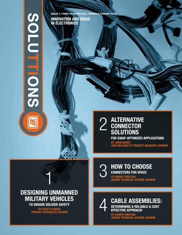
SOLUTTIONS
ISSUE 5, THIRD QUARTER 2021, WIRING & CONNECTORS
INNOVATION AND IDEAS IN ELECTRONICS
2
ALTERNATIVE CONNECTOR SOLUTIONS FOR SWAP-OPTIMIZED APPLICATIONS BY JOHN BRUNT, HIGH RELIABILITY PRODUCT MANAGER, HARWIN
1 DESIGNING UNMANNED MILITARY VEHICLES TO ENSURE SOLDIER SAFETY BY SCOTT FLOWER, PRODUCT SPECIALIST, HARWIN
3
HOW TO CHOOSE
4
CABLE ASSEMBLIES:
CONNECTORS FOR SPACE BY WENDY PRESTON, SENIOR TECHNICAL AUTHOR, HARWIN
DETERMINING A RELIABLE & COST EFFECTIVE APPROACH BY WENDY PRESTON, SENIOR TECHNICAL AUTHOR, HARWIN
Streaming a Car Chase 32,000 feet over Nebraska
Harwin Datamate Series Makes the Connection Datamate, the industry standard in high-dependability connectivity solutions, delivers 2.0mm pitch high-reliability connectors offering high electrical performance, sustained mechanical durability and ultimate design flexibility, to let your projects to soar.
Avionic and engine controls, guidance systems, power control systems and radar and tracking demand the highest-quality components that optimize your size, weight and power (SWaP) requirements – when facing extremes of shock, vibration and temperature. In Stock Now – Contact Your Local TTI Specialist
Learn More
1.800.CALL.TTI or tti.com ISSUE 5 | THIRD QUARTER 2021 | WIRING & CONNECTORS 2
WELCOME TO SOLUTTIONS ISSUE 5, THIRD QUARTER 2021, WIRING & CONNECTORS
CONTENT 1 2 3 4
DESIGNING UNMANNED MILITARY VEHICLES TO ENSURE SOLDIER SAFETY BY SCOTT FLOWER, PRODUCT SPECIALIST, HARWIN
ALTERNATIVE CONNECTOR SOLUTIONS FOR SWAP-OPTIMIZED APPLICATIONS BY JOHN BRUNT, HIGH RELIABILITY PRODUCT MANAGER, HARWIN
HOW TO CHOOSE CONNECTORS FOR SPACE BY WENDY PRESTON, SENIOR TECHNICAL AUTHOR, HARWIN
CABLE ASSEMBLIES: DETERMINING A RELIABLE & COST EFFECTIVE APPROACH BY WENDY PRESTON, SENIOR TECHNICAL AUTHOR, HARWIN
SoluTTIons is a regular publication of TTI, designed to bring clear, current information about the rapidly changing world of electronic design to engineers in the electronics industry. Sourced from industry insiders and thought leaders, these case studies, white papers and marketing intelligence overviews are selected to be informative and thought provoking.
DESIGNING UNMANNED MILITARY VEHICLES
1
Keeping military personnel out of danger is challenging for today’s defense forces. Many of the threats they face are ad-hoc, improvised and unpredictable. The utilization of unmanned vehicles on land, sea or air can help to mitigate such threats, reaching places that would be impossible or unsafe for conventional vehicles.
To Ensure Soldier Safety
By Scott Flower, Product Specialist, Harwin
ISSUE 5 | THIRD QUARTER 2021 | WIRING & CONNECTORS 4
Unmanned Vehicles Unmanned Aerial Vehicles (UAVs)
Unmanned Ground Vehicles (UGVs)
Unmanned Underwater Vehicles (UUVs)
UNMANNED VEHICLE CAPABILITIES Unmanned aerial vehicles (UAVs) have been serving purposes such as surveillance and reconnaissance for a considerable period and can deliver ‘eye in the sky’ capabilities to ground troops in real-time. Larger platforms have been in common use by many defense forces, delivering missile capabilities into zones not safe for piloted deployment. With the added video and thermal imaging equipment, targeting and confirmation can be carried out by the command structure at bases some distance from the target. Unmanned ground vehicles (UGVs) are now smart enough to carry supplies to frontline forces, and can also be used for tasks like rescuing injured soldiers from dangerous positions during battle; something which requires a level of dexterity and control beyond the scope of earlier autonomous machines.
As levels of on-board intelligence continue to rise, military planners can conceive an increasing diversity of vehicles to carry out more complex missions. Low-cost commercial drones like quadcopters could also be used by militias or terrorist groups to launch improvised attacks or gather information. Drones have been used to deliver grenades in the conflict in Syria, and there is the prospect that large numbers of drones operated as swarms could be employed to implement highly effective assaults on even the most well defended of targets. While government agencies work out how to counter these emerging threats, they are themselves investigating opportunities for swarming large numbers of small, expendable drones to carry out unmanned strikes. We could be looking at a new facet of the arms race developing.
Unmanned underwater vehicles (UUVs) can carry out surveys of undersea terrain and defenses, giving up-to-date information on navigational routes. With additional sensors, threat detection is added to the vehicle, or information on tidal flow or other sub-sea currents to determine movement of other underwater objects.
ISSUE 5 | THIRD QUARTER 2021 | WIRING & CONNECTORS 5
ADVANCED TECHNOLOGIES Having the best unmanned vehicles will be critical for keeping the upper hand, and this will be heavily dependent on advanced electronics and computing technologies specified. Typically, propulsion for these unmanned systems are electrically based – requiring efficient, high-speed motor drives. Often, the vehicles are loaded with a rich set of sensors (carrying any combination of motion sensors, optronic sensors, proximity sensors, thermal sensors, radar, GPS and high-definition cameras) for functions such as navigation, threat detection, obstacle avoidance and intelligence gathering. Vehicles for tasks like recovery will also have mechanisms like grippers and multiaxis motion controls. This means they will have complex electrical subsystems, encompassing battery management, power electronics, signal processing, sensor fusion, computing and communication elements.
With the advancement of artificial intelligence (AI) on these vehicles, enabling autonomous operation for extended periods of time, the ‘brain’ of the vehicle must necessarily become more complex. More electronics, more wiring, and more connections are required. The electronic circuitry may be more sensitive to electromagnetic interference (EMI) or radiofrequency interference (RFI), which could compromise the operation and activities of the vehicle. All these onboard computers, electronic devices, batteries and electrical drive systems add up to a significant number of PCBs, components and wiring. Even a small vehicle will require extensive electrical infrastructure to deliver data and power to the places they are needed. At the same time, careful attention to wiring and system design is called for in order to avoid excessive weight, prevent detection and minimize vulnerability to attacks that could range from hand-gunfire to electronic warfare. Trimming weight from on-board systems is always very important, so as to maximize agility and range, as well as allowing for a greater payload or more functionality to be integrated.
Consolidating and centralizing the wiring can streamline cable armoring to save weight. It can also help optimize weight distribution, which can be extremely important in a UAV. Concentrating the wiring within a wellprotected area can, in addition, minimize the probability that attackers firing small arms or nearby explosive concussions could disable the vehicle. During the sub-system manufacture and vehicle assembly stages, as well as ongoing maintenance and upgrade, processes can be much easier and faster with less cabling to manage. With both reductions in manufacturing time and materials used, costs are reduced – potentially releasing budget for use on other elements within the vehicle.
ISSUE 5 | THIRD QUARTER 2021 | WIRING & CONNECTORS 6
DEVELOPING CONNECTION DESIGNS Addressing the needs of the military/ aerospace sector, Harwin’s wiring design and manufacturing service can quickly manufacture prototype cable assemblies and produce economical small-batch production using specialist tooling. Cabling is carried out by operators trained to IPC-620 wiring standards, who are very familiar with the requirements of the connectors. Completed cable looms are 100% inspected and tested. Our high-reliability connectors support the trend towards centralization by offering designers many options to miniaturize, ruggedize and reduce the weight of the vehicle’s wiring. Connectors in the popular Datamate family allow power, signal and RF contacts to be integrated into the same housing, with current ratings up to 40A per contact being supported by Datamate MixTek products. The numbers of power, signal and RF connections is also configurable to meet the specific needs of individual projects. Harwin’s engineering team has also designed high strength and retention force into connectors with even smaller contact pitch and housing dimensions. Our Gecko series presents a high-performing, modern alternative to traditional micro-D connectors. These components have a pitch of 1.25mm and maintain continuity throughout a wide range of operating conditions. The screwlockable Gecko-SL series demonstrates outstanding performance in vicious bump and vibration tests. With the addition of Gecko-MT to the range, Harwin brings the smallest, lightest mixed-technology connector to the market, combining signal and power for great flexibility in a tiny size. For maximum power requirements, Kona brings 60A per contact in a high-reliability connection. These larger 8.5mm pitch interconnects perform to the same high levels of vibration, shock and temperature as the rest of Harwin’s hi-rel connectors. The individually shrouded contact design gives a maximum voltage of 3000V, suitable for autonomous vehicle power systems.
ISSUE 5 | THIRD QUARTER 2021 | WIRING & CONNECTORS 7
PROTECTING VULNERABLE ELECTRONICS As more unmanned vehicles enter service in a growing variety of roles, they will have to deal with countermeasures of numerous forms - such as electronic jamming and cyber-attacks. Onboard the vehicles themselves, and throughout the supporting infrastructure, proper shielding of connectors and cables will lay the foundation for connections that are resistant to interference and free of presence-signifying electro-magnetic interference (EMI) leaks or opportunities for electronic eavesdropping. Harwin offers a variety of solutions that are optimized for such purposes. For Board-Level Shielding (BLS), SMT clips hold simple RFI shield can to the board. The removable and replaceable cans eliminate the need for hand soldering these cans to the PCB, and components under the can are easily accessed if required for maintenance. For cabling, both Datamate and Gecko ranges include metal backshell accessories, for shielding cable assemblies and any mating board-mounted connections. 100 years after the initial stages of mechanized warfare, the increasingly intelligent unmanned vehicles now being seen could revolutionize military combat – just as technical innovations, like tanks and aircrafts, changed the face of fighting more than a century ago.
ISSUE 5 | THIRD QUARTER 2021 | WIRING & CONNECTORS 8
Running 118 Spot Welds Every 45 Seconds
Harwin Kona Series Makes the Connection Capable of achieving up to 60A and 3000V per contact and designed for intense vibration and shock resilience, these low-profile, high-power Kona connectors are opening up a whole new world of possibilities in robotics.
Robotics are becoming an everyday occurrence from space, to the factory floor. Harwin’s powerful new Kona 8.5mm pitch Connectors are breaking new ground in high-dependability and high-performance for size, weight and power (SWaP) efficiency. In Stock Now – Contact Your Local TTI Specialist
Learn More
1.800.CALL.TTI or tti.com ISSUE 5 | THIRD QUARTER 2021 | WIRING & CONNECTORS 9
ALTERNATIVE CONNECTOR SOLUTIONS
For SWaP-Optimized Applications By John Brunt, High Reliability Product Manager, Harwin
2
The D-type connector format has been around for several decades having first appeared in the 1960s. These components provided engineers with interconnect solutions that were relatively compact and had good overall mechanical robustness. Because of these characteristics, they saw deployment in a wide range of high-reliability (HiRel) applications where there are space limitations, including in military and aerospace systems. Though these connectors proved themselves to be very suitable in such applications for many years, the engineering requirements set by later generations of electronic design called for further miniaturization. Micro-D, a derivative of the D-type connector, was introduced to address this trend. Additional applications in robotics, medical equipment and satellite hardware have all benefited from the adoption of Micro-D. With the density of electronic systems continuing to increase, the inadequacies of Micro-D have become more apparent. Today, engineers are looking at new lightweight connector technologies capable of supporting a greater number of contacts, while taking up only minimal space. The following article will describe the highly optimized solution that Harwin has developed, and show how it has several key attributes that set it apart from Micro-D.
ISSUE 5 | THIRD QUARTER 2021 | WIRING & CONNECTORS 10
13.97 23.75
4.90
7.87
10.90
21.45
7.60
12.05
Figure 1: Footprint comparison of Gecko-SL and Micro-D connectors
AVOIDING THE SHORTFALLS OF MICRO-D Like the D-type connector, Micro-D’s contacts are arranged in staggered rows. This means only odd contact numbers can usually be supported – which can require selection of a larger connector. There are also limitations on the number of contacts each unit can practically accommodate. The 1.25mm-pitch Gecko connectors supplied by Harwin present engineers with ultra-compact interconnect solutions that can fit in far more contacts than Micro-D. They offer a 45% reduction in the overall size compared to their Micro-D equivalents. This is illustrated in Figure 1, where the footprint of a 16-pole Gecko-SL connector (in dark orange) has been overlaid onto an equivalent 15-way Micro-D connector (in light orange). In addition to the size reduction, their glass-filled thermoplastic housings make them much more lightweight – weighing
much less than the corresponding Micro-D, while still having the necessary insulation characteristics. Use of a Gecko unit can result in the overall weight of the connector being as much as halved – with a 10-contact Gecko weighing just 0.9g compared to 1.7g for a 9-contact Micro-D, and a 50-contact Gecko weighing only 2.1g while a 49-contact Micro-D would weigh 4.7g. These housings are able to cope with exposure to extreme temperature levels, with an operational temperature range spanning from -65°C to +150°C. They also exhibit industry-leading outgassing properties when placed in a vacuum, something which is of particular value in space deployments. Gecko connectors, just like Micro-D connectors, can be used in a wide variety of different application scenarios, with boardto-board, wire-to-board and wire-to-wire configurations all supported. But, unlike Micro-D, Gecko is available with numerous housing arrangements and mounting styles covered. In contrast to the staggered contact layout of Micro-D connectors, the dual-row Gecko components (with their rectangular housings) are better able to address situations where there are even contact number requirements. This means that
larger connectors, with superfluous contacts, will not need to be specified – keeping the bill-of-materials costs and space used to a minimum. The screw-machined beryllium copper contacts incorporated into these connectors allows them to deliver comparable electrical performance, with each contact being rated to simultaneously carry currents of up to 2A. The contacts are gold-plated to minimize resistance and ensure long-term durability. Thanks to its patented 4-finger design, at least one surface of each of these contacts and their respective plugs are touching under heavy shocks or intense vibrational forces, ensuring that an electrical connection is always maintained. The Gecko series has been thoroughly tested with vibrations of 1.52mm amplitude applied, cycling between frequencies of 10Hz and 2000Hz for a period of 6 hours. 100G shocks are likewise applied in the Z axis for 6ms, and 50G in the X and Y axes for 11ms.
ISSUE 5 | THIRD QUARTER 2021 | WIRING & CONNECTORS 11
The robust construction of Gecko connectors enables them to support over 1000 mating cycles. This is double what could be expected for a Micro-D connector. Depending on the level of interconnect retention needed and space available, these components can be offered with screw-lok or latched options. The strong stainless steel screw fixings used here provide a high degree of strain relief. An example of this screw-lok mechanism is shown in Figure 2. To get an understanding of the greatest power density improvements that can be realized by migrating from Micro-D to Gecko, let’s now look at an example. Figure 3 shows the footprint of a 26-pole Gecko latched connector (in dark orange). This can deliver a total current of 52A via its contacts, across a 0.740-inch (18.80mm) length, equating to a power density of nearly 70.3A/inch. That compares very favorably to the Micro D (shown in light orange). Here 75A can be delivered across its 25 contacts (each being rated at 3A), but the length
involved is 1.185-inches (30.10mm) which equates to a 63.3A /inch power density. Using Gecko latch-based connectors allows 11% additional power to be delivered for a given length of connector. Through the introduction of new Gecko-MT connectors, even greater power densities can be achieved. Here, the data contacts are accompanied by dedicated power contacts, which each have an impressive 10A current rating. It should also be noted that Gecko connectors are not only shorter than the Micro-D, but also substantially slimmer shown in Figure 4. This results in still greater space savings for any given power rating. The availability of horizontallyoriented versions of Gecko-SL and GeckoMT is another plus point. This means that connectors/cabling can be positioned at the outer edges of a PCB, so that such boards can be stacked closer together and any available space is better utilized.
Figure 2: A Harwin Gecko-SL connector with mate-before-lok screw-lok fixings
CONCLUSION Though the Micro-D connector has been a very effective way to implement compact and reliable interconnects for many years, the demands now being placed on electronic systems mean that, in many cases, it is now becoming an outdated approach. The combination of comparable performance, alongside reduced size and improved power density enables Harwin’s Gecko series to bring clear advantages. These low-profile connectors offer space and weight savings, and the increased contact versatility translates into cost reductions too, while still meeting the most exacting performance expectations.
Figure 4: Gecko connector vs Micro-D size
Figure 3: Gecko Latch and Micro-D connector power density comparison
30.10
7.87
5.00
18.80
ISSUE 5 | THIRD QUARTER 2021 | WIRING & CONNECTORS 12
Plugging into a Power Source 93 Million Miles Away
Harwin Gecko Series Makes the Connection Harwin’s robust yet miniature Gecko 1.25 mm pitch connectors, offer a compact design up to 45 percent smaller and 75 percent lighter than Micro-D alternatives. Gecko provides superior dependability and high-performance for size, weight and power (SWaP) efficiency.
In critical space applications at extreme operational conditions, like satellites and CubeSats, radar communication and launch systems, Gecko High-Reliability Connectors deliver exceptional performance in a small package and can make the difference between mission success and failure. In Stock Now – Contact Your Local TTI Specialist
Learn More
1.800.CALL.TTI or tti.com ISSUE 5 | THIRD QUARTER 2021 | WIRING & CONNECTORS 13
HOW TO CHOOSE
3
There are many demanding applications on Earth, and many high-reliability connectors exist that will do a fine job performing in those environments. But space brings a few additional tricky problems, and a little extra planning is needed to make sure these are factored into the connector choice.
Connectors for Space
By Wendy Preston, Senior Technical Author, Harwin
ISSUE 5 | THIRD QUARTER 2021 | WIRING & CONNECTORS 14
CONSIDERATIONS Before we look at each of these issues in detail, we first need to define a key phrase in that first sentence. If you work in the space industry, your definition of “high-reliability” may be slightly different from how we use it in the connector industry. Often, the space version of high-reliability means missioncritical and involving risk to human life. Devices that are not quite so critical will be labelled “commercial”. For the connector industry, any application that subjects the connector to vibration or temperature variations requires a “high-reliability” connector.
Vacuum
Cosmic and Thermal Radiation
CAN I JUST SPECIFY SPACE-APPROVED CONNECTORS? You could specify space-approved connectors everywhere on your build – but this comes with a technology and cost penalty. Typically, space qualification of an electronic device is an incredibly lengthy process and can take several years to achieve. This has resulted in a list of qualified components that are old technology – it’s just not possible for the long process to keep up with the pace of development. It’s also an expensive qualification process, and this will be reflected in the final price of the products. Specifying from the approved list will mean older, heavier, larger and more expensive components are your only choices. Companies in the CubeSat industry (as an example) are free to innovate and pursue the best & latest technologies available, not restricted by the requirements of space approval. Let’s consider each of the challenges listed earlier, and some aspects to consider in your connector choices.
VACUUM OR PARTIAL VACUUM The lack of air affects the maximum voltage rating of a connector – the moment of flashover from a conductor to the nearest metal item. Flashover will occur at a different voltage depending on the density of the air molecules, so look out for connectors that have a voltage rating for altitude. Then there is outgassing, or off-gassing. This is not specific to electronics – it’s an effect that occurs in all materials, and is the release of gas dissolved, trapped, frozen or absorbed. Causes can be sublimation and evaporation (phase transitions of a substance into a gas), desorption, seepage from cracks or internal gaps, and gaseous products of slow chemical reactions. This introduces contaminants into the equipment, which might cause problems at any time during the life of the product. Both NASA and ESA (the European Space Agency) specify recommended volume levels of outgassing for materials used in their space applications, so check with the manufacturer if their materials meet these levels.
Cost of Pushing Mass Away from the Earth’s Gravity
COSMIC AND THERMAL RADIATION Space (Volume) Allowance in a Rocket
Vibration at Launch
Cost of Failure and Repair
Cosmic radiation is a problem as you increase altitude and our protective atmosphere thins. The levels are detectable even in normal air travel, so in partial vacuum it is a significant issue. The effects are like EMI in ground-level electronics – and the solution is the same: shielding. The metal case of the space vehicle will provide some protection but added shielding on vulnerable PCBs or cables should also be considered. Thermal radiation increases when your space vehicle is in direct sunlight with no atmosphere – but the temperature can also drop to very low levels in shadow, or even on the side of the vehicle away from the sun. If your satellite has its own rotation, there will be constant thermal cycling of the outermost layers. This is less of an issue if the electronics are buried deep into the center of the vehicle, as the direct thermal effects are much lower. But with a CubeSat measuring just 10cm across, thermal cycling of all components is a concern. Check the connector specifications for max and min temperature range during operation (not just soldering heat resistance). Look for additional testing for thermal soak (sometimes listed as high temperature, long term or temperature life) and thermal cycling.
ISSUE 5 | THIRD QUARTER 2021 | WIRING & CONNECTORS 15
THE COST OF WEIGHT, THE COST OF VOLUME Every gram pushed into space from the Earth’s surface costs money. More mass equals a bigger vehicle. The bigger your vehicle, the more room you have; however, the more fuel you need to be able to carry. Both volume and weight carry penalties – and rockets & rocket fuel are not cheap. So, you need small and light. Every gram saved on a connector is a gram that can be spent on the payload. Look for connectors in the performance bracket you need that are also the smallest and lightest possible. Don’t over-specify where you don’t need to. This is especially true in the CubeSat market. These are miniature satellites designed to be multistacked in a rocket, and both space and weight are at a high premium. But longevity and human life are not factors, so the cost of failure is much lower than a manned vehicle.
STRESS AT LIFT-OFF Launch is a high vibration, high acceleration environment. Your connections need to be able to survive this period intact and still mated, so they can be ready to perform once floating in orbit. Make sure your connectors are rated for vibration, shock and acceleration. Specify jackscrews or latching where possible.
COST OF FAILURE AND REPAIR Are you transporting astronauts and cosmonauts, space telescopes or the next Mars rover? As disappointing as a failure of your CubeSat might be, it’s not going to cause loss of human life or a million-dollar setback (probably). Avoid over-specification and choose your budget wisely. Set your connector requirements based solely on your performance requirements, not paranoid “what-if” scenarios.
HOW CAN HARWIN HELP? We can help get the best from your design and budget by choosing connectors that meet your specifications. Our high-reliability connectors are as small and light as we can make them, whilst still delivering amazing current (power) levels for their size. Every feature on the product has a purpose, and the final design is cost-effective compared to industry standard alternatives. Gecko-SL has been a firm favorite for the growing CubeSat industry since its launch. The compact size and very light weight are minimal for the performance achieved. The average weight of each connector is just 1 gram, including robust screw-loks to overcome any vibration issues. The plastic used meets NASA and ESA expectations. CubeSats comprise of a dense stack of PCBs, so height above each PCB is limited. Gecko-SL now offers both horizontal connectors and mating cable assemblies to solve this challenge. By installing the horizontal connectors on the edge of the PCB, you can route the cables sideways round the stack edge, saving space above the PCB. The cables are ready-made and in stock, further reducing the upfront cost of your project.
See how we can help you with connectors and hardware for your space application.
ISSUE 5 | THIRD QUARTER 2021 | WIRING & CONNECTORS 16
Real Time Intelligence from 300 Meters Above the Field
Harwin M300 Series Makes the Connection SWaP optimized Harwin M300 3.0mm pitch connectors save PCB space and weight while maximizing power in the most extreme environments when failure isn’t an option.
Whether it’s a small camera drone or a menacing unmanned combat vehicle, the consequences for failure in military applications are extremely costly in an arena where size, weight and power (SWaP) optimization is essential. In Stock Now – Contact Your Local TTI Specialist
Learn More
1.800.CALL.TTI or tti.com ISSUE 5 | THIRD QUARTER 2021 | WIRING & CONNECTORS 17
CABLE ASSEMBLIES:
Determining a Reliable & Cost Effective Approach
By Wendy Preston, Senior Technical Author, Harwin
4
Cable assemblies fulfill an important role in today’s high-density electronic systems, facilitating connectivity between different parts of the system. Sometimes thought of as being ‘just a couple of connectors and some cable’, these are in fact an essential element of modern engineering design and should not be underestimated, but instead given the consideration that they deserve. In this technical white paper, we will outline the process of creating cable assemblies for application sectors requiring the highest levels of reliability, such as aerospace and motorsport. Details will be given of the considerations that need to be factored in when creating a robust cable assembly to support a long operational lifespan, with areas being highlighted that can have an influence on reliability.
ISSUE 5 | THIRD QUARTER 2021 | WIRING & CONNECTORS 18
DEFINING YOUR ASSEMBLY INTRODUCTORY ASPECTS A cable assembly is a form of electronic sub-system and can have bearing on the overall performance of the system into which it is incorporated, depending upon the design followed. Therefore, it is important to spend time, at the earliest possible stage, to think through the arrangement of the cable assembly and how it may affect the system. Cable assemblies can have a variety of names; wiring assembly, cable loom or wiring loom, cable harness or wiring harness. These interconnection systems all involve connectors designed for cable attachment, connected by one or more wires. Cable bundles can be bound together for cable management, protection and ease of installation. SELECTION AND DESIGN In some cases, the connectors are defined by what is already on the PCBs, and the cable assembly needs to provide a connection between boards (or to a test fixture). In other cases, if the PCB designs are not finalized, there may be an opportunity to change connectors to a type that not only suits the PCB/system, but is also simple and effective in relation to the cable assembly. This could include selecting a connector type that you have prior experience using, and considering readily available tooling. Tooling is one of the most expensive parts of building high quality and reliable cable assemblies, and can have a significant impact on the cost of a project. This is especially true for low volume cable assemblies, such as prototypes and test rig cables. With higher volume projects, the investment in tooling can Figure 1: Solid core or stranded Solid
be amortized and, consequently, have a relatively small impact on the cost of each cable assembly produced. Key elements that can potentially impact the ease of use of any cable assembly include polarization features, jackscrews or latching, and backshells or hoods should all be considered at this early stage. While the connectors are often predefined, selecting an appropriate cable is not as simple – there are many more options and more criteria to consider. The main elements that will drive this decision are the type of signals (or power) to be carried, the application/ environment, and the cable routing. Certain specialist applications (such as RF, data communications or products like thermocouples) have standards that define the cable. This, in many ways, means that the decision-making process is easier. However, for more general applications, the following sections highlight some of the criteria to be contemplated. Cable Type The cable type is often defined by the application as well as the connector style. This could be co-axial for RF applications, ribbon cable for insulationdisplacement contact (IDC) connectors, shielded for sensitive applications, or just simple equipment wires for general purpose applications. If some or all of the cable is to transmit power, these conductors must be sized appropriately, not only to ensure that they can handle the current but also to ensure that the voltage drop along the cable length is acceptable in all operating conditions. The conductor count is often intuitive, but techniques such as using multiple cores to transmit power may have an impact. • Solid Core or Stranded If the application is outdoor or involves exposure to harsh environmental conditions, or if cost is likely to be a Figure 2: Shielding Insulation
significant factor, then solid core can be a good option, as it is resistant to damage and generally easier to implement (hence, making it cheaper). However, these cables can also be harder to crimp, and are more inflexible and resistant to reshaping than an equivalent stranded version. In the smaller applications of electronics (as opposed to electrical deployment), multistrand is preferred. (Figure 1) • Shielding Cable assembly shielding needs to be considered in a two-way environment. In some applications, the shielding may be required to protect high-impedance signals in the cable from interference as they pass noisy areas of the system. Conversely, if the cable assembly is carrying high-speed digital signals, then shielding can protect sensitive areas of the system that the cable passes through. Taking this one step further, the shield may cover all conductors as a group or as pairs or individually. This can be important if the cable is to carry both analog and digital signals, as it will shield one core from another – thereby preventing crosstalk. (Figure 2) • Insulation The routing of the cable assembly is a key criteria for selecting insulation. Is the outer sheath of the cable likely to be exposed to extreme temperatures, chemicals or physical damage, such as abrasion? Any damage or degradation that exposes conductors can impair function and create a serious safety hazard. The insulation on individual cores also needs to be considered, especially with regard to the dielectric strength that prevents any electrical breakdown. Insulation is also a key factor in determining the minimum bend radius for the cable, which is an important parameter for routing, especially in restricted locations. (Figure 3)
Figure 3: Insulation Outside Insulation Cable Bend Radius
Copper Wire Stranded
Copper Mesh
ISSUE 5 | THIRD QUARTER 2021 | WIRING & CONNECTORS 19
• Strain Relief The application and environment will also have an effect on some of the finishing operations that could form part of the design. For example, some shell-type connectors include an inset that can be filled with an epoxy resin after assembly. This process, known as ‘backpotting,’ provides a degree of strain relief on the cable assembly and also mitigates the ingress of dust which can be a source of premature failure. See, "Addressing the Practical Issues of Cable Assembly" in this white paper for further information on the backpotting process. With other connector types where no backpotting void is present, the simple application of heatshrink can group individual cables and provide strain relief. Heatshrink can also be applied over the outer sheathing of cables to provide increased rigidity and protection against wear mechanisms, such as abrasion. Another strain relief method is to add backshells to the connector assembly. While only possible with connector systems that have a provision for this, backshells are available in plastic and metal versions that provide significant mechanical strength as well as somewhere to grip the connector when mating/un-mating. Metal versions often used with shielded cables offer a means of termination for the braiding/shielding, ensuring that the connector itself is also shielded. (Figure 4) Routing When considering the cable run, there may be a need for ‘forming’ the cable so that it avoids sensitive parts of the system, or simply makes use of available space for routing the cable assembly. In systems with movement or vibration, the cable assembly has to be routed close to the chassis so that it can be attached and supported. Cable management products can assist with securing looms to chassis or PCBs, and (depending on vibration) further anti-wear measures could be required at these points.
Cable clip design should be considered as part of the complete harness installation. Twisted Pairs This is a method of twisting two or more cables within the cable bundle, most typically in pairs. It has the effect of reducing electromagnetic radiation and crosstalk between neighboring pairs of lines. The twist will have a specific pitch, usually defined in TPI, or twists per inch. Lacing and Cable Ties Cable ties are the most common and cheapest form of cable management, and taking this approach is perfectly sensible when the space allows, and wear due to vibration is a factor. Cable lacing is an older type of cable management for binding cable bundles. The lacing forms a single cable assembly without any obstructions along the length, unlike plastic or hook & loop cable ties, making it still a valid choice in tight spaces. Identification The final consideration at the design stage is whether any cable marking/identification is required. This can be in context of the overall assembly (so that spares can be ordered) or for individual wires to identify routing of important signals. If the cable assembly is intended to be a service item in the field, assembly marking should be deemed essential to assist service technicians. Once all these aspects have been considered, the outcome should be a drawing package for the final cable assembly that includes a schematic, a mechanical outline and a complete billof-materials (BOM) that lists all of the components (including wire, connectors and accessories). As a result of creating this drawing package, the designer should also have a good idea of the manufacturing processes and tooling/jigs that will be required, whether this is for low-volume prototyping or a full-scale production run.
Figure 4: Strain relief
Heatshrink Application
ISSUE 5 | THIRD QUARTER 2021 | WIRING & CONNECTORS 20
SOLDERING
ADDRESSING THE PRACTICAL ISSUES OF CABLE ASSEMBLY MANUFACTURING PROCESS Although the design will naturally determine the theoretical reliability of the cable assembly, it is on the manufacturing floor where the reliability battle can be won or lost. While the attachment of connectors may seem simple, there are many aspects that need to be executed well, each and every time, to ensure a reliable end product. The two principal methods of making connections to an individual terminal are crimping or soldering, each of which is a completely different process. In addition, multi-contact connection is possible with IDC. CRIMPING With crimping, the wire is stripped and inserted into a metal terminal. The terminal is then squeezed and deformed around the wire strands to ensure a good mechanical and electrical connection. There are two main styles of crimp, and although the crimping process is quite similar, the visual result is very different and the tooling must be correctly matched to the crimp type. Open Crimps There are a number of names of crimps that fall into this category - B, D or F crimp, open-barrel, O crimp or overlap crimp. They are typically recognizable due to the flat material used to make the complete contact, which will be bent into a U-shape where the wire will be attached. The exposed conductor and the end of the insulation is placed into the U-channel, and the tooling will then bend the two arms of the U over or into the wire conductor (depending on the product) and over the insulator (for additional strain relief). (Figure 5) Barrel Crimps Named because the crimp section of the contact resembles a barrel (or tube), here the wire is inserted into the bore inside the crimp, and the tooling will deform a number of indents evenly spaced around the barrel. (Figure 6)
Figure 5: Open crimp example
With soldering, the wire is again stripped and inserted into the terminal. The joint is then heated, and solder is subsequently introduced to make a good mechanical and electrical connection. No tooling is required, but the process is generally manual. (Figure 7) IDC These types of contacts are generally preassembled into the connector body, and wire is inserted in all contacts in one process. The wire used will normally be ribbon cable (although individual IDC connections do exist). This wire is not stripped – the IDC end of the contact has sharp cutting edges, which pierce through the insulation when the cable is pressed down onto the contact. These edges penetrate to the conductor in the middle, and make a good compression joint for electrical connection. The whole ribbon cable is clamped in place for mechanical strength.
Figure 6: Barrel crimp example
Figure 7: Solder contact example
It is very unusual for connectors to be available in more than one connection type, so the cable connection method will have been determined at the design phase when the connector and terminals were chosen. (Figure 8) Figure 8: IDC connector, with cross-sectional views
Deformation Contact Surface
After Displacement
ISSUE 5 | THIRD QUARTER 2021 | WIRING & CONNECTORS 21
KEY PROCESS ISSUES It is easy to cause reliability issues even with the simplest processes involved in cable assemblies. Wire Stripping If the blades of the stripper are not set correctly then the insulation may be torn, or the wire strands could be scratched or cut. If the blades are misaligned, then the insulation may be cut at an angle. These can cause failure modes; the wire may not sit in the terminal correctly, so it may not crimp as expected or be held securely, and weak points on the conductor from scratches or cuts can lead to the wire separating from the connector while in use. Different wire types, such as power and signal, can require different stripping tools and will certainly need different tool settings to be applied; meaning that at least one tool per wire type/size will be mandated for efficient production. Simple jigs and hand tools can be used for low volume production/ prototyping, but stripping machines are recommended for mid-to-high volume operations. This will also aid repeatability – ensuring that the correct length of insulation and total cable length is stripped consistently each and every time. More complex cables, such as coaxial, are harder to strip by hand, and can only be stripped accurately and with consistent repeatability by automated processes. (Figure 9) Crimping Similar issues exist at the crimping stage. Tooling will again be specific to each crimp type and wire size, and additional tooling needs to be considered every time a new crimp is introduced. Hand tools are generally available, but for higher volumes, automated or semi-automated tooling is recommended. Full automation machinery exists to complete the whole strip and crimp process within one workstation. Better repeatability can be assured with the more automated processes.
Consistency and Repeatability Repetition is one of the key factors in ensuring that good quality is maintained, and thus producing reliable cable assemblies. In order to provide consistency, most cable assembly companies have adopted the IPC-A-620 standard. This standard is a collection of visual quality acceptability requirements for cable, wire and harness assemblies and describes acceptability criteria for producing crimped, mechanically secured or soldered interconnections. It also covers associated lacing/restraining criteria for cable and harness assemblies. It is important that manufacturing staff are adequately trained so that they are able to meet the requirements of IPC-A-620, and that their training is maintained and continuously updated (in addition to any specific training required in relation to the connectors involved). This, in itself, can be a significant hidden cost to companies, especially those that are just starting out in cable assembly. While consideration of these process issues will help uncover quality-related problems, they are also very useful to identify longerterm dynamics, such as tool wear. Over time, tooling (and even jigs) will wear and require either replacement or adjustment to safeguard against any drop in quality levels. The associated downtime or tooling replacement represent further operational expense, which will need to be factored into the overall cost of the cable assembly. FINISHING STAGES Once the cable assembly is assembled and has passed the initial stages in-process inspection and testing, then the finishing processes can begin. Again, the processes involved here will have been defined at the design stage and can include things such as backpotting, overmolding, lacing and labelling to name just a few.
Backpotting This process is a method of sealing the rear of a connector with an epoxy resin or similar compound. It gives the advantages of additional strain relief without too much additional connector weight. The strain relief afforded will resist both removal by direct pulling on wires, and with side-loading of wires. Strength is therefore improved and this increases the reliability of the whole connector – when processed correctly. A step-by-step guide to the backpotting process is available online at https://www.tti.com/content/ttiinc/en/ manufacturers/harwin/resources/a-stepby-step-guide-to-backpotting.html. At this stage, compliance with IPC-A-620 remains crucial, as each of the finishing processes can still have an impact on the reliability of the final assembly. Some processes will require the development and use of fairly elaborate jigs to ensure that the final cable assembly meets the required mechanical specification. Each jig will be unique to a specific cable assembly so this again can represent a significant expense if multiple types of cable assembly are to be produced. The last step will be the final inspection and test. This will vary significantly, depending upon the type of cable assembly and the technologies involved (e.g. power or RF). However, it will almost certainly involve a visual inspection, plus mechanical testing and some electrical testing. Any failures at this point are likely to result in scrapping, thereby adding significantly to the overall cost through lower yield rates. THE BIG QUESTION – MAKE OR BUY? The Cost of Production Many companies still make cable assemblies in-house, especially for prototypes and low volume production runs, believing that to outsource would be an expensive proposition. However, with the reliability of the cable assembly being influenced by
Figure 9: Examples of poor stripping
ISSUE 5 | THIRD QUARTER 2021 | WIRING & CONNECTORS 22
so many different dynamics – including design, workmanship, production process, staff knowledge/experience and a wellformed production environment with appropriate tools, jigs and fixtures – building a reliable cable assembly in-house can prove to be a very expensive proposition. The Cost of Failure As systems rely on high quality interconnection, a sub-standard cable assembly will almost certainly lead to full or partial system failure sooner or later, especially in rugged applications. Replacement costs can be high and the damage to reputation can be even higher. Prototypes might fail testing due to a bad cable assembly, thus leading to longer development periods and also higher testing costs while the nature of the fault is traced. For simple cable assemblies, with low volumes involved and experienced engineers available, in-house cable assembly is an easy decision and probably quite low risk. If any or multiple factors change, the costs – whether that is additional tooling/equipment investment, jigs/ fixtures, new and ongoing staff training, maintenance of production equipment, inspection and test – can
escalate rapidly. A point can soon be reached where it is an unjustifiable expenditure. At this point, a specialist cable assembly house becomes a much better proposition for future requirements. In situations where no cable experience exists in-house, the decision to outsource this activity should be a much more straightforward decision. A make or buy decision tree is available online at https://www.tti. com/content/ttiinc/en/manufacturers/ harwin/resources/make-or-buy-cableassemblies-decision-tree.html. OUTSOURCING TO EXPERIENCE Experienced and dedicated cable assembly facilities, such at those available at Harwin, provide a viable and practical alternative to in-house manufacturing. Costs are reduced as the manufacturing staff are all IPC-A-620 trained and then re-trained on an ongoing basis as part of the operating costs of the sub-contractor themselves. Tools are often already in place and regularly maintained, and many simple jigs are directly available, with the knowledge and experience to rapidly build more complex jigs as required.
THE EXPERTISE AT HARWIN With a flexible production approach, such as that in place at Harwin, it becomes economically viable to build extremely low volumes, even a single cable assembly. Indeed, while the company can handle production builds in the thousands, its minimum order quantity (MOQ) remains very low for all cable assembly types, often less than 10 units. This allows customers to purchase production-standard cable assemblies using Harwin connectors for prototyping or the shortest of production runs. As a global company, Harwin has dedicated support centers in Europe, North America and Asia-Pacific, allowing customers to discuss designs and requirements in their local language and time zone. Harwin also offers as standard many complete or singleended cable assembly options ready-made and in stock, or individual contacts with pre-assembled wires. Customers are then able to finish the cable assembly operations themselves with confidence that one of the most important processes, namely attaching the wires to the contacts, has already been carried out to the highest standards and, consequently, reliability is assured.
SUMMARY For all but the most simple of cable assembly requirements, serious consideration should always be made as to every element of the cost profile – comparing in-house cable assembly manufacture to sub-contract services. All aspects of expertise, available resources, training and materials will impact the long-term reliability of the resulting product – which in turn has its own costs in safety or mission success, field servicing and repairs, plus (of course) reputation. Harwin can offer the skills, resources and prolonged reliability needed to manufacture cable assemblies to meet a diverse spectrum of application and logistical demands. If the correct choice is still in-house production, Harwin can provide continued support with online documentation, training videos and oneon-one advice, in order to ensure project success.
ISSUE 5 | THIRD QUARTER 2021 | WIRING & CONNECTORS 23
THANKS FOR JOINING US TTI developed SoluTTIons as an electronically delivered magazine, dedicated to showcasing new ideas and innovations from across the electronics industry. Each issue, will focus on a specific market wherever new concepts and interesting applications of technology take us. We're working with writers and engineers around the world to bring these insights to your screen on a regular basis and hope you find it helpful. If you know of a colleague who might benefit from reading SoluTTIons, we encourage you to pass along this link ttiinc.com/solutions so they can subscribe and have this type of specific engineering content delivered to their desktop. The Specialist in Electronic Component Distribution