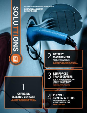
SOLUTTIONS
ISSUE 3, FOURTH QUARTER 2020, TRANSPORTATION
INNOVATION AND IDEAS IN ELECTRONICS
2
BATTERY MANAGEMENT FOR ELECTRIC VEHICLES BY DERMOT BYRNE, DIRECTOR INDUSTRY MARKETING, TRANSPORTATION, TTI EUROPE
3 1 CHARGING ELECTRIC VEHICLES BY DERMOT BYRNE, DIRECTOR INDUSTRY MARKETING – TRANSPORTATION, TTI EUROPE
REINFORCED TRANSFORMERS HOW TO SELECT THE RIGHT ONE FOR HIGH VOLTAGE ENERGY STORAGE APPLICATIONS A BOURNS APPLICATION NOTE
4
POLYMER T599 CAPACITORS PROVIDE EXTENDED LIFE AUTOMOTIVE SOLUTIONS A KEMET BLOG POST
The New Partnership for Automotive Connectors
TTI and TE Connectivity Shift Your Supply Chain into High Gear Now get all the performance you need from TE Connectivity (TE) automotive connectors through the unmatched reliability of a TTI supply chain solution. TTI now stocks a broad and deep inventory of TE products for the automotive industry including: • Powertrain Systems • Body and Chassis Systems • Safety and Security • Driver Information and Infotainment • Hybrid and Electric Vehicles • Tooling and More Now access the full advantage of specialization through our network of North American branches, with local product expertise backed by our Transportation Business Unit’s regional sales engineers, supported by the resources of TE. For more information contact your local TTI Specialist.
1.800.CALL.TTI tti.com
Learn More
TE Connectivity and TE connectivity (logo) are trademarks ISSUE 3 | FOURTH QUARTER 2020 | TRANSPORTATION 2
WELCOME TO SOLUTTIONS ISSUE 3, FOURTH QUARTER 2020, TRANSPORTATION
CONTENT 1
CHARGING ELECTRIC VEHICLES
BY DERMOT BYRNE, DIRECTOR INDUSTRY MARKETING – TRANSPORTATION, TTI EUROPE
2
BATTERY MANAGEMENT FOR ELECTRIC VEHICLES BY DERMOT BYRNE, DIRECTOR INDUSTRY MARKETING, TRANSPORTATION, TTI EUROPE
3
REINFORCED TRANSFORMERS HOW TO SELECT THE RIGHT ONE FOR HIGH VOLTAGE ENERGY STORAGE APPLICATIONS A BOURNS APPLICATION NOTE
4
POLYMER T599 CAPACITORS PROVIDE EXTENDED LIFE AUTOMOTIVE SOLUTIONS A KEMET BLOG POST
SoluTTIons is a regular publication of TTI, designed to bring clear, current information about the rapidly changing world of electronic design to engineers and procurement professionals in the electronics industry. Sourced from industry insiders and thought leaders, these case studies, white papers and marketing intelligence overviews are selected to be informative and thought provoking. Specific focus is given to transportation and industrial market categories.
CHARGING ELECTRIC VEHICLES
By Dermot Byrne, Director Industry Marketing – Transportation, TTI Europe
1
The electrification of vehicles is in full swing around the globe. As consumers, we are probably well aware of the various campaigns and initiatives being promoted to lessen our dependence on fossil fuel. These apply not only to our automobiles but to a wide range of vehicles on our roadsincluding commercial vehicles such as vans and trucks, and public transit vehicles such as buses and coaches, in addition to the many specialist vehicles used in agriculture and construction. Fundamental to the design of an electric-powered vehicle is the provision of a method of charging the vehicle’s batteries. This can be achieved two ways. First, EVs are equipped with an onboard charger that requires an AC mains input that is converted to DC for charging. This AC source is a dedicated EV charging station or a domestic AC outlet, located within the owner’s home or at their place of work. The other approach is to use a fast charging station that can deliver a high current DC to charge the batteries directly in the vehicle. Thanks to the Combined Charging System (CCS)/CharIN, a standard plug and socket arrangement found on most electric vehicles today, both methods of charging are possible. In this white paper we investigate the architecture of electric vehicle chargers, the types of functions involved and some of the many electronic components (MOSFETS, passives, rectifiers, magnetics) used in the design of on- and off-board charging systems. Interconnection is an essential part of provisioning an AC or DC supply, so example connectors are also highlighted from leading manufacturers such as Amphenol, ITT Cannon and TE Connectivity. This whitepaper covers the Combined Charging System & CharIN initiative and highlights the trend towards high current DC charging, and, in particular, the emerging trend of having even higher current capacity through liquid cooled cables. In the final part of the whitepaper, the emphasis is on high current charging stations, the design of a DC Fast Charger (TDK) and other connector standards that are starting to be used, including the CHAdeMO standard.
ISSUE 3 | FOURTH QUARTER 2020 | TRANSPORTATION 4
Discrete Semiconductors
FROM FOSSIL FUELS TO ELECTRIC VEHICLES
Optoelectronics Capacitors
The move away from fossil fuels for transport is accelerating with the increased introduction of electrically powered vehicles. Most are very aware of the high-profile manufacturers specializing in EVs such as Tesla, but the traditional vehicle suppliers are also in the game. Volkswagen, for example, plans to be producing around 50 different battery-electric models across its 12 auto brands by 2025. This is just cars; vans, buses, trucks, agricultural and construction vehicles are being increasingly battery powered as well, not to mention rail and even aircrafts from companies such as start-up Wright Electric with 180 seat airliners planned for 2027 for European short-haul flights. For vehicles, there are of course various degrees of electrification from full to mild/micro hybrid with differing architectures for battery charging and traction. There is normally the option to charge from a domestic or work-place AC source through an on-board charger or with high voltage, high power DC directly to the traction batteries from roadside or charging station outlets. Although quicker and more efficient, the high infrastructure cost of high voltage/power DC charging is unlikely to replace on-board AC input charging for the average user, so both are likely to feature for the foreseeable future. AC charging can still, however, be relatively quick - with 3-phase installations, where available, it can be up to around 22kW rating for standard industrial 400V/32A connections. Single phase domestic supplies are limited to around 3kW for standard 230V/13A outlets or 7.5kW for 32A. Given that EV batteries are sized between 10kWh and 40kWh (Tesla up to 100kWh), charging from these AC sources can be as slow as 10 hours or as quick as around 40 minutes for 30kWh batteries. As a guide, 30kWh equates to about 100 miles/160 km range. High voltage DC charging can be much faster, with outlets rated at 120kW giving a little more than 15 minutes charge time for 30kWh batteries with inefficiencies factored in, faster than a coffee break at a gas station. Table 1 gives a summary. Supply Type/ Charger Rating
AC/ DC
Rated Power kW
Time to Charge 10kW
Time to Charge 30kW
Standard 13A Socket
Slow
AC
3.0
3h 20m
10 hours
Single ph 16A
Slow
AC
3.7
2h 40m
8 hours
Single ph 32A
Fast
AC
7.4
1h 20m
4 hours
3-phase 16A/ph
Fast
AC
11
55 mins
2h 45m
3-phase 32A/ph
Fast
AC
22
27 mins
1h 22m
3-phase 60A/ph
Rapid
AC
43
14 mins
42 mins
DC
Rapid
DC
50
12 mins
36 mins
DC
Rapid
DC
120
5 mins
15 mins
Table 1: Approximate time to charge EVs from different sources (Source: Spirit Energy)
Relays
Resistors
Sensors
Inductors
Switches
Charging Couplers
Connection Systems Thermal Management Power Supplies Circuit Protection
TTI Stocks High-Voltage Components that Keep Your Production Rolling TTI Specialists have a broad and deep inventory of high-voltage transportation components stocked where you need them: • A 180,000 square-foot dedicated transportation component warehouse in Fort Worth, Texas • Our new 800,000 square-foot distribution center in Fort Worth, Texas • One of our seven proximity warehouses in Mexico’s major manufacturing centers ttiinc.com 1.800.CALL.TTI A Berkshire Hathaway Company ISSUE 3 | FOURTH QUARTER 2020 | TRANSPORTATION 5
Transformer
AC INPUT ON-BOARD CHARGERS There are various ways of implementing it1, but a first-generation single-phase AC input on-board charger block schematic might look like Figure 2, a relatively conventional switched mode power supply with power factor correction (PFC) – a scaled up version of a desktop PC power supply. The principle is that AC is rectified to high voltage DC, ‘chopped’ at high frequency which is then passed through a transformer whose output is scaled and rectified to high voltage DC for the battery, typically 400V. As with the lithium-ion batteries in your cell phone, the voltage applied, and the current allowed, has to be carefully controlled to prevent stress and maximize battery life/run time. The power factor correction stage is necessary to meet legislation which mandates that line current has to be taken sinusoidally which would not be the case otherwise. Three-phase AC input versions exist for some cars that are compatible, such as the Tesla varieties, and the supply is likely to be at a workplace rather than a domestic location which only has easy access to single-phase power. In practice, modern on-board chargers have evolved for better efficiency and to enable the possibility of bi-directional power flow. There are economic benefits available to users who allow utilities to draw power back from the car battery through the on-board charger ‘in reverse’. This allows a degree of grid energy storage that utilities can call upon, for example during the night when the car is plugged in with a full battery. As intermittent alternative energy sources such as solar and wind become a larger part of the mix, this forms a valuable grid ‘back up’ which utility suppliers will pay for. In a bi-directional converter, the rectifier and PFC stages merge typically into a ‘totem pole PFC’ arrangement with high voltage MOSFETs, perhaps from the Vishay range of automotive-qualified parts. MOSFETs are also used for the main conversion stage and to replace the output diodes in Figure 2 to form synchronous rectifiers, again necessary for bi-directional power flow. Vishay again has parts that might be used.
PFC* Circuit
Primary-Side Switching Circuit
Secondary-Side Switching Circuit
AC Volt.
Motor Inverter Shunt Regulator
PWM
PWM
High-Voltage Detention Circuit
PreDriver
Current Transformer
HEV/EV Secondary Battery
Isolator
Current Detection
PreDriver CAN
Main MCU
Thermistor
Current Detection
CAN Transceiver *PFC: Power Factor Correction
Figure 2: AC-DC on-board charger block schematic (Source: TTI)
Like semiconductors, passive components in the circuit need automotive AEC-Q qualification and range from resistors through capacitors, fuses magnetics and discrete components. The automotive environment is fraught with EMI problems, so extensive protection against voltage and current transients is needed. Littelfuse specializes in protection components in automotive applications with a range of devices for over-current, over-voltage and ESD protection. Capacitors, and all varieties of passive components are available from Vishay and AVX with AEC-Q qualification, and Nichicon, a company well known for their electrolytic capacitor offering, may also have suitable types. Magnetic parts such as transformers and inductors are often custom-made for the application, but standard parts are available from Vishay and Pulse. Planar types are often favored for their power density and ease of heatsinking – a particular problem in automotive where electronics is often sealed or even encapsulated to provide environmental protection.
Size and weight of the on-board charger are important issues – it is wasteful to use battery energy to pull around heavy electronics and cabin space is always maximized, so new semiconductor technology is being introduced in the form of ‘wide band-gap devices’ fabricated with Silicon Carbide (SiC) or even Gallium Nitride (GaN) materials. These devices can switch much faster than older Silicon (Si) types while keeping losses low. High frequency switching then allows smaller passive components; particularly magnetics. Smaller size and fewer losses directly lead to material savings in the form of smaller heatsinks and component costs while occupying a smaller footprint within the vehicle. SiC devices are available as diodes from TT Electronics for example, as well as switches. TT Electronics is also a source of AEC-Q qualified magnetics.
1 Ivan Subotic, Nandor Bodo, E. Levi , Boris Dumnic, Dragan Milicevic, Vladimir Katic: ‘Overview of fast on-board integrated battery chargers for electric vehicles based on multiphase machines and power electronics’: IET Electr. Power Appl., pp. 1–13: 24th August 2015 ISSUE 3 | FOURTH QUARTER 2020 | TRANSPORTATION 6
DC CHARGING STATIONS USE SIMILAR CONVERSION TECHNIQUES High voltage DC charging stations use a similar technology for converting utility power to the traction battery voltage, but at much higher power levels, Figure 3. The AC input will invariably be 3-phase, but bi-directionality is not a requirement, as roadside stations will always be required just to provide power to the vehicle. Efficiency of the charging process is, as ever, important for energy savings, but size and weight not as much so, as is the case for on-board chargers. The charging station may therefore use relatively low frequency switching for low losses using IGBTs as switches rather than MOSFETs. Figure 3: High voltage DC charging station (Source: ABB)
Keep Track of Speed with a Durable Sensing IC Honeywell’s Back Biased Hall-Effect Speed Sensor is AEC-Q100 Qualified and Highly Accurate • Zero Speed Capable • Short Circuit and Reverse Voltage Protection • Suitable for Select Automotive Applications In Stock Now, Contact Your Local TTI Specialist at 1.800.CALL.TTI or tti.com ISSUE 3 | FOURTH QUARTER 2020 | TRANSPORTATION 7
CONNECTIONS ARE KEY With so many EV manufacturers across the world with varieties of single-phase or three-phase AC and DC charging options with different power capabilities, connections between charging source and the vehicle have been an issue. In 2011, a Combined Charging System or CCS was proposed for a single connector pattern that could be used worldwide and is now formalized under IEC 62196, Plugs, socket-outlets, vehicle connectors and vehicle inlets – Conductive charging of electric vehicles. An association of car makers, suppliers and interested parties, the Charging Interface Initiative or CharIN2 was also set up to promote CCS. The first CCS compliant charging stations were rated at 50kW, but that was increased to 150kW in 2015 with plans for 350kW and perhaps higher in the future. The features of CCS include communications over a dedicated connection, the Control Pilot contact (CP), which ensure that connectors are fully mated before charging starts and that the source and vehicle capacities match. Basic signaling (BS) according to IEC 618511 uses a Pulse Width Modulation (PWM) signal to achieve simple functions while High Level Communication (HLC) based on DIN 70121 and the ISO/IEC 15118 series allows for more complexity such as scheduling of the charge rate for grid load-balancing. There are other competing standards for DC charging connections: CHAdeMO3 in Japan and a GB/T standard used in the important Chinese market. Tables 2 & 3 (Source: Wikipedia3) summarize CCS specifications. CCS 1.0 is current and CCS 2.0 is the next version for higher power and more features.
Feature
CCS 1.0
CCS 2.0
Power
< 80kW
< 350kW
Voltage
< 400V
200-1000V
Current
< 200A
< 500A
Vehicle Connector
Combo 1 or 2 (IEC 62196-3)
Combo 1 or 2 (IEC 62196-3)
Vehicle Intel
Combo 1 or 2 (IEC 62196-3)
Combo 1 or 2 (IEC 62196-3)
Charging Communication
High Level Communication: • DIN SPEC 70121:2014
High Level Communication: • DIN SPEC 70121:2014 (< 350kW) • ISO/IEC 15118-2:2014 ED1 (< 350kW) • ISO/IEC 15118-3:2015 ED1 (< 350kW)
Load Balancing
Reactive
Reactive and Scheduled
Charge Authorization Mode
External Payment
External Payment and/or Plug and Charge (mandatory from 2020 on)
Charging Station
IEC 61851-23
IEC 61851-23
Table 2: CCS system specifications for DC charging
Feature
CCS 1.0
CCS 2.0
Vehicle Connector
Type 1 or 2 (IEC 62196-2)
Type 1 or 2 (IEC 62196-2)
Vehicle Intel
Type 1 or 2 (IEC 62196-2) Combo 1 or 2 (IEC 62196-3)
Type 1 or 2 (IEC 62196-2) Combo 1 or 2 (IEC 62196-3)
Charging Communication
Basic Signaling: • IEC 61851-1:2010 ED2
Basic Signaling: • IEC 61851-1:2010 ED2
High Level Communication: • ISO/IEC 15118-2:2014 ED1 • ISO/IEC 15118-3:2015 ED1
High Level Communication: • ISO/IEC 15118-2:2014 ED1 • ISO/IEC 15118-3:2015 ED1
With Basic Signaling Only: • Reactive
With Basic Signaling Only: • Reactive
Load Balancing
With High Level Communication: With High Level Communication: • Reactive and/or • Reactive and/or • Scheduled • Scheduled Charge Authorization Mode
With Basic Signaling Only: • External Payment
With Basic Signaling Only: • External Payment
With High Level Communication: With High Level Communication: • External Payment and/or • External Payment and/or • Plug and Charge • Plug and Charge Charging Station
IEC 61851-1
IEC 61851-1
Table 3: CCS specifications for AC charging 2 https://www.charinev.org 3 https://www.chademo.com ISSUE 3 | FOURTH QUARTER 2020 | TRANSPORTATION 8
Inlet/Connector
Type 1
Combo
AC Charging Single Phase
Does not mate
AC Charging Single Phase
DC Charging
Type 1
Combo
Table 4: Mating options for Type 1 and Combo 1 couplers Inlet/Connector
Type 2
Combo 2
AC Charging Single Phase or Three Phase
Does not mate
AC Charging Single Phase or Three Phase
DC Charging
Type 1
Connector types stated in the tables are ‘Type 1, Type 2 and Combo 1, Combo 2. CCS originally was based on Type 1, a North American standard for single-phase AC connection and Type 2, as described in European standard IEC 62196-2, able to charge with three-phase AC. For combined high voltage DC and AC charging, new connector designs were adopted: Combo 1 and 2 associated with Type 1 and 2. Power inlets on vehicles have all pins populated corresponding to the charge possibilities while couplers, the connectors on the charging cable, just have the pins fitted for that source: AC or DC. Invalid combinations such as a Combo 1 coupler and an AC only inlet do not mechanically mate. Tables 4 & 5 show the combinations. (Source - Wikipedia). Couplers and inlets must be very sturdy to withstand everyday outdoor use, so manufacturers such as Amphenol have designed their parts for more than 10,000 cycles (unloaded). Their Excel Mate CC -200A IEC Combo parts are rated for 63A AC and 200A DC with IP44 environmental protection rating (mated). Phoenix Contact has versions of both Type 1 and Type 2 inlets rated up to 32A/480V three-phase and 200A/850V DC while Aptiv (formerly Delphi) has a wide range of automotive connectors including Type 1, Type 2 and versions for the Chinese GB/T standard. TE Connectivity is another major player in the market.
Combo
Table 5: Mating options for Type 2 and Combo 2 couplers
ISSUE 3 | FOURTH QUARTER 2020 | TRANSPORTATION 9
FUTURE CONNECTOR AND CABLE TECHNOLOGY Consumers want ever-faster charging rates, so charger powers of 500kW (0.5 MW) are planned, giving potentially 60 miles/100km of range within three to five minutes charging. This corresponds to a current of about 500A at 1000V DC presenting tough challenges to connector and cable design. A proposed solution developed by ITT Cannon is liquid cooling using an environmentally friendly hydrofluorether. The coolant is routed through the electrical cable, into the connector and around the contacts, providing such effective cooling that cable diameter and losses can be kept low, along with flexibility and low weight, for ease of handling. Versions are available for CCS Type 1 and 2. For all cables and connectors, safety is a prime concern, not only for mis-mating but also for insulation against the dangerous voltages present. Signaling in the connectors provides interlocks so that power is not applied until the connector is fully mated, sealed and with contacts then inaccessible. Connector manufacturers have to guarantee this level of safety even in the potentially harsh environments of outdoor use worldwide. Well-known manufacturers such as those mentioned can be relied upon to give this guarantee with parts supplied through established distribution2.
THREE-PHASE FAST DC CHARGERS The fractional-megawatt charging rates proposed cannot practically be supplied as AC to vehicles since the on-board AC-DC converter would be prohibitively large and expensive. DC input straight to the battery through an on-board charge controller is the only solution. Domestic or curb-side fast chargers with three-phase input and DC output are often modular in construction so that capacity can be added as necessary. The Tesla design for example, has more than ten, 10kW power units to achieve
>100kW. The design might look like Figure 4, typically with some blocks common to the ‘stack’ such as AC-DC rectification, EMI filtering and protection such as contactors to rapidly connect and disconnect power under fault conditions. The main isolation and conversion stage noted as ‘DC-DC HF Rectifier’ is duplicated to achieve the desired power level and will typically be a full bridge resonant topology for maximum conversion efficiency. Output rectifiers although shown diagrammatically as diodes, will often be MOSFETs configured as synchronous rectifiers, again for the lower losses incurred: a 20kW module at 400V DC output will source 50 amps which would cause around 100W dissipation in a regular diode bridge.
As with on-board chargers, power factor correction is necessary for efficiency and statutory reasons and will again be typically a ‘totem pole PFC’ arrangement, which effectively combines AC rectification with the switches required for power factor control, minimizing losses. EMI filtering is an important feature as, again, there are statutory limits to comply with. TDK has a wide range of passive components that find application in this circuit from EMI suppression components such as chokes and X/Y capacitors through power capacitors for energy storage and snubbers, to protection components such as sensors and high voltage contactors. 2 https://www.charinev.org 4 https://en.wikipedia.org/wiki/Combined _Charging_System 5 www.ttieurope.com
Figure 4: Modular three-phase fast charger outline (source TDK)
ISSUE 3 | FOURTH QUARTER 2020 | TRANSPORTATION 10
CONCLUSION The comparisons between re-fueling an internal combustion engine and an electric vehicle could not be more extreme. Both involve a hazardous operation but with EVs, there is the added complication of AC or DC charging, differing power levels and the different standards of connectors on the vehicle and charging station. The CCS system with its Combi connectors is allowing convergence with a degree of future-proofing, with innovations such as liquid cooling of cables and connectors. The technology advances hold out the possibility of significant charge/range being available, with automated payment, within minutes – about the same time as it might take to fill a tank with gas, grab a coffee and queue to pay. Major manufacturers have made components for both on- and off-board charging systems available with distributors such as TTI providing application support and stockholding.
ISSUE 3 | FOURTH QUARTER 2020 | TRANSPORTATION 11
BATTERY MANAGEMENT
For Electric Vehicles
By Dermot Byrne, Director Industry Marketing, Transportation, TTI Europe
2
Governments, car makers, and markets all agree that the age of the electric vehicle is here. Global sales of hybrids and EVs are expected to surpass those of ordinary internal-combustion vehicles by 2038, and achieve cost parity even sooner, by 2025. Electrification of public transport, such as buses, also represents an exciting development in low-carbon transportation. Markets are moving quickly, and so, too, is the technology. In particular, battery technology has perhaps the greatest potential to unlock rapid improvements in drivability, recharging times, and cost of ownership. While chemists and materials scientists strive to deliver new compositions and electrode structures that can store more energy, charge and discharge more quickly, and reduce size, weight, and cost, one subsystem has a critical role in unleashing the maximum potential of the battery and ensuring long-term reliability: the Battery-Management System, or BMS. No research into exotic materials or processes is needed to deliver a cutting-edge BMS that is capable of managing and protecting the most advanced batteries in use today, or expected in the near future. A smart BMS can be realized using familiar components and design techniques, although it is worth mentioning that experts see the compute capability of the BMS rising quickly to manage an increasing variety of parameters with greater precision. While the core BMS functions are well known and relatively straightforward to implement using standard ICs and/or microcontrollers, many additional sensing and protection components are needed to complete the design. These should be carefully selected to withstand the automotive environment and operating voltage/current ratings, and ensure proper protection for the battery, the BMS circuitry, and humans who need to come into contact with the system. This whitepaper describes those components and their role in maximizing the performance of today’s electric vehicles to help secure a lower-carbon tomorrow.
ISSUE 3 | FOURTH QUARTER 2020 | TRANSPORTATION 12
THE BATTERY
THE BATTERY AND BMS IN CONTEXT
The battery is arguably the most important part of an electric vehicle: its performance defines critical dynamic parameters such as electric driving range and acceleration, it constitutes a significant proportion of the vehicle’s weight, especially in fully electric (non-hybrid) vehicles, and it also contributes significantly to the vehicle’s overall cost. Moreover, while research in fields such as electric motors and power electronics is yielding only incremental improvements, the development of new battery chemistries, and anode and cathode material technologies offer hope for greater improvements in driving range, recharging time, and the price of EVs compared to conventional vehicles.
Figure 1 illustrates the major parts of a H/EV battery pack, showing the general layout of batteries, connectivity, control circuitry, and packaging. It's worth noting that electric-vehicle technology is still relatively young and evolving quickly. A standard approach to battery-pack construction and BMS architecture has not yet emerged.
A good battery-management system (BMS) is critical for maintaining condition and optimizing performance to maximize the vehicle’s dynamic abilities, ensure reliability, and deliver the best possible overall ownership experience.
In addition, there are various approaches to cooling of the battery, ranging from heatsinks and forced-air cooling with fans, to liquid cooling with the familiar expedient of a front-mounted radiator in the nose of the vehicle. Tesla, for example, has adopted liquid cooling and, indeed, builds batteries using hundreds of individual standard-size Li-ion cells to maximize the surface area that can be exposed to the coolant channels. Other approaches advocate flexible battery pouches, or custom shapes, to help achieve the desired overall vehicle packaging. The battery pack is typically organized as groups of cells connected in series to create a module. Modules are then connected in series to reach the required terminal voltage, which may be 380V or more. Extra modules are added in parallel to achieve the desired capacity, which is usually quoted to the user in kilowatt hours (kWh). The battery capacity is restricted by factors such as the size and layout of the vehicle, weight, as well as cost. As the current dominant battery chemistry for consumer and battery-EV applications, the cost of lithium-ion batteries for automotive use has fallen significantly in recent years and is now down to $156/kWh at the end of 2019; expected to fall to $100/kwh by 2023. (Source: Green Car Reports).
The BMS has multiple roles, including continuously controlling the charge/ discharge rate and monitoring the state of charge (SoC), managing the balancing of cell voltages, and providing essential safety features such as over-temperature and over-discharge protection, safety isolation of critical electrical subsystems, and the ability to disconnect the battery to allow servicing of the vehicle. Advanced BMS features may include OBD-II support to simplify fault diagnostics, CAN-bus integration, data logging, and support for firmware upgrades in the field. The BMS must capture data and distribute commands on a cell-by-cell basis. In addition to the underlying processing and communication, an array of sensing, isolation, protection, and signal-conditioning circuitry is needed, to enable accurate detection of the battery condition under any and all operating conditions, to manage the battery and integrate the system within the overall vehicle electronic infrastructure. In practice then, the BMS is multi-faceted and complex, bringing together power switches, temperature and voltage/currentsensing elements, filtering and decoupling, isolation transformers, safety interconnects and others, to support the major functional blocks that include charge-control, fuelgauging, balancing, data-processing and communication. The amount of processing in the BMS, to keep the battery in control and optimize performance and reliability, is increasing rapidly as the batteries become more sophisticated and demand more intensive control and management.
Figure 1: Main components and general layout of H/EV battery pack (Source: Audi Technology Portal)
ISSUE 3 | FOURTH QUARTER 2020 | TRANSPORTATION 13
MONITORING AND PROTECTING THE BATTERY
On-Board Charger PA 434xNL AC Input
The role of the BMS is to maintain the condition of the battery on a cell-by-cell basis to ensure safety and long-term reliability, as well as optimal performance. Ultimately, the BMS controls charging and discharging via two MOSFETs associated with each cell. Based on measured cellcondition data such as state of charge, terminal voltage and temperature and the power requested by the driver – moderated by vehicle control systems such as traction control – the BMS adjusts the charge and discharge rate of each cell through PWM control of these MOSFETs. The MOSFET control circuit needs to be separated from the battery, which can be achieved using a high-isolation transformer such as the Pulse Electronics PH9185.XXXNL series.
AC/DC
PA 1005QNL
PFC
DC/DC
HV Battery
M PH91 85NL
Battery Charger and Monitor
HM1188NL Battery Charger and Monitor Automotive Interface CAN BUS / Ethernet Battery Charger and Monitor
BMS Controller
ESS Interface Ethernet
The circuitry for voltage and temperature sensing and monitoring the battery stateof-charge, often using Coulomb counting, is located close to each cell and communicates with main battery-management functions across a serial communication link such as an RS-485 bus. For safety, the monitoring/ control circuitry for each cell is isolated using a bus-isolation transformer such as Pulse’s HM1188NL (Figure 2). Figure 2: Bus isolation using a transformer such as the Pulse HMI1188N (Source: Pulse Electronics) https://www.pulseelectronics.com/news/2017/09/using-battery-management-systems-for-morereliable-evs-and-phevs/
ISSUE 3 | FOURTH QUARTER 2020 | TRANSPORTATION 14
Cell balancing is an important part of the monitoring and protection mix, to equalize the loading placed on the cells and prevent thermal runaway that can result from underor over-voltage conditions on any individual cell. Sensing is needed on a per-cell basis to let the system apply an equalizing charge, and can be implemented using a component like the PA4334 series inductor by Pulse to help identify a drop or increase in cell voltage. Pulse also has a series of surface-mountable flyback transformers for handling balance-charge transfers, as well as push-pull transformers that help prevent cell-voltage imbalances due to loading. For battery charge monitoring, Vishay offers an alternative in its WSLS Power Metal Strip shunt resistors. These 6W-rated sense resistors are produced using a process that allows extremely low resistance values down to 0.0003 ohm that permit high accuracy at a low cost. Maintaining consistent cell temperature is essential to ensure safety and longevity. Over-charging or excessive power draw can raise the cell temperature. The temperature of the battery pack can be sensed at various points, such as at individual cells as well as interconnects and detecting coolant temperature, to let the system acquire a complete assessment of battery health. Detecting over- or under-temperature at any individual cell enables the system to restore the correct temperature by, for example, suspending regenerative charging, or limiting the output current.
The battery temperature can be sensed at multiple points to establish an accurate and detailed picture of the environment and the condition of the battery. These include not only the temperature at the surface of the cell but also the external battery casing, busbar connections, and temperature at various points in the liquid-cooling system, if featured. Sensing temperature in differing locations such as these presents a variety of challenges, such as extreme space limitations for measuring cell surface temperature, or insertion of temperature probes into the liquid coolant pipes. Amphenol has a variety of temperaturesensing options designed explicitly for automotive BMS sensing applications, including extremely small sensors designed for insertion between cells and positioned against a flat surface, as well as sensors for external mounting on the battery case, or permanent connection to high-current busbars. Among these, ring terminal temperature sensors that contain an NTC thermistor and are screw-fixed in position (Figure 3) can perform surface- temperature or terminaltemperature measurement and allow easy attachment of a lead wire or connector.
Figure 3: Ring terminal sensors are used to measure surface temperature or temperature at busbar connections. (Source: Amphenol)
Figure 4: Amphenol CTS temperature sensors are inserted in pipes or unions to sense the coolant temperature directly (Source: Amphenol) https://www.amphenolsensors.com/en/thermometrics/assemblies/3292-coolant-temperature-sensor
Also available are thin-film temperature sensors that must conform to non-flat surface topology, as well as Thermometric coolant temperature sensors (CTS) that can be inserted in inlet or outlet unions (Figure 4).
ISSUE 3 | FOURTH QUARTER 2020 | TRANSPORTATION 15
Module 1
Temp
5
Li Cells
Cell Balancing & Protection Cell Monitor
High Voltage Main Fuse
Cell Monitor
4
Module X
7
Cell Balancing & Protection Propietary
1
3
Contactor/ Main Switch
Sense Lines
MicroController
6
Daisy Chain I/F
Li Cells CAN Bus
Temp
Cell Balancing & Protection
Cell Balancing & Protection Sense Lines
Propietary
Cell Monitor
Cell Monitor
MicroController
6
6
BMS/ Charge Controller
Daisy Chain I/F c
2018 Littelfuse, Inc.
Figure 5: Essential protection for BMS circuitry against high-voltage/high-current hazards that pervade electric vehicles. (Source: Littelfuse) https://www.littelfuse.com/~/media/electronics/application_guides/littelfuse_automotive_electronics_applications_guide.pdf.pdf
PROTECTING THE BMS CIRCUITRY While the core role of the BMS is to protect the battery pack against potentially damaging imbalances and over-temperature conditions, its own circuitry must be protected against hazards that pervade the EV, such as high-energy transients and high-voltage discharges. These can occur at multiple locations, such as close to cells or battery modules, or at terminations of cables. Devices such as transient voltage suppressors (TVS), which are already proven to protect sensitive electronic equipment against over-voltages, are now available in AEC-Q100 certified families such as the Littelfuse TPSMC series, which have 1500W peak pulse-power capability and satisfy IEC 61000-4-2 and IEC 61000-4-4
Location
Protection Device Type
Properties
1
Overcurrent / SMD fuse
Normal overcurrent protection up to about 8A. High-voltage protection up to 450V and 5A.
2
Overcurrent / fuse in wiring harness
Ceramic fuses up to 10A or greater, with high interrupt rating.
3
Overvoltage / TVS diode
Peak pulse capability up to 5000W
4
ESD / diode array
Uni/bi-directional 30/30kV ESD protection
5
Overvoltage / TVS diode
Designed to protect sensitive electronic equipment
6
ESD / diode array
Industry-standard CAN-bus protection
7
Main high-voltage battery fuse
EV-specific high-current fuse. Rated 60-250A/500V
Table 1: General summary of protection devices in figure 5.
specifications. There are also AEC-Q101 qualified ESD protection diodes, such as the Littelfuse AQ1 series, which are ideal for protecting the connections between individual cell-monitoring units, as well as families such as the SM24CANA TVS Diode Array that provides industry-standard protection for CAN bus infrastructure.
Figure 5 identifies the major connections between functional parts of the BMS, which require protection against potentially damaging over-voltage, over-current, and ESD events. Table 1 clarifies the component types selected and their key properties.
ISSUE 3 | FOURTH QUARTER 2020 | TRANSPORTATION 16
PROTECTING PEOPLE High-current, high-voltage connectivity is obviously needed between the battery system and the inverter that controls and drives the traction motor. While high reliability, low contact resistance and protection against ingress and corrosion are extremely important, so, too, is a reliable and robust means of disconnecting the battery to enable the vehicle to be serviced safely, or if necessary for the safety of occupants or responders in the event of an accident. Suitable battery connectors, therefore, are designed to allow fast and easy disconnection and reconnection without
compromising the physical integrity or reliability of the connector assembly, or the integrity of the electrical interconnections. Personnel should also be protected against contact with battery-side terminals that remain at high voltage while the connection is unmated.
Figure 6: The manual service disconnect is safe and easy to use by service staff and emergency response teams.
An example is the TE Connectivity AMP+ Manual Service Disconnect (Figure 6), which features a two-stage finger- actuated lever system that allows the high-voltage contacts to be separated without using tools, and is designed to USCAR-2, USCAR-37, and IEC 60529 standards and specifications. The battery-pack HV cables are prevented from short-circuiting, and HV contacts are always finger safe.
CONCLUSION The battery is the subject of some of today’s most important advancements in electric vehicle technology, aiming to extend driving range, reduce charging duration, enhance performance, reduce cost of ownership, and drive cost parity between EVs and conventional combustion-engine vehicles. The BMS has a critical role in maximizing the battery-pack performance under all driving and usage conditions. A well designed BMS detects possible threats to the battery, and the onset of sub-optimal performance through imbalances or overtemperature. It comprises multiple layers of safety and protection mechanisms, at the cell, module, and system levels to preserve the battery, maximize performance and reliability, with robust and reliable disconnection provisions to protect users, service personnel, and first responders in the event of an accident. On the other hand, the BMS itself requires robust protection against potentially damaging electrical hazards such as ESD and overvoltage or overcurrent events.
ISSUE 3 | FOURTH QUARTER 2020 | TRANSPORTATION 17
REINFORCED TRANSFORMERS
How to Select the Right One for High Voltage Energy Storage Applications A Bourns Application Note
3
Providing isolated low voltage bias power to ICs such as microcontrollers, analog-to-digital converters, isolated gate drivers or voltage monitoring ICs in high voltage systems is usually accomplished with an isolated DC-DC converter. If the high voltage system is spread out over several modules, the architecture may call for a parallel DC bus on the low voltage side with multiple isolated low power DC-DC converters for each module. Because it is used multiple times in this scenario, an efficient and cost-effective topology is the best approach. This application note highlights the design benefits of using push-pull transformers that are proven solutions for these situations. Used as an example is the BournsÂŽ Model HCTSM8 series transformer, which is AEC-Q200 compliant and available with a wide range of turns ratios as standard. Multiple turns ratios are an important feature enabling the same basic circuit topology to be replicated across a system with the same components and PCB layout. With a transformer series like the Model HCTSM8, designers are able to select the right reinforced transformer part number based on the specified output voltage for powering a microcontroller or an isolated IGBT gate driver.
ISSUE 3 | FOURTH QUARTER 2020 | TRANSPORTATION 18
equalizing the imbalance. Currents (A) 0.3 0.2 0.2 0.1 0.1 0.0
0.0
0.5
1.0
1.5
2.0
2.5
3.0
3.5
4.0
4.5
Time (µs)
Pin 1 M1
Vin
L1
L3
L2
L4
M2
Figure 1.
C1 R1
M1
1 μF Vin D2
L1
L3
L2
L4
C1 R1 1 μF
M2
Illustration of the operation of a push-pull converter with the red and green lines indicating output current
Figure 1: Illustration of the operation of a push-pull converter with the red and green lines indicating output current
s.com
WHY PUSH-PULL TRANSFORMERS ARE AN OPTIMAL CHOICE ELECTRICAL ADVANTAGES Push-pull transformers are known to operate well with low voltages and low variations in input and output. This characteristic is ideal for a microcontroller bias or gate driver IC that has constant power levels and input voltages. Unlike typical flyback and forward topologies, the push-pull topology offers high efficiency at a stable input and output current. Any variations in input and output current tend to waste energy as the power dissipated in the switches remains constant.
In addition, flyback transformers can cause EMI problems and often require closed loop control for stable operation even though they can efficiently handle wide input ranges. Conversely, a push-pull transformer can operate very simply in open loop. Compared to the number of components required for closed loop control, open loop control only requires a combination of a driver with a fixed duty cycle along with two MOSFETs, a transformer whose turns ratio is selected to suit the desired output, two Schottky diodes, and two ceramic capacitors. In fact, the driver can be a microcontroller that may already be in use. If a microcontroller is used as the driver, then additional NPN transistors and resistors are necessary to provide the gate drive of the push-pull MOSFETs.
07/20 • e/IC2075
There are other reasons that justify the choice of a push-pull transformer. The shape of the output current is regular and not pulsating, which tends to stress the diodes and capacitors. For a relatively low current solution, diodes offer a cost-effective addition that can help ensure compensation and balancing of the transformer. If the magnetizing current is imbalanced, the additional current in the winding will cause the drain-to-source resistance of the driver MOSFET to increase. This increases the voltage drop across the MOSFET and reduces the voltage across the winding, thereby equalizing the imbalance.
ISSUE 3 | FOURTH QUARTER 2020 | TRANSPORTATION 19
MECHANICAL BENEFITS Space-Saving Specifying a push-pull transformer for low voltage applications offers several spacesaving benefits. They typically are offered in a smaller footprint than flyback transformers. And because push-pull transformers are designed as “pure” transformers, they usually have physically smaller ferrite cores compared to flyback transformers. Plus, there is no gap required in the ferrite core of a push-pull transformer, and, therefore, the effective permeability remains high and the magnetizing inductance can be quite high for a low number of turns. Given a sufficiently high switching frequency and low DC voltages, the flux generated (Volt Seconds per Turn) remains well below the saturation point. Contrast this result with the split ferrite core in a flyback transformer where more turns are needed to ensure the current does not saturate the transformer. If there are tight space considerations and restrictions, the DC resistance will inevitably increase with the higher number of turns, resulting in reduced efficiency. It is advised to look for a push-pull transformer with a toroidal core. What makes them a good choice is that there is no need for a gap, and a toroidal core www.bourns.com is well known for providing good coupling between windings. This is because the flux has a short distance to travel and there is little dispersion between windings. The relatively high inductance factor of a push-pull transformer with a toroidal core means it is possible to achieve high magnetizing inductances without a high number of turns. Plus, a coil former is not required as the wires are wound directly on the ferrite, which feature a high dielectric protective coating. Coil formers add extra space as does the fact that the ferrite split core is exposed on the top and bottom if the transformer is an SMD device.
1.9 (.075)
3.05 (.120)
1.2 (.047)
1.14 (.045) 3.00 (.118)
11.31 (.445)
DIMENSIONS:
Figure 2.
1.8 (.070)
25 (.984)
MM (INCHES)
Comparison between Bourns® Model HCTSM8 push-pull transformer and a typical split core transformer, both with 8 mm of creepage
Figure 2: Comparison between Bourns® Model HCTSM8 push-pull transformer and a typical split core transformer, both with 8 mm of creepage
A toroid core can be enclosed in a housing separating the core from the circuit board. This difference automatically minimizes the footprint on a PCB in high voltage applications where safety distances (creepage and clearance) are required as defined by the standards for insulation (IEC 60664) and communications equipment (IEC 62368) that mandate a specified distance between the high voltage hazardous side of the PCB and the low voltage side. If the core is exposed, the clearance will be significantly reduced which will need to be compensated by additional width or height of the plastic carrier.
Figure 2 shows a comparison in terms of dimensions between the Bourns® Model HCTSM8 transformer and a transformer with a split core such as an E13. The figure illustrates that the E13 solution requires 07/20 • e/IC2 90 percent more room on the PCB in order to meet the same isolation level of the Bourns® HCT transformer. Furthermore, the leakage inductance of a transformer with an extended bobbin needs at least 200 percent more space on the PCB compared to a transformer with a tightly coupled toroid, even with the primary wrapped around the outside of the housing.
ISSUE 3 | FOURTH QUARTER 2020 | TRANSPORTATION 20
Better Insulation The Bourns® Model HCTSM8 has reinforced insulation, which according to standards must consist of either triple insulated wire (three separate layers of insulation on the wire) on one winding or insulation on both windings (double insulation). Double insulation is not efficient from an electrical point of view. The time to strip the insulation from the start of the coil during the winding process will be twice that of a triple insulated transformer. The effective space for conductors is reduced in a double insulated system as both coils have at least 0.08 mm of insulation compared to 0.02 mm for pure magnet wire with enamel. The time required to wind a toroid with insulated wire is higher compared to enamel coated wire. Therefore, double insulation is less efficient and more expensive. However, to some customers double insulation has the advantage of offering real redundant insulation compared with triple insulated wire.
Using the HCTSM8 series transformer example, the secondary winding consists of FIW (fully insulated wire), which is considered as strong as triple insulated wire but without safety agency recognition (for many types). This is particularly relevant in a transformer with a toroidal core. The concern is the effect of triple insulated wire which could degrade and cause a short to the core and also from the core to the noninsulated wire. This risk can be mitigated using FIW wire on the secondary side. Maximum Creepage/Clearance The Bourns® HCTSM8 push-pull transformer makes full use of the enclosure around the ferrite core to maximize creepage and minimize the footprint. The core is not visible from the pins of the design so the clearance pin to core will be measured up the wall of the device and down the joint between the lid and the side wall. The effective tracking distance over the insulated wire from pin to
core is maximized by running the insulated wire around the outside of the component. By using this breakthrough design that features a press fit of the lid against side wall and the wraparound insulated wire, the Model HCTSM8 series can obtain a creepage and clearance of 8.0 mm despite having a nominal height of just 6.5 mm and a distance from pad to pad on the PCB of 11 mm max. In addition, the Model HCTSM8 uses plastic material classified as Class I, which means it is the least conductive of all plastics to high voltages. It features triple insulated wire on one winding (primary). Consequently, by taking 8.0 mm as creepage and clearance distance and consulting table F.4 of IEC 60664, this transformer offers a working voltage of 800 Vrms. As a result, inverters and battery packs with rms voltages of up to 800 Vrms requiring reinforced insulation could use the HCTSM8 for the following two energy storage applications: A. Isolated DC voltages for a gate driver for an IGBT or SiC MOSFET B. Isolated DC power for a microcontroller or voltage monitoring IC or transceiver
Figure 3: Illustrates the construction of the Bourns® Model HCTSM8 transformer with a toroidal core showing the lid and primary wire wrapped around the housing to extend the distance from the pins to the core
ISSUE 3 | FOURTH QUARTER 2020 | TRANSPORTATION 21
5V 1 T1 6
TYPICAL APPLICATION USAGE
1 2 C7 C8 10 μF 10 μF
3
U1 D1
GND
VCC
GND
1
5
2
4
D2 SN6501QDBVRQ1
1
2
3
C2 0.1 μF
4.7 k R7 2 U2
1:3.9
GND
APPLICATION APPLICATIONNOTE NOTE
4
R2
C3 C4 C5 4.7 μF 4.7 μF 0.1 μF
3
5
3
+15 Vb
BAV70-E3-08 D1
Comb
3.01 k C9 0.1 μF R10 4.99 k
R53
Gnd_B
To generate plus and minus voltages for a 0 -4 Vb gate driver, a circuit configuration similar to that shown in Figure 4 represents why Figure 4. Typical circuit generating diagram showing plus and minus voltages when using the Model Bourns® Model HCTSM8 is a valid solution. HCTSM8 Transformer transformer How to Select the Right Reinforced for High Voltage Energy Storage Application In this example, the device is driven by Figure 4: Typical circuit generating diagram showing plus and minus voltages when using the an integrated Texas Instruments SN6501 Model HCTSM8 transformer push-pull driver. The Texas Instruments device operates at a high frequency (400 kHz) and has a fixed duty cycle (50 Typical Application Usage (Continued) percent). The output relationship in a push-pull driver with Input VinHCTand Output HCT Series Series HCTSM80308BAL Efficiency HCTSM80308BAL- -Load LoadCurrent Current vs vs Efficiency Vout and duty cycle D is as follows:
How to Select the Right Reinforced Transformer for High Voltage Energy Storage Applicatio Typical Application Usage (Continued) 90 %90 %
Vout = 2 x D x n x Vin where n is the turns ratio from secondary to primary. www.bourns.com
80 %80 %
Figure 5 shows the efficiency of a circuit when using Model HCTSM80308BAL, which is an ideal solution to provide the 15 V needed for an isolated gate driver IC. The optimum operating point for this application is between 100 mA and 150 mA output current. Figure 6 shows the test circuit used to validate the HCTSM8 series and highlights the test board and equipment used for calculating overall power efficiency.
www.bourns.com
60 %60 %
Efficiency (%)
Efficiency (%)
Model HCTSM8 has 11 different standard turns ratios. Because the Texas Instruments SN6501 device uses internal MOSFETs whose maximum voltage rating is 5V, the Vin cannot exceed this level. And in order to generate 12V which is required to switch on an IGBT, it requires a turns ratio of 2.5. It is not possible to push D beyond 50 percent in a push-pull transformer as the time to magnetize and demagnetize the core must be balanced or saturation will occur. The negative voltage can also be generated from the same transformer by attaching a shunt reference between the ground rail and a negative output. Given that the Model HCTSM8 series is a catalog product with AEC-Q200 compliant quality levels, it provides an efficient and costeffective isolated power source compared to a customized transformer. A customized solution typically requires multiple outputs involving soft tooling and hard tooling, as well as the additional costs to develop.
07/20 • e/IC2
70 %70 % 50 %50 % 40 %
40 %
30 %
30 %
20 %
20 %
10 %
10 % 0%
0% 0
0
50
100
50
100
150
200
150
200
Load Current (A)
250
250
300
300
Load Current (A) Figure 5.
Graph demonstrating the efficiency of the Bourns® Model HCTSM8 transformer with 3:8 turns
withdemonstrating the Texas Instruments Model SN6501 driver Model HCTSM8 transformer with 3:8 turns the efficiency of the Bourns® Figure 5. Graph with the Texas Instruments Model SN6501 driver ® Figure55:shows Graph the demonstrating of the Bourns Model HCTSM80308BAL, HCTSM8 transformer which with 3:8isturns Figure efficiencythe of efficiency a circuit when using Model an ideal with the Texas Instruments Model SN6501 driver solution to provide the 15 Vof needed forwhen an isolated driver IC. The optimum which operating Figure 5 shows the efficiency a circuit usinggate Model HCTSM80308BAL, is anpoint idealfor this application is between 100 mA and 150 mA output current. solution to provide the 15 V needed for an isolated gate driver IC. The optimum operating point fo
this application is between 100 mA and 150 mA output current. Fluke 179 Multimeter
Fluke PWR 179 GND Vcc1 Multimeter 1 2 B1PWR GND Vcc1 PWR1 1 C1 C2 2 B1 GND 2 PWR5 V1 Input GND 2
10 μF 0.1 μF
C1 C2 10 μF 0.1 μF GND1
5 V Input GND1
Figure 6.
1 T1 6 U1 4 GND U15 GND
D2 VCC
3 Vcc1 2
1 T1 6 2
5
MBR0520LT1G D1
MBR0520LT1G
D1
Vcc2
BK Precision 8540 1 PWR Vcc2 BK Precision 8540 2 GND
1 PWR
DC 150 W C3 C4 C5 2 GND Load Electronic 0.1 μF 0.1 μF 10 μF
3 D2D1 1Vcc1 4 GND DC 150 W 2 5 2 C3 C4 C5 5 SN6501DBVR D2 VCC 3 4 Electronic Load GND 1 C6 0.1 μF 0.1 μF 10 μF C7 HCTSM80304BAL MBR0520LT1G D1 GND2 SN6501DBVR 1 μF 0.1 μF D2 3 4 C7 HCTSM80304BAL MBR0520LT1G C6 GND2 GND1 1 μF 0.1 μF
GND1 Model HCTSM8 Series has been fully validated
Figure 6: Model HCTSM8 Series has been fully validated Figure 6. 6 shows Model the HCTSM8 Series has been fully validated Figure test circuit used to validate the HCTSM8 series and highlights the test board and equipment used for calculating overall power efficiency.
Figure 6 shows the test circuit used to validate the HCTSM8 series and highlights the test board an equipment used for calculating overall power efficiency.
ISSUE 3 | FOURTH QUARTER 2020 | TRANSPORTATION 22
07/20 • e/IC2
is the criteria Bourns used when it defined the electrical isolation specification:
BMS TRANSFORMER SAFETY TESTING
Line to Neutral Voltage • 480 to 960
Overvoltage Category • Overvoltage Category I
The question of ensuring that the transformer’s insulation will remain intact from the tape in which it is delivered to the board and during the lifetime of the application is answered by complying with accepted industry standards. Bourns designed and tested its Model HCTSM8 series to survive identified solder reflow conditions and can be reflow soldered three times without degradation of the insulating wire. The insulation strength was tested using a Hi-POT tester applying 4 kVrms for up to 60 seconds. Shown in Figure 7 is the criteria Bourns used when it defined the electrical isolation specification: Determining the Overvoltage Category depends on where the power supply is located. If there is no risk of a transient from the mains hitting the power supply, such as where the voltage source is located relative to the battery, then the application may be categorized as Category I. If there is an isolated connection to the mains supply, it is permitted to move from Category II to Category I.
www.bourns.com The Hi-POT test is used to check the solid insulation in the transformer but it can also be used to verify that the clearances comply with the standard. Any signs of arcing or corona discharges will be a clear failure. The Model HCTSM8 is designed for 800 Vrms at a 2000 m altitude. For higher altitudes, the working voltage must be derated as the breakdown voltage or corona of air decreases as the air becomes thinner.
Transient Overvoltage/Required Withstand Voltage • Overvoltage Category I 250 V
Figure 7.
Electric Strength Test Voltage • Test for Basic Insulation Based on Withstand of 2500 V = 2.92 kV • Test for Reinforced = 160 % of Basic = 4 kV
Decision flowchart specifying Model HCTSM8 isolation test voltage
Figure 7: Decision flowchart specifying Model HCTSM8 isolation test voltage Determining the Overvoltage Category depends on where the power supply is located. If there is no risk of a transient from the mains hitting the power supply, such as where the voltage source is located relative to the battery, then the application may be categorized as Category I. If there is an isolated connection to the mains supply, it is permitted to move from Category II to Category I.
The Hi-POT test is used to check the solid insulation in the transformer but it can also be used to verify that the clearances comply with the standard. Any signs of arcing or corona discharges will be a clear failure. The Model HCTSM8 is designed for 800 Vrms at a 2000 m altitude. For higher altitudes, the working voltage must be derated as the breakdown voltage or corona of air decreases as the air becomes thinner.
07/20 • e/IC2
ISSUE 3 | FOURTH QUARTER 2020 | TRANSPORTATION 23
FUTURE TRENDS Working voltages of 1000 V and 1500 V for transportation applications, as well as energy storage in industrial installations, require isolation testing with various levels of test voltages according to the relevant standards as shown in Figure 8. The IEC 60664 standard also refers to using partial discharge testing to ensure there are no defects in the insulation such as tiny pinholes, which would expand over time under a strong electric field. In fact, complying with IEC 60664 requires that designs pass the standard of partial discharge if the electric field between primary and secondary exceeds 1000 V/mm and if the working voltage exceeds 750 V.
Working Voltage
Overvoltage
Clearance VeriďŹ cation
Solid Insulation
Solid Insulation Test
Example 1500 V
OV II
Impulse Test 8 kV
Reinforced
Hi-POT 6.4 kVrms 60 Seconds
A Higher Level of Protection from High-Voltage Hazards
Figure 8: Electrical insulation test voltages for a 1500 V battery
Automotive grade high clearance/creepage transformer designed for use with Texas Instruments push-pull converters for high-voltage isolation applications. Custom Devices Available for Use with Other Chipsets
In Stock Now, Contact Your Local TTI Specialist at 1.800.CALL.TTI or tti.com ISSUE 3 | FOURTH QUARTER 2020 | TRANSPORTATION 24
DESIGN ADVANTAGES This application note illustrates the advantages designers can leverage by using the Bourns® HCTSM8 series transformers for module hardware energy storage applications. The flexibility, efficiencies, low EMI and space-saving benefits present a compelling solution for these designs. The Bourns® HCT series has been tested and approved by Texas Instruments in their Model SN6501 and SN6505 series of pushpull drivers. As the range of applications for high voltage driven equipment in transportation and other markets increases, so too will the demand for stable, high quality and standardized isolated power designs in applications such as modules in high voltage battery or ultra-capacitor packs. Bourns offers 11 different fully tested and AEC-Q200 compliant Model HCTSM8 series push-pull transformer part numbers for the Texas Instrument drivers. Based on Bourns’ advanced power transformer design, the HCTSM8 series delivers the right combination of isolated power with low voltages for energy storage gate drivers, microcontrollers, battery management ICs and many more applications.
Flexibility
Very Efficient Design
Smooth Non-Pulsating Output Current
Minimum Footprint
• Standard part with 11 different turns ratios provides ease of mind concerning quality and flexibility allowing for output voltages of up to three times input voltages
• No requirement for expensive feedback winding or opto-isolator • Lower DC resistance than a flyback transformer with the same inductance
• Low EMI footprint compared to a flyback transformer • Can use lower cost ceramic capacitors and Schottky diodes
• No coplanarity concerns compared with extended split core bobbins • Up to 50% less surface area on PCB compared to split core
Figure 9: Presents the benefits of selecting a standard catalog transformer like the Model HCTSM8 series
ISSUE 3 | FOURTH QUARTER 2020 | TRANSPORTATION 25
POLYMER T599 CAPACITORS
Provide Extended Life Automotive Solutions From KEMET blog post
4
Since electronics were introduced into the automotive industry, the amount of technology in a vehicle has continued to increase. So much so that very soon cars will be close to being supercomputers on wheels. The amount of electronics in automotive applications is expanding rapidly as more sensors, more computing power, and more electrical power are packed into vehicles every day. This promises to continue into the future, as advancements are made in electrical drive vehicles and autonomous driving vehicles. Automotive environments present special challenges to electrical devices - high temperatures, critical reliability requirements, and long lifetimes, to name a few. KEMET’s Organic Capacitor series (KO-CAPTM) solid polymer tantalum capacitors offer an unmatched solution to those challenges.
ISSUE 3 | FOURTH QUARTER 2020 | TRANSPORTATION 26
CHALLENGES FOR AUTOMOTIVE ELECTRONICS The automotive environment creates special challenges for electronics. Unlike many computer applications, automobiles experience vast extremes in conditions-extremely low and high temperatures, extreme humidity, contamination, or vibration and shock. In addition to those harsh conditions, the electronics in automobiles are expected to have a very long, stable, and reliable lifetime and, if they fail, to fail in a safe manner. KEMET’s polymer tantalum capacitors offer low ESR to minimize power losses and unwanted noise, and they can withstand the high temperatures of automotive applications. Specifically, the T599 tantalum polymer capacitor has excellent characteristics up to 150°C, with an extended life expectancy (demonstrated up to 130,000 hours under certain conditions). The AEC-Q200 automotive qualification standard is a global standard for passive electrical components to be used in automotive circuits. There is a stringent set of stress tests which, if passed, yield a “qualified” status to a component. KEMET’s T59x series of tantalum polymer capacitors meet and exceed these requirements easily.
Image Source: Slide 31 https://ec.kemet.com/wp-content/uploads/sites/4/2019/10/104-FY19-DC-Low-V-DC-Tantalum-Polymer-Final.pdf
Stable Capacitance
Cap vs Voltage
Cap vs Temp
Cap vs Time
Cap vs Freq
MLCC
Voltage
Temperature
Capacitance
Capacitance
Capacitance
Poly Ta
Capacitance
E-Cap
Time
Frequency
ISSUE 3 | FOURTH QUARTER 2020 | TRANSPORTATION 27
HOW ARE TANTALUM POLYMER CAPACITORS USED IN VEHICLES? Different electronic subsystems in vehicles come with their own unique challenges and requirements for the components used within those systems. Control and safety systems (such as anti-lock brakes, backup cameras, and adaptive headlights) require components with especially long lifetimes and high reliability. The powertrain (which includes the components that generate power and transmit it to the road surface) requires components that can withstand high temperatures and harsh conditions. On-board electronics systems (including navigation, advanced diagnostics, and entertainment) need small, high-speed componentry. Polymer tantalum capacitors can be used anywhere in an automotive circuit where capacitors are needed, but they are most commonly found in DC/DC converter circuits, which step down the battery voltage to a lower voltage rail for electrical circuits. Automotive batteries output a +12V DC voltage, while most electrical circuits containing processors today run on voltage rails of +5V, +3.3V, +1.8V, or even lower. DC/DC converters help provide these rails, and capacitors help those converters function and provide stable, clean power.
AUTOMOTIVE DC/DC APPLICATION EXAMPLE 12V
The AEC-Q200 standard requires passive components to be tested at rated stress levels for 1,000 hours of operational life. KEMET’s T599 series capacitors are rated for 2,000 hours of operational life at 150°C. When properly derated for voltage and temperature, the T599 series capacitors can be used to support the 8,000-hour high temperature mission profile and even the 130,000-hour (15 year) ultra extended mission profile in the right conditions. Life expectancy and failure rate equations for polymer capacitors can be used to validate them for mission profiles. In a DC/DC converter circuit, capacitance is required at both the input and the output of the converter. The input capacitor(s) ensure that instantaneous current is available to the converter while it is switching. The output capacitor(s) ensure that instantaneous current is available to the load (DSP, microprocessor, I/O, USB, etc) while the converter is switching. Each of these capacitors, in an automotive application, must not only be designed to meet the capacitance needs of the circuit, but also selected to meet the high temperatures and harsh conditions of the AEC-Q200 standard and beyond.
DC/DC Converter
3.3V - 5V <1V
DSP Microprocessor I/O USB
Image Source: https://ec.kemet.com/blog/polymer-tantalumcapacitors-continue-to-toughen-up-to-meet-automotive-demands/
ISSUE 3 | FOURTH QUARTER 2020 | TRANSPORTATION 28
KEMET’S T599 SERIES TANTALUM POLYMER CAPACITORS KEMET’s KO-CAP® T599 series tantalum polymer capacitors offer customers high temperature ratings and long operational life for automotive applications. Offered in capacitances of 33 to 150 µF and voltage ratings of 4 to 35 VDC, these capacitors are ideal for DC/DC converter circuits and other designs in automotive applications.
High-Endurance Capacitors, Built to Go the Distance KEMET T599 Series KO-CAP® Polymer Electrolytic Capacitors Deliver Longer Service Life – Ideal for Automotive and Harsh Environment Applications • • • •
Fully AEC-Q200 Test Plan Compliant Withstands up to 2,000 Hours at 150°C Ultra-Low ESR Halogen-Free Epoxy and RoHS Compliant
In Stock Now, Contact Your Local TTI Specialist at 1.800.CALL.TTI or tti.com
ISSUE 3 | FOURTH QUARTER 2020 | TRANSPORTATION 29
THANKS FOR JOINING US TTI developed SoluTTIons as an electronically delivered magazine, dedicated to showcasing new ideas and innovations from across the electronics industry. Each issue, will focus on a specific market such as Transportation or Industrial Applications, wherever new concepts and interesting applications of technology take us. We're working with writers and engineers around the world to bring these insights to your screen on a regular basis and hope you find it helpful. If you know of a colleague who might benefit from reading SoluTTIons, we encourage you to pass along this link ttiinc.com/solutions so they can subscribe and have this type of specific engineering content delivered to their desktop. The Specialist in Electronic Component Distribution