3 minute read
Durlon® Gasket Installation

Non-Pressure Car Hinged & Bolted Manway Eyebolt Tightening Procedure
Customer: Tank Car No.
Advertisement
Location: Part No.
AAR Manway Style:
Gasket Dimensions:
(Refer to GRI/TFC MW Gasket Style/Size Chart)
Gasket Material (Durlon® CNA & PTFE materials are “Hard” manway gasket styles as noted in Appendix D of M-1002)
(Circle One): Durlon® 9000 Durlon® 9600 Durlon® 8500
Eyebolt Grade: (Circle One): A307 A449 A193-B7 A193-B8/B8M Class 2 Eyebolt Diameter:
Lubrication Used: Assembly Torque:
Assembly Sequence
• Pre-tightening. Hand tighten lubricated eyebolts then 1/4 turn with a hand wrench.
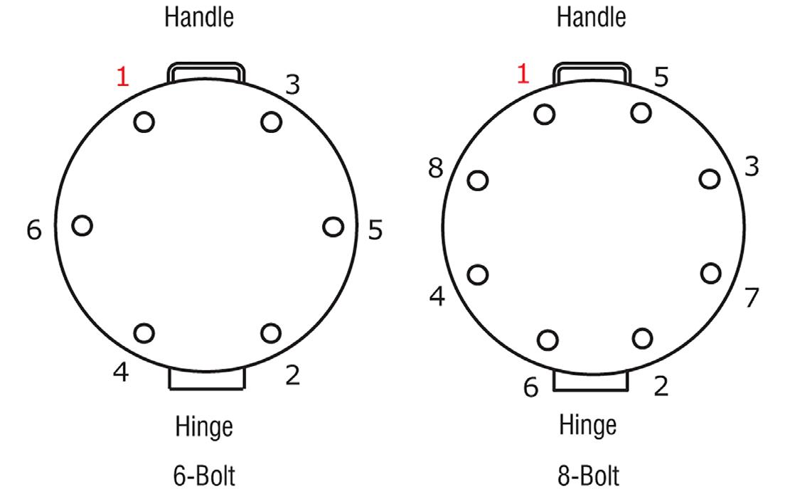
• Three star pattern tightening sequences in either a 6-bolt or 8-bolt pattern, increasing the torque in each sequence per the chart on the right.
• A rotational pass at full torque to equalize the stress on each eyebolt.
• Optional. Retorque after 4-24 hrs.
WARNING: Bolts must be tightened in the cross-pattern tightening sequence, employing the incremental rounds of tightening as prescribed in this procedure. If this is not done, the flanges may become out of parallel relative to each other, an indicator of nonuniform gasket loading and potential joint leakage.
Retorque after 4 to 24 hrs. A large percentage of the short-term bolt preload loss occurs within 24 hours after initial tightening with most occurring after 4 to 5 hours. This Round recovers this loss. Failure To Pre-Tighten The Nuts Result In Flanges That Are Not Parallel, And Could Result In Possible Leakage.
Joint Assembler:
For questions contact tech@durlon.com
Date:
Warning: These materials should never be recommended when both temperature and pressure are at the maximum listed. Properties and applications shown are typical. No application should be undertaken by anyone without independent study and evaluation for suitability. Never use more than one gasket in one flange joint, and never reuse a gasket. Improper use or gasket selection could cause property damage and/or serious personal injury. Data reported in this brochure is a compilation of field testing, field service reports and/or in-house testing. While the utmost care has gone into publishing the information contained herein, we assume no responsibility for errors. Specifications and information contained in this brochure are subject to change without notice. This edition cancels and obsoletes all previous editions.
The Seal
The purpose of a gasket is to create a static seal between two stationary flanges. The seal itself is created by achieving the proper compression on the gasket causing it to flow into the imperfections on the surface of the flange. This results in a tight, unbroken barrier, impervious to the fluid being contained.
In many instances, a good seal is obtained through the limited “swell” caused by the reaction of the inside edge of the gasket material with the fluid being contained.
A certain amount of swell is desirable, as long as it reaches an equilibrium and does not reach a condition of degradation where the gasket begins to breakdown. In many instances, the fluid being contained may “cauterize” the inside edge of the gasket and “seal off” the gasket from further fluid penetration.
Bolting
Bolted flange connections are only as good as the fastener system being used and unfortunately the fastener system is often overlooked within the system. The majority of fastener systems being used in the industrial world are threaded. The fastener system consists of at least the bolt/ stud and the nut but it is recommended to also include washers.
The application and distribution of torque can be improved through the use of washers under the head of the bolt and between the flange and nut. Washers effectively reduce the friction between the turning surfaces of the nut and bolt head to the flange, thus translating into a more accurate load being applied to the gasket. For standard applications it is recommended to use through-hardened washers, in order to prevent washer galling.
Bolting should be of sufficient strength to achieve proper compression of the gasket, to not only seal the joint, but to maintain the seal without exceeding the yield strength of the bolts being used. The torque values in our torque tables (pg. 10) are based on using ASTM A193 Grade B7 studs and 2H heavy hex nuts lubricated with never seize.
Since sheet gasket materials have micro pores, they must be sufficiently compressed to reduce porosity. Without adequate compression the system pressure can force the contained fluid into the gasket and degrade it. Therefore, when installing the gasket it is important that good technique be followed including cleaning the flanges, inspecting the flange face and the bolts and bringing the flanges together parallel and in stages. Many field problems arise from improperly installed gaskets. Refer to the Bolt Tightening Worksheet (pg. 8) for more information on installation procedures.
The Effect of Bolt Lubrication
Bolt lubrication greatly affects the torque values used when installing gaskets. To achieve the same gasket compression, a much higher torque value is required for a dry bolt versus using an effective lubricant such as molybdenum disulfide.

In a dry bolt up, or where an inefficient lubricant is used, the effort used in tightening is overcome by the frictional forces between the bolts and nuts and to a greater extent between the nuts and nut facings.
This can result in a lower gasket load and inadequate stress on the bolts, which can result in torque loss and eventual leakage in service. (see graph below)
