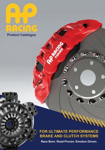
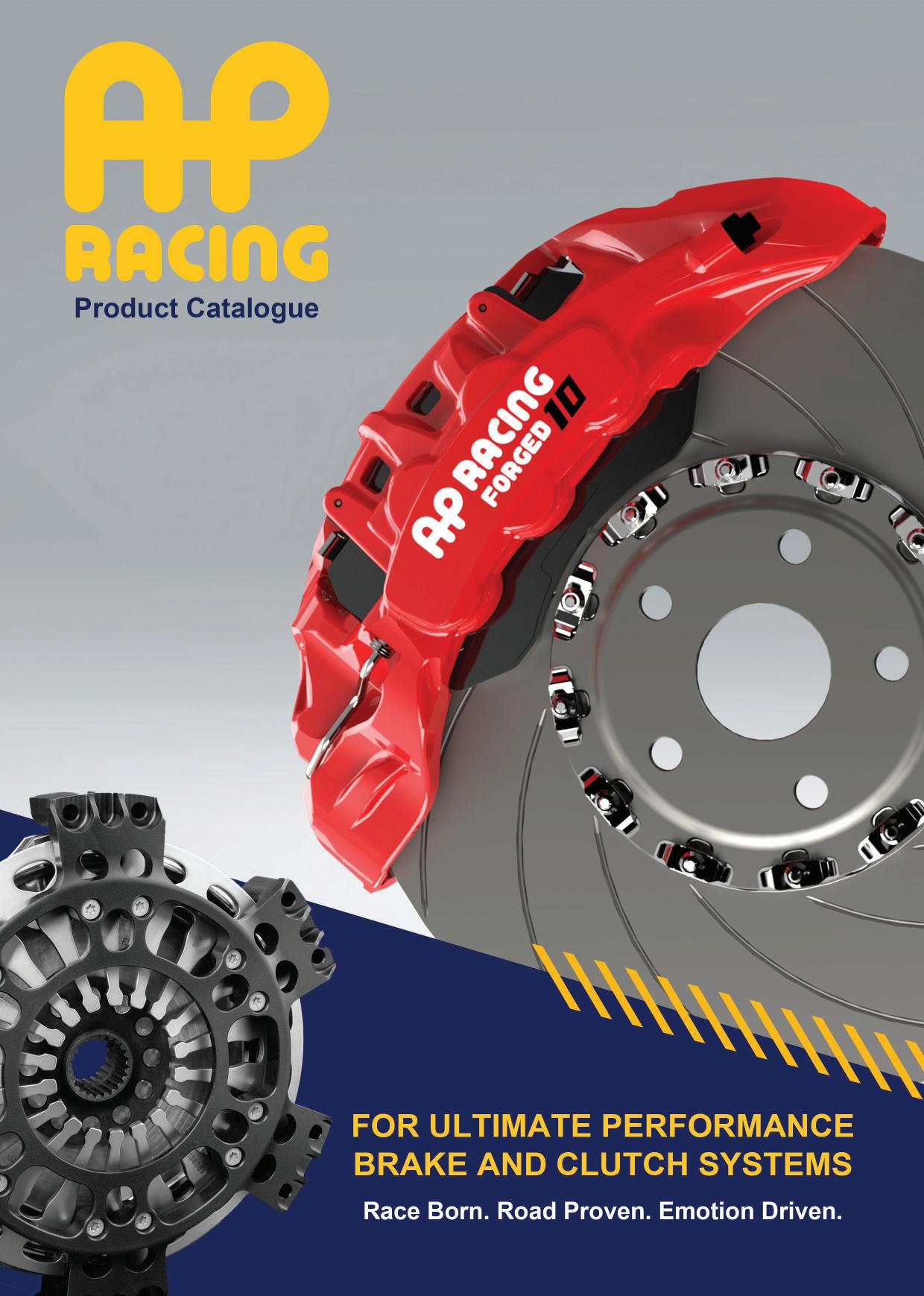
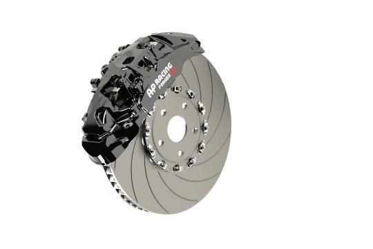
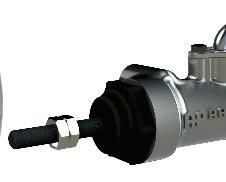
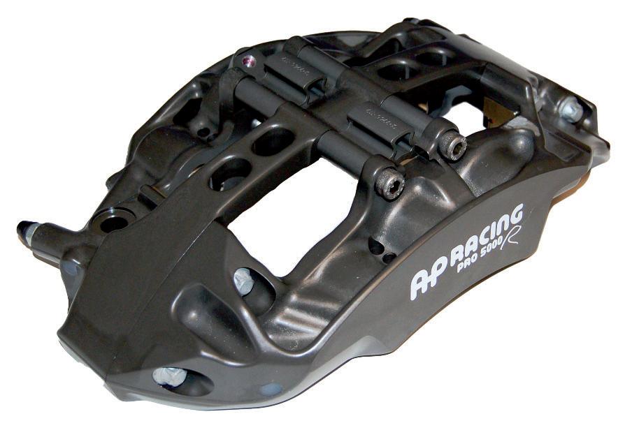
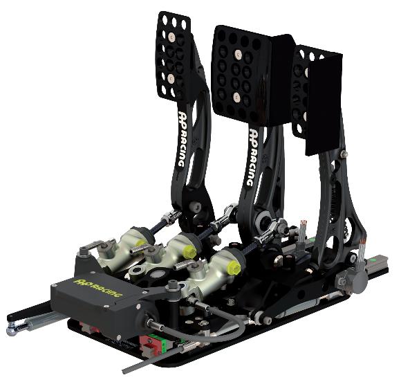
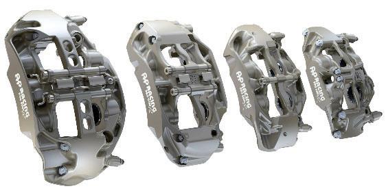
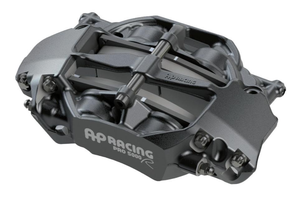
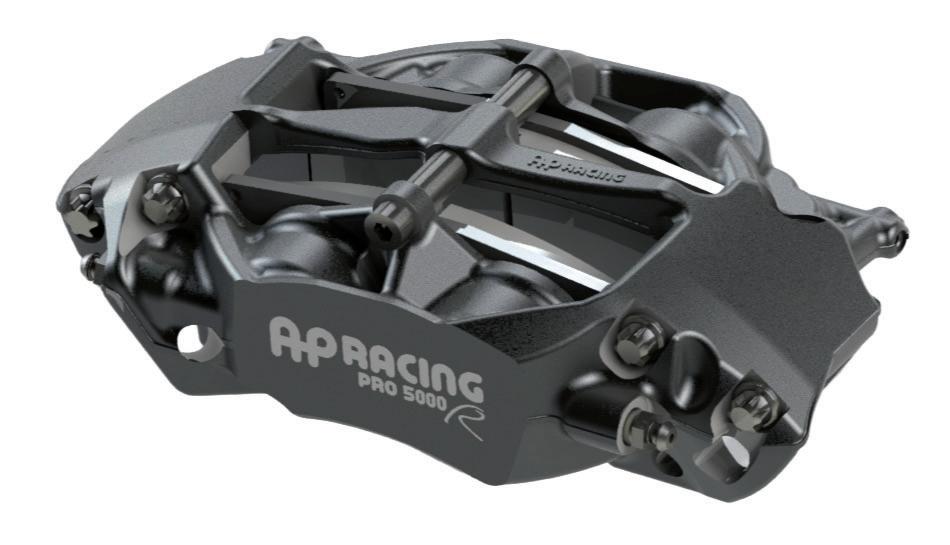
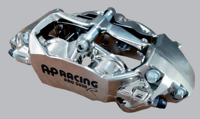
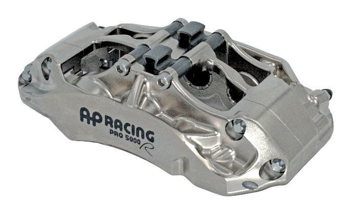
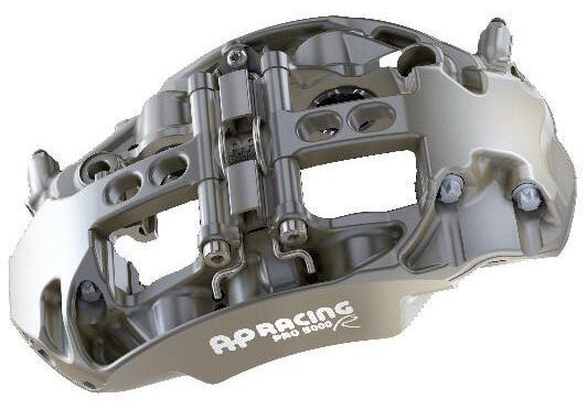
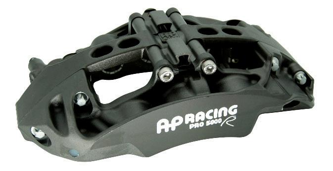
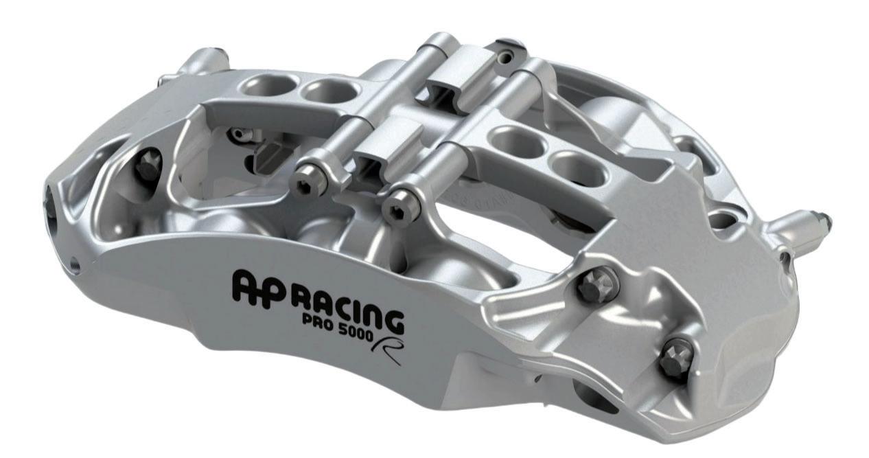
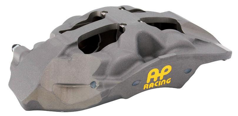
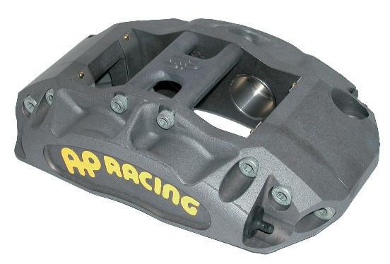
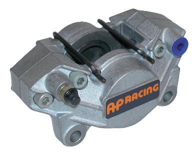
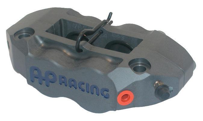
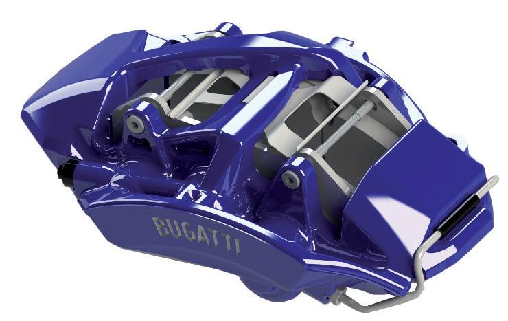
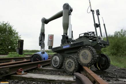
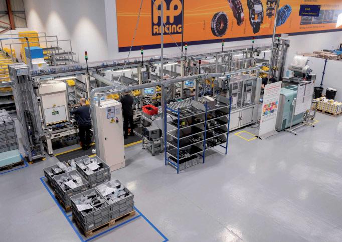
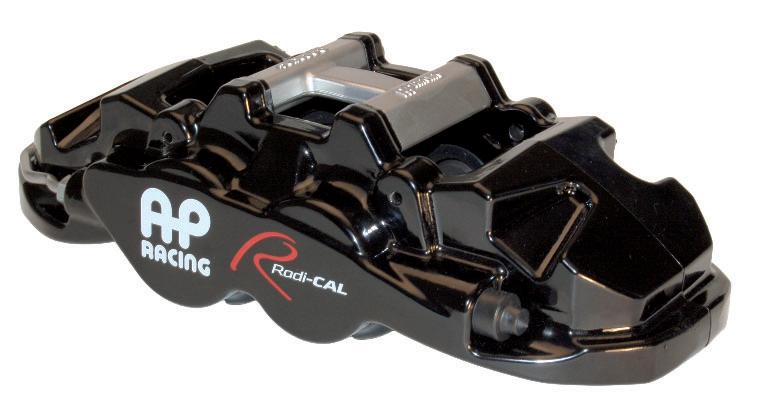
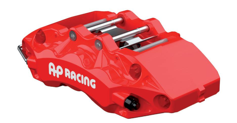
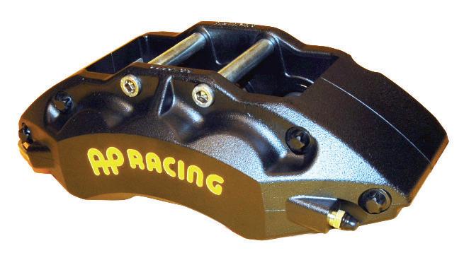
This catalogue has been designed to provide the users across all levels of Motorsport, OE / High performance and Motorcycle industry with a guide to the most popular AP Racing products. However, not all products are listed. So if your requirements differ from those in the catalogue, please contact us for assistance, we aim to be flexible.
A PDF version of this catalogue is also available for download at www.apracing.com
About us
The Company
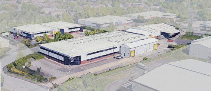
For over 55 years, AP Racing has been the leading manufacturer of performance brake and clutch systems for motorsport, OEM, aftermarket road, armoured, and motorcycle applications. Based in Coventry, AP Racing has achieved more national and international sporting success than any of its competitors.
In 2024 alone, AP Racing supplied brakes, clutches, or both to over 30 champions across the entire spectrum of motorsport.
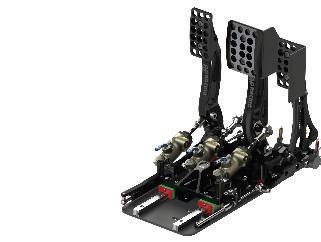
AP Racing’s core product ranges include brake calipers, clutches, discs, pads, master cylinders, pedal boxes, and air jacks, as well as road and competition brake systems for motorcycles.
AP Racing has once again achieved accreditation to ISO 9001:2015 and registration to the IATF 16949:2016 quality standards.
These certifications underline AP Racing’s commitment to providing the highest quality products and services to meet the exacting requirements of its customers.
Race
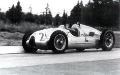
Ever since its creation, AP Racing has been at the forefront of the motorsport industry—creating winners on both the track and the road. From iron brakes to today’s carbon/carbon systems, and from large-diameter clutches to compact Ø97mm multi-plate F1 units capable of transmitting 1000 bhp at 10,000 rpm, AP Racing has continuously led the way. Our motorsport success began with the legendary Auto Unions and has continued unbroken, culminating in the 2024 championship-winning McLaren. By the end of the 2024 season, AP Racing had recorded an incredible 883 Grand Prix victories featuring either our brake calipers or clutches since 1967.
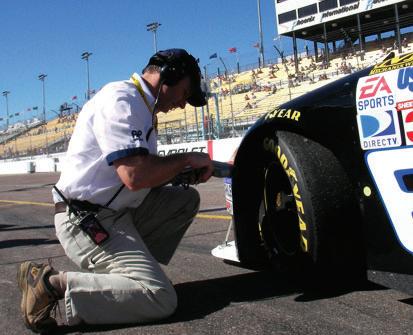
This legacy of success extends across a wide range of motorsport disciplines—including WRC, Touring Cars, NASCAR, IndyCar, GT racing, and more—cementing AP Racing’s reputation as a trusted partner in top-level motorsport worldwide.
Specialist Original Equipment
Competition is the ultimate testbed, and AP Racing’s decades of motorsport experience continue to benefit the latest OEM road cars. While the emphasis may shift to meet the everyday demands of modern road conditions, the core requirements remain the same. Supporting both low- and high-volume OEM customers, AP Racing has the resources, technology, and expertise to transfer its racing pedigree and performance to the road.
Special Projects
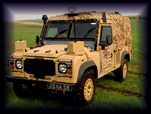
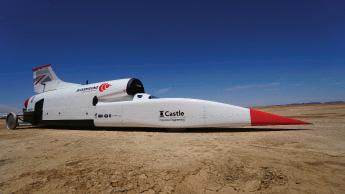
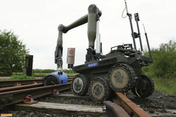
AP Racing can—and has—engineered unique solutions for various Special Vehicles sectors, including Armoured and Defence, Hybrid, Electric, Land Speed, Bomb Disposal, and even Aerospace applications, all tailored to each customer’s specific criteria and requirements.
With a range of brake and clutch systems designed for varying duty levels, solutions can be developed using our specialised vehicle testing procedures that replicate the environments and scenarios these vehicles encounter.
With decades of experience and a wealth of talent across all areas of the business, AP Racing is ideally positioned to deliver the innovation required in these demanding and dynamic market sectors.
Engineering & Technology
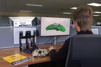
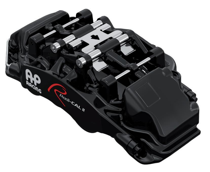
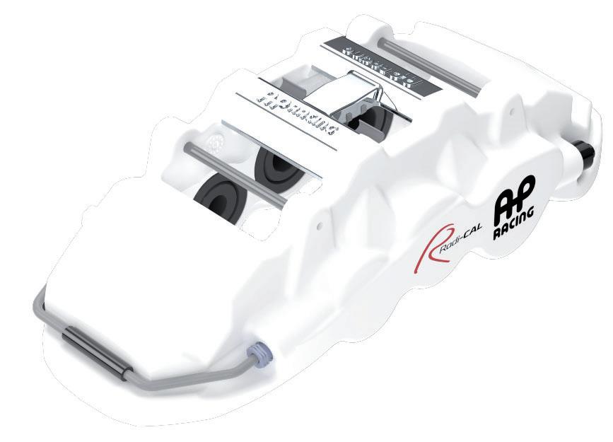
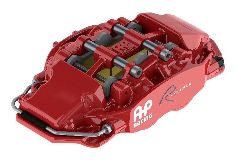
Staying at the pinnacle of motorsport and performance road brake and clutch design for over 55 years is no easy feat. However, AP Racing’s extensive resources ensure the very best is always available to its customers. From state-of-the-art 3D solid modelling and FEA CAD facilities to advanced research, development, testing, and quality departments, AP Racing continuously pushes the boundaries of technology. Around 18 years ago, AP Racing introduced its first Radi-CAL™ brake caliper—a revolutionary advancement in caliper design. This innovative concept improved efficiency, cooling, and driver control, setting new standards in motorsport braking technology.
Today, Radi-CAL™ technology is used across all major racing series worldwide, including Formula 1, GT, Touring Car, WRC, and NASCAR. AP Racing continues to develop and expand the Radi-CAL™ range, applying this race-proven technology to additional motorsport applications, as well as to OEM road and aftermarket calipers.
To date, AP Racing has produced over 190 first and second-generation Radi-CAL™ variants and continues to refine the design process strengthening its position as a world leader in high-performance brake caliper technology.
The Complete Competitive Range
This product catalogue presents an unrivalled selection of brake and clutch systems and accessories. It features an integrated range of thousands of carefully developed and selected components, designed to meet the needs of motorsport, OEM, high-performance upgrade, and motorcycle applications.
With a global network of specialist distributors, modern online communication tools, and express delivery services, AP Racing ensures its extensive range of high-performance products is readily available wherever you are.
IMPORTANT NOTE: While this catalogue provides comprehensive details of AP Racing products, our website (www.apracing.com) offers the most up-to-date information on any changes or updates to our product range.
For many years, AP Racing has supplied some of the world’s leading high-performance vehicle marques with bespoke brake and clutch systems. Through a proven design and development programme—combined with dedicated engineering support—AP Racing delivers high-performance, reliable brake and clutch solutions tailored to a wide range of performance vehicles. ce, nce
IMPORTANT INFORMATION
Whilst this catalogue provides a comprehensive overview of some of AP Racing’s most popular products, our website (www.apracing.com) contains the full product range and offers the most up-to-date information, including any changes or updates to our product lines.
Note: A version of this product catalogue including installation drawings in PDF format for the products featured in this publication, where available can be downloaded by scanning the QR code opposite.
Disclaimer: All information contained in this catalogue is intended as a guide only. It is the responsibility of the reader to verify its accuracy. All images are for illustrative purposes only. All images and content are the copyright of AP Racing and may not be reproduced in any form without prior written consent.
Contents - Page
Introduction - inside front cover
Table of contents - 1
New products - 2 to 3
Brake Calipers - 4 to 41
General information - 4
Pro Sport - 7
Pro 5000 ) - 8
Formula cars - 8
Hypercar / GT & Endurance - 12
Rally - 13
Touring car - 15
2 Piston- 16
Historic - 17
Motorcycle - 19
Performance upgrade road car - 21 to 30
10 Piston - 21
Radi-CAL™ - 21 to 24
Forged Steel - 25
Technical information - 31
Caliper spare parts - 34
Brake Discs 42 to 54
General information - 43
Ventilated- 44
Ventilated disc & bell kits - 47
Solid- 48
Integral ventilated - 47
Integral solid - 48
Technical information - 49
Carbon disc information - 53
Brake Pads - 55 to 64
General information - 56
AP Racing APF brake pads - 57
Brake pad profiles - 59
Contents - Page
Brake Kits - 65 to 67
Application kits - 66
Actuation - 69 to 92
Master cylinders - 70
Motorcycle cylinders - 79
Reservoirs - 81
Pedal boxes - 83
Balance bars - 86
Balance bar adjusters - 87
Hand brakes - 88
Proportioning valves - 89
Brake fluid - 90
Dry bleed system - 91
Hydraulic fittings - 92
Carbon/Carbon Clutches - 94 to 102
General information - 94
Ø115mm Clutches - 95
Ø138mm Clutches - 96
Ø140mm Clutches - 96
Ø184mm Clutches - 98
Ø200mm Clutches - 98
Technical information - 99
Metallic Race Clutches - 103 to 123
General information - 103
Ø115mm Clutches - 105
Ø140mm Clutches - 107
Ø184mm Clutches - 110
Ø200mm Clutches - 118
Ø215mm Clutches - 120
Technical information - 121
Clutch Slave Cylinders - 124
Clutch Release Bearings - 126
Clutch Mounting Studs - 127
Air Jacks - 128 to 131
General information - 129
CP3985 Air jacks - 129
CP3945 Air jacks - 129
Air jack accessories - 130
Air jack maintenance - 131
Distributor contact details - 132
Clothing Merchandise - Inside back cover
NEW PRODUCTS
AP Racing has many new exciting products and projects to be released throughout the next couple of years and will be announcing all relevant details through our website and social media platforms.
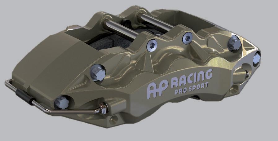
PRO SPORT Caliper range - Race
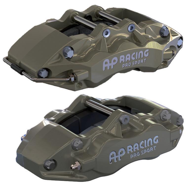
Both calipers offer a cost effective forged brake system for R2, R4 and other cost conscious motorsport series.
The evolution of our forged technology has resulted in the CP9230, 4 Pot and CP9280, 6 Pot Series which are high quality off the shelf modern brake calipers. These two piece aluminium radial mount designs, are internally ported (4 Piston only) with stainless steel piston, anodised surface treatment, optional bleed screw shield fitment for added protection. See page 7 for details.
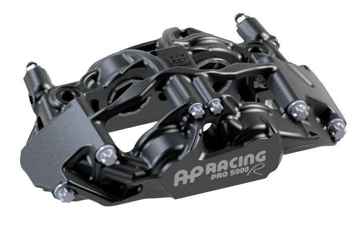
195mm Mounting centred PRO 5000 ) calipersRace
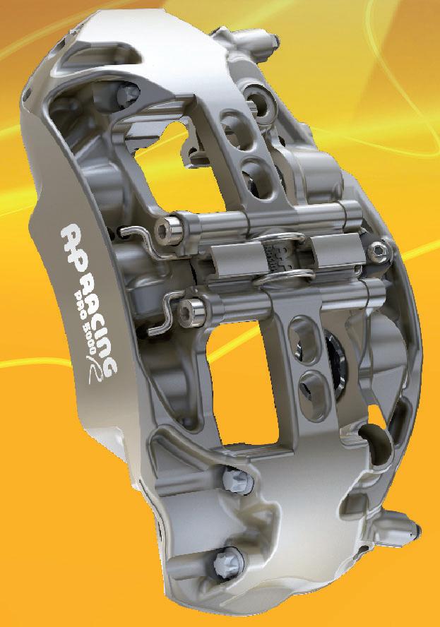
CP9667 is new 6 piston front caliper being added to our highly successful Pro 5000 ) range. Being virtually identical to CP9668 but has 195mm centres, this caliper offer directly fitment to McLaren and Lotus GT race applications. See page 10 for details.
Brake Bias Adjuster - Race
CP9395 Brake Bias Adjuster (BBA) is a simple, compact, and cost effective actuator that controls the position of a balance bar, based on a CAN target.The device requires a 12Vdc power supply and interface is solely via CAN.The BBA’s low profile and a compact footprint allows for easy integration and low false floors to maximise space in the footwell. The device can be supplied pre-installed to an AP Racing pedalbox, with factory set calibration. See page 87 for details.
Performance upgrade brake calipers
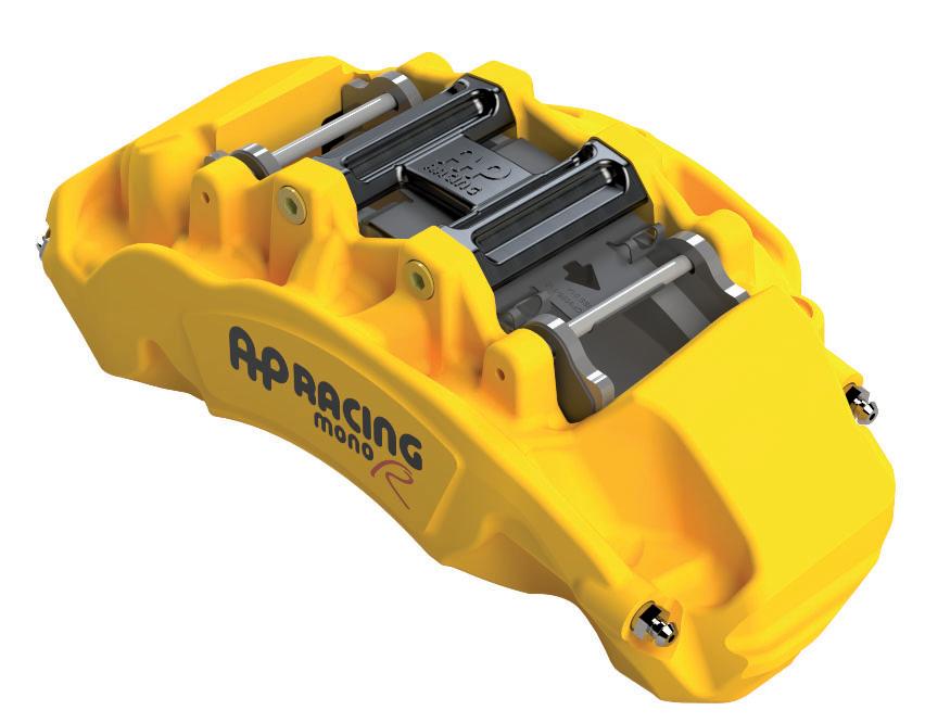
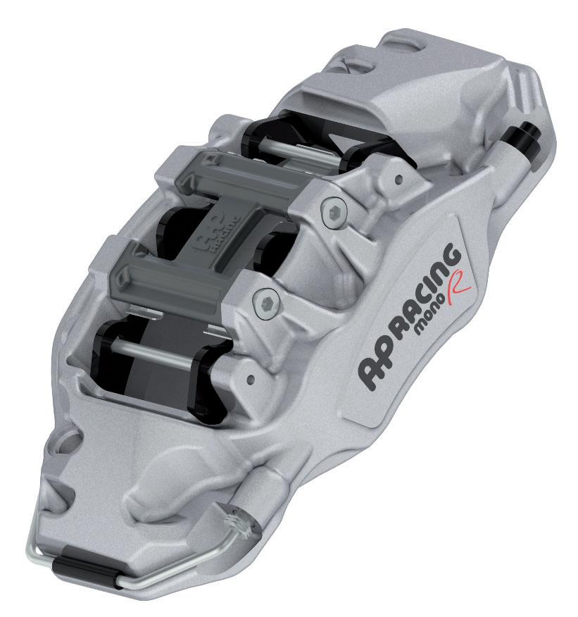
The latest calipers to join our performance upgrade family are the 4 and 6 Piston Radi-CAL™ range, 6 Piston Forged Steel, and Forged 10 and Mono our first upgrade 10 piston calipers, all are evolutions of our unrivalled forging expertise and patented Radi-CAL™ technology for performance road cars requiring a brake upgrade. See Below and opposite for details.
Heavy duty forged steel brake caliper - Road
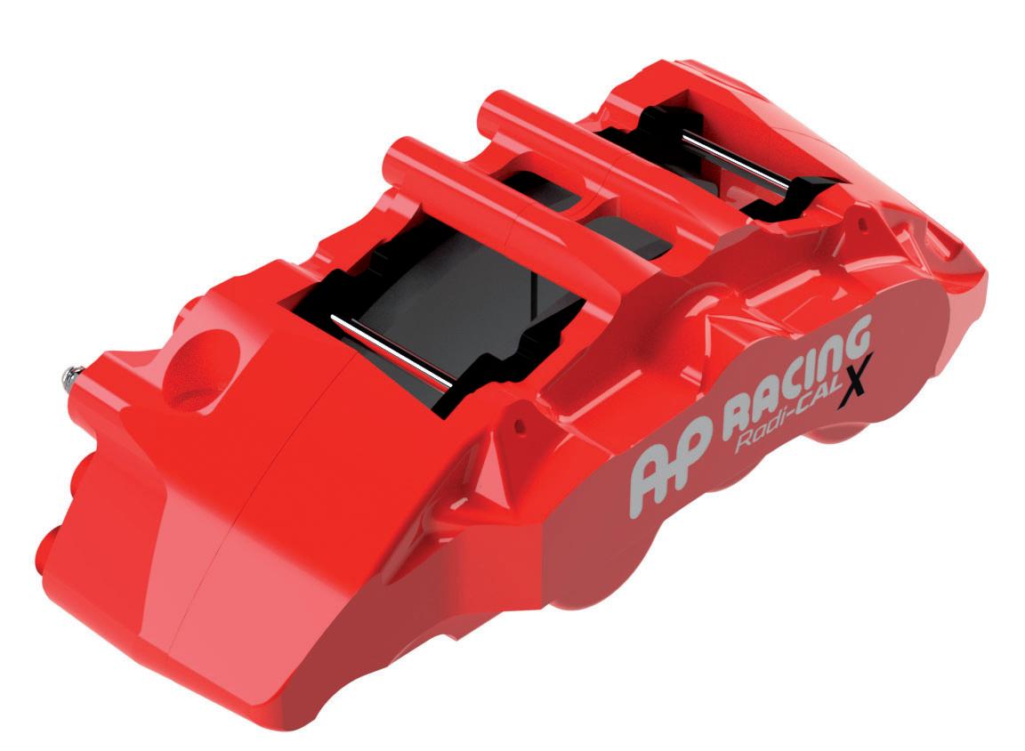
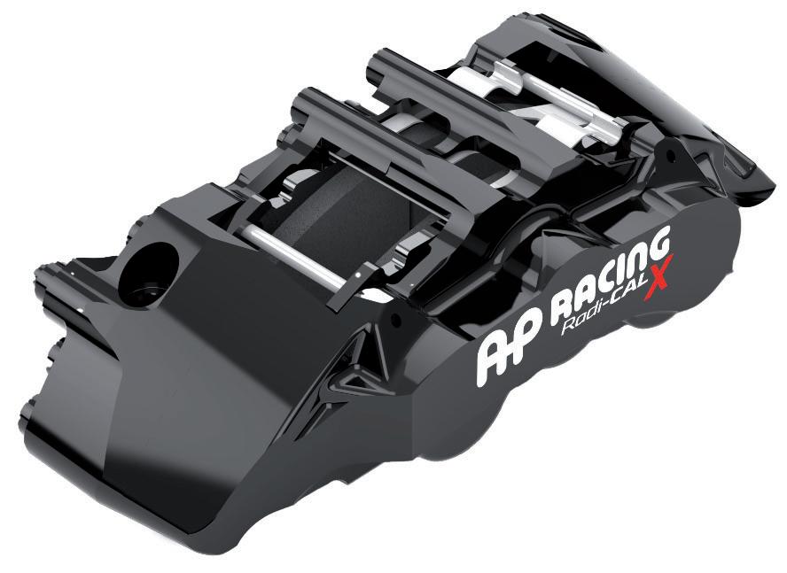
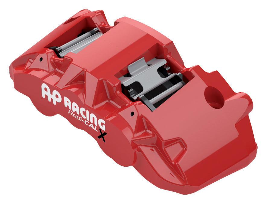
AP Racing Radi-CAL™ X calipers are designed to provide a cost-effective and high-performance braking solution for SUVs, Armoured and Military and similar vehicle platforms. Crafted using AP Racing’s advanced forging techniques, this steel caliper combines high-quality construction, high performance and long term durability with visually striking aesthetics. They deliver superior braking performance, specifically tailored for the demands of the SUV, Armoured and Military markets ensuring excellent braking power and safety. The range offers two options:
- Heavy Duty - CP8576 & Super Duty - CP8575 are unique forged 6 piston calipers, and has been specifically designed for AP Racing to supply the SUV markets. Available in an advanced gloss Black, Red or Silver paint finish, the new calipers provide a braking solution to GVW of over 4 tonnes for heavy duty and 5 tonnes for super duty. See page 25 for details.
5 tonnes for super Se
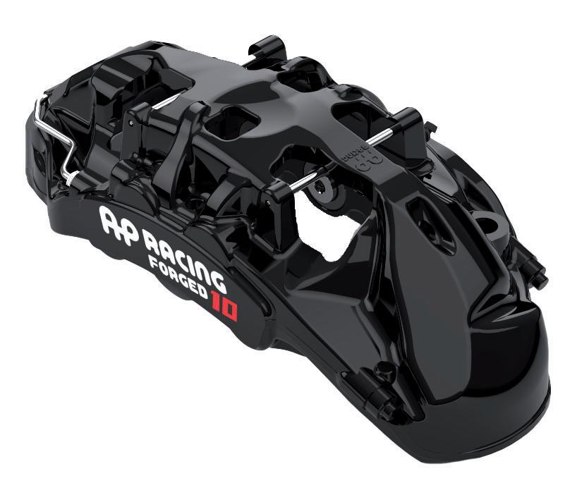
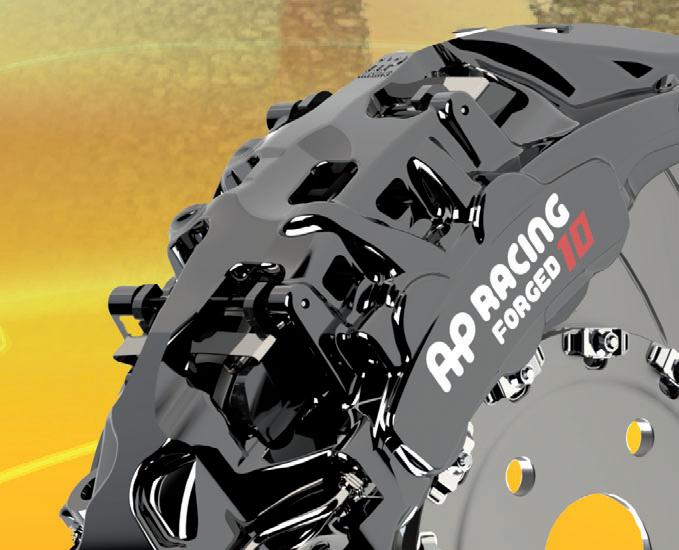
FORGED 10 - 10 Piston
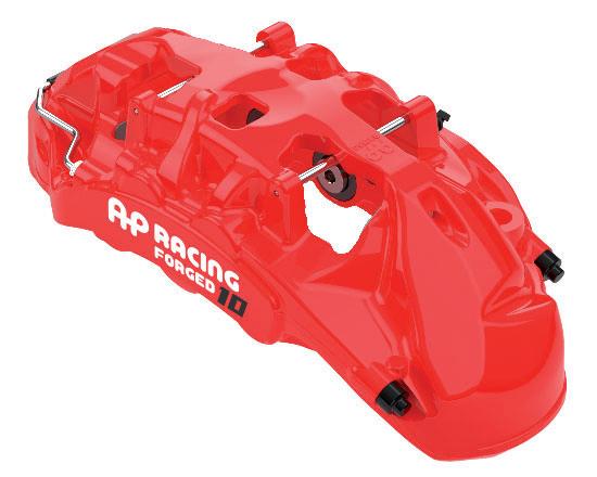
CP7410 is a 10 piston monobloc caliper that’s based on our highly successful OEM variant, meaning we can evolve this design to provide our upgrade customer the option when utilising Ø420mm x 40mm iron discs. Unlike the multiple paint finishes other caliper within the upgrade family, Forged 10 will only be available in black, red or white colours and will also be supplied with brake pads fitted See page 21 fordetails.
NEW PRODUCTS
Radi-CAL™ - Electric vehicle range
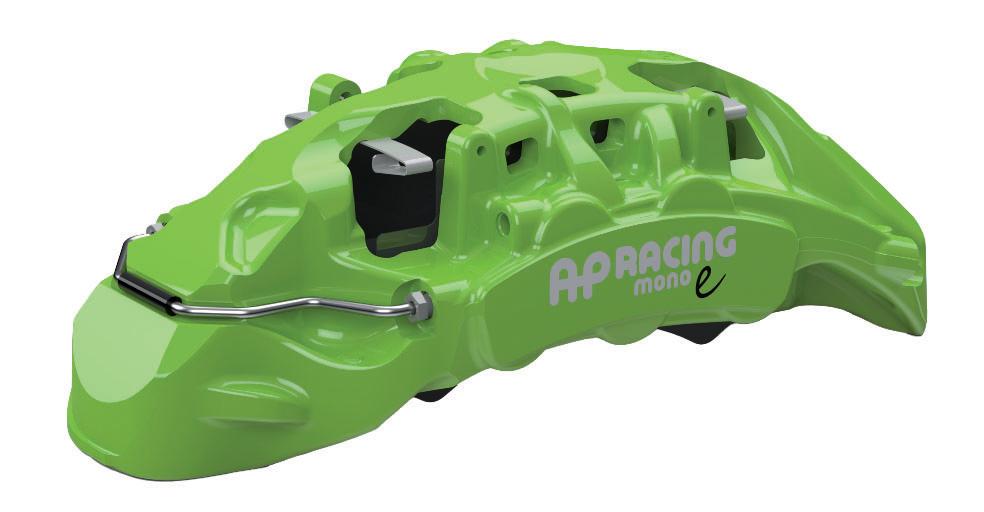
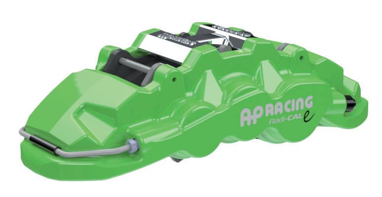
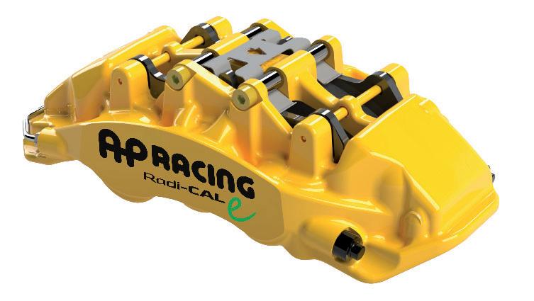
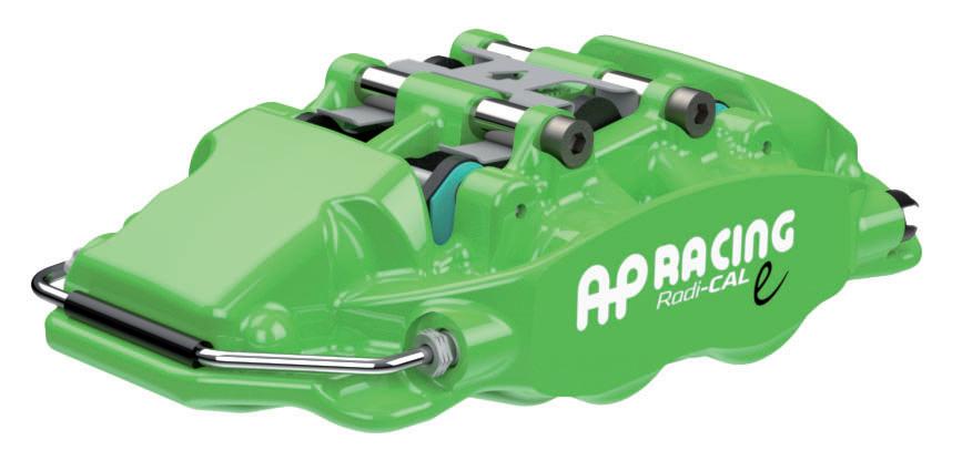
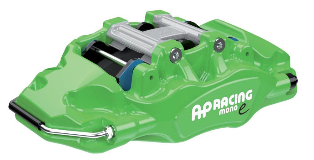
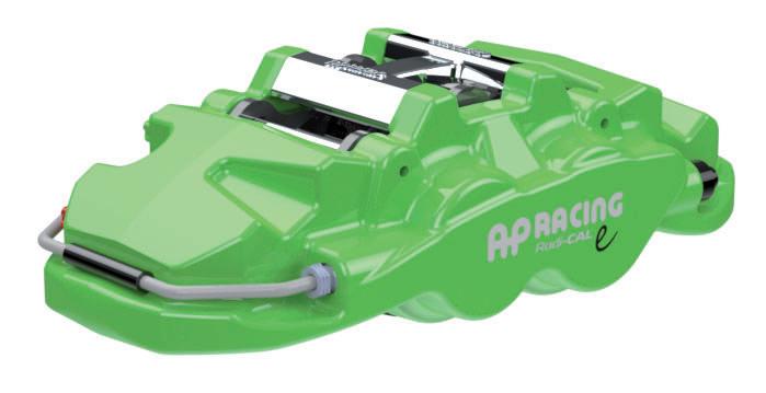
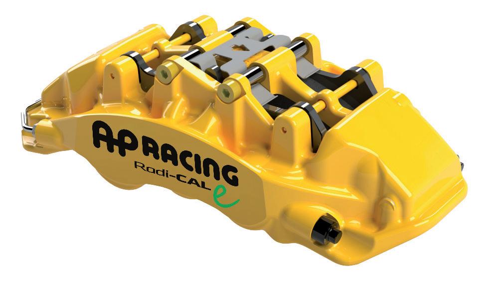
This new range has been specifically designed for the electric vehicle user that wants to maintain, or improve, their current low drag efficiency with the added benefit of upgrading the braking performance of their car. Whilst the family shares technology from other upgraded families, Radi-CAL™e stands alone with unique seal technology, branding and attractive advanced gloss black, green, red, silver, yellow or white anti-corrosion paint, plus brake pads supplied and fitted.
Below are details of each caliper within the Radi-CAL™ family.
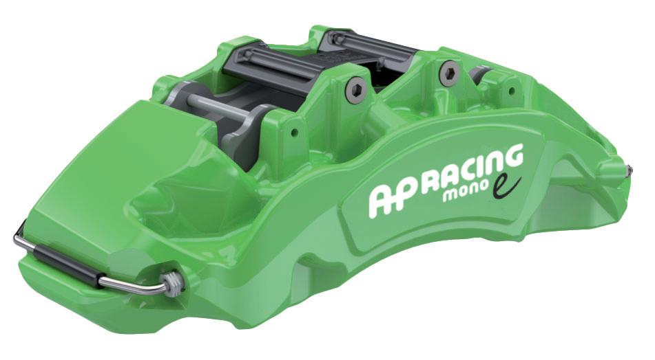
MONO - 10 Piston
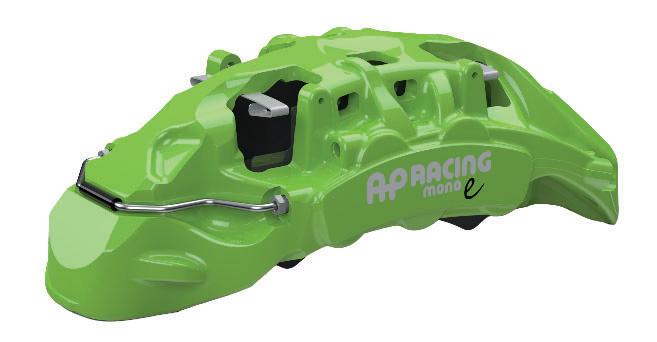
CP7411 is a 10 piston forged monobloc caliper that’s based on our highly successful OEM variant and designed to accept Ø420mm x 40mm iron discs. CP7411 will be available in our advanced gloss black, green, red and white anti corrosion paint finishes, along with pad anti-rattle clips and low drag brake pad shim technology applied. See page 21 for details.
MONO - Generation 2 - 6 Piston
CP9370 / CP9371 & CP9372 are 6 piston forged monobloc calipers, based on our highly successful Mono R variants and designed to accept Ø410mm max / Ø370mm min x 36 or 35mm thick cast iron discs. See page 21 for details.
WR2 Radi-CAL™ - 6 Piston
CP9360 / CP9361 & CP9362 are 6 piston forged two piece calipers, based on our highly successful World Radi-CAL™ 2 variants and designed to accept Ø390 x 36mm thick cast iron discs. See page 22 for details
WR1 Radi-CAL™ - 6 Piston
CP9320 / CP9321 & CP9322 are 6 piston forged two piece calipers, based on our highly successful World Radi-CAL™ 1 variants and designed to accept Ø410mm max / Ø380mm min x 36mm thick cast iron discs. See page 23 for details.
MONO - Generation 2 - 4 Piston
CP9380 / CP9381 & CP9382 are 4 piston forged monobloc calipers, based on our highly successful Mono R variants and designed to accept Ø380mm x 32 or 28mm thick cast iron discs. See page 23 for details.
WR2 Radi-CAL™ - 4 Piston
CP9340 / CP9341 & CP9342 are 6 piston forged two piece calipers, based on our highly successful World Radi-CAL™ 2 variants and designed to accept Ø380 x 32 or 28mm thick cast iron discs. See page 24 for detail.
WR1 Radi-CAL™ - 4 Piston
CP9330 / CP9331 & CP9332 are piston forged two piece calipers, based on our highly successful World Radi-CAL™ 1 variants and designed to accept Ø390 x 32 or 28mm thick cast iron discs. See page 24 for details.
BRAKE CALIPERS
GENERAL INFORMATION
RACE CALIPER RANGE
PERFORMANCE UPGRADE CALIPER RANGE
TECHNICAL INFORMATION
CALIPER SPARE PARTS LISTS
GENERAL NOTE:
Brake calipers are SAFETY CRITICAL ITEMS and AP Racing designs for three distinct market sectors, Race (Competition), OEM and Performance upgrade road / Trackdays.
IMPORTANT NOTE: AP Racing’s range of race caliper are unsuitable for use on the public highway. AP Racing recommends contacting our technical department or an officially listed distributor/dealer for caliper selection help and/or advice. AP Racing recommends taking the following information into consideration before making your caliper selection:
- NEVER ATTEMPT ANY FORM OF MODIFICATION TO AN AP RACING BRAKE CALIPER. Any modifications may compromise your safety
- Purchasers accept and recognise that due to the nature of the motorsport environment racing brake equipment may be subjected to extreme conditions beyond the expectation or control of seller and which could exceed the design limits of this product. The Seller makes no representation or warranty that this equipment can be safely installed on any specific vehicle or is suitable for use under any specific racing conditions.
- Responsibility for ensuring that any AP Racing brake equipment is suitable for the vehicle rests with the installer. It is the user’s responsibility to ensure that safe operating conditions are not exceeded.
- Brake calipers must be regularly maintained / reconditioned. Replacement seals should be fitted using the appropriate seal kit available from AP Racing. Under adverse conditions, reconditioning should be more frequent. If peak caliper temperature exceeds 240°C or temperatures of over 180°C are exceeded for a cumulative period of 1 hour then caliper seals must be replaced
- Brake caliper temperatures must be continuously monitored under racing conditions and controlled by adjusting the flow of cooling air to avoid peak temperatures above 240°C, maximum continuous temperatures above 200°C and excessive temperature fluctuation.
- For maximum safety caliper temperatures should be as low as possible. Heat insulating pistons made from special stainless steel or titanium are also available to reduce heat transfer to the caliper and brake fluid
- AP Racing offer a full factory reconditioning service for AP Racing brake calipers
- If you have any doubts about the installations, operations or maintenance of AP Racing brake calipers call or e-mail the following addresses: racetech@apracing.co.uk / roadtech@apracing.co.uk or telephone our technical support on +44 (0)247663 9595 .uk / roadtech@apracing co uk or telephone our technic
BRAKE CALIPERS
General Information
INTRODUCTION
For over 55 years AP Racing has been a world leader in the technology and manufacture of motorsport and high performance brake calipers. During this period, hundreds if not thousands of the world’s premier races and championships have been won using AP Racing braking systems.
With one of the most comprehensive ranges available, AP Racing can offer a brake caliper suitable for every category of motorsport, supplemented with a wide range of brake calipers to suit high performance road car applications for both OE and upgrade conversion kits.
The caliper range has been separated into the following groups to aid selection: Race, Historic, Motorcycle and Performance upgrade road.
The calipers shown from pages 6 to 30 are the most popular calipers selected from our extensive range, and will provide the solution to most, if not all, applications. These standardised calipers benefit from a more competitive price structure coupled with preferential delivery times. Specialist caliper ranges such as those used in Formula One and OEM Specific are not shown in this catalogue. The complete range however includes many other options and the majority can be found on www.apracing.com, so if you require a caliper not illustrated please contact AP Racing for information on availability, price and delivery.
eand willprovide thesolution to most if notall
DESIGN & DEVELOPMENT EXCELLENCE
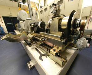
All design and development activities are conducted at AP Racing’s headquarters in Coventry, UK. Equipped with three advanced brake dynamometers, our facility enables us to replicate the most demanding test conditions, ensuring superior performance and reliability. Our design team utilises the latest technologies to engineer some of the most aesthetically refined and high-performing brake calipers available while maintaining cost-effectiveness to meet the diverse demands of global markets.
Radi-CAL™: A Revolutionary Approach to Caliper Design
First introduced in 2007, AP Racing’s patented Radi-CAL™ design philosophy marked a transformative shift in brake caliper engineering. Departing from conventional design principles, Radi-CAL™ introduced a completely new approach focusing on lightweight construction, increased stiffness, improved thermal efficiency, and enhanced aesthetics.
The first Radi-CAL™ design was for an F3 car and compared to its conventional predecessor, offered a 29% reduction in brake fluid displacement under hydraulic pressure a 33% reduction in displacement when torque loaded and achieved even distribution of stress loads throughout the caliper body. This new design philosophy was applied to numerous race formulae, including those with highly restricted space envelopes. Its primary focus was efficiency – reducing caliper brake fluid consumption. This allowed for smaller master cylinders, thereby improving driver brake modulations and maximum caliper pressure and torque. The caliper’s organic shape also significantly increased surface area, leading to improved cooling performance. To date, more than 200 Radi-CAL™ variants have been developed, spanning a wide range of motorsport,OEM, and high-performance aftermarket applications.
What is Radi-CAL™ ?:
Radi-CAL™ is a term used to describe AP Racing’s patented asymmetrical brake caliper design, which incorporates advanced Computer-Aided Design (CAD) and Finite Element Analysis (FEA) to achieve a revolutionary approach. The technology allows for the creation of organic, unconventional designs that depart significantly from traditional caliper architectures. The Radi-CAL™ design philosophy has enabled AP Racing to continually explore new design possibilities, focusing on making not only brake calipers but also clutches lighter, stiffer, and more efficient in terms of heat dissipation. This has resulted in a design that is not only more functional but also more aesthetically pleasing. Radi-CAL™ exemplifies the power of horizontal innovation, transitioning motorsport-focused technologies into broader automotive applications. By rethinking the fundamental principles of caliper design, Radi-CAL™ achieves significant improvements through nonsymmetrical and organic shapes. The design optimises the distribution of material, enhancing caliper stiffness while reducing weight. The careful control of caliper deflection under torque and the even distribution of stress loads throughout the caliper body lead to improved hydraulic fluid displacement, resulting in better pedal feel, improved modulation, and superior control.
The key benefits of the Radi-CAL™ design are:
Asymmetrical Design: The non-symmetrical, forged aluminum caliper body redistributes material based on dynamic loads, resulting in a caliper that is both lighter and stiffer than conventional designs.
Weight Reduction: By removing unnecessary material and utilizing voids in strategic locations, Radi-CAL™ calipers achieve significant weight savings without compromising strength and improves vehicle handling and responsiveness.
Enhanced Stiffness: The design increases both static and dynamic stiffness which leads to improved pedal feel, modulation, and reduced deflection under load.
Optimized Airflow: The caliper’s design facilitates better airflow, aiding in heat dissipation and maintaining consistent braking performance.
Compact Footprint: The asymmetric profile and internal fluid porting allow for efficient packaging, enabling fitment in tighter spaces.
Even Pad Wear: The design promotes uniform pressure distribution, leading to consistent pad wear.
Extended Service Life: The robust construction and efficient heat management contribute to longer caliper and component lifespan.
FORGED
AP Racing released its first forged caliper in 2012, and it’s widely considered that AP Racing is known as the world leading specialist in applying near-net shape forging for high-performance brake calipers, leveraging its experience and expertise over the years to produce lightweight, strong, and highly durable components optimised for demanding motorsport and automotive applications. Near-net shape forging is a precise manufacturing process that forms metal parts very close to their final shape, significantly reducing machining and material waste. It improves material efficiency by cutting raw material use by up to 50% and enhances strength by aligning the metal’s grain structure for greater durability and fatigue resistance. Taking this forging approach has led AP Racing to manufacture all its brake calipers with combine precision, strength, and efficiency, making them ideal for high-stress environments where performance and reliability are critical.
Near-net forged construction, provides the following key benefits:
• Allows greater material movement for a true Radi-CAL™ design
•Ability to create complex forms & reduced sections whilst maintaining material integrity – enabling more efficient geometry.
• Optimised grain flow improving strength and fatigue performance.
•Excellent surface finish & controlled parting lines which aids painted caliper appearance with zero porosity and inclusions.
l for
Old F3 Caliper
F3 Caliper OldF3Caliper
Radi-CAL
BRAKE CALIPERS General Information
ROAD OR RACE?
It is important to choose the correct type of brake caliper for the intended application. The design requirements for a brake caliper to be used on the public highway (Road) or for competition use are significantly different.
A road caliper often has to go for long periods without servicing or maintenance therefore corrosion protection and durability are primary considerations. A brake caliper designed for competition use, must be lightweight yet capable of operating reliably at high temperatures, however it is normally cleaned and serviced very frequently. AP Racing produce brake calipers optimised for these three very different applications. Although generally derived from our racing calipers, all AP Racing OEM & Performance road calipers have a protective paint finish, wiper (dirt) seals or boot seals to prevent dirt ingress and are of a heavier construction than calipers intended solely for competition use. AP Racing strongly recommends that only purpose designed ‘road’ calipers are used on vehicles intended for regular use on the public highways. Specified race calipers are for that use ONLY.
STANDARD CALIPER FEATURES
◘ Differential bores and/or piston positioning are used on all multi-piston calipers to combat pad taper.
◘ High temperature seals are standard on all race (competition) calipers.
◘ Hard anodised surface treatment is standard on all competition calipers for optimum durability. (Except iron calipers and where indicated).
◘ Road calipers have a high performance paint finish applied on top of the hard anodising for maximum durability and protection against road salts and other debris.
◘ Radial mount fixings are standard unless indicated otherwise.
◘ All road calipers have piston dirt seals to protect against ingress of harmful debris.
◘ Where fitted, all bridge pipes on calipers are Stainless Steel.
◘ Most AP Racing calipers are fitted with replaceable Steel wear plates to protect pad and caliper body.
CALIPER, SEALS & TEMPERATURE
Because race brake calipers are sometimes subjected to very high and unpredictable operating temperatures, they must be examined and seals must be replaced on a regular basis to maintain efficiency and safety.
Seal life is governed by time at temperature which should therefore be kept as low as possible by provision of cooling airflow.
For guidance only, AP Racing offer the following recommendations :(temperatures measured on outside of caliper adjacent to logo):
◘ Calipers that regularly run at up to 180°C – Re-seal every other event.
◘ Calipers that run intermittently from 180°C to 220°C and above – Re-seal as soon as possible.
◘ Reduce “soak” temperatures after the car has come to rest where possible (e.g. Do not leave foot on brake pedal when stationary with hot brakes) as this can cause excessive caliper temperatures.
CALIPER HANDING
- Calipers are available to suit installation in front (Leading) or behind (Trailing) the axle.
- The following abbreviations are used in this publication:-
◘ RHT = Right Hand Trailing.
◘ LHT = Left Hand Trailing.
◘ RHL = Right Hand Leading.
◘ LHL = Left Hand Leading.
- Bleed screws must always be positioned at the top.
- Discs must always pass the small piston first on differential bore calipers.
- Cross over pipes must always be positioned at the bottom.
PART NUMBERING SYSTEM
An explanation of a most common brake caliper part number in this catalogue;
CP6278- 2S7MPD
NoExplanationDescriptionAlternative Part Numbers
1Caliper family numberBase caliper number
2Stroke number Even Number = Right hand caliper / Odd Number = Left hand caliper
3Position of inlet adaptor S = Sidefeed / E = Endfeed
4Anti-knockback spring 0 = No spring / 4 = 4lbs. / 7 = 7lbs / 9 = 9lbs.
5Piston material No character = Aluminium Alloy / L = Stainless Steel / M = Titanium
6 & 7Options C = Pistons fitted with caps / P = Pistons can accept caps D = Cooling duct supplied
SERVICING AND RECONDITIONING
Some new calipers have an alternative part numbering system, e.g. CP7410-2ABG20 - “CP7410” = Family number. - “-2” = Stroke number. - “A” Denotes piston material. - “BG20” Denotes paint colour.
◘ Regular examination and maintenance of brake calipers is essential to maintain safety and efficiency of operation.
◘ AP Racing recommend that brake calipers should be cleaned with soapy water only, as this will not damage any of the seals or painted surfaces.
◘ Replacement seals should be soaked in brake fluid for a minimum of 30 minutes prior to fitment.
◘ AP Racing will no longer supply replacement fluid pipes for road calipers. These must be RETURNED to AP Racing for replacing.
◘ A complete reconditioning service is available.
◘ Seal repair kits and other spare parts e.g. Pistons, bleed screws etc, for calipers detailed, and older obsolete calipers are available, and can be identified by referring to pages 34 to 41.
◘ For more information please contact AP Racing technical support.
DRY BLEED SYSTEMS (DRY BREAKS)
A Dry Bleed System has been designed for use with any AP Racing calipers suitable for ‘O’ Ring sealed bleed screws. The male dry bleed valve is fitted in place of the bleed screw, once fitted there should be no need to loosen or remove the coupling unless it is being replaced. For detailed information please refer to page 91.
RACE BRAKE CALIPERS
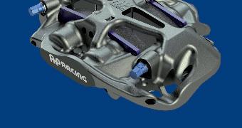
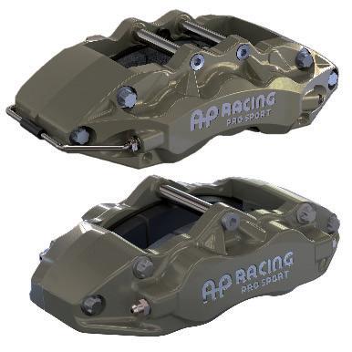
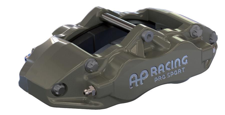
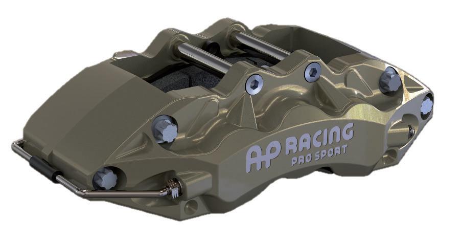
PRO SPORT is our new lowest range of entry level forged brake calipers. This range of calipers offer a cost effective brake system for R2, R4 and other cost conscious motorsport series. The evolution of our forged technology has resulted in the CP9230, 4 Pot and CP9280, 6 Pot Series which are high quality off the shelf modern brake calipers. These two piece aluminium radial mount designs, are internally ported (4 Piston only) with stainless steel piston, anodised surface treatment, optional bleed screw shield fitment for added protection. This page provides the basic installation dimensions for both the calipers and the discs, full customer drawing are available on www.apracing.com.
4 Piston front and / or rear - Suits Ø355 max / Ø310mm min x 32mm discs
- Forged, two piece aluminium alloy body. - Radial mount, 152.0mm x 44.0mm centres.
R4 &
- Suits Ø355.0mm or 310.0mm x 32mm thick disc.
- Stainless Steel pistons. - High temperature seals. - 4lb Anti-knockback springs fitted.
- Stainless Steel wear plates.
LHT
R2, R4 & other cost conscious motorsport series.
- Forged, two piece aluminium alloy body. - Radial mount, 152.0mm x 53.2mm centres. - Suits Ø362.0mm or 343mm x 32mm thick disc.
- Stainless Steel pistons. - High temperature seals. - 4lb Anti-knockback springs fitted. - Stainless Steel wear plates.
RACE BRAKE CALIPERS
PRO 5000 )
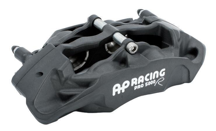
The Pro 5000) range is an entry level option of Radi-CAL™ brake calipers. and is developed from our experience in all areas of motorsport, these forged designed, internally ported calipers feature the latest innovations from our pioneering Radi-CAL™ asymmetric design concept.
RANGE DETAILS
◘ The main objective of the range is to provide a high quality “off the shelf” Radi-CAL™ brake system at a competitive price. The range will be kept to the part numbers listed in this catalogue/website and no variations are available.
◘ Consisting of 13 caliper variants and 18 different discs, which cover 6 & 4 piston calipers and ventilated discs from Ø390mm to Ø280mm and 36mm down to 18mm thickness.
◘ The 13 caliper variants are based on radially mounted two piece forged aluminium calipers and are fitted with 4lb anti-knockback springs (where applicable) with stainless steel pistons on all. Alternative strength anti-knockback springs are also available.
◘ All of the range is available with either Hard Anodised or ENP (Nickel Plated) surface treatments. Check website or contact AP Racing technical support for assistance.
◘ This section provides the basic installation dimensions for both the calipers and the discs, full customer drawing are available on www.apracing.com
4 Piston Front / Rear - To suit Ø330 max / Ø315 min x 28mm discs
General motorsport front and or rear.
- Radial mount, 152mm x 44mm centres.
- Suits Ø330mm max / Ø315mm min x 28mm discs.
- Stainless Steel pistons fitted.
- Stainless Steel wear plates.
- For Nickel plated calipers add “N” to the end of part number e.g. CP9440-2S4LN
- Suits disc up to Ø390mm max / Ø362 min x 36 or 32mm thicknesses.
- Stainless Steel pistons fitted.
- Stainless Steel wear plates.
- For Nickel plated calipers add “N” to the end of part number e.g. CP9665-2S7LN
RH
CP9665-2S7L
LH
CP9665-3S7L
- Pad thickness: 25.0mm
- Pad area: 81.6cm² - Pad volume: 164.3cm³
- General motorsport front. - Radial mount. - Suits disc up to Ø378mm max / Ø362 min x 34mm thicknesses. - Bolted pad retainer with Quick release clip. - Stainless Steel pistons & wear plates fitted. - For Nickel plated calipers add “N” to the end of part number e.g. CP9667-2S7LN
RACE BRAKE CALIPERS
Front & Rear - 6 Piston - 180mm centres - 25mm thick pad
Front & Rear 6 Piston
APPLICATIONS
- General motorsport front.
FEATURES
- Radial mount.
- CP9669 designed for rear applications.
- Suits disc up to Ø390mm max / Ø362 min x 36 or 32mm thicknesses.
- Bolted pad retainer with Quick release clip.
- Stainless Steel pistons & wear plates fitted.
CP9668 TECHNICAL SPECIFICATIONS - All Dimensions in mm unless stated Pistons (mm) Weight (No pads) Hydraulic Threads Radial Mounting (mm) Size Ø x 2AreaCentresOff
- CP6120 & CP6121 suitable for solid disc up to Ø282mm x 12.7mm max thickness.
- CP6126 suitable for ventilated disc up to Ø280mm x 17.8mm max thickness.
- High temperature / low drag seals fitted as standard.
- Aluminium pistons.
- Version with pipe protection available for CP6120 family only.
Solid disc calipers with:Ø44.5mm pistons
- CP6120-2S0 RHT/LHT
- CP6120-3S0 RHL/LHL
- Ø38.1mm pistons
- CP6121-2S0 RHT/LHT
- CP6121-3S0 RHL/LHL
Vented disc calipers:
- CP6126-2S4 RHT/LHT
- CP6126-3S4 RHL/LHL
- Pad Thickness: 14.3mm
- Pad Area: 33.7cm²
- Pad Volume: 50.0cm³
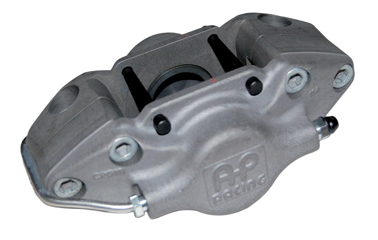
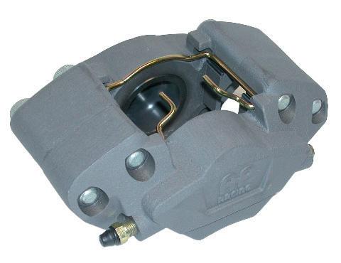
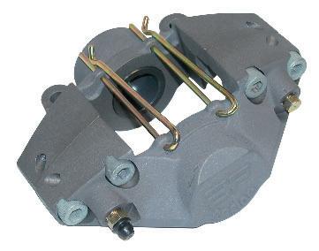
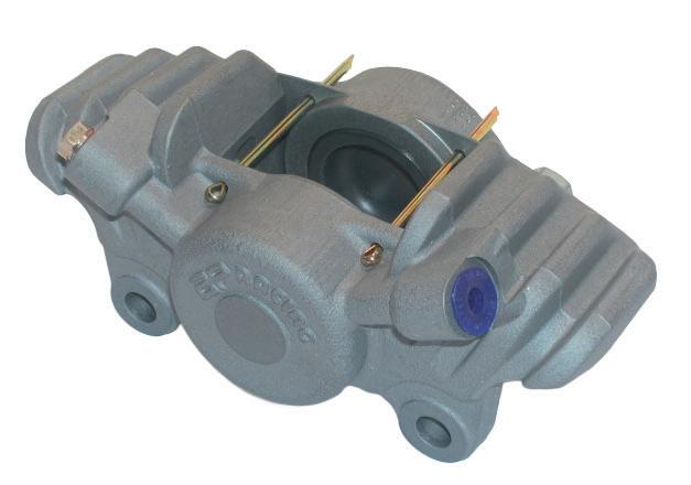
AP Racing’s “Historic” Range of calipers are detailed on pages 16 & 17. These “Classic” items, such as CP2383 and CP2561 and have been reintroduced due to the popularity of various historic racing categories. The “Historic” Range of calipers are usually made to order, however some calipers are stock items, please check availability with AP Racing first.
- CP2382, Escort
Rear, Grp 4 Rally Vented Disc.
- CP2383, Escort
Rear, Grp 4 Rally Solid Disc.
rp 4 Escort ra y
Grp 4 Escort rally - 2 Piston - Lug mount - for solid & ventilated discs
- Pad Thickness: 20.4mm -Pad Area: 57.4cm² -Pad Depth: 50.3mm
Rally / Sports GT - 4 Piston - Suits 13” Wheels
Rally.
(mm)
RACE BRAKE CALIPERS Motorcycle and Formula Student
- Solo & Classic machines.
- Superbike.
Classic Solo or Sidecar - 2 Piston
- F2 Sidecar. - Road. The original classic design. - Disc diameter & thickness - Ø304mm x 6.4mm - Aluminium alloy body. - Machined from high quality die castings.
- Aluminium alloy pistons.
- Split pin pad retainer.
- Non handed.
- FSAE (Formula Student)
- Road.
CP2696-38E0
Superbike rear / Formula student - 2 Piston front & rear
- Aluminium alloy body.
- CNC machined from billet.
- Disc diameter & thickness - Ø220mm x 4.0mm
- Aluminium alloy pistons.
- Lightweight.
- ‘R’ Clip quick release pad retainer.
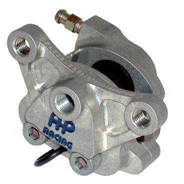
CP4226-2S0
- Pad Thickness: 7.0mm
- Pad Area: 9.4cm² -Pad Depth: 26.8mm
- Superbike.
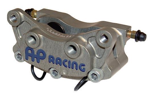
Superbike 2 x 2 Piston rear or Formula Student 4 Piston front
- FSAE (Formula Student) - Road.
- Dual circuit caliper designed to allow the use of both a foot and thumb master cylinder.
- Two piece aluminium alloy body. - Machined from billet.
Retainer R Clip - CP3696-106
- Disc diameter & thickness - Ø320mm x 6.0mm. - Differential bores for extended pad life. - Aluminium alloy pistons. - Pad anti-rattle clip fitted. - ‘R’ Clip quick release pad retainer. - RH -
ROADCAR UPGRADE BRAKE CALIPERS
General Information
INTRODUCTION
Competition is the ultimate testbed — and AP Racing’s extensive involvement in motorsport continues to deliver benefits across high-performance road cars, upgrades, and armoured vehicles.
While the demands of modern road use may differ from those on the track, the core requirements remain the same: performance, reliability, and control.
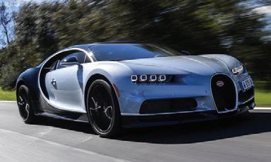
With a dedicated team of engineers and designers focused on road car and armoured applications, AP Racing brings extraordinary capability to exceptional marques such as Ariel, Aston Martin, BAC, Bugatti, Caterham, Ford, Koenigsegg, and Lotus, to name a few. Whether it’s brakes or clutches, AP Racing is proud to work with such prestigious brands.
Our proven systems and tailored approach allow us to offer outstanding service as a trusted supplier for OE, upgrade, armoured, and special project brake systems.
SPECIAL VEHICLES
AP Racing has engineered unique solutions for various “Special Vehicles” sectors—including armoured/defence, hybrid, electric, land speed, bomb disposal, and even aerospace—tailored to each customer’s specific criteria and requirements.
With a range of brake systems built for different duty levels, our solutions are designed and developed using vehicle testing procedures that replicate real-world environments and scenarios. Drawing from extensive motorsport and OEM experience, AP Racing consistently delivers proven, high-performance brake and clutch packages for a diverse range of vehicles.
Contact: Matthew Dodd, Account Engineer – Specialty OE, for further details and technical information: Tel.: +44 (0)24 7688 3339 / E-Mail: matthew.dodd@apracing.co.uk
THE RANGE
The calipers featured on pages 21 to 30 represent the most popular options from our performance upgrade range, though not all available models are listed. If your requirements differ from those shown, please contact AP Racing’s Road Car technical support for further assistance.
DESIGN & DEVELOPMENT
The entire design and development process is carried out at our headquarters in Coventry. With two brake dynamometers and an NVH dynamometer on-site, we can replicate the most demanding test environments. AP Racing’s designers use the latest computer-aided technology to create brake calipers that are not only high-performing and visually striking, but also competitively priced to meet market demands.
MANUFACTURING
The introduction of a purpose-built, semi-automated manufacturing facility for AP Racing’s Road car and upgrade products allow us to take full advantage of the latest manufacturing techniques and systems. This provides AP Racing with the capability to produce brake calipers for vehicle models with production volumes of up to 20,000 units per annum.
IMPORTANT SAFETY NOTE FOR CUSTOMERS
All AP Racing brake calipers are designed and exhaustively tested to ensure they meet a set of specified parameters for both strength and durability. It is important when selecting a brake caliper to ensure that the relevant operating parameters are not exceeded on the application on which the product is to be installed.
Technical Data Sheets for upgrade calipers can be found on our website for most calipers listed but not for all currently. It is the responsibility of the person specifying these products for a given application to ensure that the design parameters of the product are not exceeded. Please contact AP Racing technical department if the proposed caliper does not have this data available.
TECHNICAL DATA SHEETS - BRAKE CALIPERS
Each technical data sheet is specific to a caliper or family of calipers and details the maximum working pressure and maximum brake torque for each caliper. In addition they also include a guide to the typical gross vehicle weight to which this relates. These guides assume the application to be a standard passenger vehicle fitted with road tyres and therefore deceleration rates above 13m/s² (1.3g) will not be achievable.
- If you have any doubts about your installations, operations or maintenance of AP Racing brake calipers call or e-mail the following addresses: roadtech@apracing.co.uk or telephone our technical support on +44 (0)247663 9595
PERFORMANCE UPGRADE BRAKE CALIPERS
World Radi-CAL™ Introduction and Forged 10 & Brake Calipers
WORLD )*™ INTRODUCTION
Following the success of AP Racing’s motorsport Radi-CAL™ ranges, the same design philosophy has been applied to the OEM road and performance upgrade markets in the form of the World Radi-CAL™ range. This includes WR1, WR2, Mono R, Radi-CAL™ X, and the new Radi-CAL™ e, Mono e, and Forged 10 calipers. These 4, 6, and 10 piston forged calipers incorporate AP Racing’s patented technology, enabling road users to experience the superior performance that Radi-CAL™ technology delivers.
These calipers are specifically designed to meet the demands of road applications and include features such as dirt seals, an attractive painted finish, noise abatement solutions, and low-drag seal technology. The latest additions to our performance upgrade family include the 4 and 6 piston Radi-CAL™ e range and our first 10-piston upgrade calipers, Mono e and Forged 10.
In addition, a heavy-duty forged steel caliper has been developed specifically for SUV applications.
All are an evolution of AP Racing’s forging expertise, with Radi-CAL™ e specifically designed for electric vehicle users who want to maintain or improve their low-drag efficiency while upgrading braking performance. While this family shares certain elements with other upgrade calipers, Radi-CAL™ e stands apart with its unique seal technology, distinctive branding, and a choice of advanced gloss black, green, red, silver, yellow, or white anti-corrosion finishes. All calipers are supplied with brake pads fitted.
The Forged 10 caliper is derived from a highly successful OEM variant, allowing AP Racing to offer upgrade customers a solution for applications using Ø420mm x 40mm discs. Unlike other calipers in the upgrade family, the Forged 10 is available only in black, red, or white finishes and is also supplied with pads pre-fitted.
Offering reduced mass, increased rigidity, and improved cooling compared to conventional caliper designs, the Radi-CAL™ concept represents a major innovation in braking technology. First developed by AP Racing in 2007 for motorsport, Radi-CAL™ has since evolved into over 200 Generation 1 and 2 caliper designs for race, OEM, and performance upgrade markets. Generation 2 calipers offer increased rigidity and reduced weight compared to Generation 1 variants.
AP Racing continually refines its Radi-CAL™ caliper technology, which is protected by patents across Europe and in key global markets including the USA, China, and Japan. To complement these calipers, AP Racing also supplies a comprehensive range of discs, pads, and brake fluids. For optimum performance and comfort, AP Racing always recommends using our brake discs, pads, and fluids in combination with our calipers. For more detailed information, please contact the AP Racing technical support team for further assistance.
TYPICAL APPLICATIONS
- Road upgrade.
- See website for vehicles weights specifications.
Forged 10 - 10 Piston - Suits Ø420mm discs
- Forged Monobloc, (one piece) aluminium alloy body, for more dynamic performance.
- Suits Ø420mm max or Ø390mm min x 40mm Iron thick discs.
- Radial mount, 240mm x 55.2mm centres.
- Aluminium alloy pistons.
- Boot type dirt seals fitted.
- Advanced gloss black, red or white anti-corrosion paint finishes.
- Pad anti-rattle clip fitted.
- For black calipers:
RHT - CP7410-2ABG14
LHT - CP7410-3ABG14
RHL - CP7410-4ABG14
LHL - CP7410-5ABG14
- For red calipers: Add ‘R45’ to end of part numbers e.g. CP7410-2AR45
- For white calipers: Add ‘W1’ to end of part numbers e.g. CP7410-2AW1
Mono - 10 Piston - Suits Ø420mm discs for electric vehicles
- Road upgrade for electric vehicles.
- See website for vehicles weights specifications.
- Special low drag seal and groove technology.
- Low drag brake pad shim technology applied.
- Caliper is supplied with brake pads.
- Forged Monobloc, (one piece) aluminium alloy body, for more dynamic performance.
- Suits Ø420mm max or Ø390mm min x 40mm Iron thick discs.
- Boot type dirt seals fitted.
- Advanced gloss black, green, red or white anti-corrosion paint finishes.
- Pad anti-rattle clip fitted.
- For black calipers: RHT - CP7411-2ABG20 / LHT - CP7411-3ABG20 RHL - CP7411-4ABG20 / LHL - CP7411-5ABG20
- For green calipers: Add ‘GN26’ to end of part numbers e.g. CP7411-2AGN26
- For red calipers: Add ‘R42’ to end of part numbers e.g. CP7411-2AR42
- For white calipers: Add ‘W2’ to end of part numbers e.g. CP7411-2AW2
ELECTRIC CAR UPGRADE BRAKE CALIPERS
Mono - 6 Piston & WR2 Radi-CAL™
Mono - Generation 2 - 6 Piston
- Special low drag seal and groove technology.
- Caliper is supplied with brake pads.
- Road upgrade for electric vehicles.
- Front, CP9370.
- Rear, CP9371 and CP9372
- See website for vehicles weights specifications.
- Forged Monobloc, (one piece) aluminium alloy body, for more dynamic performance.
- Suits Ø410mm max or Ø370mm min x 36mm max or 35mm min thick discs.
- Radial mount, 195.0mm x 49.5mm centres.
- Aluminium alloy pistons.
- Boot type dirt seals fitted.
- Advanced gloss black, green, red, silver, yellow or white anti-corrosion paint finishes.
- For green calipers: add ‘GN26’ to end of part numbers e.g.
CP9330-2AGN26
- For red calipers: add ‘R42’ to end of part numbers e.g.
CP9330-2AR42
- For silver calipers: add ‘S29’ to end of part numbers e.g.
CP9330-2AS29
- For yellow calipers: add ‘Y31’ to end of part numbers e.g.
CP9330-2AY31
- For white calipers: add ‘W2’ to end of part numbers e.g.
CP9330-2AW2
PERFORMANCE UPGRADE STEEL BRAKE CALIPERS
Heavy Duty & Super Duty Radi-CAL™ X
AP Racing Radi-CAL™ X calipers are designed to provide a cost-effective and high-performance braking solution for SUVs, Armoured, Military, and similar vehicle platforms. Crafted using AP Racing’s advanced forging techniques, this steel caliper combines high-quality construction, high performance, and long-term durability with visually striking aesthetics. They deliver superior braking performance, specifically tailored for the demands of the SUV, Armoured, and Military markets, ensuring excellent braking power and safety.
Key Features of the Radi-CAL™ X range:
• Six pistons for enhanced braking power and control.
• Two-piece forged steel construction offering superior strength and durability.
• Radial mounting for improved braking efficiency and response.
-For red calipers: Add ‘R28’ to end of part numbers e.g. CP9560-2S0R28
- For silver calipers: Add ‘S10’ to end of part numbers e.g. CP9560-2S010 - For yellow calipers: Add ‘Y23’ to end of part numbers e.g. CP9560-2S0Y23 - For white calipers: Add ‘W1’ to end of part numbers e.g. CP9560-2S0W1
- For red calipers: add ‘R2’ to end of part numbers e.g. CP9200-2S0R2 or CP9202-2S0R2
- For yellow calipers: add ‘Y34’ to end of part numbers e.g. CP9200-2AY34 or CP9202-2AY34
- For white calipers: add ‘W8’ to end of part numbers e.g. CP9200-2AW8 or CP9202-2AW8
PERFORMANCE UPGRADE BRAKE CALIPERS
CP7600 - 4 Piston - 130mm radial mount - Suits Ø295 x 24.0mm discs
- Road upgrade front or rear.
- Cast two piece Aluminium alloy body.
- Suits Ø295mm x 24mm ventilated iron discs.
- Radial mount, 130mm x 47.4mm centres.
- Boot type dirt seals fitted.
- Advanced black or red paint finish, protects against corrosion.
- Aluminium pistons, fitted with dirt seals.
- Stainless steel wear plates.
- Pad anti-rattle clip fitted.
- For black calipers:
- RHT CP7600-2ABK2
- LHT CP7600-3ABK2
- RHL CP7600-4ABK2
- LHL CP7600-5ABK2
- For red calipers: add ‘R2’ to end of part numbers e.g. CP7600-2S0R2
- Pad Thickness: 16.0mm
-
-
CP5100 - 4 Piston - 130mm radial mount - Suits Ø295 x
- Cast two piece Aluminium alloy body.
- Suits Ø295.0 x 25.4mm ventilated iron discs.
- Radial mount, 130mm x 47.4mm centres.
- Road upgrade front & rear.
- Advanced black or red paint finish, protects against corrosion.
- Aluminium pistons, fitted with dirt seals.
- Stainless steel wear plates.
- Pad anti-rattle clip fitted.
- 4lb Anti-knockback springs fitted.
discs
- For black calipers: - RHT CP5100-806S4 / - LHT -807S4 / - RHL -808S4
- LHL -809S4
- For red calipers: add ‘R2’ to end of part numbers e.g. CP5100-802S4R2
- Cast two piece Aluminium alloy body.
- Suits Ø332mm x 26mm disc.
- Radial mount, 130mm x 27.5mm centres.
- Road upgrade front & rear.
- Advanced black or red, matt or gloss paint finishes, protects against corrosion available.
- Aluminium pistons, fitted with dirt seals.
- Pad supports fitted.
- Pin pad retainer with ‘R’ Clip.
- Pad anti-rattle clip fitted.
- For matt black calipers with Ø38.1mm pistons: - RHT / RHL CP5316-2BK2 /- LHT / LHL CP5316-3BK2
- For matt black calipers with Ø41.3mm pistons: - RHT / RHL CP5317-2BK2 /- LHT / LHL CP5317-3BK2
- For gloss black calipers: add ‘BG19’ to end of part numbers e.g. CP5316-2ABG19
- For gloss red calipers: add ‘R2’ to
BRAKE CALIPERS
Technical Information & Caliper Seal on PistonType
RECOMMENDED TIGHTENING TORQUES
AP Racing recommended tightening torques for the following products: ProductTorqueProductTorque
◘ M6 & ¼ UNF Pad Retaining Bolts:
◘ M4 Pad abutment cap head screws: (Use Loctite 242)
◘ M4 wear sensor clamp screw: (Use Loctite 243)
◘ Cross pipe tube nuts: (Use Loctite 648 inside tube nuts, with 7649 activator) - For race calipers only.
◘ 3/8”UNF & M10 Adaptors and Banjo bolts:
With one copper washer
- Resulting maximum torque must not exceed 30.0Nm
◘ CP6300 Dry Break Connector into caliper: (Loctite 270 can be used 13.0Nm
Important Note - For road caliper cross pipes, contact AP Racing technical support for guidance. ◘ Dry Break connector cap:
BASIC DIMENSIONS
The drawing below offers a brief explanation of basic AP Racing Drawing dimensions.
Dimension:Descriptions:
PL Top of the pad material to mounting hole boss face, (hole centreline on lug type calipers).
C Offset - Disc centre line to centre of mounting hole (mounting face on lug type calipers)
D Mounting hole centres.
H Mounting hole diameters.
E Disc width.
U Wheel centre to caliper mounting hole boss. (disc diameter / 2 - ‘PL’ dimension).
Bleed Screws:
DISC PATHWAY CLEARANCE
Disc diameter clearance should be 2.5mm nominal from disc outside diameter to caliper pathway. The clearance can be reduced to 1.8mm minimum for smaller diameter discs (Ø280mm and lower). It is recommended that the tighter clearance is only used with radial mounted calipers where some degree of adjustment by using shims can be achieved if required.
REPLACEMENT CALIPER SEALS
Brake calipers are a safety critical item and AP Racing recommend that calipers are reconditioned and piston seals inspected regularly to maintain optimum performance. Where calipers have been subjected to high temperatures or have been used in adverse conditions e.g. Off Road / Rallying, the calipers should be reconditioned and seals replaced more frequently, to ensure that safety and performance levels are maintained. When cleaning calipers use warm soapy water or an alcohol based cleaning fluid e.g. Methylated Spirits.
DO NOTUSE PETROL, GASOLINE OR MINERAL OIL CLEANER / LUBRICATE as this will damage the seals. Replacement seal kits are available for all AP Racing brake calipers. Depending on the seal type being replaced the following recommended procedures should be followed. To find correct seal kit see page 34.
ANTI-KNOCKBACK SPRINGS
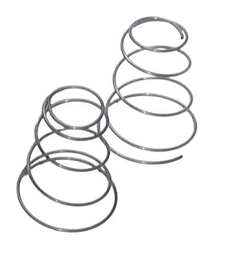
A range of anti-knockback springs are available for use with AP Racing calipers. The spring is located behind the piston in the caliper bore and is designed to counteract pad knock off The springs are available in four loads indicated in lbs/f (force) with 2 sizes dependant upon piston diameter.
4lbsCP2632-11338.43 & 0.91CP2667-10539.88 & 1.22
7lbsCP4100-12139.88 & 1.02CP2667-11339.88 & 1.29
9lbsCP3432-13449.02 & 1.02CP2667-12570.36 & 1.29
12lbsCP2632-13058.50 & 1.29CP2667-15470.36 &
Anti-Knockback Spring Kits.
CP6518-4LBSS4 x CP2632-113
CP6518-4LBLL4 x CP2667-105
4 Piston
6 Piston
CP6518-7LBLL4 x CP2667-113
CP6518-9LBLL4 x CP2667-125
CP6518-4LBSSL4 x CP2632-113 & 2 x CP2667-105
CP6518-7LBSSL4 x CP4100-121 & 2 x CP2667-113
CP6518-9LBSSL4 x CP3432-134 & 2 x CP2667-125
CP4509 (SEAL ON PISTON)
1) Soak new seals in brake fluid for minimum of 30 minutes.
2) Clean brake caliper with warm soapy water and dry off
3) With the pads removed insert a brake disc or block into the centre of the caliper. Using either hydraulic pressure or compressed air carefully extend all pistons against the disc or block. Remove block and remove pistons. Keep all body parts away from escaping air and caliper pistons.
CAUTION: Your caliper is fitted with a glyd ring just inside the opening of each caliper bore. This ring should be examined and replaced if caliper has been subjected to high temperatures or used in adverse conditions e.g. Off road / rallying or not changed for a year.
4) Carefully remove old seals from piston with a narrow blunt edged tool.
5) Ensure that caliper bores, seal grooves and pistons are clean and free from debris and moisture. Use only Alcohol based cleaning fluid, not mineral oil.
6) Carefully fit replacement seal into groove on piston ensuring that it seats correctly in the groove. Check seals are free from damage and correctly seated in groove not twisted or kinked.
7) Carefully engage piston into caliper bore and using a suitable rigid flat bar to apply even pressure, push pistons fully into body. N.B. Excessive force should not be necessary. If piston does not slide smoothly into bore remove & check seal has been fitted correctly.
BRAKE CALIPERS
Seal In Bore and Boot Type Caliper Seal Types
CP4518 & CP8518 ( SEAL IN BORE)
1) Soak new seals in brake fluid for minimum of 30 minutes.
2) Clean brake caliper with warm soapy water and dry off
3) With the pads removed insert a brake disc or block into the centre of the caliper. Using either hydraulic pressure or compressed air carefully extend all pistons against the disc or block. Remove block and remove pistons. Keep allbody parts away from escaping air and caliper pistons.
4) Carefully remove old seals with a narrow blunt edged tool.
5) Ensure that caliper bores, seal grooves and pistons are clean and free from debris and moisture. Use only Alcohol based cleaning fluid, not mineral oil.
6) Carefully fit replacement seal into groove in caliper body ensuring that it seats correctly in the groove. Check seals are free from damage and correctly seated in groove not twisted or kinked.
7) Carefully engage piston into caliper bore and using a suitable rigid flat bar to apply even pressure, push pistons fully into body.
N.B. Excessive force should not be necessary. If piston does not slide smoothly into bore remove & check seal has been fitted correctly.
CP4519 (SEAL IN BORE WITH DIRT SEAL)
1) Soak new pressure seals in brake fluid for minimum of 30 minutes. Do not soak dirt seals (double lip).
2) Clean brake caliper with warm soapy water and dry off
3) With the pads removed insert a brake disc or block into the centre of the caliper. Using either hydraulic pressure or compressed air carefully extend all pistons against the disc or block. Remove block and remove pistons. Keep all body parts away from escaping air and caliper pistons.
4) Carefully remove both old seals with a narrow blunt edged tool.
5) Ensure that caliper bores, seal grooves and pistons are clean and free from debris and moisture. Use only Alcohol based cleaning fluid, not mineral oil.
6) Carefully fit both replacement seals into groove in caliper body ensuring that they seat correctly in the grooves. Check seals are free from damage and correctly seated in grooves not twisted or kinked.
7) Carefully engage piston into caliper bore and using a suitable rigid flat bar to apply even pressure, push pistons fully into body. N.B. Excessive force should not be necessary. If piston does not slide smoothly into bore remove & check seals has been fitted correctly.
CP4525 & CP4527 (BOOT TYPE WITH DIRT SEAL)
Removal: Before removal procedure begins the brake caliper should be thoroughly cleaned using warm soapy water only. Ensure that all hydraulic ports are sealed before cleaning and dry caliper thoroughly before work begins.
Do not use chemical cleaners of any kind or petrol/gasoline or mineral oil based, as these will cause permanent damage to the new seals.
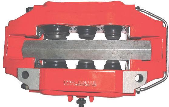
1) Use a reaction block selected to fill the full width of the caliper pathway as shown in fig.1. This block must span the length of the caliper opening and be well supported between the brake pad abutments at either end of the caliper.
2) Loosely insert a hydraulic fitting (M10x1.0) into the caliper feed port as shown in fig.2 (a spare Bleed Screw loosely fitted will suffice). Do not tighten to form a seal.
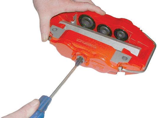
3) Press a hand held air gun against the fitting as shown in fig.3 and allow a short, high pressure burst of air to enter the caliper (a perfect seal between the air gun and fitting is neither necessary or advisable). Keep all body parts away from escaping air andcaliper pistons.
4) A single burst of air should be sufficient to extend all pistons at once as shown in fig.4. If one or more pistons remain jammed in the caliper body after repeating this step then the caliper may need to be returned to AP Racing for assessment. Please contact AP Racing technical support for assistance.
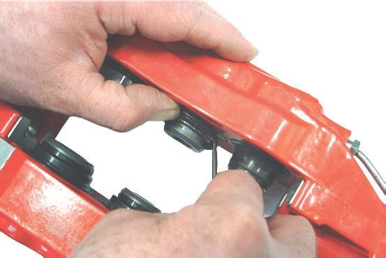
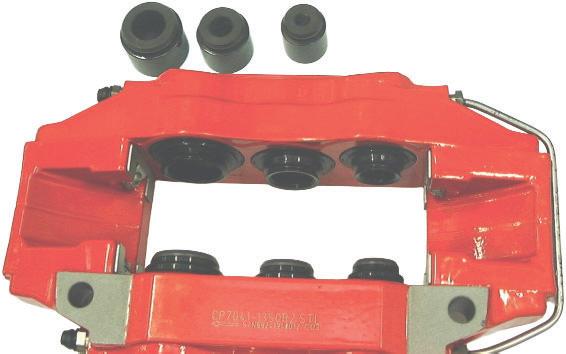
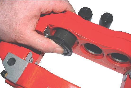
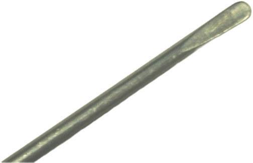
5) Remove reaction block. It is possible that the dirt seals may become detached from the caliper body at this point. If so the pistons can be carefully pulled from the caliper body with dirt seals attached. It is also possible that the dirt seal may become detached from the piston, in which case the piston should be pulled through the dirt seal to remove. Where dirt seal remains attached to both piston and caliper body a small blunt instrument (such as a rounded off screwdriver, see fig.10) should be used to carefully release the dirt seal from the piston, as shown in fig.5
6)Fig.6 shows pistons removed with dirt seals remaining attached to caliper body.
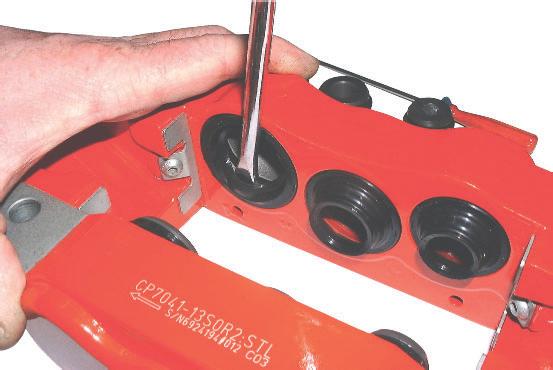
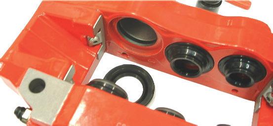
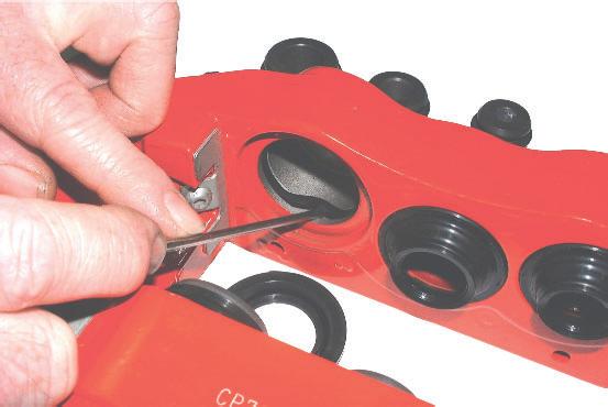
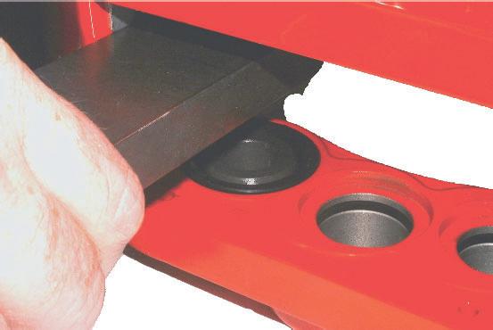
7) The dirt seal can now be removed by carefully inserting a narrow, blunt blade (such as a medium sized screwdriver) through the seal opening and between the outer ring of the seal and the back wall of the dirt seal recess as shown in fig.7. By gently turning the screwdriver the seal should work free. Only very light force is required to perform this operation. Never use excessive force as damage to caliper body may result.
8) Once dirt seal is removed the pressure seal will be exposed, located in the groove in the caliper body as shown in fig.8
9) Using the small blunt instrument from step 5 (see fig.10), carefully remove the pressure seal from the caliper body as shown in fig.9
Continued overleaf...
fig
fig
BRAKE CALIPERS
Boot Type Caliper Seal Types & Seal Ordering
10) All dirt and pressure seals should be removed from the caliper by following the above procedure. Before new seals are fitted, all pistons and the caliper body should be inspected for damage. If damage of any kind is present on either the caliper bores orpiston outer diameters the caliper should be considered unfit foruse and either replaced of returned to AP Racing for assessment.If in doubt regarding any aspect of caliper safety please contactAP Racing technical support for assistance.
Refitting:
11) Before re-assembly ensure that all parts are perfectly clean and free from debris or moisture. Replacement pressure seals should be soaked in AP Racing brake fluid for 30 minutes prior to fitment. Do not remove excess brake fluid as the excess will aid fitment of pistons. Do not soak dirt seals.
12) Carefully fit pressure seal into groove in caliper body ensuring that it seats correctly in the groove. Seal should be free from damage and not be twisted or kinked. Pre-assemble dirt seal on piston (seal locates in groove on piston end). Carefully slide piston into caliper bore (pressure seal must already have been installed as shown in fig.11. Only light pressure applied by hand is required. If piston does not slide easily into place, remove and inspect parts. If difficulty is experienced when installing pistons please contact AP Racing technical support for assistance.
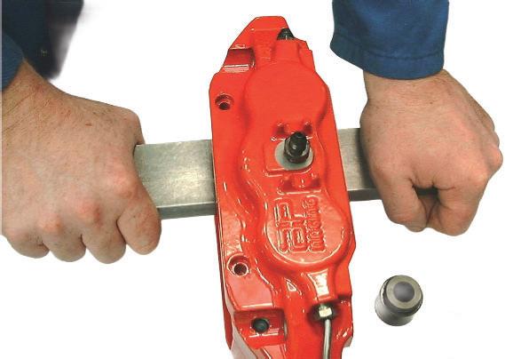
13) The dirt seals can now be pressed into caliper body. Carefully locate seal in caliper body using finger pressure only. Then select a suitable rigid, flat bar or similar as shown in fig.12, and position to cover dirt seal.
14) Apply slow and even pressure to dirt seal using bar as shown in fig.13, care must be taken to ensure that dirt seal is inserted square to the caliper body.
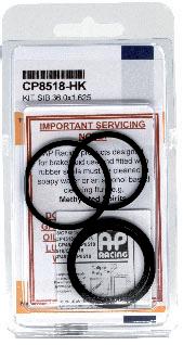
15) On correct installation, the dirt seal should sit flush with the caliper body as shown in fig.14. Repeat steps 12 to 15 to fit all remaining pistons and seals.Once calipers are refitted to vehicle a pressure test should be carried out to check for leaks. With the engine running press the brake pedal and hold at a constant load for 60 seconds. No ‘sinking’ of the brake pedal should occur. If the pedal does ‘sink’ (travel further when under constant/steady load) it should be considered that a leak in the brake system is present. If a leak is suspected, check all hydraulic joints and inspect re-conditioned calipers. If cause of leak cannot be identified contact AP Racing technical support for assistance before vehicle is used. The repair kit may also contain 2 off small ‘O’Rings for replacement of Bleed Screw seals where fitted. There may also be replacement Bleed Screw dust caps included. Where included these parts should be fitted to the brake caliper.Replacement seal kit details for all piston configurations used in AP Racing brake calipers “seal in bore”, “seal on piston” and “seal in bore with dirt seals” are given in the table on page 34.
ORDERING
To determine the correct seal kit proceed as follows:-
1) If you know the part number of your caliper then determine the correct part number of the kit required by referring to the individual caliper listings.
2) If you do not know the part number of your caliper then proceed as follows:-
a) Measure the nominal piston diameters.
b) Determine the type by comparison with the drawings on pages 31 / 33.
c) Look at the column (caliper bore in mm) identify your sizes. The relevant kit number can be found on the right.
d) When ordering please quote the seal kit part no, given from the relevant table, then contact your nearest AP Racing distributor or dealer for availability.
3) Each kit contains seals to repair one caliper:-
a) One letter after Kit Nos = 2 seals, e.g. -J
b) Two letters after Kit Nos= 4 seals, e.g. -JJ
c) Three letters after Kit Nos = 6 seals, e.g. -CEJ
d) Four letters after kit Nos = 8 seals, e.g. -AEAE NB. Kits are priced more competitively compared to purchasing individual seals.
NB. With CP4519, CP4525 and CP4527 seal kits, the appropriate number of dirt seals and or boot seals are also included.
NB. Kits contain one caliper set of seals e.g. 2, 4, 6, or 8.
Contact your nearest official distributor for quotes and to order. Distributor list can be found via this link - https://apracing.com/find-a-dealer
CUSTOMER NOTES
fig 9.
fig 11.fig 12.
fig 13.fig 14.
BRAKE CALIPERS
Replacement Caliper Seals
Caliper Bore identification Letters and Size Reference mm (inch)
AP Racing has compiled a spare parts section to help our customers identify replacement parts, such as pistons, seal repair kits, pad retainers, wear plates, bleedscrews and fluid pipes (Pipes for race calipers ONLY, see note below) for not only the brake calipers in this publication, but also for those that are NOT included but still in production, and those that have been obsoleted over recent years.
NOTE: Road/Performance replacement fluid pipes are not available for individual sale, and should be return to AP Racing for replacements.
The obsolete brake calipers may or may not have the individual components still available, but having a reference may help identify alternatives. Please contact AP Racing for information and advice on those calipers, once identified.
These parts are available for sale individually, except those mentioned above. Please contact AP Racing for clarification, whether the part is still available or if it’s been replaced by another, then contact your nearest official distributor for a quote and to purchase.
CP4890-101CP3720-34CP3720-106 x 4 CP3720-16/17S4CP4509-JLCP3720-173CP3720-126CP3720-125
CP3434-118CP3720-34CP3720-106 x 4 CP3720-16/17S4MCP4509-JLCP3720-173CP3720-115CP3720-114 CP3434-118CP3720-34CP3720-106 x 4 CP3720-18/19S4MCP4509-JLCP3720-173CP3720-115CP3720-114
CP4890-101CP3720-34CP3720-106 x 4 CP3720-30/31/32/33S4CP4509-JLCP3720-173CP3720-126CP3720-125 CP3679-117CP3720-38CP3720-106 x 4 CP3720-30/31S4MCP4509-JLCP3720-107CP3720-115CP3720-114
CP3679-117CP3720-38CP3720-106 x 4 CP3720-42/43/44/45S4CP4509-JLCP3720-173CP3720-126CP3720-125
CP3796-20/21/22/23S4CP4509-CEJCP3720-182CP3760-111CP3760-110CP3720-126CP3796-134CP3796-136CP3596-108 x
CP3796-24/25/26/27S4CP4509-CEJCP3720-182CP3760-111CP3760-110CP3720-126CP3796-134CP3796-138CP3596-159 x 4 CP3796-24/25/26/27S4MCP4509-CEJCP3720-182CP3596-130CP3620-103CP3720-115CP3796-134CP3796-138CP3596-159 x 4 CP3796-30/31/32/33S4CP4509-CEJCP3720-182CP3760-111CP3760-110CP3720-126CP3796-135CP3796-137CP3596-159 x 4 CP3798-2/3/4/5S0MCP4518-CECP3720-173CP3798-107CP4296-113
CP3799-109CP3799-6CP3799-111 x 1 / CP3846-101 x 2 / CP3799-110 x
CP3894-12/13/14/15S4CP4509-CEJCP3720-173CP3894-120CP3894-121CP3894-122CP3895-109CP3894-17CP3895-107 x 1 / CP3895-117 x 2 / CP3895-106 x 1 CP3894-14/15S4MCP4509-CEJCP3720-173CP3894-108CP3894-109CP3894-110CP3895-109CP3894-17CP3895-107 x
2 / CP4240-144 x 2 CP4260-30/31/32/33S7MCP4518-CEJCP3880-1CP4960-104CP4960-105CP4960-106CP4240-112CP4260-7CP4240-145 x 2 / CP4240-144 x 2 CP4340-2/3/4/5S7LCP4518-CEJCP3880-1CP4340-106CP4340-107CP5015-107CP4578-101CP4340-10CP4218-125 x 2 & -126 x 1 & -127 x 1 CP4360-10/11S7LCP4518-DEKCP3880-1CP4360-104CP5820-109CP5820-107CP4360-14CP4360-6CP4970-104 x 4 CP4360-20/21S7LCP4518-DEKCP3880-1CP4360-126CP4360-127CP4360-128CP4370-104CP4360-17CP4970-104 x 4 CP4360-2/3/4/5S7LCP4518-DEKCP3880-1CP4360-126CP4360-127CP4360-128CP4360-17CP4970-104 x 4 CP4360-8/9S7LCP4518-DEKCP3880-1CP4360-104CP5820-109CP5820-107CP4360-14CP4360-6CP4970-104 x 4 CP4370-2/3/4/5S7LCP4509-DEKCP3880-1CP4370-105CP4370-106CP4370-107CP4370-104CP4360-17CP4970-104 x 4 CP4380-2/3/4/5S7LCP4518-ACECP3880-1CP4380-101CP4340-106CP4340-107CP4578-101CP4340-10CP4218-125 x 2 & -126 x 1 & -127 x 1
CP4567-110CP4567-7CP4567-120 x 4 / Pad retainer bolt
CP5100-117CP4567-16CP4567-120 x 4 / Pad retainer bolt CP5100-139
CP4567-125CP4567-17CP4567-120 x 4 / Pad retainer bolt CP5689-109
CP5100-116CP4567-6CP4567-120 x 4 / Pad retainer bolt CP5100-210 CP4568-6/7S0LCP4518-EGCP3720-173CP4568-105CP4568-104
CP5100-116CP4567-6CP4567-120 x 4 CP4586-4E0CP4518-HCP3720-182CP3177-102 CP4586-5E7CP4518-HCP3720-182CP3177-102 CP4595-6/7S0LCP4518-EJL92598CP4595-133CP4595-132CP4595-134CP4595-120CP4595-14CP4595-114 x 4
CP5260-2/3/4/5S7LCP4518-CEJCP3880-1CP5260-109CP5260-110CP5260-111CP5260-108CP5260-6CP5260-106 x 4 CP5260-8/9/10/11S7LCP4518-CEJCP3880-1CP5260-109CP5260-110CP5260-111CP4578-101CP5260-12CP5260-106 x
CP5266-2/3/4/5S0MCP4518-GGGCP3720-182CP5166-106
CP5266-6 CP5270-2/3/4/5S7LCP4518-CEJCP3880-1CP5260-109CP5260-110CP5260-111CP4578-101CP5260-12CP5260-106 x 2 / CP5270-104 x 1 / CP5270-105 x 1 CP5300-14/15S4CP4519-KLCP3720-173CP5300-108CP5300-109
CP5309-10CP5309-106 x 1 / CP5309-107 x 1 / CP5320-107 x 2
CP5310-22CP5310-103 x 4
CP5211-10
CP5211-10
CP5315-10
CP5119-144CP5317-10
CP5119-144CP5317-10
CP5119-144CP5317-10
CP5317-10
CP5119-144CP5317-10
CP5309-10CP5309-106 x 1 / CP5309-107 x 1 / CP5320-107 x 2
CP5320-107 x 4
CP5119-144CP5317-10
CP4751-104CP5610-6CP5610-106 x 4
CP5420-4/5S0LCP4518-DECP3880-2CP5825-109CP6261-107CP5420-106 x 1, Ctr beam / CP5880-107 x 4 CP5421-4/5S0LCP4518-CDCP3880-2CP6260-107CP6261-107CP5420-106 x 1, Ctr beam / CP5880-107 x 4
CP4751-104CP5610-6CP5610-106 x 4 CP5515-4/5S0CP4518-DCCP3880-2CP5515-110CP5515-111
CP4751-104CP5610-6CP5610-106 x 4 CP5515-8/9S0CP4518-DCCP3880-2CP5515-110CP5515-111
CP5510-106CP5510-6CP5610-106 x 4 CP5555-12/13/14/15S4CP4519-CEJCP3720-173CP5555-108CP3650-107CP2409-124CP5555-126CP5555-120 x 4 CP5555-2/3S4CP4519-CEJCP3720-173CP5555-108CP3650-107CP2409-124CP5555-109CP5555-120 x 4 CP5555-4/5S7CP4519-CEJCP3720-173CP5555-108CP3650-107CP2409-124CP5555-109CP5555-120 x 4 CP5555-66/67/68/69S4CP4519-CEJCP3720-173CP5555-108CP3650-107CP2409-124CP5555-126CP5555-120 x 4 CP5555-802/3/4/5S4 / R2 & VGCP4519-CEJCP3720-173CP5555-108CP3650-107CP2409-124CP5555-109CP5555-120 x 4 CP5555-806/807/808/809S4CP4519-CEJCP3720-173CP5555-108CP3650-107CP2409-124CP5555-126CP5555-120 x 4 CP5555-808/809/810/811S4R2&VGCP4519-CEJCP3720-173CP5555-108CP3650-107CP2409-124CP5555-126CP5555-120 x 4 CP5555-810/811/812/813S4CP4519-CEJCP3720-173CP5555-108CP3650-107CP2409-124CP5555-126CP5555-120 x 4 CP5555-814/5/6/7S4 / R2 & VGCP4519-CEJCP3720-173CP5555-108CP3650-107CP2409-124CP5555-126CP5555-120 x 4 CP5555-818/819S4CP4519-CEJCP3720-173CP5555-108CP3650-107CP2409-124CP5555-126CP5555-120 x 4 CP5555-824/825S4CP4519-CEJCP3720-173CP5555-108CP3650-107CP2409-124CP5555-126CP5555-120 x 4 CP5555-826/827/828/829S4CP4519-CEJCP3720-173CP5555-108CP3650-107CP2409-124CP5555-126
CP5555-120 x 4 CP5555-830/831S4 & R2CP4519-CEJCP3720-173CP5555-108CP3650-107CP2409-124CP5555-109CP5555-120 x 4 CP5555-838/839S4CP4519-CEJCP3720-173CP5555-108CP3650-107CP2409-124CP6136-109CP5555-120 x 4 CP5555-84/85S4CP4519-CEJCP3720-173CP5555-108CP3650-107CP2409-124CP5555-155CP5555-174 x 4 CP5560-32/33/34/35S0LCP4518-CEJCP3880-1CP5560-108CP5560-109CP5560-110CP5555-126CP5560-26CP5555-120 x 4 CP5567-2/3S4CP4518-GKCP3880-1CP5567-106CP5567-107CP5567-108 x
CP5570-802/3/4/5S4 / R2 & VGCP4519-CEJCP3720-173CP4689-108CP5145-103CP2889-105CP5200-124CP5555-174 x 4 CP5570-806/807S4 & R2CP4519-CEJCP3720-173CP4689-108CP5145-103CP2889-105CP5200-124CP5555-174 x 4 CP5570-810/811/812/813S4CP4519-CEJCP3720-173CP4689-108CP5145-103CP2889-105CP5555-157CP5555-174 x 4 CP5570-814/815/816/817S4CP4519-CEJCP3720-173CP4689-108CP5145-103CP2889-105CP5200-124CP5555-174 x 4 CP5575-802/3/4/5S4 / R2 & VGCP4519-CEJCP3720-173CP4689-108CP5145-103CP2889-105CP5555-157CP5575-106 x 4 CP5589-2/3/4/5S4CP4518-CEJCP3720-182CP4689-108CP3645-111CP4689-106CP5589-106CP5589-6CP5200-306 x 4 CP5610-2/3/4/5S0LCP4518-EGCP3880-2CP5410-107CP5610-108
CP4751-104CP5610-6CP5610-106 x 4 CP5620-2/3S4CP4509-DDCP3720-173CP3579-108
CP4751-104CP5751-28CP6751-111 x 2 / CP6751-110 x 2
CP5751-109CP5751-29CP6751-111 x
CP5755-108
CP5755-108 CP5755-107 x 4
CP5755-107 x
CP5756-112
CP5755-108 CP5755-107 x
CP5751-109CP5751-29CP6751-111 x
CP4751-104CP5751-28CP6751-111 x 2 / CP6751-110 x 2
CP5751-109CP5751-29CP6751-111 x 2 / CP6751-110 x 2
CP5780-6/7/8/9S0LPCP4518-JLCP6300-21CP5990-106CP5990-107CP5780-104 x 4 / CP5780-105 x 1 Ctr beam
CP5785-2/3/4/5S0LPDCP4528-HLCP5785-106CP5785-107 CP5785-113 x 4 CP5788-2/3/4/5S0LCP4518-JLCP3880-1CP4090-111CP5830-115
CP5788-6CP5788-106 x 4 CP5789-2/3/4/5/S0LPCP4518-JLCP3880-1CP5990-107CP5990-106
CP5789-6CP5789-105 x 4 CP5789-2/3/4/5S0MPCP4518-JLCP3880-1CP5789-107CP5789-106
CP5789-6CP5789-105 x 4 CP5800-12/13S0LCP4518-DEKCP3720-182CP5810-113CP5810-114CP5810-115CP5800-107CP5800-6CP5800-109 x 4 CP5800-2/3/4/5S0LCP4518-DEKCP3720-182CP5810-113CP5810-114CP5810-115CP5800-107CP5800-6CP5800-109 x 4 CP5805-2/3/4/5S0LCP4518-EGLCP3720-182CP4761-111CP4751-129CP5751-145CP4751-104CP5805-6CP6751-111 x 2 / CP6751-110 x 2 CP5806-2/3S0LCP4518-EGLCP3720-182CP4761-111CP4751-129CP5751-145CP4751-104CP5805-6CP6751-111 x 2 / CP6751-110 x 2 CP5810-2/3/4/5S0LCP4518-DEKCP3880-2CP5810-113CP5810-114CP5810-115
CP5810-6CP5810-105 x 1 / CP5810-104 x 4 CP5810-2/3/4/5S0MCP4518-DEKCP3880-2CP5810-110CP5810-111CP5810-112
CP5810-6CP5810-105 x 1 / CP5810-104 x 4 CP5820-2/3/4/5S0LCP4518-EFKCP3880-2CP5820-109CP5820-107CP5820-108
CP5971-2/3S7MCP4518-BCECP3880-1CP5961-105CP5961-104CP5970-114CP5970-104CP5970-7CP4970-104 x 4 CP5971-4/5S7MCP4518-BCECP3880-1CP5961-105CP5961-104CP5970-114CP5970-104CP5970-8CP4970-104 x 4 CP6016-2/3S0CP6016-51CP3880-1CP6016-106
CP6080-2/3S7MPCP4518-CEJCP3880-1CP6060-122CP6060-120CP6060-121CP6460-105CP6060-6CP6060-107 x 4 CP6080-4/5S7MPCP4518-CEJCP3880-1CP6060-122CP6060-120CP6060-121CP6460-105CP6060-7CP6060-107 x 4 CP6083-2/3S7MCP4518-CEJCP3880-1CP6083-108CP6083-107CP6083-106CP6083-7CP5856-120 x 4 / CP6066-104 x 1 Ctr beam CP6085-2/3S7MCCP4518-CEJCP3880-1CP6055-110CP6055-111CP6055-112
CP6075-6CP6075-106 x 1 / CP6075-105 x 4 CP6085-4/5S7MCCP4518-CEJCP3880-1CP6055-110CP6055-111CP6055-112
CP6075-7CP6075-106 x 1 / CP6075-105 x 4 CP6086-2/3S7MCCP4518-CEJCP3880-1CP6055-110CP6055-111CP6055-112CP6060-107 x 4 / CP6086-104 x 1 CP6087-2/3S7MPCP4518-BCECP3880-1CP6057-104CP6055-110CP6055-111CP6055-107 x
CP6136-4/5S0LCP4518-CDHCP3880-1CP6136-114CP6136-116CP6136-110CP6136-107CP6136-10CP6508-102 x 4 CP6136-8/9S0LCP4518-CDHCP3880-1CP6136-114CP6136-116CP6136-110CP6136-107CP6136-10CP5555-120 x 4 CP6138-2/3S0LCP4518-DEDECP3880-1CP6136-114CP6136-115CP6136-111CP6138-106CP6138-10CP6508-102 x 4
CP6148-2/5R0MCP4518-AEAE
CP6148-3/4R0MCP4518-AEAE
CP6148-108CP6148-109
CP6148-108CP6148-109
CP6148-6CP6148-107 x
CP6148-7CP6148-107 x
/ CP6148-106 x
CP6160-2/3S7MPCP4518-CEJCP3880-1CP6055-110CP6055-111CP6055-112CP6060-107 x 4 / CP6086-104
x 1 / CP5760-105 x 4 CP6215-2/3/4/5S0LCP4518-DGCP3880-1CP6215-106CP6215-105 CP5760-6CP6215-104 x 1 / CP5760-105 x 4 CP6215-6/7/8/9S0LCP4518-DGCP3880-1CP6215-109CP6215-110
CP5760-6CP6215-107 x 2 / CP6215-108 x 2 / CP6215-104 x 1
CP6220-2/3/4/5S0CP4518-CEJCP3720-182CP5070-107CP5070-106CP5070-105CP6220-113CP6220-21CP6220-110 x 4 CP6230-2/3/4/5S7MCP4518-CEJCP3720-173CP4970-113CP4970-112CP4970-111CP6230-112CP6230-21CP6230-111 x 4 CP6238-2/3S0LCP4518-DEDECP3880-1CP6136-114CP6136-115CP6136-111CP6238-106CP6238-10CP6238-110 x 4 CP6240-2/3/4/5S7MCP4518-CEJCP3720-173CP4970-113CP4970-112CP4970-111CP6230-112CP6240-6CP6230-111 x 4 CP6270-2/4S7MP OR CCP4518-DHCP3880-1CP6070-110CP6070-111CP6070-7CP6070-107 x 4 / CP6270-104 x 1 CP6268-12/-13S7LCP8518-EFKCP3880-1CP6268-104CP6268-105CP6268-106CP6268-111 x 4 CP6269CP8518-EFKCP3880-1CP6268-104CP6268-105CP6268-106CP6268-20 / -21Pad Abutment Plates, L = CP6269-102 /
CP6270-3/5S7MP OR CCP4518-DHCP3880-1CP6070-110CP6070-111CP6070-6CP6070-107 x 4 / CP6270-104 x
CP6271-2/3/4/5S7MPCP4518-DHCP3880-1CP6070-110 CP6070-111CP6070-6CP6070-107 x
CP6320-110CP6320-106 x 4 CP6350-14/15S7MCP4518-CEJCP3880-1CP6350-120CP6350-119CP6350-118CP6350-109CP6350-12CP6350-110 x 4 CP6350-18/19S7MCP4518-CEJCP3880-1CP6350-120CP6350-119CP6350-118CP6350-109CP6350-12CP6350-110 x 4 CP6350-2/5S7MCP4518-CEJCP3880-1CP6350-108CP6350-107CP6350-106CP6350-109CP6350-12CP6350-110 x 4 CP6350-3/4S7MCP4518-CEJCP3880-1CP6350-108CP6350-107CP6350-106CP6350-109CP6350-13CP6350-110 x 4 CP6350-8/9S7MCP4518-CEJCP3880-1CP6350-120CP6350-119CP6350-118CP6350-109CP6350-12CP6350-110 x 4 CP6360-2/3S7LCP4518-CEJCP3880-1CP6360-104CP4360-127CP6360-105CP6360-110CP6360-7CP6360-106 x 4 CP6360-4/5S7LCP4518-CEJCP3880-1CP6360-104CP4360-127CP6360-105CP6360-110CP6360-6CP6360-106 x 4 CP6361-2/3S7LCP4518-CEJCP3880-1CP6360-104CP4360-127CP6360-105CP6360-110CP6360-7CP6360-106 x 4 CP6361-4/5S7LCP4518-CEJCP3880-1CP6360-104CP4360-127CP6360-105CP6360-110CP6360-6CP6360-106 x 4 CP6382-2/-3S7LPCP8518-BEHCP6300-30CP6382-201CP6382-202CP6382-203CP6382-207 x 4 CP6420-2/3/4/5R4MCP4518-HL CP3720-177CP6320-107 CP6320-110CP6320-106 x 4
CP7040-16/17/18/19S0CP4525-CEJCP3880-1CP7040-118(6026)CP6609-106(6026)CP6200-104CP7040-110 x 4 CP7040-2/3/4/5S0CP4525-CEJCP3880-1CP7040-118(6026)CP6609-106(6026)CP6200-104CP7040-110 x 4 CP7040-2/3/4/5S0R2CP4525-CEJCP3880-1CP7040-118(6026)CP6609-106(6026)CP6200-104CP7040-110 x 4 CP7041-12/13S0CP4525-CEJCP3880-1CP7040-118(6026)CP6609-106(6026)CP6200-104CP7040-110 x 4 CP7041-12/13S0R2CP4525-CEJCP3880-1CP7040-118(6026)CP6609-106(6026)CP6200-104CP7040-110 x 4 CP7060-2/3S0RDCP4525-CEJCP3880-1CP4910-141CP4910-140CP3344-192CP7060-10CP7040-110 x 4 CP7060-2/3S4 & RDCP4525-CEJCP3880-1CP4910-141CP4910-140CP3344-192CP7060-10CP7040-110 x 4 CP7206-4/5S4CP4525-JKCP3880-1CP4090-112CP5205-101
CP5138-106CP7206-101CP6200-103 x 4 CP7269-2/3S7LCP8518-CEJCP3880-1CP7269-208CP6269-130CP7269-209CP7269-204 x 4 / CP7269-203 x 1 Ctr beam.
CP7410-138 Pad anti-rattle clip
CP7410-2/3/4/5ABG14CP4525-BBB11CP3880-1CP9910-108 x 6CP9910-109 x 4
CP7411-2/3/4/5ABG20CP4525-BBB11CP3880-1CP9910-108 x 6CP9910-109 x 4
CP7480-2/3S7LCP4518-DHCP3880-1CP7480-104CP7480-105CP6269-119 x 4 / CP7480-108 x1 Ctr beam
Experience with the type of installation format is very important and AP Racing has a wealth of knowledge for all types of racing, oem and performance aftermarket sectors.
If you require any selection advice or have any doubts about the installations, operations or maintenance of AP Racing brake discs call or e-mail the following addresses: racetech@apracing.co.uk / roadtech@apracing.co.uk / telephone our technical support on +44 (0)247663 9595
BRAKE DISCS
General Information
INTRODUCTION
The AP Racing range of ventilated and solid brake discs have been developed with the benefit of unparalleled experience in brake technology, to meet the severe demands, encountered under race, rally and road conditions.
RACE: Our extensive range, includes discs to suit all of the most demanding series in the world. Teams competing in F3, WRC, GT and Endurance, Nascar and many global Touring car championships use AP Racing discs.
ROAD: As well as our successes on the circuits & stages of the world, AP Racing has developed disc braking systems for many leading volume & specialist high performance vehicle manufacturers including Aston Martin, Caterham, McLaren, Ford, HSV, Koenigsegg, Morgan, Lotus, & TVR, to name a few.
DESIGN
AP Racing share innovations in the R&D processes between race and road projects, the basic function is the same for both although each has different service requirements.
◘ Race Discs are submitted to high braking and thermal loads. These loads are repeated frequently over many laps or stages. The service life is short, and noise and comfort are not really an issue. Race discs normally employ a separate disc and bell assembly, which are generally available in two types:
- Light Duty - 2 piece bolted assemblies
- Heavy Duty - 2 piece floating assemblies.
A given disc has to fit many different customer cars, so they require custom mounting bells.
◘ Road Discs, however have relatively low and infrequent loads, although vehicle mass increases compared to race cars, which generates high braking torques. Road Discs have comfort and long service life requirements. Costs of each item also have to remain low for the OEM and the end user, when replacement time arrives.
For road cars, many applications use 1 piece disc and bell assemblies, due to high volume production requirements. High performance vehicles and brake kits usually use 2 piece bolted assemblies, enabling a heavy disc fitment similar to a race set-up.
- Light Duty - 1 piece disc and bell assembly
- Heavy Duty - 2 piece bolted assemblies.
RESEARCH AND DEVELOPMENT
Over the last nine years AP Racing has placed increased emphasis on advanced research and simulation to complement the existing technology, test and manufacturing processes of our competition and road discs. Product improvement is continuous, using feedback from our state of the art dynamometer and track testing, AP Racing are able to offer brake discs with optimum performance and cooling characteristics for any application.
DEVELOPMENT TOOLS
AP Racing are equipped with state of the art design tools, which have enabled us to study disc performance to a level not hitherto possible.
FEA: CFD AND THERMAL
STRESS ANALYSIS
Thermal simulation enables assessment of brake disc cooling without having to build costly prototypes. AP Racing has reached a high degree of confidence using these methods and has adopted FEA as the base of our design process. This enables AP Racing to tailor disc design to a given application.
R&D EXAMPLES
The latest example of how our disc development department have benefited the AP Racing disc range.
- Alternative Drive Systems
‘D-Drive’ discs mounting system has been developed to offer an update/ alternative drive solution from the existing race bobbin design. The new system increases the drive lug strength capability, that’s required for higher weight and braking performance race cars. Major advantages are: - Design analysis has shown a 31% reduction in stress compared to the conventional race brake bobbin drive system.
- ‘D’ Drive design has been proven/approved on vehicles up to a mass of 2000kg.
DYNAMOMETER TESTING
Validation testing remains essential as not all elements can be modelled. Our proven dynamometers, have been supplemented by a third, more powerful NVH machine equipped with state of the art features. Three fully operational machines give us even more significant testing capabilities and help us demonstrate why AP Racing brake discs are the best. AP Racing dynamometer plots provide data examples such as temperature and friction co-efficient comparison.
NUMERICAL SIMULATION
AP Racing has continued to develop a unique thermal simulation software, in order to predict overall brake system temperatures on a real life cycle. This simulation is particularly useful for selection of brake specifications, and wear predictions for endurance races. It is able to calculate bulk temperatures and compare different brake system solutions for various vehicles and race tracks.
DISC CHOICE
The choice of a particular size and type of disc will depend on the characteristics of the vehicle. Experience with the type of installation or racing format is very important. AP Racing has a wealth of experience of all types of racing and our technical support team will be pleased to advise on disc choice. Some of the main considerations in this choice are: HOMOLOGATION AND REGULATION
In Group A and certain other classes of racing, brake equipment is restricted to that homologated by the manufacturer with the FIA. Where applicable, you must therefore choose a disc size / type which has been Homologated. E.g. only 4 grooves are allowed in Formula 3.
DISC DIAMETER AND THICKNESS
Disc diameter and thickness are major factors in basic stopping power. Usually the largest diameter disc that can be installed in a particular wheel profile is chosen to maximise braking power unless low weight, poor tyre adhesion or required brake balance dictate otherwise. Disc thicknesses normally increase with disc diameter and in proportion to vehicle weight, and hence work done and cooling required. Standard disc sizes should be used where possible, as this improves availability.
DISC HANDING
RIGHT / LEFT HAND IDENTIFICATION
Most AP Racing brake discs feature curved vanes & are handed and they should be installed with the cooling vanes running back from the inside to outside diameters, in the direction of rotation as indicated in this sketch.
DISC RUBBING DEPTHS (SWEPT DEPTH)
It is important to match the swept area of the disc to the pad / caliper combination that is intended to be used, to avoid any large cold areas which could lead to disc distortion. To make this easier, the radial depth of all AP Racing brake pads is incorporated into the part number (the “D” Number e.g. D46, D50 & D54). Normally the pad / caliper is positioned so that the top edge of the pad is level with the nominal disc outside diameter. However, it is normal to make the eye diameter on the inboard face (Non mounting side) slightly smaller in diameter than the mounting side to match the thermal characteristics of the two disc faces and avoid distortion in use. The amount of this under-hang will vary according to the installation and is part of the disc designers art, but analysis carried out by AP Racing shows that 2mm on radius (4mm on diameter) is sufficient in most cases.
BRAKE DISCS
DISC LISTINGS
The variety of disc options available provide the solution for almost every racing and high performance road application. The discs illustrated in these sections are a selection of discs from the range, and have been listed by diameter, thickness and mounting details for convenience. If you are unable to satisfy your requirements from the discs listed, then please contact AP Racing technical support for guidance.
VENTILATED BRAKE DISCS
This section on ventilated brake discs provides dimensional details, as well as information on face types and the weight of the most popular discs from the AP Racing disc range. Not all discs are listed, should you require a disc with particular dimensions which is not listed please contact the AP Racing technical support for assistance.
Discs, which are highlighted, are from the preferred disc range, which offers improved availability and pricing. Please contact AP Racing if you require more information. Nominal
36.0260.012Bolted6.4268.8243.06.3D545419.09.3CG24CP4095-100/1 36.0260.012Floating/278.75235.06.8D548421.08.7CG8 / GA Pro 5000 ) Disc Bobbin CP4135-107FR CP4284-134/5 40.0187.012Bolted9.05206.3162.010.0D895223.515.2CG24CP6980-104/5 400.036.0270.012Bolted6.4288.7253.27.0D547319.09.3CG12CP4095-104/5
410.0 36.0245.512Bolted 8.25266.0225.58.10 D707319.0 CG8 / G8 Heavy duty CP4095-102/3 9.10265.85223.07.0312.1CG12CP4095-318/9 40.0200.012Bolted9.05226.2175.010.0D895223.516.0CG24 Heavy duty CP6980-106/7 420.040.0214.012Bolted9.05236.1190.010.0D895223.516.4CG24 Heavy duty CP6980-108/9
BRAKE DISCS
Ventilated disc / bell kits and ventilated discs with integral mounting bell
VENTILATED DISC AND / OR BELL KITS
AP Racing produce a range of disc and bell kits as aftermarket alternatives for OE discs. These kits are designed to replace the standard single piece disc and retain the vehicle’s production brake caliper. The kits include bolted or floating discs and/or bell assemblies (see tables below)
NOTE:- AP RACING NO LONGER OFFER THE STRAP DRIVE REPLACEMENT KITS DRIVE KITS.
Floating in the Bell Replacement OE Disc Kits
Important Note: CP8080 Kits do not include mounting bells. These need to be purchased separately, Bobbin kits are included. Audi
RS4 - B7 Front - Ø365 x 34mm disc fits OEM Brembo 8 Piston Caliper RH = CP8080Z14SD / LH = Z15SD / Mounting Bell = CP8080Z140.
RS6 - C5 Front - Ø365 x 34mm disc fits OEM Brembo 8 Piston Caliper RH = CP8080Z14SD / Z15SD / Mounting Bell = CP8080Z141.
RS6 - C6 Rear - Ø356 x 26mm disc fits OEM Caliper RH = CP8080Z26CG12 / LH = Z27CG12 / Mounting Bell = CP8080Z260. R8 - Front 2007 on - Ø365 x 34mm disc fits OEM Brembo 8 Piston Caliper RH = CP8080Z48SD / LH = Z49SD / Mounting Bell = CP8080Z480.
Nissan
GT-R, R35 - Front 2011 on- Ø390x34mm disc.
- Face types available include CG12, GA & SD. RH = CP8080Y10CG12 / LH = Y11CG12 / Mounting Bell = CP8080Y100
GT-R, R35 - Front 08-2011 - Ø378x34mm Disc
- Face types available include CG12, GA & SD
GT-R, R35 - Rear 2008 on- Ø378x30mm disc
- Face types available include CG12, GA & SD
Grooved Part No = CP4590-033YNP.CG12.
Grooved Part No = CP4590-034YNP.CG12.
Mitsubishi
Evo X. Fitted with Brembo 4 pots - Plain Part No = CP4590-032YNP.CG12
AP Racing Bobbins to suit ‘Y’ mounted brake discs:-
The bobbin kits to suit ’Y’ mounted discs are CP2494-2261K08, K10 or K12. Each kit comprises, either 8,10 or 12 of the following: CP2494-2258 Nut, CP2494-2259 Bobbins, CP2494-2260 Screw & CP2494-2257 Spring.
NUT
CP2494-2258
BOBBIN CP2494-2259
SCREW
CP2494-2260 SPRING CP2494-2257
AP Racing Bobbins to suit ‘Z’ mounted brake discs:The bobbin kit to suit ’Z’ mounted discs are CP2494Z2422K12. This kit comprises, of 12 of the following: CP2494-2258 Nut, CP2494-2259 Bobbins, CP2494-2260 Screw, CP2494-2424 Clip & CP2494-2257 Spring.
BOBBIN CP2494-2423
WEARCLIP CP2494-2424
NUT-CP2494-2258
SCREW-CP2494-2260
SPRING
CP2494-2257
Tightening torque is 6.5Nm + 30° turnTightening torque is 6.5Nm + 30° turn
VENTILATED BRAKE DISCS WITH INTEGRAL MOUNTING BELL
This section on ventilated brake discs with integral mounting bell provides dimensional details, as well as information on face types and the weight of the most popular discs from within the ventilated integral disc range.
Not all discs are listed, should you require a disc with particular dimensions which is not listed please contact the AP Racing technical support for assistance.
Solid discs and Solid discs with integral mounting bell
SOLID BRAKE DISCS
This section on solid brake discs provides dimensional details, as well as information on face types and the weight of the most popular discs from within the solid disc range. Note: Not all solid discs are listed, should you require a disc with particular dimensions, which is not listed, please contact AP Racing technical support for assistance.
This section on solid brake discs with integral mounting bell provides dimensional details, as well as information on face types and the weight of the most popular discs from within the solid integral disc range. Not all discs are listed, should you require a disc with particular dimensions which is not listed please contact the AP Racing technical support for assistance.
BRAKE DISCS Castings and face types
DISC CASTING TYPES
Details of the various disc castings types available from AP Racing are given below to help you choose the correct disc for your application.
NB: AP Racing do not supply unmachined castings, as all discs go through special heat treatments processes during manufacture.
CP3770
Ventilated Curved Vane.
No. of Vanes = 24
Air Gap = 6.5mm
Max Dia = Ø285mm
Max Thickness = 18mm
CP3860
Ventilated Curved Vane.
No. of Vanes = 60 Air Gap = 18mm
Max Dia = Ø310mm
Max Thickness = 36mm
CP4136
Ventilated Straight Vane.
of Vanes = 36
Gap = 9.3mm
Max Dia = Ø285mm
Max Thickness = 28mm
CP4470
Ventilated Curved Vane.
of Vanes = 70 Air Gap = 24.5mm Max Dia = Ø332mm Max Thickness = 42mm
CP5254
Ventilated Curved Vane.
of Vanes = 54
Gap = 16mm
Dia = Ø334mm
Thickness = 32mmm
DISC FACE TYPES
Disc grooves and sometimes cross drilling are normally used on all racing brake discs to clean the surface of the pad & allow gases produced to escape. In doing so, the friction characteristics are modified.
Different groove and drilling patterns affect the friction characteristic in different ways, some affect overall friction and others the bite or release characteristics & therefore the best solution is not necessarily the same for each application.
AP Racing is constantly developing and refining disc face patterns and new variations will be introduced from time to time.
The most popular face types are detailed opposite.
N.B. Not all Face types are available for every disc.
CP3870
Ventilated Curved Vane.
No. of Vanes = 70 Air Gap = 16.5mm
Max Dia = Ø330mm
Max Thickness = 36mm
CP4661 Ventilated Curved Vane.
of Vanes = 61
Gap = 20mm Max Dia = Ø332mm
Thickness = 42mm
CP4540
Curved Vane.
of Vanes = 28
Gap = 8.82mm
Dia = Ø300mm
Thickness = 22mm
CP5154
Curved Vane.
of Vanes = 54
Gap = 20.5mm
Dia = Ø334mm
Thickness = 36mm
CP3930
Ventilated Curved Vane.
No. of Vanes = 30 Air Gap = 15.5mm
Max Dia = Ø343mm
Max Thickness = 36mm
CP4248
Ventilated Curved Vane. No. of Vanes = 48 Air Gap = 16mm
Max Dia = Ø332mm Max Thickness = 30mm
RP4542
Curved Vane.
of Vanes = 48
Gap = 17.5mm
Dia = Ø366mm
Thickness = 32mm
CP5772
Ventilated Curved Vane. No. of Vanes = 72
Ventilated ‘S’ Vane. No. of Vanes = 72 Air Gap = 19.5mm
Dia = Ø380mm
Thickness = 40mm
CP2222
Solid with Int/Bell
Max Dia = Ø280mm
Max Thickness = 22mm
CP2589
Ventilated with Int/Bell.
No. of Vanes = 30
Air Gap = 15.25mm
Max Dia = Ø280mm
Max Thickness = 21mm
CP3580
Ventilated Curved Vane. No. of Vanes = 48 Air Gap = 14mm Max Dia = Ø332mm Max Thickness = 28mm
CP3836
Ventilated Curved Vane.
No. of Vanes = 36 Air Gap = 19.5mm
Max Dia = Ø380mm
Max Thickness = 36mm
CP3947
Ventilated Curved Vane. No. of Vanes = 47 Air Gap = 8mm Max Dia = Ø295mm Max Thickness = 22mm
CP4284
Ventilated Curved Vane.
No. of Vanes = 84 Air Gap = 21mm
Max Dia = Ø410mm
Max Thickness = 36mm
CP4661
Ventilated Curved Vane.
Thickness = 40mm
CP5775
Ventilated Curved Vane. No. of Vanes = 72 Air Gap = 17.5mm Max Dia = Ø378mm Max Thickness = 33mm
CP6980
Ventilated Curved Vane. No. of Vanes = 52 Air Gap = 23.5mm
Dia = Ø420mm
Thickness = 40mm
CP2407
Solid with Int/Bell
Max Dia = Ø278mm
Max Thickness = 12mm
CP3047
Ventilated Curved Vane.
No. of Vanes = 24
Air Gap = 15.5mm
Max Dia = Ø343mm
Max Thickness = 32mm
CP3581
Ventilated Curved Vane. No. of Vanes = 48 Air Gap = 19.5mm
Dia = Ø356mm
Thickness
CP3575
CP3718
CP3948
Ventilated Curved Vane. No. of Vanes = 48 Air Gap = 21mm Max Dia = Ø332mm
Thickness = 36mm
CP4348
Ventilated Curved Vane.
of Vanes = 48 Air Gap = 9mm
Dia = Ø315mm
CP4670
Ventilated Curved Vane. No. of Vanes = 70 Air Gap = 22mm Max Dia = Ø332mm Max Thickness = 38mm
CP5914
Curved Vane.
of Vanes = 48
Gap = 13.5mm
Dia = Ø380mm
Thickness = 32mm
Ventilated Curved Vane. No. of Vanes = 72 Air Gap = 17mm
Dia = Ø390mm
Thickness = 36mm
CP4095
CP4448
RP5125 Ventilated with Int/Bell.
CP6072
Ventilated ‘S’ Vane, ‘I’
No. of Vanes = 84 Air Gap = 19.0mm Max Dia = Ø400mm
Thickness = 36mm
CG4,CG8,CG12 & CG24 = Curved Grooves. (Backward facing). The number specifies grooves per face. Standard pattern.
G4,G8,G12 & G24 = Grooved. (Straight forward facing). The number specifies grooves per face. Traditional style groove
CR4, 8, 12, 24 = Curved Grooves. (Backward facing running out on O/D to clear debris. Only used on thick wall discs). The number specifies grooves per face.
RD = Radiused Drilled. (Cross drilled but with radiused run out to reduce noise & improve life compared with standard cross drilling. Usually used on Road applications.
D & SD = Cross Drilled. (Drilled holes chamfered). Still preferred with some pad materials but can compromise disc life.
RA = ‘J’ Hook Design. Gives improved bite and debris clearance and reduces distortion / vibration, outer grooves run out to O/Diameter.
GA = ‘J’ Hook Design. Gives improved bite & debris clearance & reduces distortion / vibration, outer grooves do not run out to O/Diameter.
RC = ‘J’ Hook Design. As RA design but with 3 hooks across face. Gives improved bite and debris clearance, reduces distortion / vibration, outer grooves run out to O/Diameter.
GD = Grooved & Drilled. Usually used on road applications.
T2= Continuous Grooves. Two continuous grooves per face. Usually for road applications.
RP7177
GC = ‘J’ Hook Design. As RC design but with outer grooves not running out to O/Diameter. Gives improved bite and debris clearance plus reduces distortion / vibration.
CP7384
Drive
BRAKE DISCS
Mounting types - Bolted & Float in the Bell
DISC MOUNTING
Most racing and many high performance road brake discs are designed to be mounted on to the hub or stub axle by means of a mounting bell. Mounting bells are usually made from high grade Aluminium alloy although other materials can be used. This arrangement is much lighter than a one piece disc and bell, but more importantly allows some compliance to reduce the risk of distortion due to heat expansion of the disc. This becomes more important the larger the disc and is considered essential above Ø330mm diameter. There are essentially two methods of attaching the disc to the bell, ‘Bolted’ and ‘Floating’. The method to be used will depend on the particular application.
BOLTED
For lower duty applications and on smaller discs a bolted mounting is sometimes preferred for strength and simplicity especially for off-road application (e.g. Rallies) where debris may clog a floating mechanism leading to run-out and disc vibration. Stiff flat bells should be avoided with a bolted mounting.
Standard AP Racing disc mounting hole size is 6.40 / 6.45mm diameter. AP Racing offer a range of bolts, nuts and washers to suit. These are also available in wheel set kits, see below for details.
M8 BOLT KIT
M8 Cap headed bolt is available under CP2494-2061K12 containing the following components:
Bolt CP2494-2061 x 12 / Nut CP6920-107 x 12 / Washer CP6920-121 x 24
Note:- Bolts, nuts and washers are NOT sold individually.
FLOATING
Discs for heavy duty applications, especially larger discs, should be mounted to allow some axial & radial float between disc & bell. This may be achieved by the following methods currently available from AP Racing:-
- Float in the bell. / - Float in the disc. / - ‘I’ Drive. / - Strap Drive. Radial float allows differential expansion of disc and bell thus reducing stresses in the disc and minimising disc cracking and distortion. The idea of axial float is to compensate for a certain amount of stub axle / upright flex by allowing the disc to take up its ideal position within the range of float thus avoiding ‘knockback’ of the caliper pistons. However the float should not be excessive as disc gyroscopic loads can cause the same effect that the float is meant to alleviate. The amount of axial float will depend somewhat on the application. In a ‘perfect’ system with minimal disc movement relative to the caliper the amount of float need only be around 0.15 - 0.25mm.
FLOAT IN THE BELL
¼” UNF BOLTS AND BOLT KITS
E8 - 6 Lobe, ¼” UNF headed bolt kits available for AP Racing discs are given in the table below. The 6 Lobe bolt offers the following advantages over a cap head:
- More positive drive.
- More consistent clamping loads.
- Lighter.
- Improved corrosion resistance
- Less prone to damage.
- Improved airflow.
BOLT DIMENSIONS.
◘ AP Racing recommend a bolt / nut tightening torque for a disc and bell of 14Nm (10.5lb/ft).
¼”UNF Bolt Dimensions and
CP3845-10022.29.5
CP3845-10125.412.7
CP3845-10227.014.3
CP3845-10730.217.5
E8, 6-LOBE HEAD BOLT KITS (All Bolts ¼” UNF) Kit Part No.No. of Bolts in kit.Bolt Part No.
CP3845-100K088CP3845-100 - .875” long.
CP3845-102K1010CP3845-102 - 1.062” long.
CP3845-100K1212CP3845-100 - .875” long.
CP3845-101K1212CP3845-101 - 1.0” long.
CP3845-102K1212CP3845-102 - 1.062” long. Each of the above kits contain the required number of CP2494-117 Nuts & CP2494-1305 washers.
Note: 3/8” E8, 6-Lobe Socket - CP2494-153 is available
◘ NOTE: Bolts, nuts and washers are not available separately, but can be purchased in boxes of 100. The cap head bolt will continue to be available as a loose part in kits of 100.
The AP Racing ‘Float in the Bell’ system has the advantage of being used with standard bolted discs, float is controlled by bell thickness. During use some wear of the bell inevitably occurs which tends to increase float and requires more frequent bell replacement than the float in the disc system.
NOTE:- Recommended bell flange thickness for use with this bobbin is 8.00 / 8.05 to give 0.15 / 0.25mm float.
1.00” Long BoltCP3845-101K100CP2494-718K100
1.062” Long BoltCP3845-102K100CP2494-331K100 NutCP2494-117K100 WasherCP2494-1305K100
NOTE: THE CORRECT OR
Note: For the most up to date installation drawing and mounting bell dimension details visithttps://apracing.com/race-car/brake-discs/floating-disc-mountingcp2494-cp4135-cp7016-cp4015-types
◘ CP4015 Float in the bell Bobbins. The bobbin for use with ‘float in the bell’ mounting is CP4015-101MA
◘ Bobbin kit CP4015-101K12
CP4015-101MA bobbin can be bought separately or in a kit which contains the bobbins, bolts, nuts & washers.
BRAKE DISCS
Mounting types - Standard Float and Wide Bobbin
STANDARD ‘FLOAT IN THE DISC’ BOBBIN
The AP Racing ‘Float in the Disc’ system uses a disc with an elongated flat sided mounting hole. The harder disc is less prone to wear than the bell but regular maintenance / cleaning is required if float is to be maintained at the original level.
N.B. Mounting bell thickness 8.00mm Max but is typically 6.5mm
HEAVY DUTY ‘WIDE’ BOBBINS
AP Racing offer two options of wide bobbins for heavy duty disc arrangements offering improved stability in high torque applications.
- CP4135 a forged one piece bobbin & stud providing improved and unrestricted airflow. (Replaces CP4015 bobbins).
- CP7016 a two piece alternative for thicker mounting bell flanges, using separate bolt. The drawings and tables below provide all information required to aid the user.
Note: Special tool available, CP4015-137 to change bobbin orientation whilst assembling both CP4135 and CP7016 bobbins.
CP4135 - Forged One Piece Bobbin & Stud
ARRANGEMENT
◘ Float in the disc bobbins.
The float in the disc bobbins available for AP Racing floating discs are given in the table below.
- All bobbin kits comprise either, CP3845-100, CP3845-101, ¼”UNF bolts, CP2494-117 nut and CP2494-1305 washer and the specified bobbin.
CP4135 Bobbin & Stud Part Numbers (Dim’n in mm)
Disc Flange Thickness Nominal Disc Float Ident Letter Bobbin / Stud Part No
21.8/21.25.5/5.45.05/5.000.4CCP4135-102FC
◘ Tightening torque for bolts is 14Nm (10.5lb/ft).
Bobbins & Kit Part Numbers for ‘Float in Disc’ Mounting. (Dimensions in
Note: bobbin kit with ‘L’ suffix denotes longer CP3845-102 bolt in kit.
Bobbin
BRAKE DISCS
Operating advice and part numbering
DISC OPERATING ADVICE
This section on operating advice has been produced as a guide only, as many formula or racing series may have different requirements.
DISC BEDDING
All cast iron brake discs need to be bedded-in to ensure heat stabilisation and improve resistance to cracking. Cracks or even disc failure can occur during the first few heavy stops, if careful bedding is not carried out. AP Racing recommend the following procedures or visit www.apracing.com for the latest advice.
RACE CAR INSTALLATIONS:
1) If ducts are fitted they should be ¾ blanked off 2) Use previously bedded pads. 3) For a minimum of 15km use brakes gently at first from initially low speeds - Progressively raise speed to normal racing speed but still using gentle applications. 4) For the final 2 or 3 applications brakes can be used quite heavily. 5) If AP Racing thermal paints are used, then only the Green paint (430°C) should have fully turned to white and maybe also just the Orange paint (560°C) on the outside edges of the discs during the bedding procedure. 6) Allow to cool. 7) AP Racing offer a pre-bedding service at nominal extra charge. This ensures that discs are bedded consistently assuring better performance & life. Contact AP Racing for details.
ROAD CAR INSTALLATIONS:
1) For the first 10 miles, light braking from 50/60 mph down to 30 mph if possible in blocks of 5. Do not attempt any high-speed stops down to zero at this point, as only the faces will heat up with the mass remaining cool along with the mounting area. 2) For the next 100 miles increase the braking pressures similar to stopping in traffic, again avoiding if possible full stops from above 70mph. By now the area around the mounting bolts should be a light blue temper colour. This is a good indication that the correct heat soak has been achieved. 3) For the next 100 miles gradually increase the braking effort after this full power stops can be used. The disc should now be an even dark to light blue temper colour, depending on the pad type and the braking effort being used during the process. This process must be completed before any race circuit use. Track Day Use: For the latest track day bedding instructions visit our website.
DISC COOLING
A good source of cooling air should be supplied preferably through the upright to the disc throat. A typical venting cross section of 100cm² (16in²) is usually sufficient. The pick up should preferably be in an area of clean high pressure air flow and the ducting should be arranged to avoid sharp bends or changes in section which may choke the air flow. Careful design of the mounting bell is important in achieving effective disc cooling and avoiding problems. Typically 80% of the airflow should be directed up the disc vents and 10% up each face of the disc. This ratio can vary considerably in practice but it is important that both disc faces are cooled equally by adjusting the air gaps. Unequal face temperatures can lead to disc distortion and a long pedal. Lightening holes in the bells should be avoided as available cooling air can be lost without cooling the disc.
DISC TEMPERATURES
In order to achieve optimum racing brake performance & prolong disc life it is essential that the brakes operate at the correct temperature. In general discs should run at similar temperatures front & rear and from side to side, dissimilar temperatures will lead to varying brake balance. Temperature balance can be checked as soon as the car stops in the pit lane using a pyrometer. However a pyrometer reading is not a good indicator of disc operating temperature which decays rapidly with time when the brakes are not being applied. Under racing conditions disc bulk temperatures should normally be maintained in the range 400°C to 600°C for best performance. Disc face peak temperatures may be higher but should not exceed the maximum recommended for the pad material being used. An effective method of checking maximum disc operating temperature is by using temperature paints applied to the disc. A suitable paint kit can be obtained under AP Racing Part No.CP2649-1, this kit contains three paints, Green (430°C), Orange (560°C) and Red (610°C) plus thinners and brushes. When assessing brake temperatures it is important to complete several successive laps (5 or preferably 10) at race speeds and vehicle weight to allow temperatures to stabilise at a representative level. Typically when running within the correct temperature range the Green paint (430°C) will turn throughout, the Orange paint (560°C) 50% to 100% throughout & the Red paint (610°C) turned up to 5mm from each brake face. If the Red paint (610°C) turns throughout, the discs are running too hot. Circumferential disc face ridges are also an indication of running too hot. Circuits and drivers vary enormously in the amount of work they demand from the brakes and, therefore, the brake system has to be tuned for each circuit by adjustment of the cooling airflow. The temptation to over cool the disc should be resisted. The aim is to keep the temperature as stable as possible within the working temperature range. High maximum to low minimum temperature cycles are the enemy of disc life and cause performance variations.
TEMPERATURE MEASUREMENT
◘ CP2649-1 THERMAL PAINT KIT:
Comprises of three paints for monitoring peak brake disc temperatures, one bottle of thinners and three brushes. The three paints are: Green changes colour to White at 430°C / Orange changes colour to Buff at 560°C /Red changes colour to White at 610°C.
◘ CP2650-11 BRAKE CALIPER TEMPERATURE INDICATOR STRIPS:
Temperature indicator strips for monitoring caliper temperatures. Temperature range 149°C to 260°C, and each packet contains 10 strips.
◘ CP2640-25 TEMPERATURE RECORDING PAD:
Allows the user to record temperature data for brake discs and brake calipers.
PART NUMBERING
When ordering discs, please use the correct part number wherever possible. An example part number is explained below:- All AP Racing brake discs are individually marked with the following information:
CP3948 - 102 GA B4M
Bedding (if applicable)
◘ HANDING:-
- Even Stroke Numbers are Right Hand.
- Odd Stroke Numbers are Left Hand.
◘ FACE TYPES:
P - Plain / D - Drilled Face / G - Straight Grooves G3 = When G appears with a digit, this denotes the number of grooves per face on the disc. e.g. G4/G6/CG8/CR12 etc / CG - Curved Grooves / GD - Grooved & Drilled / CR - Curved Grooved backward facing running out to O/D / PG - Partial Groove / RD - Radius Drilled / SD = Similar to RD but with smaller holes. J Hook Designs = RA - 2 groove across face, grooves run-out / - GA as RA, but grooves do not run-out / - RC as RA but with 3 hooks across face - GC as RC, but grooves do not run-out / - B1 = A “B” & a Number added to the end of the part number i.e.CP3581-1042DB? means the disc has been pre-bedded with a particular pad material.
SAFETY AND CARE OF DISCS
Cast iron brake discs should not normally be operated at bulk temperatures in excess of 610°C and above rotational speeds of 3000 revolutions per minute. Discs must be regularly and frequently inspected for excessive heat crazing and cracking. After heavy and prolonged use some surface crazing will often be evident, if this turns into distinct surface cracks which are radiating towards the inside or outside diameter the disc should be changed. Discs with cracks emanating from mounting holes / slots, inside diameter, scallops, or outside diameter should be changed immediately. IF IN DOUBT REPLACE.
Disc Face Suffix (see below)
Stroke Number
Basic Disc (casting) Type
BRAKE DISCS
INTRODUCTION
Carbon/Carbon brake discs & pads offer very lightweight construction together with excellent braking performance. Carbon/Carbon is also expensive, but if managed correctly, mainly a question of temperature control, then wear rates and hence running costs can be surprisingly low.
AP Racing has more than 40 years of experience with carbon/carbon brakes in F1 and Sportscar racing, and we recommend and supply a number of Hitco carbon/carbon materials which we consider to offer the best performance and braking characteristics together with low wear of any material currently available.
This section on carbon discs is designed as a users guide for reference only, and we recommend you to contact AP Racing technical support for more detailed information, before finalising installation details.
COOLING REQUIREMENTS
The uprights should be designed to provide a cooling air pathway of at least 140cm2 area. Hitco carbon/carbon requires good face cooling. It is worth monitoring airflow / temperature on both inside and outside disc faces during testing. It may be found that a larger face-cooling gap is required for the inside face to equalize the face temperatures. This is due to the tendency of the airflow to bypass this outlet when exiting the upright and flowing mainly up the outside face. The resultant temperature differential can lead to uneven wear, especially if temperature / wear is high.
BEDDING DISC AND PADS PRIOR TO RACE
Because AP Racing carbon/carbon brake materials have lower operating temperatures compared to other carbon brake materials, it is easy to achieve running temperatures without the problem of glazing the rubbing faces. Blanking the brake ducts is not required in dry conditions. When bedding the driver should apply hard brake pressure in short applications. Take care not to drag the brakes under lighter loads as this may result in glazing. If this occurs and the driver reports there is inadequate retardation, then the pads should be removed from the calipers and both these and the discs should have the rubbing faces de-glazed with coarse emery paper and dust thoroughly removed.
MONITORING TEMPERATURES
The most reliable way of monitoring the disc temperature is by the application of indicating paints. Use of pit lane thermocouple temperatures is useful for achieving a front / rear balance. The green (430oC) and red (610oC) paints must only be used. It is not advisable to use the orange (560°C) paint, as this will promote local material oxidation. The clear coating on H17 and H18 carbon must be completely removed from a section of the disc O.D. before the paints are applied. Failure to do this could result in the indicating paint not changing colour, regardless of the operating temperature. The temperature paint colour change is not instantaneous, but is accelerated by higher temperature and the time at temperature is cumulative. It is, therefore, advisable that at least 5 consecutive laps at representative speed are completed before reference to the temperature paint. Turning the green paint 75% across disc width is adequate.
Turning the red paint just on the disc edges (2-3mm) is acceptable. Running the material at higher temperatures will only result in increased wear rate. If the red paint has changed across the entire disc width, extra cooling must be applied. Continued running at this level of temperature may result in excessively high wear rates, and can lead to weakening of the disc structure.
DISC CONDITION
Experience has shown that if normal operating guidelines are adhered to, Hitco carbon/carbon discs can safely be used down to their minimum thickness.
However if for any reason discs are used at very high temperatures it is possible for oxidation to occur throughout the material, this will severely weaken the carbon structure. Therefore avoid running the disc with the red paint fully blown.
RECONDITIONING
MAINTENANCE
If the discs and pad surfaces are worn unevenly they can be machined flat and parallel again. A fixture should be made to mount the disc on its mounting flange, and both sides should be machined at the same setting. Failure to do this may result in thick / thin which will cause pedal “pulsing” and vibration.
NOTE: Do not attempt to degrease the material with any solvents. If a carbon disc is contaminated with oil or other please contact AP Racing for advice
WEAR PREDICTION
If high brake wear is anticipated in the race, it is important to complete as many laps as possible in “race trim” (using a measured set of carbon) during practice.
A race wear prediction can then be made using a similar system to that detailed on the AP Racing “Carbon brake life evaluation” sheet which can be obtained from AP Racing or from our website. All laps (including “in” and “out” laps) are included and a 1.5 x safety factor applied.
WEAR GUIDE
AP Racing carbon discs have disc wear indictors in the brake face and vary depending on the new thickness.
- 37mm Thick discs which have angles vents have a 16mm diameter indicator, 1mm deep, a 12mm diameter indicator, 3.5mm deep, and there is a triangle wear indicator that is 6mm deep. This indicator shows the direction of rotation of the disc and is the last wear indicator. All these indicators are on both sides of the disc. These are there to give the user a guide as to the disc wear and when the triangle indictors are no longer showing, the disc is at or below 25mm its minimum thickness.
- 35mm Thick discs that use angles vents have a 12mm indicator 2.5mm deep and there is a triangle wear indicator that is 5mm deep. This indicator shows the direction of rotation of the disc and is the last wear indicator.
All these indicators are on both sides of the disc. These are there to give the user a guide as to the disc wear and when the triangle indictors are no longer showing the disc is at or below 25mm its minimum thickness.
- 35mm Discs which run non-handed vents have a 12mm diameter indicator, 2.5mm deep, and an 8mm diameter indicator 5mm deep. When the 8mm diameter indicator is no longer visible on both sides this will show the disc is at or below its 25mm minimum thickness.
NOTE:- In some circumstances one disc face may wear more than the other. If the disc shows signs of this, you must make sure you keep a minimum disc thickness of 5mm, between the outer disc braking face and the inner cooling vent hole, in the centre of the discs.
TECHNICAL CONTACTS
AP Racing offer several different carbon materials for different applications and operating conditions. The choice of the best material for given application is complex. Please contact AP Racing technical support (racetech@apracing.co.uk) or the engineer detailed below.
AP Racing offer the following advice as a guide only, for mounting and installing a carbon/carbon disc.
The preferred mounting method for carbon discs is “ float in the bell” as this allows for axial and radial float between disc and bell. Radial float allows differential expansion of disc and bell thus reducing stresses in the disc.
The idea of axial float is to compensate for a certain amount of stub axle / upright flex by allowing the disc to take up its ideal position within the range of float thus avoiding ‘Knockback’ of the caliper pistons. However the float should not be excessive as disc gyroscopic loads can cause the same effect that the float is meant to alleviate. The amount of axial float will depend somewhat on the application. Nominal float dependent on installation and bell design will be between 0.125-0.45mm.
The drawings opposite provide information on disc and bell mounting, typical mounting bell data and an example of disc and caliper ducting.
MINIMUM LENTH OF FLEXIBLE DUCTING RECOMMENDEDAPPROX 4MM GAPBETWEEN DUCTINGAND DISC FACETOALLOWAIRTO PASS UPDISC FACE,AS WITH CUTOUTS ON MTG BELL. APPROX 60%AIRFLOW OVER DISC FACES
SMOOTH DUCTING FOR BETTERAIR FLOW IF POSSIBLE SEPERATE IN-TAKE FOR CALIPER DUCTING,THISALLOWS CALIPER MAX COOLING & DISCTEMPTO BE SUITABLYADJUSTED FOR CIRCUIT
SMOOTH DUCTING FOR BETTERAIR FLOW TYPICALLYØ50
NOTE: FOR BOTH DISC & CALIPER EXCESSIVEAIR FLOW IN MAYRESULTIN CHOKING FLOW RATE
PART NUMBERS
Below are part number examples for guidance only. Please confirm correct requirements before placing an order with the engineers detailed on page 53 or contact AP Racing’s technical support team.
- Discs:
◘ AP Racing offer a range of disc from Ø380 or Ø355 x 37mm or 35mm.
Listed are some typical GT sized discs.
- Ø380mm x 37mm
-RH = CP2872-400H17I /
- LH = CP2872-401H17I.
- Ø355mm x 37mm
-RH = CP2872-402H17I /
- LH = CP2872-403H17I.
- Ø355mm x 35mm
-RH = CP2872-404H17I. /
- LH = CP2872-405H17I.
- Pads:
◘ Pads are available in various thicknesses and shapes to suit AP Racing calipers and most other manufacturers variants.
◘ CP4240-54H18
- Pad area = 78.12cm²
- Pad depth = 53mm
- Pad thickness = 25mm
- For calipers:- CP6077 & CP6078.
◘ CP4970-28H18
- Pad area = 81.9cm²
- Pad depth = 53mm
- Pad thickness = 27mm
- For calipers:- CP6080, CP6160, CP6161. & CP6165.
◘ CP6070-108SH18
- Pad area = 69.1cm²
- Pad depth = 49mm
- Pad thickness = 25mm
- For calipers:- CP6470, CP6270, CP6271 & CP6278
BRAKE PADS
GENERAL INFORMATION
AP RACING PAD MATERIALS
BRAKE PAD CHARACTERISTIC
BRAKE PAD PROFILES
GENERAL NOTE:
The friction material used in a brake system is a vital factor in the overall performance of that system and it is therefore important to choose the correct pad for the particular application.
If you require any selection advice or have any doubts about the installations, operations or maintenance of AP Racing brake pads call or e-mail the following addresses: racetech@apracing.co.uk / roadtech@apracing.co.uk / telephone our technical support
BRAKE PADS General Information
INTRODUCTION
As the leading manufacturer of brake systems for competition and high performance vehicles, AP Racing are continually developing and improving our product ranges. The friction material used in a brake system is a vital factor in the overall performance of that system, and it is, therefore important to choose the correct pad for the particular application, which is why AP Racing has now developed its own (APF) branded range of brake pads to suit AP Racing calipers, for both road and competition applications, thus ensuring full system integrity.
The range currently comprises five material grades across 23 Pad Shapes. (See page 57 for more technical details) AP Racing’s unparalleled experience in racing brake technology puts us in a unique position to evaluate friction materials and brake pad performance both on our dynamometer test beds and through rigorous vehicle track testing.
NOTE: AP Racing policy is to offer a range of the best friction materials currently available from various sources.
GENERAL INFORMATION
Pages 59 to 63 provide details on a range of pads and friction materials, including our own new APF range for competition and road use with AP Racing brake calipers. This section also includes, information to assist in the selection of the most suitable pad for a given application, and other useful information on choosing the correct brake pad. AP Racing technical support will be pleased to advise on the most suitable equipment for any particular application and can provide more detailed technical information if required.
‘BEDDING IN’ PROCEDURES
◘ RACE FRICTION MATERIALS:-
AP Racing offer a large variety of the best friction materials currently available from various sources to suit every racing condition. It is therefore very difficult to recommend a common ‘Bedding in’ procedure suitable for all friction materials. Please refer to the manufacturer’s own ‘Bedding’ information for guidance.
◘ ROAD FRICTION MATERIALS:-
For Pads for AP Racing brake calipers or kits use the following procedure:- Bed the pad and disc contact areas by using moderate brake applications for 80km (50 miles), avoiding excessive speeds, building the stopping power and vehicle speed gradually over the next 80km (50 miles). This will ensure maximum pad performance and disc life.
FOR OE APPLICATIONS PLEASE REFER TO THE MANUFACTURER’S OWN INSTRUCTIONS.
BRAKE NOISE
Brake noise or squeal is a vehicle system problem, since the severity, regularity and tone is a function of the brake and suspension components in combination. This does not represent a problem on competition vehicles, where performance is the primary objective, but is generally unacceptable for road use. Some vehicles are particularly susceptible to the problem. The contact between the pad and disc during braking creates the raw energy to produce the noise but the actual squeal can be primarily or a combination of the disc, caliper and pad. Elimination of squeal under all brake operating conditions is difficult to achieve when specifying a brake package, whose purpose is to safely absorb very high energy inputs. A number of methods are available to reduce the noise factor of a brake system, but assuming the base vehicle suspension system is settled, the reduction or elimination of noise is usually achieved by a process of trial and error. The first and easiest solution to try is the addition of high temperature grease to the back of the pad to provide a damping medium between the piston and pad. Typically copper slip is applied although care must be taken to avoid any grease coming into contact with the pad face. The use of high friction brake pads such as Pagid RS4-2 / M1177 creates high energy at the friction interface, which can characteristically lead to more brake squeal, but some pads are typical for their lower noise rating. These pads are characterised by their lower friction coefficient and reduced initial ‘bite’. Examples of such a material is Ferodo 3432F. There are a number of disc variants available from AP Racing & the type chosen can have an affect on brake noise, depending again on the pad choice. Generally it is found the multi-drilled or grooved discs used in conjunction with competition pads will give unacceptable noise levels for road use. Plain face discs can cause higher levels of squeal, as the pad is not cleaned by the actions of holes or grooves. For the AP Racing brake kit conversions, we have found a reduced drill pattern with a radiused edge and using APF404 pads give little or no pad noise and still have good performance. Where the noise is a function of the brake pad temperature, characterised by the noise reducing, (possibly to zero) as the brakes are used more frequently and severely. The pad may also respond to the addition of pad chamfers which reduce the effective pad area and change the pad shape / centre of pressure. These chamfers (10,0mm x 30 degrees) can be added to the leading edge first and their effect assessed prior to the addition of a chamfer on the trailing edge. Please contact AP Racing technical support for more details.
BRAKE PAD TEMPERATURES
An important factor in consistent brake performance is maintaining the operating temperatures within the effective range of the pad material being used by controlling the flow of cooling air from the brake ducts. There are several different methods of monitoring the brake system temperatures:-
1. THERMAL PAINTS
2. BRAKE TEMPERATURE PYROMETER
3. TEMPERATURE STRIPS
For more detailed information of these methods please go to page 52.
ANTI-SQUEAL SHIMS
Anti squeal shims are very effective and CP5070 pad family have them fitted as standard. Anti squeal shims are also available for other pad families, but if you experience noise using other pad families, please contact the technical support for further advice.
MATERIAL AVAILABILITY
In order to get the best performance from your AP Racing brake system, it is important to choose the friction material, which best suits the particular application. AP Racing offer a large variety of the best friction materials currently available from various sources to suit every racing condition. The individual pad profiles on pages 56 to 63 give information on all the friction materials available for that pad in the current range.
NOTE: Should you wish for a pad profile in another material, contact AP Racing technical support for more information.
EXAMPLE PAD PART NUMBER
Pad Family Part Number - Defines Pad Shape & Thickness 18.00mm (0.71”)
CP3894 D54- APF403
Pad Radial Depth 54.0mm
Pad Material APF403
PAD ORDERING
1. Refer to caliper listing on page 64 to obtain the correct pad shape for a given caliper and check this against the pad shape illustrations on pages 59 to 63.
2. Consult individual pad profile and select the material from those available referring to the information on pages 56 to 57 if necessary.
3. Example part number below: CP3894D54-APF403. This part number comprises 4 pads (1 axle set).
4. Construct part number as in the example below by adding the material suffix to the basic pad shape family number.
◘ All pads with the following exceptions are sold in sets of 4.- CP4226, CP3086, CP4484, CP3386, CP2372, CP3666, CP4466 are in pairs (2 Pads)
◘ NB. For carbon/carbon pad material see page 54 for more details
◘ NB. Materials with the blackout segments are on phase out mode and once stocks have been exhausted will be made inactive.
BRAKE PADS APF
Pad Range
This section provides more detailed information on our own APF branded brake pads, developed for both road and competition applications. The graphs below and adjacent announce the 5 material grades currently available and provide visual details of some pad characteristics.
PAD PROFILES:
Not all materials are available in all pads shapes. Here is a list of the shapes currently available: CP2195 / CP2270 / CP2279 / CP2340 / CP2372 / CP2399 / CP3215 / CP3345 / CP3558 / CP3894 / CP3905 / CP5070 / CP5119 / CP6210 / CP6230 / CP6600 / CP6627 / CP6820 / CP7040 / CP7555 / CP7600 / CP8250 / CP8310 / CP9555
(See pages 59 to 63, to check material availability).
NOTE: All the information on this page is offered for guidance only. AP Racing has gathered this information by incorporating the experiences of our engineers and our special dynamometer evaluations carried out in-house.
STOPPING POWER INDEX
AP Racing have created our own stopping power index. This is related to friction but is also influenced by energy absorption and the change of friction both with temperature and during the braking event. It is based on the total stopping time over a series of constant pressure stops for a range of speed differentials over a complete dynamometer test cycle, this index creates a very good overall measure to compare different friction materials. Higher numbers = more stopping power N.B. The stopping power is influenced by level of cooling.
APF 402
A competition pad for circuit & rally use. Not suitable for road use. Higher friction than 401, rising torque, good release , little or no fade. Should be considered where Project Mu H19, PFC # 05, Raybestos ST43, Ferodo DS2.11, Mintex F6R or F4R are currently used.
APF 403
A general competition pad. Not suitable for road use. Easy to bed, predictable and repeatable performance with good bite & friction. Consider where Raybestos ST41/ST43, Ferodo DS3000 or 4003 are currently used.
APF 404
An excellent high performance road and track pad. Consistent performance, low wear, disc friendly, low noise, low dust, low fade, good feel.
Consider where Ferodo DS25HP, Pagid Blue (RS4-2), Pagid RS421 or Carbo-TechXP10 are currently used.
MATERIAL GRAPHS
The traditional friction vs temperature graphs exhibited below are derived from our dynomometer test cycle carried out on our three in house dynamometers which we use for all pad evaluations. These graphs are for guidance only. Numbers are not absolute - results can vary according to the test cycle used (load, pressure, speed, cooling etc) but we believe the results shown fairly represent the performance that will be experienced by the user under normal conditions.
APF 401
A competition pad suitable for circuit & rally use. Good bite and stable friction give excellent modulation & release characteristics. Should be considered where PFC # 01, Ferodo DS1.11 and Mintex F2R are currently used.
APF 405
Suitable for high performance road, track and lightweight circuit cars. Consistent performance, disc friendly, low noise, good feel.
Consider where Pagid (Blue) RS4-2, RS4-4, Ferodo DS2500 are currently used.
BRAKE PADS Pad Characteristics
PAD CHARACTERISTICS
There are numerous characteristics associated with friction materials, few of which are absolute, for example the friction coefficient (µ) varies depending on temperature, speed, pressure and energy level, and no two dynomometer programmes will ever produce quite the same results. Choosing the most suitable pad for your application is a complex problem, requiring careful evaluation of all the available information. To help you with this, AP Racing have developed a rating system for the principal pad characteristics incorporating both the experience gathered by our engineers over many years and our special dynomometer evaluation carried out in-house on our state of the art facility. The AP Racing dynomometer brake pad evaluation is based around a series of stops which represent the full range of conditions likely to be experienced in use. A composite dynomometer plot and an explanation of the AP Racing evaluation and rating systems is given below & opposite.
◘ AVERAGE FRICTION: Overall mean friction coefficient calculated over the complete test cycle. (Fig 1.)
◘ “BITE”: Initial friction at the start of the stop. Rating 1 to 5. (5 = Good, 1 = Poor) (Fig 1.)
◘ FADE: Drop off in friction coefficient from stop to stop when used for very hard braking. Calculated from last 4 stops on test plot on a scale of 1 to 5. (5 = No significant fade). (Fig 1.)
◘ AVERAGE PAD WEAR: A comparative rating of pad wear across all conditions. Rated on a scale of 1 to 5 ( 1 = best).
◘ PLOT SHAPE: The shape of the friction plot during a brake application. High initial “bite” with friction gradually decreasing through the stop as speed drops off is considered to be the easiest to control (most “user friendly”). A climbing friction level through the stop is considered the most difficult to control (least “user friendly”) although some pads with this characteristic are extremely popular due to their overall high friction level and fade resistance. Assessed types 5 to 1. (Fig 2.)
◘ COMFORT / NOISE: Does the pad promote judder or brake squeal ? Important on road car applications but not usually a consideration for racing.
◘ DISC LIFE: Does the pad promote high disc wear or cracking?. Especially important on road car applications. Rated on a scale of 1 to 5 ( 5 = best).
◘ EFFECTIVE TEMPERATURE RANGE: The temperature range within which the pad material can be considered effective should be used as a comparative guide only as temperature measurement techniques vary significantly and the true picture must include the energy level (quantity of heat). Pad temperatures are affected by disc mass and cooling. Rated 1 to 5 (1 = 200°C / 2 = 350°C / 3 = 500°C / 4 = 650°C and 5 = 800°C).
COMPOSITE DYNAMOMETER PLOT
This material shows relatively poor friction from cold improving as the pad heats up. This material exhibits slight fade but still maintains a relatively high friction level.
This material has a good friction level but a climbing (non user friendly) plot and poor initial bite relative to the average friction level.
Very severe high speed stop from cold. (Cold Performance) Variety of stops ranging in severity from light to very severe. Very severe stops from high speed to demonstrate fade capabilities.
High initial “Bite” with friction gradually reducing & stabilising through the stop. Most “User Friendly” Type 5.
1.
Essentially flat. Type 3. Steeply rising plot. Least “User friendly” Type 1.
2.
◘ SUITABLE AREA OF USE: The areas for which the pad material is considered most suitable. This is a subjective assessment relying on the pooled experience of AP Racing engineers over many years. Contact AP Racing technical department for guidance.
◘ PAD MATERIAL PERFORMANCE: The table below provides the ratings given for the characteristics described on this page. The table results are AP Racing’s own, determined from our dynomometer testing and may differ from manufacturer’s own specifications.
Fig
Fig
BRAKE PADS
Pad Profiles for AP Racing calipers
The following details provide basic information for each of the pad shapes in the range of brake pads currently available from AP Racing. Please note that drawings are not to scale.
CP2195D38
- Pad Thickness = 10.5mm (0.40”)
CP2270D46
- Pad Thickness = 16.6mm (0.65”) - Pad
CP2270D50
CP2279D42
- Pad Thickness = 20.4mm (0.80”) - Pad Depth = 42.0mm (1.65”) - Pad Area = 48.3cm² (7.48in²)
CP2279D50
- Pad Thickness = 20.4mm (0.80”) - Pad Depth = 50.3mm (1.98”) - Pad Area = 57.4cm² (8.89in²)
CP2340D40 - Pad Thickness = 15.9mm (0.63”) - Pad Depth = 40.0mm (1.57”)
Pad Area = 38.5cm² (5.96in²)
(4.47”)
CP2340D43
- Pad Thickness = 15.9mm (0.63”) - Pad Depth = 43.1mm (1.70”) - Pad Area = 40.4cm² (6.26in²)
CP2340D51
CP2372D52
CP2399D43 - Pad Thickness = 14.3mm (0.56”)
Pad Depth = 43.0mm (1.69”)
CP2749D66
- Pad Thickness = 25.0mm (0.98”) - Pad Depth = 65.5mm (2.58”) - Pad Area = 77.84cm² (12.06in²) 130.0 (5.12”)
CP2868D38
CP3086D37
Available friction materials: ◘ Please enquire, racetech@apracing.co.uk
CP3215D42
CP3215D46
BRAKE PADS
Pad Profiles for AP Racing calipers
The following details provide basic information for each of the pad shapes in the range of brake pads currently available from AP Racing. Please note that drawings are not to scale.
CP3215D50 -
CP3345D38
- Pad Thickness = 15.9mm (0.63”) - Pad Depth = 38.0mm (1.49”) - Pad Area = 40.28cm² (6.24in²)
CP3345D42 - Pad Thickness = 15.9mm (0.63”) -
CP3345D44
- Pad Thickness = 15.9mm (0.63”)
CP3558D46
- Pad Thickness = 25.0mm (0.98”) - Pad Depth =
CP3558D51
CP3558D54
- Pad Thickness = 25.0mm (0.98”)
- Pad Depth = 54.0mm (2.12”)
- Pad Area = 77.43cm² (12.00in²)
Available friction materials: ◘ Please enquire, racetech@apracing.co.uk
CP3666D22
- Pad Thickness = 8.9mm (0.35”) - Pad Depth = 22.0mm (0.86”) - Pad Area = 19.83cm² (3.07in²) 151.9 (5.98”)
CP3714D54
- Pad Thickness = 25.0mm (0.98”) - Pad Depth = 54.0mm (2.12”) - Pad Area = 66.02cm² (10.23in²)
CP3894D46
- Pad Thickness = 18.0mm (0.71”) - Pad Depth = 45.7mm (1.80”) - Pad Area = 66.6cm² (10.32in²)
(5.98”)
(2.89”)
CP3894D51
- Pad Thickness = 18.0mm (0.71”) - Pad Depth = 50.8mm (2.00”) - Pad Area = 73.7cm² (11.43in²)
CP3894D54
- Pad Thickness = 18.0mm (0.71”) - Pad Depth = 54.0mm (2.12”) - Pad Area = 77.44cm²
CP3905D54
CP4226D27
CP4296D46 - Pad Thickness = 16.0mm (0.63”) - Pad Depth = 45.7mm (1.79”)
BRAKE PADS
Pad Profiles for AP Racing calipers
The following details provide basic information for each of the pad shapes in the range of brake pads currently available from AP Racing. Please note that drawings are not to scale.
CP4466D22
- Pad Thickness = 9.0mm (0.35”) - Pad Depth = 22.0mm (0.86”) - Pad Area = 19.83cm² (3.07in²)
CP4488D27 - Pad Thickness = 9.5mm (0.37”) - Pad Depth = 27.0mm (1.06”)
CP4479D50 - Pad Thickness = 25.0mm (0.98”)
Pad Depth = 50.3mm (1.98”)
Pad Area = 60.44cm² (9.36in²) 131.3 (5.16”)
Available friction materials: ◘ Please enquire racetech@apracing.co.uk
CP4595D54
CP4484D34 - Pad Thickness = 8.0mm (0.31”)
CP5045D61
- Pad Thickness = 24.0mm (0.94”)
(2.38”)
Available friction materials:
Please enquire racetech@apracing.co.uk
CP5070D51
Pad Thickness = 17.0mm (0.67”)
Pad Depth = 50.8mm (2.00”)
Pad Area = 73.7cm² (11.43in²)
CP4848D46
Available friction materials:
Please enquire racetech@apracing.co.uk
CP5070D54
Pad Thickness = 17.0mm (0.67”) - Pad Depth = 54.0mm - Pad Area = 77.2cm² (11.96in²)
(5.98”)
Available friction materials:
CP5119D50
- Pad Thickness = 14.35mm (0.56”)
- Pad Depth = 50.0mm (1.96”) - Pad Area = 33.70m² (5.22in²)
CP5148D46
Please enquire racetech@apracing.co.uk Available friction materials:
CP5788D48 - Pad Thickness = 20.0mm (0.78”) - Pad Depth = 48.0mm (1.88”) - Pad Area = 63.2cm² (9.79in²)
Pad Thickness = 15.0mm (0.59”)
Pad Depth = 46.0mm (1.81”) - Pad Area = 35.5cm² (5.50in²)
Please enquire, racetech@apracing.co.uk
CP5820D62
Pad Thickness = 29.8mm (1.17”)
CP5510D43 - Pad Thickness = 20.0mm (0.78”) - Pad Depth = 43.0mm (1.69”) - Pad Area =
Available friction materials:
Please enquire, racetech@apracing.co.uk
CP5850D62 - Pad Thickness = 27.7mm (1.09”) - Pad Depth = 62.0mm (2.44”) - Pad Area = 78.88cm² (12.22in²)
(5.48”)
(2.77”) Available friction materials:
Please enquire, racetech@apracing.co.uk
Please enquire, racetech@apracing.co.uk
BRAKE PADS Pad Profiles for AP Racing calipers
The following details provide basic information for each of the pad shapes in the range of brake pads currently available from AP Racing. Please note that drawings are not to scale.
CP6050D50
- Pad Thickness = 20.0mm (0.78”) - Pad Depth = 50.0mm (1.96”)
Pad Area = 38.8cm² (6.01in²)
Available friction materials:
◘ Please enquire, racetech@apracing.co.uk
CP6230D54
- Pad Thickness = 25.0mm (0.98”) - Pad Depth = 54.0mm (2.12”) - Pad Area = 81.62cm² (12.65in²)
CP6276D54 - Pad Thickness = 30.0mm (1.18”) - Pad Depth = 54mm (2.12”) - Pad Area = 82.33cm² (12.76in²)
(6.44”)
Available friction materials:
◘ Please enquire, racetech@apracing.co.uk
CP6277D62
- Pad Thickness = 32.0mm (1.25”)
- Pad Depth = 62.0mm (2.44”)
- Pad Area = 97.9cm² (15.17in²)
163.75 (6.44”)
Available friction materials: ◘ Please enquire, racetech@apracing.co.uk
CP6627D51
- Pad Thickness = 14.75mm (0.58”)
- Pad Depth = 51.0mm (2.00”)
- Pad Area = 55.60cm² (8.61.in²)
(5.11”)
CP6070D49
- Pad Thickness = 25.0mm (0.98”) - Pad Depth = 49.0mm (1.92”) - Pad Area = 61.6cm² (9.54in²)
Available friction materials: ◘ Please enquire, racetech@apracing.co.uk
CP6267D50 -
Available friction materials: ◘ Please enquire, racetech@apracing.co.uk
CP6276D62
- Pad Thickness = 30.0mm (1.18”) - Pad Depth = 62.0mm (2.44”) - Pad Area = 94.72cm² (9.36in²)
CP6600D55
- Pad Thickness = 16.75mm (0.66”) - Pad Depth
CP6688D29
- Pad Thickness = 10.0mm (0.39”) - Pad Depth = 28.5mm (1.12”) - Pad Area = 11.09cm² (1.71.in²) 41.0 (1.61”)
CP6210D54 - Pad Thickness = 30.0mm (1.18”) - Pad Depth = 54.0mm (2.12”) - Pad Area = 83.07cm² (12.97in²)
Available friction materials: ◘ Please enquire, racetech@apracing.co.uk
Available friction materials: ◘ Please enquire, racetech@apracing.co.uk
CP6277D54
- Pad Thickness = 32.0mm (1.25”) - Pad Depth = 54.0mm (2.12”) - Pad Area = 82.33cm² (12.76in²)
163.75 (6.44”)
CP6606D51
Pad Thickness = 16.75mm (0.66”) - Pad Depth = 51.0mm (2.00”) -
CP6766D50 - Pad Thickness = 18mm (0.70”) - Pad Depth = 50.5mm (1.98”) - Pad Area = 81.9cm² (12.69in²) 163.85 (6.45”)
BRAKE PADS
Pad Profiles for AP Racing calipers
The following details provide basic information for each of the pad shapes in the range of brake pads currently available from AP Racing. Please note that drawings are not to scale.
CP6820D46
- Pad Thickness = 16.0mm (0.63”)
(1.81”)
CP6820D48 - Pad Thickness = 16.0mm (0.63”)
(1.89”)
CP7031D32 -
CP7040D54
- Pad Thickness = 16.75mm (0.66”) - Pad Depth = 54.0mm (2.12”) - Pad Area = 68.35cm² (10.59in²)
(5.86”)
CP7040D61 - Pad Thickness = 16.75mm (0.66”)
Pad Depth = 61.0mm (2.40”)
Pad Area = 72.5cm² (11.23in²)
CP7410X89BK
- Pad Thickness = 19.3mm (0.76”) - Pad Depth = 89.0mm (3.50”) - Pad Area = 160cm² (24.80in²)
(7.59”)
CP7635D46
- Pad Thickness = 14.25mm (0.56”) - Pad Depth = 46.2mm (1.81”) - Pad Area = 43.5cm² (6.74in²) 113.48 (4.46”)
CP7600D43 - Pad Thickness = 16.0mm (0.63”)
Pad Depth = 43.0mm (1.69”)
CP7600D46
- Pad Thickness = 16.0mm (0.63”) - Pad Depth = 46.2mm (1.81”)
CP8310D70
CP8250D41
- Pad Thickness = 20.1mm (0.79”)
- Pad Depth = 41.0mm (1.61”) - Pad Area = 50.2cm² (7.78in²) 133.20 (5.24”)
CP8250D50
BRAKE KITS
GENERAL NOTE:
AP Racing brake kits have been designed for everyday road, trackday use, and competition kits for race use, where designated.
They are proven to reduce braking effort and give more responsive late braking confidence and also resist fade after repeated high speed stops, but are still able to cope with day to day motoring, trackdays or competition racing depending on the use designation.
If you require any selection advice or have any doubts about the installations, operations or maintenance of AP Racing’s brake kits contact your nearest official distributor or call / e-mail AP Racing on the following: racetech@apracing.co.uk / roadtech@apracing.co.uk / telephone our technical support team on +44 (0)247663 9595
AP Racing, the world’s premier brake specialists, leverage their unrivalled experience to produce a selective range of big brake kits for various models.
These kits, designed for either everyday road / trackday or competition use, and are compatible with standard suspension on all applications, though in most cases they will require an aftermarket wheel.
Each AP Racing brake kit is engineered through extensive testing programs that replicate the real-world conditions encountered by performance brake systems. This rigorous development process ensures superior performance and durability. Additionally, AP Racing maintains a policy of continuous product development to keep their offerings at the cutting edge. Detailed information on the equipment used in these brake kits, and their advantages are below and a current application list can be found on page 67.
AP RACING BRAKE KITS HAVE
◘ INCREASED STOPPING POWER - Bigger discs and multi-piston calipers mean more power.
◘ SUPERIOR FADE RESISTANCE - Greater tolerance to heat build up means consistent stops.
◘ RACING WINNING PEDIGREE - Built with the same care and by the same technicians as our racing brakes. AP Racing products have won thousands of races including over 880 GP victories, stopping many World Champions in Championships across the globe.
◘ FULLY ADAPTED FOR ROAD USE - Adapted specifically for the road with dust seals and a durable anti corrosion paint finish.
BRAKE KITS ARE
4 OR 6 PISTON DIFFERENTIAL
BORE CALIPERS
HEAVY DUTY DISC APPLICATIONS
Some heavy duty road applications will use AP Racing’s latest disc mounting technology. Either bolted or bobbin in the bell float discs mounting systems have been used in our brake kits.
PERFORMANCE BRAKE PADS
Almost all AP Racing big brake kits come complete with AP Racing APF404 pads. These are ideally suited for all round performance road use. We can advise on, or specify and supply alternative pads specifically for track days and racing.
BRAKE FLUID
AP Racing offer a range of brake fluids and typically include our Factory ) DOT 5.1 in all our road upgrade kits. Factory ) DOT 5.1 meets the performance criteria of DOT 5.1 and as such is one of the most advanced brake fluids on the market, suitable for all conditions likely to be encountered in modern day driving conditions. Whilst AP Racing includes brake fluids in its upgrade road kits it doesn’t include brake fluid n its competition/race kits. For help selecting the correct fluid contact AP Racing technical section for advice.
STAINLESS STEEL BRAIDED HOSES & GUARDS
Calipers are made to AP Racing’s exacting standards and use various pairs of opposing pistons, depending on the application, in each caliper. Trailing edge pistons often have a slightly larger diameter than the leading ones, to compensate for mechanical end load and protect the pads from tapered wear. On road cars with thin spoke alloy wheels the visual effect of the brakes is important. both road and race calipers are hard anodised, but the upgrade road calipers are then finished with a tough black, red, silver, white or yellow protective paint finish with the AP Racing logo embossed in the casting or screen printed in a contrasting colour. AP Racing has a number of Radi-CAL™ calipers to use within the brake kit range. Please contact AP Racing technical support team for details.
LARGE DIAMETER DISCS
Ventilated discs have 24, 30, 36, 48 or 72 cooling vanes, depending on the application, to draw air through the centres of the discs. They are left and right handed, and are cross drilled or grooved, again, depending on the application, to allow gasses that build up on the pad surface to escape.
Where cross drilling is used it is more restrained than on our full face race discs, as pad longevity is more important on a road car than weight saving. The discs are wider and of a larger diameter than standard. The extra material controls heat build-up and the larger diameter means that the calipers can be mounted further away from the centre increasing the leverage effect, which increases braking torque while decreasing effort required on the pedal.
Not only do braided hoses offer extra protection against damage, they also resist expansion when fluid within them is under pressure. Standard hoses can ‘give’ under pressure resulting in a spongy feel. AP Racing includes hoses in its upgrade road kits buit not compeition kits.
ALUMINIUM BELLS
To prevent heat distortion and stress cracking, the special cast iron discs are mounted on aluminium bells. (Except BMW Mini & some rear kits.) This allows for the tiny amount of flexing required to avoid distortion.
CALIPER MOUNTING BRACKETS
Machined from aluminium or steel billet for maximum strength. The brackets ensure accurate relocation of the calipers making installation straightforward.
BOLTS, WASHERS AND FIXINGS
AP Racing brake kits are complete conversions containing everything you need. Disc and bells are already assembled, mounting nuts and bolts are of high tensile steel.
VENTILATED DISC BELL KITS
AP Racing produce a small range of disc and bell kits as aftermarket direct replacements for OE discs. These kits are designed to replace the standard single piece disc retaining the vehicle’s production caliper. The kits includes either bobbin float or rigid (Bolted) disc and bell assemblies, and for the kits with pads, a set of AP Racing APF404 or Ferodo DS2500 materials. For applications and part number details see page 47.
To help with the correct wheel choice to suit our brake kits please log on to: www.apracing.com to check the wheel profile drawing which can be downloaded for your given model. If the information is not available for your model please contact AP Racing directly.
DRY BLEED SYSTEM (DRY BREAKS) PROPORTIONING VALVES
It is widely understood that the actuation system is a major factor in the overall performance of the brake system. AP Racing R&D is focused on this area and a number of new and/or improved products have been added to the range which now includes not only master cylinders, brake fluid, reservoirs, proportioning valves, but also sliding floor mounted pedal boxes, balance bars, and accessories. This section provides technical information regarding each product range. If you require any selection advice or have any doubts about the installations, operations or maintenance of AP Racing actuation products call or e-mail the following addresses: racetech@apracing.co.uk / roadtech@apracing.co.uk / telephone our technical support team on +44 (0)247663 9595
MASTER CYLINDERS
General Information
AP Racing master cylinders have been developed with the benefit of our unparalleled experience in racing brake technology to respond to the severe demands encountered under competition conditions and are used in all forms of motorsport.
The current range of lightweight aluminium alloy master cylinders comprises 14 designs suitable for all forms of competition use. Each master cylinder is individually shimmed during manufacture to give a shorter cut off and less lost travel than equivalent production cylinders. Most designs are available in 10 bore sizes from 14.0mm to 25.4mm (1.00”) diameter. Below offers a brief description of each master cylinder within the range.
MASTER CYLINDER RANGE DETAILS FLANGE MOUNTED OPTIONS
CP2623 - A compact forged bodied master cylinder suitable for all brake and clutch applications, especially where space is restricted. Short travel to cut off is standard. Ten available bore sizes from 14.0mm to 25.4mm. Hydraulic threads are Imperial, identified by blue inlet cap
CP4623 - A compact forged bodied master cylinder similar to CP2623 but with a 60° mounting offset to give improved access to mounting bolts. Short travel to cut-off is standard.
Nine available bore sizes from 14.0mm to 15/16”. All threads on this master cylinder are metric, identified by Yellow inlet cap
CP5623 - A compact master cylinder based on CP2623 but with metric hydraulic ports, identified by Yellow inlet thread. Nine available bore sizes from 14.0mm to 25.4mm.
CP7198 - A compact ‘Push type’ master cylinder with centre valve which is similar to CP9093 type but with METRIC hydraulic ports, identified by Blue inlet cap. The centre valve configuration helps to improve cylinder performance and seal durability.
CP7398 - Is a new compact 60° offset ‘Push type’ master cylinder, which is similar to CP7198 type but with IMPERIAL hydraulic ports, Identified by Yellow inlet cap. The centre valve configuration helps to improve cylinder performance and seal durability. Five bore sizes available initially.
CP9093 - A compact ‘Push type’ master cylinder with centre valve to replace CP6093 family which is no longer available. CP9093 is similar to CP7198 type but with IMPERIAL hydraulic ports, identified by blue inlet cap. The centre valve configuration helps to improve cylinder performance and seal durability.
TRUNNION MOUNTED OPTIONS
CP6461 - A pull type design, as CP6465 but with a more durable 3/8”UNF Pushrod. Suitable for applications where vibrations and resonance maybe present.
CP6465 - The ultimate in master cylinder efficiency. This cylinder operates on the pull rather than push principle of other cylinders. It has a built in needle roller bearings for direct mounting to the balance bar and Metric pushrod threads.
CP6467 - This pull type cylinder (Similar to CP6465 family) features centre valve configuration which helps to improve cylinder performance and seal durability.
CP7854 - A high efficiency single circuit, short push type master cylinder. It has built in needle roller bearings for direct mounting to the balance bar and with a one piece piston / push rod it offers a significant improvement in efficiency over traditional master cylinder designs. Full range of Ten bore sizes available. Imperial threads.
BEARING MOUNTED OPTIONS
CP6468 - A new cylinder based on CP6465 type but mounted through a spherical bearing.
CP7855 - A high efficiency single circuit, short push type master cylinder. It has built in spherical bearing, with a one piece piston / push rod it offers a significant improvement in efficiency over traditional master cylinder designs. Full range of Ten bore sizes. Imperial threads.
BULKHEAD MOUNT
CP4400 - A compact master cylinder which has been specially designed with a ‘centre lock’ bulkhead fixing (10mm Min / 22mm Max thick) to meet the installation requirements of composite structure racing cars. The inlet and the outlet ports are positioned at the end of the master cylinder, away from the bulkhead, to provide clearance for steering racks etc., where required. CP4400 has Imperial Hydraulic threads. Extra short travel to cut off, reducing the amount of lost pedal travel, is standard on this cylinder with short cut-off available to order where rapid fluid return is required. 8 bore sizes available from 14.0mm to 15/16”.
TANDEM (DOUBLE ENDED) MOUNT
CP5540 - This lightweight double ended (tandem) master cylinder with two separate hydraulic chambers which, when compressed by pedal effort, creates two output pressures, one each for front & rear brake circuits only. Version also available for hand brake applications - CP6026-91.
MASTER CYLINDERS
ABS ADVISORY NOTICE WHEN USING AP RACING MASTER CYLINDERS
Most AP Racing master cylinders use small cut-off ports to ensure that pressure is relieved from the brake system when no travel is applied to the brake pedal. As the brakes are applied the seal travels over this cut-off port. In normal operation the seal has travelled past this port before high pressure has built up in the system. However, when used in conjunction with ABS, depending on how the ABS operates, pressure can be built up earlier in the travel or during the return stroke. This can then result in heel nibble, where the seal is partially extruded up the cut-off port. The pulsing nature of ABS can also make this effect worse.
It is possible to run AP Racing cylinders with ABS by allowing sufficient travel before pressure is built up and limiting the pressure during return, but as AP Racing do not control the ABS, we cannot guarantee successful operation. Typically, 6mm of travel will allow all seal sizes to be past the port and the maximum pressure up to this travel should be approximately 10bar. If this is exceeded the life of the seal will be compromised and re-sealing should be carried out more frequently.
For ABS systems we recommend the use of one the following centre valve master cylinders CP6467, CP7198, CP7398 or CP9093.
CENTRE VALVE MASTER CYLINDERS
Some years ago AP Racing introduced a innovative range of centre valve high efficiency master cylinders. Those cylinders, CP6467, CP7198, CP9093 CP7398 types, feature a centre valve configuration which helps to improve cylinder performance and seal durability with ABS. The centre valve replaces conventional ‘cut off’ ports that can cause ‘seal heel nibble’ when used with some ABS systems. CP6467 also features an optional system, (for which there is a patent pending) to greatly reduce ‘Knock Back’ events. This feature can be removed by substituting a sleeve for the AKB Plug. For further information please contact AP Racing technical support.
NON CAPTIVE PUSH RODS
Special versions of some master cylinders are available with ‘non captive’ push rods for use where rapid master cylinder changes may be required during an event (e.g. rally stages). Push rods to suit these master cylinders must be ordered separately under the following part numbers.
Push Rod Part No.Length.Thread Form.Thread Length.
CP2142-45112.0mm5/16” UNF60.0mm
CP2142-47157.0mm5/16” UNF105.0mm
CP2142-48157.0mmM8x1.25105.0mm
IMPORTANT NOTE
AP Racing push type master cylinders are individually shimmed during assembly to minimise lost travel, therefore, push rods, pistons and other internal components must never be switched between individual master cylinders.
Note: This is to differentiate between push and pull type cylinders, pull type cylinders are not shimmed.
ORDERING
When ordering please quote the full part number, whenever possible. Part numbers are given in the individual master cylinder pages. An explanation of the part numbers is given below. NB. For non captive push rod version add ’NC’ after bore size e.g. CP2623-90NCE
IDENTIFICATION OF BORE SIZES
All AP Racing master cylinders have their part number nominal bore size laser marked on the body, together with batch codes and serial numbers, to allow full manufacturing traceability.
All master cylinders also have a coloured tie wrapped around the body for quick visual identification of bore size.
- Ordering - Select the required bore size from the table above. E.G. CP9093-94PRT163.
MASTER CYLINDERS
CP6461 Pull Type Trunnion Mounted
GENERAL INFORMATION
◘ A pull type design, with a more durable 3/8”UNF pushrod. Suitable for applications where vibrations and resonance may be present.
◘ Aluminium alloy body.
◘ Short travel to cut-off - Contact AP Racing for detail.
◘ Low profile inlet and outlet.
TECHNICAL DETAILS
Weight 0.23 to 0.27kg (0.51 to 0.59lbs)
Full Stroke 25.4mm (1.00”)
Hydraulic Thread
- Outlet M10 x 1.0
Inlet, Special Fittings
75° typeCP6465-10
Straight typeCP6465-11
90° typeCP6465-12
All inlet fittings are sold separately
Push Rod Threads - PRTE 3/8” UNF
◘ Has a built in trunnion mounted in needle roller bearing for direct mounting to the balance bar.
◘ Special “plug in” inlet connection can be swaged directly to dash 4 hose.
◘ Use with CP5520-3, -4 or -25L trunnion type balance bars.
◘ Download latest issue installation drawing from www.apracing.com
CP6465 Pull Type Trunnion Mounted
GENERAL INFORMATION
◘ A pull type design, with a standard M8 Pushrod.
◘ Aluminium alloy body.
◘ Short travel to cut-off - Contact AP Racing for detail.
◘ Low profile inlet and outlet.
◘ Has a built in trunnion mounted in needle roller bearing for direct mounting to the balance bar.
TECHNICAL DETAILS
Weight 0.23 to 0.27kg (0.51 to 0.59lbs)
Full Stroke 25.4mm (1.00”)
Hydraulic Thread
- Outlet M10 x 1.0
Inlet, Special Fittings.
75° typeCP6465-10
Straight typeCP6465-11
90° typeCP6465-12
All inlet fittings are sold separately
Push Rod Threads - PRME M8 x 1.25
◘ Special “plug in” inlet connection can be swaged directly to dash 4 hose.
◘ Use with CP5520-3, -4 or -25L trunnion type balance bars.
◘ Choice of 10 bore sizes.
◘ Download latest issue installation drawing from www.apracing.com
CP6467 Pull Type Trunnion Mounted
GENERAL INFORMATION
◘ A pull type design, virtually identical to CP6465 family with a centre valve configuration, helps to improve cylinder performance & seal durability.
◘ For use in ABS and high pressure applications.
◘ Forged Aluminium alloy body.
◘ Choice of 10 bore sizes.
TECHNICAL DETAILS
Weight 0.24 to 0.28kg (0.53 to 0.61lbs)
Full Stroke 25.4mm (1.00”)
Hydraulic Thread - Outlet M10 x 1.0
Inlet, Special Fittings.
75° typeCP6465-10
Straight typeCP6465-11
90° typeCP6465-12
All inlet fittings are sold separately
Push Rod Threads - PRME M8 x 1.25
◘ Short travel to cut-off - Contact AP Racing for detail.
◘ Special “plug in” inlet connection can be swaged directly to dash 4 hose.
◘ Use with CP5520-3, -4 or -25L trunnion type balance bars.
◘ CP6467 has been designed to incorporate an optional anti-knockback plug to reduce pad knockback. Can be replaced with a sleeve to revert the cylinder to a standard centre valve ABS type. Master cylinders with Anti-knockback plugs have ‘K’ suffix and cylinders with sleeve have ‘S’ suffix.
◘ Download latest issue installation drawing from www.apracing.com
Available Bore Sizes Part Numbers Repair Kit Part Numbers
14.9mm (.587”) CP6461-149PRMECP6465-149RK
16.2mm (.638”) CP6461-162PRMECP6465-162RK
17.3mm (.681”) CP6461-173PRMECP6465-173RK
18.8mm (.740”) CP6461-188PRMECP6465-188RK
20.2mm (.795”) CP6461-202PRMECP6465-202RK
21.2mm (.834”) CP6461-212PRMECP6465-212RK
21.8mm (.858”) CP6461-218PRMECP6465-218RK
22.4mm (.882”) CP6461-224PRMECP6465-224RK
23.7mm (.933”) CP6461-237PRMECP6465-237RK
- Ordering - Select the required bore size from the table above. E.G. CP6461-237PRME.
Note: (1.00”) Bore size is not available in CP6461 family
NOTES
14.9mm (.587”) CP6465-149PRMECP6465-149RK
16.2mm (.638”) CP6465-162PRMECP6465-162RK
17.3mm (.681”) CP6465-173PRMECP6465-173RK
18.8mm (.740”) CP6465-188PRMECP6465-188RK
20.2mm (.795”) CP6465-202PRMECP6465-202RK
21.2mm (.834”) CP6465-212PRMECP6465-212RK
21.8mm (.858”) CP6465-218PRMECP6465-218RK
22.4mm (.882”) CP6465-224PRMECP6465-224RK
23.7mm (.933”) CP6465-237PRMECP6465-237RK
25.4mm (1.00”) CP6465-254PRMECP6465-254RK
- Ordering - Select the required bore size from the table above. E.G. CP6465-237PRME.
NOTES
14.9mm (.587”)
CP6467-149PRME:K or SCP6467-149RK
16.2mm (.638”) CP6467-162PRME:K or SCP6467-162RK
17.3mm (.681”)
18.8mm (.740”)
20.2mm (.795”)
21.2mm (.834”)
21.8mm (.858”)
22.4mm (0.88”)
23.7mm (.933”)
25.4mm (1.00”)
CP6467-173PRME:K or SCP6467-173RK
CP6467-188PRME:K or SCP6467-188RK
CP6467-202PRME:K or SCP6467-202RK
CP6467-212PRME:K or SCP6467-212RK
CP6467-218PRME:K or SCP6467-218RK
CP6467-224PRMEK or SCP6467-224RK
CP6467-237PRME:K or SCP6467-237RK
CP6467-254PRME:K or SCP6467-254RK
- Ordering - Select the required bore size from the table above. E.G. CP6467-237PRME.
NOTES
MASTER CYLINDERS
CP7854, CP6468 & CP7855
CP7854 Trunnion Mounted
GENERAL INFORMATION
◘ Aluminium alloy body.
◘ High efficiency push type design.
◘ Extra short travel to cut-off
◘ One piece piston and push rod.
◘ Has a built in trunnion mounted in needle roller bearing for direct mounting to the balance bar.
◘ Use with CP5520-3,-4 or -25LC trunnion type balance bar or purpose designed pedal box.
◘ Full range of 10 bore sizes.
◘ Replaces CP5854 Family.
TECHNICAL DETAILS
Weight 0.19 to 0.22kg (0.42 to 0.49lbs) Full Stroke 14mm to 7/8” Bores 30.0mm (1.18”) 15/16” to 1.00” Bores 28.0mm (1.10”)
Travel To Cut-Off
0.48 to 0.63mm (.019” to .025”) Hydraulic Thread.
- Outlet 3/8” x 24UNF
- Inlet 7/16” x 20UNF Push Rod Threads
- PRTE 5/16” x 24 UNF
◘ Download latest issue installation drawing from www.apracing.com
CP6468 Pull Type Bearing Mounted
Available Bore Sizes Part Numbers Repair Kit Part Number
14.0mm. CP7854-88PRTECP7855-88RK
15.0mm CP7854-89PRTECP7855-89RK
15.9mm (.625”) 5/8” CP7854-90PRTECP7855-90RK
16.8mm CP7854-905PRTE CP7855-905RK
17.8mm (.70”) CP7854-91PRTECP7855-91RK
19.1mm (.75”) 3/4” CP7854-92PRTECP7855-92RK
20.6mm (.812”) 13/16” CP7854-93PRTECP7855-93RK
22.2mm (.875”) 7/8” CP7854-94PRTECP7855-94RK
23.8mm (.937”) 15/16” CP7854-95PRTECP7855-95RK
25.4mm (1.00”) CP7854-96PRTECP7855-96RK
- Ordering: Select the required bore size from the table above. E.G. CP7854-94PRTE.
Available Bore Sizes Part Numbers Repair Kits Part Numbers
TECHNICAL DETAILS
Weight 0.23 to 0.27kg (0.51 to 0.59lbs)
GENERAL INFORMATION
◘ A pull type design, more efficient than conventional type master cylinders.
◘ Mounted through a spherical bearing.
◘ Aluminium alloy body.
◘ Short travel to cut-off - Contact AP Racing for detail.
◘ Low profile inlet and outlet.
14.9mm (.587”)
16.2mm (.638”)
CP6468-149PRMECP6465-149RK
Full Stroke 25.4mm (1.00”)
Hydraulic Thread
- Outlet M10 x 1.0
Inlet, Special Fittings
75° typeCP6465-10
Straight typeCP6465-11
90° typeCP6465-12 All inlet fittings are sold separately. Push Rod Threads - PRME M8 x 1.25
◘ Special “plug in” inlet connection can be swaged directly to dash 4 hose.
◘ Choice of 5 bore sizes.
◘ Download latest issue installation drawing from www.apracing.com
CP7855 Bearing Mounted
GENERAL INFORMATION
◘ Aluminium alloy body.
◘ High efficiency push type design.
◘ Mounted through a spherical bearing.
◘ One piece piston and push rod.
◘ Full range of 10 bore sizes.
◘ Extra short travel to cut-off
TECHNICAL DETAILS
Weight 0.169 to 0.198kg (0.37 to 0.44lbs) Full Stroke 14mm to 7/8” Bores 30.0mm (1.18”) 15/16” to 1.00” Bores 28.0mm (1.10”)
Travel To Cut-Off
0.48 to 0.63mm (.019” to .025”)
Hydraulic Thread
- Outlet 3/8” x 24UNF
- Inlet 7/16” x 20UNF
Push Rod Threads - PRTE 5/16” x 24 UNF
◘ Replaces CP5855, CP5511 and CP4411 families.
◘ Download latest issue installation drawing from www.apracing.com
CP6468-162PRMECP6465-162RK 17.3mm (.681”)
18.8mm (.740”)
20.2mm (.795”)
CP6468-173PRMECP6465-173RK
CP6468-188PRMECP6465-188RK
CP6468-202PRMECP6465-202RK
- Ordering - Select the required bore size from the table above. E.G. CP6468-202PRME.
NOTES
14.0mm CP7855-88PRTECP7855-88RK
15.0mm CP7855-89PRTECP7855-89RK
15.9mm (.625”) 5/8” CP7855-90PRTECP7855-90RK
16.8mm CP7855-905PRTECP7855-905RK
17.8mm (.70”) CP7855-91PRTECP7855-91RK
19.1mm (.75”) 3/4” CP7855-92PRTECP7855-92RK
20.6mm (.812”) 13/16” CP7855-93PRTECP7855-93RK
22.2mm (.875”) 7/8” CP7855-94PRTECP7855-94RK
23.8mm (.937”) 15/16” CP7855-95PRTECP7855-95RK
25.4mm (1.00”) CP7855-96PRTECP7855-96RK
- Ordering: Select the required bore size from the table above. E.G. CP7855-94PRTE.
MASTER CYLINDERS CP4400
& CP5540
CP4400 Bulkhead Mounted
GENERAL INFORMATION
◘ Bulkhead mount push type.
◘ Cast Aluminium alloy body.
◘ Extra short travel to cut-off
TECHNICAL DETAILS
Weight 0.29kg (0.64lbs)
Full Stroke 25.4mm (1.00”)
Travel To Cut-Off
0.48 to 0.63mm (.019” to .025”)
Hydraulic Thread
- Outlet 3/8” x 24UNF
- Inlet 7/16” x 20UNF
Push Rod Threads
- PRT 5/16” UNF
Push Rod Length From Mounting Flange
PRT135 135mm (5.31”)
PRT180 180mm (7.08”)
◘ A compact master cylinder which has been designed with a ‘centre lock’ bulkhead fixing (10mm to 22mm Max) to meet the installation requirements of composite structure racing cars. The inlet and the outlet ports are positioned at the end of the master cylinder, away from the bulkhead, to provide clearance for steering racks etc, where required.
◘ Download latest issue installation drawing from www.apracing.com
CP5540 Double Ended
Available Bore Sizes Part Numbers
14.0mm
15.0mm
15.9mm (.625”) 5/8”
16.8mm
17.8mm (.70”)
19.1mm (.75”) 3/4”
20.6mm (.812”) 13/16”
22.2mm (.875”) 7/8”
23.8mm (.937”) 15/16”
CP4400-88PRT135E or CP4400-88PRT180E
CP4400-89PRT135E or CP4400-89PRT180E
CP4400-90PRT135E or CP4400-90PRT180E
CP4400-905PRT135E or CP4400-905PRT180E
CP4400-91PRT135E or CP4400-91PRT180E
CP4400-92PRT135E or CP4400-92PRT180E
CP4400-93PRT135E or CP4400-93PRT180E
CP4400-94PRT135E or CP4400-94PRT180E
CP4400-95PRT135E or CP4400-95PRT180E
- Ordering - Select the required cylinder from the part numbers above. E.G. CP4400-94PRT135E.
Note: (1.00”) Bore size is not available in CP4400 Cylinder family.
Part Numbersuse with CP5540 Pedal box
GENERAL INFORMATION
◘ Lightweight double ended (Tandem) cylinder with two separate hydraulic chambers, to create two output pressures, for either front & rear brake circuits or a hand brake and differential release assembly.
◘ High efficiency push type design.
◘ Mounted through a spherical bearing.
◘ Aluminium alloy body.
◘ Extra short travel to cut-off
TECHNICAL DETAILS
Weight (without spring) With Rod
0.40Kg (0.88lbs) Without Rod
0.30Kg (0.66lbs)
Full Stroke 2 x 22.5 (0.88”)
Travel To Cut-Off 0.48 to 0.63mm (.019” to .025”)
Hydraulic Thread
- Outlet M10 x 1.0
- Inlet M10 x 1.0
◘ Hand brake version available with additional spring fitted to delay the increase of pressure to that bore. This is required to ensure the differential is unlocked prior to the rear brakes coming on.
◘ Download latest issue installation drawing from www.apracing.com
Small BoreLarge Bore
Available Bore Sizes Master Cylinder Part Numbers Repair Kit Part Number
Note: - The(#) is an option as to which end the you want the spring to be fitted. If you require the spring to be fitted to the small bore end, replace the (#) with an ‘S’. If fitted to the large bore replace (#) with an ‘L’. e.g. CP5540-9192EHBS - A hand brake cylinder with a 0.7” & 0.75” bores with the spring fitted to the 0.7” end.
CUSTOMER NOTES
MASTER CYLINDERS Repair Kits
MASTER CYLINDER REPAIR KITS
Repair kits are available for AP Racing master cylinders detailed in this catalogue. Repair kit part no’s can be found below and on page 72. IMPORTANT NOTE: The changing of internal components of the master cylinder, in rare cases, may alter the distance to cut-off If you are unable to bleed the cylinder after a seal change, please consult AP Racing. Also ensure that any parts that have been dis-assembled are kept with the original cylinder and are not mixed.
CP2623, CP4400, CP4623, CP5623 & CP6093
Repair kit information for CP2623, CP4400, CP4623, CP5623 & CP6093 master cylinders is tabled below. Please follow the instructions below.
3) Replace the following. (Making sure all seals have been lubricated with Brake Fluid). Primary seal (4), Piston Washer (5) and the Secondary seal (7) (Care must be taken when assembling seals, as damage may be caused)
4) Check bore is free from debris.
5) Lubricate bore with Brake Fluid.
6) Reassemble internal components into body.
7) Use new circlip (10) to secure internal components and new boot to protect from debris (11).
Ref.DescriptionIncluded in Repair KitBore SizeRepair Kit Part No.
Repair kit information for CP7854 and CP7855 is tabled below for all master cylinders bore sizes. Please follow the instructions given.
INSTRUCTIONS
1) Remove rubber boot (11) and circlip (13)
2) Carefully remove internal components.
3) Replace the following. (Making sure all seals have been lubricated with brake fluid). Primary seal (1), Slydring bearing (2), Piston washer (4), D-Ring piston seal (5) & O-Ring end cap Seal (9) (Care must be taken when assembling seals, as damage may be caused).
4) Check bore is free from debris.
5) Lubricate bore with Brake Fluid.
6) Reassemble internal components into body.
7) Use new circlip (13) to secure internal components and new boot to protect from debris (11). Ref.DescriptionIncluded
Repair kit information for CP6465 Master cylinders is tabled below for all bore sizes. Please follow the instructions given.
INSTRUCTIONS
1) Remove rubber boot (12) and unscrew end cap (9)
2) Carefully remove internal components.
3) Replace the following. (Making sure all seals have been lubricated with brake fluid). Primary seal (1), Slydring bearing (2), Piston washer (4), D-Section piston seal (5) & O-Ring end cap seal (8) (Care must be taken when assembling seals, as damage may be caused)
4) Check bore is free from debris.
5) Lubricate bore with Brake Fluid.
6) Reassemble internal components into body.
7) Use original end cap (9) to secure internal components. Tighten to 24Nm (18lbs/ft) and use Loctite threadlocker 242 or 243).
Repair kit information for CP6467 Master cylinders is tabled below for all bore sizes. Please follow the instructions given.
INSTRUCTIONS
1) Remove rubber boot (18) and un-screw end cap (14)
2) Carefully remove internal components and un-screw valve cap (3)
3) Carefully remove centre valve components.
4) Replace the following. (Making sure all seals have been lubricated with brake fluid). O-Ring valve cap seal (4), Centre valve seal (9), Piston washer (10), Primary seal (11), O-Ring end cap seal (15), D-section piston seal (16) and Slydring bearing (17). (Care must be taken when assembling seals, as damage may be caused).
5) Check bore is free from debris.
6) Lubricate bore with Brake Fluid.
7) Reassemble valve seal components into piston (2)
8) Use original valve cap (3) to secure centre valve components. Tighten to 5Nm (3.7lbs/ft) and use Loctite threadlocker 242 or 243.
9) Reassemble internal components into body.
10) Use original end cap (14) to secure internal components. Tighten to 24Nm (18lbs/ft) and use Loctite threadlocker 242 or 243.
11) Fit new boot (18) to protect from debris.
Ref.DescriptionIncluded in Repair Kit
1.Body
2.Piston
3.Valve Cap
4.O-Ring, Valve Cap SealYes
5.AKB Plug
6.Sleeve
7.Spring
8.Valve Piston
9.Centre Valve SealYes
10.Piston WasherYes
CP7198, CP7398 & CP9093 REPAIR KITS
Repair kit information for CP7198, CP7398 and CP9093 master cylinders is tabled below for all bore sizes. Please follow the instructions given.
INSTRUCTIONS
A) Remove inlet (19), gasket (18), boot (16) and depress pushrod 5mm (13) into body.
B) Remove stop pin (17) and circlip (15)
C) Carefully remove internal components from body.
D) Remove internal circlip (3) and cut-off components from end of piston (11)
E) Replace the following (Making sure all seals have been lubricated with brake fluid). Primary seal (9), Piston washer (10), Cut-off pin seal (6), Internal circlip (3), Secondary seal (12) and Inlet Gasket (18) (Care must be taken when fitting seals as damage may occur from fitting tools or overstretching).
F) Reassemble cut off components into end of piston (11) and secure with new internal circlip (3)
G) Check bore is free from debris.
H) Lubricate bore with brake fluid.
I) Reassemble internal components into body (1) ensuring piston slot is orientated vertically and depress piston (11) 5mm into body beyond its assembled position as shown on the drawings. (Depressing the piston is important to avoid damage to the internal cut-off pin (7).
J) Screw in stop pin (17), with piston still depressed, with a tightening torque of 3.5Nm (2.6lbs/ft), and assemble pushrod (13) and stop washer (14)
K) Use new circlip (15) to secure internal components and new boot (16) to protect from debris.
L) Reassemble new inlet gasket (18) and inlet (19) and tighten with a tightening torque of 67Nm (50lbs/ft), ensuring inlet is clean of any debris.
14.9mmCP6467-149RK
16.2mmCP6467-162RK
17.3mmCP6467-173RK
18.8mmCP6467-188RK
20.2mmCP6467-202RK
21.2mmCP6467-212RK
21.8mmCP6467-218RK
23.7mmCP6467-237RK
25.4mmCP6467-254RK
MASTER CYLINDERS
Motorcycle
- General Information & CP4125
INTRODUCTION
The range of AP Racing master cylinders are patented worldwide, state of the art products, offering the ability to precisely set the braking performance of any motorcycle under all conditions. CP4125 Cylinder has a unique radial pull type design, with variable lever ratio and span adjustment, which can cater for all hand spans. All AP Racing master cylinders are meticulously manufactured and rigorously tested for the peace of mind of the rider.
MASTER CYLINDER RANGE
CP4125
This unique design of pull type handlebar master cylinder provides the user with the ability to adjust the ratio and the lever position as required. The single chamber configuration allows the compact design to weigh only 320g, and is now non-handed to allow it to be used as a clutch master cylinder. This master cylinder is typically used on a twin disc Superbike as well as Road Applications. Use with remote fluid reservoir (not supplied).
CP3125
The original adjustable ratio master cylinder used by GP and Superbike teams in the 80’s. Can be used to upgrade any brake system. Available with integral reservoir only.
CP3756
This uniquely developed, single chamber, pull type rear master cylinder, has been designed for use on all solo motorcycle applications. The pull type configuration allows an exceptionally compact design for ease of installation. Weight 100g.
CP2215
Due to demand, CP2215-90 “Classic” master cylinder has been added to the range. The assembly is based on the original CP2215-20 cylinder, but using the latest seal technology.
CP2232
Due to demand, CP2232-90 “Classic” rear master cylinder has been added to the range. The assembly is based on the original CP2232-12 cylinder, but using the latest seal technology.
RECONDITIONING NOTES
CP4325, CP4225. - User reconditioning is limited to replacing lever assemblies. However, AP Racing offer a reconditioning service for seal and piston replacement, where the use of specialist test equipment is necessary to set up the master cylinder.
CP6125, CP4125, CP3125, CP2215 & CP2232 - User servicing of these master cylinders is possible and seal repair kits are available. Obsolete master cylinder seal repair kits are available for those cylinders, which are no longer detailed in this catalogue, please contact AP Racing technical support for help.
IMPORTANT NOTE: IF ANY IMPACT IS SUSTAINED ON THE LEVER OR CYLINDER BODY, THE COMPLETE MASTER CYLINDER ASSEMBLY MUST BE SENT BACK TO AP RACING FOR EXAMINATION OR BE REPLACED.
CP4125-26
Adjustable Ratio Master Cylinder
FEATURES
◘ Single chamber configuration.
◘ This unique design of pull type handlebar master cylinder provides the user with the ability to adjust the lever ratio and the lever position in increments as required.
◘ Suitable for Twin disc brake system.
◘ Reverse for use as clutch master cylinder.
◘ Use with remote fluid reservoir. (Not supplied)
◘ Incremental ratio adjustments. Ratio is 6.88-14.45:1
TYPICAL APPLICATIONS
◘ Superbikes
◘ Road.
ASSEMBLY PART NUMBER
CP4125-26 (17mm to 20mm effective bore)
TECHNICAL SPECIFICATIONS
◘ Weight - 304g
◘ Range effective bore size - 16mm -20mm.
◘ Actual bore size - 22.0mm (0.86”)
◘ Hydraulic connections - Outlet thread - M10 x 1.0
◘ Bleed screw tightening torque - 5.5Nm (4lbsft)
◘ Repair kit - CP4125-26RK
◘ Download latest issue installation drawing from www.apracing.com
RATIO ADJUSTMENT GUIDE
This variable ratio master cylinder has a knurled wheel to adjust the ratio. This adjuster is rotated to increase or decrease the lever ratio.
TECHNICAL SPECIFICATIONS & NOTES
◘ Master cylinder will be supplied with the wheel adjuster set at position 0 (i.e. With the fulcrum point at end of guide slot in lever, nearest to end of the handlebars, as drawn) at this setting piston travel is at its maximum, which will give best conditions for bleeding the brake system. Typical working stroke is shown as a guide only, working stroke should be set to rider’s preference. After initial setting, only small adjustments, typically ±1 turn, should be necessary to suit differing conditions. The ratio adjuster wheel has a detent mechanism, allowing it to be moved ¼ turn per click. No locking of the mechanism is required. Lever travel will usually increase slightly in dynamic applications over static settings due to disc run-out etc. It’s therefore advisable to set lever feel on the hard side for initial test.
◘ Master cylinder will be supplied with the lever reach set at the nominal position as drawn. To obtain a longer reach the adjuster should be turned anti-clockwise using the reach adjuster wheel to suit rider’s preference. Conversely, the adjuster can be turned clockwise to give a shorter reach. Adjustments should be made in ¼ turn increments, but should not be set between detent positions. The correct lever reach should be established prior to any adjustment to the lever ratio, using the wheel adjuster.
◘ Outlet fitting is not supplied with assembly as standard, but Tecalamit or Aeroquip are available on request.
◘ To remove lever sub-assembly, take the master cylinder off the handlebar, then set wheel adjuster in position 0. Knock out spring and remove the lever reach adjuster wheel. Turn the exposed pull rod clockwise using the 1mm slot, in its end, until the lever assembly is disconnected from the pull rod. The lever, sub-assembly will then slide out from the retaining flanges. To replace lever sub-assembly reverse the above procedure.
◘ Important: If any impact is sustained on lever, causing a high pressure input to brake system, whole system should be replaced.
MASTER CYLINDERS
CP3125-2
Original Adjustable Ratio Master Cylinder
FEATURES
The original adjustable ratio brake master cylinder can be used to upgrade any brake system.
◘ Supplied with integral fluid reservoir.
◘ Incremental ratio adjustments:
- 6.4 / 9.34:1
TYPICAL APPLICATIONS
◘ Historic Grand Prix & Superbike machines and Road.
ASSEMBLY PART NUMBER
◘ CP3125-2 R/H (16mm to 19mm effective bore)
TECHNICAL SPECIFICATIONS
◘ Weight - 475g
◘ Effective bore size - 16mm -19mm.
◘ Actual bore size - 19.0mm (0.74”)
◘ Hydraulic connections - Outlet thread- M10 x 1.0
◘ Bleed screw tightening torque - 5.5Nm (4lbsft)
◘ Repair kits:
- CP3125-2 = CP3125-2RK
CP3125-4 & -5 = CP3125-4RK
◘ Download latest issue installation drawing from www.apracing.com
CP3756-4
RATIO ADJUSTMENT GUIDE
This variable ratio master cylinders has a screw to adjust the ratio. This adjuster is moved to and away from the handlebar with the effects detailed in the table below.
GUIDE TO ADJUSTMENT
Screw Adjuster Braking Lever Travel Lever Feel In - ClockwiseDecreasedDecreasedHarder OutAnti-Clockwise IncreasedIncreasedSofter
TECHNICAL SPECIFICATIONS & NOTES
◘ Master cylinder will be supplied with the screw adjuster set at position 0 (i.e. With the adjuster flush with locknut as drawn) at this setting, piston travel is at its maximum, which will give best conditions for bleeding the brake system. Typical working stroke is shown as a guide (see table above) only working stroke should be set to the rider’s preference. After initial setting only small adjustments, typically ±½ turn, should be necessary to suit differing conditions.
◘ Lever travel will usually increase slightly in dynamic applications, over static settings, due to disc runout etc. It is therefore advisable to set lever feel on the hard side for initial test.
◘ Important: If any impact is sustained on lever causing a high pressure input to brake system, the whole system should be either replaced or sent back to AP Racing for examination.
Pull Type Rear Master Cylinder TECHNICAL
TYPICAL APPLICATIONS
◘ All solo machines.
FEATURES
◘ Pull type configuration, allowing for a compact installation.
◘ Single chamber, single seal.
◘ Aluminium alloy body.
◘ Manufactured from high quality castings.
◘ Download latest issue installation drawing from www.apracing.com
CP3756 has to be returned to AP Racing for this service. No repair kit available.
TECHNICAL DETAILS
Hydraulic Connections
Outlet
Thread3/8” x 24UNF
Reservoir capacity = 50cc.
Note: When filling reservoir, reform internal bellows as flat as possible, prior to re-fitting.
SPARE PARTS
Repair kit CP5678-1RK
Lever Part No.CP2233-18
Hydraulic connections
Outlet Thread3/8” x 24UNF
Reservoir capacity 35cc
Spare part kit for CP2232-90 only
Repair kit - CP5678-1RK
Seal kit for original CP2232 CP2232-12RK
MASTER CYLINDERS
Small & Medium Sized Fluid Reservoirs, Plus Bellows
INTRODUCTION
AP Racing offer a comprehensive range of plastic reservoirs. The reservoirs detailed on pages 81 & 82 complement not only our own master cylinders, but also other manufacturers. Full installation drawings can be downloaded from: www.apracing.com
CP4709 TYPES
Small diameter plastic reservoirs with central outlet, which has multiple mouting options, one being, screwed directly into a master cylinder.
Features:-
◘ Available in a choice of three volumes.
◘ ‘O’ Ring sealed which is supplied.
◘ CP2709-156 Bellows available separately, not included with reservoir.
◘ CP4709-107 Push-on & threaded connector for remote cylinders available.
◘ CP4709-12 /-13 /-16 & -19 are small reservoirs and have NO bellows to suit, please use CP4709-25 Catch Tank Kit.
Part Numbers
Reservoir
Part No.
Height
BasicWith Bellows
Volume CC’s Dim’n ‘L’ (mm) (See Drawing below)
‘M’ - Thread - 15/16” x 20 UNS - Will Screw directly onto CP2623 / CP4623 / CP5623 and CP9093 cylinders by removing inlet adaptor.
CP4709-10Tall170155169
CP4709-11Medium11095119
CP4709-12 Short65N/A79
‘M’ - Thread - 7/16” x 20 UNF - For remote use, but will fit directly to CP4400 master cylinders.
CP4709-13 Short65N/A96
CP4709-14 Medium11095136
CP4709-15 Tall 170155186
‘M’ - Thread - M12 x 1.0 - For remote use only.
CP4709-16 Short65N/A96
CP4709-17 Medium11095136
PUSH ON ADAPTOR - Reservoir with push on outlet for remote use only.
CP4709-19 Short65N/A94
CP4709-20 Medium11095134
CP4709-21Tall170155184
CP4709-25 - CATCH TANK KIT
CP4709-25 catch tank is an alternative fluid surge system to traditional bellows, without compromising reservoir capacity. CP4709-25 is suitable for all AP Racing reservoirs and can be used in all competition formulae.
The kit comprises of:
- 1 x catch tank. - 75cm of silicone tube. - 3 x nipples with washers & nuts. - 1 x T-Connector.
- 2 x Cable ties. - 4 x Mounting blocks.
NOTE: For installation & fitting details refer to, http://www.apracing.com/drawings/cp4709-25cd-iss1.pdf
CP4773 TYPE - MEDIUM
◘ CP4773 reservoir capacity is medium sized reservoir that sits midway between CP4709 (small) & CP2293-141/3 (large) types. Both assemblies have an offset outlet and are fitted with bellows (CP4773-102).
◘ Volume = 195cm³ with bellows.
Part Numbers Outlet Thread
CP4773-17/16” UNF
CP4773-2M12
CP4773-3 Push on Fitting
CP5709-10 - MEDIUM
◘ A remote plastic reservoir, accepts Ø5/16” hose.
◘ Complete with heavy duty cable tie & nylon saddle.
◘ Volume = 185cm³ (11.3in³)
◘ No Diaphragm available.
◘ Replaces 112009 Reservoir.
DIAPHRAGMS (BELLOWS)
Rubber diaphragms (bellows) minimise the entry of moisture and dirt to help prevent spillage. The diaphragms listed below are suitable for use with appropriate AP Racing reservoirs in this catalogue. NOTE: The use of diaphragms (bellows) may restrict effective volume of reservoirs.
Part No.Description & Image.
CP2709-156 (Small)
For use with reservoir cap LBNM9057AXBR, on the following reservoir assemblies. All CP4709 Series except -12, -13, -16 and -19.
CP2293-174 (Medium)
For use with reservoir cap 3847-246, on the following reservoir assemblies.CP2293-141, -143 & -69 / CP2293-85 / 4342-355 / CP4623-7/-8 /-9 and -10. Replaces CP2293-48.
CP2293-173 (Large)
For use with reservoir cap 3847-246, on the following reservoir assemblies - CP2293-162 /-163 /-176 and -185. Replaces CP2293-166.
IMPORTANT NOTE: When fitting new bellows CP2293-173 (supercedes CP2293166) & CP2293-174 (supercedes CP2293-48), to old 4325-148 cap assembly, the plastic insert and rubber seal must be removed from the cap. New cap 3847-246.
MASTER CYLINDERS Large Fluid Reservoirs
QUICK GUIDE TO LARGE RESERVOIRS
Diaphragm (bellows) Part No.
Offset
400cc3/8” UNF
CP2293-173
Central
CP2293-178
CP2293-185
280cc CAPACITY / ONE OUTLET TYPES
Part No’s - CP2293-69 & 4342-372
◘ CP2293-69 is supplied with diaphragm (bellows) CP2293-174 & cap 3847-246.
◘ 4342-372 is supplied without diaphragm (bellows) & cap 4325-148.
340cc7/16” UNF Offset
280ccRemote
275cc
Central
Push on
1 Outlet
2 Outlets
7/16” UNF
CP2293-173
CP2293-174
CP2293-162
CP2293-163
CP2293-176
CP2293-69
CP2293-85
◘ Accepts Ø5/16” diameter hose.
◘ Volume = 280cm³ (17.1in³).
1 Outlet Not Available 4342-372
2 Outlets 4342-355
Offset
Not Available
CP2293-174
M12x1.0CP2293-174
400cc CAPACITY TYPES
CP2293-141
CP2293-143
CP4623-7
Part No’s - CP2293-178 (Offset) & CP2293-185 (Central)
◘ 400cc capacity plastic reservoirs, with either a central CP2293-185 or offset CP2293-178 outlets, supplied with 3/8”UNF push on adaptor fitting.
◘ Volume = 400cm³ (24.4in³).
◘ Supplied complete with cap 4325-148 and CP2623-250 adaptor.
◘ Supplied without bellows, but optional bellows fitment available, CP2293-178 & -185 can be fitted with CP2293-173 bellows if required. However, the plastic insert and rubber seal must be removed, otherwise the bellow, will not fit correctly.
280cc CAPACITY / TWO OUTLET TYPES
Part No’s - CP2293-85 & 4342-355
◘ CP2293-85 supplied with diaphragm (bellows) CP2293-174 & Cap 3847-246.
◘ 4342-355 supplied without diaphragm (bellows) & cap 4325-148.
◘ Accepts Ø5/16” diameter hose.
◘ Volume = 280cm³ (17.1in³)
340cc CAPACITY TYPES
Part No’s - CP2293-162, CP2293-163 & CP2293-176
◘ 340cc capacity plastic reservoirs, with either offset (CP2293-162) or central CP2293-163 outlets, which screw directly into all master cylinders with 7/16” UNF inlet thread, or can be used remotely or a “Push on” inlet version available Part No CP2293-176
◘ Volume = 340cm³ (20.7in³)
◘ Supplied with CP2293-173 rubber diaphragm (bellows) to minimise entry of moisture and dirt, and help prevent spillage.
◘ Supplied complete with cap 3847-246 & adaptor.
275cc CAPACITY TYPES
Part No’s - CP2293-141, CP2293-143, CP4623-7 &
◘ A Plastic reservoir with offset outlet, which screw directly into the following master cylinders:-
- CP2293-141 or -143 with 7/16”UNF fitting screw directly into either CP2623, CP4400 & CP9093 cylinders.
- CP4623-7 or -8 with M12x1.0 fitting screw directly into either CP4623 & CP5623 cylinders.
◘ CP2293-143 & CP4623-7 are supplied with CP2293-174 diaphragm (bellows).
◘ CP2293-141 & CP4623-8 are NOT supplied with a diaphragm (bellows).
◘ Supplied complete with cap 4325-148, or alternative cap 3847-246 if bellows are fitted and adaptor.
◘ To rotate reservoir, unlock nut included and reposition, then re-tighten.
◘ Volume 275cm³ (13.4in³).
PEDAL BOXES
Floor mounted - CP5500 & CP5509
INTRODUCTION
AP Racing’s range of pedal boxes are proving to be masterpieces of functional design. Our pedal boxes represent a major step forward in chassis control, giving driver better feel, greater dexterity, quicker laps.
All pedal boxes are lightweight, flexible and ergonomically efficient, these multi-ratio pedal boxes are designed to harmonise with the complete range of master cylinders available from AP Racing.
CP5500
Floor Mounted Push Types
CP5500 family is a generic racing pedal box, designed for comfort and control. The 3 pedal assembly CP5500-605 has been updated to include a new contactless rotary throttle sensor with dual input/output for redundancy. This family of pedal boxes benefits from optimised, machined billet base plate and pedals, with adjustable footpads to alter pedal ratios.
The throttle pedal includes travel stops and additional features to aid connection to bell cranks and cables.
All pedal pivots feature ball bearings. The base plate and pedals, together with low friction treatments and a high quality spherical balance bar bearing, set high standards in pedal box efficiency. The CP5500 range is also available in 3, 2 and 1 pedal configurations.
PART NUMBERS
◘ Brake, Clutch & Throttle assembly:
- With throttle sensor - CP5500- 605MTS or CP5500-605UTS.
- Without throttle sensor- CP5500- 605M or CP5500-605U.
◘ Brake & Throttle assembly:
- With throttle sensor - CP5500- 625MTS or CP5500-625UTS.
- Without throttle sensor - CP5500- 625M or CP5500-625U.
◘ Brake & Clutch assembly - CP5500- 515MET or CP5500-515UNF.
◘ Brake Pedal assembly - CP5500- 535MET or CP5500-535UNF.
◘ Note: UNF & UTS assemblies - The only threads that are imperial are the three clevis’s that attach to the master cylinder pushrods.
◘ Download latest issue installation drawing from www.apracing.com
FEATURES
◘ Optimised, lightweight Aluminium alloy base plate, machined from billet.
◘ Optimised, lightweight billet clutch and brake pedal, with improved twist resistance.
◘ Forged throttle pedal with additional features.
- Adjustable forward & rear stops.
- Return spring.
- 9 Different footpad positions.
- Side plate.
◘ Optional throttle linkage kit - CP5500-43.
◘ Brake and clutch pedal ratio 4.85:1.
◘ All pedals pivot on ball bearings.
◘ Suitable master cylinder ranges - CP2623, see page 72.
◘ 10mm balance bar, fitted with rubber boots to prevent dirt ingress.
◘ Supercedes CP5500-505
CP5509 - Two Pedal Floor Mounted Push Type
This is a general purpose, floor mounted pedal box, which utilises the latest high efficiency CP7854 push type master cylinders. Minimum hysteresis and balance variation are assured by the use of needle roller bearings in the centre trunnion and ball bearing pedal pivots.
PART NUMBERS
◘ Brake and clutch assembly - CP5509-1
◘ Download latest issue installation drawing from www.apracing.com
FEATURES
◘ Lightweight billet base, machined from Aluminium.
◘ Includes billet aluminium alloy pedals and balance bar.
◘ Adjustable foot pads for optimum driver comfort.
◘ Adjustable clutch stop.
◘ Brake and clutch pedal ratio 4.8:1.
◘ Brake and clutch pedal are pivoted on ball bearings, for increased efficiency and smoothness.
◘ Designed for use with master cylinder CP7854 see page 75.
◘ Travel sensor kit CP5854-10 available for the master cylinders used with this pedal box.
◘ Weight - without cylinders 1.75kg
◘ Adjuster cable CP2905-18 included with assembly.
PEDAL BOXES
Floor mounted - CP5548 & CP5596
CP5548 - Sliding, Floor
Mounted Reverse Pull Type
This unique, optimised, pull type sliding pedal box is AP Racing’s solution to comply with the safety regulation of a fixed driver’s seat in GT Racing, allowing for the accommodation of different height drivers in the same car. The pull type design allows the load through the cylinders to remain straight during operation, which eliminates side loads that you see in a push type cylinder, making it the most efficient sliding pedal box on the market.
CP5548 is mounted in two, low friction linear bearing rails, which provide 187mm of adjustment, with 18 fixed positions at 11mm increments. The cylinders are mounted under the driver’s feet for optimum space utilisation and access. Minimum hysteresis and balance variation are assured by the use of needle roller bearings in the centre trunnion.
◘ Position Stops -Rigid front-stop, & back-stop with incremental marking.
◘ Slide Release -Lighter springs to engage locking pins, bell-crank to reduce release load.
◘ Pedal Construction - Forged pedals.
◘ Throttle Pedal Control - Compression spring and separate adjustable compression damper
◘ Brake pedal ratio -Adjustable bobbin ratio on pull rod, secured with locking nut.
◘ Other improvements - Positive, robust, clutch & throttle stops. Improved balance bar trunnion mounting. Adjustable brake pedal pad.
◘ Master Cylinders -Designed for use with CP6461, CP6465 or CP6467 (ABS Brake applications) - see page 74.
◘ Throttle Sensor - Provision for two throttle sensors & secure lock between throttle pedal and throttle shaft, to eliminate backlash, available in separate kit - CP5548-TS.
◘ Weight - 6.7kg, approx, without cylinders.
◘ Brake pedal ratio adjustable - 4.10:1 to 5.00:1
◘ Clutch pedal ratio - 4.55:1
◘ Adjuster cable -CP2905-18 included with assembly.
CP5596 - Floor Mounted Reverse Pull Type
This pull type design allows the load through the cylinders to remain straight during operation, which eliminates side loads that you see in a push type cylinder, thus making CP5596 the most efficient fixed floor mounted pedal box on the market.
The cylinders are mounted under the driver’s feet for optimum space utilisation and access.
Minimum hysteresis and balance variation are assured by the use of needle roller bearings in the centre trunnion.
CP5596 supercedes but does not replace CP5516 assemblies, but offers improved strength, and installation qualities.
◘ Dual mountings for throttle potentiometers. Inboard mounting and sensor available in separate kit - CP5596-TS.
◘ All threads are metric.
◘ Adjuster cable CP2905-18 included with assembly.
PEDAL BOXES Underslung CP5508
CP5508 - Two Pedal Underslung Push Type
This multi-ratio push type pedal box allows the pushrod to remain straight, eliminating all side loads, therefore making it very efficient. The master cylinders connect directly to a high efficiency balance bar. A lightweight aluminium base, and ergonomic steel and alloy pedals, offer the user the ultimate control in this critical area. Uses CP7854 master cylinders.
PART NUMBERS
◘ Brake and Clutch assembly - CP5508-1
◘ Download latest issue installation drawing from www.apracing.com
FEATURES
◘ Lightweight aluminium base, machined from solid.
◘ Clutch pedal is machined from aluminium billet.
◘ Brake pedal is machined from steel.
◘ Brake pedal has multi-ratios mounting bracket, allowing three different ratio to be used.
◘ Brake pedal has a return spring fitted.
◘ Both pedals are pivoted on ball bearings to increase smoothness of feel for the driver.
◘ Adjustable stop on clutch pedal.
◘ Designed for use with CP7854 master cylinder, see page 75.
◘ Travel sensor kit CP5854-10 available for the master cylinders used with this pedal box.
◘ Weight.
- without cylinders 2.12kg - with cylinders 2.72kg
CUSTOMER NOTES
BALANCE BARS
INTRODUCTION
AP Racing balance bar assemblies are designed to offer the user improved levels of efficiency and control. The range consists of three families CP5500, CP5507 & CP5520. AP Racing also offers a choice of cable adjusters, information can be found on page 87.
STANDARD DUTY- CP5500-9 & CP5500-9UNF
HIGH EFFICIENCY TRUNNION TYPES
These small and compact balance bars use needle roller bearings, to provide low hysteresis and high efficiency. These versions are designed to fit at the fixed end of master cylinders fitted with integral trunnions, such as
& CP6467 (Pull Type) and CP7854.
A lightweight and durable conventional balance bar manufactured from a high grade alloy steel, treated with a low friction coating for extra smoothness of adjustment. It incorporates a spherical bearing for improved efficiency, an outer tube to ease installation and rubber boots to prevent ingress of dirt & grit. Not suitable for heavy duty applications or high pedal ratios. A similar assembly is also available without the rubber boot CP5500-4. NB. Select CP5500-9 for use with M8 pushrods & CP5500-9UNF for use with 5/16”UNF pushrods.
NOTE: For the latest Installation drawing and advice for installation of sleeve and balance bar visit our website: www.apracing.com
NOTE: For the latest Installation drawing and advice for installation of sleeve and balance bar visit our website: www.apracing.com
HEAVY DUTY CP 5507-2
Similar in concept to CP5500-9, but with a heavy duty 12mm balance bar for applications where a high pedal ratio and / or heavy pedal loads are used. Features include low friction coatings, spherical bearing and rubber boots to prevent dirt ingress. NB. Suitable for use with 5/16”UNF master cylinder pushrods
Note: CP5500-9 & CP5507-2. If used with conventional master cylinders with articulated push rods e.g. CP2623, CP4623 etc, the push rod angularity must be limited to 4° from straight to avoid unacceptable side loads on the pistons.
NOTE: For the latest Installation drawing and advice for installation of sleeve and balance bar visit our website: www.apracing.com
CP5520-25 TRUNNION STYLE
A new concept in balance bars where the central pivot is a trunnion rather than a spherical bearing. This has the advantage of preventing balance bar movement in the vertical plane, thus removing the largest cause of unwanted balance variation. The centre trunnion and clevises employ needle roller bearings to reduce friction and hysteresis to a minimum, improving modulation. CP5520-25 can be attached to the pedal or to the fixed end of the pedal box. This specific version is designed to fit CP7855 type cylinder.
This balance bar is available with or without clevis’s, Part Numbers:
NOTE: For the latest Installation drawing and advice for installation of sleeve and balance bar visit our website: www.apracing.com
BALANCE BAR ADJUSTERS
Brake bias actuator / Cable adjusters
BRAKE BIAS ADJUSTER (BBA)
CP9395 Brake bias adjuster (BBA) is a simple, compact, and cost effective actuator that controls the position of a balance bar based on a CAN target.
The device requires a 12Vdc power supply and interface is solely via CAN.
The BBA’s low profile and a compact footprint allows for easy integration and low false floors to maximise space in the footwell.
The device can be supplied pre-installed to an AP Racing pedalbox, with factory set calibration.
The housing is 3D printed in a carbon fibre reinforced plastic material. This allows the product to be mounted directly to the pedal box without external brackets saving on mass, part count and cost.
Close up of the AP Racing Brake Bias Adjuster with printed integral mounts
AP Racing also intends to develop a variant for remote bias adjustment applications. This variant will be used where packaging constraints do not allow for attachment directly to the pedal box. Although alternative housing can be developed on request given the flexibility of the additive manufacturing process.
CP9395 ADJUSTER PERFORMANCE
Important: This product is in active development. The values shown in Table 1 are based on design targets, simulation, and performance of pre-production prototypes, and are subject to change.
Product Performance Targets Operative Envelope
1 - Nominal supply voltage - Vdc - 12
2 - Full performance voltage range - Vdc - 10 to 15.6 ISO 16750-2 para. - 4.2 - (code D)
3 - Reverse polarity protection - Vdc -30
4 - Ambient temperature range - °C 0 to +65
5 - Environmental vibration - ISO 16750-3 para. 4.1.2.4
6 - Environmental shocks - ISO 16750-3 para. 4.2.2
7 - Ingress protection - IP 65 ISO 20653
Performance at Nominal Voltage:
8 - Max. peak current drain - A4
9 - Max. continuous current drain - A1
10 - Max. idle current drain - mA 100
11 - Max. output torque - -mNm 500
12 - Max. number of revolutions - 9
13 Step response 360° revolution – Max.rise time - ms 300 Other Specifications
13 - Mass (Integral Bracket Version Including AV mounting hardware) g 30
External
CABLE ADJUSTERS
CP2905-8 ( WITH END CONNECTOR)
CP2905-18 (NO END CONNECTOR)
Our high quality balance bar cable adjusters are ideal for any competition vehicle. Anodised aluminium alloy body with ¼ turn click stops for positive vibration proof positioning. The Ø3.8mm inner steel cable has a polyethylene ‘FR’ self extinguishing outer tube and is generally stiffer than most adjuster cables on the market to resist ‘windup’. The adjuster body can easily be fitted through a Ø20mm hole in the dashboard. CP2905-8 or -18 are available in 1200mm or 900mm lengths, with an adjustable end fitting, allowing the cable to be cut to the required length, the kit includes cable clips and two directional stickers.
Note: Adjusters available with the following cable lengths, without end connector:
- CP2905-29 - 900mm of cable / - CP2905-33 - 1800mm of cable.
Note: Drawing for guidance only. Download latest issue installation drawing from www.apracing.com
INSTALLATION OF ADJUSTER CABLES
Ensure that the balance bar is correctly installed and turns freely (see above). The cable should not be installed with any bends of less than 50mm (2”) radius, otherwise wind-up may occur. For maximum stiffness, the outer cable should be securely fastened in place along its complete length, using the clips provided. Cut the cable to the required length, preferably using an elastic grinding wheel, secure end fitting to balance bar, insert cable and lock in place with grub screw.
RIGHT ANGLED DRIVE ASSEMBLY
CP5500-66 is a device that connects the balance bar cable adjuster CP2905-8 directly to all AP Racing Balance bars, as well as others on the market. CP5500-66 improves the installation and keeps the cable out of the way of the clutch / throttle pedals.
Specifications
- Type 90° Bevel Gearbox.
- Ratio 1:1 .
- Max Torque 0.68Nm
- Weight 33g.
- Backlah 2°
- Max Temp 80°C.
HAND BRAKES
CP4780 Hand Brakes
GENERAL INFORMATION
◘ Lightweight fabricated base and lever assembly
◘ Ratchet locking & fly off mechanism incorporated.
◘ Lever ratio 7:1
◘ Mounted using spherical bearing.
◘ Three options available, single circuit, dual circuit, and single circuit with differential release APPLICATION
◘ General Rally use.
PART NUMBERS AND USAGE GUIDANCE.
Hand Brake Assy Part Numbers
CP4780-1
CP4780-3
CP4780-4
Hand Brake Single Circuit
Hand Brake Dual Circuit
Hand Brake Single circuit & Differential Release
Master Cylinder Families to be used
CP7855 Family (See Page 67)
CP6026-91
CP5540 Family (See Page 68)
INSTALLATION DRAWINGS
CP6026-91 Hand Brake Cylinder
GENERAL INFORMATION
◘ Double ended hand brake master cylinder.
◘ For use with dual circuits where diagonal brake split is mandatory.
◘ Forged Aluminium alloy body.
◘ Lightweight compact design.
◘ Hard anodised.
◘ High efficiency push type design.
◘ Mounted using rod end spherical bearings.
◘ One piece piston & push rod.
◘ Rubber boots fitted as standard.
CP6026-91 SPARES LIST
ADDITIONAL SPARE PARTS
Seal Repair Kit (2 off each part) bolts, seals, piston washers & circlips.
INSTALLATION
DRAWING
CP5088-1 SHUTTLE VALVE
The AP Racing shuttle valve is a means of feeding two input hydraulic systems into one output. The output pressure will be as the largest input. A typical usage to separate a hydraulic hand brake from the foot brake system is illustrated below.
IMPORTANT: Foot brake and hand brake master cylinders must be fed from a common reservoir as indicated. When brake is operated from one source, this valve will decay at a rate of about 6bars over 10 minutes. As such, it should not be used to park the car for long periods, unattended.
PROPORTIONING VALVES
GENERAL DESCRIPTION
These valves have been specially designed for use in competition vehicles where it is desired to reduce the hydraulic line pressure, and therefore braking effort, of the rear brakes to compensate for varying road / track conditions or vehicle handling characteristics.
GENERAL INFORMATION
◘ INSTALLATION
To obtain the best performance using these valves, the brake balance should be biased towards the rear, so that with the valve piped into the rear line and set in position 7, or the cap screwed right in (clockwise), where virtually no reduction occurs, the balance is as much to the rear as will ever be needed. Placing the control lever in positions either 6 to 1 (or screwing the cap outwards) will progressively reduce the rear line pressure, giving more bias to the front.
◘ WARNING
Due to internal adjustments set by AP Racing, do not strip these assemblies.
- DO NOT attempt any modification of these valves.
- Strictly for competition use only.
◘ NOTE
These proportioning valves are suitable for use with any brake fluid that conforms to DOT 3, DOT 4 or DOT 5.1 standards, but best all-round performance will be achieved with either AP Racing R4,R3 or R2 brake fluids.
CP4550-1 - TWIN BORE LEVER TYPE
This twin bore lever type, is a 2 in and 2 out valve. This valve enables the user to utilise original fluid pipe runs on Grp ‘N’ or similar applications, where a tandem master cylinder (diagonal split system) is specified. This provides the driver, with seven distinct settings from which to select the most suitable braking ratio.
Basic Installations
CP3550-14 SCREW TYPE
This screw type offers infinite adjustment within the limits of normal brake operation. With the cap screwed fully in no reduction in output pressure occurs, with the cap screwed fully out output pressure is reduced to approximately 1/3rd of input pressure.
Basic Installations
Note: Drawing for guidance only. Download latest issue installation drawing from www.apracing.com
Performance Details
CP3550-13 - 7 POSITION LEVER TYPE
This lever type valve provides the driver, or the co-driver with seven distinct settings from which to select the most suitable braking ratio.
Basic Installations
BRAKE FLUIDS
AP Racing’s established range of brake & clutch fluids embrace our Radi-CAL™ philosophy, and following the successful launch of Radi-CAL™ R4 racing fluid, that has the highest dry boiling point of any rated brake fluid on the market currently, and our full range covers virtually all requirements.
All AP Racing brake fluids have been developed for use under arduous conditions encountered at all levels of motorsport and performance road environments and are compatible with all AP Racing products, plus conventional hydraulic brake systems designed to conform to S.A.E J1703 & J1704 requirements. Each brake and clutch fluid is supplied in heat sealed 500ml bottles.
Radi-CAL™ R4 BRAKE FLUID
◘ Part Number:
- CP6005-20 (Case of 20x500ml bottles)
◘ ‘Typical’ Boiling Points
- New Dry 340°C
- ‘Wet’ E.R. 195°C
Radi-CAL™ R4 has been designed to perform better than any other product at the extremes of heavy duty braking performance in the top levels of racing. With the highest dry boiling point of any racing brake fluid currently available,at 340°C (644°F), R4 stands alone. With outstanding resistance to vapour lock / pedal fade under the most exacting conditions. A higher vapour lock point means a firmer brake pedal at the extremes of brake temperature. Enhanced lubricity, means this fluid is an even better lubricant than R3, itself a market leader. This helps the life of the metal moving parts of the brake system and increases system efficiency.
Note: R4 can be mixed with DOT3 and DOT4 racing brake fluids, but for maximum product performance the brake system should be thoroughly purged with R4 fluid.
Radi-CAL™ R3 BRAKE FLUID
◘ PRF660, Re-branded as - Radi-CAL™ R3
- Silver Bottle with Yellow Cap.
◘ Part Number:
- CP4660-20 (Case of 20x500ml bottles)
◘ ‘Typical’ Boiling Points
- New Dry 325°C
- ‘Wet’ E.R. 195°C
AP Racing’s R3 has a dry boiling point of 325°C (608°F) and has been developed for racing use only. R3 has advanced moisture resistance properties, low levels of viscosity (for ease of bleeding), low levels of compressibility and meets DOT4 specifications. R3 is suitable for all top levels of motorsport where abnormal temperatures are experienced and with the introduction of an inhibitor, can now be used with magnesium components
Note: R3 can be mixed with other DOT4 racing brake fluids, but for maximum product performance the brake system should be thoroughly purged with R3 fluid.
Radi-CAL™ R2 BRAKE FLUID
◘ 600, Re-branded as - Radi-CAL™ R2
- Silver Bottle with Blue Cap.
◘ Part Number:
- CP3600-20 (Case of 20x500ml bottles)
◘ ‘Typical’ Boiling Points
- New Dry 312°C
- ‘Wet’ E.R. 195°C
AP Racing’s R2 fluid has a dry boiling point of 312°C and has been specially developed to provide outstanding performance for racing applications where braking systems operate at high temperatures. R2 fluid also conforms to and exceeds DOT4 specifications, but should not be used with components made from magnesium.
Note: R2 can be mixed with DOT4 racing brake fluids, but for maximum product performance the brake system should be thoroughly purged with R2 fluid.
Radi-CAL™ R1 BRAKE FLUID
◘ 551, Re-branded as - Radi-CAL™ R1
- Silver Bottle with Black Cap.
◘ Part Number:
- CP7551-20 (Case of 20x500ml bottles)
◘ ‘Typical’ Boiling Points
- New Dry 269°C
- ‘Wet’ E.R. 140°C
R1 is a brake and clutch fluid suitable for all forms of motorsport and conforms to FMVSS 116 DOT3 specification. R1 is magnesium compatible and has a higher boiling point than normal brake fluids intended for road use.
FACTORY R DOT 5.1 BRAKE FLUID
◘ Formula Dot 5.1, Re-branded as - Factory R Dot 5.1 - Yellow Bottle with Yellow Cap.
◘ Part Number:
- CP4510-20 (Case of 20x500ml bottles)
◘ ‘Typical’ Boiling Points
- New Dry 269°C
- ‘Wet’ E.R. 180°C
Factory R DOT 5.1 is AP Racing’s high performance, non silicone based, brake and clutch fluid. Factory R DOT 5.1 is recommended for use in the hydraulic brake and clutch systems of all cars, for which a non- petroleum based fluid is specified. Suitable for high performance applications including vehicles fitted with ABS and ESP is suitable for road and track day use.
ANSWERS TO FREQUENT QUESTIONS
◘ All AP Racing brake fluids are Polyalkalene Glycol Ether based, not a silicone based fluid. AP Racing do not sell and do not recommend using a silicone based brake fluid with any of its products.
◘ R1, R2, R3 and R4 brake fluids are intended for competition use only.
◘ AP Racing recommend Factory R Dot 5.1 for road use.
◘ Colour variations may occur in brake fluid due to its manufacturing process. This has no effect on the quality and performance of the product.
◘ The recommended shelf life of an unopened fluid bottle is 18 months. AP Racing recommend any fluid manufactured after that time to be disposed of, and not used.
WARNINGS
◘ Whilst AP Racing race brake fluids are compatible with DOT3 and DOT4 Polyalkalene Glycol Ether based racing fluids, it is recommended that only one type of fluid is used in a system. When changing over from one of these fluids types to another, a thorough flush through with new fluid is sufficient.
◘ DO NOT USE R4 and R2 fluid in contact with any type of magnesium components (e.g. Gearbox / Clutch components) as a chemical reaction is caused, resulting in gases being generated. This will prevent the clutch hydraulics from working efficiently and may damage the magnesium components.
◘ Note: For high temperature brake applications using magnesium, AP Racing recommends R3
◘ To obtain the best performance from racing brake systems, bleed the system thoroughly, immediately prior to each event, using AP Racing brake fluid from a new sealed bottle. This is particularly important in wet or humid conditions or when the brakes are excessively hot. Always use fresh fluid and replace bottle cap when not in use. Never re-use brake fluid. The use of a high temperature fluid should not be used as a substitute for proper brake cooling. Brake temperatures can be determined using AP Racing temperature stickers (CP2650-11) and thermal paints (Kit number, CP2649-1 or -5).
◘ AP Racing brake fluid contains Polyalkalene Glycol Ethers. Keep out of reach of children.
◘ Never transfer to unmarked jars or bottles.
◘ Harmful if swallowed.
◘ Avoid excessive skin contact. Flush affected eyes with water and seek medical aid.
◘ Brake fluids will damage vehicle paint work if spilled.
DRY BLEED SYSTEM (DRY BREAKS)
DRY BLEED SYSTEM (DRY BREAKS)
INSTALLATION DRAWINGS
- For latest installation drawing please visit www.apracing.com
CP6300-36 SHORT 150° BLEED COUPLING WITH NONTHREADED OUTLET & 1 WAY VALVE FITTED APPLY A SMALL AMOUNT OF LOCTITE 270 TO THREAD WHEN FITTING
CP6300-36
An affordable dry bleed system has been designed for use with any AP Racing caliper using sealed ‘O’ Ring or Non ‘O’ Ring bleedscrews.
The male dry bleed valve is fitted in place of the bleed screw, and once fitted there should be no need to loosen or remove the coupling unless it is being replaced. The male dry bleeder is basically a valve that is opened when the female bleed valve coupling (CP6300-31 or CP6300-32) is connected to it.
The female coupling is connected to a bleed pipe and container, allowing brake fluid to be pushed through the system to bleed it. The CP6300-32 bleed coupling is designed for use with standard plastic bleed tubes and incorporates a non-return valve for one man bleeding. Another advantage of the dry bleed system is that it removes the possibility of introducing air into the system via bleed screws, when vacuum bleeding. The dry bleed caliper fittings are available with M10 x 1.0mm (CP6300-21) or 3/8” UNF (CP6300-27) threads. When fitting the dry bleed valve in to the caliper, a small amount of Loctite 270 should be applied to the thread and the coupling tightened to a torque of 13Nm. Seal kits are available for the male dry bleed valves. See table below for part numbers.
Important Note:
Fitting the dry bleed system may affect the radial profile of the caliper. It is therefore essential that the clearance between the caliper assembly and wheel is checked carefully prior to running the car.
INSTRUCTIONS FOR ASSEMBLY OF CP6300-21, -27, -28 & -37 DRY BLEED VALVES
- For latest installation drawing please visit www.apracing.com.
Note - Lubricate ‘O’ Ring Seals with clean new brake fluid.
◘ Stage 1 - Fit ‘O’ Ring seal to plunger.
◘ Stage 2 - Slide plunger and spring into bore.
◘ Stage 3 - Apply a small amount of Loctite 270 to the spring retainer threads & screw until flush with end of bore. Should screw up flush to the end of body. When tightening spring it should push plunger near to flush at the other end of the body.
◘ Stage 4 - Fit anti-extrusion ring & ‘O’ Ring seal to outside of body.
◘ Stage 5 - Fit ‘O’ Ring seal and cap to outside of body.
NOTE:
◘ For CP6300-21 The ‘O’ Rings in stage 4 & stage 5 are the same.
◘ For CP6300-27 & -30. The ‘O’ Ring for stage 4 is different to stage 5.
HYDRAULIC FITTINGS
‘O’ RING (SEALED) BLEED SCREWS
‘O’ Ring bleed screws are designed to prevent fluid leakage during bleeding, in conjunction with a specially designed bleed screw port. Now standard fitment on all recent AP Racing caliper designs. AP Racing offer two bleed screws and two o-rings in a kit see details opposite.
CP3720-107
M10 x 1.0 With lockwire hole.
CP3880-1 M10 x 1.0
Sealed bleed screw-kit. Kit is 2 x CP4970-125 & 2 x CP4970-124.
BLEEDSCREWS
CP3720-173 M10 x 1.0
CP2703 - 3/8” x 24UNF
CP2677 - M10 x 1.0
CP3880-2 3/8” x 24UNF
Sealed bleed screw-kit. Kit is 2 x CP5820-123 & 2 x CP6297-111.
‘A’ = M12 x 1.0 ,For CP4623-4/ -5/ -7/ -8 Reservoirs.Use with ‘O’ Ring CP6116-109.
CP6465-11 Straight fitting kit.
CP6465-12 90° Angle fitting kit.
REMOTE HOSE AND CLIP
CP2020-1 To suit outside Ø9.5mm to 13mm.
CP6614-106 / ‘L’ = 609mm (24”)
CP6614-102 / ‘L’ = 1828mm (72”)
CP6614-103 / ‘L’ = 305mm (12”)
Push-on Adaptor
CP2623-250
Use with ‘O’ Ring CP6116-109.
COPPER GASKETS
KL44517
KL44520
CLUTCHES
For many years, AP Racing has been the world leader in the design and manufacture of race and performance road clutch systems, extending the boundaries of clutch technology further each year and winning many championships worldwide.
The AP Racing clutch ranges consist of Carbon/Carbon and Metallic (Sintered and Cerametallic), race types.
Accessories such as slave cylinders, release bearings and mounting studs, are also available.
Each section provides relevant technical information, regarding each product range, as well as individual components, if you require further details please contact AP Racing technical support.
Experience with the type of installation format is very important and AP Racing has a wealth of clutch knowledge for all types of racing formulae.
If you require any selection advice or have any doubts about the installations, operations or maintenance of AP Racing clutches call or e-mail the following addresses: racetech@apracing.co.uk / roadtech@apracing.co.uk / telephone our technical support team on +44 (0)247663 9595
CARBON/CARBON CLUTCH General Information
INTRODUCTION & RANGE DETAILS
AP Racing is the world leader in the design and manufacture of competition clutch systems, and for many years have been extending the boundaries of clutch design further each year.
In the world of Formula 1, AP Racing has played a pivotal role for over half a century, supplying championship-winning teams and constructors with bespoke clutch solutions since their debut at the 1967 Dutch Grand Prix. This landmark event marked the beginning of a longstanding partnership between AP Racing and the pinnacle of motorsport, a legacy that has seen their cutting-edge technology contribute to numerous title-winning campaigns. Throughout decades of rapid innovation and fierce competition, AP Racing’s commitment to precision engineering and performance has made us a trusted name on the grids, a heritage that remains a source of immense pride for everyone within the company.
THE RANGE
The AP Racing range of carbon/carbon clutches has been developed over the last 50 years, from experience gained supplying over 900 Grand Prix victories, making AP Racing the world leading carbon/carbon clutch manufacturer. During these years, AP Racing has pushed the boundaries of clutch design and brought many new technologies, to the carbon clutch market, enabling every form of motorsport to benefit from the advantages of a carbon/carbon clutch. AP Racing’s carbon/carbon clutch range encompasses ‘push’ and ‘pull’ type designs with twin, triple and four plate units, from Ø115mm to Ø200mm diameters, all benefiting from the latest Formula 1 technology. The carbon/carbon clutches detailed in this catalogue, are selected from the extensive range produced by AP Racing, however not all are included. Visit www.apracing.com to find out those other options, and for up to date information or contact AP Racing technical department for advice. Included on pages 92 to 95 is information on operating instructions for carbon clutches, an explanation of a typical clutch plot, whilst below is an explanation of our part numbering system.
STANDARD CARBON CLUTCH FEATURES
◘ One piece cover and lug design - Machined from solid billet - for rigidity and strength. ◘ Long life.
◘ Durable and abuse resistant - If maintained correctly, life expectancy can be 10 times that of a sintered race clutch.
◘ Factory reconditioning service available.
CARBON / CARBON CLUTCH RANGE - Note: For smaller diameter clutches please contact AP Racing.
Clutch Actuation
PushCP8153-SE02-SN3
115mm
10 Bolt fixing. Stepped flywheel
EHRSingle seater. - Standard Ø115mm Push Type. - Interchangeable with CP6074 Sintered race clutch.
PullCP8273-DE03-SP3EHRSingle seater
138mmPushCP8665-BH24-SP2
CP7142-CM28-SN2
Push.
140mm
8 Bolt fixing. Stepped flywheel. HiR - F3. - Single Seater.
8 Bolt fixing. Stepped flywheel. MHR General Use
CP7143-CM28-SN3MHR
Pull.CP7223-OH02-FC3
CP6913-OH02-FN3
Push.
10 Bolt fixing. Flat flywheel. HiR
- Endurance racing. - GT.
- Pull type lug drive clutches. Offer increased efficiency over conventional push type designs. Optional slave cylinder assembly.
- High temperature diaphragm spring version of CP8662. Cushion pressure plate fitted with heat shield technology.
- Standard Ø140mm lug drive clutches. - Standard height.
- CP7142 & CP7143 are not suitable for GT applications due to restricted wear in.
- Pull type lug drive clutches. - Offer increased efficiency over conventional push type designs.
- Optional slave cylinder assembly.
10 Bolt fixing. Flat Flywheel. HiR - Endurance. - GT. Push type versions of CP7223.
The table below provides an explanation for the make-up of a carbon/carbon clutch part number. However not all variants are listed.
Clutch Family Part Number
Diaphragm Spring
=
-
(Double
(Gold)
(Grey)
= Flat with CFS
N = GRN (Green) M = MHR (Mega high ratio) 06 = Titanium cover / Titanium pressure plate / carbon type = S3SC = Stepped with CFS
O = ORA (Orange) S = SHR (Super high ratio) 22 = Aluminium cover / Steel pressure plate / carbon type = S6FP = Flat with Cushion P/Plate
S = SLV (Silver) U = UHR (Ultra high ratio) 28 = Aluminium cover / Steel pressure plate / Carbon type = S9SP = Stepped with Cushion P/Plate T = TGY (Triple Grey) V = VHR (Very high ratio)
CARBON/CARBON CLUTCH Ø115mm Assemblies
CP8153
Ø115mm, Heavy duty, Push type
TYPICAL APPLICATION
Aluminium cover shown
◘ Single seater.
FEATURES
◘ 10 Bolt, One piece cover and lugs.
◘ Heavy duty carbon.
◘ Clutch ratio - EHR (Extra High)
◘ Push type.
◘ Interchangeable with CP6074 Sintered race clutch.
◘ Heavy duty option available CP8253 family
AVAILABLE OPTIONS
◘ Two diaphragm spring variants - S (SLV) / D (GLD).
◘ Two cover & pressure plate material variants. (02) Aluminium & Steel & (03) Steel & Steel.
◘ Flywheel options. - FN, Standard flat / SN, Standard stepped.
◘ Two Carbon/Carbon duty materials. - Standard & Heavy.
SAMPLE PART NUMBER
◘ 3 Plate, stepped flywheel - CP8153-SE02-SN
◘ 3 Plate, flat flywheel - CP8153-DE02-FN
- Other part numbers available, please refer to customer installation drawing or contact AP Racing technical support.
◘ Download latest issue installation drawing from www.apracing.com
TECHNICAL SPECIFICATIONS FOR CP8153-SE02-SN ONLY
Torque Capacity758Nm (559lbft)
“Wear In” between P/Plate changes 0.50mm
Total allowable carbon stack wear4.0mm
Release Loads
Max peak new 4950N
Max peak worn 4050N
Set-up Height (New)39.74mm
Set-up Height (Worn)42.09mm
Weight1.59Kg
Complete Assy Inertia0.00365Kgm²
Driven Plate & Hub Inertia0.000691Kgm² MAIN PRESSURE PLATES
RatioEHR
MaterialStainless Steel
Pressure Plate Kits
.5mm to 3.5mm (0.5mm Steps) = CP8153-9SS .25mm to 3.25mm (0.5mm Steps) = CP8153-10SS
HUB OPTIONS
MaterialSteel
1.16” x 26TCP5323-110S
More hubs are available with other spline sizes, contact AP Racing. RELEASE BEARING OPTIONS
Outer Race RotatesCP3457-1 or CP3457-24
Inner Race RotatesCP3457-11
CP8273 Ø115mm, 3 Plate, Pull type
Steel cover shown
TYPICAL APPLICATION
◘ Single seater.
FEATURES
◘ 10 Bolt, One piece cover & lugs.
◘ Clutch ratio - EHR (Extra High)
◘ Pull type configuration - increased efficiency in terms of clamp and release loads.
◘ Heavy duty carbon.
◘ Pull type version of CP8153.
AVAILABLE OPTIONS
◘ Two diaphragm spring variants:- C (CRV) and D (Gold).
◘ Two cover & pressure plate material variants. (02) Aluminium & Steel & (03) Steel & Steel.
◘ Flywheel options - FN, Standard flat - FP, Flat with CPS, (Cushion Pressure Plate System) / SN, Standard stepped / SP, Stepped with CPS, (Cushion pressure plate system).
*Note: Standard options utilise pressure plates not fulcrum rings, please contact AP Racing for part number details.
SAMPLE PART NUMBERS
◘ 3 Plate, flat flywheel with CPS - CP8273-DE03-FP.
◘ 3 Plate, stepped flywheel with CPS - CP8273-DE03-SP.
- Other part numbers available, please refer to customer installation drawing or contact AP Racing technical support.
◘ Download latest issue installation drawing from www.apracing.com
TECHNICAL SPECIFICATIONS FOR CP8273-DE03-SP ONLY
Torque Capacity1092Nm (805lbft) “Wear In” between P/Plate changes 1.1mm Total allowable carbon stack wear6.0mm
Release Loads Max peak worn 6700N Max peak new. 4100N
Set-up Height (New)38.14 / 36.71mm
Set-up Height (Worn)30.63mm
Weight1.89Kg
Complete Steel Assy Inertia0.005084Kgm²
Driven Plate & Hub Inertia0.0007842Kgm² FULCRUM RING SHIMS
RatioEHR
MaterialStainless Steel
Fulcrum Shim Kits 0.10mm to 2.30mm (0.20mm Steps) = CP8273-17 2.50mm to 4.90mm (0.20mm Steps) = CP8273-18
HUB OPTIONS
MaterialSteel
1.00” x 23TCP8273-122S 1.16” x 26TCP8273-121S
More hubs are available with other spline sizes, contact AP Racing. SLAVE CYLINDER
Recommended Slave Cylinders
CP8275-2, CP6245-7 or CP6245-8
CARBON/CARBON CLUTCH
Ø138mm & Ø140mm Assemblies
CP8665 Ø138mm,
Push type, Formula 3
TYPICAL APPLICATIONS
◘ Formula 3
◘ Single seater
FEATURES
◘ 8 Bolt, One piece steel cover and lugs.
◘ High temperature diaphragm spring:
- Increased durability / Improved resistance to temperature abuse.
◘ Heat Shield Technology:
- Wider diameter No 1 Carbon intermediate plate protecting spring and shim.
◘ Flywheel options - FN, Standard flat / - FC, Flat with CFS, (Cushion Flywheel System).
SAMPLE PART NUMBERS
◘ 3 Plate, flat flywheel - CP7223-OH02-FN.
◘ 3 Plate, flat flywheel with CFS - CP7223-OH02-FC.
- Other part numbers available, please refer to customer installation drawing or contact AP Racing technical support.
◘ Download latest issue installation drawing from www.apracing.com
TECHNICAL SPECIFICATIONS FOR CP7223-OH02-FN ONLY
Torque Capacity1142Nm (842lbft)
“Wear In” between P/Plate changes 1.50mm
Total allowable carbon stack wear6.0mm
Release Loads Max peak worn 570daN At travel400daN
Set-up Height (New)37.57 / 36.33mm
Set-up Height (Worn)29.72mm
Weight1.89Kg
Complete Assy Inertia0.006438Kgm²
Driven Plate & Hub Inertia0.001219Kgm²
MAIN PRESSURE PLATES
RatioHiR
MaterialStainless Steel
Pressure Plate Kits .5mm to 4.5mm (0.5mm Steps) = CP6504-7SS .25mm to 4.25mm (0.5mm Steps) = CP6504-8SS HUB OPTIONS
MaterialSteel
1.16” x 26CP5143-104S 1.00” x 23CP5143-102S
More hubs are available with other spline sizes, contact AP Racing. SLAVE CYLINDER
Recommended Slave CylindersCP6245-7 or CP6245-8
CARBON/CARBON CLUTCH
Ø184mm & Ø200mm Assemblies
CP8039
Ø184mm, 12 Bolt, Push type
TYPICAL APPLICATIONS
◘ Designed for front wheel drive Touring car applications.
◘ NOTE: For high torque launch applications, i.e. Rear wheel drive cars, use 12 Station cushion pressure plated clutch CP8032, which has a higher cushion rate for the same torque capacity as CP8039. See website for details.
◘ Two diaphragm spring variants - C (CRV) or O (ORA).
◘ Three Cover / Pressure plate material & carbon type variants(01) Aluminium / Steel & normal duty / (02) Aluminium / Steel & heavy duty / (22) Aluminium / Steel & medium duty.
◘ Flywheel Options - SN, Standard stepped / SP, Stepped with CPS, (Cushion Pressure Plate System).
SAMPLE PART NUMBERS
◘ 2 Plate, stepped flywheel with cushion pressure plateCP8039-OV02-SP
◘ ‘P’ su
ffix denotes cushion pressure plate using fulcrum ring type pressure plate. Other part numbers available, please refer to customer installation drawing or contact AP Racing technical support.
◘ Download latest issue installation drawing from www.apracing.com
TECHNICAL SPECIFICATIONS FOR CP8039-OV02-SP ONLY
Torque Capacity629Nm (463lbft)
“Wear In” between P/Plate changes 1.20mm
Total allowable carbon stack wear4.0mm
Release Loads Max peak worn. 415daN At travel.295daN
Set-up Height (New)33.24 / 31.81mm
Set-up Height (Worn)37.91mm
Weight2.97Kg
Complete Assy Inertia0.017689Kgm²
Driven Plate & Hub Inertia0.00253Kgm² FULCRUM RING SHIMS
RatioVHR
MaterialStainless Steel
Fulcrum Plate Kits
.5mm to 2.5mm (0.5mm Steps) = CP8032-8
.25mm to 2.75mm (0.5mm Steps) = CP8032-9 HUB OPTIONS
MaterialSteel
1.00” x 23CP7832-120S
25.5” x 25CP7832-121S
More hubs are available with other spline sizes, contact AP Racing.
RELEASE BEARING OPTIONS
Outer Race RotatesCP3457-19
CP7212 / CP7213 Ø200mm, 2 & 3 Plate, Push types
TYPICAL APPLICATIONS
◘ WRC / ◘ Rallycross version available CP7313 family, see website for details.
FEATURES
◘ 12 Bolt, One piece aluminium cover and lugs.
◘ Steel pressure plate.
◘ Push type.
◘ Normal duty carbon material.
◘ (FN) Flat flywheel fixing.
AVAILABLE OPTIONS
◘ Diaphragm spring variants - CP7212 - C (CRV) or O (ORA) / CP7213 - C (CRV), O (ORA) or T (Triple GRY).
◘ Ratio variants - CP7212 - E = (EHR) Extra High / H = (HiR) High / CP7213 - H = (HiR) High / L = (LoR) Low.
SAMPLE PART NUMBERS
◘ 2 Plate, flat flywheel - CP7212-CH28-FN
◘ 3 Plate, flat flywheel - CP7213-CH28-FN
◘ Alternative heavy duty version of CP7213 family, CP7313 is a cushion plate version suitable for Rallycross applications, see website for details - Other part numbers available, please refer to customer installation drawing or contact AP Racing technical support.
◘ Download latest issue installation drawing from www.apracing.com
TECHNICAL SPECIFICATIONS FOR CP7212-CH28-FN & CP7213-CH28-FN ONLY
1.0mm to 5.0mm (1.0mm Steps) = CP4212-4S .5mm to 4.5mm (1.0mm Steps) = CP4212-5S
HUB OPTIONS
1.0mm to 5.0mm (1.0mm Steps) = CP4212-4S .5mm to 4.5mm (1.0mm Steps) = CP4212-5S
MaterialSteelSteel
Spline1.00” x 231.00” x 23 Part No.CP4202-122SCP4203-102S More hubs available with other spline sizes, contact AP Racing. RELEASE BEARINGS OPTIONS
Outer Race Rotates CP3457-2 or CP3457-10
Inner Race RotatesCP3457-6
CARBON/CARBON CLUTCH Operating Instructions
CLUTCH FUNCTIONALITY / TERMINOLOGY
- PUSH:- The most popular type of diaphragm spring clutch, where the release bearing is pushed against the diaphragm spring fingers (i.e. towards the flywheel), to release the clutch.
- PULL:- This type of clutch has the release bearing fulcrum inside the clutch, and requires the diaphragm spring fingers to be pulled (i.e. away from the flywheel), in order to release the clutch. Although generally more complex, in terms of release mechanism, pull types are more efficient in terms of clamp and release loads.
OVERHEATING AND ABUSE
Carbon/Carbon clutches are very durable, but not indestructible. The carbon/carbon material itself will not be harmed by the heat, which can be generated by excessive slipping of the clutch, but aluminium alloy components, which are completely satisfactory under normal conditions, can soften and fail if overheated. For particularly arduous applications, special versions can be supplied using alternative materials for covers, baskets, hubs and main pressure plates, but this will result in an increase in the weight and the cost of the unit. Please contact AP Racing technical support for more details.
RELEASE MECHANISM
As the spring rate and clamp load of the clutch increases, so does the release bearing load required to release the clutch. The release bearing used should be a high quality, steel caged, radius contact, ball bearing, either 50mm (for Ø140mm and lower) or 54mm (for Ø184mm & Ø200mm). The release mechanism should be arranged so that the bearing is free of the spring fingers when the clutch is fully engaged. The release travel should be limited by means of an external stop to avoid damage to the diaphragm spring. Suitable release bearings are available from AP Racing, see page 126.
CLUTCH MOUNTING
The recommended method of mounting the clutch to the flywheel is with a mounting stud and K-Lock nut. Recommended tightening torque are 10Nm (7.5lb/ft) for M6 and 22Nm (16lbft) for M8 & 5/16” UNF. AP Racing offer a range of studs for mounting clutches to flywheels, see page 127.
RECONDITIONING AND REPAIR
User servicing is limited to replacing the main pressure plates, when required. Other replacements require the use of specialised computerised test equipment to set up the clutch and the units should be returned to AP Racing to be reconditioned.
CARBON/CARBON CLUTCH OPERATING INSTRUCTIONS
GENERAL NOTES
All carbon clutches are capable of achieving a very long life. AP Racing carbon clutches are bedded during manufacture, this process continues for approximately the first 0.5 mm of wear, after which the wear rate should settle to a consistent and low level. The “Total Allowable Wear” figure quoted on the pressure plate fitment sheet gives total clutch life, provided that the clutch remains in good condition and that the axial float of the hub is maintained. This is normally the case, provided the wear is evenly distributed across all the carbon rubbing surfaces. To achieve the clutches full life potential, several interventions to compensate for wear are required. The “Wear In” of a clutch denotes the amount of incremental wear on the carbon faces that can occur before the clamp load, and hence torque capacity of the clutch, drops below its minimum specified value. Wear compensation then becomes necessary to restore the original characteristics.
ASSEMBLING AND INSTALLING A PUSH TYPE
CARBON/CARBON
CLUTCH
This is the traditional type of diaphragm spring clutch where the release bearing is pushed against the diaphragm spring fingers (towards the flywheel) to release the clutch (Fig 1.). Before installing the clutch onto the flywheel, ensure that the plates are correctly assembled into the clutch in their original positions. First install the main pressure plate into the clutch
housing, (see pressure plate service sheet), with the raised fulcrum against the diaphragm spring and the identification mark adjacent to the similar mark on one of the clutch housing lugs.
NEXT, INSTALL THE CARBON PLATES IN THEIR ORIGINAL POSITIONS AS FOLLOWS:
The carbon intermediate plates are identified with notches on the outside edge (Fig. 2). The plates are not all identical, and must be installed in the correct sequence, and the correct way up. Install number 1 Intermediate plate (1 notch), next to the main pressure plate with the marking facing away from the Main Pressure Plate and the highest numbered plate (this depends whether it is a 2, 3, or 4 plate), last, against the flywheel. The intermediate plates also have a paint line marked on the external edge, and this should be adjacent to the corresponding line marked on one of the lugs on the Clutch Cover.
The driven plates are similarly numbered with dots or notches on the drive lug surfaces (Fig. 2). These must be fitted in sequence, in the same way as the Intermediates, with the number 1 Driven plate next to the number 1 Intermediate Plate, with the marking towards the flywheel. Continue fitting the remaining Carbon Intermediate and driven plates in sequence. The hub must be fitted prior to fitting the last driven plate and Intermediate, with the flywheel bolt relief and the flange / web towards the flywheel (see Fig 2a). Ensure the marked Hub drive tooth is engaged with the outlined drive slots in the carbon plates. Complete the assembly by fitting the last Intermediate and driven plates N.B. Carbon clutches always have a carbon Intermediate plate next to the flywheel. Some clutches are supplied with an installation clip fitted between the spring and clutch cover (Fig 3).
This clip maintains the clutch in a partially released condition to assist the installation and removal of the clutch from the flywheel. It should be used whenever the clutch is installed or removed, failure to use the clip can result in the carbon plate nearest to the flywheel being trapped under the clutch cover lugs, resulting in damage to the carbon plate and other clutch components. Ensure that the bottom carbon intermediate plate is located correctly and install the clutch onto the flywheel, tighten the retaining nuts down progressively, in a diagonally opposite pattern, to the recommended torque. When the clutch is tightened down the installation clip will become loose, remove the clip before use.
NB The installation clip should be retained for future clutch removal.
(Fig 2)
Coloured line on plates to be adjacent to corresponding line on cover.
Carbon drive plate notches to be aligned with corresponding line on hub
Notched carbon intermediate plates to be fitted in correct sequence, 1 nearest to cover.
Fig 1.
(Fig 2a)
(Fig 3)
CARBON/CARBON CLUTCH Operating Instructions
BASKET TYPE CLUTCHES
“Basket” type clutches have the clutch drive lugs built into the “flywheel” (basket) and the cover is bolted to the top of the lugs. On this type of clutch the assembly sequence is reversed, starting with the highest numbered intermediate plate at the flywheel (basket) end and fitting the main pressure plate last, just before the cover.
CLUTCH REMOVAL
Re
fit the clutch installation clip. Progressively release clutch cover retaining nuts and remove clutch from flywheel.
HUBS
Do not grease the splines in the hub: the grease can be dispersed by centrifugal force, outwards towards the carbon friction faces, causing contamination and clutch slip.
ASSEMBLING AND INSTALLING A PULL TYPE CARBON/CARBON CLUTCH
This type of clutch has the releasebearing fulcrum inside the clutch and requires the diaphragm spring fingers to be pulled (away from the flywheel), in order to release the clutch (Fig 4).
Many pull type clutches are supplied with an installation plate fitted onto the spring (Fig 5). This plate maintains the clutch in a partially released condition to assist the installation and removal of the clutch from the flywheel.
is located correctly and install the clutch onto the flywheel. Tighten the retaining nuts down progressively, in a diagonally opposite pattern, to the recommended torque. When the clutch is tightened down the installation plate will become loose, remove the retaining circlip, and remove the installation plate from the release fulcrum.
N.B. The installation plate should be retained for future clutch removal. Prior to fitting the slave cylinder, the piston in the slave cylinder should be pushed out to maximum travel, towards the clutch. Ensure that the release fulcrum in the clutch is fitted into slave cylinder piston. With the slave cylinder in place, the release fulcrum should be pulled into contact with the spring fingers, and the circlip refitted into the groove on the release fulcrum.
BASKET TYPE CLUTCHES
“Basket” type clutches have the clutch drive lugs built into the “flywheel” (basket) and the cover is bolted to the top of the lugs. On this type of clutch the assembly sequence is reversed, starting with the highest numbered intermediate plate at the flywheel (basket) end and fitting the main pressure plate last, just before the cover.
CLUTCH REMOVAL
Remove circlip from release fulcrum, remove slave cylinder, refit the clutch installation plate and circlip.
N.B. - The installation plate is machined differently on either face, to accommodate “new / re-shimmed”, or “worn” clutches. Progressively release clutch cover retaining nuts and remove clutch from flywheel.
HUBS
(Fig 4)
The plate should be used whenever the clutch is installed or removed, failure to use the plate can result in the bottom carbon plate being trapped under the clutch cover lugs, resulting in damage to the carbon plate and other clutch components.
Do not grease the splines in the hub; the grease can be dispersed by centrifugal force outwards, towards the carbon friction faces causing, contamination and clutch slip.
CUSTOMER NOTES
Before installing the clutch onto the flywheel, ensure that the plates are correctly assembled into the clutch in their original positions. First install the diaphragm spring into the clutch cover / housing with the convex side towards the flywheel , and fit the release fulcrum through the centre of the diaphragm, so that the “Mushroom” head sits on the core formed by the tips of the diaphragm spring fingers. N.B. If an installation plate is fitted, this will retain the diaphragm and release fulcrum, and this step is omitted. Then install the main pressure plate into the clutch housing, (see pressure plate service sheet), with the raised fulcrum against the diaphragm spring, and the identification mark adjacent to the similar mark on one of the clutch lugs.
(Fig 5)
Next, install the carbon plates in their original positions as follows: The carbon Intermediate plates are identified with notches on the outside edge (Fig. 2). The plates are not all identical and must be installed in the correct sequence and the correct way up. Install number 1 Intermediate plate (1 notch), next to the main pressure plate, with the marking facing away from the main pressure plate and the highest numbered plate (this depends whether it is a 2, 3, or 4 plate), last, against the flywheel. The intermediate plates also have a paint line marked on the external edge and this should be adjacent to the corresponding line marked on one of the lugs on the clutch cover (sometimes called the Basket). The driven plates are similarly numbered with dots or notches on the drive lug surfaces (Fig. 2). These must be fitted in sequence, in the same way as the Intermediate mates with the number 1 Driven plate, next to the number 1 Intermediate plate, with the marking towards the flywheel. Continue fitting the remaining carbon intermediate and driven plates in sequence. The hub must be fitted prior to fitting the last driven plate and intermediate, with the flywheel bolt relief and the flange towards the flywheel (see Fig 2a). Ensure the marked Hub drive tooth is engaged with the outlined drive slots in the carbon plates. Complete the assembly by fitting the last intermediate and driven Plates N.B. Carbon clutches always have a carbon intermediate plate next to the flywheel. Ensure that the bottom carbon intermediate plate
CARBON/CARBON CLUTCH Wear Compensation and Maintenance
WEAR COMPENSATION & MAINTENANCE
WEAR COMPENSATION
AP Racing carbon/carbon clutch covers are machined to suit the new carbon stack height and spring characteristics of that particular clutch. The clutch is then given its own unique serial number.
N.B. The carbon plates must not be switched between clutches and the mating carbon faces must be kept in their original relationship to each other. Never switch complete carbon stacks from cover to cover.
The serial number, and the original combined thickness of all the carbon plates when new, called the “Stack Height”, are etched onto the cover. (See Fig 6), Each carbon plate is identified with notches to identify the intermediate plate number (Fig 2), and dots or notches to identify the drive plate number (Fig 2).
CARBON MEASUREMENTS
For accuracy when measuring the carbon plates, each individual plate is measured in the centre of the worn surface in 3 positions (approx. every 120° (see Fig 7 & 8.) and the mean thickness is then calculated (The measurements can be recorded on the carbon clutch measurement sheet provided). The mean thickness from all plates is added together to obtain the “Present Stack Height” and this is subtracted from the “New Stack Height” etched on the cover (Fig 6.). The correct pressure plate should then be selected from the “Pressure plate fitment sheet” which will restore the “Wear In” to approximately its original value. Measurement of the carbon should only be made with a proper micrometer with flat anvils, not a sliding vernier or micrometer with a sharp point.
NB The maximum total wear allowed on the carbon stack is indicated on the pressure plate fitment sheet. Under no circumstances should this figure be exceeded. Wear over the total allowed could cause carbon plate failure and no hub axial float.
- PLATE MEASUREMENTS
DRIVEN PLATES (FIG 7.)
CARBON DRIVE FACES
The wear on drive faces (backlash) between the intermediate plates and clutch cover / basket, and between driven plates and hub, should also be monitored. This is done by placing the intermediate plate into the cover/basket and using feeler (slip) gauges to measure the gap between the drive faces of the carbon plates and cover lug as shown in, (Fig 9).
The drive plate can also be measured in a similar manner by placing the drive plate on to the hub and using feeler (slip) gauges to measure the gap between carbon drive slot and hub tooth, (see Fig. 10).
Maximum tolerances as follows:
- Clutches up to Ø115mm = 0.75mm
- Clutches Above Ø115mm = 1.00mm
(Fig 9.) Intermediate.
RELEASE LOADS / DIAPHRAGM SPRING
All clutches have a set maximum release travel, (see clamp/release graph on page 102). Exceeding this travel will damage the diaphragm spring, and result in a decrease in clamp load and change the spring characteristics. Wear on the diaphragm spring fingers can indicate release bearing problems, misalignment, or just normal wear over an extended period. If excessive wear is present, or it is known the spring has been over stroked it is advisable to return the unit to AP Racing for fitment of new springs. Carbon clutches are very durable, but not indestructible. Although the carbon material will not be significantly harmed by extreme heat generated by excessive slipping of the clutch, aluminium alloy can soften and distort. The diaphragm springs will also lose clamp load if subjected to prolonged or excessive heat. Excessive slipping is therefore best avoided.
Any clutches that have been subjected to excessive heat should be returned to AP Racing for inspection.
MAINTENANCE & SERVICING
INTERMEDIATE PLATES (FIG 8.)
All clutch components should be examined frequently for signs of damage or abnormal wear. Remove dust with a brush or vacuum cleaner, and any light deposits of oil or grease with a non-oil based solvent. Heavier deposits of oil on the carbon plates are best cleaned in an ultrasonic wash. After cleaning the carbon plates with any fluid, it is recommended that any remaining traces of oil or solvent be removed by baking them for an hour at 300°C minimum in a suitable oven.
WARNING:
NEVER USE BRAKE CLEANER TO CLEAN CARBON. A FILM OF CLEANER WILL REMAIN ON THE CARBON CAUSING THE CLUTCH TO SLIP ON INITIAL USE, EVEN IF THE CARBON IS BAKED.
User servicing is limited to replacing the main pressure plate and hubs when required. Other replacements require the use of specialised test equipment to set up the clutch and the unit should be returned to AP Racing for reconditioning.
CUSHIONING SYSTEMS (CFS & CPS)
The cushioning systems available in AP Racing’s carbon clutch range, either “Cushion Flywheel” CFS or “Cushion Pressure Plate” CPS, are designed to give more clutch controllability during engagement, and is achieved by a secondary lower spring rate from precise belleville springs inserted into the flywheel or main pressure plate faces. Although the bellvilles fitted have a high temperature capability, excessive clutch temperature can result in loss of cushion, when the bellevilles collapse.
If belleville height above flywheel or pressure plate falls below 75% of its original figure, it is recommended that the clutch be returned to AP Racing for reconditioning and replacement of bellevilles.
The split rings in intermediate p/plate #1, or main pressure plates, are designed as bearings for the belleville springs and transfer the load into the c/c plates, if these overheat they can loose their retention and fall out when the clutch is disassembled. These can also be replaced during reconditioning.
(Fig 6)
(Fig 10.)
Driven Plate.
CARBON/CARBON CLUTCH
EXPLANATION OF TYPICAL CARBON/CARBON CLUTCH PLOT
Clutch Plot
METALLIC RACE CLUTCH
General Information
INTRODUCTION
For many years AP Racing has been the world leader in the design and manufacture of metallic,competition clutch systems. This section combines all sizes of sintered and cerametallic race clutches.
The clutches are designated sintered or cerametallic, sometimes called “Paddle” clutches, this refers to the type of driven plate that is used in the clutch.
Both types of driven plate are available with a comprehensive range of spline sizes to suit a wide range of popular applications. A list of standard spline sizes can be found on page 123. Other splines can also be accommodated, please contact AP Racing for details. This section also provides guidance & general information on clutch selection, types of driven plate and friction materials, plus basic technical information, and installation details for each clutch.
RACE CLUTCH RANGE DETAILS
The table below provides quick reference information on the range of race clutches available, from AP Racing. If your clutch requirements fall outside these examples, please contact AP Racing technical support, who will be pleased to discuss your specific application.
TECHNOLOGIES
‘DB’ Dual Banded
A continued direction in clutch designs. ‘DB’ Dual Banded cover design, offers patented concentric dual banded stiffening features within the cover, providing significant reduction in weight, and increased stiffness, compared to conventional clutches.
‘DB’ clutches benefit from the same optimised software used in Radi-CAL™ brake technology. AP Racing plan to roll this feature out to many existing clutch families, enabling other race series to benefit from this optimised technology.
‘I’ Drive Clutch System
AP Racing has continued to develop its ‘I’ Drive clutch range with the System offering the following benefits. Whilst conventional clutch designs typically feature external ‘jaws’ around the outer edges of the steel intermediate and main pressure plates, which can distort trapping the legs of the aluminium cover and cause the clutch to drag.
CP60731153PushSinteredLug10EHR
CP60741154PushSinteredLug10EHR
CP60011401PushSinteredLug8HiR
CP60021402PushSinteredLug8HiR
CP60031403PushSinteredLug8HiR
CP60131403PushSinteredLug8HiR
CP60141404PushSinteredLug8HiR
CP8773 140 (I Drive) 3PushSinteredLug12 EHR or HiR
CP8804 140 (I Drive) 4PullSinteredLug12HiR
CP21161841PushSinteredA Ring6HiR
CP73711841PushSinteredLug6EHR
CP73811841PushCerametallicLug6EHR
CP21251842PushSinteredA Ring6HiR
CP26061842PushCerametallicA Ring6HiR
CP73721842PushSinteredLug6EHR
CP73821842PushCerametallicLug6HiR
CP73921842PushCerametallicLug6HiR
CP79721842PushCerametallicLug6HiR
CP28171843PushSinteredA Ring12HiR
CP73731843PushSinteredLug6EHR
CP73831843Push Sintered / Organic Lug6HiR
The ‘I’ Drive design features drive tenons, which locate into internal jaws in the lightweight aluminium clutch cover, eradicating the onset of clutch drag. The ‘I’ Drive design has been proven via a program of extensive dyno tests which assessed durability in challenging conditions. During the test the ‘I’ Drive clutch maintained optimum performance under arduous operating conditions for significantly longer than the conventional clutch design. Our research shows the new clutch design to be five times more durable when subjected to the same test parameters. With up to 10% less mass than conventional clutches, and with 15% less rotational momentum. The ‘I’ Drive design also features an innovative ‘wear plate’, to combat wear, on the drive legs of the lightweight aluminium clutch cover, where they interact with the steel plates. This problem, common to all sintered clutches with aluminium covers, is reduced by the use of thick wear ‘pads’ held captive on the drive faces of each of the aluminium cover drive-legs, which provide robust wear surfaces. ‘I’ Drive is already in competitive use, with Ø184mm (7¼”) units running in WRC and Ø140mm (5½”) units running in endurance and touring car applications.
SINTERED OR CERAMETALLIC?
This information will aid the selection process in deciding whether a sintered or cerametallic clutch assembly should be used.
◘ SINTERED:- Primarily used in race applications. - Compact installation / Low inertia / Lightweight.
◘ CERAMETALLIC:- Primarily used in rally / off road applications. / Resistant to high energy input (i.e, long slip) / Smoother engagement / Less prone to judder.
Note: Whilst it is recommended that sintered clutches are suitable for race applications and cerametallic clutches for rally or Off road applications, both types are often used successfully in other area’s.
◘ DIAMETER:- There are five diameters to choose from :- Ø115mm (4½“) / Ø140mm (5½“) / Ø184mm (7¼“) / Ø200mm / Ø215mm (8½“). A larger diameter increases torque capacity, & reduces wear, but increases inertia.
CP87422PushCerametallicLug12HiR
CP8022 184 (I Drive) 2PushSinteredLug6EHR
CP88421842PushCerametallicLug6EHR
CP8732 184 Dual Banded 2PushCerametallicLug12 EHR or HiR
CP37452001PushCerametallicLug6HiR
CP38712001PushCerametallicLug6HiR
CP39212001PushCerametallicLug6HiR
CP45602001PushCerametallicLug6HiR
CP52412151PushCerametallicLug6LoR
CP52422152PushCerametallicLug6LoR
STANDARD RACE CLUTCH FEATURES
◘ Individually tested - Match machined, balanced, clutch load and function.
◘ For lug types only - One piece cover and lugs - Machined from ,billet. Provides rigidity, strength, and cooler running. Allows dust and debris to escape.
◘ Lightweight and durable.
◘ Low wear rate.
◘ Black hard anodised surface treatment on covers.
◘ MOMENT OF INERTIA:- Rotating mass around the axis of clutch. Lower moment of inertia will result in faster engine response, and gear changes.
◘ CLUTCH CONFIGURATION: - There are two basic designs for both the sintered and cerametallic clutches, the traditional A-Ring type, with an adaptor ring, and separate cover, or a cover with integral legs, (Lug type). The lug drive design, allows friction dust to escape and reduces heat build up, particularly when used with cerametallic drive plates. Sintered clutches are available in 1, 2, 3 and 4 plate versions, cerametallic’s are available, in both 1 and 2 plate versions. The dynamic torque capacity of each clutch, depends upon the type of friction material, the number of driven plates, which diaphragm spring is fitted, and the pressure plate ratio. A choice of springs is available, suitable for engine torques ranging from 148Nm (109lbsft) to 1272Nm (938lbsft) and for breakaway torque up to 1610Nm (1187lbsft).
COVERS
- LUG TYPE:- The lug drive sintered clutch range, utilises a one piece Aluminium alloy cover, and lug design which has a low moment of inertia, and runs cooler. All Ø115mm, Ø140mm and Ø200mm clutch covers, are machined from billet. Standard Ø184mm clutch covers, are machined from high quality aluminium alloy castings, whereas, ‘I’ Drive & ‘DB’ clutch covers, are made from one piece forgings.
METALLIC RACE CLUTCH General Information
SINTERED OR CERAMETALLIC CON T’D...
- ‘A’ RING TYPE:- The ‘A’ Ring clutch type is only available, in Ø184mm diameter. Push types are available, with either a steel or aluminium alloy cover, (functionally there is no difference between the steel and aluminium alloy cover), however, the aluminium alloy cover assembly, gives a weight saving of approximately, 300g over the steel version and has lower inertia.
- NUMBER OF DRIVEN PLATES:- The number of plates required for an application, will depend on engine torque, clutch diameter, and clamp load. Generally, a smaller diameter clutch will require more plates than a larger diameter unit. A comprehensive range of splines, is available to suit most transmission input shafts. Details on page 123. If the spline required is not in this table please contact AP Racing technical support.
TECHNICAL SPECIFICATIONS
- TORQUE CAPACITY:- The torque capacity of the clutch is dependent upon the clutch diameter, the number and type of driven plates used, the load rating of the diaphragm spring and the pressure plate ratio (normally predetermined by AP Racing during the design process). The table below gives the recommended maximum engine torque capacity for all the available combinations of these factors for both conventional push type clutches and pull type clutches. The number of driven plates used in the clutch will to a large extent be determined by the torque capacity the clutch will be required to accommodate, but operational requirements must be taken into consideration. Increasing the number of driven plates decreases the wear rate and hence the interval before the driven plates will require replacing, but will also increase the overall height, weight and the moment of inertia of the clutch package.
Clutch Type
Ø115mm
Diaphragm Spring Load Rating Nm (lbft) D = GLD (Gold) S = SLV (Silver) T = TGY (Triple
3 Plate 878 (647) 664 (490) 499 (368)
Ø115mm
4 Plate 1014 (747) 882 (651) 676 (498) 588 (434)
Ø140mm
Single Plate 210 (155) 157 (116)
Ø140mm
2 Plate 420 (310) 314 (232)
Ø140mm
3 Plate 630 (465) 471 (348)
Ø140mm
3 Plate ‘I’ Drive 870 (641)
Ø140mm
4 Plate 840 (620) 628 (464)
Ø184mm Single Plate A-Ring 424 (313) 266 (196) 164 (121)
- CLAMP LOAD:- Force applied by the diaphragm spring, on driven plates via main and intermediate pressure plates. Clamp load will vary depending on the diaphragm spring and pressure plate ratio used.
- RELEASE LOAD:- Force required on the diaphragm spring fingers to disengage the clutch.
- PRESSURE PLATES:- The main pressure plate provides the fulcrum point at which clamp load is transmitted, through its own friction face into the clutch. The pressure plates positioned between drive plates, are known as intermediate pressure plates.
- PUSH TYPE:- The conventional, and most popular type of diaphragm spring clutch, where the release bearing is pushed against the diaphragm spring fingers, (i.e. towards the flywheel), to release the clutch.
- PULL TYPE:- This type of clutch, has the release bearing fulcrum inside the clutch, and requires the diaphragm spring fingers to be pulled, (i.e. away from the flywheel), in order to release the clutch. Although generally more complex, in terms of release mechanism, pull types, are more efficient in terms of clamp and release loads.
- DIAPHRAGM SPRING:- Belleville (or disc) spring with a series of integral release fingers on the inside diameter.
MAINTENANCE
Regular inspection and maintenance is essential, to maintain optimum clutch performance. Excessive heat generation (often witnessed by discolouration of steel pressure plates), due to prolonged, or repeated slip can result in loss of diaphragm spring load, as well as driven plate damage. In such cases the clutch should be replaced or reconditioned. Pressure plate working faces, should be checked for flatness using a straight edge and feeler gauge. ‘Out of flat’, pressure plates or driven plates can result in difficulties releasing the clutch, and consequently drag. Pressure plates should be replaced when worn, or more than 0.10mm (0.004”) out of flat. Replace driven plates, if there are signs of damage or when thickness has been reduced to the figures given in the technical information for each individual clutch.
PART NUMBERS
A new part numbering system has been introduced on some of the clutch series in this catalogue. The table below provides a brief explanation of the make up of the part numbers.
Clutch series No.
CP7372 - O E 90 - SF
Diaphragm
D = (Gold)
S = (Silver)
T = TGY (Triple Grey)
C = CRV (Double grey)
N = GRN (Green)
(314)
Ø215mm
2 Plate 842 (621) 564 (416)
4 Plate ‘I’
E = EHR (Extra High Ratio)
O = ORA (Orange) H = HiR (High Ratio)
G = GRY (Grey)
80 = Cerametallic style assemblies 7.11mm Thick
90 = Sintered style assemblies 2.63mm Thick
ORDERING
SF = Stepped Flywheel
FF = Flat Flywheel
When ordering an AP Racing clutch, please quote the correct part number for the assembly required, wherever possible.
The driven plate(s) must be ordered separately under their own part number. The types of driven plate design, suitable for that particular race clutch assembly, are detailed on pages 105 to 120. However, not all popular spline variations are listed in these sections, please refer to page 123, where a more comprehensive list of driven plate spline sizes can be found. If the spline size you require does not appear in this list, please contact AP Racing technical support for information.
Examples & Explanation of Part Numbers:-
The clutch family part no. Diaphragm spring rating
‘A’ appears only when an Aluminium alloy cover is required For a Steel cover no letter is required e.g. CP2125CRV
◘ Heavy Duty - suitable for very high rpm engines.
◘ CP4703 mounting studs available.
PART NUMBERS
CP6074-CE90-SF / CP6074-DE90-SF / CP6074-SE90-SF.
◘ Download latest issue installation drawing from www.apracing.com
TECHNICAL
Torque Capacity
SPECIFICATIONS
CP6074-DE90-SF1014Nm (747lbft)
CP6074-SE90-SF 882Nm (651lbft)
CP6074-CE90-SF 676Nm (498lbft)
Release Loads Max peak worn Max peak new
CP6074-DE90-SF575daN470daN
CP6074-SE90-SF495daN405daN
CP6074-CE90-SF400daN350daN
Set-up Height (New)
CP6074-DE90-SF40.94mm / 39.56mm
CP6074-SE90-SF40.64mm / 39.25mm
CP6074-CE90-SF39.13mm / 37.78mm
Set-up Height (Worn)
CP6074-DE90-SF43.54mm
CP6074-SE90-SF43.25mm
CP6074-CE90-SF41.72mm
Clutch “Wear In”
0.50mm
Weight (Including driven plates)2.75Kg
Complete Assy Inertia 0.0065Kgm²
Driven Plate & Hub Inertia
Back to Back
Nested (Longer spline length)
CP5004-6FM4 x 47/8” x 20
CP5004-8FM4 x 41.16” x 26
CP6074-18 FM4 x 3 (offset hub). 1.16” x 26
CP6074-19 FM4 x 1 (Flywheel side hub)
Other splines available, see page 123
Note: Clutch supplied less driven plates, order separately SPARE PARTS Wear ClipsCP5304-104 Main Pressure PlateCP6074-125 Intermediate Pressure PlatesCP6074-124
METALLIC RACE CLUTCH
- Ø140mm Assemblies
CP8773. Ø140mm, ‘I’ Drive, 12 Bolt, Push type
APPLICATIONS
◘ Endurance. FEATURES
◘ Asymmetric designed cover - Offers 10% reduction in weight, and increased stiffness, compared to the more conventional cover designs.
◘ Benefits from a drive system, featuring drive tenons, which locate into internal jaws of the lugs - Five times more durable than conventional clutch design, when subjected to the same test parameters. - Eradicates distorting of pressure plates trapping on lugs.
◘ Innovative wear plate design fitted - combats wear on the drive lugs.
◘ CP4703 Mounting studs available.
Note: Alternative ‘I’ Drive Clutch. Non preferred 6 bolt ‘I’ Drive clutch available CP8333 family. Interchangeable with CP6013 standard lug type clutch.
PART NUMBERS
CP8773-BS90-SF
◘ Download latest issue installation drawing from www.apracing.com
TECHNICAL SPECIFICATIONS
Torque Capacity
870Nm (641lbft) Release Loads
/ 32.37mm
(Worn) 39.50mm Clutch “Wear
Estimated Weight (Including driven plates)3.05Kg
Estimated Assembly Inertia 0.009877Kgm²
Estimated Driven Plate & Hub Inertia 0.0020Kgm²
Recommended High Speed Release Bearings Inner race rotatesCP3457-16
DRIVEN PLATES
Thickness New = 2.63mmWorn = 2.21mm
D/Plate TypesPart NumberSpline Details
Sintered - Back to Back
CP3683-3FM3 x 31.00” x 23
CP3683-4FM3 x 37/8” x 20
CP3683-12FM3 x 31.16” x 26
CP3683-5FM3 x 31.125” x 10
Other splines available, see page 123
Note: Clutch supplied less driven plates, order separately SPARE PARTS
Wear Plates x 12CP8493-109
Main Pressure PlateCP8773-102
Intermediate Pressure PlatesCP8773-103
CP8804. Ø140mm, ‘I’ Drive, 12 Bolt, Pull type
APPLICATIONS
◘ Endurance.
FEATURES
◘ 4 Plate.
◘ Asymmetric designed cover - offers 10% reduction in weight and increased stiffness compared to the more conventional cover designs.
◘ Benefits from a drive system, featuring drive tenons, which locate into internal jaws of the lugs - Five times more durable than conventional clutch design, when subjected to the same test parameters. / - eradicates distorting of pressure plates trapping on lugs.
◘ Pull type configuration - Increased efficiency in terms of clamp and release loads.
◘ Flat flywheel fixing - outer diameter location.
◘12 bolt, one piece cover and lugs.
◘ Innovative wear plate design fitted - combats wear on the drive lugs.
/ - Mounting studs available, CP4703.
PART NUMBERS
CP8804-OH90-FF
◘ Download latest issue installation drawing from www.apracing.com
Thickness - for 1mm “wear in” New = 2.63mmWorn = 2.38mm
D/Plate TypesPart NumberSpline Details
Back to Back (Large area)
Back to Back (Longer spline length)
Gear Driven
CP3683-3FM3 x 31.00” x 23
CP3683-4FM3 x 37/8” x 20
CP6014-9FM3 x 2 1.16” x 26
CP6014-10FM3 x 1
CP4073-4FM3 x 11.00” x 23
CP4074-6FM3 x 2 Slider plate
Other splines available, see page 123
Note: Clutch supplied less driven plates, order separately SPARE PARTS
Wear ClipsCP4074-129
Main Pressure PlateCP4074-104
Intermediate Pressure PlatesCP4074-103
CUSTOMER NOTES
METALLIC RACE CLUTCH
Ø184mm ‘I’ Drive Assemblies
CP8732. Ø184mm, ‘DB’ Dual Banded, 2 Plate, Paddle
APPLICATIONS
◘ WRC / ◘ Touring car
FEATURES
◘ New patented ‘DB’ Dual Banded cover design geometry - offers significant reduction in weight, and increased stiffness, compared to conventional clutches.
◘ Benefits from a new drive system, featuring drive tenons, which locate into internal jaws of the lugs - five times more durable than conventional clutch design, when subjected to the same test parameters, and eradicates distorting of pressure plates trapping on lugs.
NOTE: Alternative cushion cover assembly available, CP8812 Family, suitable for high torque launches, i.e rear wheel driven cars.
FEATURES
◘ Heavy Duty version of CP8022 family - Special high temperature diaphragm spring.
◘ Assymetric designed cover - offers 10% reduction in weight, and increased stiffness.
◘ Benefits from a new drive system, featuring drive tenons, which locate into internal jaws of the lugs - five times more durable than conventional clutch design, when subjected to the same test parameters, and eradicates distorting of pressure plates trapping on lugs.
◘ Push type.
◘ Stepped flywheel fixing standard - Inner diameter location.
◘ 12 bolt, one piece forged cover and lugs.
◘ Innovative wear plate design fitted - combats wear on the drive lugs.
◘ CP4703 mounting studs available.
PART NUMBERS
◘ CP8742-CH81-SF / ◘ CP8742-TH81-SF
◘ Download latest issue installation drawing from www.apracing.com TECHNICAL SPECIFICATIONS
Torque Capacity
CP8742-CH81-SF559Nm (411lbft)
CP8742-TH81-SF 735Nm (542lbft)
Release Loads Max peak newMax peak worn
CP8742-CH81-SF445daN375daN
CP8742-TH81-SF550daN435daN
Set-up Height (New)
Set-up Height (Worn)
“Wear In”
Estimated Weight (No driven plates)
Standard clutch assembly1.86Kg
Cushion clutch assembly1.94Kg
Estimated Assembly Inertia
Standard clutch assembly0.01180Kgm²
Cushion clutch assembly0.01211Kgm ²
Estimated Driven Plate & Hub Inertia 0.003567Kgm²
Recommended Release Bearings.
Outer race rotatesCP3457-2
Inner race rotatesCP3457-6
DRIVEN PLATES
Thickness New = 6.00mmWorn = 5.10mm
D/Plate TypesPart NumberSpline Details
Bonded 4 Paddle, Back to back
CP8401-A036H x 1 1.00” x 23
CP8401-G036H x 1
Other splines available, see page 123
Note: Clutch supplied less driven plates, order separately SPARE PARTS
Note: Clutch supplied less driven plates, order separately SPARE PARTS
Main Pressure PlateCP8742-105 Intermediate Pressure PlateCP8022-102
METALLIC RACE CLUTCH
Ø184mm ‘I’ Drive & Cushion Cover Assemblies
CP8022 - Ø184mm, Standard ‘I’ Drive, 2 Plate, Paddle
APPLICATIONS
◘ Rally R5 / ◘ Touring car
FEATURES
◘ Asymmetric designed cover - Offers 10% reduction in weight and increased stiffness compared to the more conventional cover designs.
◘ Benefits from a new drive system, featuring drive tenons, which locate into internal jaws of the lugs - Five times more durable than conventional clutch design when subjected to the same test parameters. - Eradicates distorting of pressure plates trapping on lugs.
◘ Organic driven plate option available CP5386 Family.
Note: Alternative heavy duty ‘I’ Drive clutch CP8642. Non preferred Heavy duty 6 bolt ‘I’ Drive clutch available, CP8642 family. Suitable for Ford BDA engine applications.
PART NUMBERS
CP7382-CH80-SF / CP7382-OH80-SF / CP7382-NH80-SF
◘ Download latest issue installation drawing from www.apracing.com
Note: Clutch supplied less driven plates, order separately SPARE PARTS.
Wear Clips.CP4462-104
Main Pressure Plate.CP5242-10
Intermediate Pressure Plate.CP5242-11
METALLIC RACE CLUTCH
Mounting Information
MOUNTING
The drawings below, provide detailed information for all flywheel spigots / mounting for every size of race clutch in this publication. AP Racing recommend that all their race clutches are mounted to the flywheel by using either CP4703 / CP4702 studs. Mounting hole, P.C.D., and tightening torque details are given for all drawings below.
The recommended method of mounting the clutch to the flywheel is with a mounting stud and K-Lock nut. The recommended tightening torque is 22Nm (16lb/ft) for M8 & 5/16” UNF. AP Racing offer a range, of studs for mounting clutches to flywheels, (see page 127). These high quality steel mounting studs are available in either M6, M8, 1/4” & 5/16” UNF to suit clutches of Ø115mm, and above. All studs have rolled threads for improved fatigue resistance. The stud design incorporates offset head flats for location, necked down shanks and precision ground location diameters. All kits come complete with relevant K-lock nuts. See above for flywheel mounting 0.00421Kgm² details.
FLYWHEELS
A purpose machined flywheel is required. The friction face should be a good quality close grained cast iron or steel (0.35 / 0.45 % carbon, hardness 200Hb minimum), with a surface finish of 0.75μm RA (30 CLA) maximum. Run out when assembled to the crankshaft must not exceed 0.08mm (0.003”) maximum at 76mm (3.0”) radius. Fixing holes and location spigot to be machined as shown above.
N.B. Cast Iron flywheels should not be used above 10000rpm.
METALLIC RACE CLUTCH Driven Plates
DRIVEN PLATE RANGE
The table below provides a quick reference on the range of driven plates relevant to there clutch assemblies.
DRIVEN PLATE MATERIAL TYPES
◘ SINTERED:- A thin layer of metallic friction material which is sintered directly onto a steel disc. Normally for circuit use only.
◘ CERAMETALLIC PADDLE:- Cerametallic buttons riveted to a steel disc giving improved heat dissipation. Used mainly for Rally applications where more clutch slip is required in order to modulate the drive.
◘ BONDED PADDLE:- Direct sintered material offering increased friction surface area.
◘ ORGANIC:- Designed for working condition where a degree of refinement is secondary to durability and strength.
DRIVEN PLATE HUB DESIGNS
◘ SINTERED SOLID BACK TO BACK:Available in sizes Ø115, Ø140 and Ø184mm. - Ø140mm has a large area plate available CP3683.
◘ BACK TO BACK EXTENDED HUB NOSE:-
Available in sizes Ø140mm single or twin plate clutches. Extended nose to increase spline engagement to reduce wear.
◘ GEAR DRIVEN:-
Designed to provide increased flywheel / crankshaft fixing bolt clearance and maximum spline length. Available in Ø140 and Ø184mm in either 2,3 or 4 plate versions. Recommended where a high level of engine vibration or input shaft runout can be expected.
◘ (NESTED) TYPE:-
Allows for extra flywheel / crankshaft fixing bolt clearance. Available on Ø115mm & Ø184mm clutches only.
CP2567 P/Plate Side
◘ RIGID SINTERED PADDLE - 4 Paddle sintered CP4429 available for CP2116 and CP7371 single plate clutches.
NOTE: For Ø200mm and 215mm clutches the sprung centred variants have been removed from this catalogue, as they are no longer available. Sprung centre driven plates were fitted with damper springs to reduce the torsional vibrations in the driveline.
CP4814 / CP5354 No Longer Available
CP4816 No Longer Available
BONDED CERAMETALLIC DRIVEN PLATE PART NUMBERING EXPLANATION
The table below explains the part numbering system for the bonded cerametallic driven plates. See page 123 for driven plates part numbers.
CP8300 - A 036 H
CP8300
3 Paddle, 7.11mm Thick. A = Standard (14.5mm) 001 0.87” x 10 H = Hardened
CP8301
3 Paddle, 6.00mm Thick. G = Shortened Nose. (9.5mm) 026 0.87” x 20
CP8400
4 Paddle, 7.11mm Thick.
CP8401
4 Paddle, 6.0mm Thick.
CP8600 6 Paddle, 7.11mm Thick.
CP8601
x 23
x 26
x 10
6 Paddle, 6.0mm Thick. 036
x 23
CP8405 - Nested Type
4 Paddle, 6.0mm Thick. 036 1.00” x 23
DRIVEN PLATE THICKNESS & WEAR IN
CP2567 F/Wheel Side
The total allowable driven plate wear will vary according to the “wear in” and the number of driven plates for each particular clutch. e.g for a 3 plate clutch with 0.75mm “wear in” each plate can wear 0.75mm / 3 = 0.25mm from new. The minimum worn driven plate thickness given in this catalogue assume even wear across all plates. However it is permissible to run individual plates below this thickness provided the total wear does not exceed the “wear in” figure.
CP3407
CP4074
METALLIC RACE CLUTCH Driven Plate Chart
The table below provides information on the most popular of splines available for the race clutch driven plates detailed in this section. AP Racing offers many more driven plates with different thicknesses, so should you require a driven plate or a different spline not detailed below, please contact AP Racing technical support for assistance.
CLUTCH SLAVE CYLINDERS
Push types
INTRODUCTION & GENERAL INFORMATION.
AP Racing offer a range concentric slave cylinders suitable for use with most push & pull type racing clutches. These concentric slave cylinders are lightweight hydraulically self-contained units, that mount on the transmission casing and operate the clutch directly. The aluminium alloy bodies are lightweight and compact, the units feature an integral piston support tube, high temperature seals, and scraper ring plus a special high tech, low friction coating.
CP3959 & CP6859 are interchangeable with Saab derived slave cylinders that are in widespread use, but are hydraulically self contained, and independent of the gearbox and therefore do not require an oil seal over the input shaft. The slave cylinders are supplied complete with a release bearing in a choice of three, or four fulcrum diameters. Ensure that the unit is installed in the correct position, with the bleed port uppermost as shown in the installation drawings that follow. All fittings intended to seat at the bottom of the hydraulic ports must have an included angle of 90°. Details below apply to all slave cylinders within the range:Body & piston material are aluminium alloy. / Effective area = 920mm² (1.426in²). Max pressure = 8.6N/mm² (1250psi). / Fluid = Radi-CAL™ R4, R3, R2 or other high quality fluids.
CP3959 SLAVE CYLINDER
The CP3959 series of concentric slave cylinders offer a lightweight die cast Aluminium body, and are hydraulically self contained with high temperature seals. Interchangeable with SAaab cylinder part no. 4776308 (8729840).
TECHNICAL
SPECIFICATION
◘ Weight. - 425g
◘ Hydraulic threads.- M12x1.0
◘ Replacement seal kit - CP3759-3
◘ Hydraulic fitting kits available for -3 or -4 aeroquip:
- 7/16” (Aluminium adaptor) for - 4 aeroquip - CP3859-15 - 3/8” (Steel adaptor) for -3 aeroquip - CP3859-16
PART NUMBERS
Slave Part Number Fulcrum Ø. Max Stroke Bearing Bearing Config.
CP3959-3838.0mm18.0mmCP3457-161
CP3959-5050.0mm18.0mmCP3457-111
CP3959-5454.0mm18.0mmCP3457-61
CP3959-1238-IN38.0mm12.0mmCP3457-163
CP3959-125050.0mm12.0mmCP3457-92
CP3959-125454.0mm12.0mmCP3457-102
CP6859 SLAVE CYLINDER
The CP6859 series of concentric slave cylinders offer a lightweight forged Aluminium body and are hydraulically self contained with high temperature seals.
Slave Part Numbers Fulcrum Ø. Max Stroke Bearing Bearing Config.
CP6859-14Flat18.0mmCP3457-224
CP6859-3838.0mm18.0mmCP3457-161
CP6859-4545.0mm18.0mmCP3457-195
CP6859-5050.0mm18.0mmCP3457-111
CP6859-5454.0mm18.0mmCP3457-61
CP6859-54-OUT54.0mm18.0mmCP3457-105
CP6859-124545.0mm12.0mmCP3457-192
CP6859-125050.0mm12.0mmCP3457-92
CP6859-125454.0mm12.0mmCP3457-102
CP6859-1238-IN38.0mm12.0mmCP3457-163
CP6859-1245-IN45.0mm12.0mmCP3457-263
CP6859-1250-IN50.0mm12.0mmCP3457-113
CP6859-1254-IN54.0mm12.0mmCP3457-63
CLUTCH SLAVE CYLINDERS
CP6245 CONCENTRIC SLAVE CYLINDER
The CP6245 cylinder has been designed to mount over the clutch. The aluminium body has a special hard wearing, low friction coating, to minimise seal wear. The seals are resistant to high temperatures, and utilise a scrapper ring.
BOTH SEATED AND GASKET SEALED HYDRAULIC FITTING MAY BE USED (NOT SUPPLIED). THESE PORTS WILL ALSO ACCEPT FITTINGS IN ACCORDANCE WITH DIN3852 OR ISO6149 (M10X1.0)
2.00 0.65 0.35 BELOW MTG FACE AT FULLY RETRACTED POSITION
SLAVE FULLY RELEASED POSITION
Ø0.0 0
CUSTOMER NOTES
l 8 M ENDED NSTA
SLAVE CYLINDER CP6245-8 Ø185.00 MTG PCD. RECOMMENDED FOR USE ON NON STARTER RING TYPE COVERS. USE WITH COVERS UTILIZING A STARTER RING.
BLEED PORT
3 HOLES Ø8.20/810 AS SHOWN FEED PORT
PROTUSION AGAINST STOP WITH OPEN END CAP 50.35 MAX
MADE TO SUIT LVDT MOUNTED IN G/BOX MAY BE AVAILABLE PLEASE CONTACT AP RACING FOR MORE INFORMATION
SLAVE CYLIN CP62
ALTERNATIVE FEED PORT
IF AN OPEN TYPE END CAP IS USED, THE DEBRIS SLOT IS TO BE FITTED OPPOSITE THE BLEED PORT.
SLAVE FULLY WORN POSITION
SLAVE SETTING HEIGHT TO BE CONTOLLED BY THE USE OF CORRECT LENGTH MTG STUD/SLEEVES. TO ENSURE PROPER FUNCTIONING OF THE RELEASE MECHANISM
LDVT KIT ALTERNATIVE LDVT MTG
Note: Drawing for guidance only. Download latest issue installation drawing from www.apracing.com
SPECIFICATIONS
X-Sectional area910.90mm² (1.411sq²)
Effective bore diameter34.06mm (1.341”)
Max input pressure6.9N/mm² (1000psi)
Hydraulic fluidAP551
Hydraulic threadsM10 x 1.0
Slave cylinder seal repair kitCP3749-3
Replacement release bearingCP3457-12
Clutch LDVT kitCP7270-6
Replacement sensorCP7270-4
CLUTCH RELEASE BEARINGS
RELEASE BEARINGS.
These high quality release bearings are designed for use with AP Racing clutches, and are suitable for high loads, and continuous high speed high temperature operation. They offer a greater release load capability, and superior performance under arduous racing conditions, compared to standard production bearings. The bearings have steel cages, and hardened steel shells for durability, and are filled with a special high temperature grease. Of the six bearings within the range, Three have a radiused release fulcrum and are suitable for all straight fingered diaphragm spring clutches, and are available, with either a 38mm, 45mm, 50mm or 54mm diameter release fulcrum, suitable for all AP Racing sintered or cerametallic racing clutches. Two have flat faces which are suitable for production type curly fingered diaphragm clutches.
RELEASE MECHANISM.)
As the spring rate and clamp load of the clutch increases, so does the release bearing load required to release the clutch. The release bearing used, should be a high quality steel caged radius contact ball bearing either 38mm, 45mm or 50mm, (for Ø115mm, Ø127mm, Ø138mm and Ø140mm carbon / race clutches), or 54mm for, (Ø184mm, Ø200mm and Ø215mm carbon / race clutches).
The release mechanism should be arranged so that the bearing is free of the spring fingers when the clutch is fully engaged. The release travel should be limited by means of an external stop to avoid damage to the diaphragm spring. Suitable release bearings are available from AP Racing see details below and opposite.
IMPORTANT NOTE / INSTALLATION OF BEARINGS.
To prevent internal damage to ball races when fitting bearings onto release mechanism, use only the minimum force necessary on the surfaces marked ‘B’ only. The following bearing assemblies are filled with Kluber Asonic HQ72-102 grease, CP3457-1, -2, -6, -11, -16.
STANDARD RELEASE BEARING
35MM INNER DIAMETER - OUTER RACE ROTATES
CP3457-24
Release fulcrum Ø ‘A’ = 50mm. This bearing is suitable for use with most Ø115, Ø127 & Ø140mm racing clutches.
CP3457-1
Release fulcrum Ø ‘A’ = 50mm. This bearing is suitable for use with most Ø115, Ø127 & Ø140mm racing clutches.
CP3457-2
Release fulcrum Ø ‘A’ = 54mm. This bearing is suitable for use with most Ø184, Ø200 & Ø215mm racing clutches
FLAT FACED RELEASE BEARING
f STANDARD RELEASE BEARING
40MM INNER DIAMETER - OUTER RACE ROTATES
CP3457-9
Release fulcrum Ø ‘A’ = 50mm. This bearing is suitable for use with most Ø115, Ø127 & Ø140mm racing clutches.
CP3457-10
Release fulcrum Ø ‘A’ = 54mm. This bearing is suitable for use with most Ø184, Ø200 & Ø215mm racing clutches.
CP3457-19
Release fulcrum Ø ‘A’ = 45mm. This bearing is suitable for use with most Ø115, Ø127 & Ø140mm racing clutches.
Operates on round nose diaphragm spring fingers with a fulcrum diameter between Ø49mm to Ø56mm.
FLAT FACED, HIGH SPEED RELEASE BEARING - INNER RACE ROTATES
CP3457-22
Operates on round nose diaphragm spring fingers with a fulcrum diameter between. - CP3457-22 for Ø50mm to Ø56mm.
CP3457-11
Release fulcrum Ø ‘A’ = 50mm. This bearing is suitable for use with most Ø115, Ø127 & Ø140mm racing clutches.
CP3457-6
Release fulcrum Ø ‘A’ = 54mm. This bearing is suitable for use with most Ø184, Ø200 & Ø215mm racing clutches.
CP3457-16
Release fulcrum Ø ‘A’ = 38mm. This bearing is suitable for some Ø115mm racing clutches, and clutches from other manufacturers.
CP3457-26
Release fulcrum Ø‘A’ = 45mm. This bearing is suitable for use with most Ø115, Ø127 & Ø140mm racing clutches.
Note: Drawings for guidance only. Download latest issue installation drawings from www.apracing.com
CLUTCH MOUNTING STUDS
CLUTCH MOUNTING STUD.
AP Racing offer a complete range of clutch mounting studs for all carbon/carbon and sintered / cerametallic race clutches. The stud design incorporates offset head flats for location, necked down shanks, and precision ground location diameters. All kits come complete with relevant K-lock nuts.
CP4702
M8 and 5/16”UNF STUD SERIES
M8x1.0KAYLOCKNUT PARTNo.CP4702-106
5/16”UNFKAYLOCKNUT PARTNo.CP4702-176 Note:
CP4702 - PART NUMBERS
Stud Length (Dim’n ‘L’)M8 x 1.0 - (M Suffix)5/16” UNF (U Suffix)
40.0mmCP4702-400MCP4702-400U
42.5mmCP4702-425MCP4702-425U
45.0mmCP4702-450MCP4702-450U
47.5mmCP4702-475MCP4702-475U
50.0mmCP4702-500MCP4702-500U
52.5mmCP4702-525MCP4702-525U
55.0mmCP4702-550MCP4702-550U
57.5mmCP4702-575MCP4702-575U
60.0mmCP4702-600MCP4702-600U
62.5mmCP4702-625MCP4702-625U
65.0mmCP4702-650MCP4702-650U
67.5mmCP4702-675MCP4702-675U
70.0mmCP4702-700MCP4702-700U
72.5mmCP4702-725MCP4702-725U
75.0mmCP4702-750MCP4702-750U
77.5mmCP4702-775MCP4702-775U
The studs listed above are available as kits containing either 6,8 or 12 studs, and bolts, add the number required to the end of the part number. e.g. CP4702-400MK(12)
CP4703
M6 and 1/4”UNF STUD SERIES
Note:
CP4703 - PART NUMBERS
Stud Length - (Dim’n ‘L’)M6 x 1.0 (M Suffix)1/4” UNF
The studs listed above are available as kits containing either 10 or 12 studs, and bolts, add the number required to the end of the part number e.g. CP4703-400MK(12)
ORDERING
When ordering, first calculate the required length of stud, then by using the listing in the tables, find that length & quote the part number in either M6, M8, 1/4” UNF or 5/16”UNF. Example part number breakdown below.
Stud Family Length of Stud 47.5mm Long
K = kits, followed by either 06, 08, 10 or 12 denotes the number of Studs & K-Lock Nuts (No Letter denotes single Stud)
CP4702 - 475 M K
Type of Thread M = Metric U = UNF
AIR JACKS
INTRODUCTION AND GENERAL INFORMATION
CP3985 ‘STANDARD DUTY’ AIR JACKS
CP3945 ‘HEAVY DUTY’ AIR JACKS
AIR JACK LANCE AND CONNECTOR
AIR JACK SERVICING KITS
SAFETY PROPS
GENERAL NOTE:
If you require any selection advice or have any doubts about the installations, operations or maintenance of AP Racing Air jacks and other products in this section call or e-mail the following address: racetech@apracing.co.uk or telephone our technical support team on +44 (0)247663 9595
AIR JACKS
General information / CP3985 & CP3945 Jacks
INTRODUCTION
AP Racing air Jacks are designed to be both lightweight and reliable, they are used by many teams and manufacturers in sport cars / touring cars plus many other series around the world.
The two available options are:-
- CP3985 is the ‘standard duty’ version with an aluminium foot.
- CP3945 is the ‘heavy duty’ version, dimensional identical to CP3985, but with a larger ram section making all variants approximately 30-40g heavier, and a stainless steel foot.
- Available, with or without a built in exhaust valve, which can be throttled to adjust speed of descent. A range of accessories including safety props, lances & connectors are also available.
IMPORTANT NOTE: Do not exceed the recommended operating pressure of 30 Bar.
WARNING
Explosive release of the energy stored in compressed air can be dangerous. Please read the notes below. Jacks & air connections should be examined regularly for signs of damage.
Note: CP3985/CP3945 families replace CP2985, which is no longer available. Information on CP2985 & CP2995 will remain on our website as a guide only.
CP3985 & CP3945 SERIES - AIR JACKS
AP Racing range of Aluminium air jacks have a compression spring rather than the conventional tension return spring system. This makes the Air Jack faster, and more efficient in operation with a lift capacity of 675kg, per air jack at 30 Bar operating pressure.
CP3945-230
foot1.60kg 425mmCP3985-31
CP3945-310EV 310mm stroke - with exhaust valve & Stainless steel foot1.65Kg Repair KitsCP3985-1RK -for all air jacks with exhaust valve (EV). CP3985-11RK - for all
Spares Note: The mounting ring CP2820-110 are also available to order separately.
SAFETY, INSTALLATION & USE
- Never work under a vehicle supported only by air jacks unless safety props are fitted.
- Do not use ‘U’ bolt type clamps as distortion of the body will cause the air jack to stick.
- Do not loosen or remove adaptor. Jacks must be vertical during operation, Mounting brackets or clamps to be fitted to threaded section of body only.
- Do not use petrol or paraffin for cleaning the air jacks, as this will damage the rubber seals.
- Use an alcohol based cleaning fluid e.g. Methylated spirit.
- Use only silicone spray or silicone grease, when internal lubrication is necessary.
NOTE:CP3985 Air Jack have an M14 female inlet and connections
RECONDITIONING
AP Racing have introduced two tool kits to enable a user to recondition their Air Jacks.
◘ CP4985-20 kit contains all tools necessary to recondition all CP3985 & CP3945 Air jacks. See page 131 for information.
◘ CP4985-10 kit contains all tools necessary to recondition all CP2985 style jacks. Visit our website for further information.
AIR JACKS
Lance connector & Valve / Safety props
CP6116 AIR JACK LANCE AND CONNECTORS
To complement the range of air jacks, AP Racing offer a new lighter lance design (CP6116-15) used with connector & valve (CP6116-3) or connector (CP6116-4). Designed to have high flow and positive operation. The connector valve CP6116-3 has a two position valve to release system pressure.
- Maximum operating pressure 40Bar . N.B. Lance & Connectors are NOT interchangeable with previous CP6006 Series part.
Installation:
1. Attach the connector valve assembly to vehicle and link to air jacks.
2. Attach air line to the lance assembly.
Connecting:
3. With the valve in its open position, offer the lance assembly squarely on to the snap on connector of the valve assembly.
4. Push the lance into place until it latches onto the valve. The valve will close automatically.
Disconnection:
5. Pull the whole lance assembly off the valve. The valve will remain closed, and the air jacks extended.
Venting the air jacks, with CP6116-3 Connector valve: 6. Open the valve by pulling the operating sleeve fully out.
Venting the air jacks, with CP6116-4 Connector:
6. As there is no valve, the air will be released as soon as the lance is removed.
These one piece machined from billet aluminium safety devices have been designed to be clipped around the ram of the air jack when fully extended to prevent accidental withdrawal of the ram.
The air jack safety prop has an integral billet handle (where specified) and an anodised surface finish for durability. Handle fitted to all props except CP3985-15.
(Safety Props must be ordered separately)
◘ CP3985-31
For use with CP3985-310, CP3985-310EV, CP3945-310 & CP3945-310EV
◘ CP3985-23 For use with CP3985-230, CP3985-230EV, CP3945-230 & CP3945-230EV
◘ CP3985-15 For use with CP3985-150 & CP3985-150EV
Maintenance:
To maintain the lance it is recommended to spray silicone separator. Spray down the nose of the lance and then engage the lance onto the connector for 3 or 4 times to work spray in.
FLATS FLATS
LANCE PARTNUMBER: CP6116-15
CUSTOMER NOTES
AIR JACKS Servicing
CP3985 & CP3945 AIR JACK SERVICING
INSTRUCTIONS
CP4985-20 TOOL KIT FOR USE WITH CP3985-1RK & -11RK REPAIR KITS
Tool 1. CP4985-111
Tool 4. CP4985-109
Tool 2. CP4985-110
DIS-ASSEMBLY INSTRUCTIONS
Tool 3. CP4985-108
7. Using Pin Tool (Tool 4) engaged in the holes in the foot, rotate anti-clockwise to unscrew the foot from the ram. (See Fig 4.)
8. Carefully slacken the vice grip to release the assembly, (bearing in mind the safety note above in instruction 5). The bearing housing, small bearing, spring and spacer (If fitted) can now be removed from the piston assembly.
9. The end cap can be removed from the body if necessary, using the body clamps (Tool 1) and a spanner applied to the 30mm flats on the cap. (See Fig 5.)
10. Likewise the inlet adaptor can be unscrewed from the cap using standard spanners to access the valve seal.
11. The air jack is now sufficiently dis-assembled to clean, lubricate and fit replacement parts.
SERVICING AND RE-ASSEMBLY
1. Hold the air jack in a vice using the pair of threaded body clamps (Tool 1). Do not over tighten. (See Fig 1.)
2. Locate pin tool (Tool 2) into the bearing housing holes and unscrew anti-clockwise out of the air jack body, using either, a torque spanner and a 21mm socket, or using a tommy bar (not supplied) through the hole in the Pin Tool. (See Fig 1.)
3. Once the bearing housing is unscrewed completely from the body, the air jack piston assembly can be withdrawn from the body in one piece. (See Fig 2.)
4. If only cleaning and lubrication is to be carried out, then there is no need to dis-assemble the air jack further, but if the assembly is to be stripped down for replacement of all bearings and seals, then the following instructions apply.
5. Manually slide the bearing housing along the air jack ram, compressing the spring and slip the pair of ram clamps (Tool 3) around the ram and between the bearing housing and the foot. Carefully release the spring load to grip the clamps. (See Fig 3.)
SAFETY NOTICE:- THE PENT UP SPRING FORCE IS POTENTIALLY HAZARDOUS, SO THIS OPERATION SHOULD BE CARRIED OUT WITH GREAT CARE, TO AVOID ACCIDENTS.
6. Hold the assembly in a vice using the ram clamps. Do not over tighten.
These notes assume that all metal components are in a re-usable condition. If any component is damaged beyond use, then the air jack should either be returned to AP Racing for full reconditioning, including replacement of the damaged components, or additional replacement parts will need to be ordered.
1. Remove all 3 O-Rings and the valve cup seal from the cap, inlet adaptor and piston and remove both plastic bearings and discard. Make note of the orientation of the valve cup seal, in order to re-assemble correctly later. Thoroughly clean all other metal components. Use an alcohol based cleaning fluid i.e. Methylated Spirit or warm soapy water. DO NOT USE ANY PETROLEUM BASED CLEANERS AS THESE WILL DAMAGE THE RUBBER SEALS.
2. Use the 3 O-rings, the valve seal and the two bearings contained in repair kit CP3985-1RK to replace those parts discarded. In order to install the larger bearing, it will be necessary to split it as shown in the instructions included in the repair kit. The smaller bearing need not be split to install.
3. There is an O-Ring bonded into a groove in the foot to act as return stop, if this is missing or damaged, then it can be replaced with one from the repair kit. Use a small amount of Loctite 406 to fix the new O-Ring to the foot.
4. Apply Silicon spray lubricant to the main bore of the body and pack the main O-Ring groove of the piston with Silicon grease as shown in (Fig 6.). Take care not to allow lubricant onto any of the threads that are to be bonded with Loctite.
5. Re-assembly is the exact reverse of the operations listed above.
6. The Foot is to be bonded to the ram, and the cap is to be bonded into the Body using Loctite 270. Ensure threads are clean, apply Loctite Activator 7649, and then apply one complete circumferential ring of Loctite to the first turn only of the male thread. Do not apply excess Loctite. With the activator applied, the Loctite will set quickly, so apply the Loctite activator only just prior to threading any pair of parts together. Quickly screw parts together until fully seated, ensuring that any O-Rings are correctly positioned and are not cut. Using the same tools used for dis-assembly, tighten all parts securely. Use a compressed air supply of 5 Bar maximum to check for leaks.
Fig 1.Fig 2.
Fig 3. Fig 4
Fig 5.
Fig 6.
DISTRIBUTORS
AP RACING DISTRIBUTORS.
Being a world leader in the design, manufacture and supply of brake, clutch plus associated products means you need a world leading distributor network, and AP Racing has this. Below details those companies chosen to represent our brand globally & support all our customers with stock checks, quotes and ordering. For each companies full contact details visit https://apracing.com/find-a-dealer
UNITED KINGDOM: Andover Norton International Ltd www.andover-norton.co.uk
Autocross Ltd e-mail - autocross1975@gmail.com
BG Developments www.bgdevelopments.co.uk
Burton Power www.burtonpower.com
Circuit Supplies International Ltd www.circuitsupplies.com
Co-Ordsport Ltd www.coordsport.com/ap
Demon Tweek. www.demon-tweeks.com
Graham Goode Racing www.grahamgoode.com
Interspares Motorsport Ltd www.interspares.com
Mardi Gras Motorsport www.mardigras.co.uk
Questmead www.questmead.co.uk
Raceparts www.raceparts.co.uk
Techcraft www.techcraft.co.uk
USA / North America: Essex Parts Services www.essexparts.com
We are proud to present our new range of merchandise clothing, thoughtfully designed to meet the sophisticated tastes of our customers and professionals alike. This collection features a select range of premium T-shirts and two classic baseball cap designs, combining superior quality materials reflecting the same dedication to excellence AP Racing always provides.
Each piece is built for durability, comfort, and style whether you’re trackside, in the garage, or on the move. From sleek, functional designs to subtle nods to motorsport heritage, our apparel offers a refined balance of form and function. Elevate your wardrobe with these essential items that embody the spirit of innovation and precision synonymous with AP Racing.
AVAILABILITY:
The range is only available through our specialist distrubution network. Contact your nearest official distributor, from the list on page 132 or www.apracing.com
UNISEX T-SHIRT
A 100% Cotton T-Shirt - Weight 160gsm with rib and gg yellow contrast collar ye
SIZING CHART
Curved Brim Baseball Cap
A 100% Cotton cap direct with embroidery logos, contrasted sandwiched peak, and styled metal buckle with embossed AP Racing logo.
Flat Peak Baseball Cap
A 100% Cotton / 100% Polyster mesh cap APR 3D logo placed on the left side of the front, stripes pattern in screen print placed on the right side of the front, mesh on the side and back panels, contrast sandwich and tape inside, plastic closure on the back. closure on the back