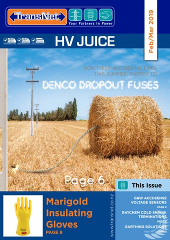
Feb/Mar 2019
HV JUICE
DON'T RISK ACCIDENTAL FIRES THIS SUMMER. SWITCH TO
Page 6
PAGE 8
www.transnet.co.nz
Marigold Insulating Gloves
This Issue G&W ACCUSENSE VOLTAGE SENSORS PAGE 2
RAYCHEM COLD SHRINK TERMINATIONS PAGE 4
EARTHING SOLUTIONS PAGE 7
G&W ACCUSENSE® VOLTAGE SENSORS G&W’s Accusense® Voltage Sensors are a meteringclass voltage-sensing solution that enables users to collect critical voltage data needed for optimizing grid power delivery and reliability.
new
Accusense voltage-sensing technology is an alternative to traditional metering class voltage-transformers and is available as a stand-alone voltage metering system or with the Viper-ST as a site-ready solution.
FEATURES/BENEFITS • Metering class, 0.5% voltage-sensing accuracy –– Key component in optimizing power delivery and reliability • No Ratio Correction Factors (RCFs) required • One ratio for all voltages (5000:1) • Eliminates the need for voltage transformers used in high-accuracy voltage measurement applications –– Easy to install, lightweight –– Safe, Low Energy Analog (LEA) output –– Cannot back-feed, output isolated from primary • Phase Measurement, better than ±0.2º • Site-Ready Solution –– Factory installed and tested • Compact • Capacitive voltage-sensing technology –– Maintains accuracy and phase angle performance with long cable lengths (advantage over resistive divider technology) • Silicone rubber insulation construction
–– Field-proven material with excellent hydrophobic properties • Compatible with SEL-651R and 42-pin control cable
APPLICATIONS • Intelligent metering Viper reclosers –– High accuracy power quality measurement • Retrofit to reclosers installed in the field –– Fault location, isolation, service restoration (FLISR) • Stand-alone, high accuracy voltage metering • Meter at feeder, capacitor banks, end of line, and interties • Conservation Voltage Reduction (CVR) & Volt-VAR Optimization (VVO) • Volt-VAR Compensation (VVC) • Power Quality • Sync Check
38kV Accusense® Voltage Sensor
Accusense® Voltage Metering System (independent mount)
Ph 0800 442 182 +64 9 274 3340
Viper-ST paired with Accusense® Voltage Sensors
Specifications VOLTAGE RATING 15/27KV 38KV WITHSTAND TEST VOLTAGE 60KV, 1 MIN 70KV, 1 MIN BASIC IMPULSE LEVEL (BIL) 170KV 225KV WEIGHT 4LB 9LB 0.5 CLASS (±0.5% MAGNITUDE, ±0.344° ACCURACY CLASS PHASE) RATIO 5000:1 (V:V) OUTPUT LOW ENERGY ANALOG (LEA), 8V AC (MAX) TEMPERATURE RANGE -40°C TO +65°C STANDARD IEC 60044-7:1999, IEEE C37.92-2005
sales@transnet.co.nz
www.transnet.co.nz
STAYING SAFE Ritz Temporary Earth Sets offer protection to Linemen from accidental livening and offer a direct path to earth for any current that should accidently enter the work site.The fully insulated hotsticks are permanently attached to the clamps, giving an even greater visual reference of the earthed zone. Easy to install, simply position the clamp and tighten onto the conductor using the attached hotstick. These earths are a well known and extensively used design here in New Zealand.
ritz temporary earth sets Features
• Attached earth stick • Reflector at the top of each stick for night time visual check • Flexible Copper conductor with clear sheath for ease of visual inspections • Factory test report supplied with every set • Unique serial number for traceability • Inspected & tested to IEC 61230 standard
Set includes:
Cat No.
Description
CAR/ST-NZ-HG14880 CAR/ST-NZ-HG14880-5 TN11-33KV/SET
35MM², 1 PIECE STICKS 50MM², 1 PIECE STICKS 35MM², 2 PIECE STICKS
TN277NZHP HIGH VOLTAGE DETECTOR
tnpd proving DEvice FOR TESTING NON-CONTACT VOLTAGE DETECTORS
Features • • • •
• • •
• •
Non-contact detection of live voltage Detect residual & induced voltages Sturdy tough case Meets requirements of EEA Technical Guide: Portable Equipment for Work On or Near Conductors Meets requirements of ASTM F1796-09, IEC 61243-1 & IEC 61243-2 Use for checking grounding equipment 2 ranges for selection: LOW : 50V~1.5kV HIGH : 1.5kV~132kV Circuit test function Low power consumption CAT NO. TN277NZHP Operating Temp Dimensions Weight (incl. battery) Power Source Safety Standards Accessories
0°C ~50°C 318 (L) x 75 (W) x 71 (D)mm Approx. 277g 9V (6LF22) x 1 Alkaline battery EN 61326- 1 EN 61000-4-2 EN 61000-4-3 Instruction Manual, Carry Case, Battery
Ph 0800 442 182 +64 9 274 3340
• 3x 3m leads attached to fully insulated line clamp hotsticks • 1x 9m lead from cluster to ground with ground clamp • 1x 1m lead from cluster to pole with ground clamp to bond pole metal work • 1x heavy duty storage bag • 1x 1m earth stake • 1x Acrylic cluster cover for easy fast inspection of connections
As per the EEA Guide To Portable Equipment For Work On Or Near Conductors, Voltage Detection Devices (VDDs) shall be supplied with or incorporate a proving device. The TNPD is the perfect solution, giving peace of mind that worker safety is taken care of.
Features • 150W Can-Sized Power Inverter • Plugs into the cigarette lighter socket and outputs 230 V AC • Able to power a variety of 230 V AC equipment from a battery chargers to laptop power supplies • Powered by cigarette lighter socket adaptor • USB port with 2.1A output • Electrical isolation prevents sudden mains voltage at cigarette lighter socket • Modified sine wave • Input: 12 V DC, USB Output: 5 V DC, 2.1 A • Dimensions: 165(L) x 60(Dia.) mm
sales@transnet.co.nz
CAT NO. TNPD
www.transnet.co.nz
WHY RAYCHEM FOR POLYMERIC INSULATED CABLES MXSU FEATURES • Can be designed to network specific requirements • Screen termination products can be included according to network specifications and cable fault current ratings if required • Mechanical connectors for conductor and wire shield are supplied with the kit • Kits are widely range taking and cover most conductor constructions including tolerances • No crimping tools or tool maintenance required • Short and space saving design for installation • Improves installation reliability • Unlimited shelf life, reduces cost • Avoids bulky waste and costly waste disposal • Exceeds international performance standards including CENELEC HD 629 or IEC 60502-4 for joints
mxsu jointing system for polymeric insulated cables CSTI/O cold shrink terminations are made from a high performance, liquid silicone material specially formulated for excellent tracking and split resistance. The extra-long silicone stress cone is integrated within the termination to ensure correct positioning. All key components are pre-expanded on one holdout system, allowing neat installation in compact environment on the prepared cable. CSTI/O terminations are designed to cover a wide range of applications and accommodate the variety of cable and conductor types used in the networks. Range-taking mechanical lugs ensuring reliable installation.
Ph 0800 442 182 +64 9 274 3340
SHEAR BOLT CONNECTORS All joint kits incorporate a Raychem screw connector with shear head bolts to ensure a reliable preengineered electrical connection. The pre-set shear torque of the bolts ensures that the correct contact pressure is always achieved. The specially designed contact surface on the inside of the connector breaks up any conductor oxide layer and ensures reliable service over the entire life time of the joint. The connectors have been tested in accordance with IEC 61238-1 class A.
BSM TYPE CONNECTORS FOR ALU & CU CONDUCTORS • Pre-set shear torque provides safe & reliable installation • Removable half shell insert provides core centering • Tin-plated and greased contact surface for corrosion protection • Shorter length compared to compression connectors • Excellent tensile performance due to special bolt tip design
CSTI/O FEATURES • Easy to install spiral holdout • Integrated sealing mastic • Outstanding weathering, UV and Ozone Resistance • Chemically resistant • Resistant to fungi • Excellent electrical properties, including good tracking resistance and high dielectric strength • Electrical stress control of the screen cut area using integrated conductive geometrical stress cones • Hydrophobic (waterrepellent) • Non-flammable • Self-extinguishing • Retains performance over wide temperature range ±45 to +150°C • Excellent resistance to
sales@transnet.co.nz
splitting and permanent set • Mechanical shear bolt lug and compression lug to IEC 61238-1 can be supplied • CENELEC HD 629.1.S2, requirements which include IEC, BS, VDE and other international specifications, IEEE-48 • Manufacturing site ISO 9001 & ISO 14001 qualified
www.transnet.co.nz
SHIELD CONTINUITY Typical shield wire cross sections up to 35mm² can easily be connected with the mechanical connector supplied in the kit. Positioned at the oversheath cut back, the connection provides a smooth profile and resists mechanical damage. There is no need for a crimping tool and its maintenance. Two shear bolts provide the required contact force in order to ensure safe installation and reliable performance during load cycling in service as well as during short circuit conditions. An additional layer of copper mesh is applied around the joint to provide satisfactory shielding and protection.
BENEFITS • Pre-expanded termination body with integrated stress control deflector and sealing mastic • Single piece silicone termination body with optimal mechanical expansion ratio allows a wide application range • The extra-long silicone stress cone is integrated with the termination and reduces positioning • Moisture sealing at the lug is integrated – no additional sealing tapes • Well-known and easy-to-install holdout system, rip cord pulling direction towards the lug not the bottom of the termination • Easy to install in tight switchgear compartments • Accommodates mechanical shear bolt lug (included in kit) compression lug
ELECTRICAL STRESS CONTROL The stress control tubing at each cable end in combination with the yellow stress grading mastic at the screen cut provide a precisely defined impedance characteristic which smoothes the electrical field. For ease of installation, a stress control patch is applied around the mechanical connector to provide a similar function.
ROBUST OUTER SEALING AND PROTECTION Modern cable laying techniques require a robust oversheath replacement capable of withstanding high mechanical stresses during conventional cable laying as well as mechanical impact occurring during the entire cable life time. The thickwall heat-shrinkable tubing is internally coated with a hot melt adhesive to ensure an effective moisture seal and corrosion protection for the joint. When installed, the joints provide the similar level of protection and thickness as modern cables with PE oversheath. All voltage sheath testing commonly used today after cable laying or as control test methods have easily been passed.
csti/csto cold shrink terminations for polymeric insulated cables Cat No.
Size Voltage Number Range (kV) of Cores Al or Cu (mm²)
Indoor
Outdoor
CSTI-3122-ML-1-13
CSTO-3122-ML-1-13
CSTI-3132-ML-4-13
CSTO-3132-ML-4-13
CSTI-3142-ML-6-17
CSTO-3142-ML-6-17
CSTI-3152-ML-7-17
CSTO-3152-ML-7-17
500–630
CSTI-5122-ML-1-13
CSTO-5122-ML-1-13
25–95
CSTI-5132-ML-4-13
CSTO-5132-ML-4-13
CSTI-5142-ML-6-17
CSTO-5142-ML-6-17
CSTI-5152-ML-7-17
CSTO-5152-ML-7-17
CSTI-6122-ML-1-13
CSTO-6122-ML-1-13
50–70
CSTI-6132-ML-4-13
CSTO-6132-ML-4-13
95–150
CSTI-6142-ML-6-17
CSTO-6142-ML-6-17
CSTI-6152-ML-7-17
CSTO-6152-ML-7-17
CSTI-6162-ML-8-21
CSTO-6162-ML-8-21
A l l S p e c i a l s a n d P ro d u c t s fe a t u re d i n T R A N S N E T J U I C E a re ava i l a b l e f ro m a l l g o o d e l e c t r i c a l w h o l e s a l e r s .
25–95 11
22
1
1
95–240 300–400
95–240 300–400 500–630
33
1
185–400 500–630 800– 1000
CURRENT-LIMITING DROPOUT FUSES BY DENCO
WHY DO YOU NEED A DENCO DROPOUT FUSE?
PREVENT ACCIDENTAL FIRES
• No Sparks or Molten Fragments • No Release of Hot Gases • Replace cutout expulsion fuse-links • Current Limiting • High Rupture Capacity • Low Voltage Arc • Low Watt Loss • Pure Silver element protected by epoxy resin coated fibreglass tube • Fuse cavity filled with carefully compacted granulated quartz silica • Cut Off Time U.R.
SUITABLE FOR: • Substation networks • Aerial urban and rural distribution power lines PARTS EXPELLED FROM FUSE CUTOUTS FAULT LEVEL 3,400 Amperes
8,000 Amperes
DENCO
STANDARD
500 Amperes
Ph 0800 442 182 +64 9 274 3340
sales@transnet.co.nz
www.transnet.co.nz
ERICO EARTHING SOLUTIONS CADWELD PLUS ONE SHOTproduces a permanent exothermic connection to a ground rod that won't loosen, corrode or increase in resistance for the life of the installation. The convenient single-use package makes the connection without a mold or starting material, and the refractory ceramic body is more durable than conventional ceramic and resists breaking. Ideal for electrical transmission and distribution, telecommunications and cable television applications.
FEATURES • Durable disposable ceramic body eliminates • Six foot the graphite mold and frame control unit lead gives • Permanent connection won't loosen or corrode increased • Electronic Control Unit #PLUSCU (sold flexibility in hard to reach areas separately) ensures no starting material is • NEC Compliant and UL Listed required and easy ignition
ERICO GEM is a low-resistance, non-corrosive, carbon-based superior
Will never conductive material that improves grounding effectiveness, especially in areas of leach into poor conductivity like rocky ground, mountain tops and sandy soil. GEM is also the surrounding answer in situations where ground rods can’t be driven or where limited land area soil or ground makes adequate grounding difficult with conventional methods. water • Non-corrosive FEATURES • Fully sets in 3 days, fully cures in 28 days • Dramatically reduces earth resistance and • Reduces vandalism and theft since conductors impedance measurements are hard to remove from concrete • Maintains constant resistance for the life of • Easy-to-handle 25 lb (11.3 kg) bags the system once in its set form • Requires one person to install • Performs in all soil conditions even during dry spells • Exceeds IEC 62561-7
Why ERICO copper bonded earth rods?
ERICO's unique manufacturing process includes drawing the steel rod to size before the copper bonding process begins, resulting in a straighter, harder steel core. They use a continuous electroplating process over the steel core resulting in a permanent molecular bond which will not slip or tear when drive, nor crack when bent, that provides decades of reliable performance.
liant t
p CARBON STEEL CORE & TIP*: • Greater Tensile Strength 007 000:2 /nzs 3 s a • Deep driving capability
*ERICO copper-bonded rods
eq
sales@transnet.co.nz
nt
s
o
Ph 0800 442 182 +64 9 274 3340
ERICO COPPER-BONDED COATING: • Permanent molecular bond • Low resistance performance • High fault current capacity (IEEE® Std 80) • Will not slip or tear when driven • Will not crack if rod is bent • Copper coating may vary to meet required standards • 10 mil (254 micron) minimum coating on rods listed to UL®467
r
• 99.9% pure electrolytic copper coating • Nickel-sealed high strength steel core • ERICO® name, length, diameter and part number is roll-stamped within 12" (304,8 mm) of chamfered end • UL logo and control number where applicable stamped on each rod for easy inspection after installation • All ERICO® rods are made to meticulous standards and exceed the requirements outlined in AS/NZS 3000:2007 for minimum surface treatment thickness.
com
FEATURES
uirem
e
www.transnet.co.nz
GIVE YOURSELF THE UPPER HAND Marigold Rubber Insulating Gloves Features & Benefits
TransNet New Zealand Ltd Auckland 78 Cryers Road East Tamaki Auckland NEW ZEALAND Ph 0800 442 182 Fax 0800 442 183 PO Box 39 383 Howick, Auckland Wellington 10 Petone Ave Petone Wellington NEW ZEALAND Ph 04 576 2530 Fax 04 576 0040 PO Box 39 383 Howick, Auckland NEW ZEALAND sales@transnet.co.nz TransNet Tonga Ma’ufanga Small Industries Ma’ufanga TONGA Ph +67 627 939 Fax +67 627 976 PO Box 2932 Nuku'alofa TONGA transnet@kalianet.to
• Pure latex gloves manufactured under ISO 9001 & ISO 14001 • Dual layer construction • Certified to EN 60903 • Also available in ASTM D120 • Ergonomically shaped • Excellent strength & durability • Supreme feel & flexibility • Manufactured without the use of solvents & hazardous chemicals utilising a proprietary aqueous dipping process • Low temperature resistant
How to Measure Measure around your hand, above the V of the thumb. This gives you the circumference
• Acid resistant • Ozone resistant • Custom designed outer protector gloves also available • Chlorinated for easy donning & duffing • Comprehensive range of classes, colours, lengths & sizes, including half sizes • Various cuff styles available including straight, contour & bell • Arc Flash certified Max Class MAX USE Use* MAX 500 VUSE AC ColourCLASS Voltage 500 V AC MAX USE 00 MAX 500 VUSE AC AC/DC CLASS 1 T YP E00 MAX USE
ANSI ASTM D120 EN60903 Illustrative Labelling ANSI ASTM D120 MAX USE 500 VEN60903 AC ANSI D120 MAX USE 500 VEN60903 AC TYPEASTM 1 USE CLASS 00 ANSI ASTM D120 EN60903 MAX 500 V AC 00 10 TYPE 1 CLASS ANSI ASTM D120 MAX USE 500 VEN60903 AC 10 TYPEASTM 1 USE MAX 500CLASS VEN60903 AC 00 ANSI D120 10 TYPE 1 CLASS 00 10 MAX USE 500CLASS V AC 00 P E 1500/ TYPE 1 00 T Y PUSE E00 MAX ANSI D120CLASS EN60903 BEIGE CLASS 750 TYPEASTM 1 10 00 T Y PVUSE MAX 1,000 ANSI ASTM D120 EAC1 10 MAX USE 1,000 EN60903 V AC 1,000 AC MAX V USE ANSI ASTM D120 EN60903 CLASS 0 MAX USE 1,000 V AC MAX 1,000 AC CLASS 0 TYPEMAX 1 USE10 ANSI ASTM D120 CLASS T Y PVUSE 1,000 EN60903 V AC EAC011 MAX 1,000 CLASS 0 TYPEMAX 1 USE10 ANSI ASTM D120 EN60903 T Y PVUSE CLASS 0 1,000 V AC E 1,000 AC CLASS 0 TYPEMAX 1 USE10 MAX CLASS 01 T Y PVUSE 1,000 EN60903 V AC ANSI ASTM D120 0 1,000/ CLASS 0 TYPEMAX 1 USE10 1,000 CLASS T Y PVEEAC01 1,000 V AC TYPE 1 10 CLASS 0 RED CLASS T Y PUSE E 011,500 MAX ANSI ASTM D120 EN60903 CLASS 0 TYPEASTM 1 10 T Y PVUSE MAX 7,500 EAC1 ANSI D120 EN60903 MAX USE 7,500 V AC 7,500 V AC MAX USE CLASS 1 ANSI ASTM D120 7,500 EN60903 V AC MAX 7,500 AC TYPEMAX 1 USE CLASS 1 CLASS T Y PVUSE ANSI ASTM D120 7,500 EN60903 V AC EAC111 10 MAX 7,500 TYPEMAX 1 USE CLASS 1 T Y PVUSE ANSI ASTM D120 CLASS 1 1 7,500/ MAX USE 7,500 EN60903 V AC EAC 10 7,500 TYPEMAX 1 USE CLASS 1 MAX 11 T Y PVUSE 7,500 EN60903 V AC ANSI ASTM D120 WHITE CLASS 11,250 TYPEMAX 1 USE10 CLASS 1 7,500 CLASS 11 T Y PVEEAC 10 7,500 V AC TYPE 1 CLASS 1 1 T Y CLASS 1 E 10 MAXPUSE ANSI ASTM D120 EN60903 TYPE 1 CLASS 1 1 T MAX USE 1,7000 Y PVEAC ANSIMAX ASTM D120 EN60903 10 USE 17,000 V AC 1,7000 V AC MAX USE2 ANSI ASTM CLASS MAX USED120 17,000EN60903 V AC MAX USE 1,7000 V AC TYPE 1 USE10 CLASS 2 ANSI ASTM D120 EN60903 CLASS 21 T Y PUSE 2 17,000/ MAX 17,000 V AC E MAX 1,7000 V AC TYPE 1 CLASS ANSIMAX ASTM D120 T Y P E 21 CLASS 17,000EN60903 V AC 2 10 V AC YELLOW1,7000 25,500 TYPE 1 USE CLASS MAX CLASS 21 T Y PUSE MAX 17,000EN60903 V AC 2 ANSI ASTM D120 10 TYPE 1 USE 1,7000 CLASS 21 T Y PVEEAC MAX USE10 17,000CLASS V AC 2 TYPE 1 CLASS 2 1 T Y PUSE CLASS E2 MAX ANSI D120 EN60903 TYPEASTM 1 10 CLASS 2 1 T Y PUSE MAX 26,500 VEAC ANSI ASTM D120 MAX USE10 26,500EN60903 V AC 26,500 V AC MAX USE CLASS 3 ANSI ASTM D120 EN60903 MAX USE 26,500 V AC 3 26,500/ MAX 26,500 V AC TYPE 1 USE10 CLASS CLASS 31 T Y PUSE ANSI ASTM D120 MAX 26,500EN60903 V AC 3 MAX VEAC TYPE 1 USE10 CLASS GREEN 26,500 39,750 T Y PUSE ANSI ASTM D120 CLASS 31 MAX 26,500EN60903 V AC 3 26,500 VEAC MAX TYPE 1 USE10 CLASS CLASS 31 T Y PUSE MAX 26,500EN60903 V AC 3 ANSI ASTM D120 TYPE 1 USE10 CLASS 3 26,500 CLASS 31 T Y PVEEAC MAX 26,500 V AC 3 TYPE 1 10 CLASS T Y PUSE CLASS E 31 MAX ANSI ASTM D120 EN60903 TYPEASTM 1 10 CLASS 3 1 T Y PUSE MAX 36,000 VEAC ANSI D120 EN60903 MAX USE 36,000 V AC 4 36,000 V36,000/ AC MAX USE ANSI ASTM D120 EN60903 MAX USE 36,000 V AC CLASS 4 MAX 36,000 V AC TYPE 1 USE10 CLASS ORANGE 54,000 ANSI ASTM D120 CLASS 41 T Y PUSE MAX 36,000EN60903 V AC 4 MAX TYPE 1 USE10 CLASS 36,000 VEAC ANSI ASTM D120 T Y PUSE CLASS 41 MAX 36,000EN60903 V AC 4 36,000 VEAC TYPE 1 USE10 CLASS MAX MAX 36,000EN60903 V AC 4 CLASS 41 T Y PUSE ANSI ASTM D120 EAC TYPE 1 CLASS 36,000 V CLASS 4 1 T MAX 36,000 V AC 4 InsulatingT YGloves and Sleeves must have a colour 10 PE TYPE 1 USE CLASS 4 Y P E 41 CLASS 10 coded label meet appropriate ASTM Specifications. TYPE 1 CLASS 4 1 T Y P to E 10 500 V AC 1 T YP CLASS E00 500 VUSE AC MAX 1 CLASS T YP E00 500 CLASS 00 1 T Y V AC
*Max Usage Voltage when worn with leather protectors
How To Order Example = RIG-4 -18-YB-C-10H A B C D E
F
A - Glove Type: RIG (Rubber Insulating Glove) B - Class: 00/0/1/2/3/4 C - Length: 11/14/16/18 (inches) D - Colour: R/Y/YB/BY (Red, Yellow, Yellow under Black, Black under Yellow) E - Cuff: S/C/B (Straight, Contour, Bell) F - Size: 7/8/8H/9/9H/10/10H/11 (H= ½ sizes) TransNet NZ Ltd has made every reasonable effort to ensure the accuracy of this information and it is to the best of our knowledge correct and reliable. Under no circumstances does this constitute an assurance of any particular quality or performance and users should independently evaluate the suitability of products for their desired application. All information in this publication including pricing, drawings, illustrations, images and graphic designs are reflections of our current understanding. TransNet NZ Ltd reserves the right to make any adjustment to this information at any time. Our liability for the products outlined in this publication is set forth in our standard terms and conditions of trade. In case of any potential ambiguities or questions, please contact us for clarification.