THOMAS MASINO , RA, NCARB architectural design portfolio select professional and academic work
PROFESSIONAL
SELECT PHOTOGRAPHY R2L:Architects | Aug 2018 - present Washington, DC R2L:Architects | Oct 2017 - Aug 2018 Charlottesville, VA Barnes Vanze Architects | Jun 2017 - Oct 2017 Bethesda, MD CSX EAST - AC HOTEL CAPITOL HILL & ILLUME APARTMENTS WEST 2ND PRIVATE RESIDENCE TABLE OF CONTENTS 6 26 36 42 100 48 Clemson University - Barcelona Architecture Center | Spring 2016 Toni Montes and Miguel Roldan SHIFT AND SUBVERT 58 Clemson University | Fall 2015 Ufuk Ersoy, David Franco, and Ulrike Heine CLEMSON BOAT HOUSE 72 ACADEMIC WORK University of Maryland | Fall 2013 Luis Quiros CO-LAB 84 University of Maryland | Spring 2014 Michael Ezban ENVISION SALISBURY 90 DIGITAL CRAFT - SCRIBBLED BRICK
WORK
PROFESSIONAL WORK
CSX EAST - AC HOTEL CAPITOL HILL & ILLUME APARTMENTS
Washington, DC
R2L:Architects role: Primary Staff programs used: Revit 2018, Photoshop, and Illustrator
I started on this project relatively early on, right after project start-up and initial massing presentations to the client. The overall project consists of three buildings sited right on the highway in Navy Yard, with great views of the Capitol, on top of two levels of below-grade parking. The program consists of a hotel, a restaurant, two floors of office space, apartments, and associated amenity spaces. Overall, the project has a budget of approximately $260 million with 225 guestrooms and 756 apartment units.
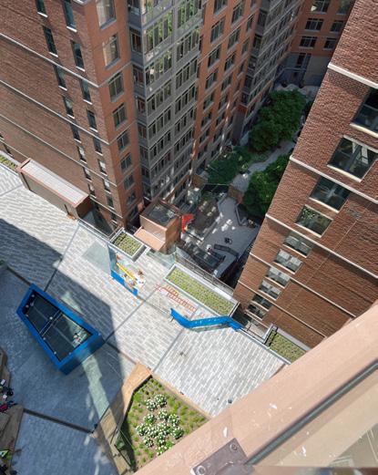
The site was a challenge to work with due to topography and underground pipes and sewers that could not be built over. The overall form of the three buildings was driven by these underground factors and their associated easements, the highway easement, and creating green veins that extend from the properties to the south through the site. The project has complex connections to existing buildings and between the buildings themselves. The hotel building interacts with an existing building to the south (ORE 82) twice, once on the ground floor through the loading dock and once on the eleventh floor through a bridge. The below-grade parking garage interacts with the underground parking to the south (under 70 & 100 Capitol Yards) through a two different door and stair penetrations in the foundation wall. The central courtyard interacts with the courtyard of 100 Capitol Yards through an elevator tower and open-air stair. The hotel also connects to the one of the office floors through a conditioned glass bridge, that same office floor connects to the third building through a similar glass bridge, and the two residential roof amenity spaces are connected via a glass, open-air, skybridge. The purpose of connecting to ORE 82 was to take advantage of zoning regulations. Since we made meaningful connections to ORE 82 and it was built under prior zoning regulations, we gained two additional floors of apartments in Building 3.
While the majority of my time on this project was devoted to the hotel, Building 1, I have also worked on parts of the project relating to the residential scope, including the bridges and the connection to 100 Capitol Yards. In December 2020 the project manager went on an extended sabbatical and I assumed their role and responsibilities. I became the first person the construction team called with questions and was also responsible for compiling permit amendment submissions and returning residential CA items. I have visited the site almost every week and have watched the project from excavation to the present.
6
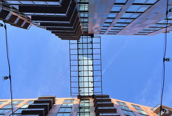
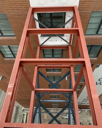
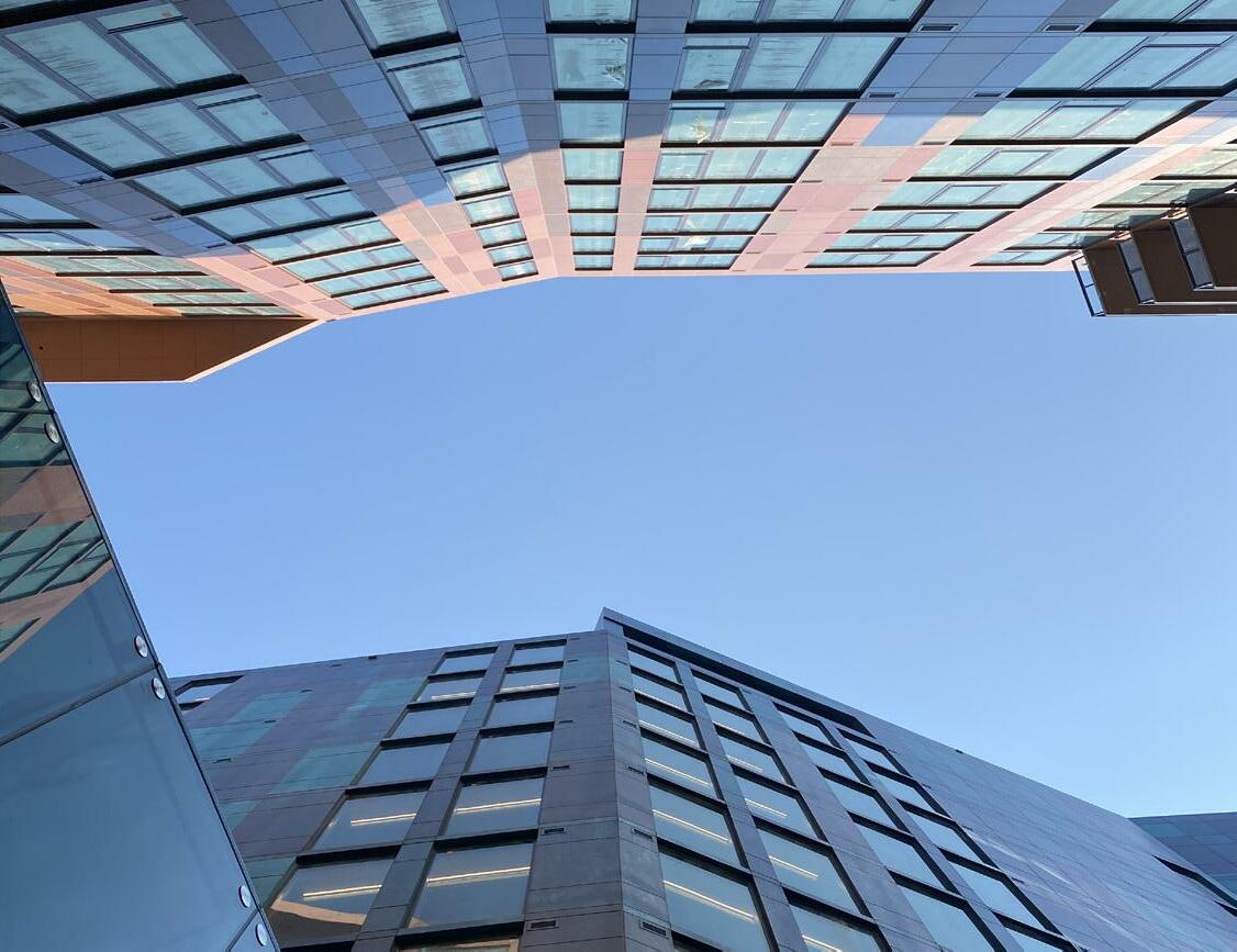 Photograph taken between Building 2 (upper, apartments and office) and Building 1 (lower, hotel) looking up (by self).
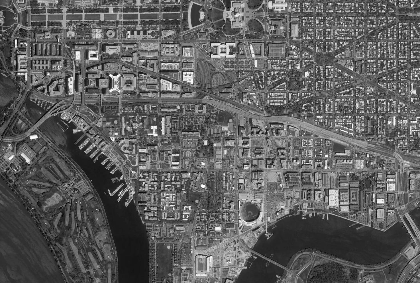
SITE I STREET SE I-395 / I-695 FIRST STREET SE 14TH STREET SW NEW JERSEY AVE SE ANACOSTIA RIVER WASHINGTON CHANNEL POTOMAC RIVER SOUTH CAPITOL STREET SW INDEPENDENCE AVE NATIONAL MALL AMTRAK PENNSYLVANIAAVESE CAPITOL BUILDING UNITED STATES SUPREME COURT LIBRARY OF CONGRESS presentation drawing vicinity plan (initial drawing by others, edits by self)
SITE & EXISTING CONDITIONS


The site is bounded to the north by I-695, to the east by New Jersey Avenue SE, to the west by an adjacent lot, and to the south by three existing buildings (70 Capitol Yards, 100 Capitol Yards, and ORE 82 Eye) and I Street SE.
An existing sewer runs under the northeast corner of the site and existing, unused pipes belonging to the Architect of the Capitol run north-south through the middle of the site.
EASEMENTS & RESTRICTIONS












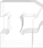
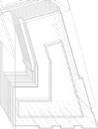























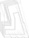










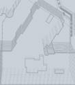
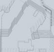




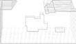
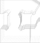








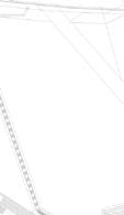
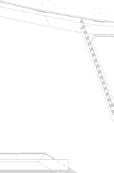


The highway required a fifteen-foot restriction and an additional twenty-foot setback, meaning the furthest north we could build was thirty-fivefeet from the highway. Additionally, the existing sewer required an eight-foot setback.


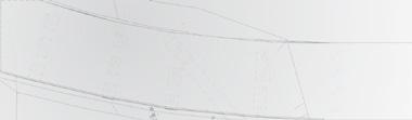


It was unknown what degree we could build over the pipes belonging to the Architect of the Capitol, so we assumed the worst-case scenario and did not plan any groud floor space over them.


INTERNAL STREETS
The new streets into the site and down to the parking levels are extensions of existings streets: the east site entrance is an extension of H Street SE and the south site entrance is an extension of First Street SE.
These roads converge and continue along the north end of the site, occupying a portion of the thiry-five-foot zone from the highway that we could not build in.
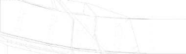

NEW JERSEY AVENUE SE I STREET SE A UE SE YARDS 100CAPITOL YARDS ORE 82 -69 (SO HE ST FREEWAY) HSTREETSE F I R S T STREET S E H STREET SE
project narrative diagrams (by self) 9
BUILDING MASSING
Taking into account the restrictions and internal roads, three buildings were sited to navigate these challenging conditions. The buildings are oriented in a roughly north-south direction in an attempt to create porosity and views through the site from the buildings to the south.
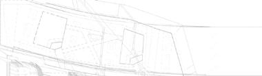
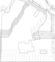
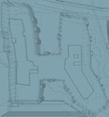
Based on current zoning, the buildings had a maximum height of 110’, resulting in Building 1 (hotel, eastmost) having 225 keys across nine floors (eleven floors total) and Buildings 2 & 3 (apartments, center and westmost) having 240 and 440 units, respectively, across ten floors (twelve floors total).
BRIDGES & CONNECTIONS
After the intial building massing was determined, we studied connecting to the existing buildings to the south. Doing so allowed for a number of benefits, including the use of excess parking spaces in 70 and 100 Capitol Yards by Illume residents and the use of Illume’s brand-new amenities by Capitol Yards residents.
But most importantly, by connecting to ORE 82 Eye, we were grandfathered into the zoning regulations that ORE 82 Eye was permitted under, allowing us to build to a maximum height of 130’.
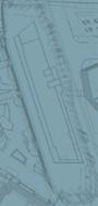












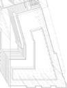











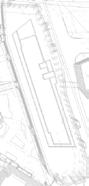
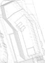



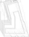










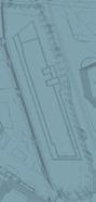
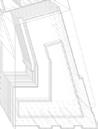





There are four bridges, a ground floor connection between loading docks, an open-air courtyard connection, and two connections between garages.
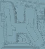
TALLER BUILDING MASSING & GREEN SPACE






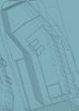
With the increased building height, we added one more floor to Building 2, replaced the lowest two floors of units with office space, and increased the floor-to-floor height, resulting in 214 units across nine floors (thirteen floors total). Building 3 gained two floors, resulting in 542 units across thirteen floors (fourteen floors total)
A central courtyard full of planters and vegetation occupies the space between Buildings 2 & 3, extending the green space at Capitol Yards and creating these green veins through the block. The south site entry is also framed by terraced planters and trees.
We created a pocket park in the space north of Building 1 over top of the existing sewer and located a dog park under the highway.
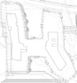
project narrative diagrams
BUILDINGS 2 & 3 - ILLUME APARTMENTS
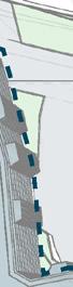
259,000 SQFT & 489,700 SQFT with 147,000 SQFT of below-grade parking | LEED Gold
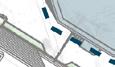
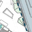
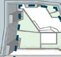
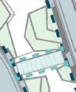
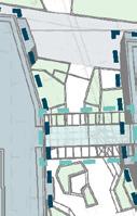

involvement: construction administration through project closeout ; also responsible for coordinating permit submissions for various amendments (B2 roof, B3 FCR, B2 office bathrooms, and pools) with our expediter (overall building permit coordinated by previous project manager).
approximate time of involvement: Dec 2020 - Dec 2022

note, only the second and third floors of Building 2 were not delivered by the design and construction team; these office floors were completed by another architect and JMA.
involvement & scope description diagram
BUILDING 1 - AC HOTEL CAPITOL HILL NAVY YARD
134,600 SQFT | LEED Certified
involvement: massing though project closeout
approximate time of involvement: Aug 2018 - July 2022
note, only the ground floor retail space was delievered as a warm, dark shell, to be outfitted by a future tenant.
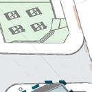
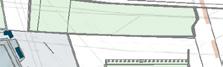


BRIDGES 2, 3, and 4
involvement: design development through closeout .
approximate time of involvement: May 2020 - Sep 2022
PROJECT TEAM
structural SK&A | residential mechanical, residential plumbing, and hotel plumbing BOWMAN (KTA)


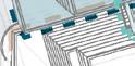

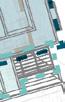












| electrical PDI | hotel mechanical
EDG2 | civil WILES MENSCH |


envelope SGH | hotel lighting WPF
















|
hotel interior design DLR GROUP |












restaurant interior design
ELLIS ADAMS GROUP | accessibility


SKARZENSKI | residential hardware







ECSI | hotel hardware PARAGON
| acoustics ADC | code JENSEN




HUGHES | leed SBP


contractor | JMA



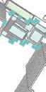
CAPITOL YARDS CONNECTION
involvement: design development through closeout , also responsible for coordinating permit submission with our permit expediter.



approximate time of involvement: Aug 2020 - Sep 2022
BRIDGE 1
involvement: design intent through closeout , also responsible for coordinating the unit renovation permit submission in ORE 82 with our permit expediter.
approximate time of involvement: Dec 2018 - Jan 2022

11
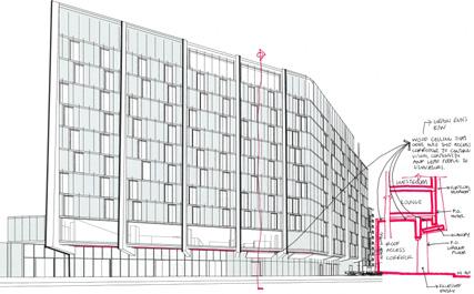
process sketches
facade development (linework export and markups on trace by self)
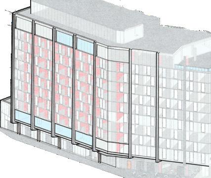
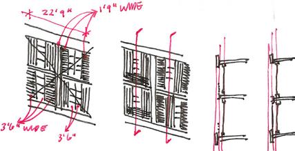
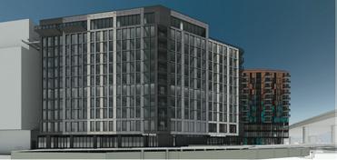
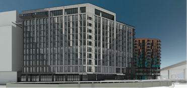
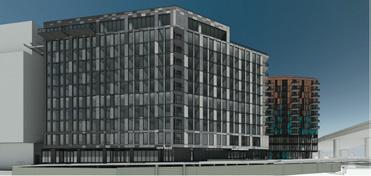
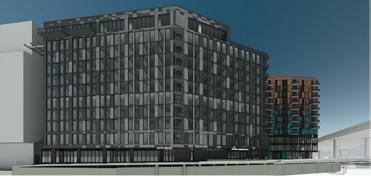
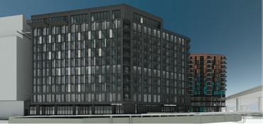
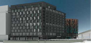
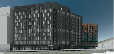
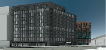
process views
view of the hotel from New Jersey Avenue used to study the introduction of other colors and patterns into the above right image (modeling, image export, and image manipulation by self)
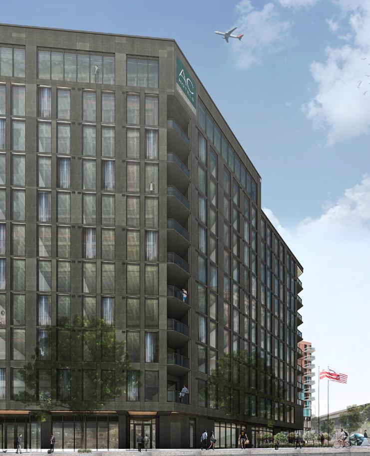 presentation drawing
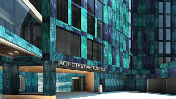
view of the east facade and restaurant entrance (modeling, raw render, linework export, and postproduction by self)
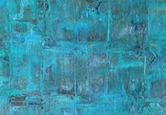
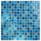
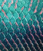
inspiration images
metal panel option studies
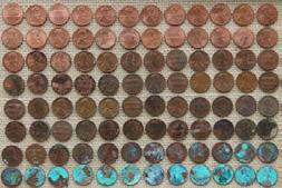
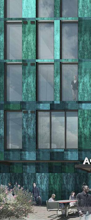
used to study less expensive, standard color options available from various manufacturers and the sealant color, compared to previous renderings (by self)
SHERWIN WILLIAMS FUNDAMENTAL NEUTRALS SERIES
SHERWIN WILLIAMS COLOR OPTIONS SERIES





























SHERWIN WILLIAMS ENERGETIC BRIGHTS SERIES
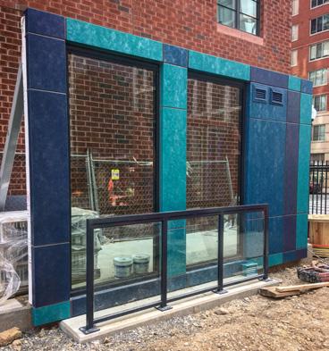
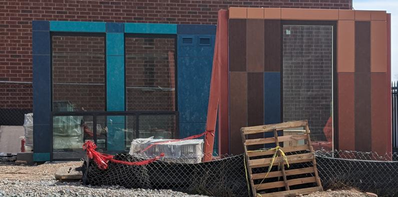
on-site mockup photographs
RENDERED IMAGE navy navy ultramarine blue naval indigo blue blood dark patina dark patina bakos blue rainstorm loyal blue pulsating blue cerulean cerulean bellereve blue refuge oceanside cote d’azur patina patina strong sage still water really teal tempo teal emerald emerald fairview green underseas green bay turquish granite grey PURE AND FREEFORM SAMPLES VITRABOND
ACM COLOR 5 ACM COLOR 4 ACM COLOR 3 ACM COLOR 2 ACM COLOR 1
13
left photo: hotel facade (left, background) and residential facade (right, foreground) mockup right photo: closer view of only the hotel facade mockup (02/28/20, by self)
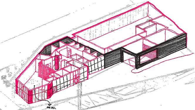
process sketch
ground floor axonometric (linework export and markups on trace by self)
construction documents
ground floor plan
(initial model, sheet set-up and major model / drawing edits by self)
FE FEC AH331 AH311 AH310 63 HP 62 61 60 HN HM HL HK HJ HI HE HF HG AH331 AH310 AH312 AH312 AH325 AH345 AH345 AH330 AH330 10 AH315 AH315 2 AH315 AH315 5 AH315 AH315 AH315 6 AH315 14 11 AH315 AH315 17 AH341 AH340 AH340 AH340 4-02920-20 20 2500 4-4 80389 52 -1 42 9/ 5224 22160 D 7B 3B 9C 7C 9C 9C 9C 9A FIRE CONTROL ROOM GH111 COPY LUGGAGE GH109 VESTIBULE GH101 ELEVATOR LOBBY GH106 SERVICE VESTIBULE GH114 LOUNGE GH102 GH122 GH121 GH113B GH101 GH112 GH116A GH116B GH118A GH109 GH111 GH102B GH107 % N LOADING GH117-PE-02 -03 SE-04 SERVICE CORRIDOR GH115 LOADING VESTIBULE GH116 17 16 % EYE GROUND FLOOR DOOR 4-71 - 3 92 14 3 2- 1 2- 0 2- 161 223 4315 5 25 2- 8 3-5 4 - 0 40 21014 3B AH341 AH341 AH341 2 AH341 AH340 AH345 AH345 AH605 18 9C 3B 9A 9B 7B 271/49C AH341 TL120 STEP LIGHTS 20 21 1/4 - 12 GH108 AH340 AH770 1 AH273 AH271 22 AH603 AH860 AH860 AH861 AH861 6 AH861 AH860 6 GH120A GH120B AH272 GH105 AH860 L504 L503 AH332 AH711C 2 GH123 9C AH813 AH813 ASI 003H AH342 AH711C ASI 004H 2634 1-93B HSS0 AH342 AH342 AH342 7 AH342 8 AH342 AH315 20 AH315 19 26 GH120D 31 31 26 L602 2 1 33'-5 3/4" 35'-6" 11G 11L 11C 2-218 24 22 RFI 042 1B 9C 9B 4 RFI 0450 DOOR OPEN 4- 1 7-8 B/T MU 17-0 DOOROP NG AH861 RFI 050 (2) 32-GALLON CANS FORDISPOSAL 10 (2 YD) (2 YD) (2 YD) (2 YD) (2 YD) LEGEND GENERAL NOTES KEYNOTES 1. REFER TO A001 FOR ADDITIONAL NOTES, ABBREVIATIONS & SYMBOLS. 2. REFER TO AH700 SERIES SHEETS FOR PARTITION SCHEDULE, FIRE RESISTANCE RATED WALL TYPES, & FLOOR CEILING ASSEMBLIES. ALL INTERIOR DRYWALL PARTITIONS ARE TYPE-1 U.N.O. 3. REFER TO AH500 SERIES SHEETS FOR ACCESSIBILITY AND TYPICAL DEVICE MOUNTING REQUIREMENTS. 4. REFER TO AH500 SERIES FOR TYPICAL BATHROOM REQUIREMENTS, INCLUDING GRAB BAR SHOWER SEAT BLOCKING DIAGRAMS. 5. REFER TO AH500 SERIES FOR TYPICAL KITCHEN DETAILS. 6. REFER TO LANDSCAPE DRAWINGS FOR PLANTINGS AND PAVING DETAILS AT OUTDOOR AREAS. CROSS & DRAINAGE SLOPES AT PAVER & DECKING PEDESTRIAN SURFACES SHALL NOT EXCEED 2%. 7. WHERE WALLS OF DIFFERENT TYPES ARE SHOWN TO ALIGN IN PLAN, ALIGN FINISHED FACE OF WALLS. 8. AT INTERIOR DOORS, INSIDE FACE OF HINGE-SIDE JAMB SHALL BE 4" MINIMUM FROM FACE OF ADJACENT INTERSECTING PARTITION, U.N.O 9. AT INTERIOR DOORS INSTALLED IN MASONRY PARTITIONS, INSIDE FACE OF HINGE-SIDE JAMB SHALL BE 8" MINIMUM FROM FACE OF ADJACENT INTERSECTING PARTITION, U.N.O. 10. PROVIDE WATERPROOFING AT INTERIOR FACES FLOORS OF CMU ENCLOSED SHAFTS THAT ARE EXPOSED TO WEATHER. 11. SEE AH300 SERIES EXTERIOR ELEVATIONS AND AH700 SERIES WINDOW AND PANEL SCHEDULES FOR WINDOW & TERRACE DOOR TYPES, RAILINGS, AND EXTERIOR WALL CONDITIONS. 12. SEE IDH & INH SHEETS FOR INTERIOR FINISH, ACCESSORY AND APPLIANCE SCHEDULES. 13. SKIM COAT & PAINT ALL EXPOSED COLUMNS IN FINISHED INTERIOR SPACES. 14. EXPOSED COLUMNS AT EXTERIOR SPACES TO HAVE ACM METAL CLADDING, FINISH AS NOTED ON BUILDING ELEVATIONS. 15. PROVIDE CONCEALED FIRE-TREATED BLOCKING FOR PARTITION-MOUNTED EQUIPMENT, FIXTURES, MILLWORK, AND AT GRAB BAR SHOWER SEAT LOCATIONS WHERE REQUIRED. 16. ELEVATION OF DRAINS IN GARAGE, LOADING & TRASH ROOMS SHALL BE 4" BELOW FLOOR ELEVATION LISTED, TYP, U.N.O. 17. FURNITURE SHOWN FOR REFERENCE ONLY. 18. PROVIDE CONTINUOUS 8" CONCRETE CURBS AT BASE OF ALL WALLS ENCLOSING ANY ELECTRIC ROOMS IN GARAGE. 19. PROVIDE STRUCTURAL STEEL PROTECTION BARRIER FOR ALL MECHANICAL, ELECTRICAL, AND PLUMBING EQUIPMENT THAT MAY BE SUBJECTED TO VEHICULAR DAMAGE. STRUCTURAL STEEL BARRIERS SHALL BE CONSTRUCTED OF 2"x2" STEEL ANGLE AND PAINTED YELLOW 20. ALL STRUCTURAL STEEL AND MISCELLANEOUS METALS NDICATED ON ARCHITECTURAL DRAWINGS, BUT NOT SHOWN ON STRUCTURAL DRAWINGS, ARE TO BE DESIGNED AND ENGINEERED BY SUBCONTRACTOR/SUPPLIER/ FABRICATOR OF SYSTEM OF COMPONENTS WHICH THEY ARE SUPPORTING. CMU WALL CONCRETE COLUMNS SLOPED COLUMNS WOOD DECK FLOOR ROOF DRAINS, SEE PLUMBING PROPERTY LINE RECESSED FIRE EXTINGUISHER & CABINET BRACKET-MOUNTED FIRE EXTINGUISHER TRENCH DRAIN SANITARY DRAINS, SEE PLUMBING TYPE A DWELLING UNIT PER ANSI 117.1-2009 WALL TAG, SEE PARTITION SHEET 3 TRENCH DRAIN FLOOR-MOUNTED U-RACK BIKE PARKING B1 PRIMARY ENTRY B1 VEHICLE DROPOFF NOT USED NOT USED MECHANICAL EQUIPMENT PLATFORM AND SCREEN FIRE DEPARTMENT CONNECTION & TEST HEADER MOTORIZED LEAF NON-SMOKING SIGNAGE, SEE AH501 GARAGE EXHAUST SHAFT GARAGE INTAKE SHAFT GENERATOR EXHAUST SHAFT GENERATOR INTAKE SHAFT OFFICE LOBBY ENTRY DOOR OPERATOR BUTTONS RECESSED INTO FRAMING MARRIOTT AC HOTEL EXTERIOR SIGNAGE - MAIN ENTRANCE LOGO TRANSFER GIRDER, SEE STRUCTURAL MECHANICAL DUCT ABOVE, SEE MECHANICAL LINE OF BUILDING ABOVE MARRIOTT AC HOTEL EXTERIOR SIGNAGE - MONUMENTAL SIGN VALET STAND STAIR PRESSURIZATION SHAFT, SEE MECHANICAL SLAB OPENING FOR GAS LINES, SEE PLUMBING SLAB OPENING FOR ELECTRICAL CONDUIT, SEE ELEC SHORT TERM BIKE PARKING SPACE STORMWATER MANAGEMENT SYSTEM VAULT MANHOLE, SEE CIVIL DWGS FOR FURTHER INFORMATION PARKING GARAGE FOLDING GATE ARM HOSE BIB BIKE REPAIR STATION HIGH DENSITY BIKE PARKING WASTE BINS REMOTE ANNUNCIATOR AND CABINET 1 2 3 4 6 7 8 RFI 075 GREEN ROOF PLANTER BIORETENTION PLANTER RFI 090 28 29 30 31 32 STRUCTURAL ENGINEERING 3222 N ST NW SUITE 500 Washington, DC 20007 202.600.7280 info@r2l-architects.com 12435 Park Potomac Ave, St 300 301.881.1441 www.skaengineers.com Smislova, Kehnemui & Assoc PLUMBING ENG -ALL 12950 Worldgate Dr, St 100 Herndon, VA 20170 www.ktagroup.com KTA Group 11860 Sunrise Valley Dr, St 200 Reston, VA 20191 703.390.7600 Wiles Mensch Corporation MECHANICAL ENG -HOTEL 10411 Motor City Dr, St 550 Bethesda, MD 20817 www.edg2.com EDG2 Engineering Design Group ELECTRICAL ENG -ALL Petersburg, FL 33716 727.210.0492 www.powerdesigninc.us Power Design, Inc 19955 Highland Vista Dr, Ashburn, VA 20147 703.726.8030 www.geoconcepts-eng.com GeoConcepts Engineering, Inc 12950 Worldgate Dr, St 100 Herndon, VA 20170 703.713.0300 www.ktagroup.com KTA Group INTERIOR DESIGN -HOTEL 520 Nicollet Mall, St 200 Minneapolis, MN 55402 www.dlrgroup.com DLR Group ARCHITECTURAL DESIGN 11600 Ninth Street North Petersburg, FL 33716 www.powerdesigninc.us Power Design, Inc WASHINGTON, DC 20003 8405 GREENSBORO DRIVE, STE 500 MCLEAN, VA 22102 1671 House Street NE Belmont, MI 49306 www.wpf-engineering.com WPF Engineering, LLC CSX EAST 861 NEW JERSEY AVENUE, SE GREYSTAR GP II, LLCBUILDING AH210 01 GROUND FLOOR PLAN -BUILDING 1 PROGRESS PRINT 03/22/19 ASI 004H 03/10/20
pattern development

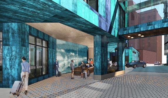
west hotel entrance feature wall (image selection, image abstraction, and renders by self)
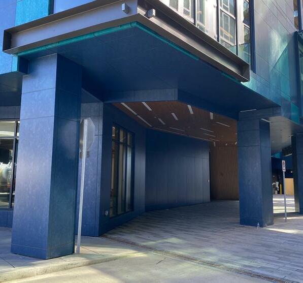
 construction photograph
west hotel entrance and drop-off (09/24/21, by self)
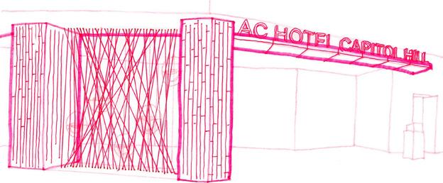
process sketch
15
west hotel entrance and drop-off (linework export and markups on trace by self)
construction documents
wall sections
(initial model, sheet set-up and major model / drawing edits by self)
process sketches
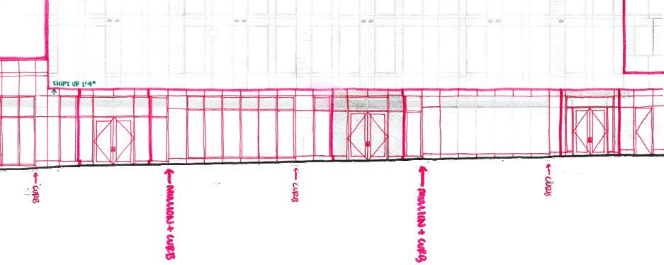
east elevation, retail curtainwall used to study options for reducing far left door height (linework export and markups on trace by self)

-----FLR HOTELAH815 AH850RETAIL Q/Q #3Q/Q #3 - RQ/Q #3 - R 509Q/Q #3709 Q/Q #3Q/Q #3RESTAURANT BAR H1101 AH815-TOP OF COPING HOTEL137'-BAR GH105 AH811 Sim-----10 FLR HOTELAH816 4-Q/Q #1813 Q/Q #1713 Q/Q #1613Q/Q #1Q/Q #1313 Q/Q #1213 RETAIL GH120 11 SIM SIMTOP OF COPING HOTEL3/4" 1' 1/4" 11' 0" 10'-5 1/8" HANGER L4x4x1/4 4" ASI 003H 137' - 9" 5'-0" 1'-0" 1'-9" 8"----10 FLR HOTELAH816-KING #2215 RETAIL GH120515KING #2 - L 715 KING #2 - L 815KING #2 - L 1015 AH810 Sim AH820 AH850 SimTOP OF COPING HOTELASI 003H 137' - 9"----10 FLR HOTELAH816H1101 KING #2 - RKING #2 - R 721 KING #2 - R KING #2 - R 521 KING #2 - R 321 KING #2 - R 421 Sim AH820 SIM AH820 SIM 3/4"TOP OF COPING HOTEL137'-----10 FLR HOTELAH816RESTAURANT BAR H1101 WARMING KITCHEN GH110 KING #2321 KING #2 - R 421 KING #2 - R 521 KING #2 - R 621 KING #2 - R 721 KING #2 - R 821KING #21021 Sim SIM AH810 3 Sim AH850 2 Sim 9'-0" 1'-5"TOP OF COPING HOTELASI 003H 137' - 9"AH815-15'-5" 3'-4" 2'-0 1/4" 0'-7" 1'-2" GREEN ROOF AND PAVER EDGE, SEE PLAN----10 FLR HOTEL1031 KING #1 SUITE 931 Q/Q #1 SUITE 831 Q/Q #1 SUITE 631 Q/Q ADA #1 SUITE 331 AH820 SIM 2 137'AH814 FLR HOTELQ/Q #2211 RETAIL GAS METER ROOM P13102 FLR HOTEL-16' 1/4" 48'-10 5/8" 14'-0" MIN STEEL BEAM, SEE STRUCT 14'-6 7/8" RFI 050 50' - 11"AH81715'-5" 3'-4" 2'-0 1/4" GREEN ROOF AND PLAN RETAIL GH120 Washington, DC 20007 202.600.7230 202.600.7280 info@r2l-architects.com 12435 Park Potomac Ave, St 300 Potomac, MD 20854 301.881.1441 www.skaengineers.com Smislova, Kehnemui & Assoc PLUMBING ENG -ALL CIVIL ENGINEERING 12950 Worldgate Dr, St 100 Herndon, VA 20170 703.713.0300 www.ktagroup.com KTA Group 11860 Sunrise Valley Dr, St 200 Reston, VA 20191 Wiles Mensch Corporation MECHANICAL ENG -HOTEL 10411 Motor City Dr, St 550 Bethesda, MD 20817 www.edg2.com EDG2 Engineering Design Group ELECTRICAL ENG -ALL Petersburg, FL 33716 727.210.0492 www.powerdesigninc.us Power Design, Inc 19955 Highland Vista Dr, St 170 Ashburn, VA 20147 www.geoconcepts-eng.com GeoConcepts Engineering, Inc ENVIRONMENTAL ENG 12950 Worldgate Dr, St 100 Herndon, VA 20170 703.713.0300 www.ktagroup.com KTA Group INTERIOR DESIGN -HOTEL 520 Nicollet Mall, St 200 Minneapolis, MN 55402 www.dlrgroup.com DLR Group LIGHTING DESIGN -RESI 11600 Ninth Street North Petersburg, FL 33716 www.powerdesigninc.us Power Design, Inc 8405 GREENSBORO DRIVE, STE 500 MCLEAN, VA 22102 LIGHTING DESIGN -HOTEL 1671 House Street NE Belmont, MI 49306 www.wpf-engineering.com WPF Engineering, LLC CSX EAST GREYSTAR GP II, LLC AH340 SCALE: 1/4" 1'-0" 1 WALL SECTION AT EAST 01 -BUILDING 1 SCALE: 1/4" 1'-0" 2 WALL SECTION AT EAST 02 -GROUND FLOOR -BUILDING 1 SCALE: 1/4" = 1'-0" WALL SECTION AT EAST 03 -BUILDING SCALE: 1/4" 1'-0" WALL SECTION AT EAST 04 -BUILDING SCALE: 1/4" 1'-0" 5 WALL SECTION AT EAST 05 -BUILDING 1 SCALE: 1/4" 1'-0" 6 WALL SECTION AT EAST 06 -BUILDING 1 SCALE: 1/4" 1'-0" 7 WALL SECTION THROUGH EAST RECESSED DOOR -BUILDING 1 SCALE: 1/4" 1'-0" 11 WALL SECTION AT EAST 02 -UPPER FLOORS -BUILDING 1 9 WALL SECTION THROUGH RECESSED RETAIL DOOR -BUILDING SCALE: 1/4" 1'-0" 10 WALL SECTION THROUGH LOADING DOCK DOOR -BUILDING SCALE: 8 WALL SECTION THROUGH RETAIL @ SECOND FLR GREEN RF BUILDING
construction documents
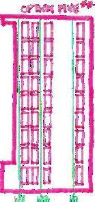
typical floor plan (initial detailing, drafting, sheet set-up and major drawing edits by self)
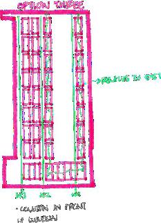
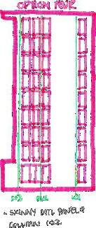
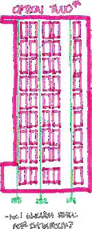
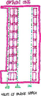
process sketches
north elevation studies (linework export and sketches by self, decision and model changes by self)
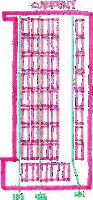
C FE FD FE 1 AH331 AH311 63 HP 62 61 60 HN HM HL HK HJ HI HE HF HG AH331 Q/Q #2529Q/Q #2525 Q/Q #1523 KING #2521 Q/Q #1519 KING #3 SUITE 517Q/Q #1513 Q/Q #2511 Q/Q #3 - R 509 KING #4507 KING #1505 Q/Q #2503-KING #2 - L 508 KING #1510 Q/Q ADA #1 512 ELEC H505Q/Q #1526528PE-02PE-03 STAIR 1-2 CORRIDOR H501 ELEVATOR LOBBY H500 AH310 AH312 AH312 AH312 AH325 AH601 AH603 AH602 AH345 AH345 1 AH330 AH310 2 AH310 AH341 AH340 4 AH340 3 AH340 AH341 8 AH341 9- 0 20 - 0 250 250 255-0 3B 4C 7B 9C 3B 3B 3B 9C 3B 4C 7B 9C 7B 3B 9C 3B 3B 3B 3B 1A 3B 3B 9C 9B 4C AH350 9C HK100 HK100 HK100 HK100 HK100 HK100 HK100 HK100 HK100 HK100 HK100 HK100 HK100 HK100 HK100 HK100 HK100 HK100 HK100 HK100 H504 H505 H508 H507 06 4418 AH313 9C 9C 9C 9C 1A 2B 9C 2B 9C 9C 2B 2B 9B 9B 9C 5 -6 89 4C 4C 4C 3B 9C 9C 11 AH340 AH605 AH730 15 AH332 AH902 7A ASI 003H ASI 003H ASI 003H ASI 004H 111112 218 158 2 - 78 68-478 4- 1 4-8 2 -8 2 -8 -2 5- 34 4-81 4- 1 -8 2 4-81 -8 222 -8 4- 2 4-81 3-822863 258 47 3-138 41 / 9112 4- 3/ 1-18 4141 8315 812 12122-163 11 15 33 -11 -81 4-8 8 9- 1 3- 14 1-958 0-1 14 -7 8 -0 8 -11 10 121034 7-1 3-312 18-038 35/88/81/ 122 1-145 148 23 1114 243 15 4-918 22/ 41 / 134 11 /5 8 40310 -8 250 463/ 3-81/4 2018 2018 2018 20182 111038 107/ 1-101/4 18 3-10/ 21/8 4-81/2 41/2 90 0 247/ 6-0 8-478 58 412 4-81/2 8 18 10018 152072 5-1078 93/4 15 0 2018 2018 2412 58 42 41/2 11158 12 12 253/ 1115881/ 5-258 12 121 38 25340 881/84014 11 01 11 11 25 22 20 130 - 5/8 9C RFI 052 RFI 052 9/ 8STORAGE H503 -8 61 60 HE HF AH345 AH341 Q/Q ADA #1 SUITE 360 SF 5-414 -0 HK100 11 AH3408 -8 463/81 1-101 1/8 5/8 4-81/2 4-812 8 2218 2501 61 60 HE HF AH341 360 SF 452 SF HK100 HK100 H406 AH3408 -81 4/ 3-8 1-1 1-41/8 5918 4-812 4-812 88 20 2 0 11 61 60 HE HF AH345 AH341 452 SF 360 SF HK100 11 AH3405 8 -8 250 463/ 3-814 1-1014 1/8 5/8 41/2 4-812 8 18 21 LEGEND GENERAL NOTES KEYNOTES 1. REFER TO A001 FOR ADDITIONAL NOTES, ABBREVIATIONS & SYMBOLS. 2. REFER TO AH700 SERIES SHEETS FOR PARTITION SCHEDULE, FIRE RESISTANCE RATED WALL TYPES, & FLOOR CEILING ASSEMBLIES. ALL INTERIOR DRYWALL PARTITIONS ARE TYPE-1 U.N.O. 3. REFER TO AH500 SERIES SHEETS FOR ACCESSIBILITY AND TYPICAL DEVICE MOUNTING REQUIREMENTS. 4. REFER TO AH500 SERIES FOR TYPICAL BATHROOM REQUIREMENTS, INCLUDING GRAB BAR SHOWER SEAT BLOCKING DIAGRAMS. 5. REFER TO LANDSCAPE DRAWINGS FOR PLANTINGS AND PAVING DETAILS AT OUTDOOR AREAS. CROSS & DRAINAGE SLOPES AT PAVER & DECKING PEDESTRIAN SURFACES SHALL NOT EXCEED 2%. 6. WHERE WALLS OF DIFFERENT TYPES ARE SHOWN TO ALIGN IN PLAN, ALIGN FINISHED FACE OF WALLS. 7. AT INTERIOR DOORS, INSIDE FACE OF HINGE-SIDE JAMB SHALL BE 4" MINIMUM FROM FACE OF ADJACENT INTERSECTING PARTITION, U.N.O 8. AT INTERIOR DOORS INSTALLED IN MASONRY PARTITIONS, INSIDE FACE OF HINGE-SIDE JAMB SHALL BE 8" MINIMUM FROM FACE OF ADJACENT INTERSECTING PARTITION, U.N.O. 9. PROVIDE WATERPROOFING AT INTERIOR FACES & FLOORS OF CMU ENCLOSED SHAFTS THAT ARE EXPOSED TO WEATHER. 10. SEE AH300 SERIES EXTERIOR ELEVATIONS AND AH700 SERIES WINDOW AND PANEL SCHEDULES FOR WINDOW & TERRACE DOOR TYPES, RAILINGS, AND EXTERIOR WALL CONDITIONS. 11. SKIM COAT & PAINT ALL EXPOSED COLUMNS IN FINISHED INTERIOR SPACES. 12. EXPOSED COLUMNS AT EXTERIOR SPACES TO HAVE ACM CLADDING, FINISH AS NOTED ON BUILDING ELEVATIONS. 13. PROVIDE CONCEALED FIRE-TREATED BLOCKING FOR PARTITION-MOUNTED EQUIPMENT, FIXTURES, & MILLWORK, AND AT GRAB BAR SHOWER SEAT LOCATIONS WHERE REQUIRED. 14. FURNITURE SHOWN FOR REFERENCE ONLY. 15. ALL BALCONY TRANSITIONS TO VERTICAL BUILDING WALLS TO RECEIVE TRAFFIC COATING. WALKING SURFACES, EDGES AND UNDERSIDE OF BALCONIES TO BE GROUND SMOOTH AND RECEIVE SKIM COAT AND PAINT. 16. ALL STRUCTURAL STEEL AND MISCELLANEOUS METALS NDICATED ON ARCHITECTURAL DRAWINGS, BUT NOT SHOWN ON STRUCTURAL DRAWINGS, ARE TO BE DESIGNED AND ENGINEERED BY SUBCONTRACTOR/SUPPLIER/ FABRICATOR OF SYSTEM OF COMPONENTS WHICH THEY ARE SUPPORTING 17. ALL AMENITY INTERIOR PARTITIONS TO BE TYPE-1A U.N.O. 18. GUESTROOMS ON THE THIRD AND FOURTH FLOOR OF BUILDING TO BE PROVIDED WITH HARDWIRED INTERNET CONNECTIONS, SEE ELECTRICAL DRAWINGS FOR BALANCE OF INFORMATION. 19. FURNITURE AND EQUIPMENT IN AH SERIES PLANS SHOWN FOR REFERENCE ONLY. REFER TO IDH AND INH SERIES DRAWINGS REGARDING FURNITURE SPECIFICATIONS AND LOCATIONS. REFER TO FOODSERVICE DRAWINGS REGARDING EQUIPMENT SPECIFICATIONS AND LOCATIONS. 20. REFER TO AH SERIES DRAWINGS FOR BUILDING 1 CONSTRUCTION DETAILS AND DIMENSIONS, REFER TO INH SERIES DRAWINGS FOR FINISH INFORMATION. 21. REFER TO FINISH SCHEDULE ON AH506 FOR HOTEL BACK-OF-HOUSE FINISHES. CMU WALL CONCRETE COLUMNS SLOPED COLUMNS TOPPING SLAB WITH TILE FINISH FLOOR ROOF DRAINS, SEE PLUMBING PROPERTY LINE RECESSED FIRE EXTINGUISHER & CABINET BRACKET-MOUNTED FIRE EXTINGUISHER TRENCH DRAIN SANITARY DRAINS, SEE PLUMBING ACCESSIBLE GUESTROOM WALL TAG, SEE PARTITION SHEET CONNECTOR BRIDGE B1 TO B2 DRINKING FOUNTAINS CONTROLLED ACCESS DOOR GREEN ROOF AREA GRAVEL PATH HOSE BIB MOP SINK BOLLARD HYDRATION ROOM EXHAUST SHAFT, SEE MECHANICAL ELECTRICAL ROOM EXHAUST SHAFT, SEE MECHANICAL LAUNDRY CHUTE, SEE MECHANICAL DRYER EXHAUST SHAFT, SEE MECHANICAL SCUPPER; COORD W/ DRAINAGE AREAS SPECIFIED IN A060 SERIES SHEETS BIKE RACK ELECTRICAL VEHICLE CHARGING STATION. CHARGING CONTROLS NOT TO EXCEED 48" AFF. GREEN ROOF ASSEMBLY C, SEE L701 STAIR PRESSURIZATION SHAFT, SEE MECHANICAL PIPING, SEE PLUMBING UNDERGROUND GREASE INTERCEPTOR, SEE PLUMBING. TRAFFIC RATED LIDS REQUIRED O/A SHAFT, HOTEL, SEE MECHANICAL SLAB OPENING FOR GENERATOR, SEE MECHANICAL SLAB OPENING FOR VRF LINES, SEE MECHANICAL SLAB OPENING FOR GAS LINES, SEE PLUMBING RETAIL KITCHEN EXHAUST SHAFT, SEE MECHANICAL GREASE PIPE CONDUIT, SEE PLUMBING HUFCOR OPERABLE PARTITION GLASS PANEL RAILING, SEE AH730 SERIES CURB SEPARATING GREEN ROOF AND/OR IMPERVIOUS DRAINAGE AREAS, SEE 4/L702 NON-SMOKING SIGNAGE, SEE AH501 MECHANICAL LOUVER 1 2 3 12 13 GREEN ROOF PLANTER GUESTROOM EQUIPPED WITH VISUAL ALARM 20 21 22 23 BIORETENTION PLANTER TOPPING SLAB RIDGE LINE TOPPING SLAB IMPERVIOUS AREA SEPARATION LINE Washington, DC 20007 202.600.7230 202.600.7280 info@r2l-architects.com 12435 Park Potomac Ave, St 300 Potomac, MD 20854 301.881.1441 www.skaengineers.com Smislova, Kehnemui & Assoc PLUMBING ENG -ALL CIVIL ENGINEERING 12950 Worldgate Dr, St 100 Herndon, VA 20170 703.713.0300 www.ktagroup.com KTA Group 11860 Sunrise Valley Dr, St 200 Reston, VA 20191 Wiles Mensch Corporation MECHANICAL ENG -HOTEL 10411 Motor City Dr, St 550 Bethesda, MD 20817 www.edg2.com EDG2 Engineering Design Group ELECTRICAL ENG -ALL Petersburg, FL 33716 727.210.0492 www.powerdesigninc.us Power Design, Inc 19955 Highland Vista Dr, St 170 Ashburn, VA 20147 www.geoconcepts-eng.com GeoConcepts Engineering, Inc ENVIRONMENTAL ENG 12950 Worldgate Dr, St 100 Herndon, VA 20170 703.713.0300 www.ktagroup.com KTA Group INTERIOR DESIGN -HOTEL 520 Nicollet Mall, St 200 Minneapolis, MN 55402 www.dlrgroup.com DLR Group LIGHTING DESIGN -RESI 11600 Ninth Street North Petersburg, FL 33716 www.powerdesigninc.us Power Design, Inc 8405 GREENSBORO DRIVE, STE 500 MCLEAN, VA 22102 LIGHTING DESIGN -HOTEL 1671 House Street NE Belmont, MI 49306 www.wpf-engineering.com WPF Engineering, LLC CSX EAST GREYSTAR GP II, LLC TYPICAL FLOOR PLAN
AH240 SCALE: 1/8" 1'-0" 1 05 TYPICAL FLOOR PLAN -HOTEL 2 03 THIRD FLOOR PLAN -HOTEL ADA SCALE: 1/8" 1'-0" 3 04 FOURTH FLOOR PLAN -HOTEL ADA SCALE: 1/8" 1'-0" 4 06 SIXTH FLOOR PLAN -T-31 SUITE
-
17
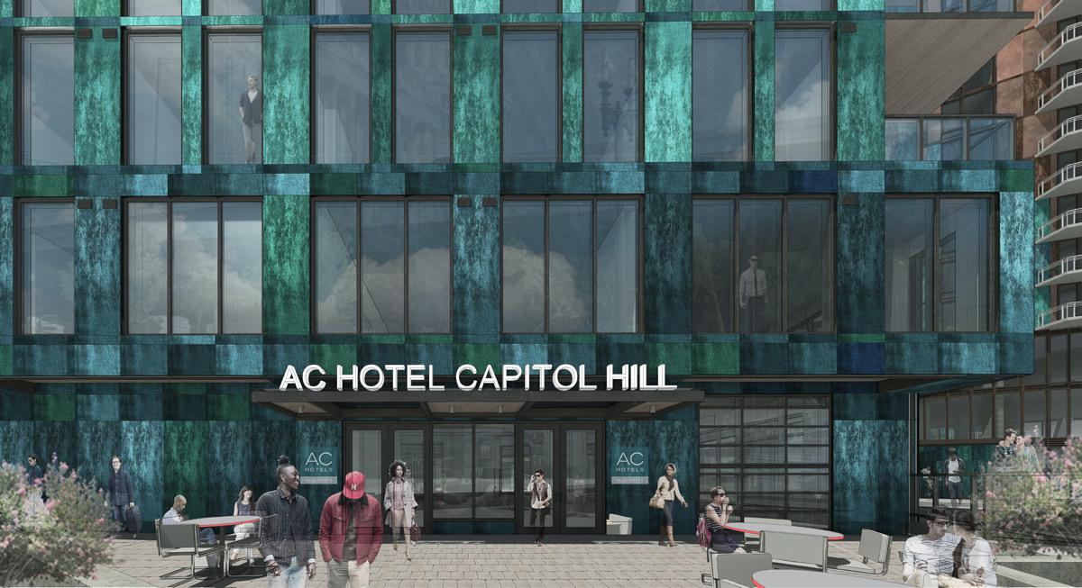
presentation drawing
view of the east hotel entrance and canopy (modeling, raw render, linework export, and postproduction by self)
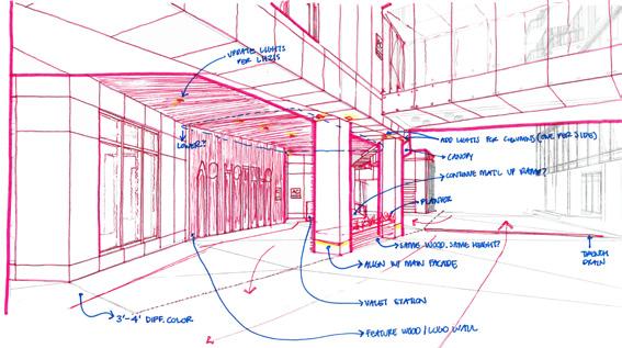
design drawing
east entry canopy perspective used to futher refine the canopy design and wood slat placement (design, modeling, and linework export by self)
62 HF HG GLASS JOINTS, ALIGN WITH CENTERLINES OF BEAMS BELOW BUILDING FACADE SLOPE TO ALIGN WITH BUILDING OVERHANG OPEN OPEN OPEN 62 HF HG 0" 0" SECONDARY CANOPY BEAMS INTEGRAL GUTTER (ABOVE) TO TOSTEEL CANOPY, PAINTED 1/2"METAL PANEL FACADEACM INFILL PANEL CEILING, COLOR MPH-02 POWER, SEE ELECTRICAL DRAWINGS STEEL HSS WITH WELDED TOP AND BOTTOM PLATES, REFER TO SH SERIES DRAWINGS. PAINTED SW 7048 URBANE BRONZ SEE ELEVATIONS IN AH300 SERIES STEEL CANOPY SUPPORT HSS BEYOND, REFER TO SH SERIES STEEL PLATE GUTTER WELDED TO HSS BELOW, SLOPE TO DR TER, SEALED AND TIED TODRAIN 1/2" 1/2" 1/2"CONCRETE SLAB STEEL CANOPY SUPPORT 1/2" 1/2" 1/2" Washington, DC 20007 12950 Worldgate Dr, St 100 11860 Sunrise Valley Dr, St 200 Reston, VA 20191 Bethesda, MD 20817 202.466.2232 www.edg2.com EDG2 Engineering Design Group Power Design, Inc GEOTECHNICAL ENG ENVIRONMENTAL ENG 12950 Worldgate Dr, St 100 Herndon, VA 20170 www.ktagroup.com 520 Nicollet Mall, St 200 Minneapolis, MN 55402 www.dlrgroup.com ARCHITECTURAL DESIGN LIGHTING DESIGN -HOTEL AH740 EAST ENTRY CANOPY ELEVATION -BUILDING EAST ENTRY CANOPY TRANSVERSE SECTION -BUILDING
documents
detailing, drafting, sheet set-up, and major drawing edits by self)
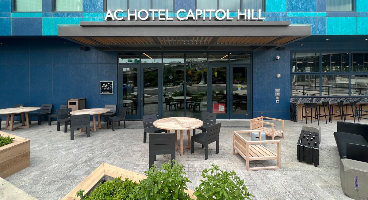
photograph east hotel entrance and canopy (06/16/22, by self) 19
construction
canopy details (initial modeling,
construction
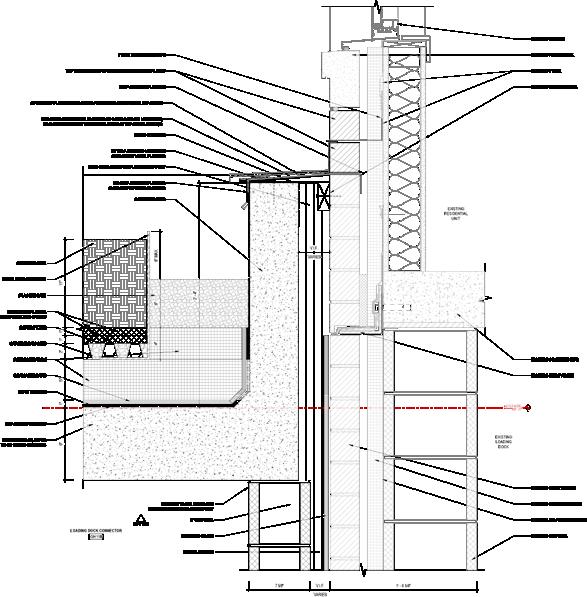
envelope coordination
second floor green roof connection to adjacent building; detail worked out between R2L, envelope consultant, and contractor (detail by self)
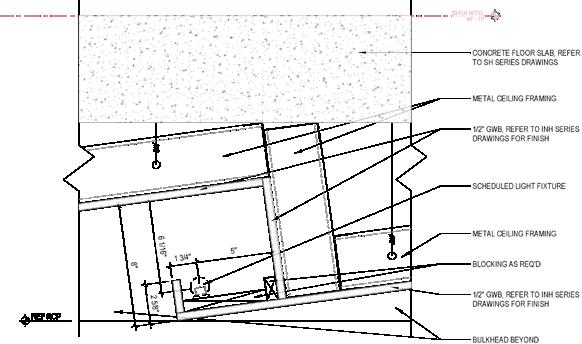
interior design coordination
second floor meeting room ceiling feature; design intent by DLR and detail development, documentation, and MEP coordination by R2L (light cove detail by self)
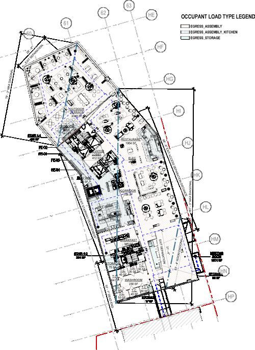
code & life safety coordination
eleventh floor egress plan (by self)
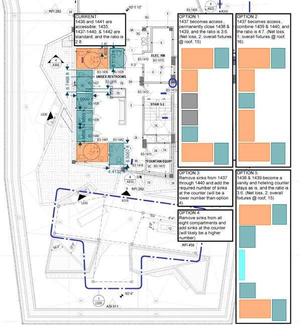
accessibility coordination
bluebeam markup of Building 3 roof washroom used to coordinate preferred solution between R2L, accessibility consultant, and contractor in order to achieve the required ratio of accessible to standard toilet compartments (proposed options and markup by self)
 construction photograph
21
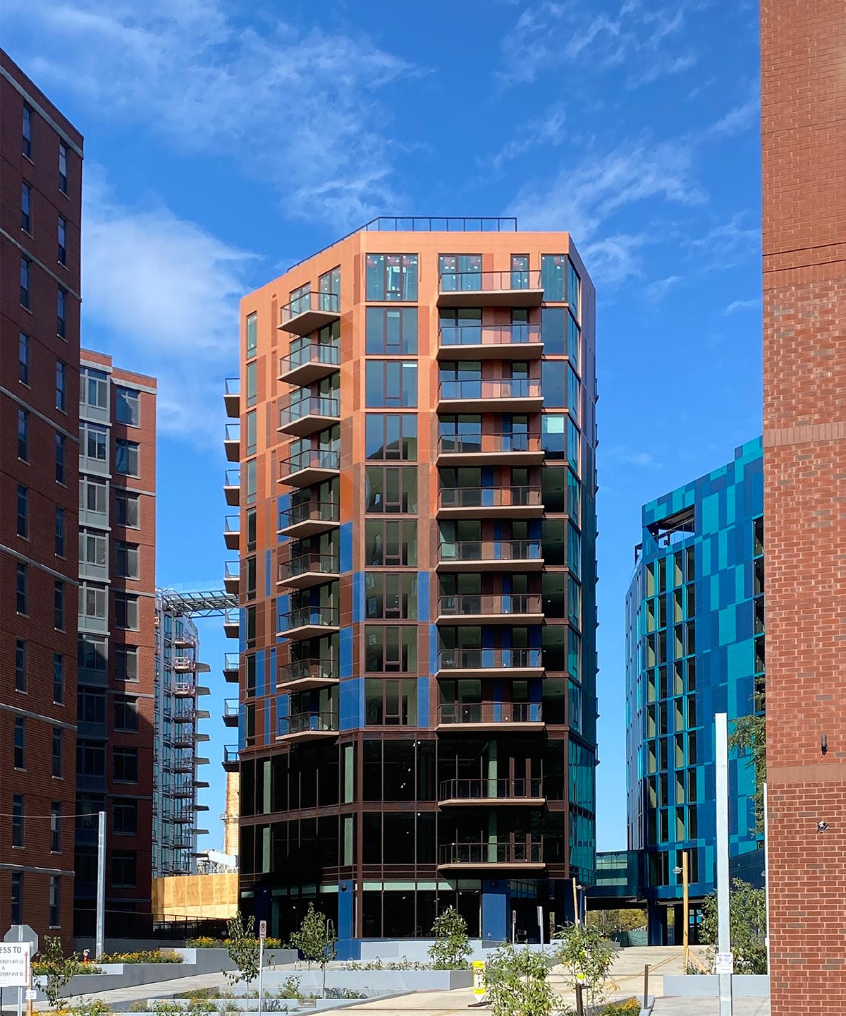
south end of Building 2, looking north, with Building 3 to the left and Building 1 to the right Bridges 2, 3, and 4 and I-695 visible in the background (10/25/21, by self)
bridges and connections (photographs and diagram by self)
BRIDGE
4
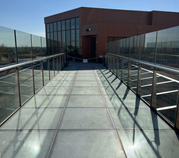
Connects the roof levels of Building 2 and 3, allowing residents to access the roof-level amenities located in the other building without having to go down to the ground floor. Additionally, a walking or running route is created along the perimeter of both buildings across the bridge. It’s an open-air, all-glass skybridge with very visible structure and fritted glass to walk on. Structurally, two steel trusses are connected with tube steel; it bears on both Buildings 2 and 3 through haunches, embeds, and concrete beams. The skybridge also has steel outriggers which were required for zoning.
ELEVATOR & STAIR COURTYARD CONNECTION
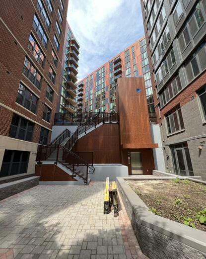
Connects the central courtyard of CSX with the west courtyard at 100 Eye Street. Since all four buildings are now managed out of the leasing office in Building 2, the elevator provides an accessible route from CSX to Capitol Yards. The connection also allows Capitol Yards residents to access the amenities and the dog park in Buildings 2 and 3.
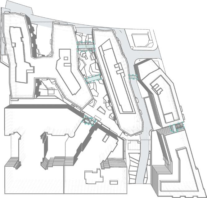
Bridge 2 connects the second floor meeting room space in Building 1 to the coworking space on the second floor of Building 2. Hotel guests can use the bridge to access the gym on the ground floor of Building 2 while people using the coworking space can rent the meeting rooms if needed. Bridge 3 connects the coworking space on the second floor of Building 2 with the second floor of Building 3, allowing residents in Building 3 easier access to the office space if they work there. They’re a pair of conditioned, glass wall and glass ceiling bridges with hidden structure, meant to appear as frameless glass volumes. The glass is fritted on the ceiling and south wall while clear on the north. Structurally, they bear on the buildings on both sides through haunches, embeds, and concrete beams. The west sides of both bridges are the fixed ends and the east sides are designed for lateral movement.
BRIDGE 1 & ZONING TRELLIS
Connects the 12th floor of ORE 82 EYE with the 11th floor of Building 1. It appears as an extension of Building 1’s metal panel facade; structurally, it bears completely on Building 1 on diagonal steel members with an expansion joint at the interface with ORE 82 EYE. The zoning trellis caps off an otherwise irregular shaped court facing NJ Avenue.
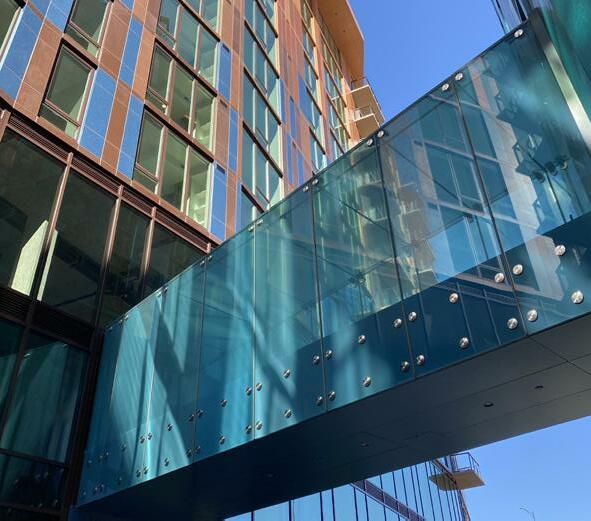
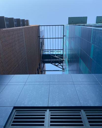
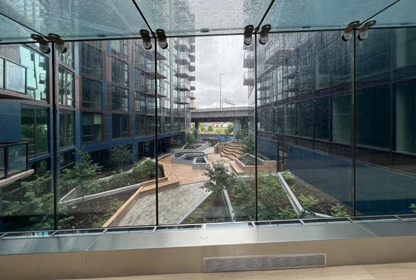
2 & 3
BRIDGES
23
construction photographs
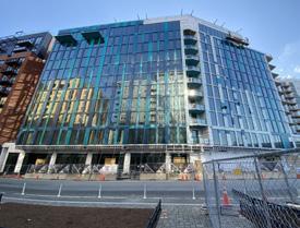
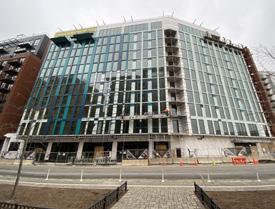
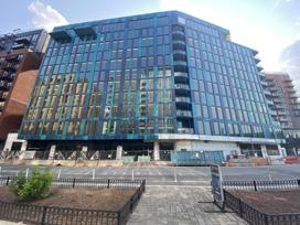
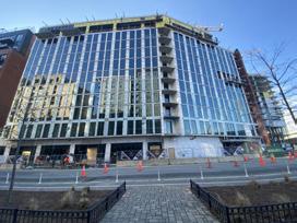
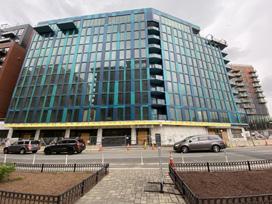
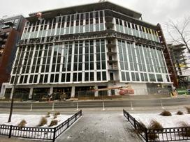
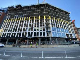
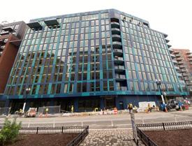
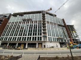
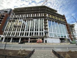
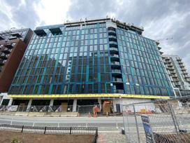
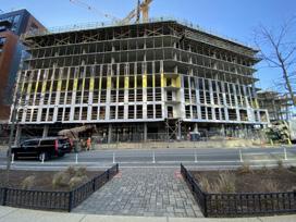
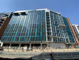
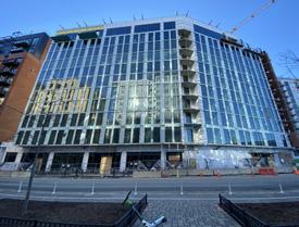
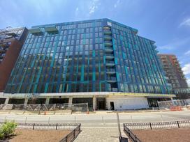
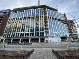
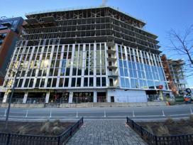
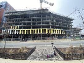
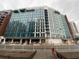
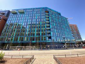
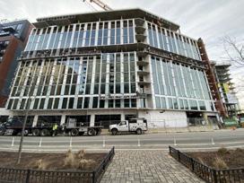
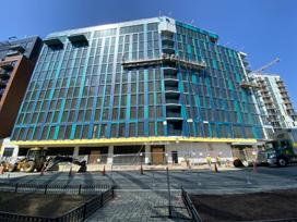
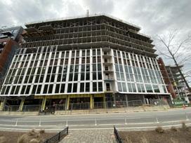
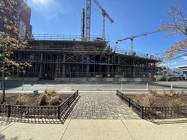 progress photographs of the hotel taken from across New Jersey Avenue, 09/2020 to present (by self)
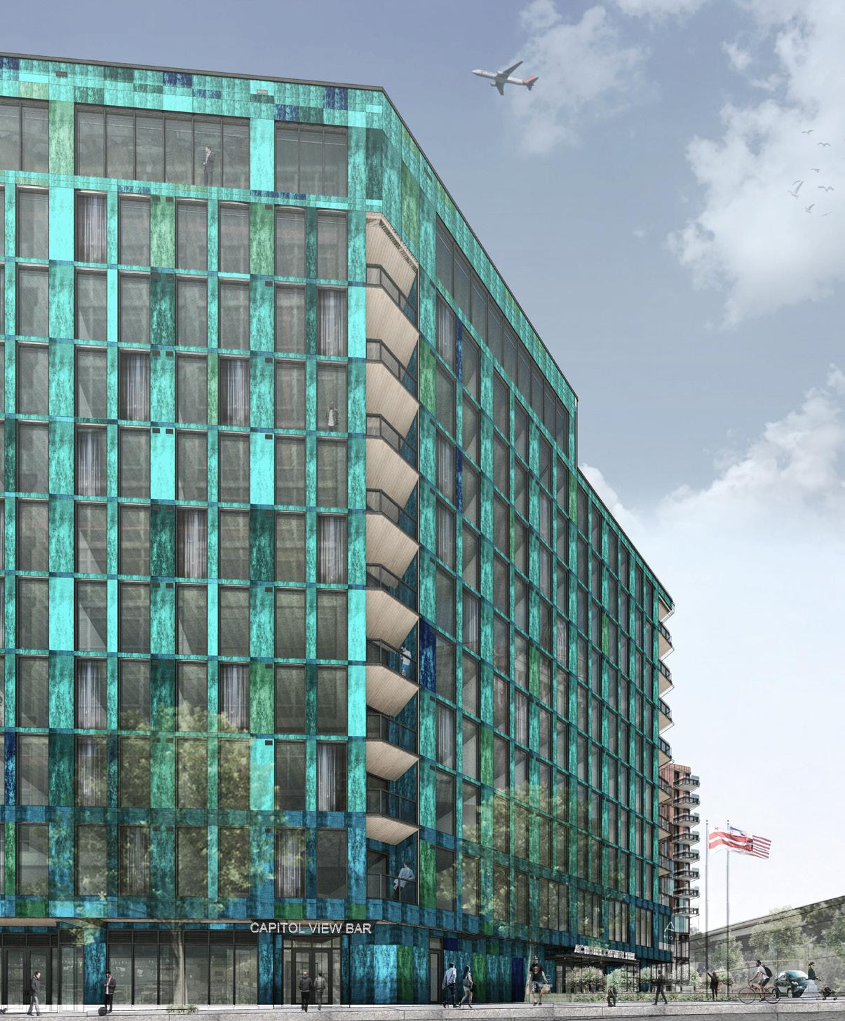
presentation drawing
25
view of the east facade and restaurant entrance (modeling, raw render, linework export, and postproduction by self)
WEST 2ND
Charlottesville, VA
R2L:Architects role: Primary Staff programs used: Revit 2018, Photoshop, and Illustrator
I came onto this project after the schematic design phase and learned that the project had a somewhat difficult past. The city put out an RFP for a housing project that could also provide a permanent home for the Charlottesville City Market. The city and the vendors disagreed with which proposal should proceed further, but the city went with their own choice.
The project was further inhibited by an initial design that called for an expensive, two-anda-half story underground garage, unrealistic structural system, and inefficient typical residential floors.
The project came to R2L:architects as the firm is known for high quality, cost-effective design. A number of changes included reducing the amount of excavation, changing to a concrete structural system, increasing rentable office space, and more efficient residential floors.
My initial contributions to this project included presentation drawings for board of architectural review meetings that we were required to present at once every month. Additionally, I worked on almost every drawing including plans, sections, elevations, egress plans, zoning information, unit sheets, stair and elevator details, and exterior details. The exterior details were particularly interesting as they allowed me to work closely with the principals and envelope consultants.
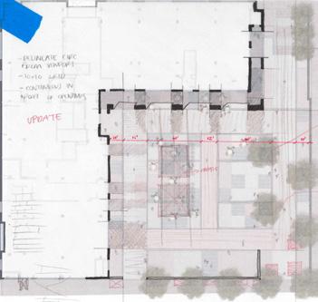
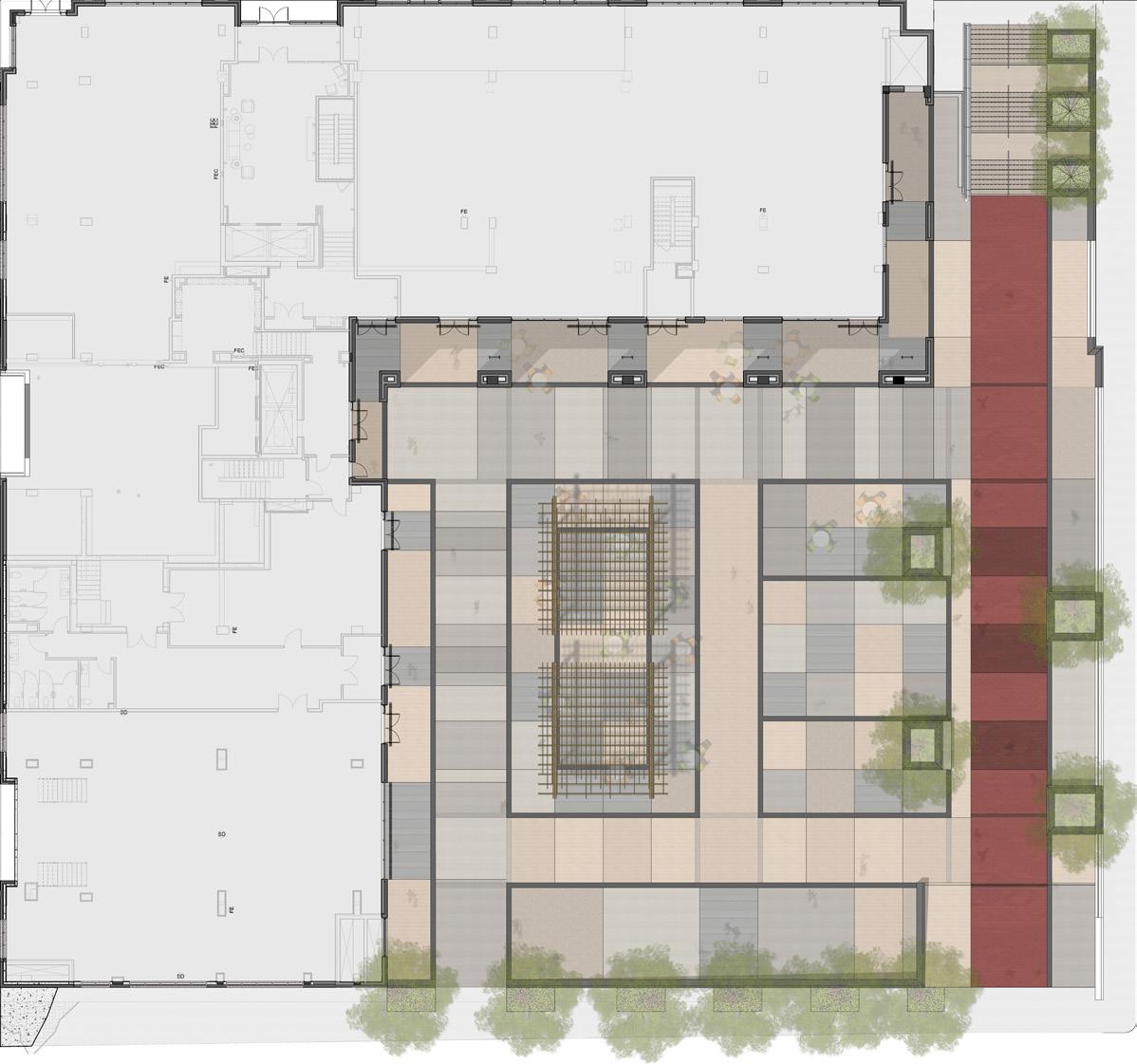
I also really enjoyed working on the plaza paving plan, seen on page 20. The plaza had gone through various iterations and was restricted to about 30% cast stone and 70% stamped concrete, for budget reasons. The design I proposed established a subtle 10’x10’ grid for the vendor tents with cast stone borders to separate the vendor space from the circulation space. Various gray hues of concrete reach across the path to hide the incongruity of the lines extending from the building’s 20’ openings and the 10’ tent grid.
26
 Exterior rendering of northeast corner (by self).
presentation drawings
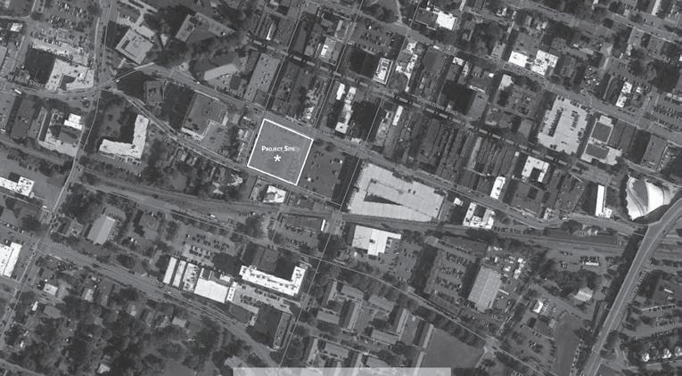
top: context map (by project manager);
bottom:
 plaza paving plan with inset showing process drawing (by self)
presentation drawings
top left and right: building massing and program axonometrics (by self);
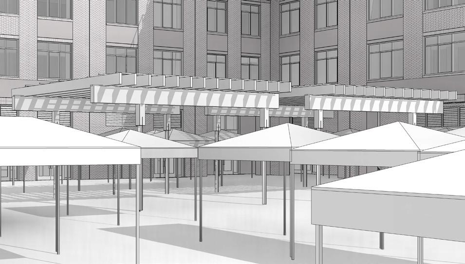
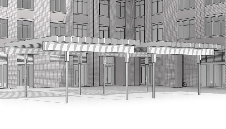
middle: plaza trellis during the week (design input provided by self, trellis model and export by others);
bottom: plaza trellis during Charlottesville City Market (design input provided by self, trellis model and export by others)
29
presentation drawings
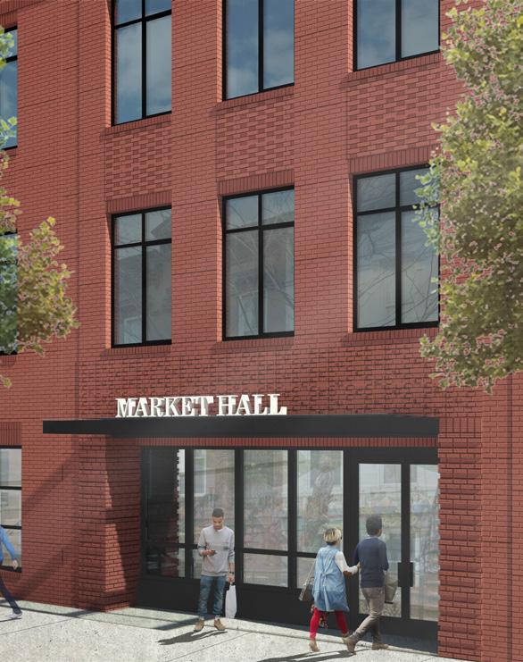
left: indoor market hall entrance (raw render and linework export by self, post-production by other with input by self)
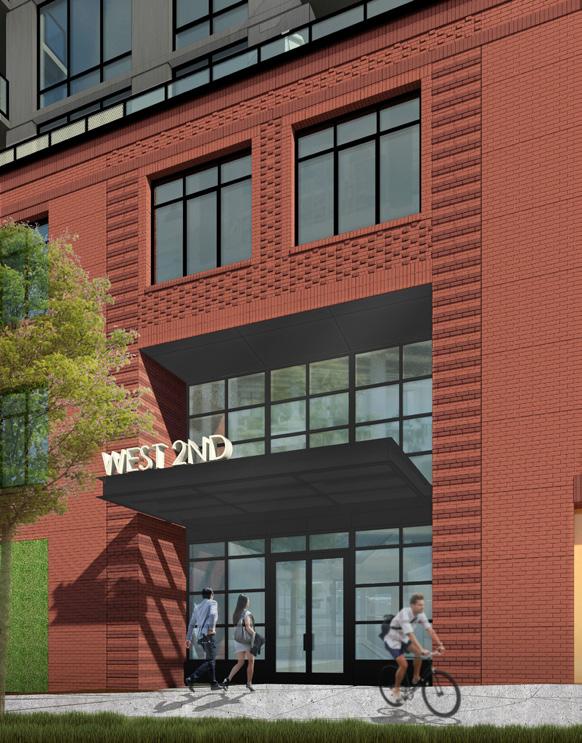
right: residential lobby entrance (raw render, linework export, and post-production by self)
presentation drawings
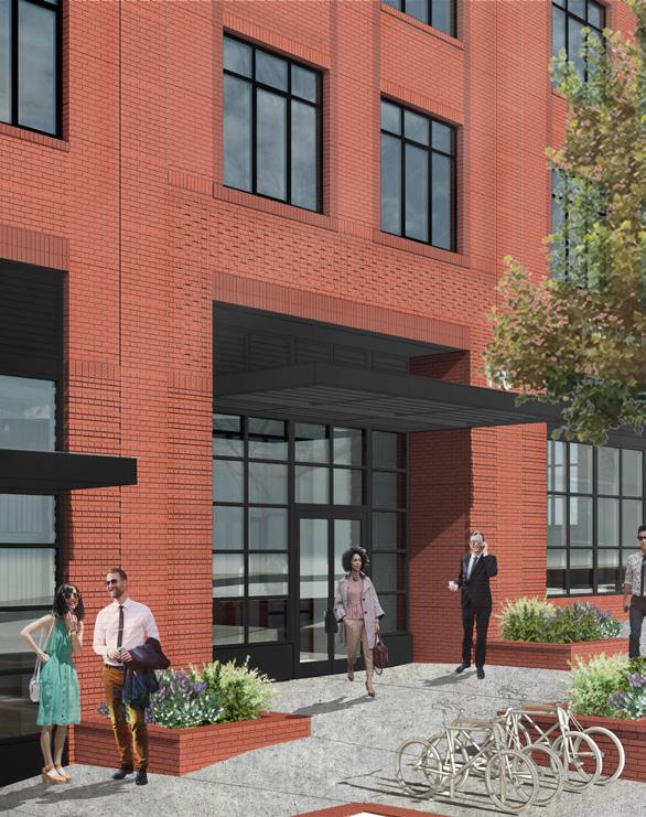 left: office lobby entrance (raw render and linework export by self, post-production by other with input by self)
31
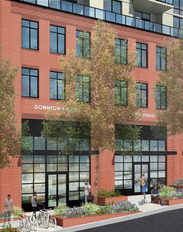
right: retail entrances (raw render, linework export, and post-production by self)
construction documents
ground floor plan
(initial model by others, sheet set-up and major model / drawing edits by self)
presentation drawings
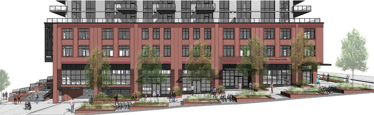
north elevation perspective
(raw render, linework export, and postproduction by self)
UP DN SD SD SD SD SD SD DN FE FE FE FEC FE FE FE FE FEC SD 2 2 4 4 5 5 6 6 9 9 10 10 A A B B C C E E F F G G H H J J K K A3.12 A3.13 1 A3.30 7 7 463'-10 9/16" 10'-11" 28'-0" 28'-0" 28'-0" 28'-0" 28'-0" 28'-0" 24'-6" 15'-11" 16'-10" 27'-7" 28'-0" 28'-0" 28'-0" 18'-3" 9'-9" 28'-0" 10'-11" RETAIL B ETRY AREA SEE P1 FLOOR PLAN D D 35'-0" 7'-11" A6.22 A6.22 A6.10 5 A3.40 A3.40 A3.40 A3.43 A3.41 2 3 3 A3.42 A3.42 A3.42 A3.41 INDOOR RETAIL MARKET G06 LOBBY G18 MEN'S RESTROOM G15 FUTURE CATERING KITCHEN G12 OFFICE LOBBY G03 RETAIL B G05 FAMILY RESTROOM G17 WOMEN'S RESTROOM G16 467'-10" 467'-6" 473'-1 7/8" STAIR B ELEVATOR 5 ELEVATOR 2ELEVATOR 1 ELEVATOR 3 ELEVATOR 4 STAIR A ST-A 2 TD TD TD TD TD TD TD TD 79'-11 5/8" 483'-6" 467'-6" 12 467'-6" 467'-6" EVENT VESTIBULE G19 OFFICE VESTIBULE G02 473'-1 7/8" 485'-0 11/16" 473'-1 1/2" 458'-11 3/8" 1A 1C 1C 9C 9C 1C 1C 1C 1C 1C 1C 9C 1C 6 1C 7B 9C 7B 4 9C 1A 6 1A 1C 1A 1A 18 19 20 31 1C 463'-10 9/16" 467'-6" A3.32 A3.32 A3.43 A3.40 137'-4" 32'-4" 6'-8" 110'-4" 47'-8" 22'-3 5/8" 20'-0 3/8" 7'-11 5/8" 8'-0 3/8" 3'-11 5/8" 8'-0 3/8" 19'-11 5/8" 8'-0 3/8" 6'-8" 16'-3 5/8" 8'-0 3/8" 8'-0" 16'-7 5/8" 6'-0 3/8" 3'-11 5/8" 16'-0 3/8" 3'-11 5/8" 16'-0 3/8" 17'-3 5/8" 66'-7 5/8" 12'-8" 6'-11 5/8" 20'-0 3/8" 7'-11 5/8" 20'-0 3/8" 7'-11 5/8" 20'-0 3/8" 7'-11 5/8" 20'-0 3/8" 7'-11 5/8" 20'-0 3/8" 7'-11 5/8" 20'-0 3/8" 4'-11 5/8" 9'-0 3/8" 7'-7 1/4" 20'-0" 7'-11 5/8" 8'-0 3/8" 20'-0 3/8" 20'-0 3/8" 7'-3 5/8" 10'-0 3/8" 32'-3 5/8" 8'-0 3/8" 6'-7 5/8" 20'-0 3/8" 7'-11 5/8" 8'-0 3/8" 5'-11 5/8" EXTERIOR PLAZA G13 G12B G12C G03A OFFICE BACK LOBBY G04 G05B G07 G08 G11B G14B G15 G17 G06A G18 G14A A1.03A A1.03A A1.03A 1 25 25 25 17 15 15 15 15 8'-0" MIN 28 29 STOR G04A A6.30 28 G09 27 27 STAIR C 6 6 A6.23 A1.20 A3.22 A3.22 A3.22 A1.20 A6.30 10 FIRE CONTROL ROOM G07 MAIL ROOM G10 RESIDENTIAL VESTIBULE G08 30 21 21 32 12'-11 1/4" 2'-2 1/4" 11'-11 5/8" 8'-0 3/8" 4'-11 5/8" 8'-0 3/8" 14'-8 3/8" G05C 5'-7 5/8" G06C G11A G12A G19 G01 G21A G21B STAIR VESTIBULE G22 G22B G03B 473'-8 1/16" RESIDENTIAL LOBBY G09 RETAIL A G01 LOWER RESIDENTIAL VESTIBULE G11 TRASH ROOM G13 LOADING DOCK G14 6 7B GENERAL NOTES KEYNOTES LEGEND 1. REFER TO T0.00 SERIES SHEETS FOR ADDITIONAL NOTES, SYMBOLS & ABBREVIATIONS. 2. WHERE WALLS OF DIFFERENT TYPES ARE SHOWN TO ALIGN IN PLAN, ALIGN FINISHED FACE OF WALLS. 3. AT INTERIOR DOORS, INSIDE FACE OF HINGE-SIDE JAMB SHALL BE 6" FROM FACE OF ADJACENT INTERSECTING PARTITION, U.N.O. 4. AT INTERIOR DOORS INSTALLED IN MASONRY PARTITIONS, INSIDE FACE OF HINGE-SIDE JAMB SHALL BE 8" FROM FACE OF ADJACENT INTERSECTING PARTITION, U.N.O. 5. PROVIDE WATERPROOFING AT INTERIOR FACES OF CMUENCLOSED SHAFTS THAT ARE EXPOSED TO WEATHER. 6. SEE EXTERIOR ELEVATIONS FOR WINDOW & TERRACE DOOR TYPES, RAILINGS, AND EXTERIOR WALL CONDITIONS. 7. SKIM COAT & PAINT ALL EXPOSED COLUMNS IN ALL OCCUPIABLE RESIDENTIAL AREAS AT BUILDING EXTERIOR. 8. PROVIDE CONCEALED FIRE-TREATED BLOCKING FOR PARTITION-MOUNTED EQUIPMENT, FIXTURES, & MILLWORK, AND AT GRAB BAR/SHOWER SEAT LOCATIONS IN ALL TYPE "A" & "B" DWELLING UNITS. SEE SHEET A5.00 FOR TYPICAL GRAB BAR/SHOWER SEAT BLOCKING DIAGRAMS. 9. SEE A700 SERIES SHEETS FOR TYPICAL FIRE RESISTANCE RATED WALL, FLOOR, & CEILING ASSEMBLIES. 10. SEE SHEETS A5.10-A5.11 FOR TYPICAL DEVICE MOUNTING AND INSTALLATION REQUIREMENTS. 11. SEE SHEET A5.12-5.15 FOR TYPICAL KITCHEN DETAILS. 12. SEE SHEET T1.00 SERIES FOR INTERIOR FINISH, ACCESSORY, & APPLIANCE SCHEDULES. 13. SEE FINISH SCHEDULES, CORRIDOR ELEVATIONS, & DETAILS FOR TYPICAL RESIDENTIAL CORRIDOR FINISHES. 14. REFER TO LANDSCAPE DRAWINGS FOR PLANTINGS AND PAVING DETAILS FOR OUTDOOR AREAS, CROSS-& DRAINAGE-SLOPES AT PAVER & DECKING AREAS SHALL NOT EXCEED 2%. 15. ELEVATION OF DRAINS IN LOADING & TRASH ROOMS SHALL BE 4" BELOW FLOOR ELEVATION LISTED, TYP, U.N.O. 16. FURNITURE SHOWN N.I.C BY OTHERS, SHOWN FOR REFERENCE ONLY. 17. INTERIOR GWB AT EXTERIOR WALLS TO BE OMITTED ON SECOND AND THIRD FLOOR OFFICE LEVELS AND INSTALLED DURING FUTURE TENANT FIT-OUT, SHOWN FOR REFERENCE ONLY. GENERATOR INTAKE GENERATOR EXHAUST GREASE DUCT SHAFT, CAP FOR FUTURE CONNECTION OF EQUIPMENT, BY OTHERS CORRIDOR OUTSIDE AIR SHAFT OFFICE OUTSIDE AIR SHAFT OFFICE ELEVATOR OVERRUN OFFICE ELEVATOR VENT SHAFT TERMINATION. CONNECT MOTOR OPERATED DAMPER TO BLDG LIFESAFETY SYSTEM ELEC CONDUIT LOCATION/SHAFT, COORD W/ ELEC DWGS TRASH ROOM EXHAUST SHAFT 10 MECH SUPPLY AIR SHAFT, COORD W/ MECH DWGS 11 GARAGE EXHAUST SHAFT 12 LOADING DOCK LIFT 13 STAIR PRESSURIZATION SHAFT TERMINATION. CONNECT MOTOR OPERATED DAMPER TO BLDG LIFESAFTEY SYSTEM 14 TRASH ROOM CHUTE 15 PLANTERS PLANTED TRELLIS GREEN SCREENS 17 STEEL PLAZA TRELLIS MOP SINK CMU WALL CONCRETE COLUMNS SHEAR WALLS FLOOR ROOF DRAINS, SEE PLUMBING PROPERTY LINE SLOPED COLUMNS FIRE EXTINGUISHER & CABINET BRACKET-MOUNTED FIRE EXTINGUISHER SANITARY DRAIN GREEN ROOF PLANTER ROOF PAVERS WOOD DECK TRENCH DRAIN 19 HOSE BIBB 20 LOADING DOCK DOOR GREEN SCREEN PLANTER 22 ALTERNATING TREAD STAIR W/ HATCH TERRACE DIVIDER BIKE RACK 25 TRANSFORMER VAULT 26 HC ACTUATOR 27 WALK OFF MAT 28 ACTIVE OPERABLE LEAF 29 FIRE PANEL 31 FUEL OIL FILL BOX LOCATION PACKAGE CONCIERGE 32 GUARDRAIL DRAIN WEEP THROUGH PLANTER WALL BASE STRUCTURAL ENGINEERING 3222 N ST NW SUITE 500 Washington, DC 20007 f 202.600.7280 info@r2l‐architects.com 12435 Park Potomac Ave. Suite 300 Potomac, MD 20854 SMISLOVA, KEHNEMUI & ASSOCIATES, PA CIVIL ENGINEERING LANDSCAPE ARCHITECT 11600 Ninth St. N St. Petersburg, FL 33716 t 727‐210‐0492 POWER DESIGN, INC. Charlottesville, VA 22903 t 434‐295‐5624 TIMMONS GROUP ELECTRICAL ENGINEERING ENVELOPE CONSULTANT 1828 L St. NW Suite 950 Washington, DC 20036 t 202‐239‐4199 SIMPSON GUMPERTZ & HEGER CODE CONSULTANT Ashburn, VA 20147 t 703‐481‐2000 f 703‐437‐6432 IBTS ACCESSIBILITY CONSULTANT 10309 Rosser Rd Dallas, TX 75229 pete@skarzenski.com 608 Preston Avenue Suite 200 Charlottesville, VA 22903 11600 Ninth St. N St. Petersburg, FL 33716 t 727‐210‐0492 POWER DESIGN, INC. 200 2nd St SW Charlottesville, VA 22902 Market Plaza, LLC Charlottesville, VA 22903 GROUND FLOOR PLAN A2.10 3 GROUND FLOOR MARKET STALL SCHEDULE B CountType 16' 8' Indoor Stall 58' 12' Indoor Stall 1410' x 8' Indoor Stall 310' x 10' Indoor Stall 5010' x 10' Outdoor Stall 210' x 15' Outdoor Stall 810' x 20' Outdoor Stall 1110' x 30' Outdoor Stall TOTAL: 94
construction documents
fourth floor plan
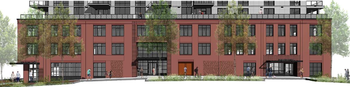
presentation drawings
west elevation perspective (raw render and linework export by self, post-production by other with input by self)
REF P FEC FD UP DN FE FEC SD 2 2 4 4 5 5 6 6 8 8 9 9 10 10 A A B B C C E E F F G G H H J J K K A3.12 A3.13 A3.30 A3.30 1 7 7 17'-5" D D A6.20 A6.10 A3.40 A3.40 A3.40 A3.43 3 A3.41 2 3 3 A3.42 STAIR B ST-B ELEVATOR 3 ELEVATOR 4 STAIR A ST-A REFER TO SHEET A4.00 4 13 14 4 3 3 3 3 3 4 4 6 7B 4 4 4 7B 3 7B 4 7B 6 7B 4 4 TRASH ROOM T403 5'-0" FIRE SVC ACCESS LOBBY T401 5A 3A 2A A3.32 A3.32 T-10 T-08T-06T-04T-02 T-01 T-15 T-17 T-18 T-16 T-14 T-12 407 1 A3.43 A3.40 23 23 23 23 23 23 23 T-02 T-03 T-05 16'-10" 27'-7" 28'-0" 28'-0" 28'-0" 18'-3" 9'-9" 28'-0" 10'-11" A3.22 3 A3.22 A3.22 GENERAL NOTES KEYNOTES LEGEND 1. REFER TO T0.00 SERIES SHEETS FOR ADDITIONAL NOTES, SYMBOLS & ABBREVIATIONS. 2. WHERE WALLS OF DIFFERENT TYPES ARE SHOWN TO ALIGN IN PLAN, ALIGN FINISHED FACE OF WALLS. 3. AT INTERIOR DOORS, INSIDE FACE OF HINGE-SIDE JAMB SHALL BE 6" FROM FACE OF ADJACENT INTERSECTING PARTITION, U.N.O. 4. AT INTERIOR DOORS INSTALLED IN MASONRY PARTITIONS, INSIDE FACE OF HINGE-SIDE JAMB SHALL BE 8" FROM FACE OF ADJACENT INTERSECTING PARTITION, U.N.O. 5. PROVIDE WATERPROOFING AT INTERIOR FACES OF CMUENCLOSED SHAFTS THAT ARE EXPOSED TO WEATHER. 6. SEE EXTERIOR ELEVATIONS FOR WINDOW & TERRACE DOOR TYPES, RAILINGS, AND EXTERIOR WALL CONDITIONS. 7. SKIM COAT & PAINT ALL EXPOSED COLUMNS IN ALL OCCUPIABLE RESIDENTIAL AREAS AT BUILDING EXTERIOR. 8. PROVIDE CONCEALED FIRE-TREATED BLOCKING FOR PARTITION-MOUNTED EQUIPMENT, FIXTURES, & MILLWORK, AND AT GRAB BAR/SHOWER SEAT LOCATIONS IN ALL TYPE "A" & "B" DWELLING UNITS. SEE SHEET A5.00 FOR TYPICAL GRAB BAR/SHOWER SEAT BLOCKING DIAGRAMS. 9. SEE A700 SERIES SHEETS FOR TYPICAL FIRE RESISTANCE RATED WALL, FLOOR, & CEILING ASSEMBLIES. 10. SEE SHEETS A5.10-A5.11 FOR TYPICAL DEVICE MOUNTING AND INSTALLATION REQUIREMENTS. 11. SEE SHEET A5.12-5.15 FOR TYPICAL KITCHEN DETAILS. 12. SEE SHEET T1.00 SERIES FOR INTERIOR FINISH, ACCESSORY, & APPLIANCE SCHEDULES. 13. SEE FINISH SCHEDULES, CORRIDOR ELEVATIONS, & DETAILS FOR TYPICAL RESIDENTIAL CORRIDOR FINISHES. 14. REFER TO LANDSCAPE DRAWINGS FOR PLANTINGS AND PAVING DETAILS FOR OUTDOOR AREAS, CROSS-& DRAINAGE-SLOPES AT PAVER & DECKING AREAS SHALL NOT EXCEED 2%. 15. ELEVATION OF DRAINS IN LOADING & TRASH ROOMS SHALL BE 4" BELOW FLOOR ELEVATION LISTED, TYP, U.N.O. 16. FURNITURE SHOWN N.I.C. BY OTHERS, SHOWN FOR REFERENCE ONLY. 17. INTERIOR GWB AT EXTERIOR WALLS TO BE OMITTED ON SECOND AND THIRD FLOOR OFFICE LEVELS AND INSTALLED DURING FUTURE TENANT FIT-OUT, SHOWN FOR REFERENCE ONLY. GENERATOR INTAKE GENERATOR EXHAUST GREASE DUCT SHAFT, CAP FOR FUTURE CONNECTION OF EQUIPMENT, BY OTHERS CORRIDOR OUTSIDE AIR SHAFT OFFICE OUTSIDE AIR SHAFT OFFICE ELEVATOR OVERRUN OFFICE ELEVATOR VENT SHAFT TERMINATION. CONNECT MOTOR OPERATED DAMPER TO BLDG LIFESAFETY SYSTEM ELEC CONDUIT LOCATION/SHAFT, COORD W/ ELEC DWGS TRASH ROOM EXHAUST SHAFT 10 MECH SUPPLY AIR SHAFT, COORD W/ MECH DWGS 11 GARAGE EXHAUST SHAFT 12 LOADING DOCK LIFT 13 STAIR PRESSURIZATION SHAFT TERMINATION. CONNECT MOTOR OPERATED DAMPER TO BLDG LIFESAFTEY SYSTEM 14 TRASH ROOM CHUTE 15 PLANTERS PLANTED TRELLIS GREEN SCREENS 17 STEEL PLAZA TRELLIS MOP SINK CMU WALL CONCRETE COLUMNS SHEAR WALLS FLOOR ROOF DRAINS, SEE PLUMBING PROPERTY LINE SLOPED COLUMNS FIRE EXTINGUISHER & CABINET BRACKET-MOUNTED FIRE EXTINGUISHER SANITARY DRAIN GREEN ROOF PLANTER ROOF PAVERS WOOD DECK TRENCH DRAIN 19 HOSE BIBB 20 LOADING DOCK DOOR GREEN SCREEN PLANTER 22 ALTERNATING TREAD STAIR W/ HATCH TERRACE DIVIDER BIKE RACK 25 TRANSFORMER VAULT 26 HC ACTUATOR 27 WALK OFF MAT 28 ACTIVE OPERABLE LEAF 29 FIRE PANEL 31 FUEL OIL FILL BOX LOCATION PACKAGE CONCIERGE 32 GUARDRAIL DRAIN WEEP THROUGH PLANTER WALL BASE STRUCTURAL ENGINEERING 3222 N ST NW SUITE 500 Washington, DC 20007 f 202.600.7280 info@r2l‐architects.com 12435 Park Potomac Ave. Suite 300 Potomac, MD 20854 SMISLOVA, KEHNEMUI & ASSOCIATES, PA CIVIL ENGINEERING LANDSCAPE ARCHITECT 11600 Ninth St. N St. Petersburg, FL 33716 t 727‐210‐0492 POWER DESIGN, INC. Charlottesville, VA 22903 t 434‐295‐5624 TIMMONS GROUP ELECTRICAL ENGINEERING ENVELOPE CONSULTANT 1828 L St. NW Suite 950 Washington, DC 20036 t 202‐239‐4199 SIMPSON GUMPERTZ & HEGER CODE CONSULTANT Ashburn, VA 20147 t 703‐481‐2000 f 703‐437‐6432 IBTS ACCESSIBILITY CONSULTANT 10309 Rosser Rd Dallas, TX 75229 pete@skarzenski.com 608 Preston Avenue Suite 200 Charlottesville, VA 22903 11600 Ninth St. N St. Petersburg, FL 33716 t 727‐210‐0492 POWER DESIGN, INC. 200 2nd St SW Charlottesville, VA 22902 Market Plaza, LLC Charlottesville, VA 22903 FOURTH FLOOR PLAN A2.22 1 FOURTH FLOOR
(initial model by others, sheet set-up
major model / drawing edits
and
by self)
33
construction documents
unit floor plan
(initial model by others, sheet set-up and major model / drawing edits by self)
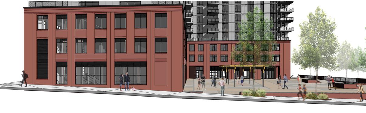
presentation drawings
south elevation perspective (raw render, linework export, and postproduction by self)
REF DW REF DW REF MW DW GENERAL NOTES KEYNOTES 1. REFER TO T0.01 FOR ADDITIONAL NOTES, SYMBOLS & ABBREVIATIONS. 2. REFER TO A5.10 FOR TYPICAL DEVICE MOUNTING AND INSTALLATION REQUIREMENTS. 3. REFER TO A7 SERIES SHEETS FOR TYPICAL FIRE RESISTANCE RATED WALL, FLOOR & CEILING ASSEMBLIES. 4. REFER TO A5.12 AND A5.13 FOR TYPICAL UNIT CABINET SECTION DETAILS. 5. REFER TO A5.14 AND 5.15 FOR TYPICAL TYPE A UNIT CABINET SECTION DETAILS. 6. REFER TO T1.00 & A7.50 FOR INTERIOR FINISHES, ACCESSORIES, APPLIANCES, PLUMBING & LIGHTING SCHEDULES. 7. REFER TO A7.10 & A7.11 FOR DOOR & HARDWARE SCHEDULES. 8. REFER TO A5 SERIES FOR FLOOR FINISH TRANSITION DETAILS. 9. ALL INTERIOR PARTITIONS ARE TYPE-1A U.N.O. REFER TO SHEET A7.00 FOR ADDITIONAL NOTES & PARTITION INFORMATION. 10. ALL COLUMNS WITHIN PERIMETER WALLS TO RECEIVE TYPE-9 FURROUT, U.N.O. 11. WHERE WALLS OF DIFFERENT TYPES ARE SHOWN TO ALIGN IN PLAN, ALIGN FINISHED FACE OF WALLS. 12. DIMENSIONS INDICATED ARE FROM FINISHED FACE TO FINISH FACE, U.N.O. 13. ALL UNIT ENTRY DOORS TO BE INSTALLED TO PROVIDE 18" MIN. CLEAR ON PULL SIDE OF DOOR, MEASURED FROM THE LATCH OF DOOR TO THE BASE BOARD OF THE NEAREST PERPENDICULAR WALL. PROVIDE A 60" X 60" CLEAR BETWEEN WALL BASES. NOTIFY ARCHITECT OF ANY DISCREPANCIES IN THE FIELD. 14. INTERIOR DOOR INSIDE FACE OF HINGE-SIDE JAMB SHALL BE 6" FROM FACE OF ADJACENT INTERSECTING PARTITION, U.N.O. 15. DOORS WITHIN DWELLING UNITS SHALL PROVIDE 31 5/8" MINIMUM NET FULLY OPEN CLEAR WIDTH, INCLUDING DOORS FOR PASSAGE, SHOWERS, & CLOSETS WHERE ACCESS DEPTH GREATER THAN 24". 16. BALCONY DOOR THRESHOLDS NOT TO EXCEED MAX 3/4" HIGH ABOVE THE INTERIOR FINISH FLOOR MATERIAL SURFACE, WITH 1/2" HIGH BEVEL STRIP HAVING TOP 1/4" HAVING 1:2 OR SHALLOWER SLOPE. 17. INSTALL FRAMELESS GLASS DOORS AT EACH BATHROOM SHOWER, TYP. REFER TO SPECIFICATIONS FOR INFORMATION. 18. SHOWER STALLS TO HAVE SCHLUTER-KERDI-LINE LOW PROFILE LINEAR DRAIN OR EQUAL. REFER TO A5.16. 19. PROVIDE CONCEALED FIRE-TREATED BLOCKING OR STEEL STRAPPING AS REQUIRED INSIDE PARTITIONS FOR MOUNTED EQUIPMENT, FIXTURES, & MILLWORK, AND AT GRAB BAR/SHOWER SEAT LOCATIONS IN ALL TYPE "A" & "B" DWELLING UNITS. REFER TO A5.11 FOR TYPICAL GRAB BAR/SHOWER SEAT BLOCKING DIAGRAMS. 20. ALL EXPOSED CONCRETE CEILINGS TO RECEIVE SKIM COAT WITH PAINTED FINISH U.N.O. REFER TO UNIT ENLARGED RCP'S FOR ELEVATION HEIGHTS. 21. ALL SUSPENDED CEILINGS TO BE PAINTED GWB, U.N.O. 22. SUSPENDED CEILING HEIGHTS MEASURED FROM TOP OF FLOOR STRUCTURE. CEILING HEIGHTS IN DWELLING UNITS, U.N.O.: A. DWELLING UNIT BATHROOM: 8'-0" B. DWELLING UNIT GWB: 8'-0" 23. ALL WASHER/DRYER CLOSETS OCCURRING BENEATH SUPPLY DUCTWORK SHALL HAVE SUSPENDED GWB CEILING. REFER TO MECHANICAL DRAWINGS FOR DUCT LOCATIONS. 24. REVIEW ACCESS PANEL LOCATIONS WITH ARCHITECT PRIOR TO LOCATION & INSTALLATION OF ITEMS REQUIRING ACCESS. 25. SKIM COAT & PAINT ALL EXPOSED COLUMNS. 26. LOCATE JUNCTION BOXES FOR FANS AT CENTER OF ROOM, U.N.O. 27. LOCATE LIGHT FIXTURES AT CENTER OF WALK-IN CLOSETS, U.N.O. 28. INCLUDE (2) USB OUTLETS AT KITCHEN & (1) PER BEDROOM. COORDINATE FINAL LOCATION WITH ARCHITECT. 29. ALL KITCHEN OUTLETS TO BE INSTALLED IN HORIZONTAL DIRECTION, U.N.O. 30. VERIFY WITH ARCHITECT RECEPTACLES & COVER PLATE FINISHES PRIOR TO INSTALLATION. 31. VERIFY WITH ARCHITECT LIGHT SWITCHES & COVER PLATE FINISHES PRIOR TO INSTALLATION. 32. ELECTRICAL INFORMATION SHOWN FOR REFERENCE ONLY, REFER TO ELECTRICAL DRAWINGS. NOTIFY ARCHITECT OF ANY DISCREPANCIES BETWEEN ARCHITECTURAL AND ENGINEERING DRAWINGS PRIOR TO IMPLEMENTATION. 33. WALK-IN CLOSETS SHALL HAVE (2) LEVELS OF SHELF & ROD LONGEST WALL & (1) LEVEL ALONG THE OTHER WALLS SHOWN WITH SHELVING. COAT CLOSETS SHALL HAVE (1) LEVEL OF SHELF AND ROD. 34. WALL, CEILING, DOOR AND TRIM SURFACES TO BE PAINTED, U.N.O REFER TO FINISH SCHEDULE. 35. ALL EXTERIOR WINDOWS TO RECEIVE ROLLER SHADES OR MINI BLINDS. REFER TO FINISH SCHEDULE. 36. FLOOR FINISH TRANSITION TO OCCUR AT CENTERLINE OF DOOR IN CLOSED POSITION, U.N.O. 37. SCHEDULED FINISH FLOOR TO BE INSTALLED UNDER ALL REFRIGERATORS, DISHWASHERS, RANGES, AND BATHROOM VANITIES. 38. DWELLING UNIT FURNITURE N.I.C. SHOWN FOR REFERENCE ONLY LEGEND TYPE A UNIT PER ANSI 117.1 2009 1 2 F 9C 1A 1A 9C 1A 9C 9C 9C 1A 1A 2 1A 9B 9B 9A BALCONY LIVING DINING BATHROOM 2 FOYER DEN BATHROOM BEDROOM CLOSET 4'-5 1/4" 1B 1B D100 D102 D107 D104 D103 D102 D101 D111 3'-9 1/4" 4'-1 7/8" 9'-6 3/8" 7'-10 1/4" 2'-3 1/8" 4'-5 3/8" 3'-6 7/8" 4'-0 3/8" 2'-7 1/4" 5'-5 5/8" F UW1 UT4 UT4 UW1 UW1 F UV2 UK1 UK1 UK1 US UC US UB UK3 UK5 UK5 UK5 UK3 UK2 UT 8'-0" 8'-0" 8'-0" UH UH UE1 UW2 UW2 US1 UE2 UE4b A5.12 SIM 4 A5.12 UT1 UW2 UW2 UE6a US1 UF1 7 SIM 2 SIM UT1 RECOMMENDED WINE UW2 US1 A5.13 SIM A5.12 SIM US1 US1 US1 UWB2 US2 UF8 UF3 UF13 UP4 US2 UV2 UW3 UT3 UF8 UT3 UT3 UF4 UF4 UWB2 UF8 UT3 UF8 UT3 UF6 UF6 UF9 US2 UF3 UF13 UV2 UW3 US2 UWB2 UT3 STRUCTURAL ENGINEERING 3222 N ST NW SUITE 500 Washington, DC 20007 f 202.600.7280 info@r2l‐architects.com 12435 Park Potomac Ave. Suite 300 Potomac, MD 20854 SMISLOVA, KEHNEMUI & ASSOCIATES, PA CIVIL ENGINEERING LANDSCAPE ARCHITECT 11600 Ninth St. N St. Petersburg, FL 33716 t 727‐210‐0492 POWER DESIGN, INC. Charlottesville, VA 22903 t 434‐295‐5624 TIMMONS GROUP ELECTRICAL ENGINEERING ENVELOPE CONSULTANT 1828 L St. NW Suite 950 Washington, DC 20036 t 202‐239‐4199 SIMPSON GUMPERTZ & HEGER CODE CONSULTANT Ashburn, VA 20147 t 703‐481‐2000 f 703‐437‐6432 IBTS ACCESSIBILITY CONSULTANT 10309 Rosser Rd Dallas, TX 75229 pete@skarzenski.com 608 Preston Avenue Suite 200 Charlottesville, VA 22903 11600 Ninth St. N St. Petersburg, FL 33716 t 727‐210‐0492 POWER DESIGN, INC. 200 2nd St SW Charlottesville, VA 22902 Market Plaza, LLC Charlottesville, VA 22903 UNIT T14 (UNIT T16 SIM) ENLARGED UNIT PLANS A4.08 SCALE: 1/4" 1'-0" 1 UNIT T14 (UNIT T16 SIM) -ENLARGED FLOOR PLAN T02 T01 T04 T06 T08 T10 T05 T07 T15 T16 T12 SCALE: 1/4" = 1'-0" 2 UNIT T14 (UNIT T16 SIM) -ENLARGED FINISH FLOOR PLAN SCALE: 1/4" 1'-0" 3 UNIT T14 (UNIT T16 SIM) -ENLARGED REFLECTED CEILING PLAN 3/8" 1'-0" 4 KITCHEN ELEVATION A 3/8" 1'-0" 5 KITCHEN ELEVATION B 3/8" = 1'-0" 6 ISLAND ELEVATION A 3/8" 1'-0" 7 ISLAND ELEVATION B SCALE: 3/8" = 1'-0" 8 ISLAND ELEVATION C SCALE: 3/8" 1'-0" 9 ISLAND ELEVATION D 3/8" 1'-0" 10 BATHROOM 1 ELEVATION NORTH 3/8" 1'-0" 11 BATHROOM 1 ELEVATION EAST 3/8" 1'-0" 12 BATHROOM 1 ELEVATION SOUTH 3/8" = 1'-0" 13 BATHROOM ELEVATION WEST SCALE: 14 BATHROOM 2 ELEVATION NORTH SCALE: 15 BATHROOM 2 ELEVATION EAST SCALE: 16 BATHROOM ELEVATION SOUTH SCALE: 17 BATHROOM 2 ELEVATION WEST
construction documents
typical brick details (initial drafting, sheet set-up and major drawing edits by self)
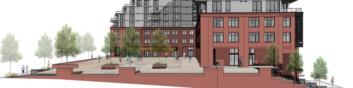
presentation drawings
east elevation perspective (raw render and linework export by self, post-production by other with input by self)
4 STEEL STUD FRAMING SELF ADHERED FLASHING; ADHERE TO DRIP EDGE MORTAR CATCHMENT SYSTEM GALVANIZED SHELF ANGLE, STAINLESS STEEL FLASHING WITH STEPPED & CONCRETE FLOOR SLAB R U W G B CAVITY WEEP & VENT INSERT SEALANT JOINT 4" STEEL STUD FRAMING SKIM COAT PAINT EXPOSED SLAB FROM EDGE OF S.S. DRIP EDGE WEDGE ANCHOR BOLT, SEE STRUCTURAL DWGS TERMINATION BAR & SEALANT; SECURE TO STUDS MEMBRANE PATCH @ CONT. AIR BARRIER PENETRATIONS, TYP. FLOOR BTM.O.S BTM.O.S WINDOW AS SCHEDULED SCHEDULED BRICK SOLDIER COURSE BRICK JAMB BEYOND TERMINATION BAR & SEALANT INTERIOR FINISHES BY LIPPED BRICK SOLID SURFACE APRON (REFER TO INTERIORS DWGS) (REFER TO INTERIORS DWGS) WINDOW INTERIOR AIR SEAL SILL WITH SELF-ADHERED MEMBRANE TURNED UP, INCLUDING END DAMS BEYOND, CONTINUOUS BLOCKING BRICK JAMB BEYOND MORTAR CATCHMENT SYSTEM PAINTABLE SEALANT 1'-0 1/4" FASTENER SEE A7.05 FOR TYP. NOTES. BELLOWS IN AIR WATER BARRIER SYSTEM TO ALLOW FOR MOVEMENT STRUCTURAL STEEL AS REQ'D IN CAVITY. SEE STRUCTURAL GALVANIZED LOOSE LINTEL, SEE TO STRUCTURAL DRAWINGS FOR SIZING. PAINT UNDERSIDES TO MATCH WINDOW SYSTEM, TYP. 1 1/4" INTERIOR FINISH, INSTALLED DURING FUTURE TENANT FITOUT OFFICE OFFICE WOOD BLOCKING - INSTALL BEFORESILL FLASHING A8.20 SIM 0'-0 1/2" WINDOW RAINSCREEN SEAL WINDOW PRIMARY SEAL WINDOW HEAD RECEPTOR WINDOW JAMB BEYOND SCHEDULED BRICK VENEER AIR WATER BARRIER SYSTEM 2 THICK MINERAL WOOL INSULATION; R-7.5 MIN. FRICTION FIT INSULATION PANELS BETWEEN SELF-ADHERED MEMBRANE FLASHING, WRAP INTO OPENING PER MANUFACTURER'S REQUIREMENTS SCHEDULED SLOPED BRICK SILL, BELOW FIBERGLASS BATT INSULATION; -13 MIN. INTERIOR FINISH, INSTALLED DURING FUTURE TENANT FITOUT V-STRUCK MORTAR JOINT, TYP. 3WINDOW RAINSCREEN SEAL WINDOW PRIMARY SEAL STOOL BELOW COMPRESSIBLE FILLER STRIP WINDOW SILL RECEPTOR BELOW SHIM AS REQUIRED SELF-ADHERED MEMBRANE STRUCTURAL ENGINEERING 3222 N ST NW SUITE 500 Washington, DC 20007 f 202.600.7280 info@r2l‐architects.com 12435 Park Potomac Ave. Suite 300 Potomac, MD 20854 SMISLOVA, KEHNEMUI & ASSOCIATES, PA CIVIL ENGINEERING LANDSCAPE ARCHITECT 11600 Ninth St. N St. Petersburg, FL 33716 t 727‐210‐0492 POWER DESIGN, INC. Charlottesville, VA 22903 t 434‐295‐5624 TIMMONS GROUP ELECTRICAL ENGINEERING ENVELOPE CONSULTANT 1828 L St. NW Suite 950 Washington, DC 20036 t 202‐239‐4199 SIMPSON GUMPERTZ & HEGER CODE CONSULTANT Ashburn, VA 20147 t 703‐481‐2000 f 703‐437‐6432 IBTS ACCESSIBILITY CONSULTANT 10309 Rosser Rd Dallas, TX 75229 pete@skarzenski.com 608 Preston Avenue Suite 200 Charlottesville, VA 22903 11600 Ninth St. N St. Petersburg, FL 33716 t 727‐210‐0492 POWER DESIGN, INC. 200 2nd St SW Charlottesville, VA 22902 Market Plaza, LLC Charlottesville, VA 22903 TYP. EXTERIOR DETAILSMASONRY A8.20 SCALE: 3" 1'-0" 1 TYPICAL MASONRY WINDOW HEAD AND SILL SCALE: 3" 1'-0" 2 TYPICAL MASONRY WINDOW JAMB SCALE: 6" 1'-0" 3 TYPICAL AIR WATER BARRIER BELLOWS
35
PRIVATE RESIDENCE
Bethesda, MD Barnes Vanze Architects role: Primary Staff programs used: SketchUp and AutoCAD
I started on this project relatively early, just after initial plans and elevations of the house had been approved by the client. As I was the only other staff member on this project, I was able to work one-on-one with the project manager. I drafted and produced almost every drawing used in client or consultant meetings and drawing sets.
The project focused on the demolition of an existing house and construction of a new residence for a family of eight with an in-law wing, play court, media room, formal dining room, informal family room and attached porch, and three story feature stair.
I learned the most on the project working on building and walls section, and associated details. Meeting with and coordinating drawings with the structural engineer was also an important step in my understanding of the design process.
I particularly enjoyed modeling the house and its interior in Sketchup, producing various images such as the one to the right, to show the client. Being able to see the clients’ joy and interest as I navigated around the model to show them their future home was especially exciting.
36
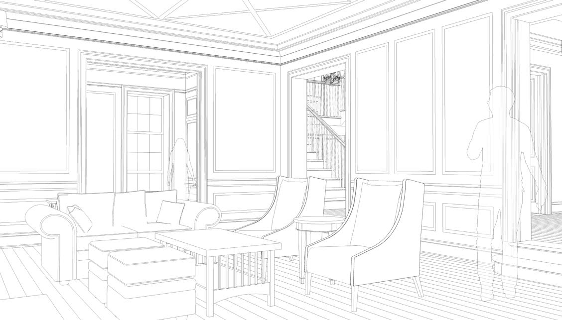 Interior view of living room (by self).
construction documents
first floor plan (inital drawing by project manager, major edits by self)
presentation drawings
interior
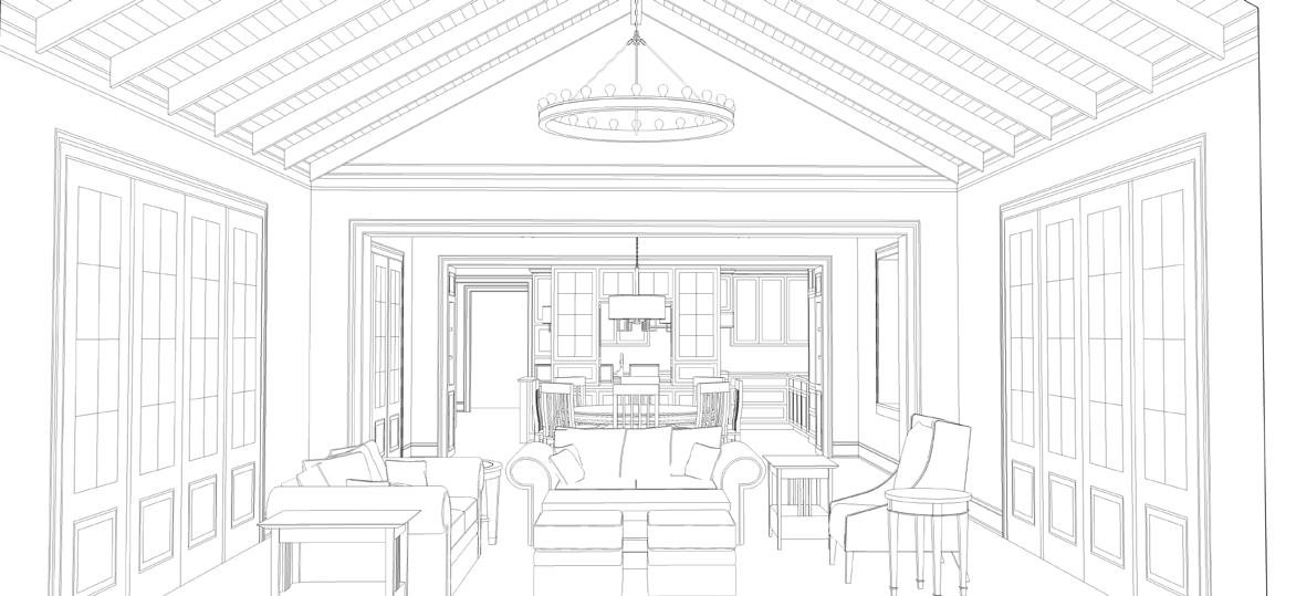 view of family room (model and view by self)
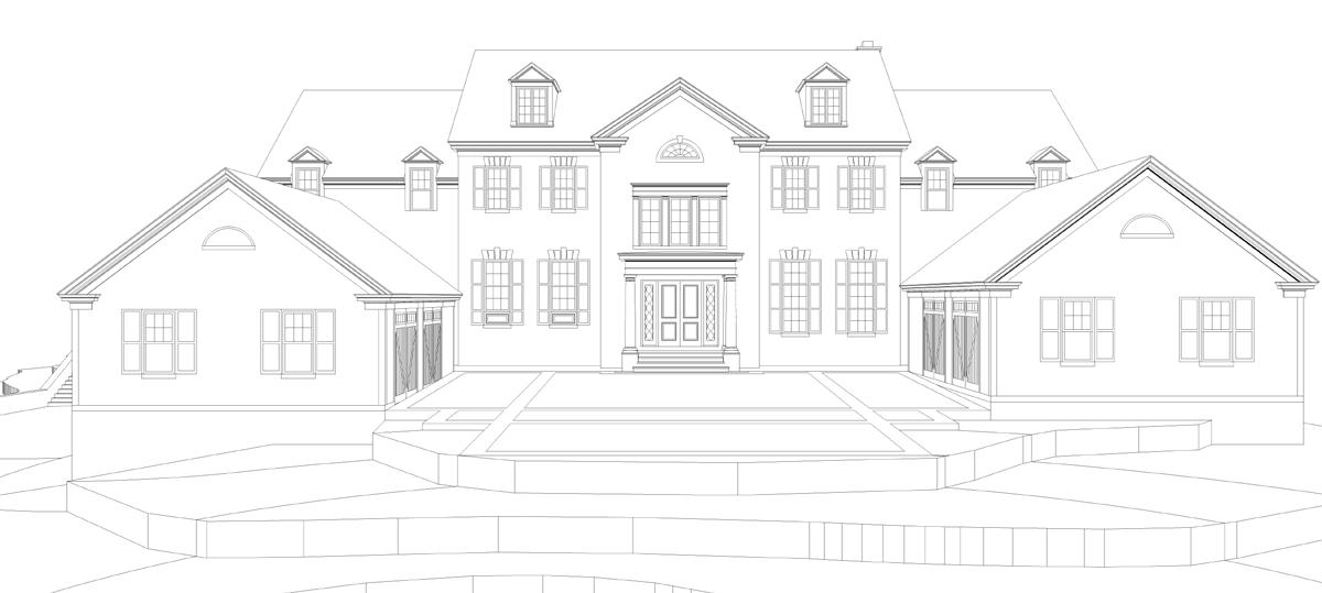
exterior elevations (inital drawing by project manager, major edits by self)
presentation drawings
exterior view of front of house (model and view by self)
construction documents
39
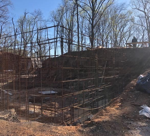
construction documents building sections (by self)
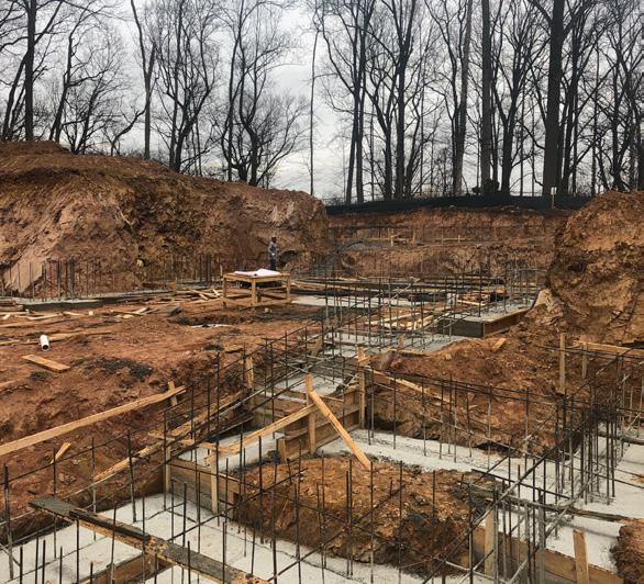
construction photographs (by project manager)
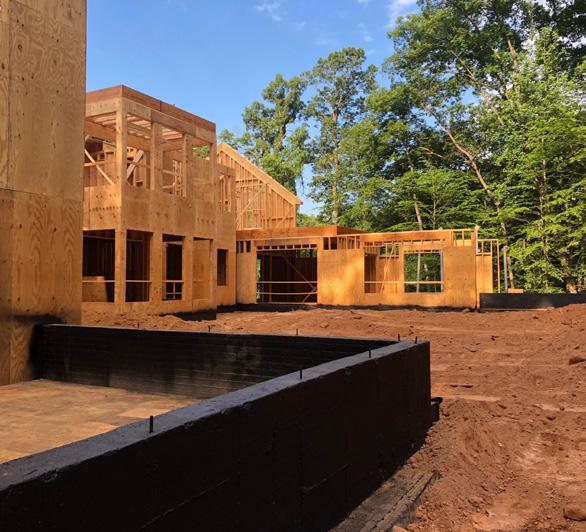
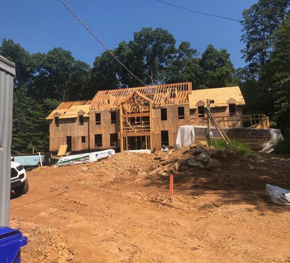
construction documents
wall sections (by self)
41
construction photographs (by project manager)
FEATURE STAIRS
Henlopen Acres, DE | Georgetown, DC Barnes Vanze Architects role: Secondary Staff programs used: SketchUp, Rhinoceros 5.0, AutoCAD
While my role on both of these projects was somewhat limited to helping out as needed and editing already drafted drawings, I had the chance to explore issues relating to the detailing of the feature stairs of both residences.
On the left is a more contemporary, steel staircase for a beach house located in Henlopen Acres, Delaware. A digital model produced in Sketchup was used to study the intersections of the c-channel stringers at each corner and how that intersection interacted with the railing post above. Various options were explored including a completely open corner, one that included welded pieces at the flanges but left the web open, and a boxed-off corner. Ultimately, the corners were boxed off with additional welded pieces, creating a strong, assertive corner that appears to hold the railing post quite nicely and transitions from the lower stringers to the upper one.
On the right in a more classical, marble staircase for a weekend house located in Georgetown, DC. The stair is interesting in that it is supported on one side by the marble stringer and the other by a concrete wall. I was tasked with modeling the staircase in the firm’s go-to program, Sketchup, in order to provide initial drawings to the fabricator who would be producing the marble stringer and treads. Initially, I struggled to model the staircase in Sketchup, downloading plug-in after plug-in, only to fail at achieving the proper geometry of treads that had a different curve at the front than at the back and were also tapered in section. I knew I could model it more easily in Rhino and eventually convinced the project manager and principals to let me use my personal computer to do so. The task was then quickly achieved with a number of 2-rail sweeps to produce the exported image on page 39. Linework was then exported from this model and sent to the fabricator.
42
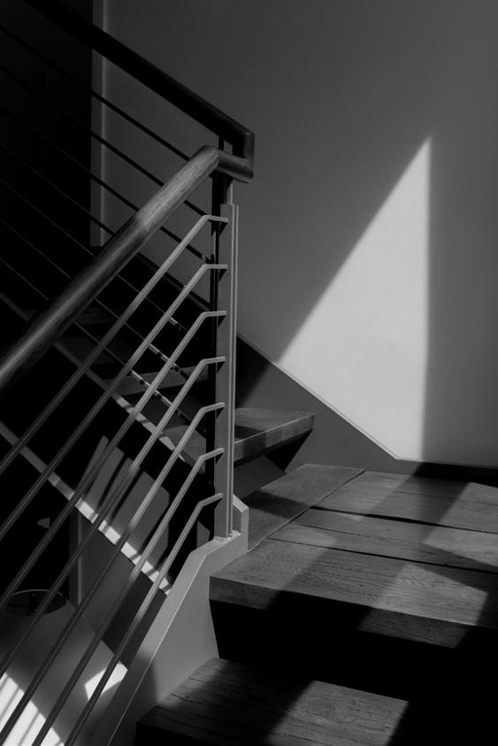
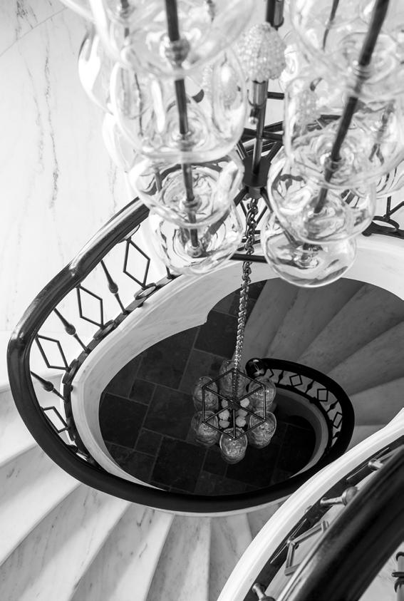 Detail photographs of feature stairs (by professional photographer).
project images
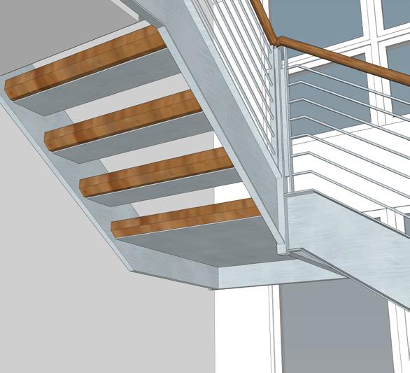
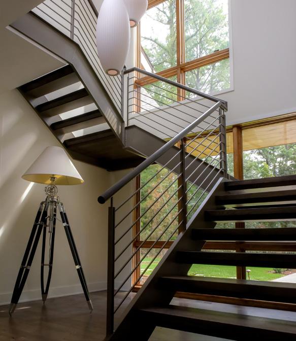 top left: process digital model (model and drawing by self); top right: professional photograph (by project photographer); bottom: construction document stair detail sheet (initial drawing by project manager, major edits by self)
project images
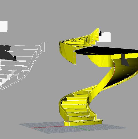
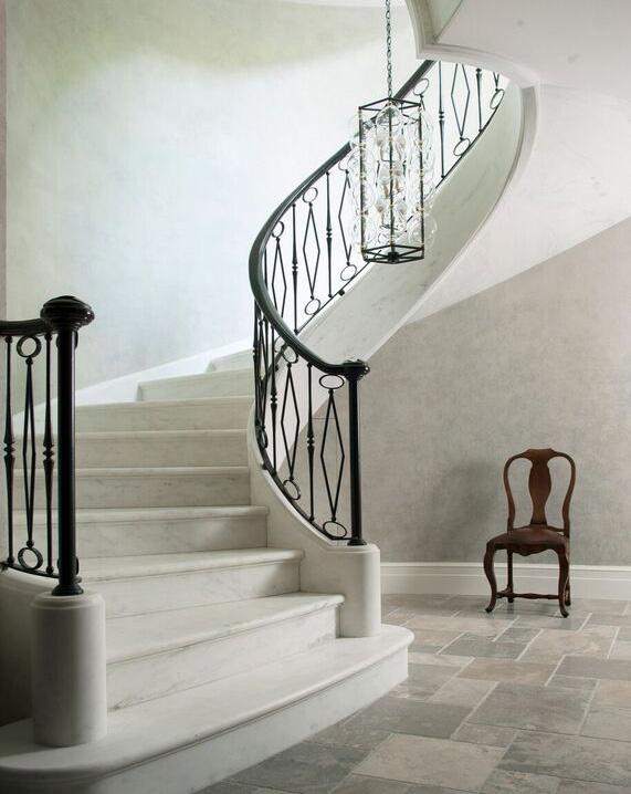 top: construction document stair detail sheet (drawing by others)
bottom left: process digital model (model and drawing by self);
45
bottom right: professional photograph (by professional photographer)
DIGITAL CRAFT - SCRIBBLED BRICK
SCRIBBLED BRICK
Clemson, SC - Fall 2016 critic: Douglas Hecker time: 6 weeks programs used: Rhinoceros 5.0, Cura, and Potterbot
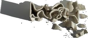
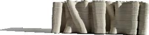
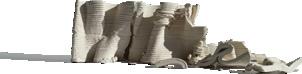
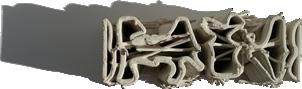
Tasked with the goal of rethinking the brick, I began my studies by testing the capabilities of the clay potterbot. I was interested to see how far I could push the technology and material and still produce a successful brick. I tried to produce intentional failures that would allow light to penetrate though the brick. However, the potterbot worked better than I expected and produced both of the “disintegrated bricks”. Next, I tried to see how steep of a slope i could print in clay, producing the “stressed brick”. Then, I designed and printed a brick with long sides that were made of ribbons of material. I alternated concave, straight, and convex ribbons hoping that the gaps between them would produce the light penetration I was seeking. However, the material drooped during the printing process and produced a much more interesting effect than I expected: a “woven brick”.
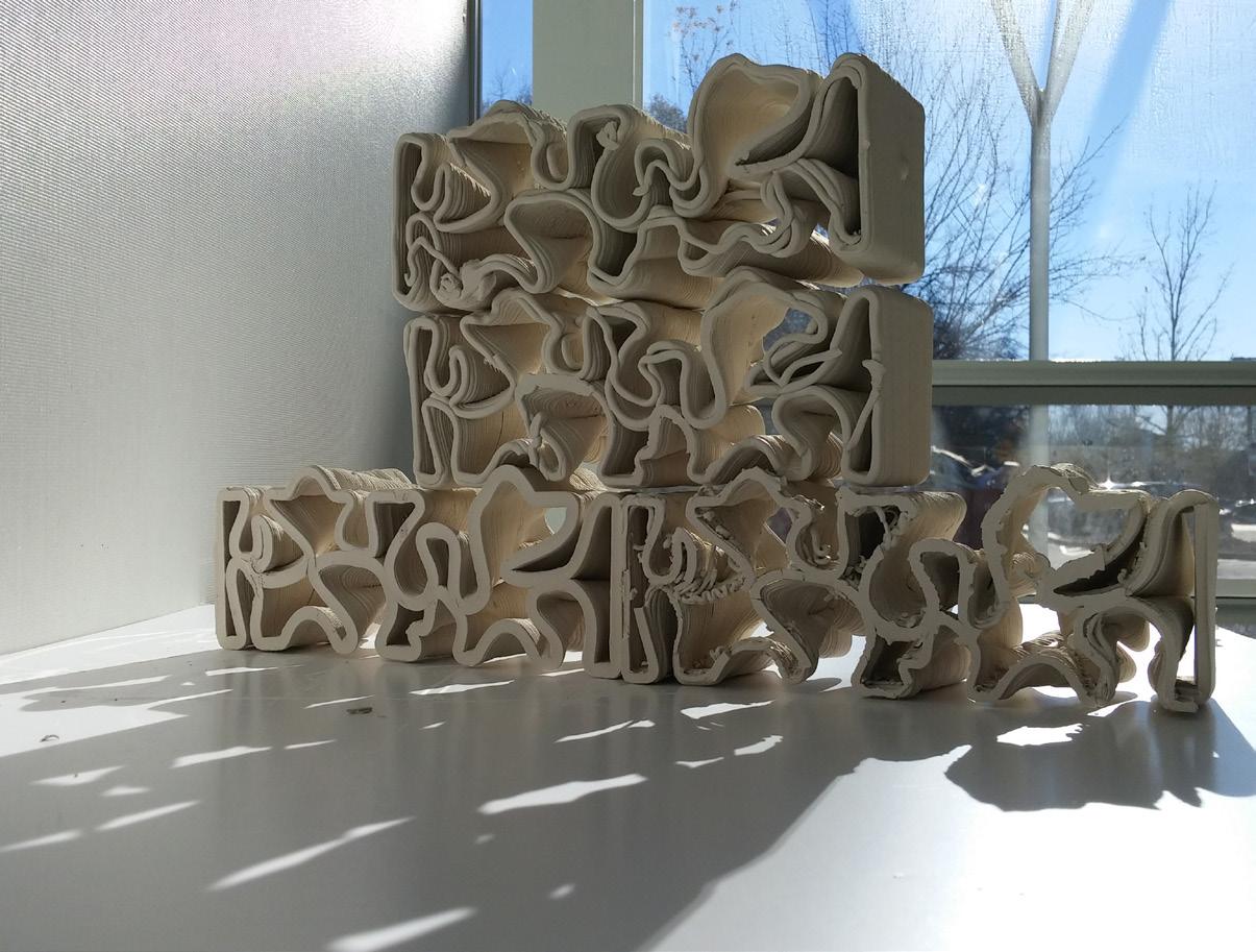
My first true success came when I designed a brick whose long sides had been scribbled somewhat randomly. These scribbled surfaces occasionally intersected one another and produced the “scribbled brick 1”. I tried to increase the number and complexity of the scribbles making up each long face, resulting in the failed bricks 2 through 5. The potterbot was simply unable to print in a continuous path due to the complexity of the surface. As a result, it moved around discontinuously and printed clay in strands where I did not want it. With “scribbled brick 6”, I returned to the success of the first scribbled brick, but contained the brick in a 3-inch by 3-inch by 9-inch volume to allow for stacking and the creation of a wall.
The addition of notches along the long sides of the brick in “scribbled brick 8” allows for either stacked to staggered arrangements. In the final wall assembly photos, both arrangements are shown. The interacting long sides of the brick create structural infill, allowing for an otherwise hollow brick. The holes in the brick allow for the light penetration I had sought after from the beginning.
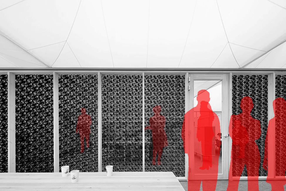
Ideally, this brick would be used to construct interior wall partitions in office settings or create interesting museum installations. They are also lighter than typical bricks and arguably more visually interesting.
48
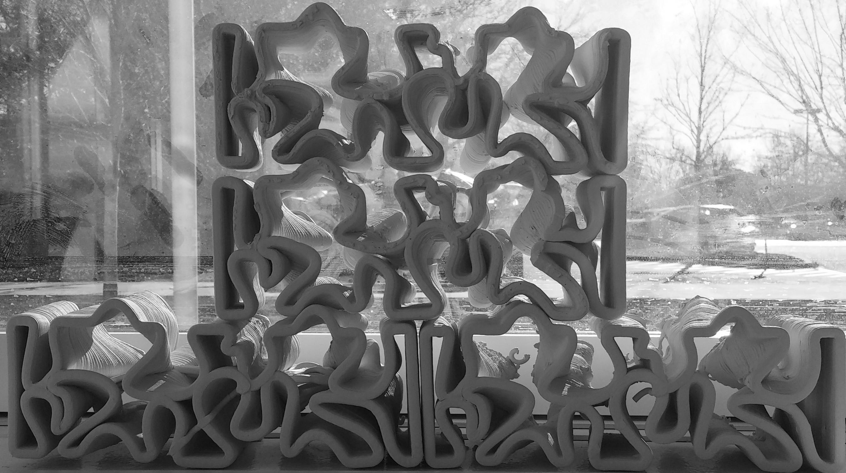 Detail of scribbled wall
brick prototypes
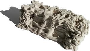
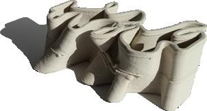
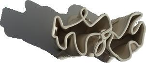
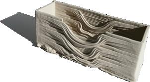
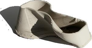
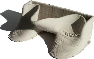
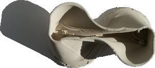
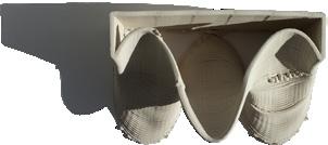
top to bottom: disintegrated brick 1; disintegrated brick 2; stressed brick; woven brick; scribbled brick 1 ; scribbled brick 2
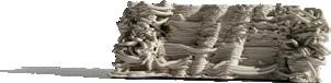
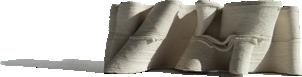
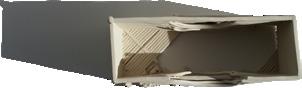
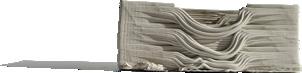
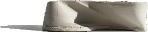
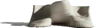
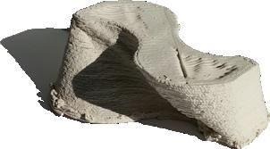
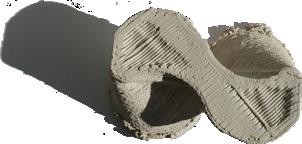
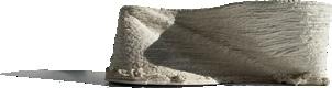
brick prototypes
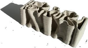
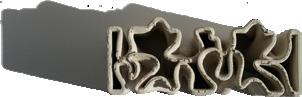
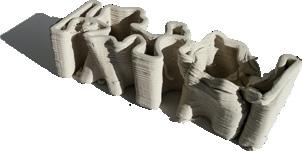
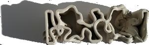
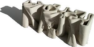
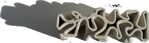
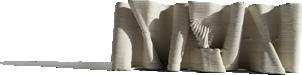
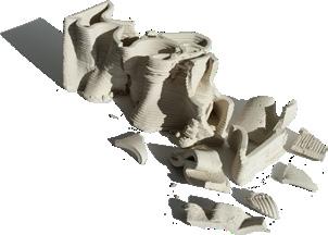
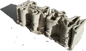
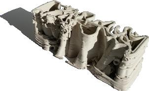
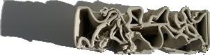
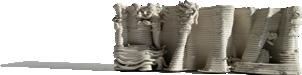
scribbled brick 3; scribbled brick 4; scribbled brick 5; scribbled brick 6 ; scribbled brick 7; scribbled brick 8

51
brick process
top: process
bottom: interior office application
9” 3” 3” FLAT NODE
TRANSLATE
SWEEP 2
MIRROR
increased surface area increases sound absorption
voids allow for light to penetrate brick and view through
notches allow for easy stacking
scribbled infill creates structural integrity
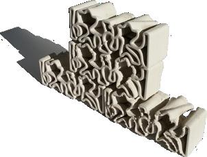

final scribbled brick wall 53
ACADEMIC WORK
GRADUATE WORK
SHIFT and SUBVERT
Barcelona, Spain - Spring 2016
critic: Toni Montes time: 12 weeks
programs used: SketchUp and Podium, AutoCAD, Photoshop, Illustrator, InDesign
The title and concept of this project were inspired by the notion of the government of Barcelona returning the area of Can Batlló to the citizens and allowing them to organize and govern it and themselves. This notion, representing a subversive paradigm shift, appears in the building as a series of ramps that shift and subvert around other ramps and programmed spaces. The primary ramp descends through the building, creating an interior pedestrian passage and navigating an existing topography change between the east and west facades. It connects Can Batlló to the nearby metro station and larger metropolitan area. Program then fell into one of three realms: that of the topography below, that of the modular structure above, or that which connects the two. Larger and more public program, such as the workshop and multi-use high space, belong to the topography while smaller and more private program, such as the offices and classrooms, belong to the structure. The civic platform and combined gallery and library connect the two previously mentioned realms and allow the visitors to interact with the citizens.
Each of the programmatic elements contains an educational component, aimed to educate the citizens at a variety of scales, in order to teach the community how to thrive independently of the government. For example, children can learn typical subjects in the classrooms while adults learn to grow food in the greenhouses and students research in the library.
58
physical, sectional model showing the relationships between the major programmatic spaces
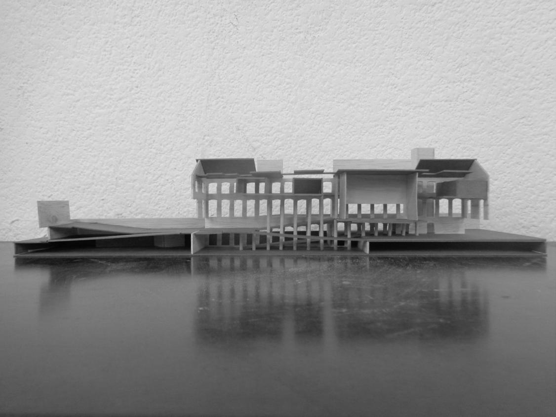
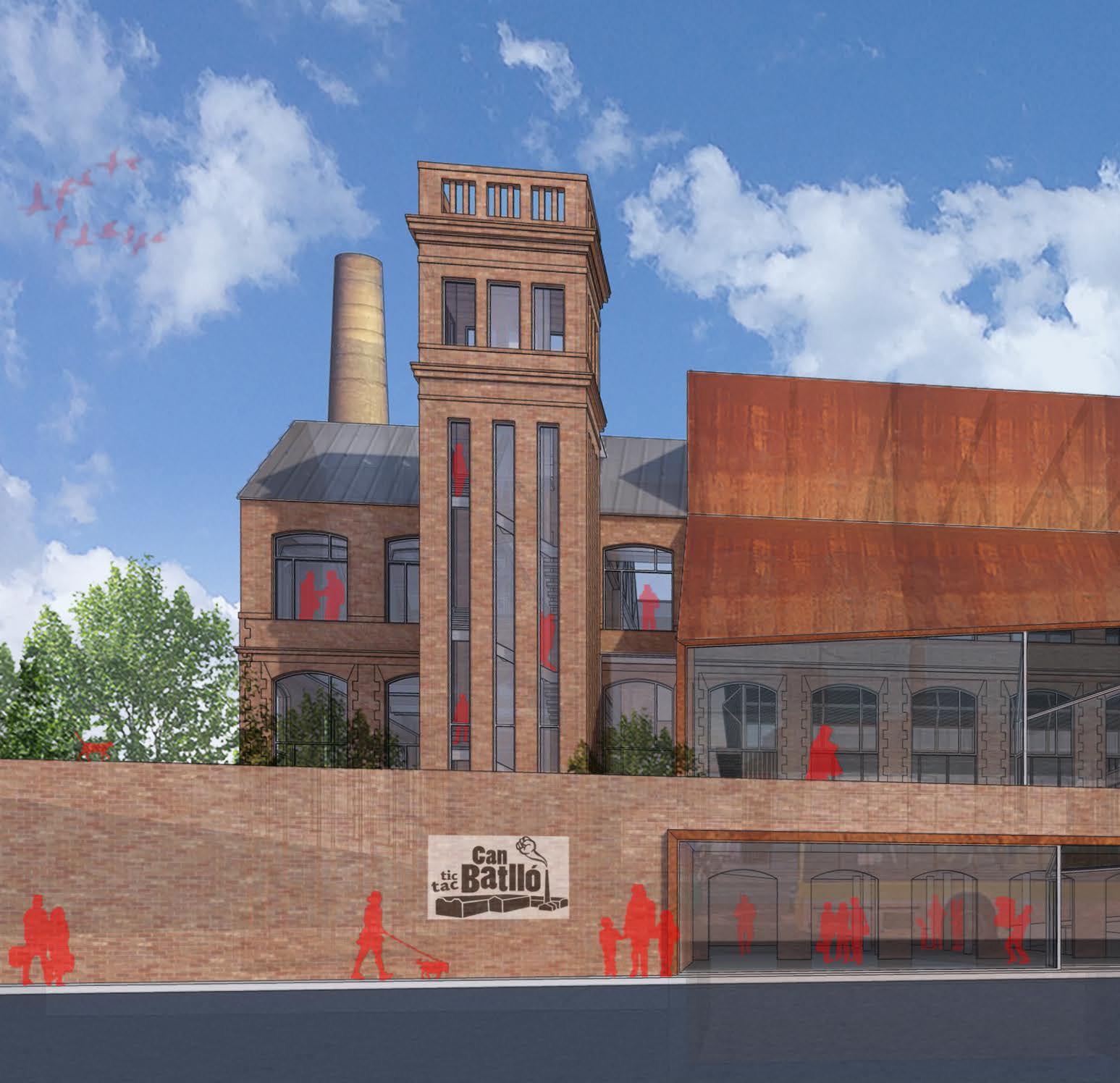
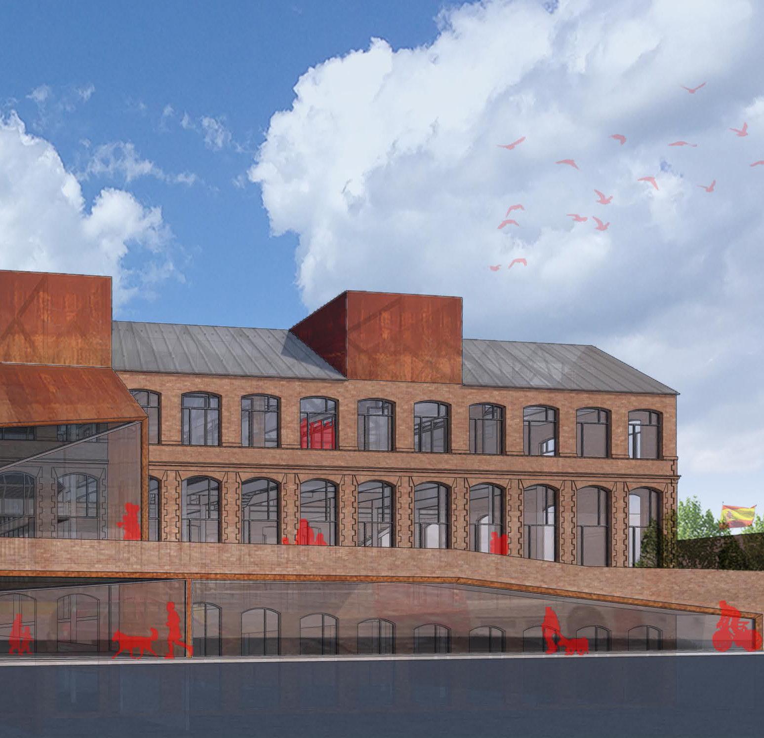
exterior view 61
south facade as seen from the Gran Via, including cafe and user shop space
top: site section bottom: site plan
A tall masonry site wall prevents views into Can Batllo while walking along the Gran Via, driving by on the Gran Via, or approaching the site from the nearest metro station. Visitors can access the site through an opening in the south site wall or through an entrance at the northeast corner. This site wall creates a barrier that isolates Can Battlo from the rest of Barcelona.
proposed site strategy
top: site section bottom: site plan
This project focuses on connecting Can Batllo to the larger city area by puncturing an opening in the site wall and creating a main pedestrian ramp through the proposed civic center
Magòria-La Campana agòria-La Magòria-La Campana Magòria-La Campana
existing site
survey existing conditions
demolish select existing structures
create new upper public courtyard and renovate existing lower public courtyard
manage topography change with new interior pedestrian passage through building
excavate basement and ramp down to high-ceiling workshop space
ascend up to main civic space, hierarchically placed above pedestrian ramp
create civic platform by connecting main civic space to outdoor space on north side of building
extend civic platform through building with a cafe on the southern side, creating an open public facade
modify classroom and reading room roofs for access to indirect northern light
lift greenhouse roofs to allow for direct southern sun exposure
massing progression 63
start-ups/retail
Secondary ramps allow users to access a basement level workshop space, where citizens can learn to produce products on their own and sell them in the adjacent store space. Citizens can also use the tools in the workshop to build the wood frame window panels featured prominently throughout the building. The primary ramp subducts under the main public space, the civic platform, that penetrates the building in the north-south direction and connects a northern outdoor space to a new southern terrace. A small lobby, multi-use hall, and cafe comprise the interior promenade along the civic platform. An existing structural grid informed the placement of ramps and interior spaces.
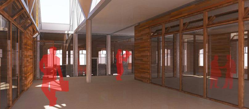
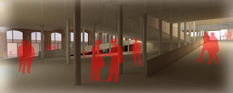
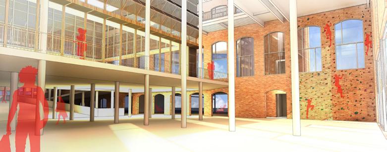
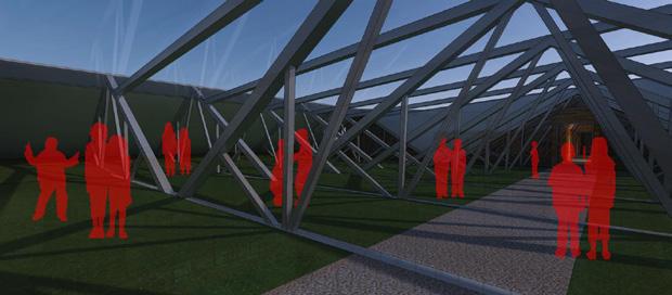
plans
left to right: ground floor; first floor; second floor; third floor
not shown: basement plan; roof plan
gallery lobby cafe
theater civic platform gallery
polivalent
interior views
clockwise: conference rooms; greenhouse; gallery; cafe; workshops; multi-use high space
offices
reading rooms
classrooms
library greenhouses conference rooms
The multi-use hall appears as an atypical space in which wood frame glass panels with attached louvers form the walls. Moveable partitions on the north and south walls allow the room to be completely open to facilitate movement through the building or completely closed to allow for a more traditonal venue for meetings and performances. Operable louvers create a variety of lighting conditions and views into the space, creating a dynamic space the reinforces the importance of the community.
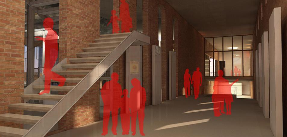
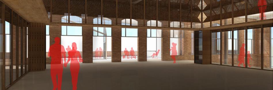
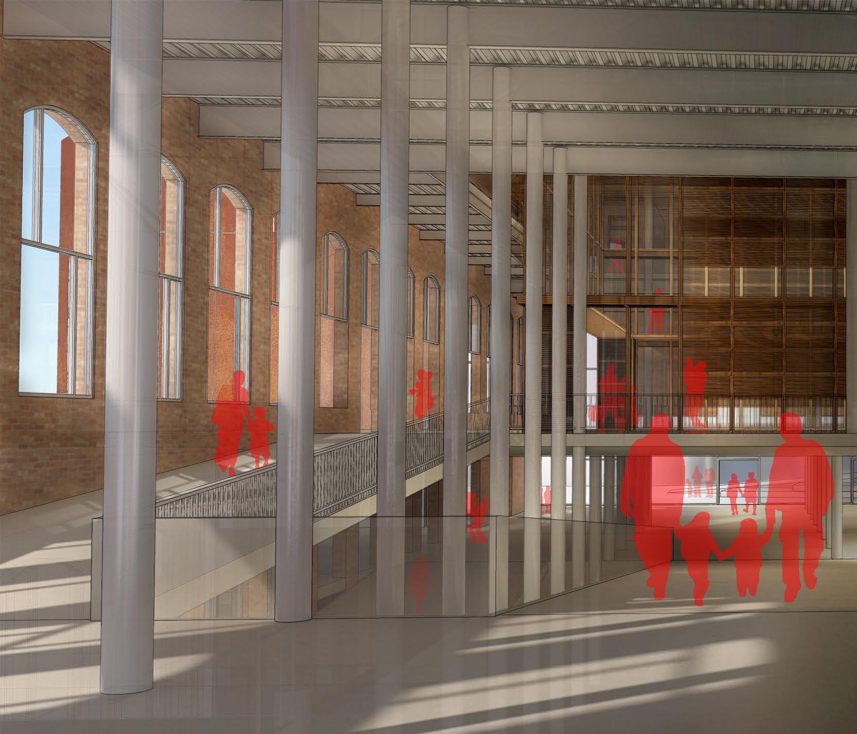
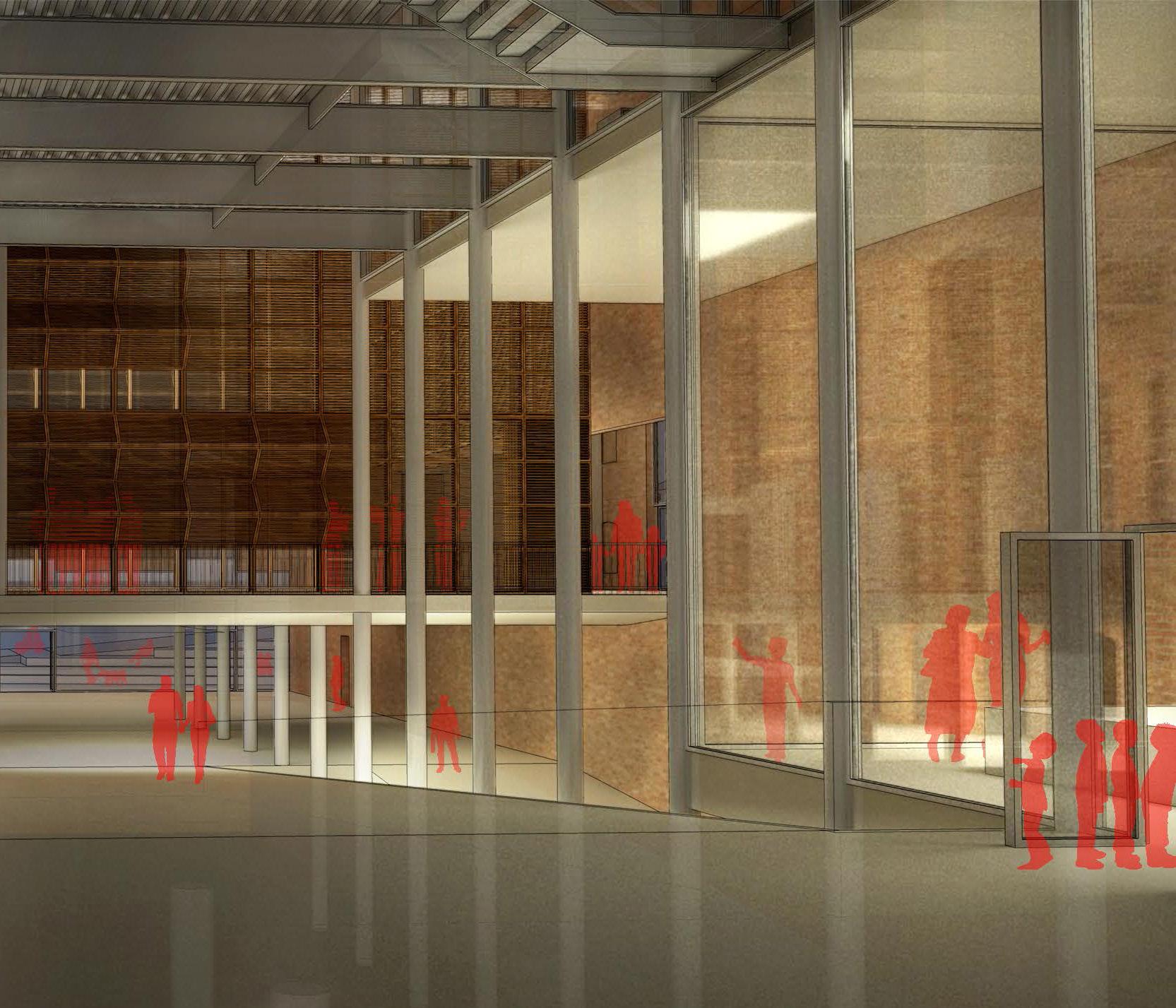
65
theater seating options
left to right: market; reception; concert; tribunal
Folding partitions comprise the north and south walls of the focal theater space on the civic platform. Changing these partitions allows for a variety of communal activities to occur on the platform.
North-south partitions open and lower louvers folded up. Natural light and views enter.
Operable doors in N-S partitions and half of the lower louvers folded up. Natural light enters and some views enter and exit.
Operable doors in south partition wall with optional back-of-house at north end. Little amounts of light and views enter.
interior view of main pedestrian ramp, theater, and civic platform
Operable doors in north-south partitions and half of the lower louvers folded up. Some natural light and views enter.
theater louver configurations
Louvers that fold up and down, together with wood-frame glass panels, make up the walls of the theater. These louvers allow for different views and amounts of light to enter and exit, based on the use of the theater space, depending on their position.
67
building sections
top: transverse section through lobby
bottom: longitudinal section through pedestrian ramp
section details
top left: new wood wall
top right: library wall panel and concrete floor
bottom left: theater wall panel and louver
bottom right: corten steel wall
3/4” wood sheathing wood joist with insulation
1/2” drywall new window in existing opening new window with operable upper portion new concrete floor new steel decking new steel structural beam
existing truss new concrete floor new steel decking new steel beam wall panel supports (tied into concrete slab) new wood frame glass wall panels louver supports new operable wood louvers louver track
new wood frame window panels new concrete floor new steel decking new steel beam (beyond) drop ceiling ties
3/4” wood sheathing 1/2” drywall ceiling new spandrel glass
existing roof 1” corten steel wall cap
1” corten steel wall panel
2” air gap moisture barrier
3/4” wood sheathing
2x6 metal stud with insulation
1/2” drywall
existing truss new glass infill panel new concrete floor new steel decking
THIRD FLOOR CEILING HEIGHT + 16,34 m THIRD FLOOR ELEVATION + 13,6 m THEATER CEILING HEIGHT + 13,39 m SECOND FLOOR CEILING HEIGHT + 12,94 m SECOND FLOOR ELEVATION + 9,89 m GALLERY CEILING HEIGHT + 8,75 m THEATER FLOOR ELEVATION + 3,59 m LOBBY & GALLERY FLOOR ELEVATION + 2,05 m LIBRARY FLOOR ELEVATION + 9,06 m WORKSHOP CEILING HEIGHT + 1,44 m LOW WORKSHOP CEILING HEIGHT - 0,61 m WORKSHOP FLOOR ELEVATION - 2,83 m
building sections
top: transverse section through civic platform
bottom:
environmental strategies section
climate information
left to right: sun path diagram; annual wind direction; design temperatures; conditioned spaces
roof transformations
clockwise: classrooms; greenhouse; solar chimney; reading room
N 14 12 10 8 6 4 2 0 S W E WNW ENE WSW ESE NW NE SW SE NNW NNE SSW SSE UNCONDITIONED 4403 m2 - 73.75% WORKSHOPS, STARTUPS, MULTI-USE HIGH SPACE, CAFE, CIVIC PLATORM, LOBBY, GREENHOUSES, STORAGE, MECHANICAL, CIRCULATION, and BATHROOMS. MULTI-USE THEATER GALLERY, LIBRARY, CONFERENCE ROOMS, OFFICES, CLASSROOMS, and READING ROOMS. CONDITIONED 1273 m2 - 21.25% SEMI-CONDITIONED 294 m2 - 5% TOTAL INTERIOR AREA 5970 m2 N S E W 30 150 330 210 60 06:18 21:28 18:52 07:16 17:25 08:14 120 300 240 10° 20° 30° 40° 50° 60° 70° 80° Summer So c e Equinoxes WinterSoltice GNIRPS NMUTUA W N T RE MMUS R 0°C 16°C 8°C 24°C 22°C 10°C 26°C 6°C 20°C 12°C 28°C 4°C 18°C 14°C 30°C 2°C IMESROIRETNIDNOC T NO E D TIDNOCROIRETNI DENO DNOCNUROIRETNI T I NO E D
69
modified roof classrooms learn to teach
new exterior walls greenhouse learn to grow reading rooms learn to research offices learn to administrate library learn to educate conference rooms learn to collaborate multi-use hall learn to govern and perform civic platform learn to engage cafe learn to interact gallery learn to display multi-use high space learn to exercise vertical circulation start-up stores learn to sell storage workshops learn to make
new program
existing and modified exterior walls
modified terrain
MODULAR STRUCTURE CONNECTIVE TISSUE REALMS TOPOGRAPHY
axonometric of building components
exterior views
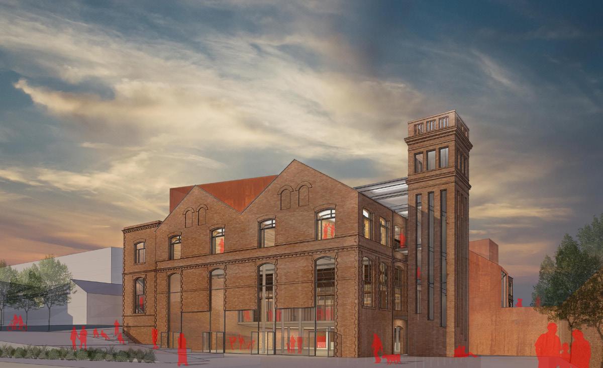
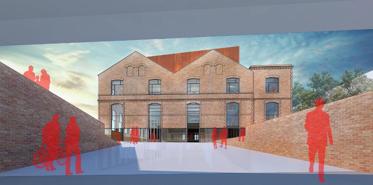 top: public entry to upper courtyard from metro station
71
bottom: Can Batllo entrance
CLEMSON BOAT HOUSE
Clemson, SC - Fall 2015
critic: Ufuk Ersoy, David Franco, and Ulrike Heine time: 5 weeks
programs used: Rhinoceros 5.0, Maxwell, AutoCAD, Photoshop, Illustrator, InDesign
This project is the first of three in a semester long project series aimed at “Rethinking Clemson”. Seeking to fulfill a need of the city of Clemson, we were tasked with designing a new community boat house. My initial inspiration came from the shape and direction of a rowing shell itself. I arranged three types of program (cultural, residential, and private) in this form. The building itself protrudes from the terrain as if moving away from it, similar to how rowing shells begin races.
The challenge of moving rowing shells from the parking lot to the boat storage bay provided me a unique design challenge. I solved this challenge by piercing the building with a ramp that would allow rowers to move the shells from up above to down below, moving through the building. In this way, the act of a team moving the boat together as one become a public spectacle. Cultural facilities, such as a gallery, library and race viewing platform, are placed on the upper level. Facilities to allow for the long-term stay of rowing teams, such as bedrooms, a gym, and a lounge, occur in the middle of the building. Finally, the lowest level is dedicated to the boat bay and storage as the rowing shells need direct access to the docks and water.
72
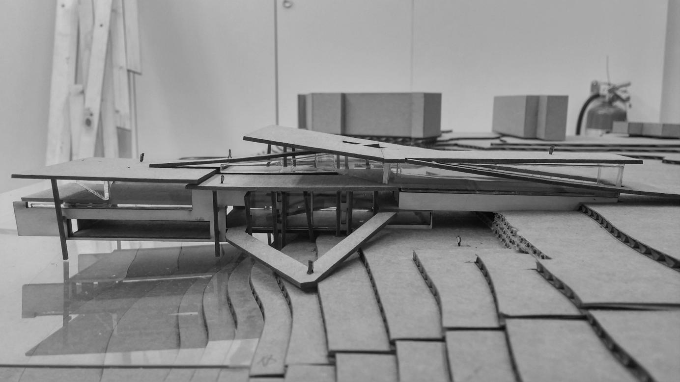 physical building model inserted into the site model
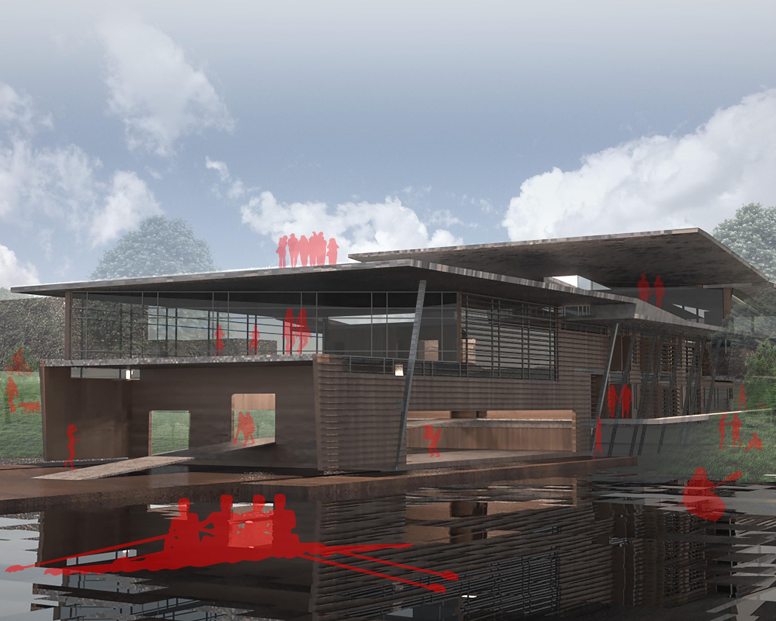
exterior view
75
west and south sides of the building, as seen from the water.
Of the sites given to us to choose from, I chose the site labeled as “Abandoned Lot” to the right. The site, located across from a hotel and at the eastern end of a bridge, had a steep grade change that interested me. Its location had prominence as a potential gateway into the city of Clemson. Also, its proximity to residences to the south and a commercially developed highway to the north provided interesting design opportunities.
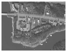
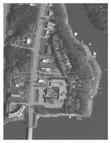
site analysis
diagrams
right: regional connectivity bottom, left to right: gateway conditions; proximity to residences; sun and wind; water levels
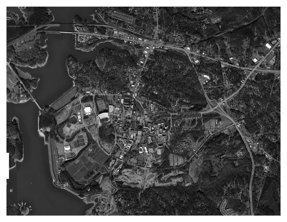
work on this page completed in collaboration with five other students.
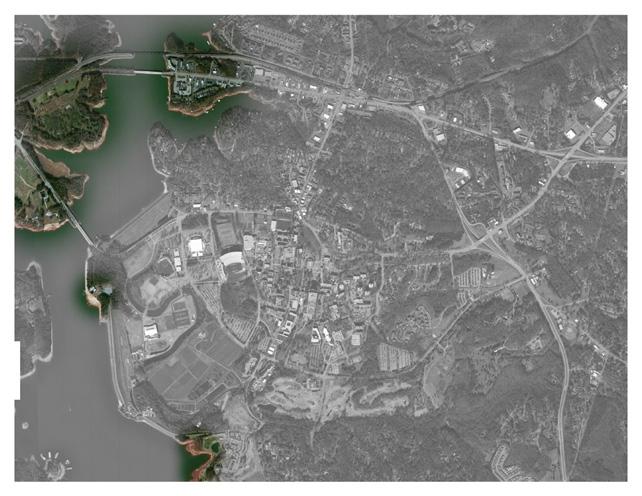
ABANDONED LOT NEWSING PROPERTY - too far; - too much land area; Y BEACH - too programmed already; EXISTING BOATHOUSE AND ROWING CENTER BEHIND MADREN CENTER - too small; - too close to golf course; - poor access; FLOOD LEVEL +16.00 feet LAKE LEVEL 0.00 feet DROUGHT LEVEL Clemson University Gateway opportunity for city of clemson gateway N 10˚ 20˚ 30˚ 40˚ 50˚ 60˚ 70˚ 80˚ deg ees bo ehorzion summ oltic inte s sunrise 6:18 am sunrise sunset 8:46 pm sunset 5:24 pm summe wind sp ngwnds wnterwind falwnd Residential properties near site 00 3000 1500 N SITE and CONTEXT Highway 123 dist: 0 mi HIGHWAY 76 DOWNTOWN CLEMSON College Avenue dist: 0.84 miles CLEMSON UNIVERSITY Sikes Hall dist: 1.08 miles EXISTING BOATHOUSE Beach Drive dist: 1.19 miles Y BEACH YMCA Circle dist: 0.97 miles MADREN CENTER Madren Center Drive dist: 1.9 miles HIGHWAY 123 HIGHWAY 93 PERIMETER ROAD GREENVILLE: 28 miles CENTRAL:4.2miles ANDERSON: 17.2 miles SENECA:6miles
site selection
massing progression
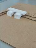
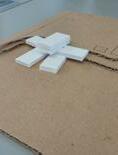
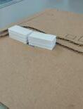
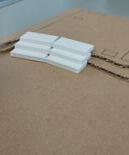
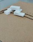
left to right: separation of private, semi-private, and public program; arrange program along topography; pierce with boat circulation; pierce with public circulation; extend landscape onto roof
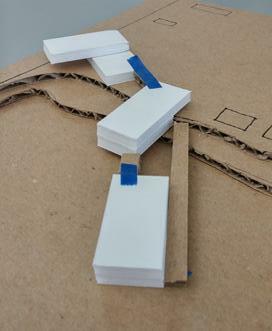
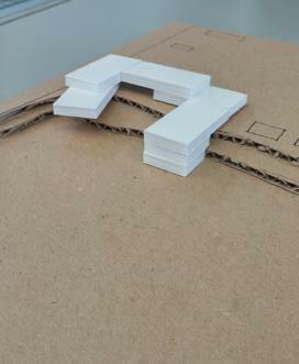
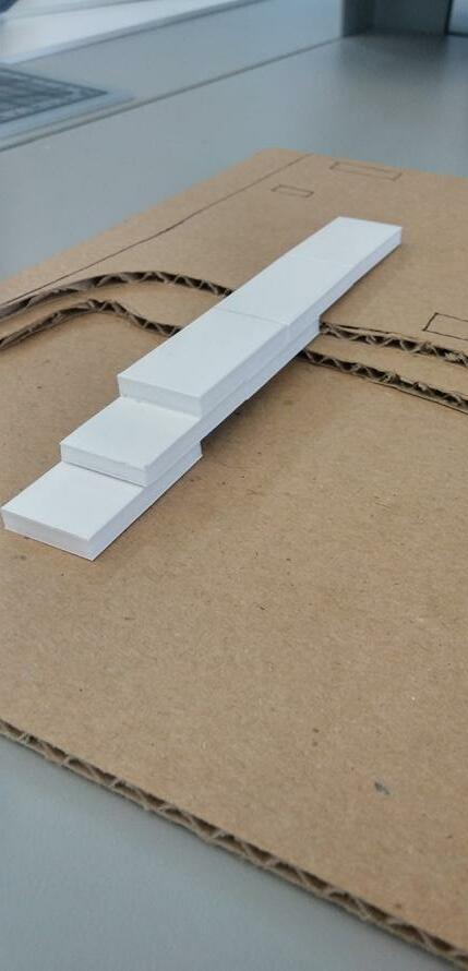
Of the above study models, the largest one interested me most because of its strong, simple gesture into the water. This is the scheme I pursued further.
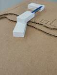
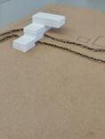
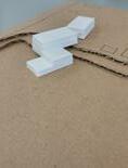
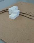
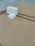
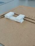
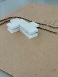
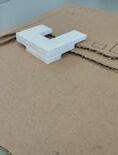
analog massing models 77
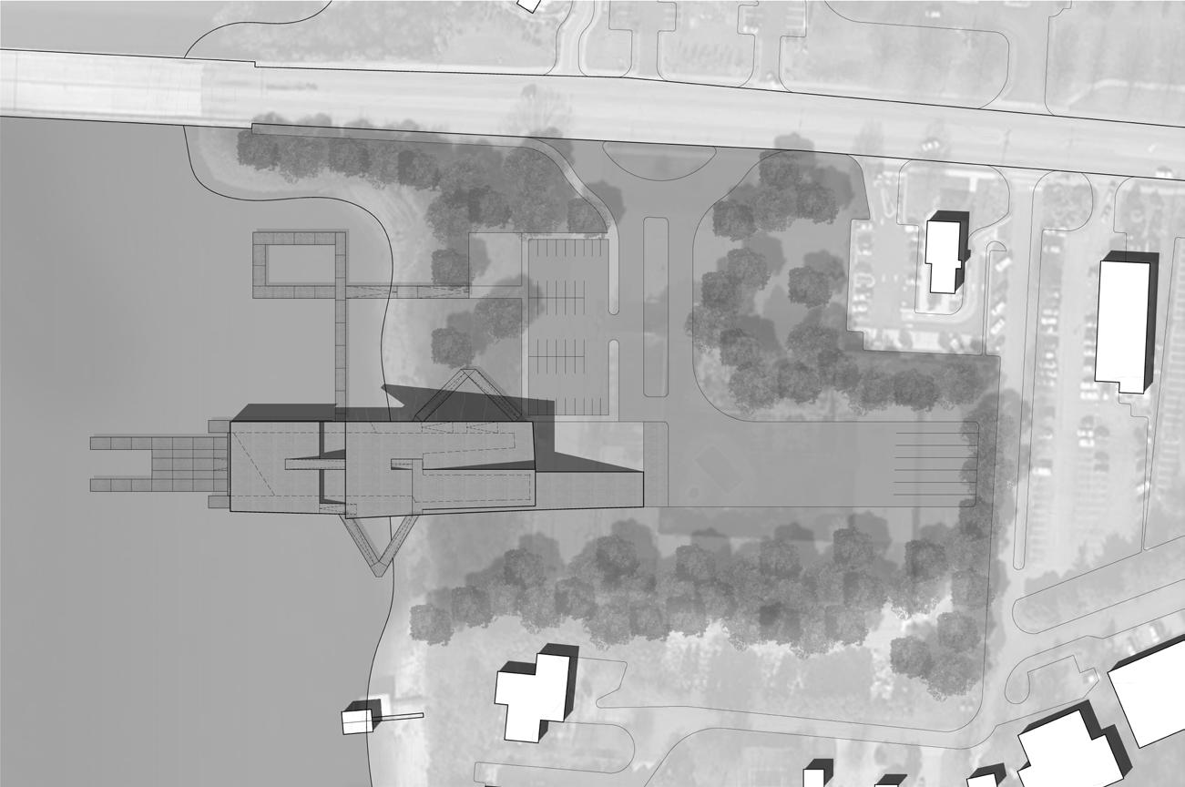
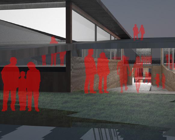
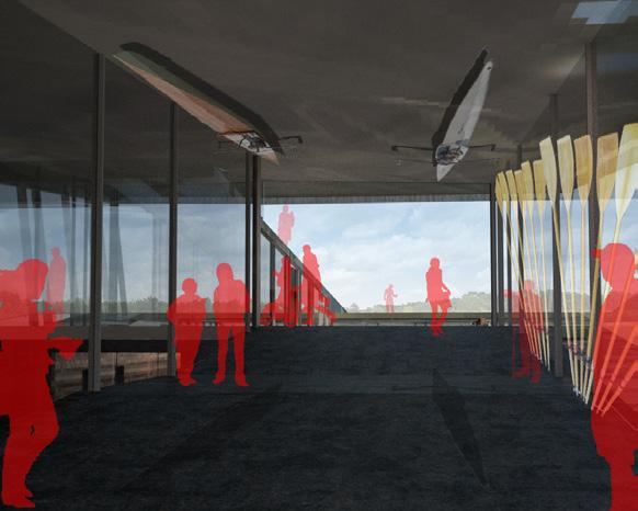
row house parking lot
public river dock highway trailer parking public green
site plan
rower green
perspectives
left to right: entry; gallery; rower lodging; boat bay
a. entry
b. gallery
c. public roof
d. reading space
e. library
f. machine storage
g. rower lodging
h. locker rooms
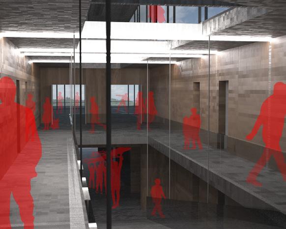
i. rower gym
j. library stacks
k. office
l. restroom
m. classroom
g. rower lodging
n. rower lounge
o. public corridor
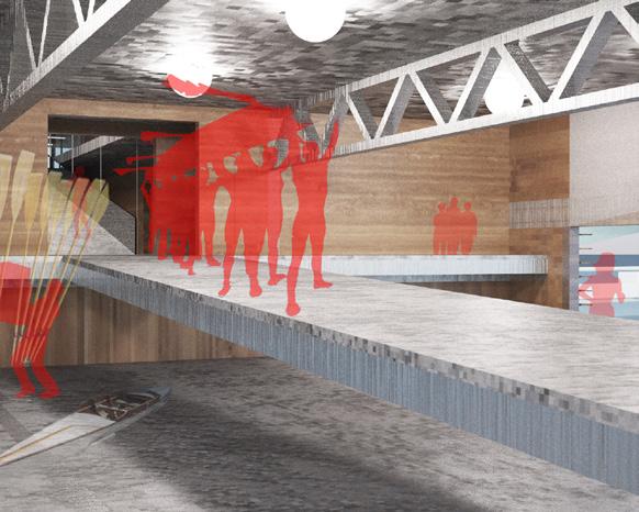
p. boat bay
q. dock
g n o p q f g h h j k l l m i a b c d e plans 79
sections
top to bottom: longitudinal section through ramp; longitudinal section through gallery; longitundinal section through library; transverse section through entry and library; transverse section through rower lodging; transverse section through boat bay
a a c c d e f b b d e f
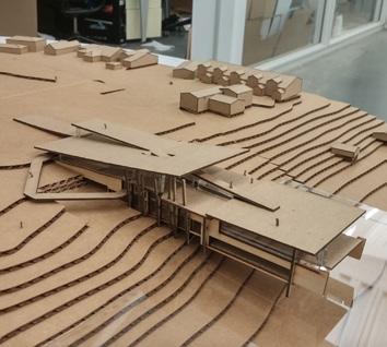
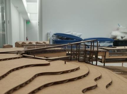
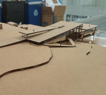
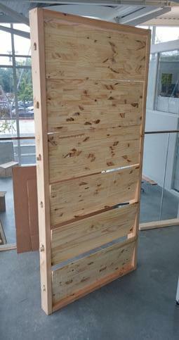
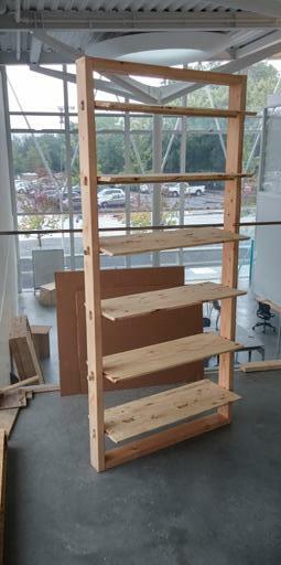
final model section detail
full-scale model of louver
81
top: open bottom: closed
UNDERGRADUATE WORK
CO-LAB
Washington, DC - Fall 2013
critic: Luis Quiros
time: 6 weeks
programs used: SketchUp and Podium, AutoCAD, Photoshop, Illustrator, & InDesign
We began the design of this collaborate maker space by designing in section. I designed this main section to have a large, full-height atrium to visually link all the programmatic elements. Public functions, such as a cafe and gallery-display space occupy the ground floor while semi-public functions, such as an auditorium and maker space, occupy the floors above. The upper floor program is divided across the atrium, separating the auditorium and childcare area from the maker and hacker spaces. These two groups of program are contained by multi-floor glass panels while figural staircases cross the atrium. Service is moved the north side.
I conceived of the parti of this building as a continuation of the public realm into a large, multi-story, light-filled atrium into which volumes of the think/make space would be inserted. The volumes of think/make spaces were divided across the atrium, with the auditorium and children’s space facing 14th street and the hacking, collaborative, and fabrication spaces facing the alley. visitors enter the building from the west and enter the lobby with views into the eating space and large performance/exhibition space. a staircase allows visitors to ascend on axis halfway, then the landing reorients visitors 180 degrees, where they finish the ascent to the auditorium. Staircases with similar forms lead to the floors above, ending with a rooftop terrace facing 14th street. Wood panels cover the walls of the atrium, appearing warm and glowing in the light. The wood directs visitors up the staircase. Smaller beige tiles of a similar scale cover the walls of the auditorium and children’s space while larger metal plates cover the walls of the hacking, collaborative, and fabrication spaces.
A series of steel trusses contained within figural concrete support the floors and roof slabs. Smaller steel beams frame into the trusses, supporting the concrete slabs and decking. Steel columns placed at twenty-foot intervals originating from the corners of the thirty-foot-by-thirty-foot atrium support the trusses. I zoned the plans of the building to place all servant spaces (fire stairs, elevators, storage, and bathrooms) against the north party wall.
The two volumes of think/make spaces are contained by multi-story height glass walls, punctured by floor slabs and circulation spaces. Think/make spaces interact across the atrium using communal lounges placed against the south party wall. The west elevation projects the zoned interior with a concrete core containing the servant spaces. The volume of the auditorium projects from a glass facade, covered in wood panels. Spaces along the west side of the building are shaded with louvers and overhangs.
84
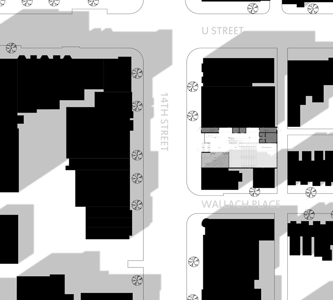
Site plan
model progression
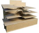
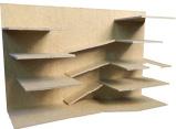
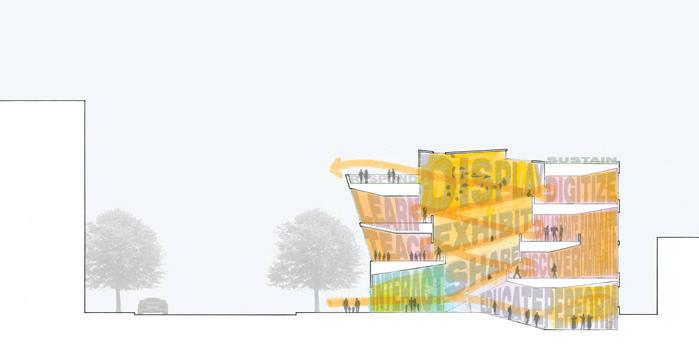
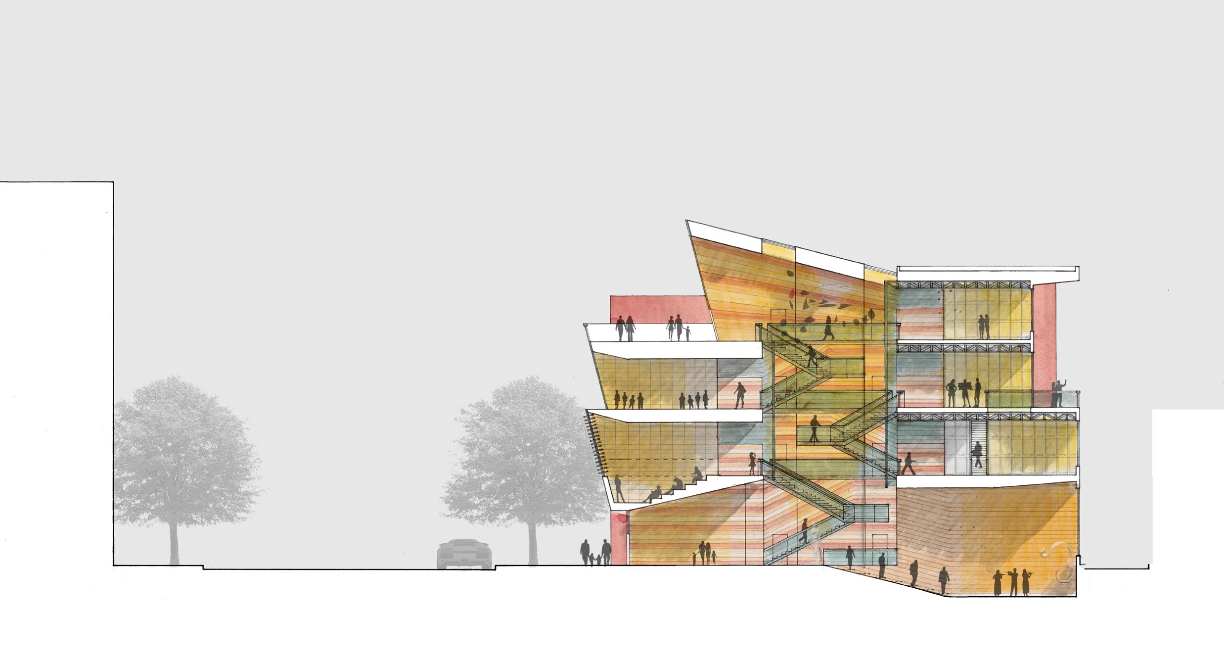
section progression
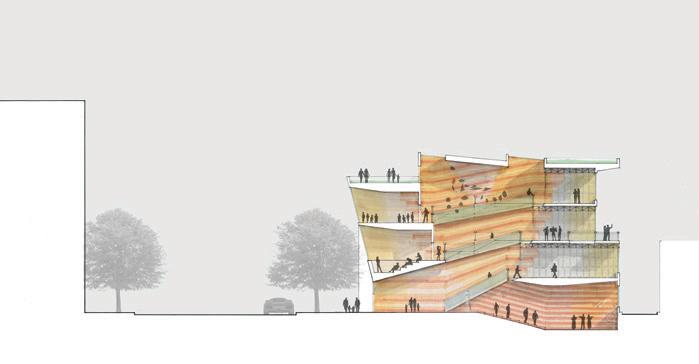
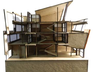
87 39
building plans
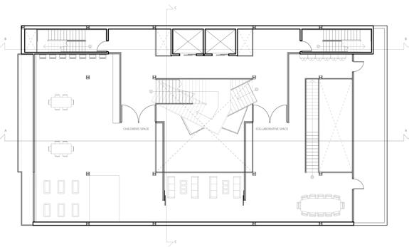
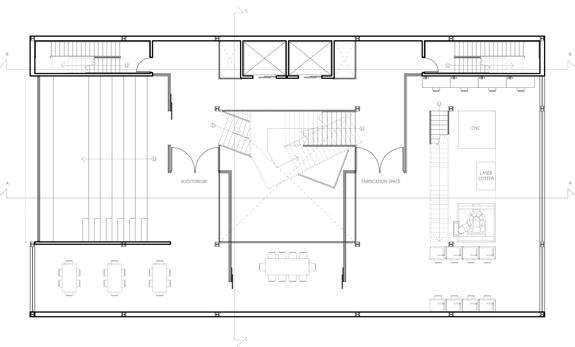
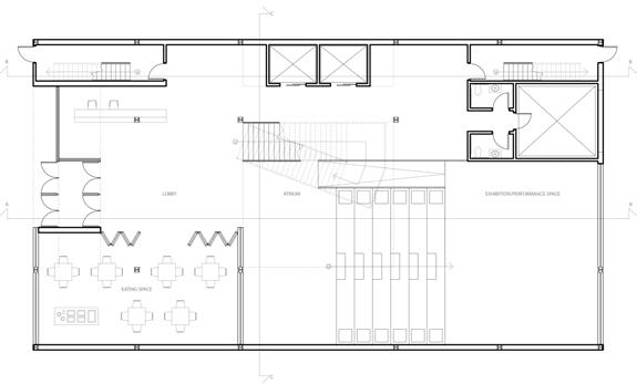
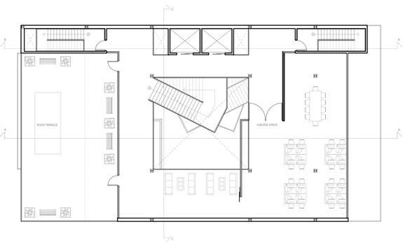
top to bottom: fourth floor plan; third floor plan; second floor plan; ground floor plan
service core
hacker space
stair atrium
roof terrace
user lounge
service core
co-lab space
stair atrium
children’s space
user lounge
service core
fabrication space
stair atrium
auditorium
user lounge
service core
lobby
stair atrium
performance space
cafe
design drawings
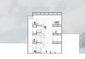
top: section perspective
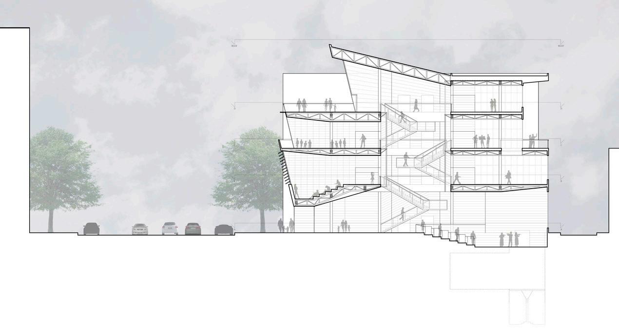
middle left: 14th Street elevation
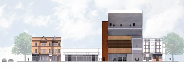
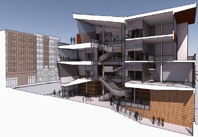
middle right: transverse section
bottom: technical longitudinal section
89 41
ENVISION SALISBURY
Salisbury, MD - Spring 2014
critic: Michael Ezban time: 12 weeks (6 weeks urban design, 6 weeks building design) programs used: SketchUp and Podium, AutoCAD, Photoshop, Illustrator, & InDesign
Similar to Salisbury, this proposed scheme functions as both a gateway and destination, a gateway to riverfront recreational activities and a destination for city cultural events. Service spaces, all contained within a 15-foot-high volume, wrap around, and nestle the larger public spaces. The steel structure exposes itself in these larger public spaces while walls surround the structure in the service spaces. All large public spaces are flexible enough to host a variety of events including performance, exhibitions, lectures, and receptions. The lobby gently caps the space between the brick-clad service volumes, allowing for views through the lobby and to the river.
90
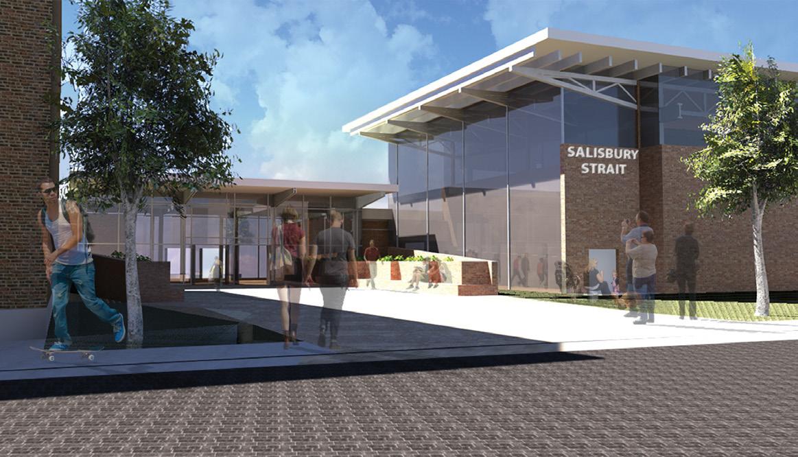 Exterior view of main entrance from Circle Avenue
community workshop
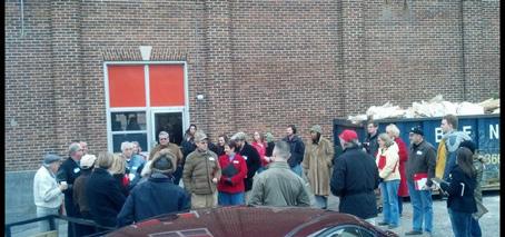
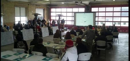
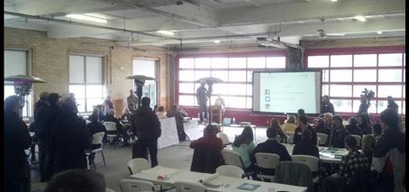
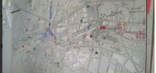
above: pamphlet made by the studio to lead community members around their own city to understand more about their needs and desires for a public building
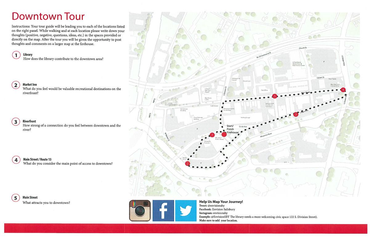 right: photos from the community workshop (I am pictured at the head of the table in the middle left photo)
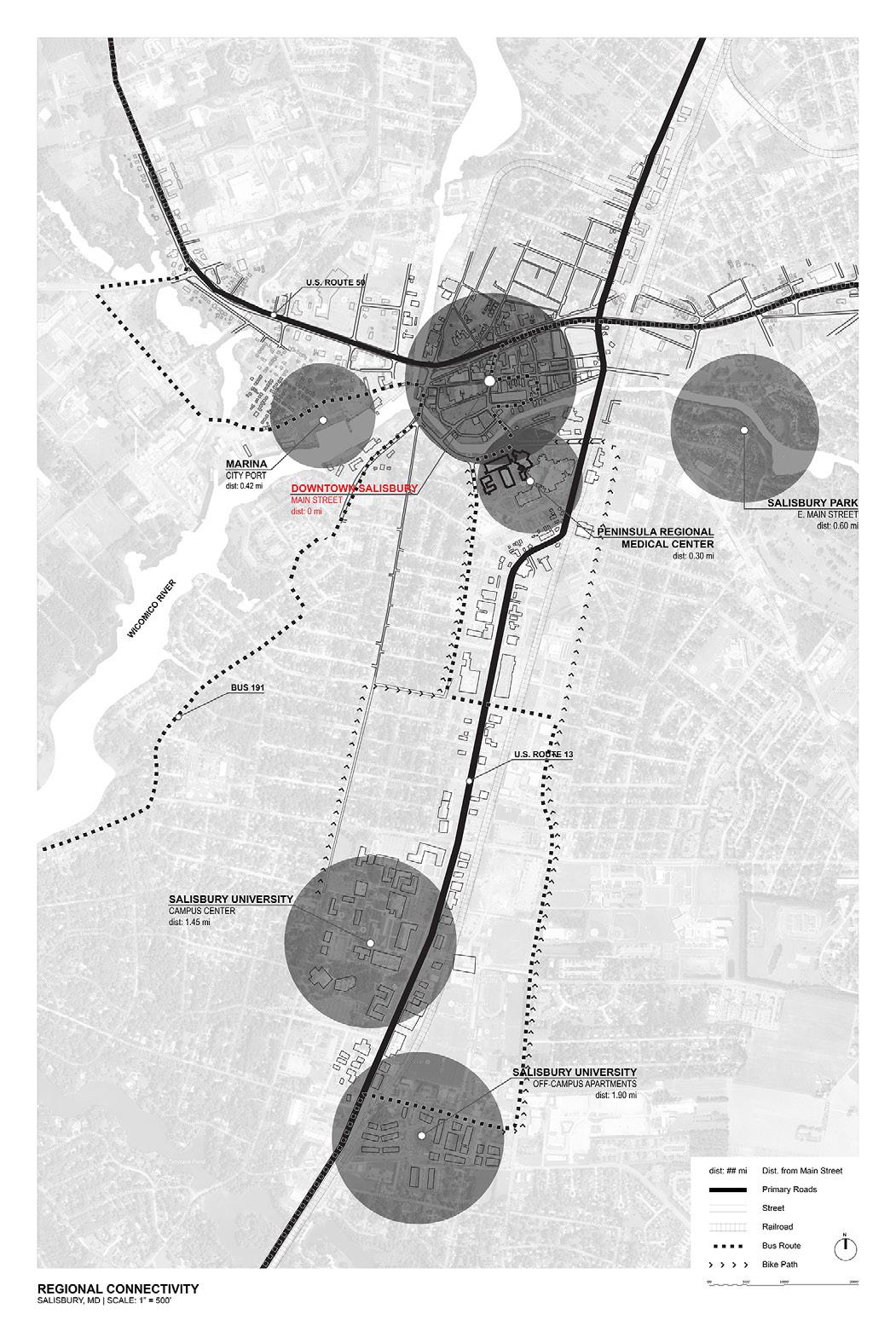
work on this page completed in collaboration
urban analysis top: regional connectivity 93 45
with Adam Louie.
urban design drawings
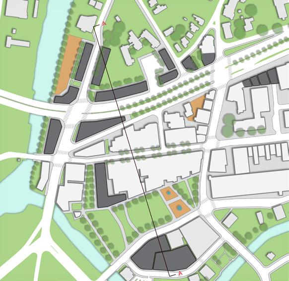
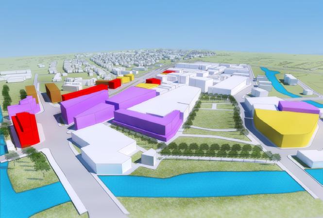
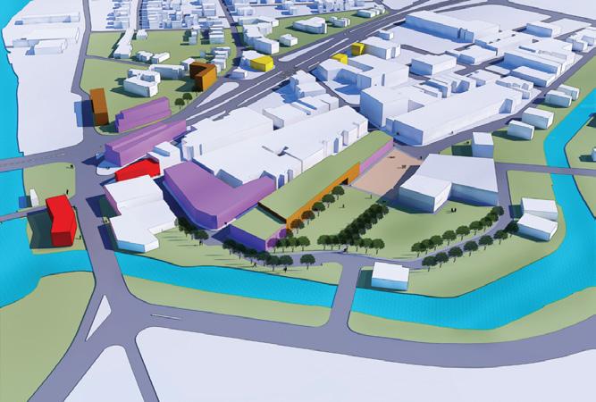
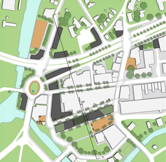
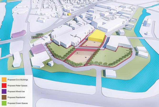
top: scheme 1 - 75% natural, 25% built; middle: scheme 2 - 50% natural, 50% built; bottom: scheme 3 - 25% natural, 75% built
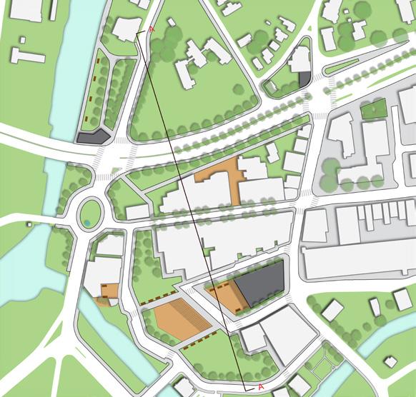
work on this page
completed in collaboration with Adam Louie.
top: site strategies
bottom: site plan
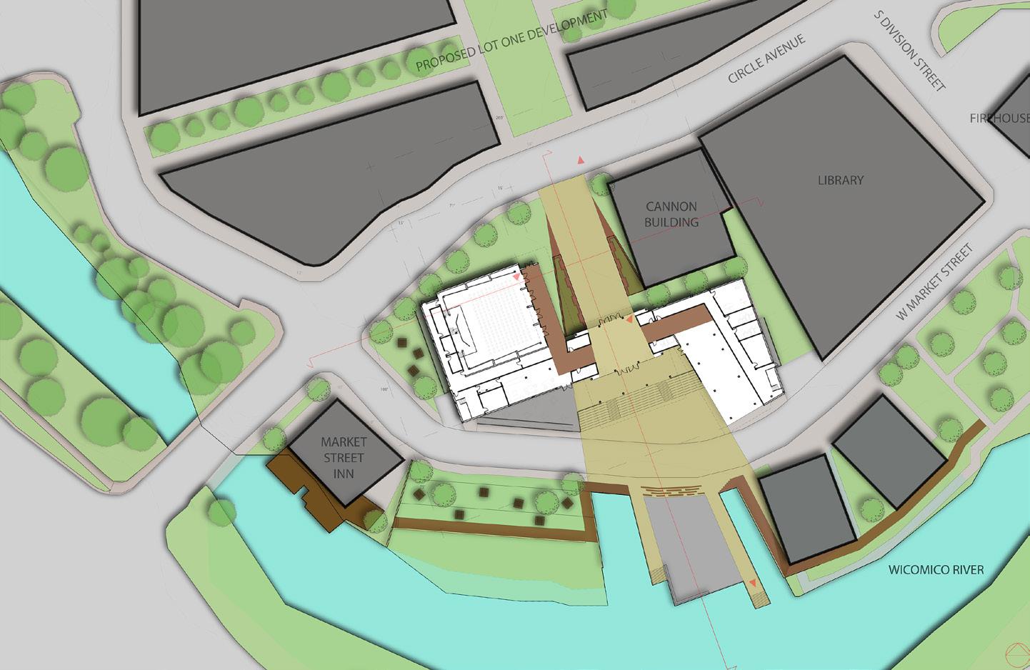
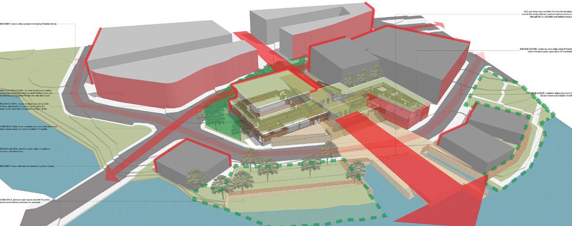
site design
95 47
design drawings
top to bottom: plan;
section through lobby;
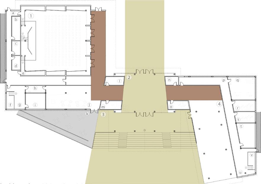
section through great space; north elevation
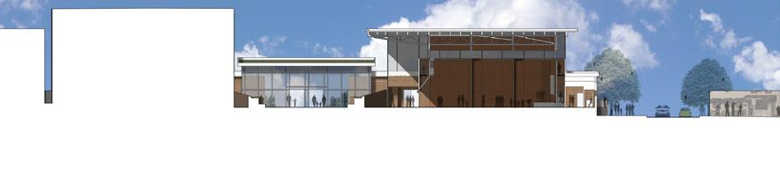

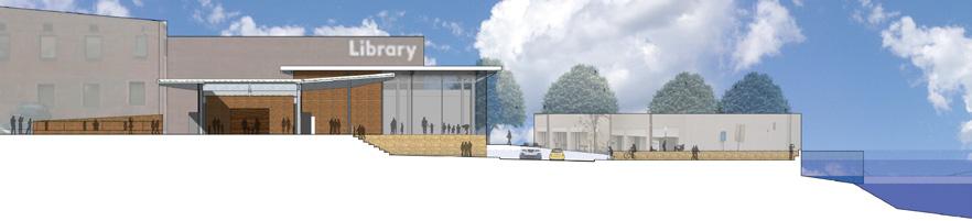
a. service corridor
b. green room
c. men’s changing room
d. women’s changing room
e. great space service space
f. loading dock
g. storage
h. kitchen
i. mechanical room
j. Strait Java cafe
k. Strait Java cafe patio
l. coat room
m. women’s restroom
n. ticket office
o. men’s restroom
p. service corridor
q. office(s)
r. women’s restroom
s. men’s restroom
t. mechanical room
u. storage
v. loading dock
1. Great Space
2. Lobby
3. Outdoor Terrace
4. Exhibition Space
design drawings
right: lobby perspective
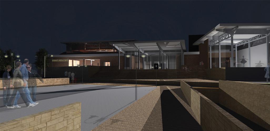
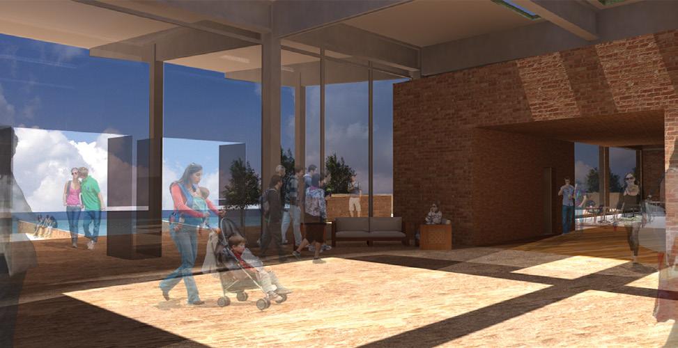
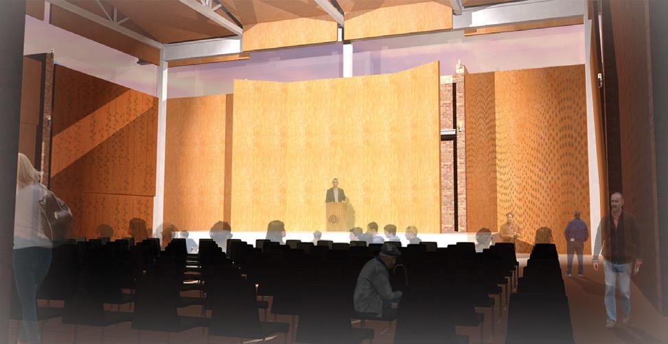
below: lobby component axonometric
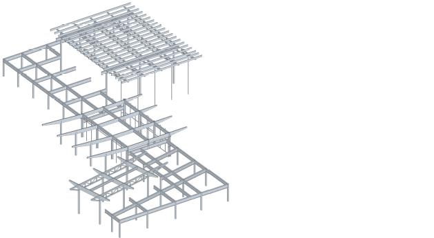
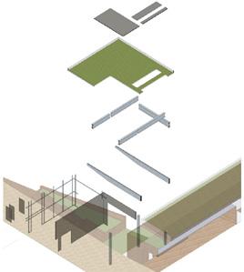
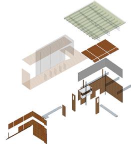
left: great space perspective
below: great space component axonometric
97 49
right: view of river elevation below: structural axonometric
PHOTOGRAPHY
SELECT PHOTOGRAPHY
While I don’t consider myself a particularly skilled photographer, I always end up with hundreds of photos from trips. Some of the photos are meant to be nice and composed “hero shots” while others are quick close-ups for personal, future reference. Occasionally, I take a photograph that I find surprisingly compelling and it sticks in my mind. I love wandering around and capturing images of buildings and elements that make me pause or capture my attention. The following photographs, taken on various trips to major cities around the world during trips spanning from high school to post-graduation, represent a selection of photographs I find particularly striking. They show my wide range of interests including public spaces, museums, adaptive reuse, material juxtapositions, framing elements, aerials, color, and details.
While some photographs show larger gallery spaces, such as those of the Musée d’Orsay or the Rijksmuseum, others show specific moments I found interesting, such as the cornice of Sant’Ignazio, the axial organization of both St. Peter’s Square and the Plaza de España, the juxtaposition of material in the Caixa Forum, the blending of materials in the Neues Museum, the oculus in the Broad Museum, or the arrival sequence in the Kyushu Geibunkan .
100
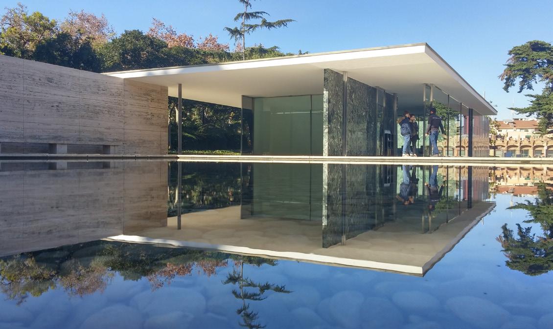 Barcelona Pavilion, Barcelona
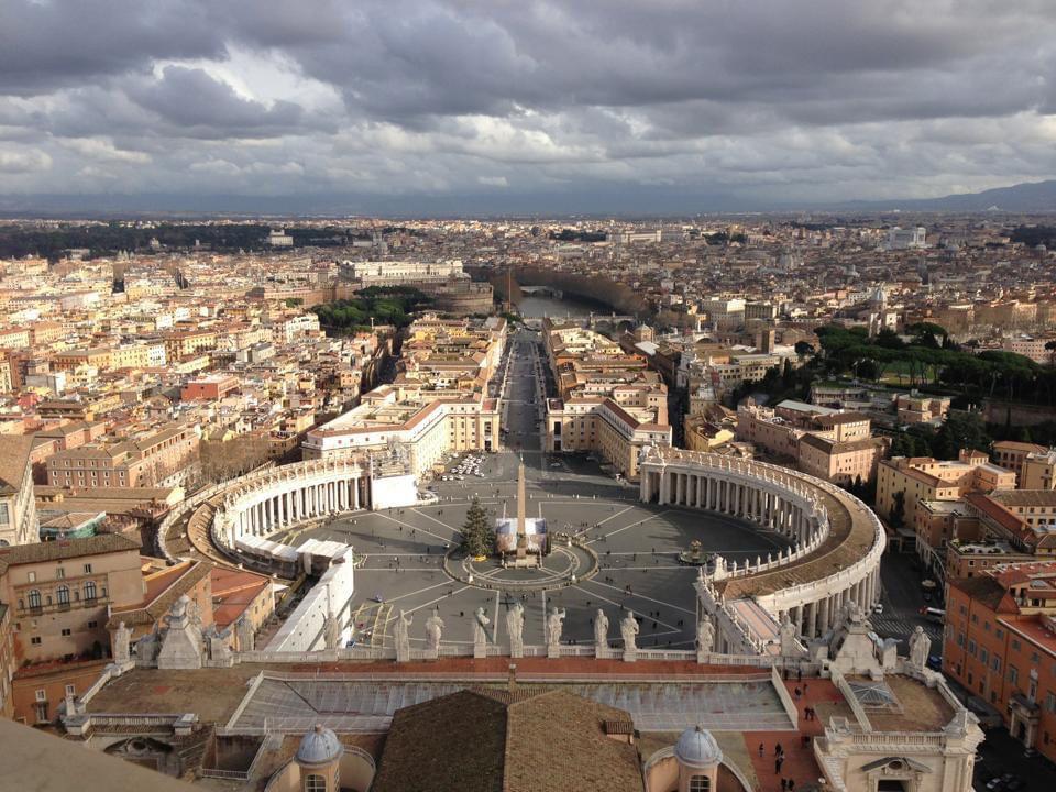
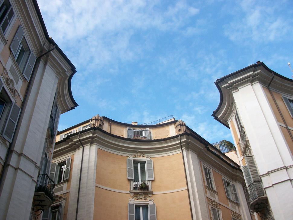
Piazza Sant’Ignazio, Rome, 2013
view of St. Peter’s Square from St. Peter’s Basilica, Vatican City, 2013
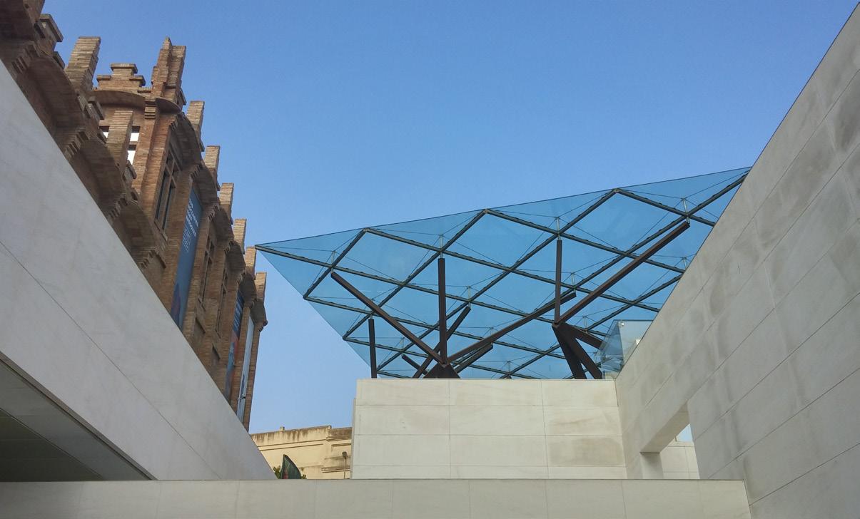
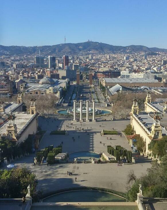
CaixaForum,
103
Barcelona, 2016 view of Plaza de España from the MNAC, Barcelona, 2016
LACMA, Los Angeles, 2016
Parc de la Villette, Paris, 2017
Delta Works, Maeslantkering, 2016 Rijksmuseum, Amsterdam, 2016 Neues Museum, Berlin, 2016 KTH, Stockholm, 2016 105
Burj Khalifa, Dubai, 2016
Hagia Sophia, Istanbul, 2016
Broad Museum, Los Angeles, 2016
Fukuoka Tower, Fukuoka, 2017 Kyushu
Fővám tér station, Budapest, 2017 107
Geibunkan, Fukuoka, 2017
2323 40th Place NW, Apt. 205 Washington DC, 20007 301.832.0315 thomas.masino.arch@gmail.com issuu.com/tommymasino
