2 ELECTRIC SHEARMU16 USE ANDINSTRUCTIONSMAINTENANCE MANUAL

MU16 230V 2 ELECTRIC SHEAR AVAILABLE IN THE FOLLOWING VERSIONS: SINGLE-PHASE ELECTRIC MOTOR 230 V 50 Hz FIXED HEADS AVAILABLE NAME OF MACHINE P/N CUTTING HEAD MU16 1.50.1838 INDEX

MU16 230V 3 0 DESCRIPTION OF THE MACHINE 5 0.01 MACHINE COMPONENTS......................................................................................................5 0.02 SAFETY AND DANGER STICKERS CE PLATE.....................................................................6 0.03 LIST OF ACCESSORIES INCLUDED IN THE SUPPLY ...........................................................7 1 TECHNICAL FEATURES...........................................................................................................7 1.01 HYDRAULIC, MECHANICAL AND ELECTRICAL SPECIFICATIONS ......................................7 2 DELIVERY, COMMISSIONING AND SET-UP .......................................................................8 2.01 DELIVERY 8 2.02 ELECTRIC MOTOR.................................................................................................................8 2.02.01 ELECTRICAL CONNECTIONS ......................................................................................8 2.02.02 COMMISSIONING 9 2.03 MANUAL RETURN LEVER......................................................................................................9 2.04 EQUIPMENT OPERATION....................................................................................................10 2.04.01 STARTING 10 2.04.02 CUTTING.....................................................................................................................10 2.05 FORESEEN USE AND RESIDUAL RISKS.............................................................................10 2.05.01 SAFETY DEVICES.......................................................................................................11 3 ROUTINE MAINTENANCE.....................................................................................................12 3.01 CHANGING AND TOPPING UP THE OIL ..............................................................................12 3.02 CHECKING SCREWS 14 3.03 CHECKING BLADES.............................................................................................................14 3.04 HYDRAULIC COMPONENTS................................................................................................15 3.04.01 CLEANING THE PISTON 15 3.04.02 ADJUSTING THE STROKE OF THE UPPER BLADE 15 3.04.03 MANUAL RETURN VALVE DOES NOT CLOSE 16 3.04.04 MAX. PRESSURE VALVE INCORRECTLY ADJUSTED 16 3.05 ELECTRIC MOTOR...............................................................................................................16 4 POTENTIAL PROBLEMS AND MEASURES TO BE ADOPTED ..................................................16 4.01 GENERAL .............................................................................................................................16 4.02 TROUBLESHOOTING THE MOTOR.....................................................................................17 4.03 TROUBLESHOOTING THE HYDRAULIC COMPONENTS....................................................17 5 STORAGE AND RESTARTING ..............................................................................................18 5.01 STORAGE.............................................................................................................................18 5.01.01 ELECTRIC MOTOR 18 5.01.02 CYLINDER AND HYDRAULIC COMPONENTS 19 5.02 RESTARTING .......................................................................................................................19 6 MACHINE DISPOSAL..............................................................................................................19 A brief legend indicating the most important symbols used in this manual is shown below.
THIS SYMBOL WARNS USERS TO PAY SPECIAL ATTENTION WHEN FOLLOWING THE RELATIVE INSTRUCTIONS. FAILURE TO OBSERVE THESE INSTRUCTIONS CAN CAUSE THE MACHINE TO OPERATE INCORRECTLY.
MU16 230V 4
“OPERATOR”: A person suitably trained and authorised to operate, adjust, clean and transport the machine.
“MACHINE BODY”: The equipment described in this manual.
“ELECTRIC TOOL”: Used in the safety precautions, it is a more general definition of the machine in question as it refers to mains-powered electric tools (with cable) or batterypowered electric tools (cordless).
“MAINTENANCE MAN”: A person trained and authorised to perform routine maintenance on the machine and replace certain components.
THIS SYMBOL INDICATES POSSIBLE HAZARDS, TAKE ALL PRECAUTIONS TO PREVENT THESE SITUATIONS FROM OCCURRING. BEFORE WORKING ON THE MACHINE, CAREFULLY READ ALL THE INSTRUCTIONS, ESPECIALLY THOSE CONTAINED IN BOXES.

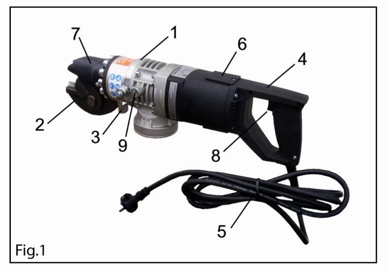
MU16 230V 5 0 DESCRIPTION OF THE MACHINE CAUTION!! FIRST READ THE MANUAL REGARDING THE GENERAL AND SAFETY REGULATIONS! 0.01 MACHINE COMPONENTS This machine is fitted with a single-phase alternating current motor. The equipment comprises: a motor, a hydraulic pump driven by the motor, a rod actuator (piston) driven by the oil pressured by the pump, a fixed head with tool. Fig. 1 shows the main parts of the machine fitted with a motor, in particular: 1. cylinder with hydraulic components 2. head with tool 3. release lever or double acting lever 4. grip with on/off switch 5. electrical connecting cable complete with plug 6. electric motor 7. safety mask 8. start button 9. oil cap
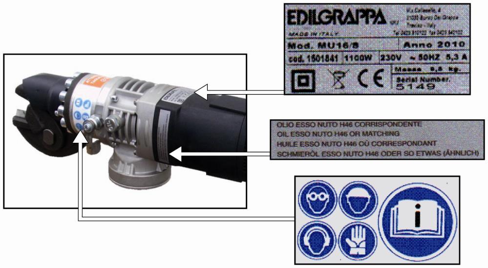
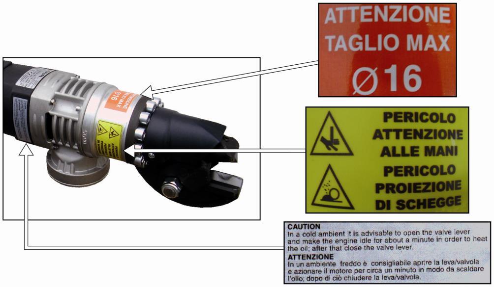
MU16 230V 6 0.02 SAFETY AND DANGER STICKERS - CE PLATE Position of plate and safety and danger stickers on the machine: Observe the warnings on the plates and stickers. Failure to do so could lead to injury or death. Make sure the plates and stickers are attached and legible. If not, apply them or request the maker for replacements. ATTENTIONMAX.CUT Ø 16 BEWAREDANGEROFHANDSDANGERFLYINGSPLINTERS
MU16 230V 7 0.03 LIST OF ACCESSORIES INCLUDED IN THE SUPPLY Case General safety rules, Use and maintenance instructions Declaration of conformity Warranty certificate Emergency key 1 TECHNICAL FEATURES 1.01 HYDRAULIC, MECHANICAL AND ELECTRICAL SPECIFICATIONS Maximum cutting size and characteristics of material [ mm and daN/mm2 ] 16 mm / 65 daN/mm² Maximum output force from rod [ t ] 14 8 Maximum operating pressure [ bar ] 560 Dimensions: Length X Width X Height [ mm ] MU16 520 x 125 x 147 Closing and opening time [ s ] 2/2 Weight [ kg ] 9.5 Guaranteed no load LwA sound level (CEI EN 60745 1 and CEI EN 60745 2 8) [ dB ] 98 No load operator Lpa (CEI EN 60745 1 and CEI EN 60745 2 8) [ dB ] 87 Vibrations when cutting diam. 16 mm rod (CEI EN 60745 1 and EN ISO 5349) MU16 9.78 m/s² Input voltage [ V ] 230 Frequency [ Hz ] 50 Electrical power [ W ] 1100 Input current [A] 5 3 Insulation class II RPM 10000
2.01 DELIVERY
In the event of damage, send a written complaint to the forwarder within 8 days of Promptlyreceipt.
2.02 ELECTRIC MOTOR 2.02.01 ELECTRICAL CONNECTIONS THE USER SYSTEM AND THE RESPECTIVE CONNECTIONS MUST BE MADE IN STRICT OBSERVANCE OF THE REGULATIONS IN FORCE, BY COMPETENT PERSONNEL QUALIFIED TO DO THE JOB. BEFORE CONNECTING THE APPLIANCE USING THE PLUG SOCKETS, TURN THE MAIN SWITCH TO ITS OPEN POSITION "O".
The machine is normally shipped and delivered inside a special hard case, well secured and in a stable position (see adjacent figure). All the ordered material is inspected before delivery to the customer. Upon receipt, check the machine for any damage (breakages or major denting) caused during transport. If so, immediately inform the shipping company and write the “Accepted subject to checking” clause on the Delivery note.
Also check the delivered materials against the detailed shipping list.
The machine can be moved easily both when it is inside its special rigid case, using the upper handle, and by gripping its upper or lower handle. Loads must be moved in compliance with current occupational safety regulations. After use, put the machine back into its case or place it on a stable surface, making sure this can withstand its weight.
MU16 230V 8 2 DELIVERY, COMMISSIONING AND SET-UP
inform Edilgrappa s.r.l. if major damage, caused during transport, is found upon receipt, or if any parts are missing.

MU16 230V 9 2.02.02 COMMISSIONING These machines do not need any adjustment or particular precautions before Thecommissioning.onlycontrolsto perform concern: Machine integrity: make sure that nothing happened during transport that could damage the insulation or mechanical checkCompletenessparts.ofsupply:thatallthesupplied accessories are fitted. - Oil checklevel:the oil level and top up if necessary as per the instructions in Para 3.01. IMPORTANT: Before loosening the oil cap carefully read the instructions in Para 3.01. 2.03 MANUAL RETURN LEVER
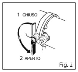
1 CLOSED2OPEN
The manual return lever has two positions (see fig. 2)
Position 1: valve closed. The piston work and return stroke takes place automatically. Position 2: valve open. To interrupt the work stroke or in case of emergency move the lever to position 2 to return the piston to its home position.
IMPORTANT: If the machine does not work make sure the manual return lever is in position 1.
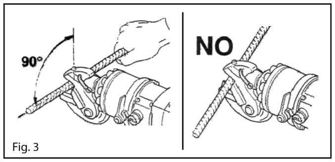
2.04.02 CUTTING Position the blade perpendicular to the axis of the work piece (fig. 3).
If the cutting thickness is greater than the limit established for the tool its blades may Afterbreak.correctly positioning the blade on the workpiece, press the start button and hold it down until cutting has been completed.
2.04.01
2.05 FORESEEN USE AND RESIDUAL RISKS
MU16 230V 10 2.04 EQUIPMENT OPERATION
STARTING Insert the plug in a suitable power socket and follow the instructions below, depending on the kind of machine involved.
The machine must only be used to cut items in metal, such as electrowelded mesh, round bars, chains, padlocks, etc…in the building trade, industry and for emergency/rescue purposes. Maximum cutting diameter is 16 mm and the unit tensile strength of the material (steel) must not be greater than 640 N/mm². Do not use the machine to cut sheet steel or other items not mentioned above.
The machine may only be used if powered by an electrical system compliant with legislation and current law (suitably connected to an earth system and protected from current surges and short circuits). Any use other than that expressly indicated shall be considered as improper and therefore not permitted. Edilgrappa S.r.l. declines all liability for any improper use of the machine and for any modification or change made to it.
IMPORTANT: Position the blade so as to minimise the cutting thickness. Non perpendicular blade positions with respect to the workpiece increase cutting thickness.
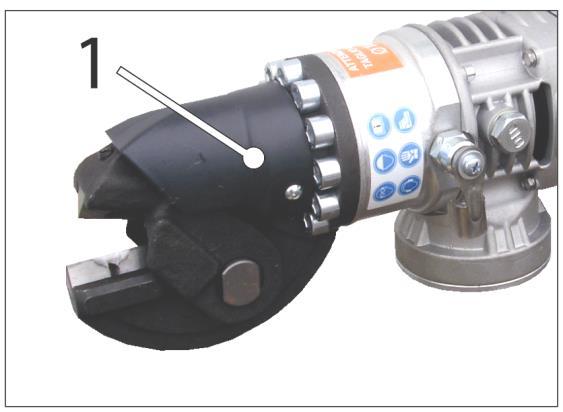
The machine is fitted with a safety device preventing contact with the upper part of the tool as it returns after cutting. It is a plastic guard secured to the machine with 2 screws (part. 1 in fig. below). Never tamper with the safety devices
2.05.01 SAFETY DEVICES
Cutting
MU16 230V 11
Operators must observe the instructions in this manual in order to minimise the risk of accidents. In particular, they must pay attention when working in conditions that could cause:Possible burns from overheated metal parts; Injury due to incorrect positioning or inadequate lifting or moving Injury caused by splinters discharged from the work piece.
People remaining in the vicinities of the machine while it is working are subject to the following risks: flying debris (dangerous objects, etc…); Operating temperature -40° ÷ +50° C and max. unit tensile stress 16 mm STEEL R=640 N/mm² It is strictly forbidden to cut sheet metal. It is strictly forbidden to use the machine for purposes other than those indicated in this installation and maintenance manual. It is forbidden to use the machine in areas subject to the risk of explosion.
MU16 230V 12 3 ROUTINE MAINTENANCE 1.All maintenance, inspection and cleaning operations must be performed with the power supply disconnected and the machine cool (see the person responsible in the maintenance schedule); 2.Maintenance operations must be performed in a suitable place according to current safety regulations; 3.Before any maintenance intervention, thoroughly clean the machine (see Paragraph 5.01); 4.Wear suitable personal protective equipment while performing maintenance AFTERwork.MAINTENANCE WORK, MAKE SURE THE GUARDS ARE PUT BACK INTO THEIR CORRECT PLACE.Periodic maintenance schedule Frequency Operation Method Person EVERY 8 HOURS CHECK THE INTEGRITY OF THE MACHINE Visual Operator / CLEAN THE PISTON Para 3.04.01 Operator EVERYHOURS1600 CHANGE THE OIL Para 3.01 Maintenanceman EVERY 8 HOURS CHECK THE TIGHTNESS OF NUTS AND BOLTS Para 3.02 Operator EVERY 8 HOURS CHECK THE BLADES FOR WEAR Para 3.03 Operator / REPLACING BLADES Maintenanceman If you have any doubts about ordering spare parts or performing complex maintenance work, contact your authorised dealer. 3.01 CHANGING AND TOPPING UP THE OIL When changing or topping up the oil, make sure no impurities contaminate the oil or enter the tank. Impurities in the oil can irreparably damage the hydraulic components. ALWAYS MAKE SURE THE OIL CONTAINS NO IMPURITIES DO NOT USE DIRTY TOOLS DO NOT WORK IN DUSTY AREAS CHANGING THE OIL: USING A SUITABLE DISPENSER, PREPARE THE CORRECT QUANTITY OF OIL (0.6 l) TO POUR INTO THE TANK. LEAKING OIL CAN CAUSE SHORT CIRCUITS, FIRE AND EXPLOSIONS.
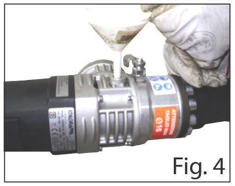
4. Slowly pour in the correct quantity of oil (0.6 l) using suitable equipment (e.g. a funnel as shown in fig. 4). Only use new or clean recommended oil (as indicated on the next page);
2. Unscrew the magnetic cap (see part. 9 para 0.01) and remove any residues with the piston in its retracted position;
2. Unscrew the magnetic cap (see part. 9 para 0.01) and remove any residues;
1. Place the machine horizontally in a stable position on a work surface with the filling hole facing upwards. Place a basin under the machine to catch any oil leaks;
5. Put the oil cap on and tighten.
MU16 230V 13
1. Place the machine horizontally in a stable position on a work surface with the magnetic cap facing upwards. Place a basin under the machine to catch any oil leaks;
TOPPING UP THE OIL: Before unscrewing the magnetic cap to check the oil level, make sure the piston is fully extended and, if necessary, pull it out. If this is not done the oil may leak, air bubbles may form and/or the oil level may be incorrectly measured, thus causing the machine to operate incorrectly.
3. Totally drain the oil tank using a suitable extraction system (used oil extraction pump) so that no oil can leak into the machine;
7. Perform some piston strokes to vent the large air bubbles;
5. Fill up to the upper rim of the hole;
3. Check the amount of missing oil;
Only after completing the above operations, proceed as shown below:
6. Put back the oil cap and tighten slightly;
4. Slowly top up to the upper rim of the hole with recommended new and clean oil using suitable equipment (e.g.: a funnel as indicated in fig. 4);
8. Move the piston to its maximum extension and rapidly start and stop the motor several times (before the piston automatically retracts); 9. Complete filling; 10.Put the oil cap on and tighten.
MU16 230V 14
3.02 CHECKING SCREWS
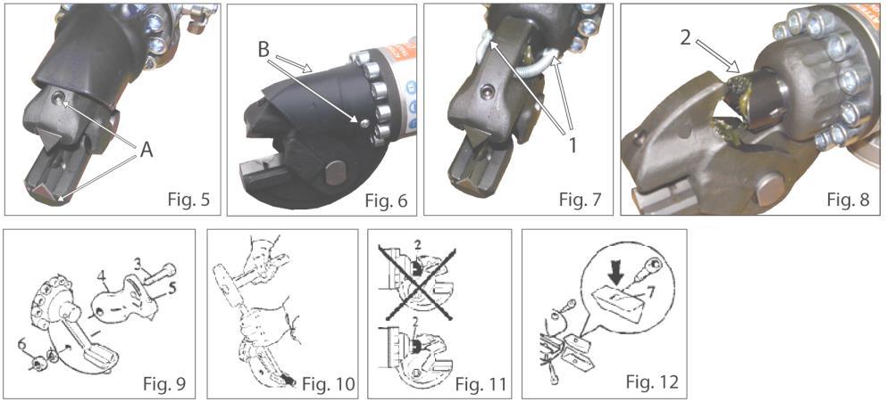
REPLACE AS SOON AS YOU NOTICE THEY ARE WORN REPLACING BLADES: Place the machine horizontally on a stable work surface and manually remove the blades after loosening the two lock screws (A) indicated in fig. 5. If the blades cannot be removed manually, proceed as follows:
When demolishing the machine or parts of it (oil, plastic, etc.) observe the regulations in force in the country in which this operation is performed.
The use of worn blades decreases the potential of the machine and can needlessly overheat the motor.
Periodically, or every day in the event of frequent or prolonged work, make sure that all the screws are perfectly tight.
8. Assembly by inserting the blades as indicated in fig. 12: the short blade in the seat of the upper mobile head with the short screw, the long blade in the seat of the lower fixed head with the long screw; Attention: position the notch (7) as indicated in fig. 12, mount the blade with the help of a copper or aluminum hammer.
7. If the blades are still in good condition, turn them 120° or mount new blades. Before mounting the blades clean them and the guides;
4.
5. Remove the upper part of the head (4) in fig. 9;
Maximum quantity: 0.6 l. Type of hydraulic oil: ESSO NUTO H46 or homologated equivalents HLP46 according to DIN 51 524 MIL H 17672 C
10.Secure the nut with washer (6) so that the upper head can move freely up and down and vice versa; 11.Secure the two screws on the piston (1) with a screw safety system (thread locker);
3.03 CHECKING BLADES
3. Remove the head drive cam (2) in fig. 8; Remove the nut and washer (6) and pull out the pin (3) in fig. 9;
6. Remove the blade with the help of a pin, as shown in fig. 10;
9. When assembling, make sure the head drive cam (2) is inserted in the right position (see fig. 11);
FAILURE TO TIGHTEN LOCK SCREWS CAN CAUSE SERIOUS DAMAGE.
1. Loosen the two lock screws (B) in fig. 6 and remove the protective sleeve;
12.Put back the guard.
2. Loosen the lateral screws (1) in fig. 7 securing the spring of the upper head;

3.04.02 ADJUSTING THE STROKE OF THE UPPER BLADE (refer to the figures in Para 3.03) To increase the stroke of the upper blade, move the adjustment screw located under the head drive cam (pos.2 fig.8) as indicated below: - move the piston fully back to its home position place the machine horizontally on a stable work surface - loosen the two lock screws (B) in fig. 6 and remove the protective sleeve remove the two lateral screws securing the spring of the upper head to access the cam (fig.7)
MU16 230V 15
3.04 HYDRAULIC COMPONENTS
3.04.01 CLEANING THE PISTON KEEP THE PISTON BODY CLEAN IN ORDER TO ENSURE THE PISTON FULLY RETURNS AT END OF ITS STROKE AS OTHERWISE A NEW STROKE WOULD NOT BE POSSIBLE
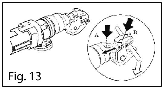
In case of operating faults caused by dirt building up on the piston head, proceed as follows (fig. 13): place the machine horizontally on a stable work surface remove the guard by loosening the two screws to the sides return the piston B to its home position using a lever clean the piston head A
ALL OPERATIONS MUST BE PERFORMED BY QUALIFIED PEOPLE IN OBSERVANCE OF SAFETY REGULATIONS.
move the head forwards and remove the cam (fig.8) using a screwdriver, turn the adjustment screw anti clockwise to increase the stroke, making sure that the piston does not turn on itself make very small adjustments to prevent the blades from overlapping and jamming mount the cam and secure the screws with the spring taking care not to overtighten them put back the guard. When assembling, make sure the cam is mounted in the correct position as shown in figure 11.
3.04.04 MAX. PRESSURE VALVE INCORRECTLY ADJUSTED In case of a pressure drop for a reason that cannot be directly identified, have a maintenance man or the maker check the maximum pressure valve is clean and calibrated.
3.05 ELECTRIC MOTOR Keep the motor surfaces clean, especially the fins on the head Keep the motor cooling slits clean and unobstructed Check the brushes for wear: replace them with authentic spare parts when their length is less than 5mm.
Remedies marked with the letter “R” require the assistance of the Authorised dealer. The remedies marked by the letter "M" require the intervention of the Manufacturer. Remedies marked with the letter “O” can be performed by the Operator.
WORK ON THE MACHINE DURING THE WARRANTY PERIOD MUST BE PERFORMED AT THE MAKER'S FACILITY
4.01 GENERAL Faults can be divided into three sections: 1. faults on the motor 2. faults on the head 3. faults not closely connected with the machine
3.04.03 MANUAL RETURN VALVE DOES NOT CLOSE If the piston is unable to perform another stroke make sure the manual return lever is closed.
MU16 230V 16
4 POTENTIAL PROBLEMS AND MEASURES TO BE ADOPTED
MU16 230V 17 4.02 TROUBLESHOOTING THE MOTOR FAULT POSSIBLE REASON POSSIBLE REMEDY PERFORMED BY MOTOR DOES NOT START Broken power cable Replace cable with one having the same specifications M Faulty plug Replace M Stator windings Replace R Rotor windings Replace R Switch Replace R No electric power Check the line and the cable protections M ELECTRICOVERHEATEDMOTOR Worn brushes Replace R Worn manifold Replace or overhaul R Insufficient power supply Check the line, the protections of the electric panel and the tightness of the connection terminals M Partial fault of the stator windings Replace R Partial fault of the rotor windings Replace R Windings dirty Clean M Ventilation slits obstructed Clean O Fan broken Replace R Motor supports worn Replace R Mechanical faults on the head Overhaul R ELECTROMAGNETICDISTURBANCESINLINE Fault in disturbanceanti filter Replace R Manifold worn Replace R Brushes worn Replace R 4.03 TROUBLESHOOTING THE HYDRAULIC COMPONENTS FAULT POSSIBLE REASON POSSIBLE REMEDY PERFORMEDBY STROKEOUTWARDDOESNOTBEGIN Return stroke incomplete Push back the piston O Return spring broken Replace O Max. pressure valve dirty Consult the Maker / Manual return valve dirty Clean O Manual return valve faulty Repair M Oil tank empty Fill O Valve remains open due to built up dirt Clean O
MU16 230V 18 FAULT POSSIBLE REASON POSSIBLE REMEDY PERFORMEDBY INCOMPLETEOUTWARDSTROKE No oil Top up O DISCONTINUOUSOUTWARDSTROKE Air bubbles in the hydraulic circuit Vent O Max. pressure valve open due to built up dirt Consult the Maker / Pump faulty or dirty Replace M Piston gasket faulty Replace M Pump O ring Replace M RETURNINCOMPLETESTROKE Dirt between piston rod and tool Move the piston to its end of stroke position and clean O Return spring broken Replace O NO FORCE Oil hydraulic pump faulty Replace M Dirt on oil hydraulic pump valve Replace M Max. pressure valve open Replace M Piston gasket worn Replace M Pump O ring broken Replace M PISTON AUTOMATICALLYNOTDOESREVERSESTROKE Automatic reverse valve faulty Replace M OIL LEAKS ROM TANK COVER Membrane faulty Replace O 5 STORAGE AND RESTARTING 5.01 STORAGE In case of long periods of inactivity, proceed as follows: 5.01.01 ELECTRIC MOTOR Clean all the internal electrical parts (rotor, stator, cooling circuit) with compressed air DO NOT USE CONDUCTIVE OR FLAMMABLE LIQUIDS TO CLEAN INTERNAL ELECTRICAL PARTS To clean the outside of the machine, if necessary, use a cloth dampened in soapy water and then dry thoroughly Check the following are in good condition: • insulation • power cable • switches • plug • brushes and manifold • clean the stator, rotor, cooling circuit and fan with compressed air
Only for EU countries: This electric tool features the following recycling symbol. Consistently with Directive 2002/96/EC on waste electrical and electronic equipment (WEEE), at the end of its useful lifetime, this product must be disposed of separately in suitable collection areas and not together with normal domestic waste. A benefit for the environment and an advantage for all.
ELIMINATE ANY FAULTS BEFORE STARTING WORK.
MU16 230V 19 5.01.02 CYLINDER AND HYDRAULIC COMPONENTS
Before performing these operations, see the relative instructions in Chap. 3 Check the oil tank is full and top up if necessary Remove any traces of oil remaining after topping up or applied to protect metal parts from the grip and other parts that can be gripped.
Tighten the screws. Store the tool in a dry place that can only be accessed by authorised staff.
Before performing these operations, see the relative instructions in Chap. 3 Check the hydraulic oil and top up or, if necessary, replace. Clean the magnetic cap and check the membrane. Check for any oil leaks.
6 MACHINE DISPOSAL When disposing of the machine, the various materials must be separated. The tool comprises the following groups of materials: ferrous materials plasticcopper
5.02 RESTARTING
ELECTRIC MOTOR - Ensure that the power cable, the plug and the machine body have not been damaged. Start the machine a few times and make sure no operating faults occur.
Observe current legislation when sorting, storing, recycling or disposing of these materials.

MU16 230V 20
MU16 230V 21
MU16 230V 22
MU16 230V 23 S.r.l. Building, industrial and rescue machines and equipment. Via Callesello, 4 31030 BORSO DEL GRAPPA (TV) Tel. (+39) 0423 910122 r.a. Fax (+39) 0423 542122 cut@edilgrappa.com www.edilgrappa.com OFDECLARATIONCONFORMITY Maker: EDILGRAPPA srl Machines and equipment for the building trade, industry and rescue Via Callesello, 4 31030 Borso Del Grappa (TV) Name and address of person authorised to draw up the technical brief: Giacomo Rorato Via Callesello, 4 31030 Borso Del Grappa (TV) Generic name: Portable electric power tool (cordless) Function: cutting metal rod max 16 mm Type: Electric shear Model: MU 16 Commercial name: Electric shear MU16 Serial number: Year of construction: _____________ DECLARES THAT THE ABOVE MENTIONED EQUIPMENT IS COMPLIANT WITH THE FOLLOWING DIRECTIVES: Machinery Directive 2006/42/EC (Proc. App. VIII) EMC Directive 2004/108/EC Low Voltage Directive 2006/95/EC RoHS Directive 2011/65/EC WEEE Directive 2002/96/EC Place: Borso Del Grappa TV Date.................... (legalPAOLOSignatureMAZZAROrepresentative) Product Certified by ISET S.r.l. Notified body n° 0865:


MU16 230V 24 LANGUAGEITALIANINSTRUCTIONSORIGINALTHEOFTRANSLATIONFROM FORBIDDENREPRODUCTION20110714Revision Srl MACHINES AND EQUIPMENT FOR THE BUILDING TRADE, INDUSTRY AND RESCUE 31030 BORSO DEL GRAPPA (TV) ITALY Via Callesello, 4 Tel. 0423 910122 Fax 0423 542122 E mail: cut@edilgrappa.com http: //www.edilgrappa.com