6 minute read
Detailed Selection Method


d. The above coupling size estimation is based on a machine service factor of 1.25 to give a running life of 7,200 hours (typical running time of 8 hours per day, 25 days per month for 3 years) e. For other parameters refer to the following detailed selection method, such as: i. diesel drives or turbines ii. other machine service factors iii. other running life requirements iv. other operating angles
Detailed Selection Method
Advertisement
The following method enables the user to determine the most suitable TCAE coupling for their specific application using a more comprehensive and detailed approach.
a. Determine the system power and operating speed for the drive. It is preferable to gather as much data as possible including: i. Actual consumed power of the driven device (pump, roller, gearbox etc). Note this is normally less than the actual rated power of the motor. ii. Shaft sizes and distance between ends (DBSE). iii. Operating hours or duty cycle required. iv. Worse case angle and / or distance of misalignment possible. v. Possible shock loading factors and/ or changes to the torque loading in operation. vi. Possibility of emergency stop situations which significantly magnifies the load on the drivetrain and coupling. b. Many industrial systems driven by electric motors tend to be constant torque applications. c. Calculate the nominal drive torque as follows: T (Nm) = kW x 9550 / rpm d. However, systems that start/stop regularly or have oscillatory load patterns require an average or even an RMS value to be used to determine the nominal torque. Examples of these are shown below with their corresponding nominal values:
e.
Torque/Power fluctuation Example
Constant
torque
Fluctuates in one direction with short peak times
Fluctuates evenly in one direction
Fluctuates evenly in both forward and reverse directions
torque
torque
torque
torque time
Nominal torque Tn
Tn = torque
Tn = average torque over cycle
time
Tn = 1/3* (Tmin + 2*Tmax)
time
time Tn = average torque over cycle of either forward or reverse cycle whichever is greater
time Tn = 2/3*Tmax
f. Determine the machine duty service type, K1. The factor K1 is governed by both the Machine
Type and the Driven type. It is recommended deciding both machine factor and driven factor and using the larger of both for the value of K1.
MACHINE FACTOR K1:
MACHINE USED
Electric motor
FACTOR K1
1 Turbine 1 Gasoline engine 4 cyl or more 1.25 Gasoline engine 3 cyl or less 1.5 Diesel engine 4 cyl or more 2 Diesel engine 3 cyl or less 3
DRIVEN DEVICE FACTOR K1:
(SEE ALSO DETAILED TABLE FOR APPLICATIONS BELOW)
DRIVEN DUTY SERVICE TYPE FACTOR K1
SMOOTH 1 LIGHT DUTY 1.25 MODERATE DUTY 1.5 MEDIUM 1.75 HEAVY DUTY 2 VERY HEAVY DUTY 2.5 EXTREME SHOCK 3
SMOOTH
Agitators Blowers-centrifugal Evaporators Fans . Centrifugal Pumps - Centrifugal Screens - Air washer Steering gear Stokers Rubber plant - Tyre press opener Woodworking machinery LIGHT DUTY Belt conveyors Blowers-Vane Beaters MODERATE DUTY
Blowers- lobe MACHINE DUTY SERVICE TYPE
MEDIUM DUTY
HEAVYDUTY Concrete mixers Barge pullers Dredge - screen drives Cranes - main hoist VERY HEAVY DUTY Ball mill drive Crushers -ore EXTREME SHOCK Conveyors - reciprocating Conveyors - shaking/live roll
compressor -centrifugal Bucket conveyor Fans -Induced draft Compressor - lobe Feeders Dredge - conveyor Machine-tool drives Fans - propellor Oil industry chillers Fans -forced draft Paper mill - agitators Line shaft conveyor Paper mill - conveyors Metal forming - slitters Dredge - stacker Cranes -reversing Crushers -stone Metal rolling - feed rolls
Dredge - cable reels Elevator -freight
Dredge - cutter head Metal rolling - reversing rolls Dredge - winches Fans - cooling tower Feeder - reciprocating Metal rolling - hot mills Elevator -bucket Generator - welding Machine tool - tappers Metal, rolling - Manipulators
Hoist - bridge drive Hammer mills Metal forming - Table conveyors Metal rolling - merchant mill
Hoist - skip Laundry washer
Metal rolling - furnace pushers Hoist - trolley drive Machine tool - bending rolls Metal rolling- ingot cars Metal rolling - piercers Metal rolling - reelers
Screens - Travelling water Metal forming- wire winder Metal forming -wire winder Machine tool - punch press Metal rolling - kick outs
Sewage disposal equipment Metal rolling - coilers (cold) Metal rolling - cooler beds Metal forming- draw bench drive Metal rolling - pusher rams Metal rolling - rod & bar molls Metal rolling - roughing mill feed rolls
Textile dyeing machines Metal rolling- wire drawing Metal rolling - edger drive Metal forming -extruder Metal rolling - runout tables Metal rolling – screwdown drive rolls
Multers Metal rolling - reel drives Metal rolling - coiler (hot) Metal rolling - saws Metal rolling - skelp mills
Paper mill - converters Paper mill - reelers Oil industry filter press Metal rolling - door openers Metal rolling – straighteners
Metal rolling - slitter rolls Paper mill - beater/pulper Metal rolling - reel drums Metal rolling - transfer tables Metal rolling - slabbing molls
Paper mill - winders Paper mill - dryers Metal rolling -draw bench Metal rolling - soaking pit driveMetal rolling - tube conveyor rolls
Printing presses Paper mill - jordans Mills - cement/kiln Metal rolling- unscramblers Metal rolling - thrust block drove
Pumps - Gear/rotary/Vane pumps - reciproc - 3 cyl+ Mills - pebble Paper Mills - barker drum gear
Screens - Rotary stone/gravel Timber - planer Mills - tube Paper Mills - chipper drive
Screw conveyor Shredders Textile machinery - dryers Timber - slab conveyor Mills - tumbling
Pumps - reciproc - 2cyl Timber - trimmer feed Mills- dryers/coolers Rubber plant - rubber mill Tumblers – barrel Mills- rolling Rubber plant - mixers
Timber - sorting table Utility winches Windlasses Paper mills – barker mechanical Rubber plant -tyre builder m/c
Paper mills – log haul drives Paper mills - super calendars Screens - vibrating
Paper mills -calendars Pullers - barge haul Rubber plant - calendars Rubber plant - sheeter Rubber plant - tuber/straightener Timber - Barker (drum) Metal rolling - Traction drive
g. Define the operating time factor based on the duty cycle, K2
Operating hours / day K2 Operating hours / day K2 Operating hours /day K2 2 0.63 10 1.08 18 1.31 4 0.80 12 1.15 20 1.35 6 0.91 14 1.20 22 1.40 8 1 16 1.26 24 1.44
h. Define the angle factor based on the coupling operation angle, K3
Operating angle degs
K3
0 1 1 0.98 2 0.96 3 0.94 4 0.92 5 0.90
i. Determine the Equivalent Torque, Te based on the following formula:
Te = (K1.K2) . Tn /K3
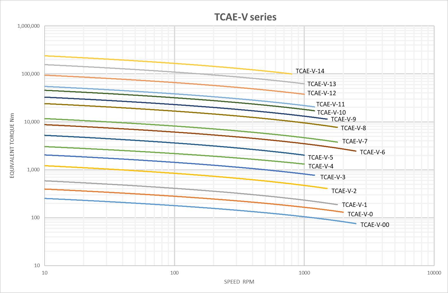
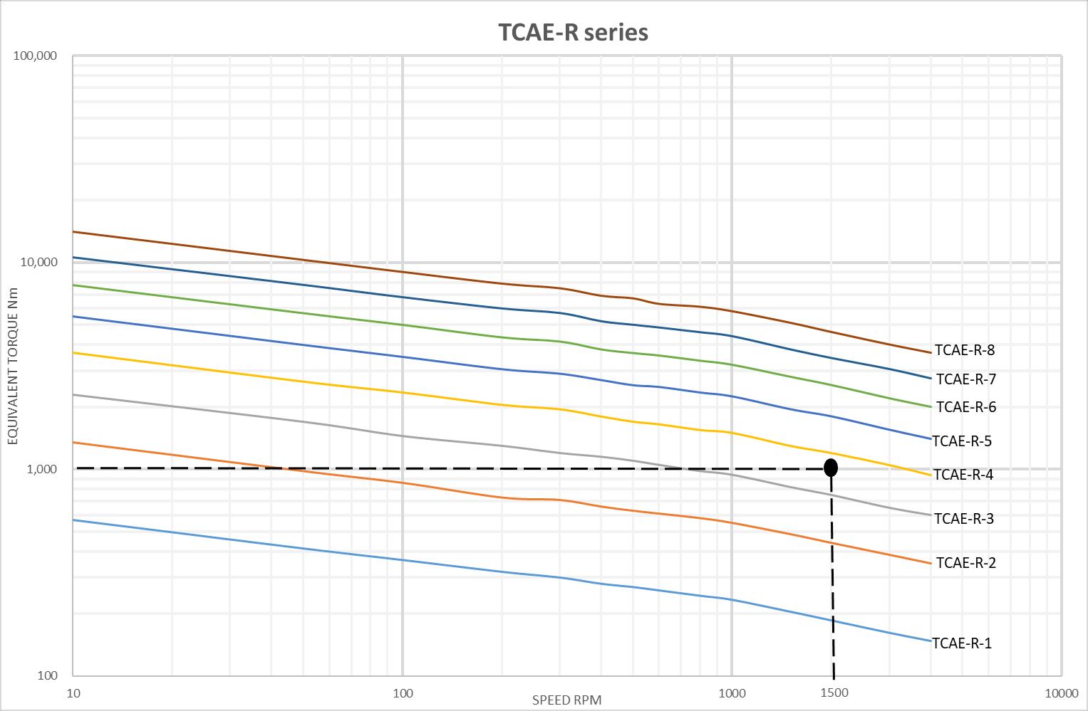
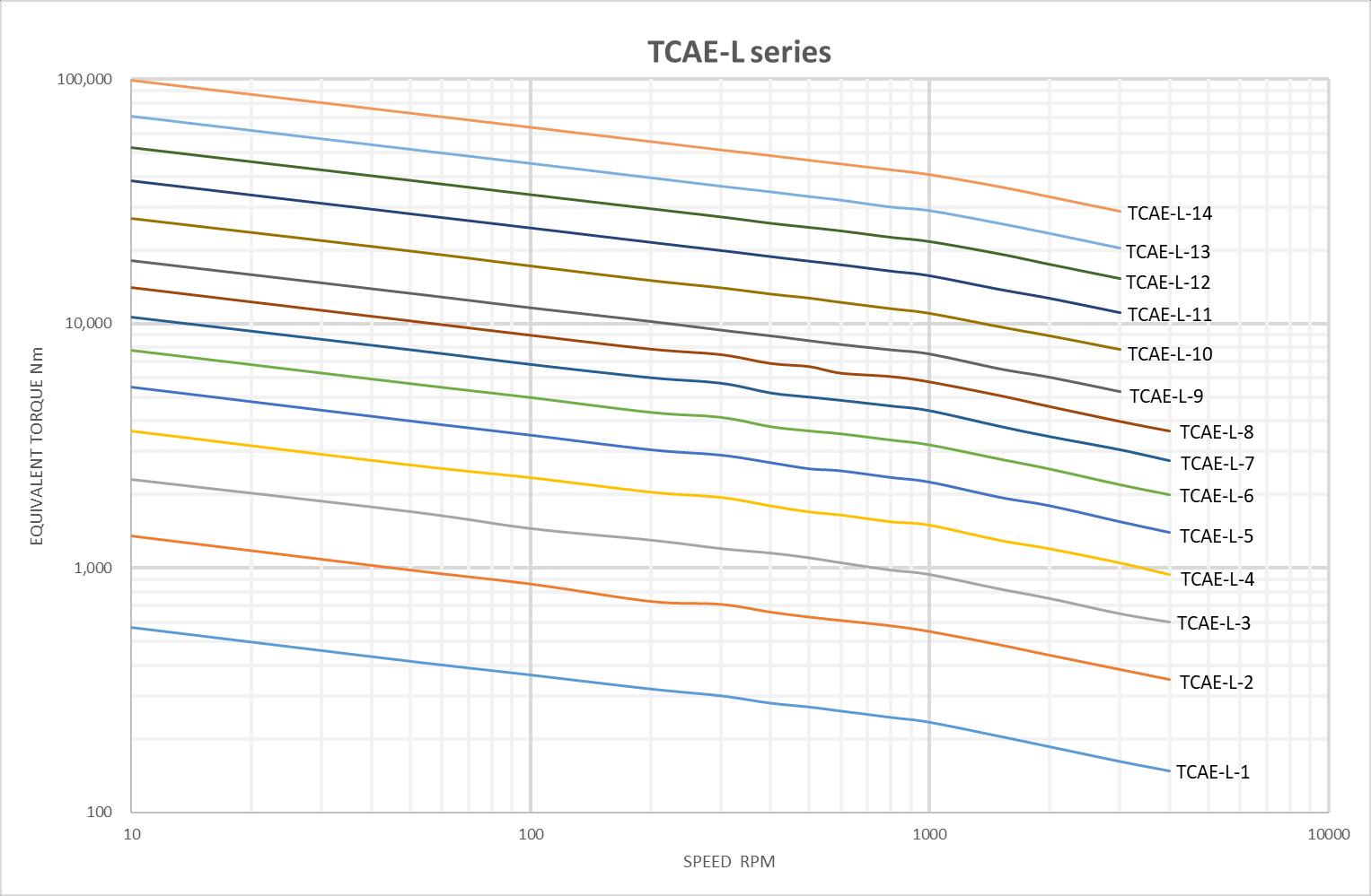
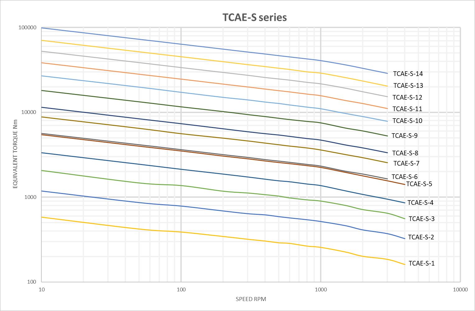
j. Determine the series of coupling required for the application (R, L, V, S) usually based on the distance between shaft ends (DBSE). Using the appropriate chart below for the required coupling series, position the intersection of the Equivalent torque Te and the coupling speed,
RPM
k. The selected coupling is found at the line above this intersection point. l. Example: The Equivalent Torque Te has been calculated at 1,000Nm and runs at 1,500 RPM and due to the DBSE required an TCAE- R series is selected. Following the graph for R series a size TCAE-R-4 coupling is chosen to fulfil the requirements (Page 8). m. These graphs for each TCAE series represent the coupling service life of 7,200 hours (equal to 8 hours per day, 25 days per month for 3 years) n. For applications requiring more intricate operations and different service lives it is recommended to use the Spreadsheet Selector Program.