3 minute read
DIY USB Hub Power Supply

As the USB ports from a laptop or computer can only source 500 mA of current there are times when the hub needs to be plugged into a wall-wart or other power source. If there are mains near the telescope then a wall-wart is fine. If not then using an inverter for something like a USB hub is over-kill.
The best way to power the hub is to use the 12 V that I have on hand.
Advertisement
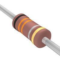
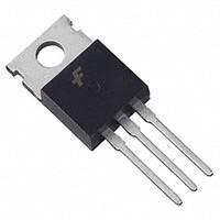
For this project I used an LM7805 three-terminal positive voltage regulator (Figure 169). These are very handy chips that have onboard short-circuit, over-temp and over-current protection. They come in various output voltages and can handle a 1 ampere load. With large loads they can develop a lot of heat.
About Heat
The 7800 series chips on their own get hot... sometimes very hot. They heat up around 65 C° for every watt of current that the Fig. 169 parts attached to them draw according to the following equation:
Heat generated over ambient (Deg C) = (Input voltage - Output voltage) * current * Tc
(Tc is the thermal resistance of the chip to ambient... 65 C/W with no heat-sink)
This means that if the input voltage is 13.6 V and your output voltage is 5 V then there is a voltage drop of 8.6 V. If the load is 1 A then the chip will heat up to about 550 C° (it won't really, it would have shut itself down when the core got to about 150 C°).
Fig. 170

There has to be some place for the heat to go: a heat-sink. For a 5 V regulator with a 13.6 V source the part reaches too hot somewhere about 200 mA, for an 8V regulator about 300 mA (I have used a bare 7808 to power my Canon T1i): both of these with no heat-sink. This is the 65 C°/W 'thermal resistance to ambient' value of the part. If we add a heat-sink then this value changes and the thermal resistance becomes
140
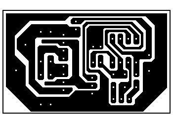
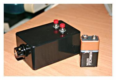
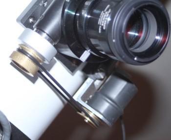
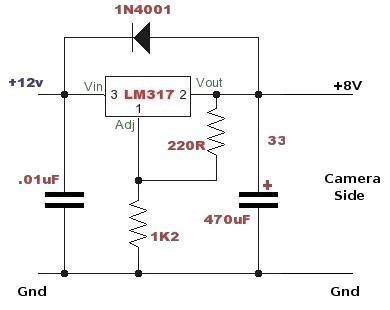
that of the heat- sink. So a 10 C° /W heat sink will allow our 5 V part to handle a load of about 1.75 A (higher than it's rated for) In this case, the heat-sink will be very hot but the regulator won't burn up. For this converter I used a very large heat-sink from a 486 or Pentium (I can't remember) computer that, if I remember correctly, was rated at about 3 C°/W. At full load it should only get to about 25 C° above ambient. Firstly a hole was drilled and tapped into the back of the heatsink and the 7805 regulator was screwed tightly onto it. Thermal grease should be used between the 7805 and the heat-sink if available, it helps. Then the positive lead from the source was soldered to the regulator's input leg and the positive lead to the powered device (USB hub) was soldered to the output leg. The input and output ground leads were soldered together with the regulator's ground leg. A .33 uF capacitor is soldered in place from the input positive to ground. Once this was done it was put into an old project box I had lying around with a suitable cutout made in the box for the heat sink to be able to 'see' the outside air. That's about it. It functions perfectly and, as I mentioned at the top, is very simple. Fig. 171 With a single 7800 series regulator the current limit is 1 ampere. With a 4-port hub it would be nice to provide 500 mA to each port with enough headroom for the port itself. The elegant way to do this would be to use a SimpleSwitcher but there is an inelegant way that is cheap and easy: parallel 7800 regulators. To provide 2.5 A I suggest 4 regulators in parallel. To keep the load balanced a .47 ohm, 1 watt, 1% resistor on each output would work. A .33 uF filter cap on the input and a .01 uF cap (optional) on each output rounds things out. The black common lead in Figure 172 is ground.

Fig. 172

141