14 minute read
RUMPLER TAUBE FULL SIZE FREE PLAN


1 2
3 4
Advertisement
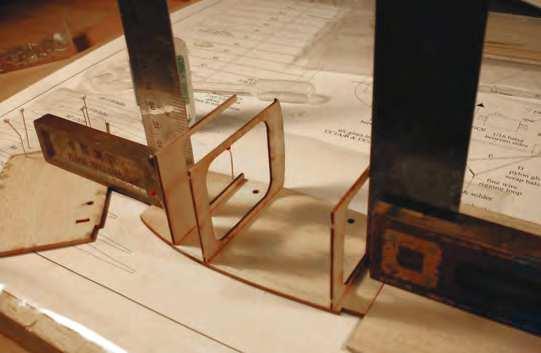
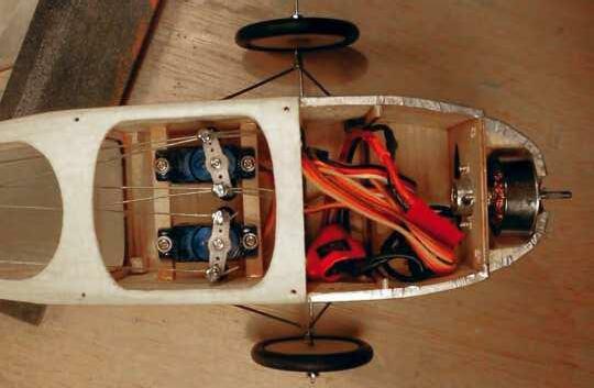
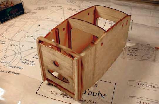
1: Formers glued onto a side squarely help to ensure a completely square forward fuselage section. 2: With the second side added the nose is pulled in onto F1. (see text) 3: A square front end needs a square rear frame too. 4: Quite cramped in there, isn’t it? Sub 5-gram servos are fi ne if you need a little more space.
THE MODEL
Although there is nothing particularly complicated about the build, there are rather a lot of wing ribs to cut. Therefore, I strongly suggest you arm yourself with the set of laser cut parts before starting to build the model. However, for those who insist on ‘cutting their own’, the second sheet of the plan provides all the patterns that would appear as a cut part set, laid out on wood size panels.
To do it the ‘hard way’ therefore, copy this sheet, cut out the panels and LIGHTLY spray-mount them to the wood to create your own print-wood style kit. Once the parts are cut out, because you only lightly stuck the patterns in place, the paper can be peeled away. The motor used on the prototype model provides ample power for far greater-than-scale performance, but the choice these days is even wider than when this design was fi rst drawn up. Just beware of a power mismatch by using an over-powerful motor; the Taube didn’t have unlimited vertical performance! By contrast, a slightly smaller motor would work just fi ne, but would require more nose weight to be added.
So, with the preliminaries out of the way, let’s see about building a model Taube.
WINGS
I always like to build the wings fi rst because I fi nd them a bit boring. In the case of the Taube, the wing panels are a little more interesting than an average wing, but still build very quickly.
The fi rst task is to laminate that elegantly curved leading edge and allow it to dry thoroughly before proceding any further. While that dries, you might as well laminate the bass spars too.
Identify and mark all the individual ribs and glue the reinforcing strips to those that require them, then pin down the spar and leading and trailing edge parts, gluing as required. Add part W1, laminate parts TE5 and prepare to start gluing in the ribs.
Once all the ribs are glued in, including the bass ‘aileron’ ribs, allow the wing to dry before adding the root bay sheeting and hard balsa rigging blocks. It’s worth mentioning here that these rigging blocks should not have the grain vertical; that would be just asking the rigging cables to cut into the grain as it is pulled taut. Trim and sand the blocks to match the rib profi le.
All that then remains is to trim and sand overall, drill the rigging blocks and set the wings safely to one side.
TAIL SURFACES
Once again, building the tail surfaces is all very straightforward stuff . Laminate the outlines and build the surfaces over the plan from strip balsa and cut parts. Once dry, sand overall and round off the edges. Fit the control horns after covering is complete.
Note that the upper elevator cable passes through the tailplane if you use the scale exit position. Therefore, you will need to apply reinforcing patches on the covering where the control cable passes through, or maybe some sort of internal guide. You could also cheat and exit the cable though the top of the fuselage.
FUSELAGE
Now we fi nally come to the interesting part, the construction of the fuselage, which is build as two separate sections. The rear frame is built as one unit and the forward sheet section as another assembly. The two are then joined, the longerons sanded fl ush and the decking added. ▼
5 6
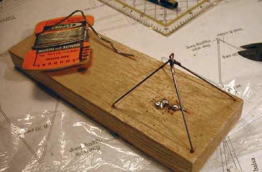
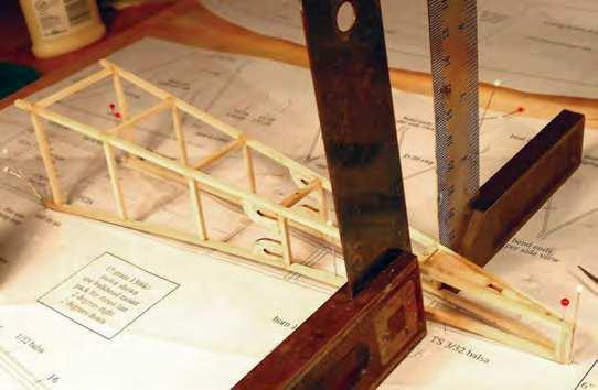
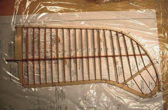
5: Lots of different wing ribs but the wing structure is really quite simple to build. 6: A simple jig aids soldering up the wire parts and avoids the risk of scorch marks on the structure.
Begin by building two rear side frames over the plan. Use hard balsa for the longerons, but medium balsa is perfectly adequate for the uprights and crossbraces. Once completely dry, join the sides with the cross-braces and part TS, making sure you keep everything straight and square.
Join the vertical grain and horizontal grain forward sides and mark them with the positions of formers F2, F3 and F4. Join the sides with these formers, ensuring it all remains square. Pull in the nose and add F1. The vertical grain sections, shown as a part, are adjusted to allow for the curvature of the sides. To help ensure equal curvature, it is worthwhile making a template from the top view. Wet the outside of the vertical sheet, spot glue the template to F2 and clamp the curved sheet to the template.
Allow that to dry and it should result in ready curved sides that are easy to glue to the bevelled edges of F1.
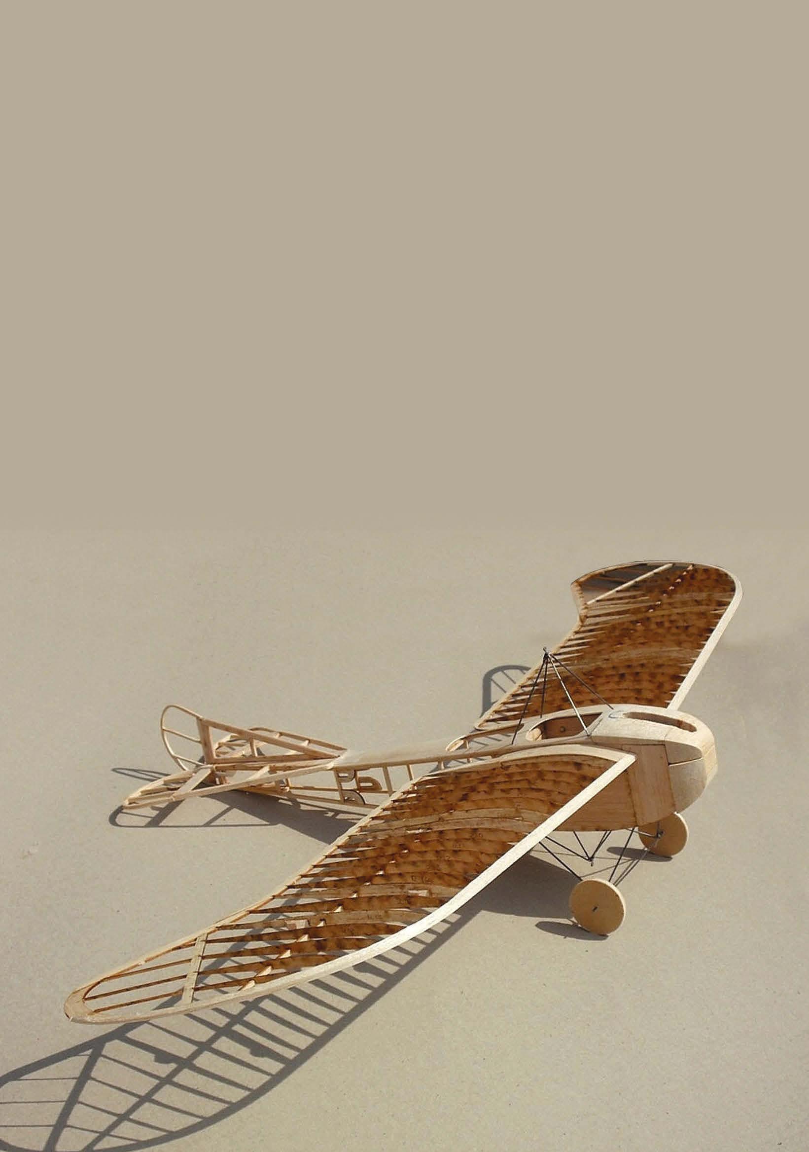
The uncovered model shows off its straightforward construction. Spoked wheels would add interest and woud be a scale option.
Fit the motor mount to F1, packing it to provide the specifi ed down and side thrust.
Laminate the undercarriage parts, glue these inside the fuselage and then join the front and rear fuselage subassemblies. Yet again, take care to ensure the structure remains straight and square.
Sand the longerons fl ush with the sheet parts and fi t the 1/16” balsa fuselage bottom ‘fi ll’ pieces. The grain should run across the fuselage and they should be cut to fi t around parts UC. Now fi t the pylon blocks and, while the top is still open so you can see what you’re doing more easily, drill the blocks for the pylons. If required, also drill out any glue that may have gotten into the openings in parts UC.
Now, you can fi t formers F5, F6 and F7, followed by the 1/32” balsa decking. There are some ‘interesting’ changes of curvature on the decking so I recommend making templates to get the shapes right, applying the panels wet and allowing them to dry to shape before fi nally gluing them in place.
Fit the cable exits, and a scrap piece to reinforce where the strip goes and then tack-glue the nose blocks in position. Note that the front of the nose is split, with the upper section acting as part of the access hatch. After carving and sanding the blocks to shape, it is a good idea to cut a slot in the top so the dummy engine appears to fi t into the nose, rather than being just stuck onto it. Just take care not to make the groove too deep because you still have to hollow out the nose to clear the motor. Once that task has been completed, all that remains to be done is fi nal sanding before cutting out the cockpits and moving on to the wire bending. Since all the wire parts can be fi tted after the model is covered, simply being glued in place, the wire bending is relatively painless. Shape the parts as shown on the plan and make up a simple jig to hold them while soldering. They could, of course, be soldered in-situ on the model but that risks scorch marks if you drop solder on the structure.
COVERING AND FINISHING
Ulrich covered his model using Graupner Ecospan, which a very lightweight material of the ‘Litespan’ variety, with a weight of 30grams per square metre. For this type of model, it is the ideal covering, but any of the lightweight fi lms will also work just as well. Obviously, the full size Taubes had fabric covering over open framework so the covering was not shiny, so the ‘scale ultras’ among us might care to consider heavyweight tissue as a covering medium – at the heightened risk of ‘puncture damage’.
The wings aren’t the easiest things to cover because of the shape, so be very careful not to induce warps as you stretch the covering around the tips. For this reason I would suggest you avoid any covering that shrinks too aggressively.
The nose area was covered using silver fi lm, but may have been better treated to priming, sealing, sanding and painting. Ulrich found that the harsh handling needed to get the covering around the curves where the hatch fi ts onto the fuselage resulted in a less tidy join than he would have liked.
If you do decide on this option, I fi nd automotive fi ller-primer (two or three coats) will sand very smooth using 400-grade wet-or-dry paper and wheel paint gives a rather nice, durable fi nish.
The dummy engine can be as intricate, (or not), as you like and is reasonably easy to produce from bits of dowel and various pieces of scrap. The style shown on the plan suits side radiators, but some Taubes used a header style radiator above the engine. As a point of interest; since the model will almost certainly need nose weight, the header radiator fashioned in hardwood, rather than balsa dowel, will add weight exactly where it’s needed.
How you apply the markings is a matter of personal taste. Ulrich painted his using acrylic paints, but vinyl or homemade waterslide decals would be perfect for those not so skilled at accurate painting. If you do decide to paint them, do so before assembling the model so that you still have relatively fl at, uncluttered surfaces to work on.
ASSEMBLY
Since access to the servos is via the cockpit opening, it is a good idea to fi t the radio gear and install the basic closed loop cables before there are pylons and rigging cables in the way. I would suggest fi tting the ESC to the front of F3 and the receiver to its rear face. 1/4” square hard balsa rails are perfectly adequate for the tiny servos needed in a model of this kind. Note that, unless you chose the option mentioned earlier, both elevator cables exit through the upper tube.
Because it makes the model easier to handle, it’s a reasonable idea to fi t the wire parts fi rst; so the model can sit stable on the undercarriage. These assemblies are simply glued into the holes drilled for them earlier.
Next, the wings can be glued in place. ▼
CUT PARTS SET FOR THE
RUMPLER TAUBE
Get straight down to construction without delay!
This model’s plan is supported by a laser-cut set of ready-to-use balsa and plywood components. This provides all the parts that, otherwise, you would need to trace out onto the wood before cutting out.
IT DOES NOT INCLUDE STRIP AND SHEET MATERIAL OR SHAPED WIRE PARTS
Order set:
CUT336 Price: £39.00
plus carriage: £11.50 (UK), Europe £26.00
Shipping Note: For shipping to destinations outside the UK and Europe, you will be charged our standard fl at-rate price of £49. This covers most destinations and secures your order with us. However, we will contact you accordingly with an accurate total shipping charge prior to dispatch and either issue a refund or a PayPal money request for the balance.
Order online at: www.doolittlemedia.com
Doolittle Media, Doolittle Mill, Doolittle Lane, Totternhoe, Bedfordshire. LU6 1QX • Tel 01525 222573
The spar extensions, along with former F4A, will set the dihedral and should ensure equal dihedral on both wings. Glue the root rib to the fuselage side and the spar extension securely to F4/ F4A. Now use this assembly as a guide to alignment while you glue on the tail surfaces.
When connecting the closed loop cables to the control horns, remember to clamp both elevators together and level with the tailplane before adjusting the cable lengths. Also, make sure the servos are centred before connecting up the linkages.
The cables themselves, similarly the rigging, can be fine, nylon coated beading wire or simply 12 lb. strain monofilament fishing line. On a model like this, the beading wire looks good but is definitely stronger than required. I have used monofilament line on 400 size models without a problem, so it will be fine on this tiddler. The one downside with it is that it needs painting to hide its humble origins.
I find the simplest way to rig these models, without inducing warps, is to use cables that run in a continuous length from the top pylon, through the rigging block and ending at the lower pylon. If you rig the entire model without gluing the cables into the blocks, it is then possible to carefully adjust out any warps, or add washout, should you desire.
Once both wings are identical, the rigging can now be glued into the blocks, thereby locking your setup in position. A small spot of thin cyano in each hole does the job admirably.
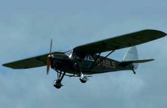
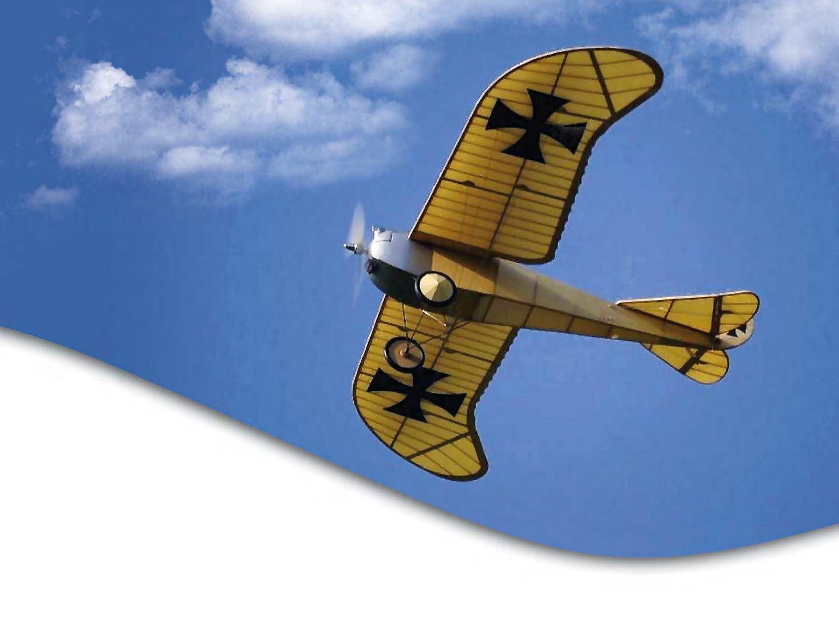
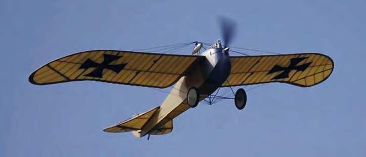
Drifting by overhead on just a whiff of power. Beware of using too powerful a motor - it won’t
make the model fly better.
FLYING
Obviously Ulrich was not a particularly experienced a model pilot because he forgot that on a model which uses the battery to help balance it, fitting a battery half an ounce lighter can lead to some ‘interesting’ moments.
Despite this, he managed the maiden flight very well, without damaging the model. Balanced at the point shown, the model will be a little nose heavy. However, that will make it easier to trim out and the balance point can gradually be moved back as you become more used to how the model flies - just don’t take out half an ounce in one go. On a model that weighs little more than 8 ounces, that would seem to be a bit excessive.
Once the model was balanced correctly, at the point shown, it proved to be a very sedate, stable flying model that could be flown quite slowly. It still required a bit of up trim and quite a bit of elevator to flare for landing, but Ulrich is very happy with it.
Bearing in mind what I said about power, it isn’t surprising that the model climbs quite steeply at much over half throttle, but flies really well on minimal power - a bit like the full-size would have performed if it actually had more power.
However, this type of model is absolutely at its best just gently puttering around the sky, making low, slow passes so you can enjoy watching it float by. So running at reduced throttle settings is perfect.
Roll on those long, calm summer evenings. n
NEW
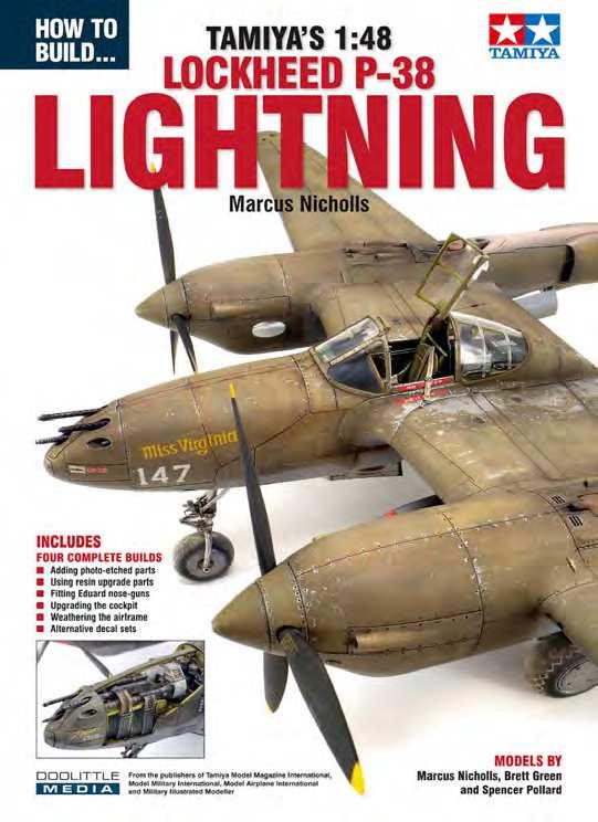
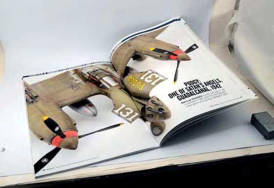
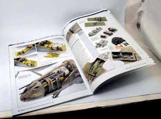
How to Build... TAMIYA’S 1:48 LOCKHEED P-38F/G LIGHTNING
By Marcus Nicholls
The Lockheed P-38 Lightning is an iconic US fighter from the Second World War. Its twin Allison V12 engines were mounted in booms to free-up the nose so it could house a fearsome array of four M2 Browning machine guns and a 20mm cannon. The twin-boom airframe became a sight feared by enemies wherever it served, with good reason. In 2019, after several years of painstaking research, Tamiya released an all-new kit of this sleek aircraft and it has taken its place proudly in the 1:48 Aircraft Series as No.120 in the range. In this new ‘How To Build’ book, Tamiya Model Magazine’s Editor, Marcus Nicholls, presents no less than four built-up examples of Tamiya’s fantastic model; one Lightning each from Brett
Green and Spencer Pollard, plus two from Marcus Nicholls.
The second of Marcus’s models incorporates resin and photo-etched super-detail sets from
Eduard, showing how they can be used within the build to take the detail to an even higher level. New photos of the other models show how Brett Green and Spencer Pollard built and painted the models in their own styles.
The book includes four complete builds, covering the following topics: n Adding photo-etched parts n Using resin upgrade components n Extending the nose undercarriage leg n Upgrading the cockpit detail n Weathering the airframe n Alternative decal sets
MODELS BY
Marcus Nicholls
Brett Green
Spencer Pollard
NOW IN Only £15.95 plus p&p STOCK
Also available