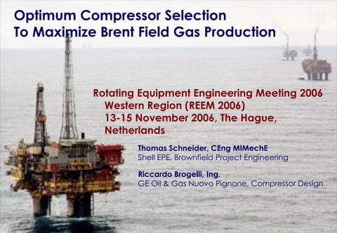
Optimum Compressor Selection To Maximize Brent Field Gas Production
Rotating Equipment Engineering Meeting 2006 Western Region (REEM 2006) 13-15 November 2006, The Hague, Netherlands Thomas Schneider, CEng MIMechE Shell EPE, Brownfield Project Engineering
Riccardo Brogelli, Ing. GE Oil & Gas Nuovo Pignone, Compressor Design
Optimum Compressor Selection To Maximize Brent Field Gas Production
• Changing Operational Requirements • Compressor Design Challenges • Brownfield Construction Challenges
• Questions
Brent Field STOIIP = 3800 MMstb GIIP = 7500 Bscf
N
140 m
2.5 km
500 km
50% Shell 50% ExxonMobil
15 km
5 km
Brent Field Production Profile 1982 : Start of gas export
1997 : Start of depressurization
Compressor Optimisation Opportunity
gas oil
1975 1980 1985
1990
1995
2000
2005
2010
Brent Reservoir Pressure Brent Reservoir Pressures @ Datum (8700fttvdss) 6000
Value Proposition:
5000
Ultimate gas recovery
+ 1 Bscf / psi
Pressure [psi]
4000
reduction in ultimate reservoir pressure
3000
Ultimate Pressure: Base = 1650 psi LPO+EV = 1300 psi LPOP = 1150 psi
2000
1000
Brent B1 Brent B2 Brent B3 Brent B4 Target
Start depressurization
0 1976 1978 1980 1982 1984 1986 1988 1990 1992 1994 1996 1998 2000 2002 2004 2006 2008 2010
Brent Late Life Strategy Map Brent B
Platforms Brent C
SEGAL Brent D
Onshore Compression Reduce “Mini” suction “Mini” suction “Mini” suction FLAGS booster booster booster Pressure Do “Matched” “Matched” “Matched” Nothing Suct. booster Suct. booster Suct. booster Tie-back
Tie-back
Tie-back
Replace HP Replace HP Replace HP Compressor Compressor Compressor Do nothing Discharge Booster
Do nothing
Do nothing
Strategies : No Further Investment Lowest Cost LPOP OPEX Reduction 3rd Party Processing Maximum Recovery Enhanced Voidage Not Feasible
Concept (a) – BD/BB/BD LPOP upgrade Concept (b) – BC LPOP Hub / BB+BD Tie-back
“Mini” suction booster optimally sized for expected late life production. “Matched” suction booster optimally matched to existing HP compressor.
Brent Late Life Concepts BC
BB
Concept (a): “High Head” LPOP Replacement Compressor on BB, BC & BD:
BA
BD
Penguins
FLAGS
LiftGas
Concept (b): “Matched” LPOP Suction Booster on BC, Wellstream Tie-back of BB & BD
BA
EV
BB
BC
EV Power + Comms
FLAGS
BD
Penguins
EV Power + Comms + LiftGas
Gas Export Compression Train HP1 Suction
HP1 Discharge
GEARBOX MAAG GB-50
HP2 Discharge
GAS TURBINE DRIVER RB-211
HP2 Suction
CENTRIFUGAL COMPRESSOR NUOVO PIGNONE 2BCL506-8/A
~ 2.2 m
~30t
FOUNDATION
~ 4.6 m
Brent LTFD Gas Process Scheme Lift Gas to wells
V-49400 (HP1)
V-49400 V-49400 (HP2)
TEG Contactor V-49600
Gas Export To FLAGS
E-49171
HP wells
E-49181
E-49191
HP Separator V-42100
K-49300 (LP1)
x2 EV wells
K-49300 (LP2)
x2
LP Separator V-42120 E-49140/45
Oil Storage/Export
LP flare k/o drum
E-49150/60
Process Verification “Minimize Change” • Changes to actual volumetric flow – Some recycle valve and LCV resizing
– No piping or vessel changes – manage increased velocity
• Changes to pressure – TEG contactor – reduced efficiency requires stripping gas
– LP compressor - decoupled using discharge throttling valve – Fuel gas supply assurance – trip logic changes – No change to relief pressures
• Increase in compressor discharge temperatures – Process cooler re-rating – heat transfer capacity essentially unchanged – Piping and valve rating – change to valve seat/seal materials – Pipe stress analysis - modified HP1 discharge spool geometry
– Instrumented protection (SIL) - added cooler high temp trip
Brent HP& Compressor OperatingEnvelopes Envelopes Brent Inflow Compressor
HP1 Suction Flow [10^6 scm/d]
14 12
HP2 Discharge 140 bar-a Mol Weight 21 kg/kmol
10
Approx Brent gas inflow capacity (with gaslift)
Year 1997
Year 2000
8 Year 2003
6
Gaslift
Year 2006
4
HP1
Export
HP2
2 HP Sep
Fuel Gas
0 5
10
15
20
25
30
35
HP1 Suction Pressure [bar-a]
40
45
Brent HP& Compressor OperatingEnvelopes Envelopes Brent Inflow Compressor
HP1 Suction Flow [10^6 scm/d]
14
HP2 Discharge 140 bar-a Mol Weight 21 kg/kmol
12
original
Year 1997
10 Year 2000
rewhee l
8
Year 2003
6
upgraded (subject of this presentation)
4 2
Gaslift
Year 2006
HP1
HP Sep
Export
HP2
Fuel Gas
0 5
10
15
20
25
30
35
HP1 Suction Pressure [bar-a]
40
45
Brent HP CompressorEnvelopes Operating Envelopes Brent Compressor 20
compression ratio
15 upgraded 10
rewheel 5 original mol weight: 21.1 kg/kmol suction temp: 30 degC
limited to max 27 MW power
0 5
10
15
20
1st stage suction flow [103 acm/d]
25
Brent Compressor Comparison Original (2BCL506/A) 35 / 140
Rewheel (2BCL506/A) 20 / 140
Upgraded (2BCL506-8/A) 8 / 140
Polytropic Head 1st / 2nd stage (m)
~8500 / 8100
~13000 / 11800
~21000 / 18500
No. of Impellers
3+3
3+3
4+4
Bearing Span (mm)
1953
1953
2166
Max. Continuous Speed (rpm)
8085
9083
9508
600
630
630
Psuct. / Pdisch. (bar-a)
Impeller Diameter (mm) Impeller Material
ASTM A182 Gr F22
ASTM A705 Gr 630
X5CrNi16.4 (Virgo 38)
Upgraded Compressor Rotor / Stator Bearing Span = 2166 mm Rotor Weight = 1310 kg
MCS = 9508 rpm
Optimum Compressor Selection To Maximize Brent Field Gas Production
• Changing Operational Requirements • Compressor Design Challenges • Brownfield Construction Challenges
• Questions
Upgraded Compressor Design Brief Objectives Maximize head Wide operating range
Materials suitable for sour duty
Constraints Same shaft centre-line & base plate as original compressor Crane constraint - Casing weight lower than 18T Nozzle loads up to 5x NEMA
Casing Design Optimisation
Reduced thickness at HP2 suction end
High thickness where necessary
Low thickness where not necessary
GE NP Patent: eccentric casing
Inlet Volute Optimisation
original
improved
Impeller Design Optimisation Full factorial DOE on axial symmetric FEA
VERIFICATION Phase: final 3D check
Design References – Kirk-Donald • K-D used to compare rotor-dynamic criticality of similar designs • All Brent compressors in “warning zone” • Upgrade compressor criticality reduced by increasing shaft stiffness • Risk compounded by not having a string test ➔ complete rotordynamic computational analysis required
max continuous speed first critical speed at infinite bearing stiffness
Pd = discharge pressure Ps = suction pressure
Undamped Critical Speed Map • 1st critical speed far below operating speed range → highly flexible rotor • 2nd critical speed in zone of MCS - but highly damped
1st Critical Speed – Field Results NDE Bearing
1x Amplitude [m]
A.F.=1.76 1st critical speed = 3500 rpm
Shaft speed [rpm]
Compressor Seal Detail HP2 Impeller eye labyrinths swirl breaks
Shunt holes Interstage Tapered Honeycomb
HP1 Impeller eye labyrinths swirl breaks
Honeycomb Taper Selection Brent Compressor Stability vs. Center Seal Divergence (Nominal Bearings) at maximum continuous speed and maximum pressure ratio
2nd stage discharge
1st stage discharge
Interstage Diaphragm Deformation Ambient temperature
Honeycomb seal
Flow Intermediate Balance drum
Differential movement of Inter-stage diaphragm From cold to hot
2nd stage discharge
1st stage discharge
Interstage Diaphragm Deformation Increasing temperature
Honeycomb seal
Flow Intermediate Balance drum
Differential movement of Inter-stage diaphragm From cold to hot
2nd stage discharge
1st stage discharge
Interstage Diaphragm Deformation Increasing temperature
Honeycomb seal
Flow Intermediate Balance drum
Differential movement of Inter-stage diaphragm From cold to hot
2nd stage discharge
1st stage discharge
Interstage Diaphragm Deformation
Differential movement of Inter-stage diaphragm From cold to hot
Maximum temperature
(hot) 0.10 mm
Honeycomb seal
0.44 mm (cold)
Intermediate Balance drum
Flow
90 mm
Honeycomb Clearance Check - Seal in “cold’ condition - Running at 1st critical speed - Vibration at alarm limit
vibration orbit “inlet clearance” (0.70 mm) 0
“cold outlet clearance” (0.60 mm) “hot outlet clearance” (0.26 mm)
Optimum Compressor Selection To Maximize Brent Field Gas Production
• Changing Operational Requirements • Compressor Design Challenges • Brownfield Construction Challenges
• Questions
Construction Challenges 1. Minimize duration of shutdown and production deferment
2. 18t weight limit on boat-to-platform lift due to crane capacity 3. Safely manoeuver 35t compressor through a congested module and lift onto existing elevated baseplate 4. Install 32 pre-fabricated spools without hotwork, ensuring stress-free alignment with existing tie-in points
5. Perform offshore performance / stability trial of new machine
Brent Platform Replacement Process Module (RPM) installed by LTFD Project. Access to gas comp on Level 2
Brent Charlie
West crane (boat-to-platfom Max lift 21 t)
Brent Compression Module HP Compressor
Compressor Assembly Trials Casing Lift
Bundle Lift
Compressor Assembly Frame
Mechanical Handling (1/4) Temporary gantry frame with pneumatic hoists/trolleys New HP gas compressor
LP gas compressor Old HP gas compressor Temporary rail system (for load distribution) Empty compressor cradle
Mechanical Handling (2/4) Before shutdown: Install rail system
During shutdown: Install gantry and hoists for compressor lift
Live process piping
After removal of piping
Mechanical Handling (3/4)
Mechanical Handling (4/4)
Piping Dimensional Control
Laser Scan Survey (Point cloud image)
Clash Checks CLASH CLASH CLASH CLASH
CLASH
Gantry and Hoist System Trials
Pipe spool removal
Compressor Installation (1/3)
Compressor Installation (2/3)
Compressor Installation (3/3)
Completed Installation
Conclusions • Business case to lower suction pressures and maximize Brent gas production in late life • Two-step upgrade minimized risk and lifecycle cost
• Technical innovation enabled GE-NP to conceive limit state compressor designs not possible earlier • State-of-the-art modeling and verification gave confidence to install upgrades without string test • Attention to planning, practice and procedures overcame brownfield installation challenges
How NOT to replace the Brent compressor … (Safety Awareness Posters illustrate hazards of the various activities)
3
1
2 In shutdown: remove pipes & install gantry
pull compressors over rails
5
Pre-shutdown: assemble compressor & install rails in module
4 reinstate & commission
lift compressors using gantry
Optimum Compressor Selection To Maximize Brent Field Gas Production
• Changing Operational Requirements • Compressor Design Challenges • Brownfield Construction Challenges
• Questions
Optimum Compressor Selection To Maximize Brent Field Gas Production 9th European Fluid Machinery Congress 23-26 April 2006, The Hague, Netherlands
Thomas Schneider, CEng MIMechE Shell EPE, Brownfield Project Engineering Riccardo Brogelli, Ing. GE Oil & Gas Nuovo Pignone, Compressor Design
Brent Projects Team Members
Gantry and Hoist System Trials
Control console with load gauges for each hoist
Rail and Cradle System Trials
Rail and Cradle System Trials View from inside module (looking to entrance)
Pneumatic pulling hoist attached to pad eye
View from entrance (looking into module)
LPOP 2BCL508/A stator – HP2 Honeycomb Impeller eye labyrinths labyrinth seal with swirl breaks Shunt holes
Honeycomb Induced Instability Kxx Stiffness Kxx vs Frequency 1.00E+08
Pre-swirl 5.00E+07 0.5 0.4
0.00E+00 0
2000
4000
6000
8000
10000
12000
0.2 0
-5.00E+07
-0.2 -0.4 -0.5
-1.00E+08
-1.50E+08