120 minute read
PWI events for your diary

by The PWI

PWI events for your diary August - December 2020
COMMUNITY CAMPAIGNS AND SOCIAL EVENTS
Advertisement
SECTION MEETINGS, SEMINARS, EXHIBITIONS, PRACTICAL EVENTS AND SITE VISITS
TRAINING COURSES, PROFESSIONAL REVIEW INTERVIEWS AND REGISTRATION WORKSHOPS, AND JOURNAL DEADLINES


EVENT LOCATIONS
Please refer to the website for the latest updates of event locations and online options utilising user-friendly platforms.
Beating Covid-19 one click at a time! Attending events counts towards your CPD. So does writing an article for the Journal!
AUGUST 2020
15 August JOURNAL DEADLINE Please send articles to journaleditor@thepwi.org
17 August COMMUNITY CAMPAIGN PWI Engineering Kids Day
24-28 August COMMUNITY CAMPAIGN PWI International Week
SEPTEMBER 2020
3 September SECTION MEETING – EDINBURGH Photogrammetry in Rail (Colin McAteer, Programme Manager (BIM), Network Rail).
7-10 September TRAINING - PWI TRACK ENGINEERING DIPLOMA MODULE 1
7-11 September COMMUNITY CAMPAIGN PWI Careers Week
8 September SECTION MEETING – NORTH EAST Metro Bridge Replacements (Grant Wellford & Duncan Manning, Nexus Renewals Team)
8 September SECTION MEETING – CROYDON & BRIGHTON Track Worker Safety in Rail Accident Investigations (Mark Young, Human Factors Specialist, RAIB) 9 September SECTION MEETING – THAMES VALLEY DLR - meeting challenges, today and in the future (Roger Anto - Track Assurance Engineer, KAD)
9-10 September RAIL LIVE Stand J3, Quinton Rail Technology Centre, CV37 8RP. BOOK HERE: www.raillive.org.uk
10 September SECTION MEETING – BIRMINGHAM The Journey from Asset Management to Maintenance (Rebecca Fasham, ATME Banbury, Network Rail)
14 September SECTION MEETING – SOUTH & WEST WALES Gauging RILA: Rail Infrastructure Alignment Acquisition (Craig Havard, Senior Route Gauging Engineer, Network Rail Wales Route)
16 September SECTION MEETING – GLASGOW UAV Surveying and Modelling (Gerald Brown & Kevin Bryce, Ariel Mapping Solutions)
16 September PROFESSIONAL REVIEW INTERVIEWS 173-177 Euston Rd, London NW1 2BJ (Professional Review Reports must reach us at least six weeks prior to your preferred interview date)
17 September TECHNICAL SEMINAR - AUTOMATED RAILWAYS: Part 1. Online
OCTOBER 2020
6 - 8 October TRAINING - S&C REFURBISHMENT Part A
7 October SECTION MEETING - THAMES VALLEY In-Possession Approvals of Rail Plant (Sam Barrett, Senior Engineer, Aegis Certification Services)
8 October TECHNICAL SEMINAR - AUTOMATED RAILWAYS: Part 2. Online
8 October SECTION MEETING – EDINBURGH Next generation cast manganese crossings verified by computer modelling and unique physical testing (Hannah Persson, Progress Rail).
12 October SECTION MEETING – SOUTH & WEST WALES Infrastructure Asset Transfer for South Wales Metro (Colin Brading, Transport for Wales).
14 October SECTION MEETING – EXETER The good old days! A look at safety (Mark Woollacott, Project Engineer, Network Rail)
Mid October JOURNAL DELIVERY To members
20 October SECTION MEETING – WEST YORKSHIRE HS2 (Gareth Dennis, Senior Permanent Way Engineer, Arcadis) 21 October SECTION MEETING – GLASGOW Professional Development and Registration (Dr Brian Counter, Technical Director, PWI)
20 - 22 October TRAINING - S&C REFURBISHMENT Part B
LATER IN 2020
SECTION MEETINGS Please refer to the website
4 November TECHNICAL SEMINAR - PLANT AND MACHINERY: Support to rail infrastructure renewal and maintenance for the 2020s and beyond. Swindon Steam Museum
9-12 November TRAINING – TRACK ENGINEERING DIPLOMA MODULE 3
15 November JOURNAL DEADLINE Please send articles to journaleditor@thepwi.org
1 December TECHNICAL SEMINAR - SAFETY: On track for a safer railway. Institute of Physics, London
16 December PROFESSIONAL REVIEW INTERVIEWS 173-177 Euston Rd, London NW1 2BJ (Professional Review Reports must reach us at least six weeks prior to your preferred interview date)
andy2
Andy Packham and Andy Steele, PWI Technical Content Managers, give their viewpoints on all things railway.
PWI Technical Content Manager’s (TCM) Andy Steele (left) and Andy Packham (right) source interesting high-quality technical papers and content for the PWI Journals, textbooks and other printed and online media.
They also arrange PWI seminars and training courses, packing them with relevant technical content, delivered by presenters who have great knowledge and a passion to share it.
Do get in touch with us if you have a potential Journal paper to contribute or if you would like to present at one of our seminars. We’d be delighted to hear from you! Also, if there are particular subjects you want covered in the Journal or at a seminar, please let us know.

As I write, we are entering the eighth week of lockdown and I sincerely hope that if like me you have been in self-isolation, that you are staying fit and healthy - and just as importantly sane. Those of us who have been working from home have been learning new technology such as Microsoft Teams and Zoom. I have found the online meeting to be a revelation and when this threat has passed, I feel that the way we work will have changed forever.
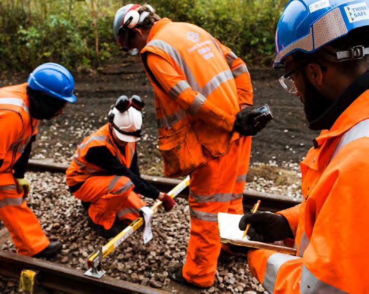
But of course, for so many of our membership, the lockdown has meant “Business as Usual” and you have been working hard to complete the necessary maintenance and renewals projects essential to keeping the railway operational. Our railways ensure that our shops are filled with food and drink, and that NHS frontline staff and other keyworkers can get to their places of work and protect the public. Many hundreds of you have played your part in this and you should be commended, and in this journal and via our social media channels you will see that we are celebrating your contribution in our #HighVisHeroes campaign.
Whilst many of you are working from home and on-site, many of the agency workers who support our industry have seen a significant reduction in available work. My local foodbank informs me that they are experiencing an increase in the use of their services due to redundancies whilst simultaneously seeing a drop in their donations as we all stay indoors. May I ask you to consider donating to your local foodbank if you possibly can? Most foodbanks, but by no means all, are connected via the Trussell Trust who can be contacted via www.trusselltrust.org.
Andy Steele
Technical Content Manager
Permanent Way Institution andy.steele@thepwi.org A great piece by Andy S and as I write, I have just attended the first of the PWI’s online SPOLKS that he organised. Nice work Andy and all the folks who have shared their experiences at this!
It is fascinating to hear how railway engineers are responding and innovating to meet the current challenges and overcome a new set of constraints, making sure the railway stays operating while at the same time maintaining the safety standards that are vital to us all. It’s interesting that safety challenges can drive innovation and that, in turn, this so often results in improved efficiency. Everything has to be thought out in more detail to be properly joined up, planned and have safety and efficiency built in.
A few years ago, when I was a company Transformation Director, as part of the role, I oversaw the Quality Safety and Environment (QS&E) function. I must admit, I was surprised at how engaged and fervent I became about promoting improvements in these areas. For example, as part of our push on behavioural safety, a system was set up that made it really easy for every person in the company to report the slightest safety risk, near miss or (much, much less often) incident. People really engaged in this, sending in simple one or two-line reports submitted electronically through the company intranet, knowing that at least one senior person within the company would read it promptly and that it would definitely be followed up on. The follow up engagement was brilliant, and most times not only resulted in the safety risk being mitigated, but also led to a more efficient way of working being introduced, suggested by staff members and with full buy-in from the team.
I guess that now, more than ever, this sort of teamwork and engagement is needed to solve problems in how to work and overcome the new challenges posed by Covid-19 that are facing us. In the end, it might just cause improvements we never would have thought of making before!
Andy Packham Technical Content Manager
Permanent Way Institution andy.packham@thepwi.org


New website project kickoff
After many months of research, the proposal for a new PWI website was recently approved by the PWI Board. This means that the Operations and Marketing Teams will now be embarking on an exciting web development project with a partner agency, collaborating to build our brand new site.
The project will bring together all of the amazing online activities and resources that the PWI team and community have been involved in over the last few months, creating a more dynamic, modern and user-friendly space.

From the Technical Director
OUT AND ABOUT - Well, what a unique and challenging spring and early summer for me as Technical Director through the Covid-19 pandemic. Just as our dedicated railway staff were able to rise to the challenge of keeping railways and tramways operating, we in the PWI Executive Team have done very much the same to support the industry. I would say that we have been blessed with the development of amazing video technology that has enabled us to communicate as well, if not better, than before.
The future will be different, no doubt, so we will make the most of it and enjoy future travelling to well-attended PWI technical seminars to learn, network and socialise. The PWI code of conduct is all too relevant for us today and as I prepare my ethical session for Module 1 of the PWI Diploma, I will be emphasising how proud I am of the PWI and Engineering Council for its absolute commitment to equality, diversity and inclusion. We have wide open doors internationally and are enhanced by our rich mix of cultures which help us to improve railways.
VIRTUAL MEETINGS TECHNICAL SEMINARS
AND EVENTS - We have maintained our technical Section meetings well with great efforts through virtual technology and numbers have been great. Life will never be the same again and we have to consider how we plan a blended approach to local meetings and webinars in the future.
Andy Steele did a great job with the SPOLKS seminars and Joan Heery, Stephen Barber and I chaired the three sessions with three speakers. It is incredible the way organisations have responded to continuing their work in the crisis and finding innovative ways of carrying out essential infrastructure work. I was very impressed by the focus of railway staff to come to work and accept new ways. These are all on the website.
Sadly, we lost 2020’s PWI Glasgow seminar, Infrarail, Rail Live and a number of international conferences, particularly those in Europe and America. Railways 2020 in Spain, supported by the PWI, is the conference organised by Prof. Joao Pumbo from University of Huddersfield and has been postponed to September 2021. PWI TECHNICAL BOARD - On 29 April we held the Technical Board using the ‘Gotomeeting’ online format with excellent attendance and with very positive feedback. The meeting started on a sad note as the group were informed of a track fatality at Roade, Northamptonshire; further details will follow at the next meeting.
James Andrew from Amey Consulting presented the details of the degree apprentice scheme which they launched in March. They have recruited 30 new starters with A-Levels or equivalent to commence on part time degrees at Sheffield Hallam University. There are over 20 trainee track engineers who have joined as student members, thereby indicating the future. Amey would like these to become PWI IEng.
David Godley from Network Rail talked about registration, capability and competency in the context of rail infrastructure management. He was keen to work with the PWI especially at EngTech level where they had a small number, currently less than 100, and probably three to four times as many chartered engineers. There should probably be four EngTechs for every CEng, which means they could easily have 1000 Engineering Technicians! David indicated that he is keen for us to work with his team to map our training courses against their competency framework.
Joan Heery presented her findings on her discussions with PWI Corporate Members, particularly in the area of their support and requirements. There was a good mention of young people and development, particularly training. One of the most important aspects was a review of the benefits of meetings such as the Technical Board.
AND FINALLY…l’ll finish with two examples of where we as PWI members can make a difference, working to get new technology right and caring for the environment!
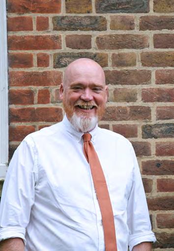
On-site induction welding was demonstrated at Rail Live last year in Stratford-upon-Avon. Trials are developing well and those involved are convinced it will make a difference by speeding up welding on renewal jobs. (Image 1)
Image 2 - Michelle Mabbett, PWI Marketing Consultant, as part of her excellent work on positive themes for the PWI has mentioned the recent Environment day. So, I thought I would include this example of a railway turtle duct, on the right, in the hope that it will deter them from sleeping between the switch and stock rail! Now, who can tell me which country it is? (Image 2)
Please see page 46 - YOUR CAREER - for articles on Degree Apprentice training and Virtual Classroom Training.
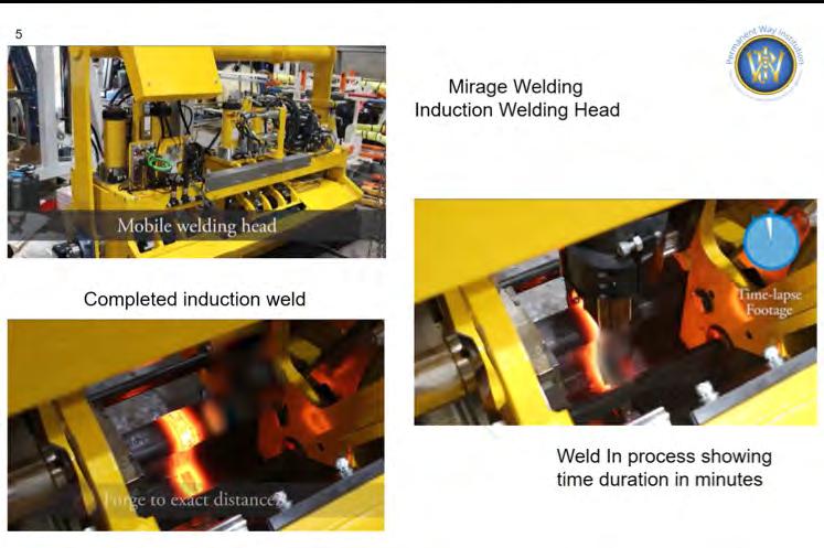
Image 1: Mirage induction welding
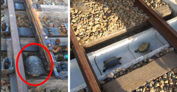
Image 2
Brian Counter Technical Director
Permanent Way Institution technicaldirector@thepwi.org
Namibia railway upgrading works and some unique modular track system construction
Railway operations in Namibia are provided by TransNamib Holdings Ltd formed in 1998, and wholly owned by the Government. Namibia’s rail network consists of 2,382 route-km of tracks. This number continues to increase as the rail infrastructure continues to grow at a healthy rate. Namibia has a history of more than 100 years of railway service. During the colonialisation by the German Empire between 1894 and 1915, a number of railways were built, of which some are still in service today. See image 1.
INTRODUCTION
In preparing this particularly challenging paper returning again to the African continent, making professional and industry contacts and obtaining any real information has proved to be a particular issue! I am indebted to the Namibian High Commission in London who sourced and secured some excellent support for the PWI and me personally.
NAMIBIA
I thought it prudent to spend a little time describing Namibia, its location and history, in order to put the subject of railways in context. Namibia is officially a Republic, and a country within Southern Africa. Its western border is the Atlantic Ocean; it shares land borders with Zambia and Angola to the north, Botswana to the east and South Africa to the south and east. Although it does not border Zimbabwe, less than 200 metres of the Zambezi River separates the two countries. Namibia gained independence from South Africa on 21 March 1990, following the Namibian War of Independence. Its capital and largest city is Windhoek and Namibia is now a member state of the United Nations (UN).
Namibia is a truly spectacular place, with the cool Atlantic breeze to the west and hot deserts to the east. The Namib Desert is an important location for the mining of tungsten, salt and diamonds. The sand dunes, some of which are 300 metres (980 ft.) high and span 32 kilometres (20 mi) long, are the second largest in the world.
Temperatures along the coast are stable and quite unique for these latitudes, generally ranging between 9–20 °C (48–68 °F) annually due to the influence of the cold, north flowing Benguela current of the Atlantic Ocean. Further inland temperatures are variable - summer daytime temperatures can exceed 45 °C (113 °F) while nights can be freezing. The Kalahari Desert is also a large semi-arid sandy savanna extending for 900,000 square kilometres (350,000 sq. mi), covering much of Botswana, parts of Namibia and regions of South Africa. All of this of course truly presents real challenges for railway operations, engineering, construction, inspection and maintenance!
In 1966, South West Africa People’s Organisation’s (SWAPO) military wing, the People’s Liberation Army of Namibia (PLAN) began guerrilla attacks on South African forces, infiltrating the territory from bases in Zambia. After neighbouring Angola became independent in 1975, SWAPO established bases in the southern part of the country. Hostilities intensified over the years. It took, however, until 1990 for Namibia to gain independence. On 1 March 1994, the coastal area of Walvis Bay and 12 offshore islands were additionally transferred to Namibia by South Africa. AUTHOR


Phil Kirkland
CEng MICE, FPWI PWI Vice President (North England Sections)
Phil is an experienced Railway Engineer of 47 years continuous service, beginning in 1973 with British Rail in Newcastle and more recently retiring as Head of Maintenance Delivery at Nexus Metro (Tyne and Wear PTE).
Phil has worked in the rail industry worldwide, specifically in the areas of track inspection, maintenance, renewal, mechanised maintenance, high output systems, railway rules, regulations, policies, processes and all safety matters.
After the independence of Namibia, the Stateowned enterprise TransNamib took control of the national rail network that operates on 3 ft. 6 in (1,067 mm) track gauge, often referred to as ‘Cape gauge’. TransNamib is headquartered in Windhoek and Namibia is well connected in terms of railway infrastructure.
The Rail network stretches from the South (South African border) to the Northern part of the country (Angolan border) and from the middle of the country to its coast and harbour towns. There are aspirations too for new rail links with neighbouring Botswana and perhaps Zambia.

TransNamib operates 2,382 km of route in a country of 825,000 sq.km (by comparison the UK has approx.15,800 km of route in a country of 250,000sq km). While business focus has been primarily on freight services, passenger services are becoming a growing element of the TransNamib business, with the introduction of the timetabled ‘Starline’ passenger services and the ‘Desert Express’ tourist train in 1998, linking Windhoek and Swakopmund. The privately run Rovos Rail ‘Pride of Africa’ luxury train has also reached Namibian rails. Focus is also now on the possible future provision of commuter services perhaps in the capital Windhoek and surrounding areas, and in the north.
The current railway routes within Namibia (see map at image 1) are:
TransNamib freight train approaches Windhoek, Namibia (image: Jon-Erik Munro).
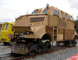
Armoured track inspection vehicle.
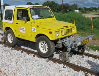
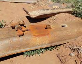
More conventional Suzuki Jimny RRV. Existing steel sleeper T Bolt housing wear.
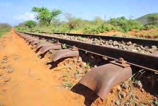
Existing poor quality track assemblies.
(Images above: WCM/D&M Rail Construction and WCM/Rűchel Burkhart). • Windhoek-Kranzberg: 210 kilometres (130 mi) long and completed in 1902.
• Kranzberg-Walvis Bay: 201 kilometres (125 mi) long. In 1914 an extension to Walvis Bay was commissioned; the rails were laid close to the shore of the Atlantic Ocean. In 1980 this extension was replaced by an alternative route behind the dunes that allowed for higher axle load.
• Kranzberg-Otavi: 328 kilometres (204 mi) long and completed in 1906.
• Otavi-Grootfontein: 91 kilometres (57 mi) long and completed in 1908.
• Seeheim-Aus- Lüderitz: 318 kilometres (198 mi) long. The connection between Lüderitz and Aus completed in 1906. The extension to Seeheim was completed in 1908. Eventually the service between Aus and Lüderitz was decommissioned. The line to Lüderitz was reopened in 2018.
• (Uppington) Nakop-Windhoek: 869 kilometres (540 mi) long. The section between Karasburg and Windhoek was completed by 1912, with the extension to Uppington (South Africa) built in 1915.
• Otjiwarongo-Outjo: 69 kilometres (43 mi) long. The first 26 kilometres (16 mi) were completed under the German colonial administration in 1914/1915. The link to Outjo was completed in 1921 under South African rule.
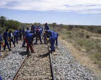
Maintenance rehabilitation works to existing track.
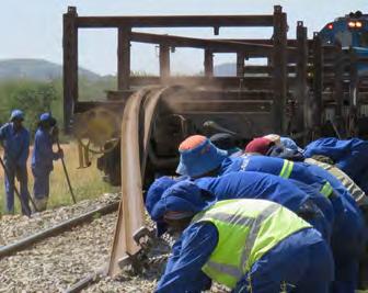
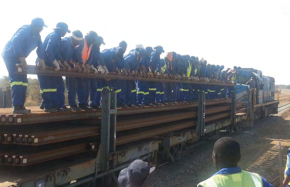
Manually offloading rails. Maintenance rehabilitation works to existing track.


Track renewal bottom ballast – rough grading.

Track Renewal Top ballast – ballast train and hoppers. Track Renewal Tamping and lining –Plasser 07 series.
(Images above: WCM/D&M Rail Construction).
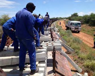
Manually offloading concrete sleepers.
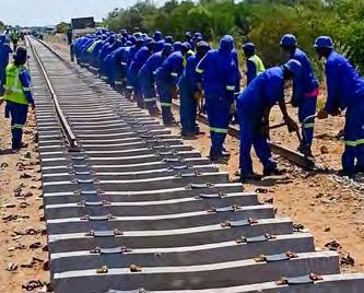
Track renewal manual installation of sleepers and rails.
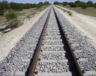
High quality CWR track installation, northern line, Namibia.
• Windhoek-Gobabis: 228 kilometres (142 mi) long and completed in 1930.
• Tsumeb - Ondangwa Oshikango,
Oshakati: commencing in 2005, a new northern extension railway was built between Tsumeb (the existing terminus) to Oshikango and Oshakati approaching the Angolan Border. The project was delivered in three key stages:
1. Tsumeb to Ondangwa 250 Km 2. Ondangwa to Oshikango 59 Km 3. Ondangwa to Oshakati 58 Km
To complete the project, a connection from Oshikango to a point near Cassinga, Angola is planned on Angola’s southern railway system. This new line will link up with the rail system of Angola, (which still needs to be rehabilitated - another Journal article perhaps!) and would enable Angola to export iron ore mined near Cassinga through Namibia via Walvis Bay to countries abroad.
In more recent and very forward-looking times, Botswana Railways signed a Memorandum of Understanding (MoU) in 2015 with its Namibian counterpart state owned TransNamib to facilitate the joint development of the TransKalahari railway which will cost US$ 9.5bn.
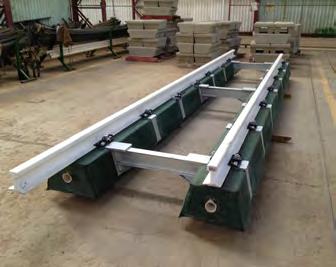
Factory-assembled TMT panel showing cable ducting Image: WCM/T-Track Global Ltd.

TMT (Tubular Modular Track) T-Track system installed on the Aus to Luderitz railway (two images above: WCM/T-Track Global Ltd.). Diagram 1: Comparable construction volumes (image: WCM/T-Track Global Ltd.).
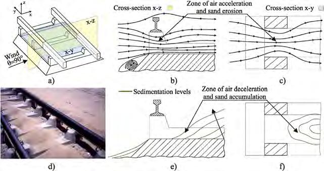
Diagram showing how elevated rail seat sleeper air gap technology works (image: WCM/ K Reissburger).
The likely railway line would traverse the vast semi-arid Kalahari Desert and has the potential to accelerate the development of Botswana’s huge coal reserves, currently in excess of 200 billion tonnes. The line would extend east from the current livestock railhead at Gobabis and excitingly, is likely to be electrified.
The investments in Namibia and its railways have attracted significant funding requirements from a range of sources. Examples of these include loans and borrowings from the African Development Bank, Arab Bank for Economic Development in Africa and the Kuwait Fund for Arab Economic Development. The ExportImport Bank of China signed off a concessional loan for purchasing of locomotives, wagons and infrastructure for the new railway being built in northern Namibia, and China further pledged concessional loans, preferential export buyer’s credit, grants and interest-free loans.
TRACK CONSTRUCTION AND MAINTENANCE
One of the biggest social issues in Namibia is the critical public health issue of HIV/AIDS. While the disease has declined in prevalence, Namibia still has some of the highest rates of HIV of any country in the world. 13.8 percent of the adult population between the ages of 15 and 49 are infected. This is a significant issue and risk for any transient work force (either internal or external) engaged in railway construction works.
There was also a dearth of skills, and the track on much of the network was in poor shape. The railway suffered from archaic systems, embedded in the 60s and 70s. Policies, processes and procedures all needed updating. Computerisation, mechanised maintenance equipment, technical understanding and safety management systems were all very much required, and there is still work in progress. To change would be a slow process and contrary to the current policies as labour in Namibia is so plentiful and inexpensive.
Some of the practices to us as outsiders looking in will seem incredulous and downright unsafe - the fainthearted should look away now! The younger members of the PWI should understand that for many of us here in the UK, when our safety practices were less enlightened, this is how we too actually worked week in and week out! We should not however

CBG (Iran) ltd elevated rail seat concrete sleeper (image courtesy CBG (Iran) Ltd).
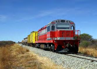
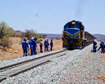
Chinese built SDD6-006 locomotive on muchimproved permanent way, near Otjiwarongo in Namibia (image: Laurie Mulrine).
criticise; as professional PWI members we should share our knowledge, techniques and products wherever possible to ensure continuous improvements, especially in safety matters, around the world.
Namibia Rail Construction was established as a joint venture between TransNamib and D&M Rail Construction (Pty) Ltd with the objective to build local capacity for the maintenance, rehabilitation and construction of all railway infrastructure in Namibia. D&M Rail Construction is the leading permanent way inspection, maintenance and renewal contractor in Namibia, and has been at the forefront of track work upgrades for many years now.
There would appear to be four main strands to PWay engineering activities in Namibia:
• Existing track rehabilitation and maintenance • Existing track complete renewal • New route construction • Industrial sidings and facilities installation and maintenance
The railway line from Kranzberg to Tsumeb covers nearly 400 miles and connects the port of Walvis Bay with the north of Namibia where major industries such as Ohorongo Cement and Dundee Precious Metals (Copper) are located. As a by-product of the copper extraction process, 330,000 tonnes of sulphuric acid is produced annually which is then sold to Namibia’s Uranium mines and transported back by rail to the Walvis Bay area. The line was converted from 600 mm to 1067mm gauge in the 1960s, but built to branch line standards using 30Kg/m jointed flat bottom rails on steel sleepers with through T-Bolt fastening systems and little or no ballast. Rails were anywhere between 12m (40ft) and 36m (120ft), joined by fishplates that allowed for expansion and contraction.
As was standard then in South Africa, expansion gaps up to a maximum of 15mm were applied to allow for thermal movement of the rails. Such rail joints reduced the risk of lateral track buckling at high temperatures, and also reduced the risk of rail breaks during the cold desert nights. As traffic patterns changed and increased, tracks required increased and intensive maintenance which could not be sustained, therefore the quality rapidly deteriorated causing several significant and costly derailments, mostly involving very hazardous materials. Our own experiences with T-Bolt steel sleeper systems here in the UK will testify to this.
By 2011 derailments had reached critical levels. TransNamib then invested in a significant emergency track maintenance and upgrade ‘turnaround’ programme, some of which would be complete renewals. The new track installations would be of an entirely different construction. Properly specified and sourced track ballast was used with an appropriate construction depth. P2 concrete sleepers at 700mm spacings combined with 48Kg/m 36m flat bottom (Lucchini Italy) rails, resilient rail pads and proprietary elastic rail fastenings, all combined to make what we would recognise as quality, maintainable permanent way. The rails would be welded into Continuously Welded Rail (CWR), using both Flashbutt and Aluminothermic processes. The first CWR was actually installed in Namibia in the early 1970s and now covers about 60% of the system. CWR is not installed on radii less than 200m and also not on specific steel bridges.
In Namibia CWR is laid within a predetermined temperature range, which is determined using historical air temperature data for each geographical area along the route. (Obviously Namib Desert conditions are much different to those on the Atlantic Coast or northern areas). Minimum and maximum temperature limits within which CWR can be laid are calculated by deducting 40*C from the maximum expected rail temperature and adding 50*C to the expected minimum rail temperature. This ensures that CWR laid within this temperature (‘A’) range will not be subject to a temperature change of 40*C in compression and 50*C in tension. Wherever possible the CWR is laid or stressed to a neutral / stress free temperature which of course lies within the A range. In Namibia, the neutral / stress free temperature is generally set closer to the upper limit of the A range due to the high ambient air temperatures for most of the year.
Of course, with the construction of such quality ballasted CWR track, TransNamib is able to implement mechanical maintenance and geometry control techniques hitherto not possible. Previously, it is believed (although the author has been unable to fully substantiate) that Namibian railways had a single Plasser 05/06 series machine, latterly supporting what looks to be a Plasser type 07 series machine in the 1970s. Both have seen hard times and are understood to be out of use now.
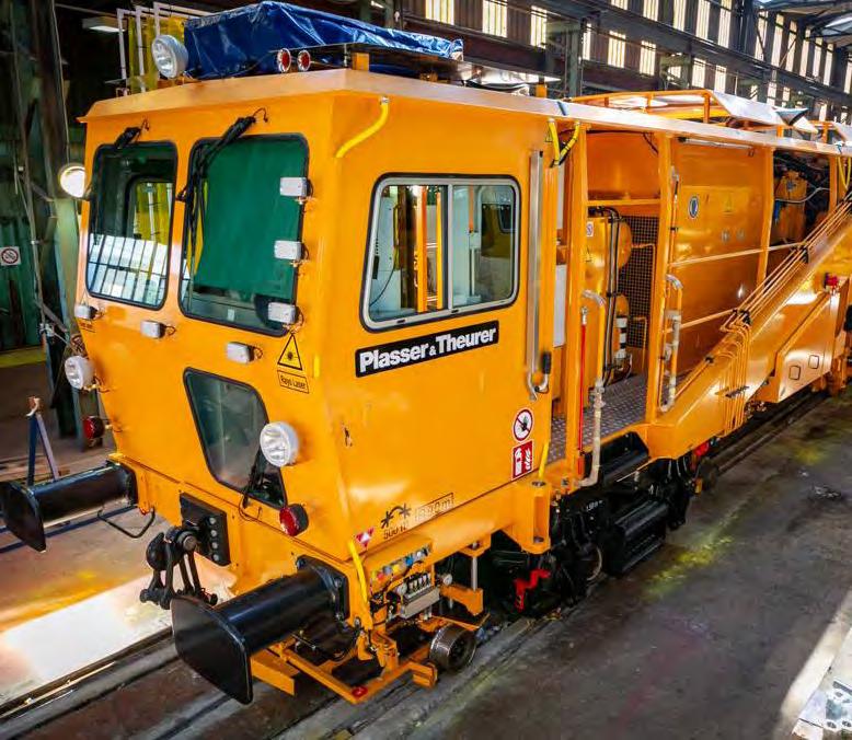
NEW EQUIPMENT INVESTMENT
Therefore more recently, TransNamib has invested 22MN$ (£2M) in a state of the art tamping machine to mechanically maintain the rehabilitated and newly constructed rail routes to a high standard. The machine manufactured by Plasser and Theurer (SA) is an 08-16SH (Split Head) tamper, capable of attending to both plain line and switches and crossings. The machine replaces the two former, probably much older Plasser machines. It represents the highest standard for compact tamping machines in split-head design and contains the same tamping and measuring technology as its larger counterpart high performance tamping machines, with top technology packed into a small machine frame. The 1067mm gauge, 3-axle basic structure with work units and measuring systems offers sufficient scope for individual equipment chosen from the Plasser modular systems and work units, for maintenance of both plain line and S&C units.
The new machine is equipped with four single sleeper tamping units fitted with 16 tamping tines which can be tilted laterally in pairs and also lifted and lowered independently of each other. These special features enable maintenance to be performed in the tightest areas of the turnouts. The lifting and lining unit is also adapted for these areas with both hook and roller clamp for lifting the track at various stages of the tamping process. Another innovation is that once placed in working mode, the roller clamps operate and open automatically, which enables higher outputs to be achieved, especially when tamping S&C units, allowing the operators to be more spatially-aware and fully focus on tamping position rather than constantly opening and closing clamps. The choice of a 16 tool single head machine allows for working on a variety of plain line sleeper spacings. The machine is fitted with the same measuring equipment as the high output tamping machines. The WIN-ALC automatic geometry guiding computer controls the machine during operations, in conjunction with the DAR (Data
Acquisition Recorder). (In fact the machine very much reminds me of my enjoyable times with the VolkerRail 08-90/4ZW machine and our 08-275NX on the Tyne and Wear Metro system.)
THE RECONSTRUCTION OF THE AUS - LUDERITZ RAILWAY
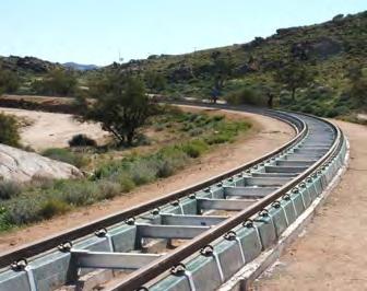
The original railway line to Lüderitz closely followed the Atlantic coast around Elizabeth Bay and Pelican Point with all its inherent consequences. Eventually consumed and corroded by the ocean, operations and maintenance were unsustainable, and the line closed. With an increase in Zinc export traffic through the port in recent years, the line was completely rebuilt, but this time across the desert and through the sand dunes. This called for a really innovative and different approach to permanent way engineering.
And now for something completely different! One of the track form systems used in Namibia, and fairly unique (in my experience) to South Africa, is known as T-Track. A tubular, modular track form construction.
TMT railway track is similar to a Mecanno set. Pre-manufactured, twin reinforced concrete beams linked with steel gauge (tie) bars provide continuous support for the rails. The twin beams and the layered formation on which they are laid, are designed as an integral system, and as such the track must only be laid on formations constructed strictly in accordance with that specific system design. The twin beams are tied together using specially designed galvanised steel tie bars, the ends of which encircle the beams and are thus not cast into the beams. This enables easy replacement of the tie bars, and also ensures that the tie bars do not work loose under repetitive dynamic forces. Tie bars are spaced at 3m intervals on straight track, and at lesser intervals on curved track to accommodate lateral forces. Intermediate rail fastenings are provided on stirrups which also encircle the beams. Rails are fixed to shoulders welded onto the tops of tie bars and intermediate straps by means of proprietary (Pandrol / Vossloh) fastenings. Resilience is imparted to the system by means of continuous resilient strip (rubber bonded cork) placed under the rails. The Transition zones at interfaces between Tubular Track and conventional ballasted track require special designs to accommodate the change in stiffness between the two systems. Further research and development into this permanent way system and potential improvements continues at the University of Pretoria in South Africa.
Diagram 1 outlines some of the potential construction savings by deployment of TMT in the appropriate conditions and context. • No ballast, no screening and no installation tamping is required • No sleepers are required, therefore no further maintenance tamping is required • With a continuous support and reduced rail stresses, reduced rail sizes can be used • Resilience is provided by a continuous pad under the rail, no pad creep • Fixed geometry, vertical and horizontal alignments remain constant • Integrated system, so formation layers form an integral part of the overall system • Reduced maintenance (i.e. moving parts) • Can be custom designed for any axle load or speed
TMT can potentially provide solutions in the following contexts:
• Desert conditions • Tunnels, platforms, yards and loading facilities (i.e. coal mines etc) • Turnouts • Low lying areas • Where earthwork costs need to be minimised • Simplicity of rapid construction
DESERT CONDITIONS
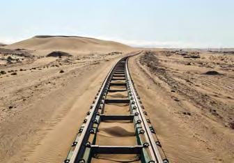
In the context of locations such as the deserts of Namibia, windblown sandstorms are frequent, variable and often significant (see following images). The deposited sand fills and contaminates the voids between the ballast in conventional track, thus removing the dynamics and the ability to maintain by such as mechanical tamping. The sleepers are not visible and the fines accelerate ballast and sleeper attrition under traffic. Rail corrugations appear and normal maintenance techniques are just not possible. In times of significant storms, conventional ballast is simply blown out of the track and across the desert.
Tubular Modular Track eliminates many of these maintenance problems and allows the railway administration to focus on the operational task of clearing sand deposits elsewhere. On occasion, these sand deposits can however be quite substantial, requiring several days of clearance activity. The subject of windblown sand on railways is quite a topic and much research has been undertaken, particularly as many administrations are now operating higher speed passenger services across arid desert areas (eg UAE, SAR, Iran). TMT is also currently on trial in Saudi Arabia.
Other solutions such as the elevated rail seat sleepers manufactured by CDG in Iran are now being trialled, both as sleepers and slabs on many routes. (I did challenge tamping tine penetration depths and pressures, especially for elevated sleepers and when transitioning from one sleeper type to another, but have not received any technical response to date.) In very general terms, windblown sand will reach the elevated railway or nearest rail and be deflected upwards. As its velocity decreases, it generally falls into the four foot. Once this begins, a cycle develops whereby the sand builds up and eventually engulfs the railway. Most solutions involve breaking this cycle.
By having an air gap beneath the rails from cess to cess, the windblown sand is no longer deflected upwards, but can pass right through the permanent way in significant quantities, without forcing out ballast or blocking the tracks. Alternatively, specialised lineside fencing can be deployed away from the track which slows down the velocity of the windblown sand and causes it to deposit away from the railway. These deposits can then be removed at leisure with no operational railway impact.
Therefore, Namibia has a requirement for two types of track construction, standard ballasted track in arid areas and Tubular Modular Track in the true sandy desert areas. Uniquely, this calls for differing maintenance strategies, skills and equipment.
In researching and preparing this paper, further contacts and more great friends have been made around the world which I never could have imagined. Therefore I am deeply indebted to the following and others for the assistance and supporting technical information given by: the Namibian Consulate in London, D&M Rail Construction Ltd, TransNamib Holdings, Plasser & Theurer SA, CBG (Iran) Ltd, T-Track Global Ltd, Independent photographers JonErik Munro (SA) and Laurie Mulrine (UK).
This article is aimed at widening understanding of our subject and perhaps inspiring some further research, particularly by our younger engineers and members. With that in mind, here are some research and study points that you may find useful for your CPD and NVQ portfolios, or even discussion at your section meeting!
1. What other types of modular track systems are available to engineers? 2. What are the risks of manually offloading concrete sleepers, and what alternative methods can be used?
3. What are the risks of manually offloading rails and what alternative methods can be used? 4. What is WinALC?
5. What equipment or systems are available to reduce windblown sand from railways? 6. What is the legislation covering the transportation of hazardous materials by rail?
Aberdeen to Inverurie redoubling inc Don Viaduct
ABSTRACT
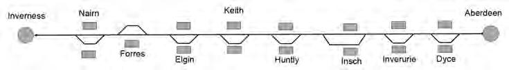
Aberdeen, population 200,000, is Scotland’s third largest city. Inverness is one of Europe’s fastest growing cities. Linking them is the Aberdeen to Inverness line, 107 miles of mostly single line railway with eight additional stations spread along the route, each with their own passing loop.
Until 2019 the line carried 11 trains from Aberdeen to Inverness per day and the same on the return, with the journey averaging two hours 18 minutes. An additional 15 commuter services ran between Aberdeen and Inverurie and two between Inverness and Elgin per day. The journey times and irregular service between Aberdeen and Inverness meant that the railway line did not offer an attractive alternative to road travel.
As part of a strategic review carried out by Transport Scotland in 2008 a set of key output requirements were established for the Aberdeen to Inverness line:
• hourly service between Aberdeen and
Inverness • half hourly service between Inverness and Elgin including a new station at Dalcross • half hourly service between Aberdeen and Inverurie including a new station at Kintore • a circa two hour end to end journey time • maintain, as a minimum, the ability to deliver existing freight access rights on the route.
Achieving these outputs would require a series of interventions to be carried out along the length of the route.
WESTERN INTERVENTIONS
Over the course of 2015, 2016 and 2017, interventions at Forres and Elgin on the western end of the route were designed and constructed. At completion the following works had been delivered:
• Elgin – extension of existing platforms. Extension of existing loop from 630 m to 1330 m including new F21.5 turnouts at either end allowing simultaneous arrival in to the station. Upgrade of Elgin LX (level crossing) to MCB-CCTV. Closure of Elgin signal box and removal of token exchange signalling system. New signalling system recontrolled to Inverness Signalling Centre. • Forres – new twin platform station with 1300m passing loop allowing simultaneous arrival in to the station. One new overbridge and one new underbridge installed. Two LX’s closed and two UWC’s upgraded. Closure of Forres signal box and removal of token exchange signalling system. New signalling system recontrolled to Inverness SC.
After completion of the works on the west, attention turned to the eastern end of the line. This section of line was the busiest on the whole route, allowing passengers to travel between Aberdeen, Dyce (Aberdeen airport) and the town of Inverurie. Due to a pressing need for increased commuter services at the eastern end of the line, emphasis had been placed on this section for the greatest extent of proposed redoubling. In addition a new station was proposed at the town of Kintore.
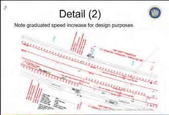
The existing line from Aberdeen to Inverurie was 16.25 miles of single line, with a 0.75 mile section of double track serving Dyce Station and Raiths Farm freight facility. The proposal to redouble this section of line was made more complicated because since the line was singled in the 1960s, the existing track had gradually been renewed and maintained to follow the racing line in six areas (see image 4), removing clearance issues through overbridges, platforms and a tunnel (see image 5).
In addition large sections of the existing single line had track components not suitable for a linespeed increase. This meant that a scheme to redouble 17 miles between Aberdeen and Inverurie, resulted in 60% of the existing line having to be renewed.
Over a period of 18 months, AECOM, Jacobs and Siemens designed the works required for the redoubling, with the output being:
• 40,000 m of new track including 15 new point ends • 85,000 m3 of earthworks • 4,300 m of retaining walls • 30 structures altered (extensions, infill, removal, strengthening) • 3 level crossing removals, 3 upgrades. • new station at Kintore • plus re-signalling throughout along with associated ancillary civils, resulting in the closure of signal boxes at Dyce and Inverurie AUTHOR
Robert McCafferty Technical Head of Track, BAM Nuttall
Robert started on the railway in December 1995, spending his first six years working with Scott Wilson Railways in Glasgow. The six years were spent in a survey and design environment and gave Robert the foundations for the years and roles to come. Six years followed with Mowlem Railways on the contractor side, followed by three and a half years with Network Rail.
Robert moved to Australia, spending two years in Brisbane with AECOM. Since returning in 2013, Robert has worked in various CRE and CEM roles and is now the Technical Head of Track for BAM Nuttall.
Robert is currently working towards CEng status through the PWI Experiential Learning Route.
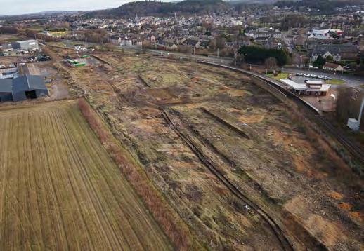
Image 2: Forres Station area - 2015.
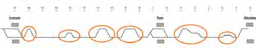
Image 4: Aberdeen to Inverurie redoubling - existing layout.
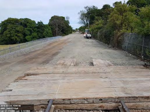
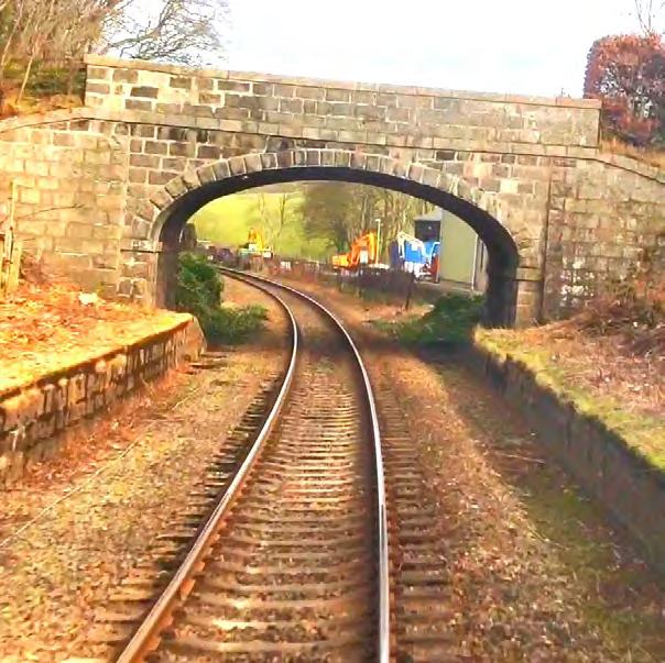
Image 6: View towards Aberdeen from 2 m 1715 yds. Image 3: Forres Station – December 2017.
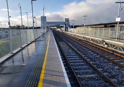
Image 5: Track centred through OB51 Blackburn Road.
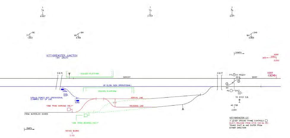

Image 8: Don Viaduct superstructure.
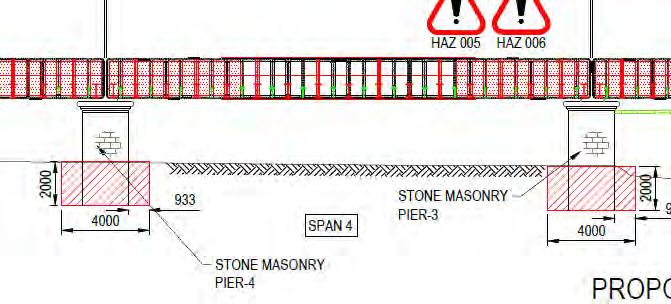
Image 10: Proposed substructure works - initial option. Image 9: Don Viaduct substructure.
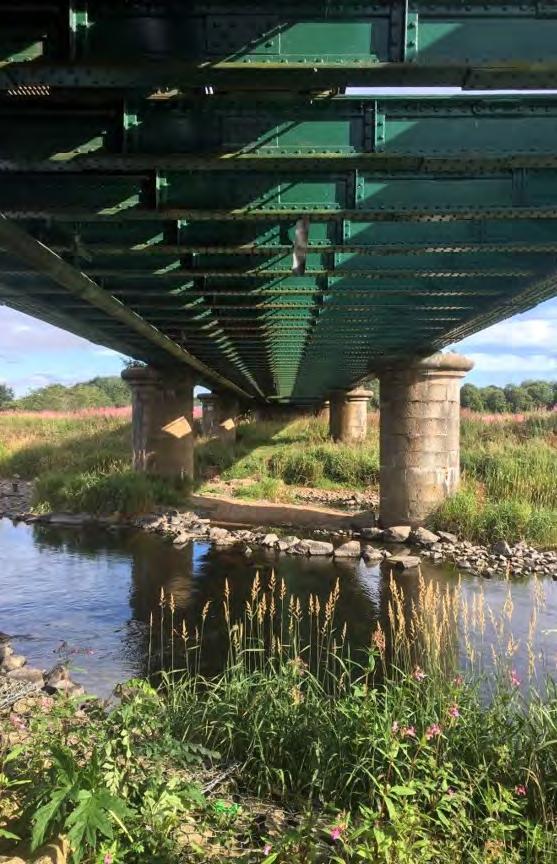
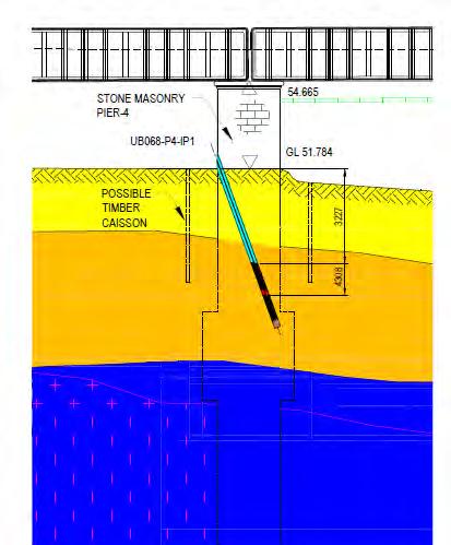
Image 11: Output from seismic ground penetration. These works would be carried out during a series of rules of the route possessions, weekend possessions (54 or 78hrs) and a 14 week blockade in each of the summers of 2018 and 2019.
2018 BLOCKADE - ABERDEEN TO DYCE
The 2018 blockade primarily consisted of works between Aberdeen and Dyce. During the 14 weeks, all earthworks, structures work, drainage, ancillary civils and trackworks were completed. During the initial part of the blockade, all the existing track was removed other than two short sections that only required tamping. This allowed the site to be managed as a high street environment, reducing the need for expensive rail mounted plant and allowing earthworks and drainage to be completed quicker (see image 6).
By the end of the blockade, the existing single line had been lifted, slued and renewed to form the down line. Four miles of the new up line had been laid, but not connected at either end and the Kittybrewster sidings area installed to a temporary alignment that maximised the amount of the new layout that could be installed, whilst still retaining the existing signalling and functionality. Image 7 below shows an extract from the Kittybrewster Scheme Plan at the end of the 2018 blockade. Black = existing, red = new track brought in to use, blue = new track not brought in to use.
2019 BLOCKADE - DON VIADUCT
As part of the 2019 blockade, Don Viaduct, a 103 m long, five span viaduct was to be upgraded to carry a second track. The viaduct carried the existing single track on waybeams over the river Don and its floodplain. The rail bearers span between cross girders supported from 2 outer main girders on a skew angle of 35 degrees. It was recently strengthened and repainted but only for single track loading. There is no deck, apart from an open mesh walkway. Therefore the deck is relatively lightweight (see image 8). The superstructure is supported by eight 2.1 m diameter granite masonry piers and two granite masonry abutments (see image 9).
DON VIADUCT - INITIAL OPTION WITH BALLASTED BRIDGE DECK
At early GRIP (Governance for Railway Investment Projects) stages it was established that the superstructure could be strengthened to support a second track. Several options including complete replacement and various strengthening schemes were considered. Key to this was removing the waybeams and installing ballasted track. The existing cross girders needed significant strengthening, so to simplify construction these would be removed and replaced with heavier sections. The main girders needed some straightforward strengthening, and a new steel deck, ballasted track and cantilevered walkway would be
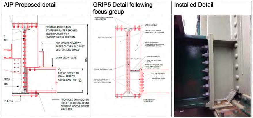
Image 13: History of cross girder detail.
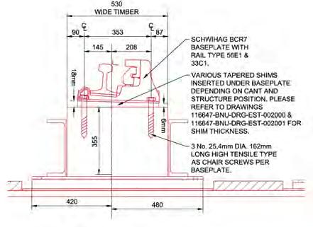
Image 14: Typical detail of waybeam and BRC7 baseplate.
installed.
Proposed superstructure solution:
• replace cross girders • 85 new cross girders / trimmers • 164 new stiffeners • strengthening of main girders • new cantilever walkway
In order to support the increased dead load of the deck, substructure strengthening would be required.
From ground investigation and record information available at the time, the piers were understood to be approximately 2 m deep. AECOM proposed installing a concrete collar around the base of the piers to strengthen the substructure (see image 10).
Following outline design some additional trial pits appeared to contradict the previous GI, and newly available record drawings seemed to show deeper foundations. This led to specialist survey by seismic ground penetration to confirm the depth of the piers and the depth of rockbed. This found that the piers were between 5-8 m deep (see image 11) which had a significant impact on the proposed solution. A collar around the base of the piers could not be installed without undermining the integrity of the structure and a collar around the pier at 2 m depth would not be effective as the load would still be transferred to the base of the pier. AECOM found that we would need to install the concrete collar with piles anchored into rock level for the design to work. This would have a significant impact:
• access to install piling would impede the installation of the scaffold needed to carry out steelwork strengthening • the piling and steelwork strengthening would all have to be carried out in the blockade. Not enough time was available to carry out the works • piling solution would be much more expensive
DON VIADUCT - REVISED OPTION WITH WAYBEAMS
Once these issues came to light a focus group was established involving BAM Nuttall, AECOM, Lanarkshire Welding and NR engineers. This was an open collaborative forum which met on a weekly basis to discuss the developing design. The aim was to integrate the requirements of design, construction and fabrication to develop a solution that met Network Rail’s requirements in terms of scope and programme.
The group looked at ways to avoid or reduce substructure strengthening. Finding a way to remove the need for piling in the river would go a long way to allowing the works to be delivered within the required timescales and budget. The group looked at ways of reducing the deadload by investigating a waybeam solution, removing the weight of ballast and steel deck plates. Using a risk-based assessment, AECOM compared historic loading against new loading to determine the reduction in factor of safety. If the factor of safety could be shown to be close to historic cases, the technical solution proposed could be shown to be feasible. For waybeams, AECOM calculated that the vertical loads only imposed a marginal reduction on the FOS (Factor of Safety). However, the longitudinal traction and braking loads meant that substructure strengthening was still required.
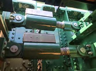
Piling in the river was still the key constraint to the programme so AECOM proposed the use of shock transmission units (see image 12). The shock transmission units lock up when longitudinal loading is applied transferring the load through the structure into new transition slabs behind the abutments. By doing this the longitudinal loading was taken out of the piers, and AECOM were able to demonstrate that the FOS were the same or better than the historic case. This solution took the piling out of the river clearing the way for the superstructure strengthening. The piles could be installed in advance of the blockade and the programme could be met. No substructure strengthening was needed on the piers.
By holding the focus group and including the fabricator in the design process we were able to simplify details and reduce the amount of time needed in the blockade and also improve the safety of the design. As an example, the standard detail was to attach the new cross girder to the main girder then install the u-frame stiffeners. All work that would need to be carried out during the blockade.
By amending the detail to install a stub end and stiffener in advance of the blockade using rules of the route possessions, a lot of preparation work could be carried out in advance. The blockade work then became a simple drop in and connect of the cross girder (see image 13). The focus group was a great benefit to the project, and a truly collaborative approach to resolving a key challenge on the project. Lessons learned will be applied to future
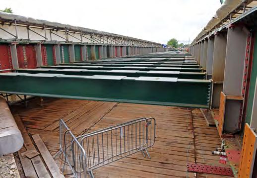
Image 15: Cross Girders from east side. Image 16: Waybeam troughs span 2.


Image 17: Track design - setting out - vertical. complex structure works.
DON VIADUCT - TRACK DESIGN
Having solved one problem, the focus group then had the challenge of developing details that allowed the waybeams to be installed effectively. The design of the waybeam was complicated by several factors:
• the structure was on a high skew • the track was rising at a gradient, and with differing levels of main girders • the design would need to include packer plates below the waybeams to ensure that the track sat at the correct level across the structure and also limit the variance in waybeam depth and size • the south end of the viaduct sat on a transition, with the cant varying from 49 mm to 0 mm. This required further packing plates to ensure the 1:20 rail inclination and crossfall were introduced in to the baseplate/waybeam system • a guard rail was needed as a mitigation to derailment loading as the design only proposed a light GRP deck. This dictated the type of baseplate used and required gathering panels on approach to the viaduct • finally, the civils element of the work (waybeams and below) had to be ready for the installation of the track to commence in week eight of the blockade. The track installation had a three week window before engineering trains had to cross to access renewal works to the west
On commencement of the detailed design, AECOM proposed the use of Schwihag BCR7 baseplate. The baseplate would be fitted with CEN56E1 running rail and 33C1 guard rails. These would be mounted on a variety of tapered shims and straight shims depending on the location (see image 14).
Once the components were agreed, AECOM then had to produce a Form B design that took all the factors above into account and provided enough information to allow the installer (Babcock Rail) to install the baseplates, shims and rails in accordance with the tolerances set out in Table A.1 of NR/L2/TRK/2102 Design and Construction of Track.
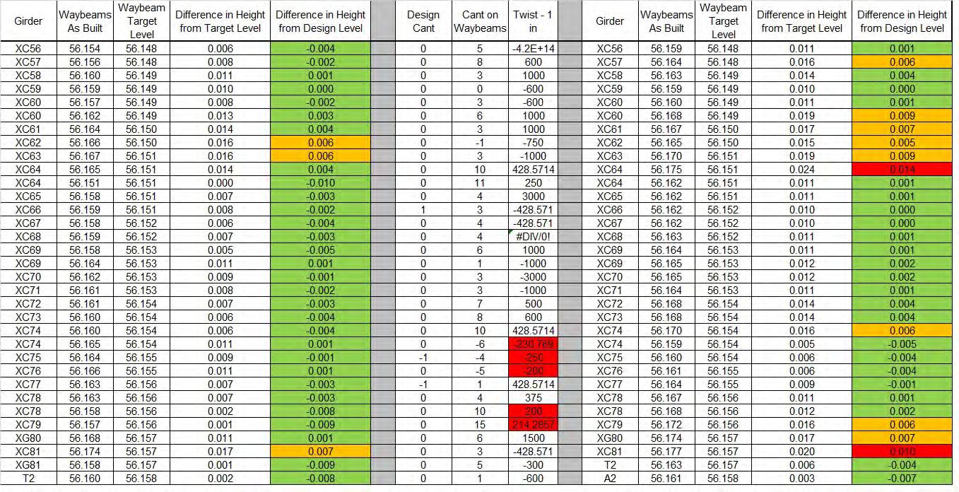
Image 19: Extract from waybeam as built survey.
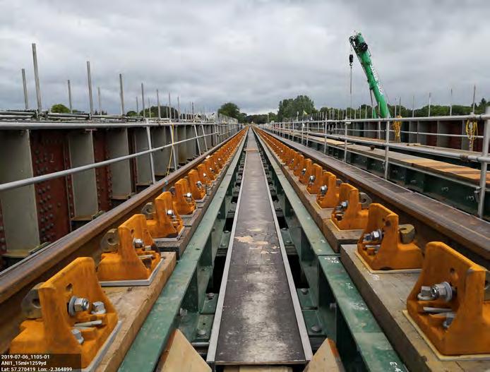
Image 20: Don Viaduct with planed waybeams on RH of picture.
TRACK DESIGN - VERTICAL
For a normal track renewal the design is built from a series of known values, rail level, rail type, sleeper type, ballast depth. From these an engineer can calculate what the design rail level, bottom ballast level and formation level are. In the case of Don Viaduct, it wasn’t quite so simple.
Rather than a formation level, we had to work up from the top of cross girder level (see image 15), this being an anticipated level rather than fixed, the anticipated part being explained by the following note on the drawing:
“The anticipated levels to the top of each of the cross girder fixing plates shown on this drawing are derived from the proposed depth of the new cross girder construction and the bottom flange levels for the existing main girders at each of the proposed new cross girder connections obtained from the pointcloud survey completed by Plowman Craven Ltd. in September 2018. These levels include an allowance for the estimated additional deflection of the main girders due to the increase in dead load following.”
The design then worked up from this point - anticipated level of cross girder fixing plate, anticipated depth of bottom packing plates, target level to underside of steel troughing fixing plate then the waybeam itself.
For the waybeams we needed circa 100 m3 of FSC Greenheart and FSC Ekki timbers, 350380 mm x 530 mm of D70 strength (as defined in BS EN 338). Due to these being non stock sizes, the timbers were either imported from a source country (Guyana, Gabon or Cameroon) or sawn from stock in Europe.
The supplier for the timbers, Gilmour & Aitken Timber Merchants, advised the tolerance of the timbers would be -0/+10 mm however with additional planning in Europe this could be
reduced to +/-1.5 mm. Adding more uncertainty to the steps needed to get from cross girder level to rail level. The output from the vertical element of the design is shown in image 17.
TRACK DESIGN - HORIZONTAL
As well as the factors noted above for the vertical alignment, the design and installation also had to take in to account the following requirements from NR-L2-TRK-3038 (longitudinal timbers) when positioning the baseplates:
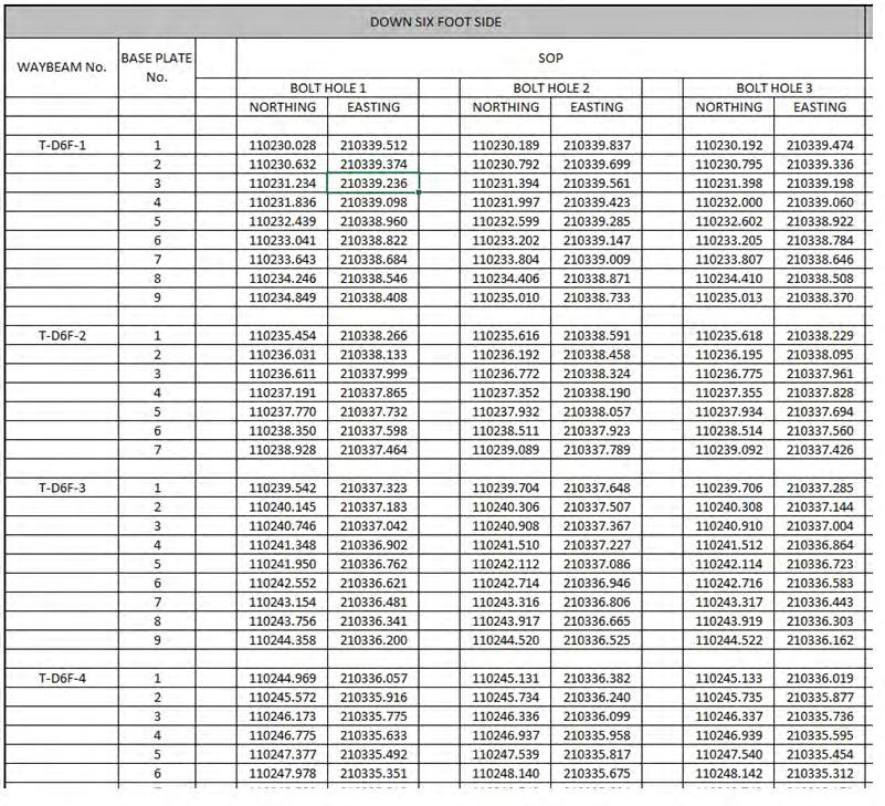
• baseplate centres (max 650 mm) • Centre of baseplate fixing hole to edge of waybeam (minimum 75 mm) • centre of baseplate fixing hole to end of waybeam (minimum 150mm) • max shim depth (30 mm) • baseplate rotation (+/-2 mm) • baseplate pair squareness (+/-5 mm) To enable the baseplates to be installed to the required accuracy, we asked that AECOM produce a table showing the co-ordinate for all three holes on every baseplate, a total of 2112 setting out points (see image 18).
TRACK DESIGN - MATERIALS
Once the design had sufficiently progressed we were able to order the PWay materials required for Don Viaduct, these consisted of:
• 800 BCR7 baseplates • 2 x gathering panel • 2 x run off panel • 28 x 18.288 m 33C1 guard rails with fishplates and screws • 800 straight packing plates in range of sizes from 10 mm to 2 mm • 220 tapered shims • plus AS screws, LS screws and other smalls required

Image 22: ITP for pairs of baseplates. The first eight weeks of the blockade passed without incident, eventually reaching the point where the waybeams were installed and ready for the track to be installed. Firstly an as built survey was completed of the top of waybeam level. As explained earlier, getting to this point required a build up from the cross girder, including packing plates and the inherent variability of the waybeam itself, so it was no surprise that in some areas the survey was slightly outside the required tolerance. As can be seen from image 19, the majority of the survey points were within the target tolerance (green), some were outside the target tolerance but still within 2102 tolerances (orange) and a small number were outside the allowable installation tolerance (red).
All the areas identified as being outside tolerance were high to design, so the solution proposed was to plane the affected areas of waybeam, reducing the height locally to the affected baseplates (see the RH side of image 20). Once the waybeams were within the required tolerance, the baseplates and tapered shims were laid out and a small piece of slave rail inserted to check the resultant rail level. The Babcock engineers were then able to calculate the depth of packing shim required.
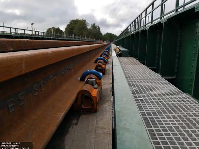
Babcock then installed 30 ft slave rails on the down line and clamped them up using temporary plates and clamps. The down line was then used as a service road to pull long welded rails across the viaduct for installation on the up line. This process required a series of rail rollers to be mounted on cross timbers supported by the waybeams. Once installed and clamped up, the process was reversed and the long welded rails installed on the down line. Once in place, the rails were clipped up and a final check carried out on the rail level, cant and twist. Height adjusting shims were then installed as required to ensure that the installation was in accordance with NR/L2/ TRK/3038, NR/L2/TRK/2102 and the AFC (Approved for Construction) design. The viaduct is 115 m long, so the rails extended beyond the bridge meaning no welds were required on the bridge.
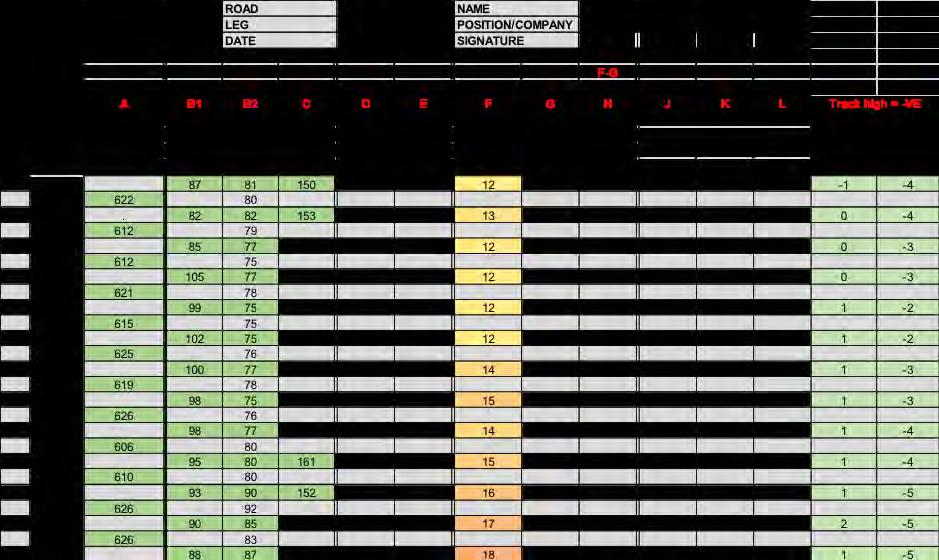
Given the bespoke nature of the installation it was necessary to create a bespoke inspection and test plan (ITP) to check and record that everything had been installed within tolerance. In image 21 you will see the ITP used to check the baseplates centres, offsets from the side and end of waybeams, depth of shims used, pilot hole depths and horizontal and vertical alignment. Image 22 shows the ITP used to record the relationship between pairs of baseplates – gauge, cant and baseplate pair squareness.
The works on the viaduct, both track and civils, were completed as per programme, meeting the reduced tolerances for horizontal and vertical alignment and with minimal snagging work required post blockade. Image 23 shows the track in its final arrangement.
2019 BLOCKADE – OTHER WORKS
As well as Don Viaduct, other major works were undertaken during the 2019 blockade. These included the closure of Pitmedden LX, upgrade of Boat of Kintore LX to MCB-OD, removal of three overbridges, upgrade of six underbridges, renewal of 8,000 m of existing track, installation of 15,000 m of new track and introduction of the new signalling system. The line opened for driver training on Saturday 17 August, with the first passenger trains running as planned on Monday 19 August.
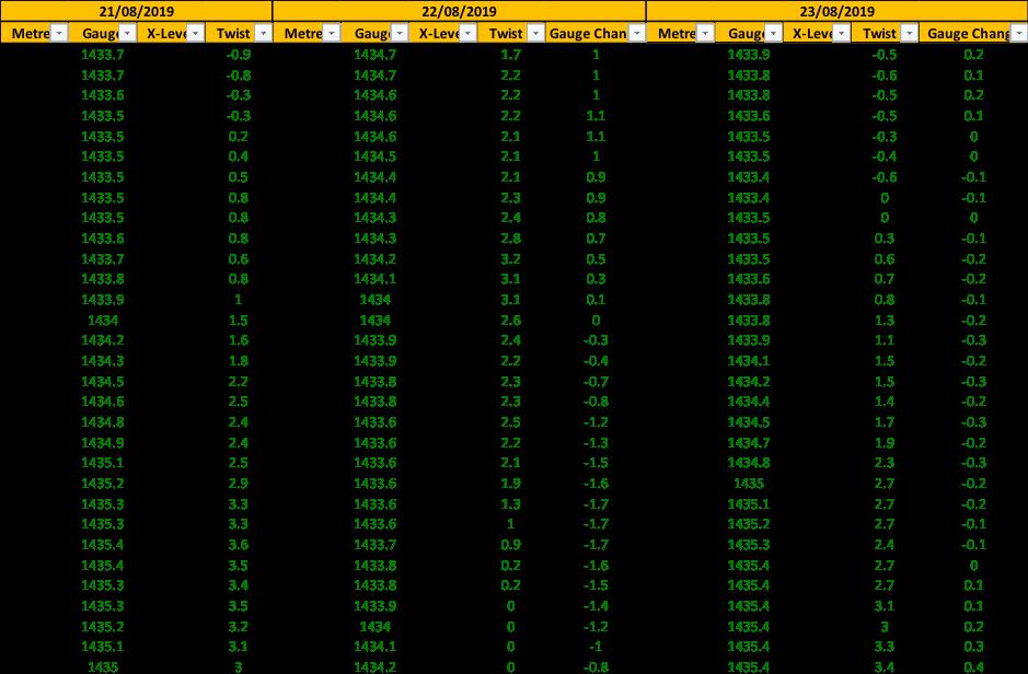
POST BLOCKADE MONITORING
At the end of the blockade we opened 11 miles of new track at the new linespeed of 75 mph with no requirement for a TSR. Due to the amount of earthworks, structures, drainage and new track installed, we agreed with Network Rail that an amber trolley would be run nightly for the first two weeks. Using two trolleys per night we surveyed 11 miles x 2 lines x 14 nights, a total of 308 miles of recording. No issues were detected in those two weeks or since. Image 24 below shows an extract of the spreadsheet used to compare runs over Don Viaduct.
A2I SUMMARY
Over the course of four years, BAM in partnership with Siemens, Babcock, AECOM and Jacobs designed and installed a series of upgrades at Forres, Elgin, Aberdeen to Inverurie and other locations on the Aberdeen to Inverness line. By the end the following works had been completed:
• 45,000 m of new track including 20 new point ends • 90,000 m3 of earthworks • 4,300 m of retaining walls • 33 Structures altered (extensions, infill, removal, strengthening) • four Level Crossing removals, six upgrades. • new station at Forres and Kintore • closure of four signal boxes • removal of token exchange signalling and recontrol to Inverness and Aberdeen SC.
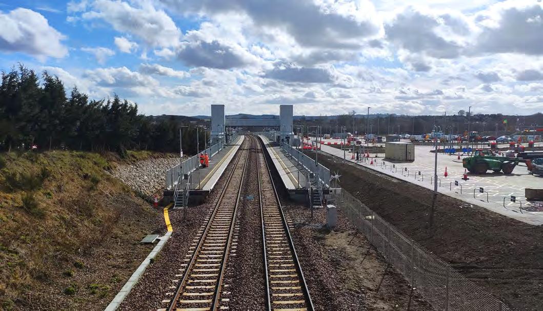
The journey from the 2008 Transport Scotland output requirements to now has taken 12 years, but isn’t yet finished. Further works are ongoing and planned on the Aberdeen to Inverness line. A new station is almost complete at Kintore (see image 25) and design has commenced for a new loop and station at Inverness Airport.
ACKNOWLEDGEMENTS
I’d like to thank David Herron, Associate Director with AECOM. David and I gave a presentation to the Winter Track Conference in December 2019 and his contribution to that forms part of this paper, particularly the Don Viaduct Civils elements.
REFERENCES
NR/L2/TRK/3038 - Longitudinal Timbers – Design, Installation and Maintenance NR/L2/TRK/2102 - Design and Construction of Track
Image 24: Comparison of amber trolley runs.
Low adhesion and sanders
INTRODUCTION
This paper will introduce the concept of low adhesion between train wheel and rail, including why it is so important to the railway, and will show how sand is used to improve low adhesion braking performance. Using sand is not a new concept, indeed steam trains were using sand for traction purposes over 100 years ago. However, by increasing sand delivery it is possible to deliver consistent train braking performance regardless of the underlying adhesion conditions. Solving the braking issue builds driver confidence in poor adhesion conditions and opens the door to using sand in traction to achieve higher performance.
This paper describes how the braking performance of different sanding configurations was quantified in a real railway environment, and how an innovative new analysis methodology was developed (since wheel/rail adhesion cannot be measured directly, the ‘Reference Adhesion’ provides a method of inferring effective adhesion during a brake event).
INTRODUCING LOW ADHESION
In order to accelerate or decelerate normally, railway vehicles rely on adhesion between steel wheels and rail. A typical ‘step 2’ service brake demand (representing a requested deceleration of 0.6m/s2 or 6%g) requires a coefficient of adhesion between wheel and rail of µ ≥ 0.06. Table 1 shows a range of typical braking demands, however please note that some trains have different brake rates and/or more granular control.
For the majority of the year, this level of wheel/ rail adhesion is readily available. However, each autumn, deciduous trees shed their leaves with some being crushed under the pressure of train wheels, bonding to the rail to produce a very hard and smooth layer. When combined with moisture, the resulting coefficient of adhesion between wheel and rail can be as low as µ = 0.01; six times lower than that required to sustain normal braking. During braking, if the demanded adhesion exceeds the available adhesion, the train wheels start to rotate more slowly than the actual train’s speed; the wheels are starting to slide. With a pneumatically actuated friction braking system, the Wheel Slide Protection (WSP) system will intervene to control the slide before any wheel damage occurs.
This is generally done on an axle-by-axle basis by rapidly venting pneumatic pressure in the brake cylinders, thus removing the braking force and allowing the wheel speed to increase back to true train speed. Some slide is beneficial as it can create heat, drying and scrubbing the track, improving adhesion for the following axles. This effect, known as wheelset conditioning, tends to work best at improving medium levels of adhesion - however it is less beneficial at very low adhesion levels.
WHY IS LOW ADHESION IMPORTANT TO THE RAILWAY?
Low adhesion can cause safety incidents (such as Signals Passed At Danger, or SPADs) and significant performance issues (such as station overruns or delays). In low adhesion, train drivers will naturally drive more cautiously; perhaps resulting in a lower maximum speed between stations and braking early and gently. There are also issues with traction, particularly affecting freight trains with limited motored axles. Each year, approximately 350,000 delay minutes are attributed to low adhesion. The direct impact of low adhesion is estimated to cost the GB railway industry and wider society £345m per year. The cost is made up of delay compensation, as well as the costs to mitigate low adhesion (including rail head cleaning) and the operational and reputational damage which occurs when train reliability and punctuality are degraded. Low adhesion issues are also a significant barrier to maximising future network capacity increases, since predictable and reliable braking is a key requirement for running trains closer together.
AVAILABLE MITIGATIONS
Although low adhesion exists mainly on the rail (the permanent way engineer’s domain), it primarily affects the rolling stock (the rolling stock engineer’s domain). There are several types of available mitigations against low adhesion:
• infrastructure-based mitigations include vegetation management (to reduce contaminant getting on to the rails in the first place) and rail head treatments (to clean the contaminant off the rails).
• rolling stock mitigations include sanders (the subject of this paper), as well as braking systems independent of wheel/rail adhesion (magnetic or eddy-current track brakes). There are also potential future technologies being evaluated, including using highpowered lasers or plasma arcs to burn contaminant off the rails, or using frozen carbon dioxide to freeze the leaf film and blow it clear of the track.
This paper focusses on enhancing the use of sanders. Since sanders already have a history of in service use on the railway, the technology is available now and the benefits are proven. Sand is also relatively inexpensive.
INTRODUCING SAND (AND SANDERS)
Sand, as shown in image 1, has been used on the railway for almost as long as railways have existed; historically steam locomotive drivers could open a valve to activate steam-powered sanders to aid traction. On a modern train, the WSP system controls the sander (automatic sanding) - although the driver often has a manual override button to obtain sand on-demand. AUTHORS
Andrew Lightoller is a Chartered Mechanical Engineer, working for DB ESG, a rolling stock consultancy. Andrew started his career in the rail industry as a graduate engineer at Bombardier where he took over as Brakes engineer on the Classic project. After various experience including a six month placement at Chiltern depot commissioning 168s and EU testing of aluminium foam, Andrew moved to Atkins as a Brakes & Pneumatics Engineer in 2001. In 2014, Andrew moved to DB ESG after their acquisition of WSPER and works as a Principal Mechanical Engineer involved with WSPER, brake testing and other general consultancy work.
Liam Purcell, CEng FICE FPWI
Liam is currently working as a Principal Consultant at Ricardo Rail, and leads the Intelligent Infrastructure team. Liam is a Chartered Civil Engineer and Fellow of the ICE and PWI, with sixteen years’ experience in the railway industry.
After initially joining AEA Technology Rail /DeltaRail as a graduate in 2003, he worked as a track consultant focussing on vehicle-track interaction and derailment investigation. Liam joined Lloyd’s Register Rail (now Ricardo Rail) in 2012 to specialise in wheel-rail adhesion, asset management and independent assurance of infrastructure projects.
Sanders deliver sand to both wheels of an axle either by having a pair of sanders (one for the left wheel and one for the right wheel) or by having two delivery hoses from a single sander. Since sanders are directional, Multiple Units are typically equipped with sanders at axle three in each direction.
When the WSP system detects wheel slide, it calls on the sander to eject sand. A typical sander configuration is shown in image 2; the sand is delivered from a hopper and compressed air carries it along a flexible sand delivery hose, ejecting the sand just ahead of the wheel. The sand is aimed at the wheel/ rail contact point, as shown in image 3. As the sand passes through the wheel/rail interface, the abrasive nature of the sand helps transmit the braking shear forces from the wheel into the rail, and the contamination layer is also damaged by the abrasive sand particles. The sand is crushed and turns to dust (see image 4); the dust probably helping to absorb moisture. Sanders are considered to have a two-fold benefit by:
• Providing a temporary boost to the level of adhesion experienced by the sanded axle (and subsequent axles to a lesser extent), and • Abrading or breaking down the leaf film, assisting in its removal.
It should be noted that automatic sanders do not predict where to lay sand: they need wheel slide to occur first to trigger the sand delivery. Automatic sanders were initially introduced on multiple units by British Rail Research, starting around 1996. Most modern multiple units are equipped with fixed rate sanding ahead of the third axle, delivering a nominal 2 kg of sand per minute (to each wheel). The sander is often inhibited at speeds below 10mph, to avoid laying a high density of sand which could cause interference with track circuits. (2 kg / min of sand, deposited at 10 mph, is equivalent to a sand density on the track of 7.5 g/m. At this density, sand is unlikely to interfere with track circuits.) The above configuration, herein referred to as Single Fixed Rate Sanding (SFRS) undoubtedly has low adhesion braking performance benefits. However, by using more sand, there is potential to deliver greater benefits.
DELIVERING MORE SAND
A greater quantity of sand could be delivered through:
• Distributed sanding (multiple sanders distributed along the train), and • Variable rate sanding (speed-dependant sand discharge rate, with higher sand rates at higher speed).
The key benefit of the variable rate sander is that it can deliver a higher rate of sand at higher speeds (4 kg / min at speeds above 20 mph), yet it is able to vary its flow rate at lower speeds to respect the 7.5 g/m guidance. A comparison of sand flow rates for fixed and variable rate sanders is given in image 5. A train equipped with variable rate sanders at axle 3 is referred to as Single Variable Rate Sanding (SVRS), and when two axles are equipped (typically axles 3 & 7) it is known as Double Variable Rate Sanding (DVRS).
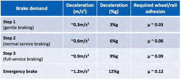
Table 1: Relationship between brake demand and adhesion. Image 1: Railway sand (note coarse grains).
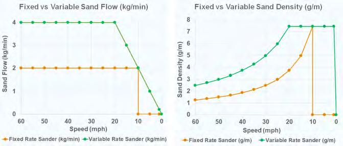
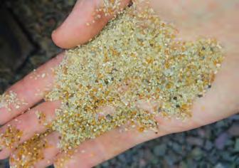
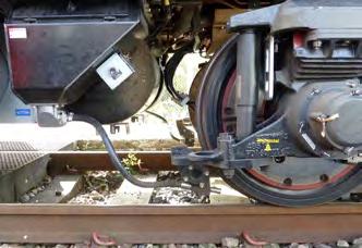
Image 2: Typical sander configuration (note sand hopper and flexible delivery hose).
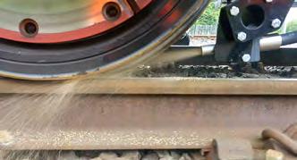
Image 3: Sand being ejected from the sand delivery hose, directed at the wheel/rail interface (train is stationary; test button used to eject sand for photograph).
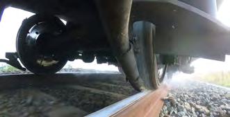
Image 4: Sand being delivered at speed (≈ 40 mph) during wheel slide.


Image 7: Paper tape being laid at the test site.
The T1107 project aimed to determine the benefits of enhanced sanding that could be achieved in low adhesion conditions, using a real train running on real track. The test objectives were:
• quantify the benefit of distributed sanding; • quantify the benefit of variable rate sanding; • determine if it is possible to deliver ‘assured’ 6%g braking in low adhesion conditions.
TEST SITE
Testing was carried out at Network Rail’s RIDC (Rail Innovation and Development Centre) Melton facility; the line used for testing was approximately 7 km in length - an aerial view of the test site is shown in image 6. The site was divided into a 2 km acceleration zone (for accelerating to 55 mph); a 1 km low adhesion zone (to undertake the sander testing) and a 4 km run-off zone (for train deceleration and a safety buffer).
To create the low adhesion zone, 1 km of track was ‘contaminated’ with paper tape. The tape is typically used in the packaging industry and is derived from tree pulp and is therefore a similar composition to real leaves. This artificial (but representative) low-adhesion zone enables consistent and reasonably repeatable tests. A bespoke trolley was used to lay the paper tape (which is gummed on one side, so it adheres to the railhead), as shown in image 7.
TEST TRAIN
Two brand new four-car Class 387 EMUs were used for the testing, and were modified by:
• provision of variable rate sanders in advance of axles 3, 7, 11 and 19; • installation of water spray system ahead of axle 1 (to moisten the paper tape to create low adhesion); • installation of transducers to measure and record parameters including axle speeds, brake cylinder pressures, train speed, etc.
SANDER TESTING METHODOLOGY
The paper tape was ‘bedded’ by coasting over it and then ‘conditioned’ by undertaking full-service brake applications while using the water spray to moisten the tape. Once sufficient slide was apparent, an un-sanded test was undertaken to verify that a suitable low adhesion layer had successfully been created. Finally, a sanded braking test was undertaken, and the resulting data analysed to determine basic statistics of the test.
Initially, the test methodology was based on quantifying the low adhesion train braking performance without sand (the control test) followed by a sanded test; with the control test effectively providing a benchmark from which to compare the improved deceleration of the sanded test. A working assumption in this was that adhesion would remain constant between individual tests. In reality this was not experienced. After the first few testing sessions, it became clear that the changing environmental and rail conditions produced substantial adhesion changes between consecutive tests, and the planned test strategy was not appropriate. A new approach was needed.
REFERENCE ADHESION
A new strategy, Initial Reference Adhesion, was devised whereby the first two (un-sanded) axles of the train were used to estimate the initial underlying wheel/rail adhesion that the train was running over. This novel approach to inferring real-time adhesion was a significant breakthrough for the project because not only did it provide a suitable method of comparing one test with another, but it also removed the need to establish identical rail conditions between tests.
This new approach relies on the assumption that the WSP system regulates the brake force (in this case brake cylinder pressures) to maximise the use of the available adhesion to stop the train in the shortest distance. As a result of this assumption, differences in WSP system performance may lead to small differences in the results but comparison of stops from the same train (and possibly of different trains using the same WSP system) should be directly comparable.
Reference Adhesion is an approximation of the wheel/rail adhesion that each axle of the train was able to utilise over the course of the brake application. Initial Reference Adhesion is the average Reference Adhesion for the first two axles of the train, and provides a snapshot of the incoming track condition, before it is changed significantly by the train.
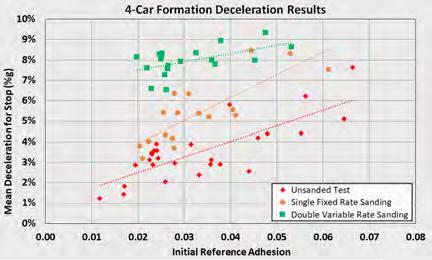
Image 8: Mean deceleration achieved for DVRS, SFRS and un-sanded stops. Image 9: Stopping distance achieved for DVRS, SFRS and un-sanded. stops.
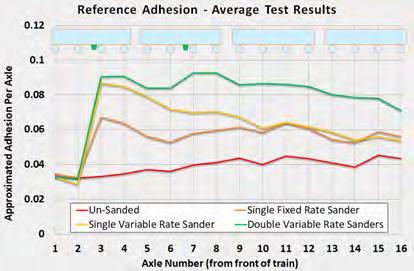
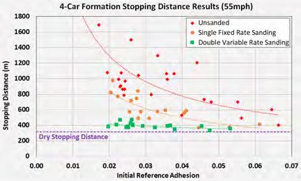
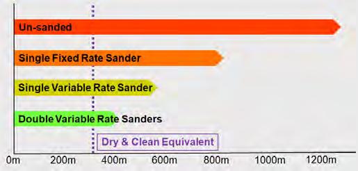
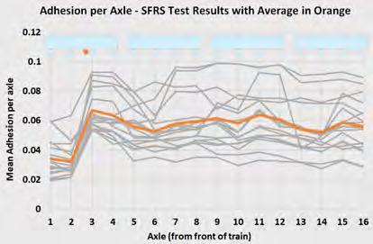
Image 12: Reference Adhesion plots for axles along the train, each grey line indicates an SFRS test run and the orange line shows the mean SFRS.
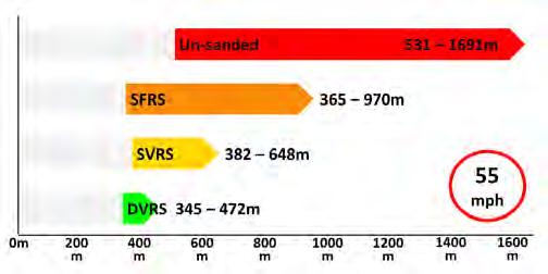
Image 14: Range of stopping distance results from 55 mph for differing sander configurations (Initial Reference Adhesion between 0.02 and 0.045). Image 13: Reference Adhesion plots for axles along the train, each grey line indicates a DVRS test run and the green line shows the mean DVRS result.
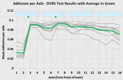

Image 15: Examples of theoretical maximum sand density of 7.5 g/m, if all the sand were to land on the railhead in a narrow bead (left) or more spread out (right).
Equation1.
Calculation of the Reference Adhesion of an axle is relatively simple, as indicated above - (equation 1) where,
• ‘Average BCP’ is the mean Brake Cylinder Pressure measured over the brake application for that axle; • ‘Dry Rail BCP for Brake Demand and Load’ is the BCP pressure in good (nonslide) adhesion conditions after automatic adjustment for passenger loading; and • ‘Dry Rail Deceleration for Brake Demand’ is the straight & level track retardation rate in ‘g’ for the selected brake demand.
The above calculation assumes that the automatic adjustment of brake cylinder pressures for passenger load assures a similar retardation rate independent of vehicle payload - otherwise the deceleration rate should also be factored for load.
The Reference Adhesion for each axle provides a method of demonstrating how adhesion changes on an axle-by-axle basis along the train. The Initial Reference Adhesion (average of first two axles), provides a benchmark of the starting adhesion conditions and enables comparison of one test with another.
RESULTS
The T1107 testing project carried out 147 sanded tests and 78 un-sanded tests. The Initial Reference Adhesion methodology provided an understanding of the adhesion levels at each axle and allowed:
• a comparison of achieved deceleration and stopping distances against Initial Reference Adhesion for un-sanded and sanded stops; • a comparison of adhesion levels axle-byaxle along a train; and • a demonstration of the benefits of enhanced sanding.
DECELERATION & STOPPING DISTANCE
Image 8 demonstrates the effectiveness of DVRS (green squares) over SFRS (orange circles) and un-sanded stops (red diamonds). The smaller amounts of sand from existing sanders (SFRS) may be seen to be reasonably effective at medium adhesion levels (Initial Reference Adhesion >0.05) but its effect is limited and more variable at lower adhesion levels. Increasing the sand output to that of DVRS provides a significant benefit at the very low adhesion levels approaching 0.02. In terms of stopping distance, the vertical axis of the graph can be changed to distance and instantly it can be seen that in very low adhesion, DVRS returns stopping distances that are approaching those of dry rail (image 9).
ADHESION IMPROVEMENTS ALONG THE TRAIN
Looking at the calculated Reference Adhesion along the train enables an understanding as to how the improvement in stopping distance (or deceleration) is being achieved. Image 10 shows the average of all the tests for each sander configuration tested. The red line indicates the average un-sanded adhesion improvement along the train resulting from wheelset conditioning only. The other three results demonstrate the improvement from the existing SFRS (orange) to SVRS (yellow) and finally to DVRS (green). It is the significant improvement in adhesion for all of the axles that creates the significant additional braking force of DVRS and thus reduced stopping distances.
DVRS BENEFITS
From the above results we can see that the stopping distances with DVRS are significantly reduced when compared to un-sanded and existing SFRS stops. The trendlines shown in image 9 can be used to estimate an average stopping distance for any given Initial Reference Adhesion; image 11 shows stopping distances from 55 mph at adhesion = 0.02.
As well as the significant improvement in average stopping distance, enhanced sanding delivers much more consistency in the stopping distance. The variance in Reference Adhesion along the train and between tests may be
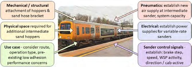
Image 16: Things to consider when retrofitting DVRS.
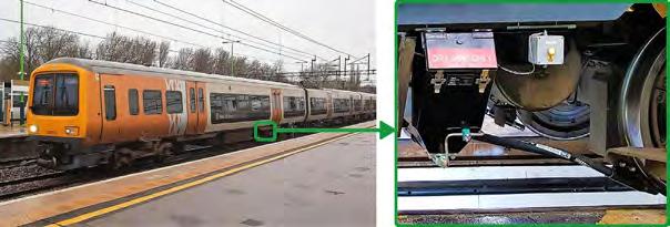
Image 17: DVRS retrofitted on Class 323.
seen with the existing SFRS results (image 12) and the greater consistency of DVRS results (image 13). The variation in stopping distance can be simplified into another graph; image 14 illustrates the shortest and longest stopping distance for each sander configuration. This further demonstrates the benefits of the additional sand that DVRS brings.
AND AN ‘ASSURED’ 6%g?
The final objective was to determine if it is possible to deliver ‘assured’ 6%g braking in low adhesion conditions (since train timetables are typically designed around 6%g deceleration). The Class 387 brake step 3 results with DVRS, plotted as deceleration (vertical axis) in image 8 show that for every test undertaken, the mean deceleration was greater than 6%g. This result is important for maximising future network capacity, since predictable and reliable braking (regardless of underlying adhesion conditions) is a key requirement to enable future train control systems to run trains closer together.
INFRASTRUCTURE CONSIDERATIONS
To reassure the permanent way engineer, sanders only dispense sand during wheel slide events. By this definition, sand is only deposited where low adhesion is present on the track and is causing the wheels to slip. Sanders are designed to discharge a maximum 7.5 g of sand per meter of rail – as seen in image 15. At 60 mph the sand density will be three times lower than this, at just 2.25 g/m (refer back to image 5). The enhanced sanders will help to clean the track, which should improve the track conditions for the following train; this ought to lead to fewer instances of slide and wheel flats which are known to damage the track. The authors are not aware of any evidence that enhanced sanding leads to any higher wear rate of the rail, nor that it will lead to sand-contamination of the ballast. However, if turnouts are located in braking areas, there is a chance that enhanced sanding could lead to a slightly higher wear rate of switch slide bearing surfaces.
IN-SERVICE PILOT
Following the T1107 testing, train operators were interested in realising the potential benefits of DVRS to improve autumn performance; however, the challenges of retrofitting were not clear. To support industry adoption of DVRS, RSSB commissioned a project to implement an in-service pilot of DVRS on the mainline railway. This project aimed to provide dedicated support for the first in service retrofit of DVRS and to verify that the benefits of DVRS demonstrated on the test track would translate into similar benefits for normal in-service running of a passenger train. In early 2018, several train fleets were identified as candidates for the in-service pilot. A feasibility study was conducted for each and it was considered feasible to retrofit DVRS to all the fleets. However, all had some technical challenges to overcome; image 16 shows the main considerations. Equipping a unit with DVRS typically requires upgrading the existing fixed rate sander at axle three to a variable rate sander, and adding an additional variable rate sander at an intermediate axle (typically axle seven or eleven depending on unit formation and available space). West Midlands Trains Class 323 units were selected for the in-service pilot and were equipped with DVRS (image 17); these were introduced into passenger service on the Cross-City Line in Birmingham in 2019. The trial units were also fitted with remote condition monitoring, to capture key performance data.
DRIVER FEEDBACK
Following the introduction of DVRS equipped units, a series of low adhesion driver familiarisation sessions were conducted in order to provide an opportunity for train drivers / representatives to familiarise themselves with the enhanced low adhesion braking performance afforded by the DVRS equipment. During conversations with the drivers, they were impressed with the performance that the DVRS system gave them. Driver feedback included “anything that stops me a metre quicker, I’m happy with” and “this DVRS system is brilliant, absolutely brilliant, a marked improvement in stopping”. In addition, both WMT’s Operations Director and Network Rail’s Head of West Midlands Operations were very happy with the performance, describing the new way of using sand as a “game changer” and “ground-breaking”.
Enhanced sanding is the simplest technical solution to low adhesion, but the human factors aspect must not be overlooked. It will take time for drivers to become accustomed to the enhanced braking that sanding provides and to gain confidence to let the train deal with low adhesion conditions. A train driver’s primary concern is the safety of the train and its passengers; changing driving style sufficiently to make use of the extra sand will take time.
CONCLUSION
The standard which controls the use of sanders on multiple units is GMRT2461 ‘Sanding Equipment’. This standard was updated in 2018 to include the results of the T1107 testing work, to encourage the GB rail industry to adopt distributed and variable rate sanding. The work described in this paper represents a significant advancement in the understanding of enhanced sanding. The work has quantified the benefit of different sanding configurations, and has shown how fitting DVRS on a modern four car unit can consistently deliver 6%g braking irrespective of underlying adhesion conditions. The work has also shown how it is feasible to retrofit DVRS to existing multiple units and has provided guidance for those doing so. The general trend is that, as the sand is increased, the stopping distances get shorter but (possibly more importantly) the variation in stopping distances is reduced, indicating a greater predictability and consistency for the train driver. DVRS also has the capability to unlock future network capacity by enabling control systems to run trains closer together.
ACKNOWLEDGEMENTS
With thanks to our client Rail Safety and Standards Board (RSSB) for developing, managing and funding the programme of low adhesion work. Thanks to project partners, Great Western Railway, Porterbrook, Network Rail, Freightliner, Serco Rail Technical Services, Knorr Bremse, Bombardier, Bridgeway, West Midlands Trains, AB Hoses and Instrumentel.
BIBLIOGRAPHY
T1107 ‘Trial of Sander Configurations and Sand Laying Rates’ IMP-T1107 ‘Class 323 DVRS In-Service Pilot Issue’ COF-BRP ‘Class 323 DVRS Driver Familiarisation’ All reports are available through RSSB’s repository, www.sparkrail.org
Iranian National Railways (RAI)
OVERVIEW
The Islamic Republic of Iran is a country in South-West Asia with a territory of 1,648,195 km2 and approximately 83 million of population, with a median age 32. It is the 19th most populated country in the world. Iran is a mountainous country with approximately 30% or 34 million hectares of desert territory. Communities are located in areas where there is water and cities are separated by hundreds of kilometres. The density of population in Iran is 51 persons per km2, which is low, compared to UK with 270.7 person per km2. Iran shares its land border with seven countries: Armenia, Azerbaijan, Turkmenistan, Afghanistan, Pakistan, Iraq and Turkey. Three of them are former USSR countries: Armenia, Azerbaijan and Turkmenistan.
RAILWAY SYSTEM IN IRAN
The railway system in Iran is state owned, controlled by the Ministry of Roads and Urban Development. The centre of the railway network is Tehran, which is the capital of Iran and is connected to 19 local regions. One of the outstanding engineering achievements of Iran was a construction of the Trans-Iranian Railway. Construction began in 1927 and was completed in 1938. It is a 1,394 km line with 90 stations along the route. The railway line stretches from the Caspian Sea through the central part of Iran to the border with Iraq. The railway runs along the highlands and reaches 2,000 m above sea level, passing over 3,000 bridges and through 126 tunnels in the Zagros Mountains. This railway played an important role in the Second World War as a route delivering supplies to the Soviet Union. The railways in Iran use standard gauge, electrified at 25 kV 50 Hz AC, which is the same as Turkey and Iraq. The majority of the railway lines are constructed with UIC60 rails on B70 concrete sleepers. Most of the Iranian railway network is a single track, which is approximately 82%, and 18% is double track. A large part of the railway network passes through desert. In these areas, windblown sand on the track reduces the elasticity of the track bed. This leads to degradation of the railway track and rolling stock and increases their vulnerability. It affects reliability, safety and passenger comfort. Maintenance of these lines take lots of effort and puts huge financial pressure on Islamic Republic of Iran Railways (RAI). RAI found that one of the most economically efficient and best long-term solutions for windblown sand mitigation is planting vegetation (Zakeri, 2012).
The RAI network includes 360 stations and 12,998 km of line. It is an approximately 7.89 km railway line per 1,000 km2 of land. In the UK, this figure is almost ten times higher and reaches 66.7 km of railway line per 1,000 km2 of land. On the 1 January 2020, the Iranian Transportation Minister announced that in the next two years the railway network in Iran will be expanded by another 1,500 km and will reach 25,000 km by 2025. There is a total of 45 projects to build new lines and 140 projects to upgrade existing lines (Seyedvakili et al., 2019). Image 2 shows the cost share of Iranian railway projects.
The Iranian railways are working on a demandbased principle. For freight trains, there is no fixed timetable. Railway responds to demand and runs trains when there is enough freight to transport. This causes long delays in the delivery of freight to their destinations. Iranian railway network has 170 terminals with 200 origin to destination demands, which handle around 1,500 wagons every day (Yaghini et al.,2013). In 2006, RAI had 50 depots, 565 locomotives, 16,330 wagons and 1192 passenger coaches (Mirabadi and Sharifian, 2010). Nowadays, lots of rolling stock is manufactured domestically. In 2019, there were 432 new freight wagons, locomotives and passenger coaches commissioned into service. The railway system of Iran is continuously
Inara Watson
PhD Researcher PWI member London South Bank University
Inara was born in Latvia and graduated with a BSc in Mechanical Engineering from Riga Technical University. She has a MSc in Transport Engineering and Planning from London South Bank University and is in her last year studying at London South Bank University for a PhD.
Her research interests are focused on railway engineering and sustainability. Inara is currently involved in two international projects in Australia and Ecuador. Inara is a member of the PWI, ICE, OR and the DMDU society.

AUTHOR
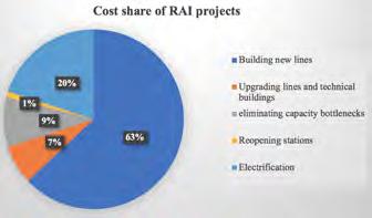
Image 2: Cost share of RAI projects (data taken from Seyedvakili et al., 2019). expanding. Construction of railway lines increased from 120 km per year in 2013 to 180 km in 2017. There are 6,500 km of railway lines under construction. Also, there are several projects for electrification and upgrading existing lines. One of them is the 926 km double track Tehran-Mashhad, the busiest railway line in Iran. The line will be electrified, which will increase the speed of trains from 160 km/h to 200 km/h. It will reduce the travel time by almost half and increase the capacity of the line. Electrification of the line will increase traffic on the route from 17 to 40 trains per day in each direction, which permits an increase of the ridership from 2.7 million to 33 million and freight from 1.5 to 10 million tonnes per year by 2032. The total cost of the project will be around $6bn. This project is partially financed through Chinese loans.
Iran has an ambitious plan to construct one of the largest HSR networks in the Middle East. Iran has 1,336 km of HSR under construction, 177 km planned and 165 km long-term planning with an operational speed of 250 km (Uic.org, 2020). Construction of 410 km HSR Tehran-Isfahan, with operational speed up to 300 km/h is being carried out by the China Railway Engineering Corporation (CRECP). Also, it involves Germany’s Siemens, Italian group Ferrovie dello Stato and Khatam Al-Anbia Construction, owned by Iran’s Revolutionary Guard (Globalconstructionreview.com, 2020). The cost of the project is estimated to be $41.8bn and completion is set for 2021. In 2015, the French consultant Arep signed an $8m deal to redevelop the three largest stations in Iran: Tehran, Qom and Mashhad. It is part of a seven-year programme for upgrading railway infrastructure for which the total cost is $25bn (Rogers, 2015). Qom-Arak HSR line 135 km long and Tehran-Hamadan line 320 km will be built by Italian Ferrovie dello Stato company as part of a €5bn credit promised by Italy (Globalconstructionreview.com, 2020). The use of railway capacity in Iran is heterogeneous. Capacity of most railway lines in Iran is used by no more than 25%, only routes from Andimeshk to Qom, Isfahan to Bafgh and a couple of others where capacity of lines is used Table 1: Major stations in Iran.
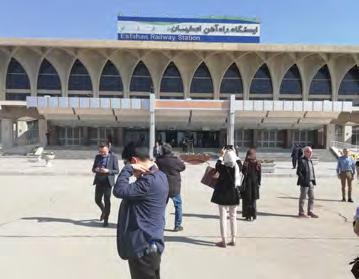
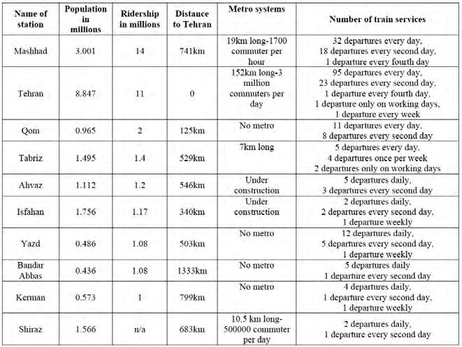
up to 75% (Seyedvakili et al., 2019). The major reason to build HSR is to increase the capacity of railways. This involves a large financial and carbon investment. Before a decision is taken to construct HSR, there is a need to look for other solutions to improve the capacity of lines, such as upgrading existing infrastructure, implementing an advanced signalling system and upgrading rolling stock. However, some countries when deciding to construct HSR put other reasons first, such as a defence or to affirm the regional leader status or promoting the image of the country (Watson et al., 2019). To build Iranian HSR it will need to have a large financial input and use a large amount of natural resources. Due to the low capacity of existing railways a new HSR will not give sufficient carbon savings.
IMPROVING THE LINKS TO NEIGHBOURING COUNTRIES
Iran is located between Europe and Asia and the Iranian network has nine major corridors which cross the country from North to South and from West to East. Iran has 13 rail borders, ten of them in operation and three under construction. Lately, Iran has increased cooperation with Turkish and Pakistan railways, also with parts of the former USSR. Iranian railways have bogie-changing stations on the border with Azerbaijan-Jolfa station and on the border with TurkmenistanSarakhs station. Azerbaijan and Turkmenistan have 1520 mm gauge. Iranian railways have bogie-changing stations on the border with Pakistan, as Pakistan has 1676 mm gauge. One of the bogie-changing stations is the Zahedan station, which has been in operation since 2007. Iran and Pakistan are working on projects to increase the volume of freight transported by railway and the number of tourists and pilgrims from Pakistan to Iran and Iraq travelling by railway. There is a strong will from Iran and Pakistan to restore the Islamabad-Tehran-Istanbul railway network. Russia is very heavily involved in construction and modernization of Iranian railways. One of the joint projects was the construction of a new 160 km railway line Astara-Astara between Republic of Azerbaijan and Iran. The main feature of the project was to build a railway with a dual gauge 1520 mm and 1435 mm. This line is part of the International North-South Transport Corridor (INSTC) that connects Russia, Iran and India. The 7,200 km long corridor includes different transportation modes, such as shipping, rail and road. Studies have been made for a third railway link between Iran and Azerbaijan and further to Russia, the Ardabil-Parsabad railway. Another large joint project of the Russian and Iranian governments is to electrify 495 km of the Gsarmsar-Ince Burun line near the border with Turkmenistan, with the estimated cost of $1.3bn and construction taking 4-5 years. (Rogers, 2015) This will allow an increase in speed and as a result will increase the capacity of the line to ten million tons per year. Russia and Iran have a long history of technical and military cooperation.
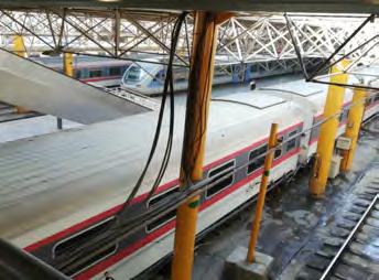
Iran is developing a railway that will connect the Iranian city of Khaf in Eastern Iran to the Afghan city of Herat. In the past, the Afghan government did not encourage the construction of railways for strategic reasons. Iran is enhancing communication and influence on neighbouring countries. The Iranian government has an international project to connect Iran, Iraq and Syria by railway. This will link the railway networks from the Persian Gulf to the Mediterranean Sea. The first step of this project will be the construction of a 32
km link between Shalamcheh city in SouthWest Iran to Basra city in Southern Iraq. All these projects show that the volume of freight and the number of passengers transported by railways in Iran is increasing. The volume of freight transported by Iranian railways in the last year increased by 140% compared to the previous year and reached 31 million tons. The railway’s share in freight transit increased to 14%. Passenger numbers reached 42 million in 2018.
STATIONS
RAI has a vision to transform railway stations into transportation hubs. To do this is a need to enhance many transport options in one place where passengers and freight exchange between different transportation modes. Tehran, with one of the busiest metro systems in the Middle East, or Mashhad, where there is a light rail system, will be good options for a transportation hub, but for other cities, such as Isfahan, it looks unlikely. Many railway stations can only be reached by private car or taxi. Isfahan railway station is located 15 km distance from the centre of the town in the desert and is surrounded by a few buildings. The railway station cannot be reached by public transport, only by private car or taxi. It is a two-storey huge building but most of the time it is deserted, as it has only a few weekly departures for passenger trains. Isfahan, a city with 1.756 million population has only one train to Tehran every two days, to Mashhad two trains every day, to Zahedan one train weekly and to Bandar Abbas every two days. Table 1 shows the ridership of the most important stations in Iran in the period between March 2018 - March 2019.
Apart from providing services for passengers, many stations handle freight trains. At the end of 2019, Iran has exported 19,000 tons of steel products to Turkey and most of it was loaded in Isfahan and Kashan. It was mainly rebars. Iran is planning to transport to Turkey by railway sea salt, coal and tar. The Iranian government is forecasting that by 2041 the freight transportation from Isfahan will increase to 36 million tons, and passenger demand will increase to 26.3 million, from which 2.1 million long-distance passengers and 24.3 million commuters. In recent years, the number of passengers on the railway has increased substantially but not the number of trains. For many destinations, tickets are sold out weeks before departure.
The major railway passenger transportation company is the Rail Transportation Company (RAJA) which was established in 1996. RAJA is responsible for the operation and maintenance of passenger carriages. RAJA transports approximately 60% of the total number of passengers in Iran. Between 2008 and 2016, RAJA supplied around 227 million seats and transported 186 million passengers with an occupancy rate of 82%. To satisfy a continuous increase in demand for travel, the company introduced double-decker trains. In terms of transporting passengers, Iranian railways mainly provide long-distance connections. The average distance travelled by a passenger in Iran in the period of 2008 - 2016 was 521 km. In comparison, travelling distance on HSR in France was 464 km and in Japan 233 km. Image 4 shows the Tehran railway station.
Safety is a big issue for Iran. Iranian railways have many accidents that are mainly due to human error and sand and dust storms. One of the deadliest accidents happened in 2004 near Neyshabur with 328 deaths and 460 injured (Khademi et al., 2018). One of the reasons for a high accident level can be over-tiredness of railway staff. For example, the average length of a shift for train drivers is 8 hours but the maximum can be 24 hours (Yaghini et al., 2013).
CONCLUSIONS
Iran is massively developing their railway infrastructure which will link all major cities in Iran and link the domestic railway infrastructure to neighbouring countries to facilitate trade and movement of passengers. It is undoubtedly true that the Iranian government wants to transform the country into a powerful logistics and transportation hub that will link North to South and East to West. However, Iran railway needs more investment, and it is obvious that the sanctions US Government imposed on Iran dramatically weakened the country. The lack of investment and development can be seen everywhere in Iran.
REFERENCES
Alireza Seyedvakili, S., Zakeri, J., Nasr Azadani, S. and Shafahi, Y. (2019). LongTerm Railway Network Planning Using a Multiperiod Network Design Model. Journal of Transportation Engineering, Part A: Systems, [online] 146(1), p.04019054. Available at: https://ascelibrary.org/doi/abs/10.1061/ JTEPBS.0000276 [Accessed 8 Jan. 2020]. Globalconstructionreview.com. (2020). Iran to draw $2.4bn Chinese credit line for Tehran–Isfahan high-speed railway - News - GCR. [online] Available at: http://www. globalconstructionreview.com/news/iran-draw24bn-chinese-credit-line-tehranisfahan-h/ [Accessed 6 Jan. 2020]. Globalconstructionreview.com. (2020). Russia to spend $1.3bn electrifying Iran’s northern railway - News - GCR. [online] Available at: http://www.globalconstructionreview.com/ news/russia-spend-13bn-electri8fy8ing-iransn8orthern/ [Accessed 6 Jan. 2020]. Iranrail.net. (2020). TRAINS OF IRANIAN RAILWAYS. [online] Available at: https://www. iranrail.net/trains.php [Accessed 6 Jan. 2020]. Khademi, N., Babaei, M., Schmöcker, J. and Fani, A. (2018). Analysis of incident costs in a vulnerable sparse rail network – Description and Iran case study. Research in Transportation Economics, [online] 70, pp.9-27. Available at: https://www.sciencedirect.com/ science/article/abs/pii/S0739885917300860 [Accessed 9 Jan. 2020]. Mirabadi, A. and Sharifian, S. (2010). Application of association rules in Iranian Railways (RAI) accident data analysis. Safety Science, [online] 48(10), pp.1427-1435. Available at: https://www.sciencedirect.com/ science/article/pii/S0925753510001657 [Accessed 8 Jan. 2019]. Pakistan Defence. (2020). Iran to double national railway length to 20,000 kilometres. [online] Available at: https://defence.pk/pdf/ threads/iran-to-double-national-railway-lengthto-20-000-kilometres.238771/ [Accessed 6 Jan. 2020]. Reconnectingasia.csis.org. (2020). [online] Available at: https://reconnectingasia. csis.org/database/projects/astara-astararailway/221e21ff-be21-45d8-aa0313e61d9670b6/ [Accessed 7 Jan. 2020]. Report News Agency. (2020). Astara-Astara railway route officially launches today. [online] Available at: https://report.az/en/infrastructure/ astara-astara-railway-line-to-officially-launchtoday/ [Accessed 7 Jan. 2020]. Rogers, D. (2015). Iran’s railway revolution - - GCR. [online] Globalconstructionreview. com. Available at: http://www. globalconstructionreview.com/markets/howislamic-republic-set-become-land-br8i8d8ge/ [Accessed 5 Jan. 2020]. Shakibayifar, M., Hassannayebi, E., Mirzahossein, H., Taghikhah, F. and Jafarpur, A. (2018). An intelligent simulation platform for train traffic control under disturbance. International Journal of Modelling and Simulation, [online] 39(3), pp.135-156. Available at: https://www.tandfonline.com/doi/ abs/10.1080/02286203.2018.1488110?journalC ode=tjms20 [Accessed 5 Jan. 2020]. Uic.org. (2020). [online] Available at: https://uic. org/IMG/pdf/20191001_high_speed_lines_in_ the_world.pdf [Accessed 6 Jan. 2020]. Watson I., Ali A., Bayyati A. (2019), Sustainability of HSR-Comparative Study, ICE Innovation in Railway Civil Engineering Journal, Available at: https:// www.icevirtuallibrary.com/doi/pdf/10.1680/ jtran.18.00131 Yaghini, M., Karimi, M. and Rahbar, M. (2013). A set covering approach for multi-depot train driver scheduling. Journal of Combinatorial Optimization, [online] 29(3), pp.636-654. Available at: https://link.springer.com/ article/10.1007/s10878-013-9612-1 [Accessed 9 Jan. 2020]. Yaghini, M., Momeni, M. and Sarmadi, M. (2013). An improved local branching approach for train formation planning. Applied Mathematical Modelling, [online] 37(4), pp.2300-2307. Available at: https:// www.sciencedirect.com/science/article/pii/ S0307904X12003356 [Accessed 8 Jan. 2020]. Yaghini, M., Sharifian, S. and Akhavan, R. (2012). Reengineering the Locomotive Operation Management Process in the Railways of Iran (RAI). Procedia - Social and Behavioral Sciences, [online] 43, pp.86-97. Available at: https://www.sciencedirect.com/ science/article/pii/S1877042812009627 [Accessed 9 Jan. 2020]. Zakeri, J. (2012). Investigation on railway track maintenance in sandy-dry areas. Structure and Infrastructure Engineering, [online] 8(2), pp.135-140. Available at: https://www.tandfonline.com/doi/ abs/10.1080/15732470903384921 [Accessed 13 Jan. 2020].
PART 2 Switch and crossing inspection: from manufacture to maintain
Part 1 of this article was published in the April 2020 Journal. Please visit the website to view.
INTRODUCTION
The design, fabrication, installation and maintenance of S&C involves a complex array of measurements within the layout, all intended to ensure the installed and soon to be maintained article remains as close to its design as possible. This article follows on from Part 1. Design and Fabrication and aims to provide guidance to inspectors, designers, maintainers and those who are generally interested in this topic, on the correct way S&C should be inspected through its intended lifecycle.
INSTALLATION INSPECTION
The inspection method used for the prefabricated layout (see Part 1 in the April 2020 Journal) can be replicated at installation phase at the same level of detail to provide a direct comparison between the two stages of construction. Whilst it is common practice for the installation of S&C to measure the design alignment, cant, gauge, toe openings, flangeways and check gauge, other areas which require further scrutiny are:
• horizontal alignment variance from 10m in front of the toes up to 10m beyond the heel - ensures the stock rails are to their correct alignment and bearing with as little deviation as possible to help achieve the correct closed switch to stock rail fit. • vertical alignment variance between 10m in front of the toes and 10m beyond the heel to avoid large variances in switch rail support on the slide plates which lead to high friction or toes/switch tips sitting high. This includes change in super-elevation (cant) in the same area and measuring the slide to underside of switch rail gaps on the closed switch at every slide plate whilst also observing whether the switch is twisted. • inspection to ensure no obstructions have been introduced around the moveable switch area. In particular, ballast, concrete over-pour or temporary staging work remaining in-situ. • inspection of the closed switches to ensure they sit flush against all distance blocks and that any large gaps or heavy contact with the blocks are rectified. • point machines and POE (Points Operating Equipment) are not causing the switch rails to lift, twist or drag due to incorrect height setting or over driving causing the switch rail to turn into the stock rail. The height relationship between the point machine and rails is important to ensure the design is achieved where multiple pads and plates are used. • supplementary drive crank and switch opening settings are correct as per the Operation and Maintenance manual. • the field side stock rail foot is tight against the slide plate housing to reduce gauge widening when thrown by switch or opened to traffic. This can affect switch detection within primary and secondary detection. • Residual Switch Openings (RSO, gap between closed switch and stock) throughout the complete planed length of the switch. Exceedances greater than 0.5mm at the tip and 2mm towards the head cut are unsatisfactory for new works. • Free Switch Test – mentioned in Part 1 are integral to ensuring any switch fit or switch rail spring issues as a result of realignment, poor installation or rails being damaged during transportation from Prefab to site have been correctly assessed and remedial measures undertaken. This can be crowing of the switch (using a Jim Crow tool to curve and shape the switch rail), more detailed realignment or adjustment of POE installation.
London Underground Standard T0435 references form F5554 that, in section 5.2 (shown right), captures the installation measurement checks for the switch panel as described above. Note the inclusion of design tolerances, especially those related to the RSO. These tolerances were the outcome of an RSO working group where track and signal engineers agreed the RSO range for new and existing maintained switches in the varying locations within the switch planning. This was dependent upon the location of stretcher bars, primary and supplementary drives and supplementary detection for each switch type.
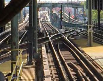
CONDUCTOR RAIL INSTALLATION INSPECTION FOR S&C
On LU and other railways where third (or fourth) rail is present the measured inspection of conductor rail within S&C is a safety and operationally critical activity. Measurements are to be undertaken to confirm the longitudinal, AUTHOR
Darren Sharp
CEng ICE/FPWI Permanent Way Consultant
Darren has 30 years experience within Permanent Way Engineering covering design, innovation, manufacture, renewals and maintenance. He has worked for British Rail, Scott Wilson, Jarvis, Transport for London and various consultancies. Darren’s work has mainly concentrated on London Underground for over 20 years, involved with project engineering management and as the Principal Engineer for S&C and more recently working with JBA consulting within New York City Transit and Network Rail Asset Enhancement team.
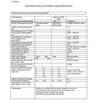
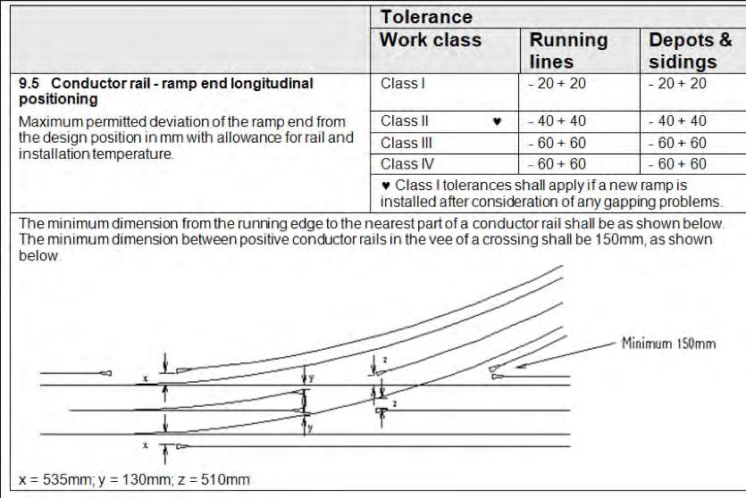
Image 2: S1164 Conductor rail ramp end longitudinal positioning within S&C on LU.

Image 4: S&C Digital Twin Concept.
vertical and horizontal positioning of the ramp ends and contact rail in relation to the running edge, toes and nose. Positioning and measurement of conductor rail within S&C is more critical than plain line. This is due to the additional risks introduced by gaps within the conductor rail that allow for the diverging route and swept path of the conductor rail shoe on converging or adjacent routes. If installed or maintained incorrectly this can lead to loss of shoes, gapping of trains and in some instances derailment due to shoe beams being caught beneath the conductor rail and running rails. The three critical dimensions, X, Y and Z (as detailed in image 2) and the vertical and horizontal offsets of the conductor rail are to be taken at every ramp end, and at 5m centres thereafter.
X = minimum horizontal dimension of 535mm measured from the diverging running edge to nearest part of the positive conductor rail ramp. Y = minimum horizontal dimension of 130mm measured from the nearest running edge to the nearest part of the negative splay ramp at the heel. Z = minimum horizontal dimension of 510mm measured from the nearest running edge to nearest part of the positive conductor rail ramp in front of the crossing. (See image 2). The minimum horizontal dimension between adjacent positive conductor rails in the vee of the crossing is 150 mm.
The third rail system on the southern mainline railway has similar critical measurements for lateral and longitudinal positioning.
Other ancillary components within LU, such as point machine ramps and slipper runs are installed to protect against low hanging shoes. The heights and offsets for these are also measured and recorded. A 2m conductor rail exclusion zone is maintained surrounding the point machine to safeguard operational staff against the risk of electrocution.
MODULAR TIE PLATE INSPECTION
The introduction of modular tie-plated bearers has introduced additional inspection requirements to ensure the correct installation process for the tie plate assembly has been followed. Torque setting of the screw bolts in the correct order, torque marking to indicate any movement and then recording these activities onto an inspection test plan are all mandated activities required for hand back and handover. Additional gauge and twist checks are undertaken through the tie-plated sections. This follows into the maintenance inspection where S&C Inspectors check the tightness of the screw bolts, the condition of the coil washers and for signs of voiding or displacement around the tie plate joint.

Image 3: Typical conductor rail arrangement at the toes.
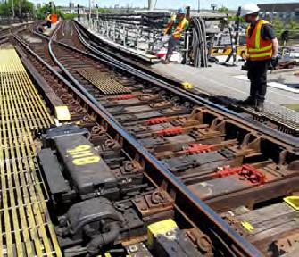
Image 5: 911B Pts at Coney Island, Brooklyn, NYCT. Day time reliability inspections on elevated structures.
TRACK INSTALLATION HANDOVER
As part of the track handover process, dynamic geometry recording is used to provide evidence of the track quality post installation and final tamp. The handover process also involves visual inspections with the asset owner/maintainer to ensure visual defects such as missing clips, ballast levels, rail head condition, bearer squareness and any other missing parts are to a satisfactory level for acceptance back into maintenance. This method can be subjective, especially where issues arising from the design or prefabrication cannot be addressed or were not communicated to the maintainer beforehand. This can be improved by the introduction of 3D scanning or drone surveys of the layout to act as a before-and-after comparison and also as a record for ongoing maintenance works. A drone or trolley mounted scanner can be used to survey the layout at prefabrication and installed to check the accuracy of the work.
S&C DIGITAL TWIN INTRODUCTION
(See image 4). Fully compiled with the correct data models and process information, the digital twin will form the backbone of the asset management tool.
All data associated with the ongoing management of the system will be stored within the digital twin to provide a one-stop integrated virtual model that is continually mapped to live data sources. This provides an accurate health status of the asset and reduces the need for human intervention to filter through various information, which is not always reliable or recorded. Track, Signals, Civils, Power/Electrification, Drainage, Mechanical and Communications are all asset areas that would benefit from the presence of their own digital twins to connect with their interfacing counterparts.
As part of the project handover process we rely upon MAIDs (Mandatory Asset Information Deliverables) or as previously known, Health and Safety files all presented in a PDF format of drawings and as-built data. Whilst other geographical information system exists that can be overlaid or linked to this information to the GPS location, the data only provides an asset register for the S&C at that point in time. This will hopefully become a thing of the past once the digital twin is in use. Network Rail and other European partners through the In2Track2 project will soon be trialing the use of the digital twin model.
SWITCH RELIABILITY INSPECTIONS
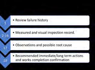

Image 6: Switch Reliability Inspection Process. Image 7: Water Ingress on NYCT S&C.
EFFECT OF WHEEL RAIL INTERACTION ON SWITCH RELIABILITY
Over the last ten years, there has been a growing trend towards changing the way in which we inspect our track assets by focusing on the root cause of failure that we are witnessing on our S&C. Whilst inspecting to a safety standard is paramount, inspecting to a reliability level is becoming an important maintenance activity. Standards are based on safety tolerances and on most infrastructure organisations, they do not allow prediction of a potential failure. In addition, the reactive inspections undertaken post failure rarely feed back the root cause and, in most cases, attempts to rectify the fault are made and not recorded. This, coupled with the ineffective interaction between track and signal engineers during inspection or rectification works, leads to a poorly managed asset.
To help reduce switch failures on both DLR and NYCT, a Switch Reliability Inspection process was introduced. This focused on the common failure modes associated with the differing types of S&C and incorporating these into the inspection process to prevent the failure from occurring. New tools were also introduced for measuring residual switch openings, heel joint gaps, slide plate gaps and other voiding or clearance measurements. The inspection form is summarised in image 6:
Water ingress into the tunnel network from the above connected street drains and leaking tunnel walls is a major cause of track and signal failures on NYCT. Water ingress into point machines and around the switch panels causes points failures due to the rapid degradation of the components, the track geometry and the integrity of the signal wiring and controls. The latent effects of water ingress damage are visually examined as part of the reliability inspection of S&C. An additional inspection process for inspecting the reliability of track circuits was also introduced, focusing on the failure modes of IRJs (Insulated Rail Joints), track wires, bonding and track conditions that lead to earthing of the track circuit. See image 7.
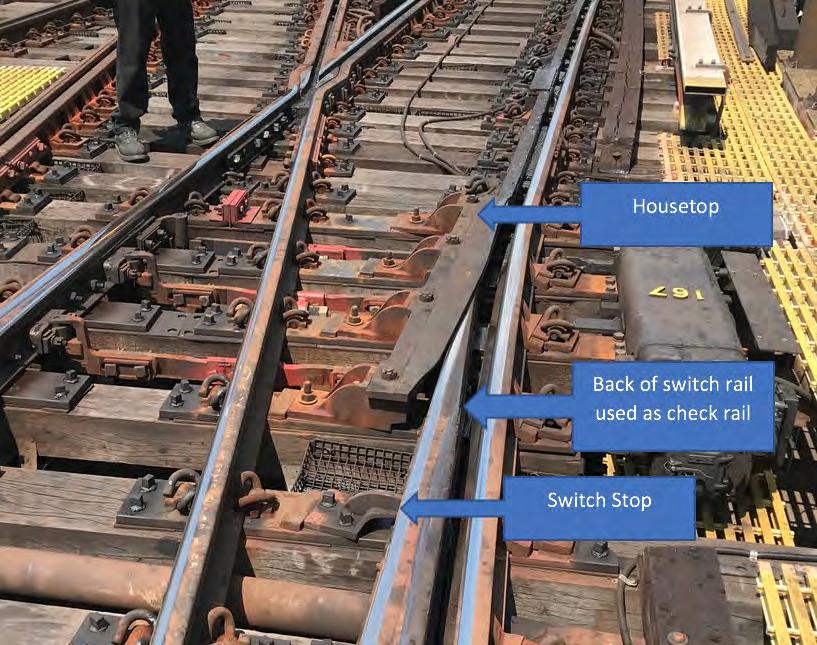
The importance of recognising how and when wheel rail interaction affects the reliability of switches was introduced as part of the switch reliability inspection training to both track and signals staff. The effect of flange back contact on the back of a switch rail on the New York City Transit (NYCT) system differs from the UK due to the presence of the housetop (see image 8). The housetop provides additional wheel guidance for the turnout route reducing wear and flange-climb derailments. The rear of the switch blade is used beyond the housetop extent which can transmit forces back to the POE if not correctly stabilised by the switch stops. This leads to stretcher bar, stock rail braces, detection and locking failures which are inherent failures of the track design.
S&C MAINTENANCE INSPECTIONS
Data from varying sources exists to enable the maintainer to manage S&C to within the mandated safety thresholds. Geometry data from Track Recording Vehicles measurements provides a dynamic snap-shot of how the S&C performs underload. When combined with rail defect data, switch (signals) failure history, AVI (Audio Visual Inspection) and manual geometry inspections, this will help to provide a more holistic approach for managing the reliability and maintainability of the system. Our next goals within the UK are to achieve an autonomous inspection process for S&C using pattern recognition, laser and optical measurement equipment combined to create a more accurate representation of the asset. The use of drones to cover inspection tasks that cannot be undertaken by automated means, such as items that are obscured or outside of the photogrammetry recording systems view, can assist in filling these gaps to fully automate S&C inspections.
condition monitoring can be combined to create a combined defects diagnostic system. Certain conditions within S&C that on their own do not present a risk of failure, can become an issue when combined with other conditions which then lead to an increased likelihood of failure or rapid deterioration. The various independent condition monitoring systems can be collated and assessed simultaneously using a multiple defect diagnostic tool to predict failure. This will all then become part of the Digital Twin degradation and diagnostics In the meantime, manual measurement techniques are still relied upon until the technology is ready for general use. It is important that we don’t lose sight of why we measure what we measure, and also to consider what else we could measure that we couldn’t before.
Table 1 lists the critical measurements to be recorded within S&C. The table identifies whether they are currently measured in the UK dynamically (train-borne equipment) or statically under standard maintenance inspections. The drive towards autonomous inspection, to help reduce the risk of workforce exposure to unsafe conditions and human error when measuring, is a positive move within the industry and one that should be treated with a high moral standing. Comments have been included to help consider whether the measurement is best taken in a loaded or static condition.
Certain dynamic track behaviors that cannot be measured on a vehicle, such as voiding, P1/ P2 forces, lateral movement and acceleration/ vibration of the track, are measured using varying methods as part of product trials, or in some cases, where the asset is having reliability problems. The old style void meter has been used for many years for this task, however, as installation tolerances become more accurate and with higher quality being demanded, so must the measuring devices. The use of mobile track behavior measuring devices is becoming more widespread with suppliers now providing solutions to assist the maintainer with accurate information on how the S&C is performing. This can become a useful monitoring tool when used correctly and helps predict a timelier intervention. Trials of digital void meters and other mobile monitoring equipment such as strain gauges, accelerometers, potentiometers and linear deflectometers are presently being considered for trial for this purpose as part of Network Rail and In2Track2 future enhancements.
MEASUREMENT
Gauge within Switch Panel
CURRENTLY MEASURED DYNAMICALLY
Y
Flangeway Clearance (FWC) N
Toe Opening (FWC at Toe) N
Residual Switch Opening (RSO)
Slide Plate to Switch Rail Gap N
N
Check Gauge Free Wheel Passage (FWP)
Check Rail Back to Back in Diamond N
N
CURRENTLY MEASURED STATICALLY
Y
Y
Y
Y
Y
Y
COMMENTS ON MEASUREMENT METHOD
Dynamic gauge spread, rail roll, RSO and distance block gaps provide a more realistic measurement under load. However, dynamic gauging through the front portion of the switch rail is known to include inaccuracies due to varying rail profiles at the measuring datum.
If the wheel flange back is in contact with the back of the switch rail, a forced and increased flangeway opening will be measured that provides a false indication of the dynamic flangeway measurement. Dynamic flangeways can increase where RSO is present within certain distances of the stretcher bar. Dynamically measured flangeway allows complete length of switch to be measured, rather than defined locations which is an improvement. Current static measurements using a flangeway slider gauge measures at a set height below the rail level. The flangeway gap becomes less when measuring further down the chamfered switch where the wheel flange is at its lowest point. Both methods have their issues. Measuring using photogrammetry may also present a problem when measuring 25 to 30mm below the crown of the rail.
Differs for each POE type. Minimum values can be set. Does not present a safety risk, critical only for the set-up of the points machine and reliability of the system. Measured level with the top of the switch to the stock rail, stock chamfer can affect reading slightly.
RSO in most cases reduces to zero under load and therefore varies under load. Measured ahead of vehicle is static and when measured within wheel passage is closed up and becomes quasi-static. Therefore difficult to measure dynamically. Switch tip openings can cause tip wear in facing moves leading to derailment.
Whilst not critical it establishes whether high friction of switch hogging is present. In most cases the gap closes under load as the switch is deflected to its supported position. This only occurs passed the contact point and therefore gaps at the toe generally remain under load and can cause high levels of vibration.
Not measured dynamically currently. Dynamic movement is negligible and occurs mainly in the check rail which can role under load.
Y Not measured currently as part of standard inspection process. Dynamic movement is negligible.
Gauge within Crossing Area Y
Switch Profile N
Cast Crossing Profile N
Fabricated Crossing Profile N Y
Y
Y
Y Dynamic measurement gives false reading in throat/neck of crossing. These can be filtered as a rule. Dynamic affect is not as noticeable in crossing due to lack ofrail role.
Dynamic will provide correct switch to stock relationship both vertically and horizontally. Static 053 method has known human factor issues.
Static 3D scanning preferred for accuracy. However, dynamic is less time consuming. Dynamic will provide a more coplanar measurement. Current 054 static method is not consistent or repeatable. Discreet profile changes on the nose and relationship between the wing at the transfer point can be measured with far greater accuracy with 3D scanning.
Dynamic provides for movement within components, eg dipped nose.
Cross Level Y Y Dynamic preferred due to voiding, twist etc.
Table 1: (Blue cells denote preferred measurement).
SUMMARY - WHOLE LIFE INSPECTION PROCESS
To summarise, the two images 9 and 10 show methods of inspecting and measuring S&C throughout its life span comparing the current disjointed process against a future improved data capture process.
To improve reliability of S&C further, the use of specific reliability focused inspections undertaken at a predetermined time to prevent failure should be implemented specifically on legacy systems where known failure modes cannot be managed or controlled. New S&C measurement techniques are being devised as we start to embrace technology that allows us to measure and inspect in a more consistent way. The evolution in photogrammetry measurement inspections, both static and dynamic, coupled with track condition monitoring and embedded sensor technology all assist in prolonging the life of S&C and reducing staff attending site, both of which are the key objectives to a sustainable design.
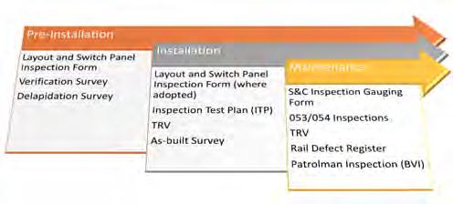
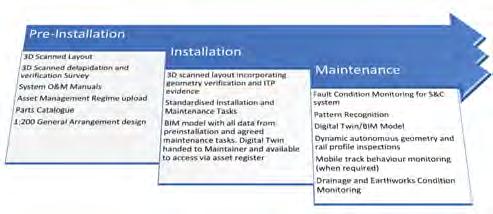
SPECIAL ONLINE KNOWLEDGE SHARES SPLOKS
1 of 3 SPOLKS - Supporting the industry workforce physically and mentally through the Covid-19 emergency – from an infrastructure management perspective
18 MAY THREE 20 MINUTES TALKS FOLLOWED BY 30 MINUTES OF Q&AS
Welcoming guest speakers Nick Millington (Network Rail), Duncan Weir (TFL) and Jennifer McKinney (Metrolink) and chaired by Joan Heery, President, PWI
PRESENTATION 1 – LEADING THROUGH COVID
Nick discussed the mass collaborative efforts needed in order to keep the railway open to the public and touched upon some of the key crisis management strategies that Network Rail have been undertaking in these challenging times. Nick said their focus has been on protecting the people and ensuring the railway key workers were able to safely carry out their duties so that the UK economy was protected. He impressed upon the audience the importance of the railway in the efforts to supply supermarkets, fuel power stations, remove waste from Central London, and most of all; keeping workers working.
Network Rail have been proactive in their response to the Covid situation and have rewritten numerous standards to reflect today’s reality. Changes to work activity risk assessments have been made and Covid Champions appointed to monitor social distancing measures on-site. Thermal imaging cameras have been set up at Network Rail facilities with more than 100 staff members, and smaller handheld versions are in use at smaller sites. Network Rail also responded quickly to the Covid situation by diverting project staff to assist in building the Nightingale hospitals. New PPE has been introduced for Network Rail staff. Following a collaboration with a lemonade bottle supplier, 30,000 visors have been manufactured to attach to hard hats. Staff members have been allowed to use their own vehicles to travel to work, and where this hasn’t been possible, 3,000-4,000 vehicles have been hired so staff could travel on their own. Where staff do not drive, arrangements have been made with black cab companies to have vehicles on permanent hire with technicians in the back seats and the polycarbonate screens between themselves and the drivers for protection. In-house they have converted approximately 2,000 vehicles with various types of screens to transport colleagues to work sites safely. The sheer numbers of these vehicles suggest this was no mean feat and shows the lengths that Network Rail have gone to, to protect its key workers.
PRESENTATION 2 – LONDON UNDERGROUND’S TRACK MAINTENANCE
London Underground’s early planning for the Covid pandemic has ensured the key maintenance works have been carried out to schedule with minimal disruptions. Considering 170 members of TfL staff were shielding or furloughed, this was not an easy task. Duncan explained that the management team had been involved in the military planning for SARS and were ready to implement those lessons learned to this situation. He went on to explain the 4 key principles they followed to avoid spreading the disease: AUTHOR


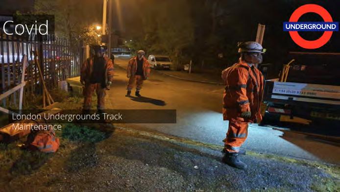
Alison Waterworth CEng MICE
Alison is a Chartered Civil Engineer and Project Manager. With a career spanning over 10 years, Alison has worked in many sectors of the transport industry including structures, highways, airports and railways. She has extensive experience leading largescale multidisciplinary engineering teams through all phases of design and construction; from early strategic business case to handover for operational use. Her most notable projects include the M10 Moscow to St Petersburg Motorway Construction, the Forth Road Bridge Cable Band Bolt Replacement project, HS2 Phase 2B ACI JV, and is currently the Project Manager for Northern Powerhouse Rail Manchester to Sheffield corridor.
Alison is an avid promoter of equality and diversity in the industry; speaking at many high-profile events including the Women in Construction Summit and UK Construction Week. She is also the Mott MacDonald Advancing Gender Champion.
1. teams were to undertake essential maintenance activities to ensure the safety of the line 2. there would be separate workforces where possible and practical 3. where separation was not practical, teams would be separated from other group and to maintain a 2 m distance 4. masks regardless of tasks.
Jim went on to explain the two main planning elements they considered; the physical measures needed to protect staff and keep trains running, and the psychological measures needed to reassure and support staff. The practical measures implemented included:
• stopping all face to face meetings and using conference calls. • splitting teams into morning and afternoon shifts (red and blue teams) and the use of cabins was prohibited; staff were to go straight to work and then home again. • site documents were emailed to staff at home and drop boxes set up with safety critical paperwork to be collected from offices. • tasks carried out sequentially instead of concurrently.
The psychological measures implemented were:
• addressing concerns in an open manner to keep workers and families safe. Townhall meetings (without the townhall) have been implemented. • maintaining communications with the whole team to ensure the personal touch is kept despite no physical contact. • positive messaging to staff. Initial communications focused on what was planned to be done in the immediate term to prevent the spread of Covid, but messages now are about future developments and positive goals.
PRESENTATION 3 – CORONAVIRUS – KEEPING GREATER MANCHESTER MOVING
Jennifer introduced us to the Manchester Metrolink network and the 1,300 services a day this network provides (pre-Covid). The timing of the Covid lockdown wasn’t ideal for Metrolink as the day before lockdown, the new Trafford Park Line route was launched 7 months ahead of schedule and almost immediately began operating at the new reduced Covid frequencies. Operating reduced services and reduced hours has been designed to limit the risk of exposure for Metrolink staff. In order to compensate for this, more double-unit trams have been put into operation to allow for better social distancing for those who do need to use the network. There has been a drop in patronage by 95% currently.
Like TfL, Metrolink understood communication to be crucial for the frontline workers and they set up new engineering updates and all meeting were switched to online calls. As well as to workers, the messaging to the public was important, and special safety signage was made to ask members of the public to respect Metrolink staff and maintain their distance. Welfare vans have been deployed to enable easy hand washing facilities for staff and antivirus cleaning points have been set up. A local gin distillery provided bottles of hand sanitiser to Metrolink. A security company is currently collaborating with Metrolink to protect the frontline staff from antisocial behaviour.
A Temporary Approved Non-Conformance (TANC) process has been introduced, using ORR coronavirus guidance to document these. Meanwhile, Metrolink are continuing to look ahead and are introducing tram mounted remote condition monitoring kits to gain a holistic view of conditions and assist in moving towards proactive and preventative working instead of reactive working. Unfortunately, the equipment is from an Italian-based company and therefore there has been a slight delay to commissioning this equipment, but hopefully this will be resolved soon.
JOAN’S SUMMARY
Joan closes the discussion by surmising that all companies have been very responsive and have embraced change positively. It is clear from the current Covid situation that Railway workers provide essential services to health workers, are key to the movement of goods, and support the day to day business of other industries; all essential elements to continue to support the UK’s economy.
Her final, and most important point is that companies are focusing on health and wellbeing as much as the work itself, and this is a great step in the right direction for the future.
VISIT THE PWI YOUTUBE CHANNEL TO VIEW ALL OF OUR RECORDED MEETINGS AND TALKS
shorturl.at/eyFPS
2 of 3 SPOLKS - Delivering infrastructure renewals and projects in a socially distanced world
26 MAY THREE 20 MINUTES TALKS FOLLOWED BY 30 MINUTES OF Q&AS
Welcoming guest speakers Steven Graham (Colas Rail), Tony Morgani (Murphy Group) & Greg Rutherford (AECOM) and chaired by Stephen Barber, CEO, PWI
3 of 3 SPOLKS - Maintenance challenges including supply of rail plant and equipment to the front line
2 JUNE THREE 20 MINUTES TALKS FOLLOWED BY 30 MINUTES OF Q&AS
Welcoming guest speakers Dominic Trueman (London Tram), Phil Allanson (Swietelsky Babcock Rail) & TBC (Network Rail) and chaired by Dr Brian Counter, Technical Director, PWI
PERMANENT WAY INSTITUTION
CORPORATE MEMBER
A strategic decision-support tool for the risk-informed asset management of railway track infrastructure
Railways serve as a key sustainable mode of transportation for passengers and freight in urban, suburban, regional, and national contexts. With the rise in road traffic, which is seen as a less green form of transport and associated congestion, there is an increasing demand for railways to expand their capacity, availability and carry goods and passengers at ever higher speeds. Such increases in usage result in faster railway track degradation rates and higher maintenance costs.
As a result, the UK is projected to spend £18.5bn on operation and maintenance during 2019-24, an increase of 25% compared to the previous five years2,3. Since maintenance funding is provided from the public purse, maintenance investments should be made in an equitable and transparent manner which maximises benefits to all stakeholders whilst minimising the costs to the environment.
Railway track condition, and therefore maintenance strategy, directly impacts track use costs, including train operation, accident, environmental and delay costs4. Therefore, maintenance decisions can only be taken responsibly when the costs and benefits of maintenance alternatives (ie total railway transport costs) are compared on a long-term, whole lifecycle cost (WLCC) basis.
Further, decisions and strategies for renewing, maintaining and operating railway infrastructure need to consider any ambiguities inherent in the data, including future uncertainties. In part due to the segregation of the railway AUTHORS
Manu Sasidharan, Michael Burrow, Gurmel Ghataora - School of Engineering, University of Birmingham and Rishi Marathu, Nitesh Menon - Intellex Consulting Services Limited
Dr Manu Sasidharan
is an Honorary Research Fellow at the University of Birmingham and Research Associate at the University of Cambridge. He read for his PhD in Civil Engineering at the University of Birmingham by adopting a whole-life and whole-system approach to identifying cost-effective and risk-informed railway track maintenance strategies. Dr Sasidharan conducts research on developing risk-informed approaches and value-based decisions for managing and appraising investments for critical transport infrastructure. He is a recipient of the Prestige Award for Young Researchers from the World Transport Research Society.
Dr Michael
Burrow is a Senior Lecturer in the School of Engineering at the University of Birmingham and obtained his MA in Engineering from Cambridge University and PhD from University of Birmingham. He leads the Sustainable Infrastructure and Asset Management theme within the University of Birmingham’s BCRRE Centre of Excellence in Rail Decarbonisation. His research interests are primarily focused on road and railway asset management and he leads the Infrastructure Pole of the European Railway Network of Excellence (EURNEX). He also leads the world renowned team of road specialists at Birmingham which developed a suite of cutting edge road asset management decision support tools, the products of which are used world-wide.
Dr Gurmel Ghataora
is a Senior Lecturer in the School of Engineering at the University of Birmingham. He graduated from the University of Wales, Cardiff with a BEng (Hons) and PhD in Civil Engineering. He has a vast experience of working in the industry with Douglas Technical Services Ltd and Ove Arup and Partners. He has undertaken consultancy work for a range of companies including: DTS Raeburn Ltd., Jackson Contractors (Preston) Ltd., ICI, Ove Arup and Partners and Shropshire County Council. Dr Ghataora’s research focuses on the use of marginal materials in civil engineering, ground improvement and railway track foundations.

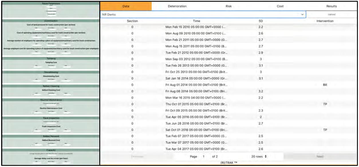
Image 2: Data entry-window for RITRAK

Image 3: Track deterioration modelling within RITRAK
industry, in which the management of the infrastructure is apart from the ownership and operation of rolling stock, existing asset management decision support tools in the railway industry tend to focus on particular elements of the system and do not perform such a holistic analysis.
To address this, a unique risk-informed decision support tool that uses a Whole Life Cycle Cost Analysis (WLCCA) approach under uncertainty has been developed to take into account the costs and benefits of track maintenance strategies to track maintainers, train operators, users and the environment. The concept of the approach is summarised in image 1 and the resulting tool, known as RITRAK, provides strategists and asset managers with an equitable and transparent means of evaluating the economics of maintenance strategies.
As illustrated in image 1, RITRAK adapts an approach where the (uncertain) costs and benefits of different candidate maintenance strategies are compared to achieve the most appropriate maintenance strategy ie the strategy with the lowest total railway transport cost. The WLCCA model at the heart of RITRAK considers the direct and indirect costs to all stakeholders and includes track construction; track inspection; track maintenance (realignment; ballast renewal and cleaning; routine maintenance); capacity loss; spillage; risk of derailments; train operation; environmental costs; transport mode change and end-of-asset-life value.
Changes in track quality over time due to track deterioration or maintenance are determined using a probabilistic based model. Monte Carlo simulation and Fuzzy Logic are used within RITRAK to deal with uncertainty through probabilistic risk assessment allied to expert opinion5 .
Images 2-5 illustrate a number of windows within the web-based RITRAK tool. The tool features a user-friendly interface to upload datasets associated with track condition, track maintenance history and the whole lifecycle cost analysis (see image 2). The window showing the track deterioration model that predicts the track behaviour when subjected to different maintenance strategies is seen in image 3. The risk assessment window shown in image 4 captures experts’ opinions regarding the severity and probability of derailments associated with different maintenance strategies. The results are presented in a dynamic interface (image 5) that allows user-interaction and report downloads.
RITRAK can be used to support strategic planning and programming levels of railway asset management. For example, in the cases when there is a shortage in the annual track maintenance budget, RITRAK can be used to inform plausible maintenance strategies that realise the maximum benefit, in terms of minimising total railway transport costs, for the available budget. Senior managers and decision makers can also use RITRAK to improve long-term investment choices. For example, the tool allows the implications of reductions in maintenance budgets on total railway transport costs to be scrutinised and investment to be targeted to the areas of the railway network providing the greatest benefit.
The RITRAK tool was applied to case studies on three different routes on the UK mainline network (commuter, intercity passenger and mixed traffic routes) and demonstrated that economically-beneficial maintenance standards could be adopted if railway track use costs are considered, and by doing so validated the applicability and usability of the developed approach.
The annual train operation costs (fuel consumption and train maintenance costs alone) could rise by up to £500 per metre if the track quality deteriorated from good to poor condition. A sensitivity analysis was carried out to quantify the contribution of maintenance and track use to the total transport costs
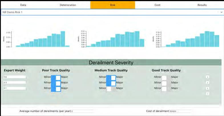
Image 4: Risk of Derailment model within RITRAK that captures expert opinion

Image 5 Interface with results from the WLCCA employed within RITRAK
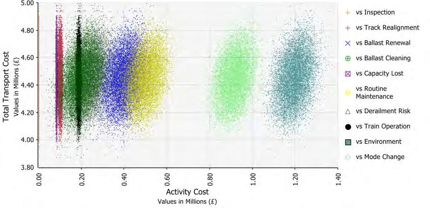
Image 6: Contribution of different whole-life-cycle cost elements towards the total railway transport costs
of a 200-metre-long track section. Image 6 presents the results of 10,000 possible scenarios generated using Monte Carlo simulations.
The analysis found that the environmental impacts of train operation (associated with CO2, NOX and SO2 emissions) due to deteriorating track quality had the highest contribution to the total railway transport costs (see image 6). The analysis also indicated that approximately £6,400,000/year could be saved on the London to Birmingham route if a total railway transport cost approach is adopted to maintenance decision-making. The detailed results of these case studies are given in Sasidharan, Burrow and Ghataora (2020)4 . In summary, the whole-lifecycle, whole-system approach encapsulated within the RITRAK decision support tool, enables cost-effective railway track maintenance strategies to be determined which are transparent and equitable through consideration of the costs and benefits to all stakeholders and the environment. It is an essential component of any holistic asset management approach.
ACKNOWLEDGEMENTS
The authors are grateful for the invaluable inputs from the RITRAK project steering group of Dr Mohammed Wehbi from Network Rail; Prof. Clive Roberts, Prof Nigel Cassidy, Dr Francesco Maria Colaccino, Dr Alan Tibbats and Kate Jermey from the University of Birmingham; and Prof Simon Iwnicki from the University of Huddersfield. The development of RITRAK was funded through an EPSRC Impact Acceleration grant and by Intellex Consulting Services Ltd.
REFERENCES
1. ORR (2017a) ‘Network Rail Monitor’Quarters 3-4 Year 3 of CP5 16-17’, London, UK 2. ORR (2017b) ‘UK Rail Industry Financial Information 2015-16’, Available at orr.gov. uk/__data/assets/pdf_file/0020/24149/uk-railindustry-financial-information-2015- 16.pdf 3. Sasidharan, M., Burrow, M. P. N. and Ghataora, G. S. (2020) ‘A whole life cycle approach under uncertainty for economically justifiable ballasted railway track maintenance’, Research in Transportation Economics. Elsevier Ltd, 80 (January), p. 100815. doi: 10.1016/j.retrec.2020.100815 4. Sasidharan, M., Burrow, M.P.N., Ghataora, G. S. and Torbaghan, M.E. (2017) ‘A review of risk management application for railways’, Railway Engineering, Edinburgh, UK