arthaslima05@gmail.com
https://linkedin.com/in/ thaslima-nasrin
https://issuu.com/thaslima/docs/portfolio_-_thaslima_bagrutheen
arthaslima05@gmail.com
https://linkedin.com/in/ thaslima-nasrin
https://issuu.com/thaslima/docs/portfolio_-_thaslima_bagrutheen
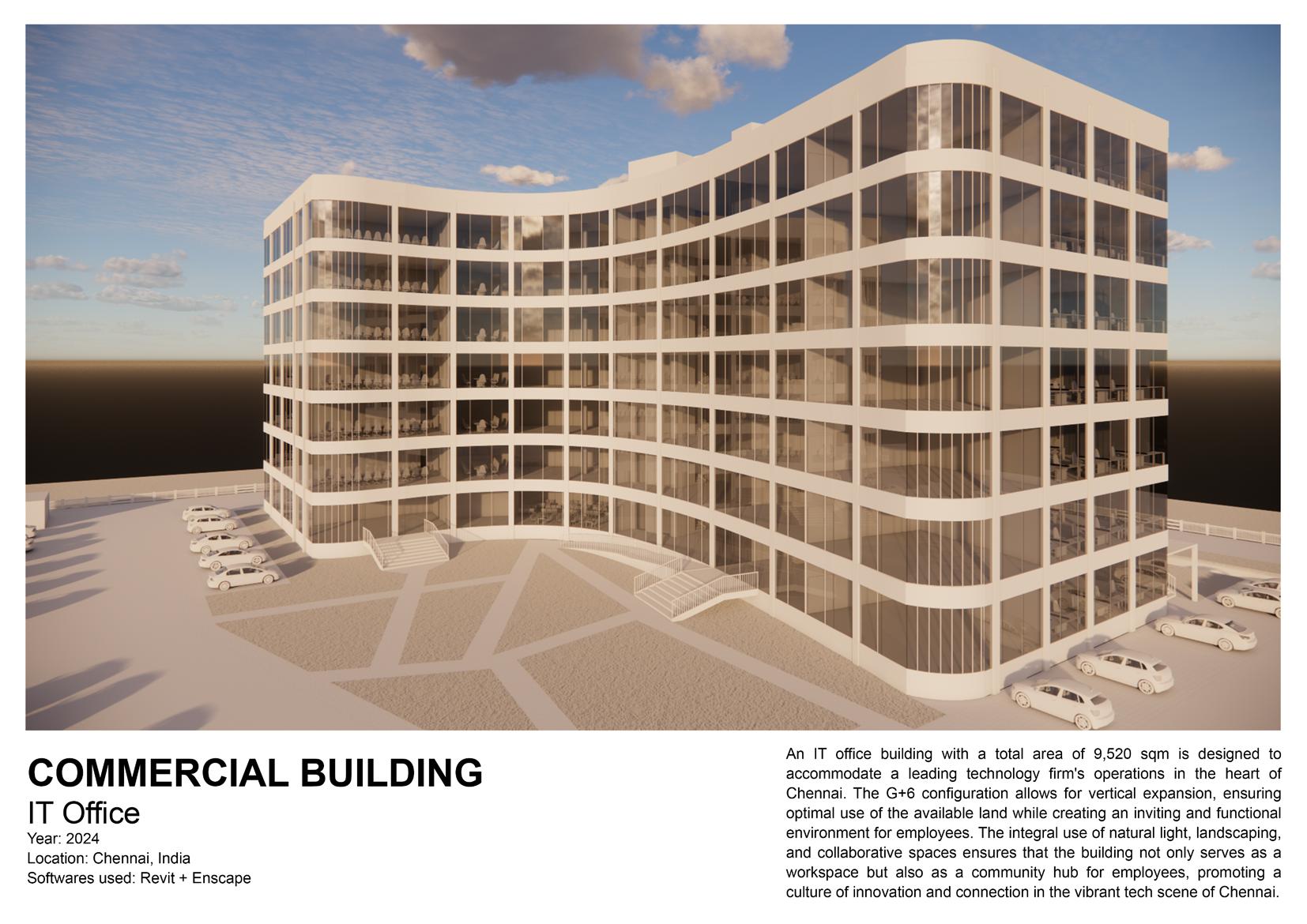
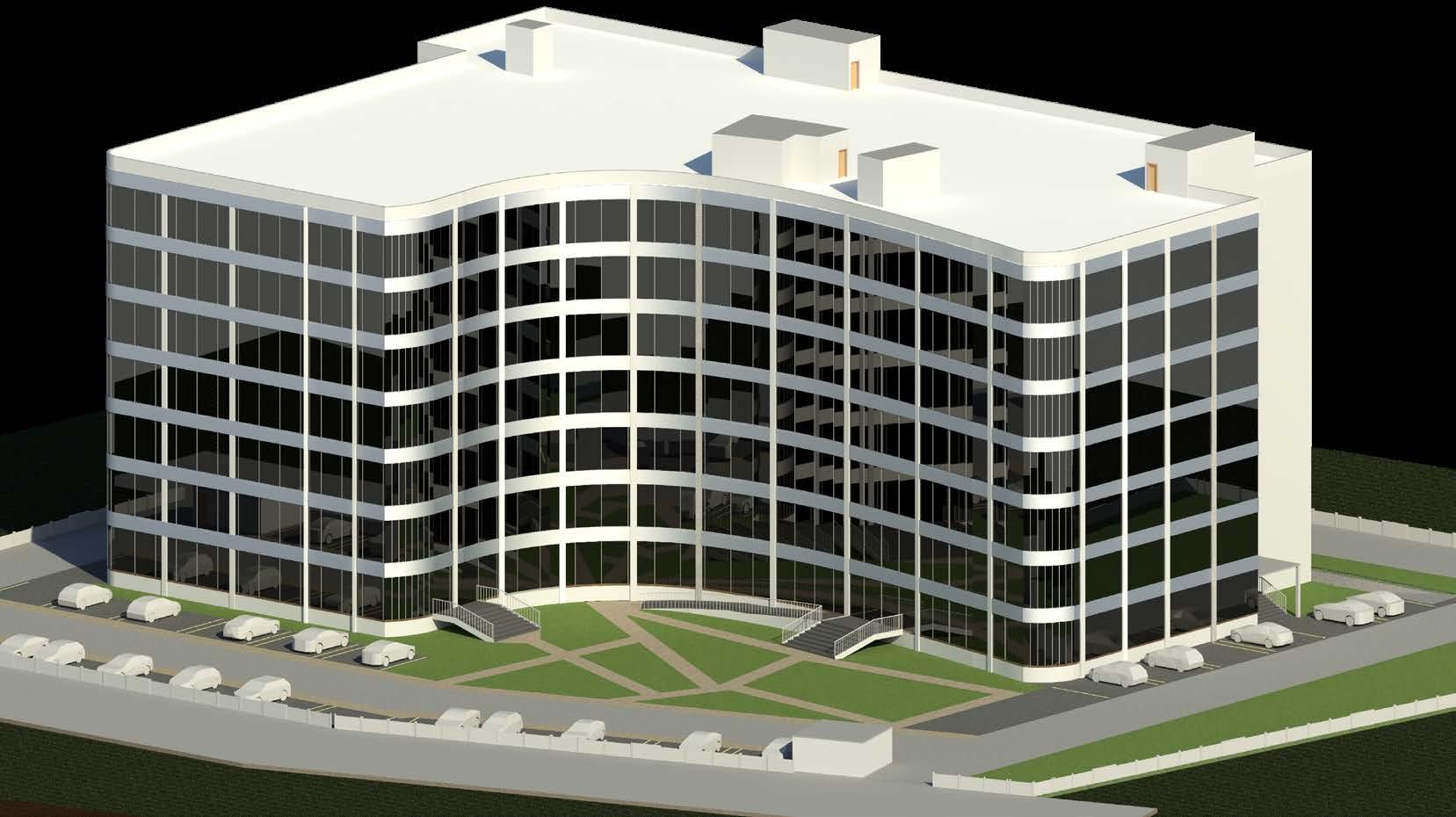
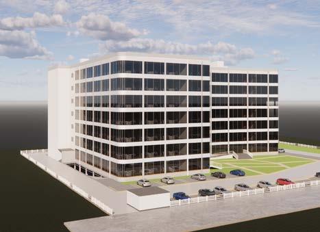
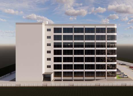
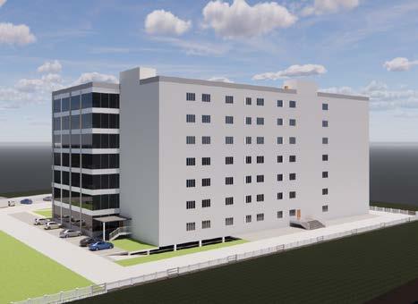
COMMERCIALBUILDING - ITOFFICE
• MODELING (Architecture& Structure)
• DOCUMENTATION (LOD 300)
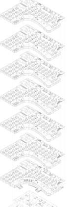
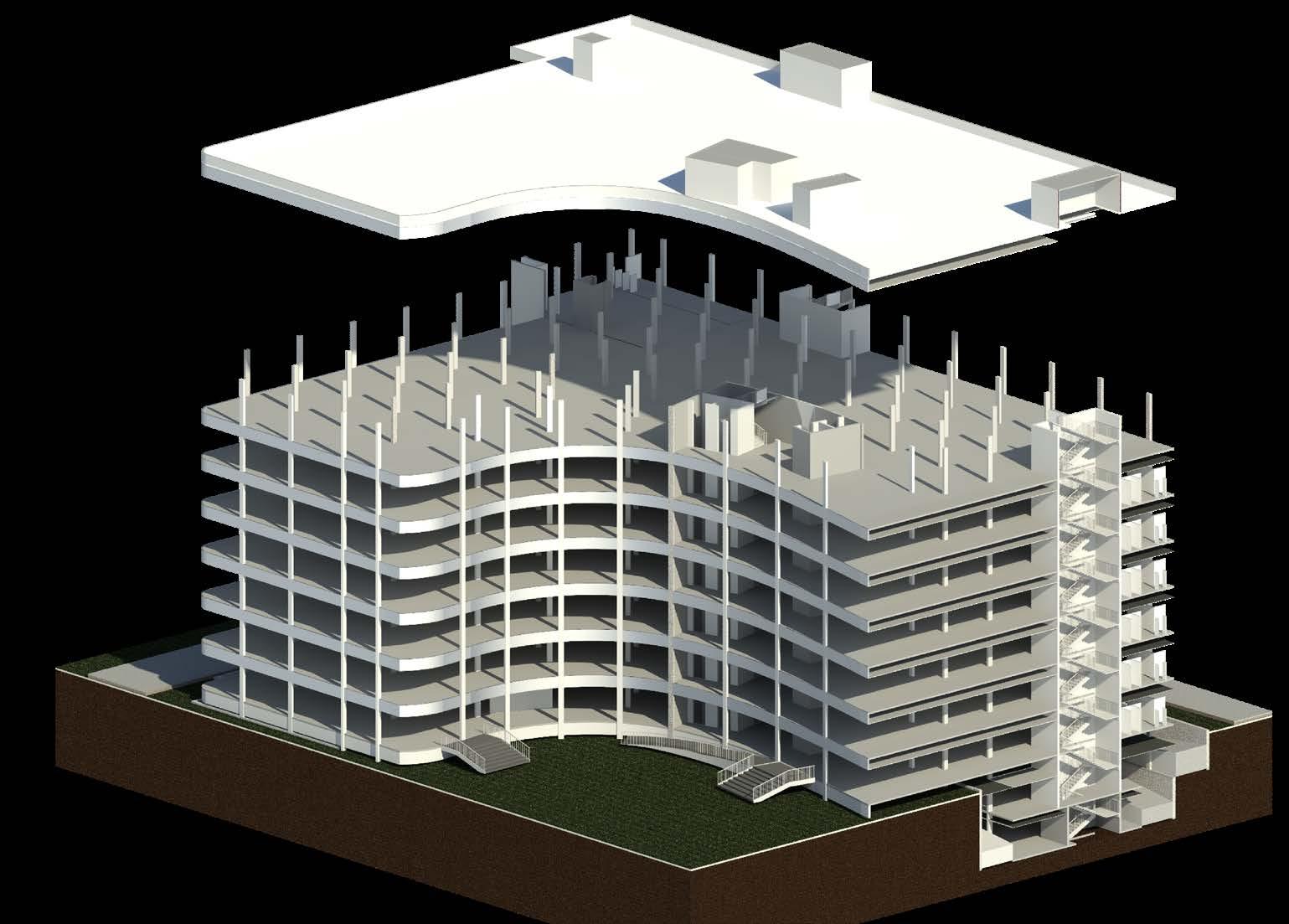
• AXONOMETRIC VIEW (Displaced Levels)
• COORDINATION CLASH CHECK
• INTERFERENCECHECK
• NAVISWORKS4D SIMULATION
• QUANTIFICATION
• SCHEDULES
• PARAMETRIC FAMILYCREATION
BIM INTERNSHIP- X-Architects, Dubai, UAE
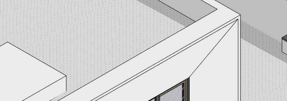
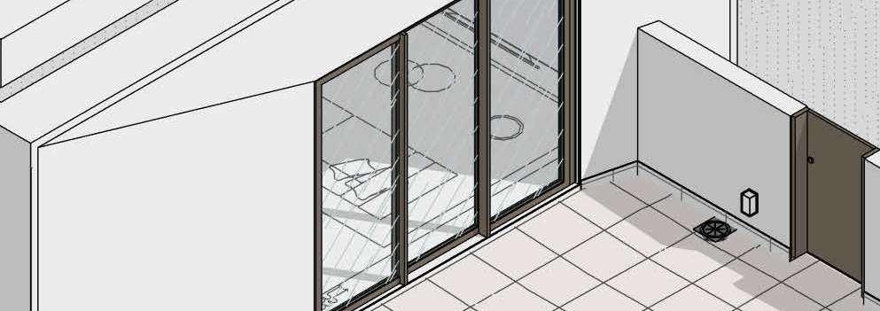
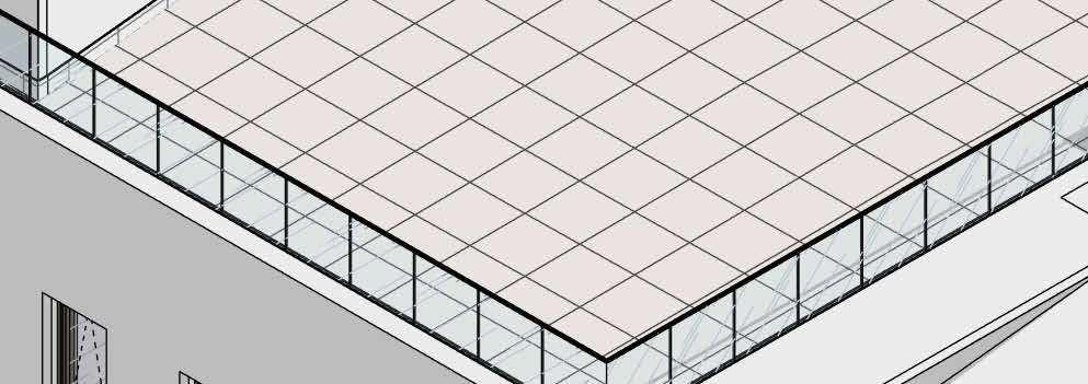
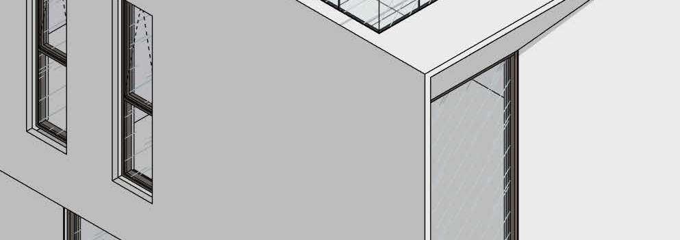
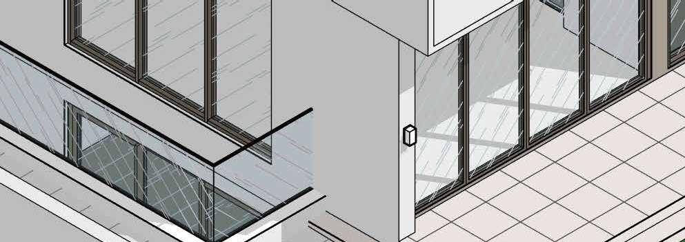
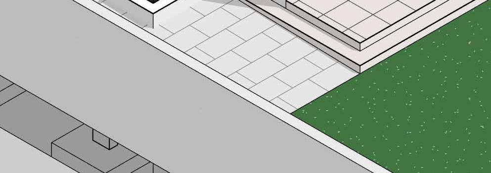
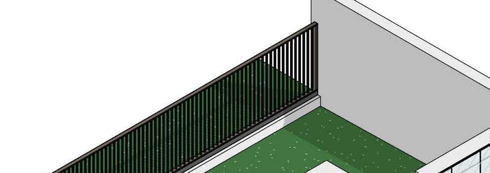
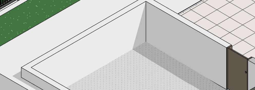
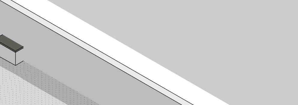
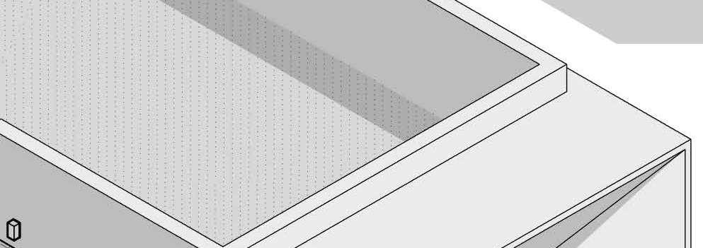
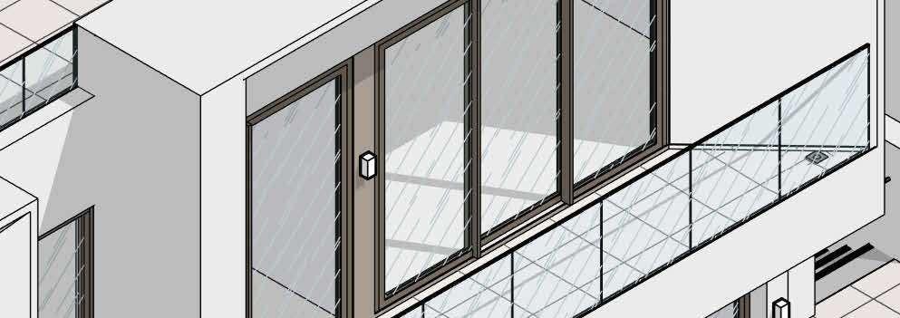
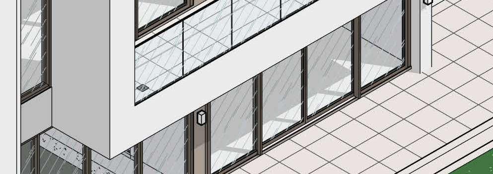
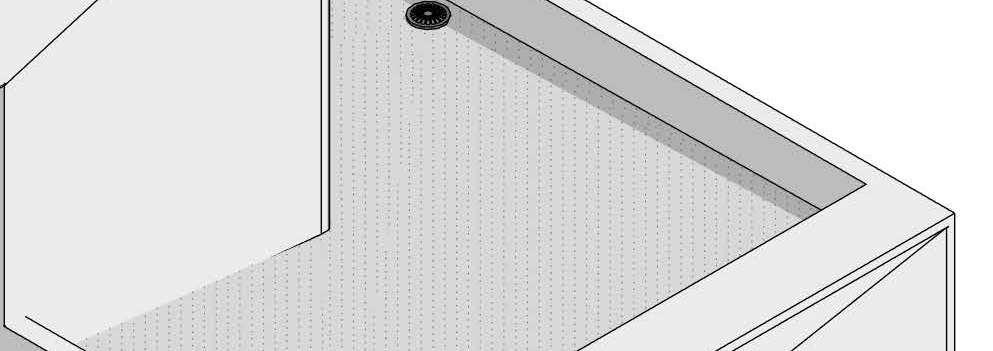
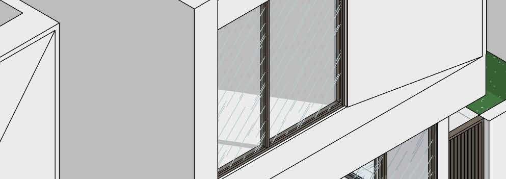
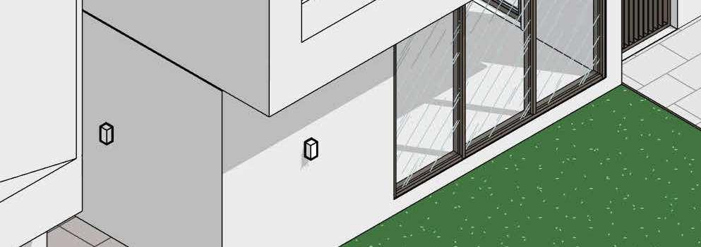
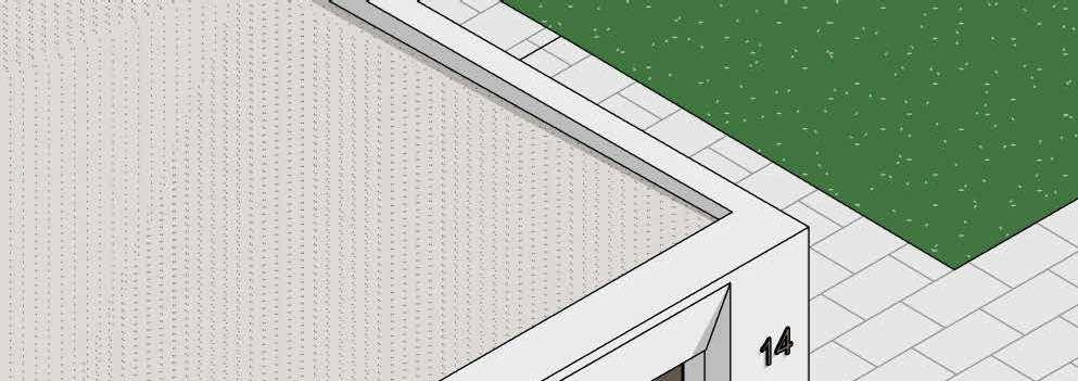
Floor plans, Facade types & Isometric views
JUNIORARCHITECT-ANTEngineering Consultancy, Dubai, UAE
Design proposal
Area calculation
Renders
INTERNSHIP-ARCOPAssociates, Bangalore, India
Working drawings






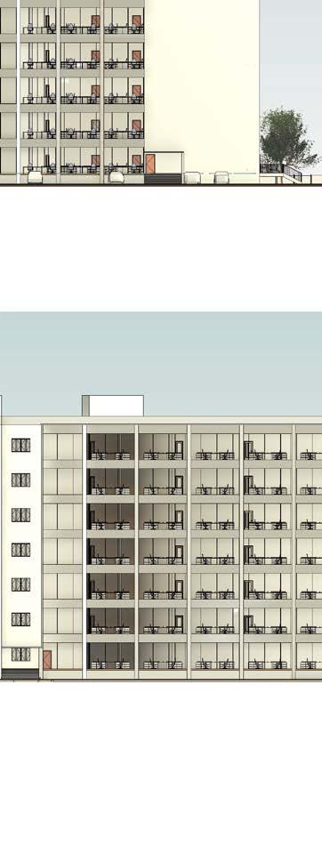

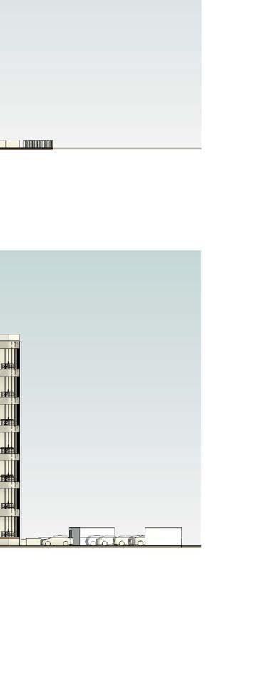

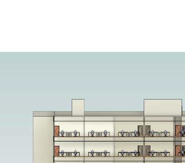
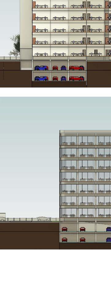
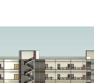
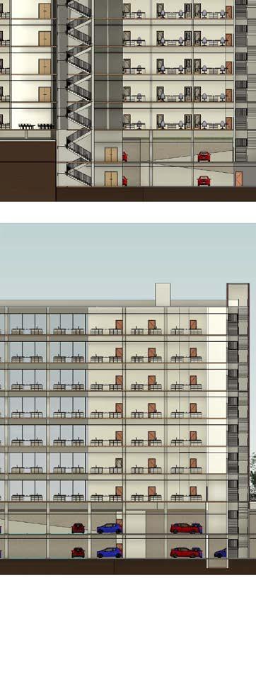

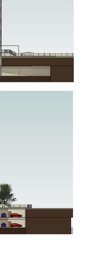
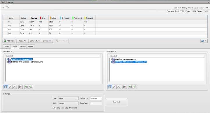
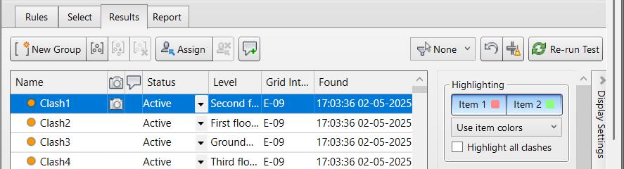
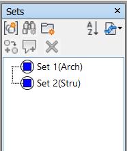
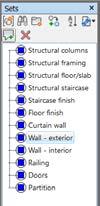
Created search sets within to run a test between the disciplines

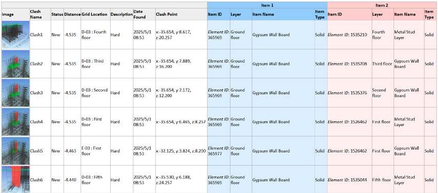
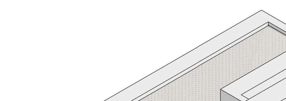
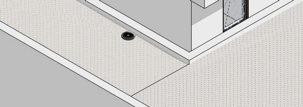
Initial clash detection

Resolved clash detection
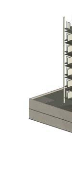
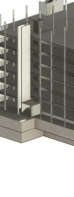
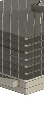
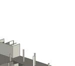
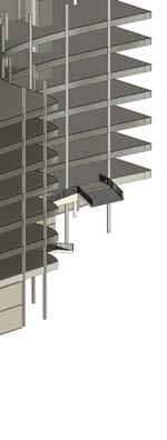

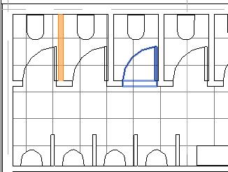
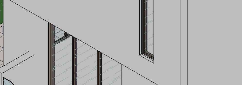
Location plan
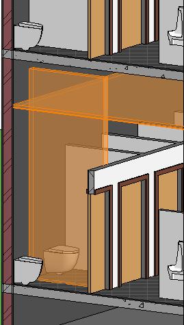
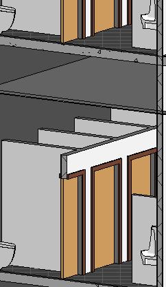
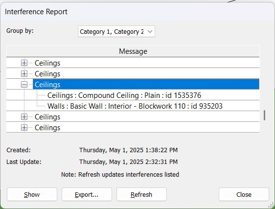
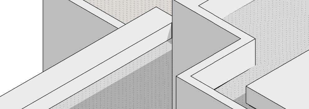
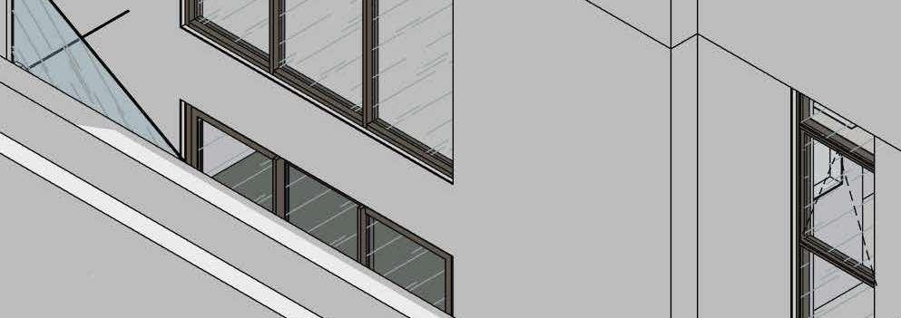
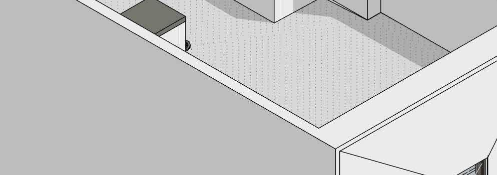
Issue: Partition blockwork wall clash with ceiling.
Solution: Adjusted with wall height.
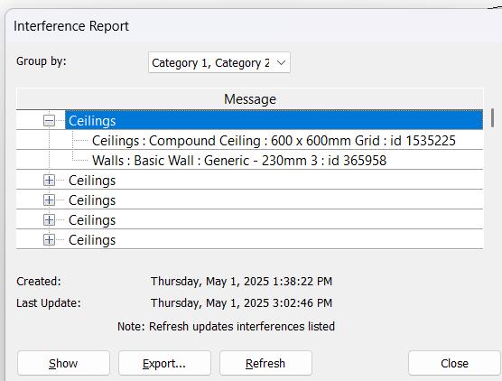
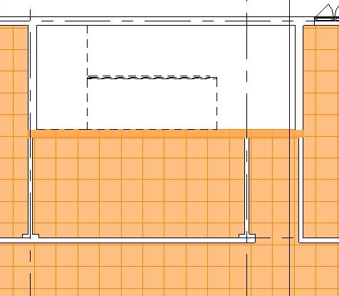
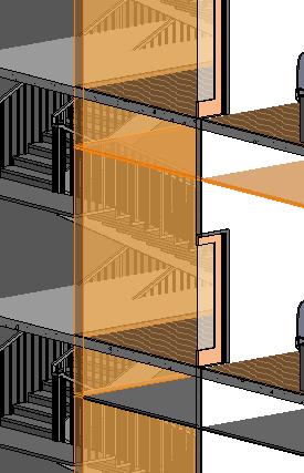
Location plan Before
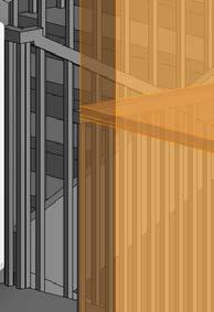
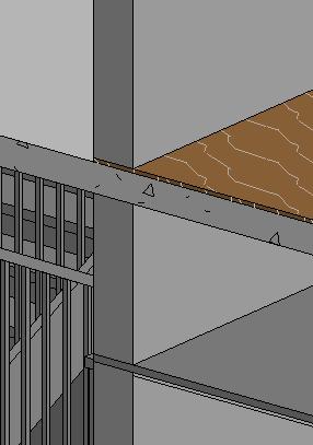
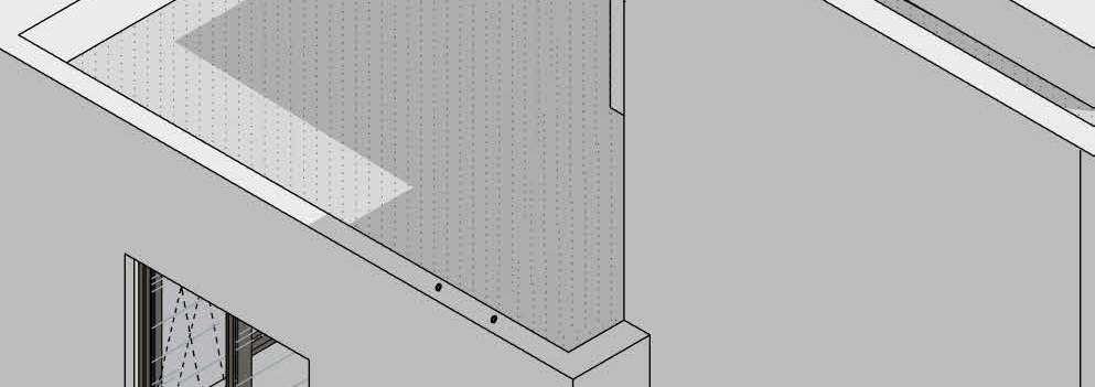
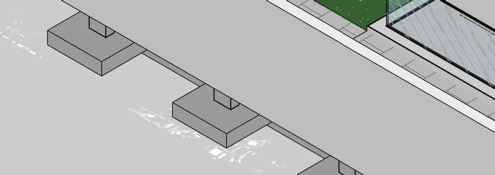
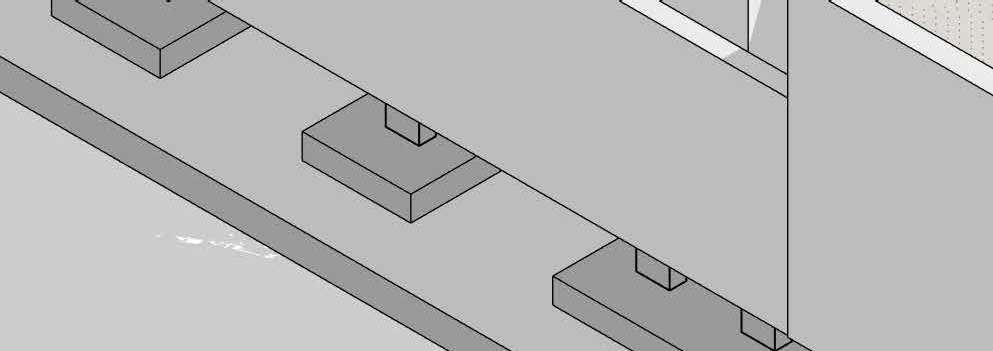
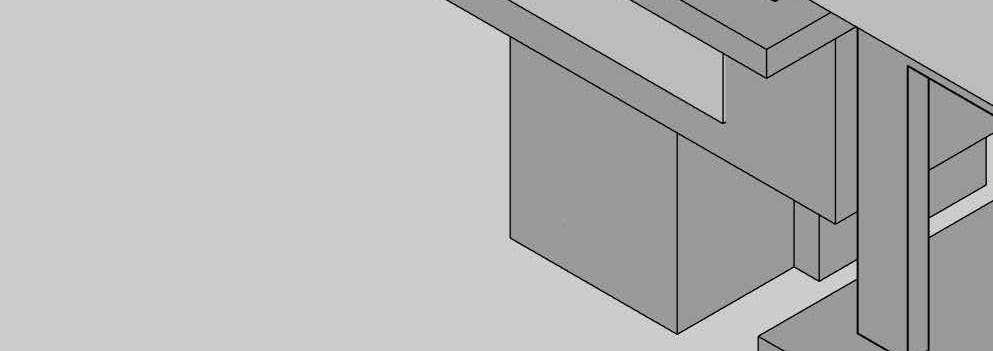
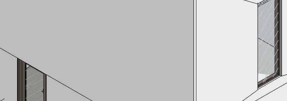
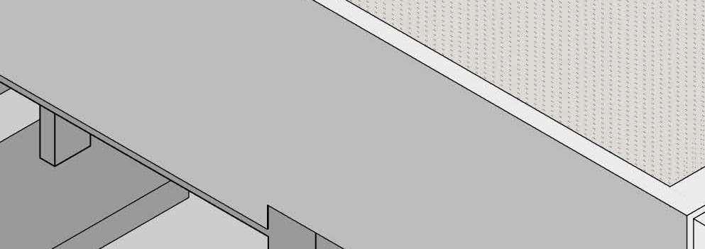
Issue: Floor slab clashing with wall
Solution: Proper trimming and alignment ensured that the floor slab no longer clashes with the wall, resulting in a coordinated and clash-free model
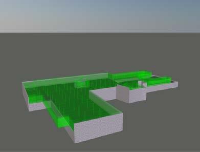
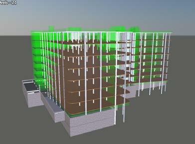
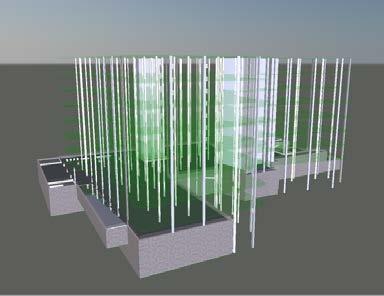
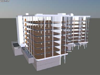
Using Navisworks for 4D simulation means blending time-based details into the 3D model. This creates a visual representation of construction sequences and project schedules. Essentially, it’s like watching the project unfold over time. This helps everyone involvedunderstand how things will progrss, spot any issues or delays early on, and fine-tune the plan for smoother execution.
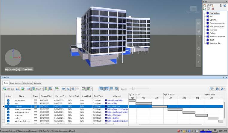
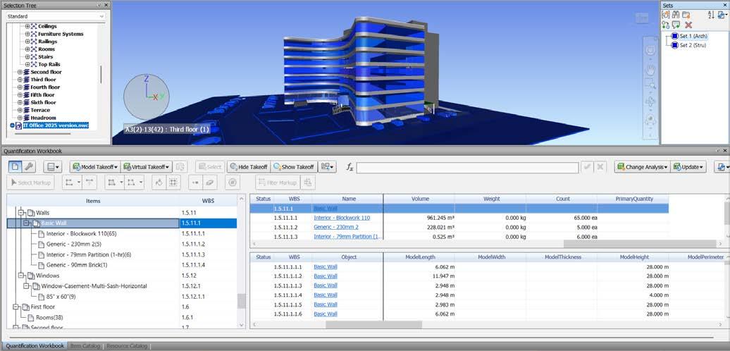
In Navisworks, the Quantification is used to take out quantities from a 3D model, which helped with cost estimation, material takeoff, and project planning. I created catalogs for both architectural and structural items to perform quantity takeoff, which is a key aspect of 5D cost planning. By mapping search sets to specific items within the architectural and structual models, I accurately quatified each component, providing detailed insights for cost analysis and project management.
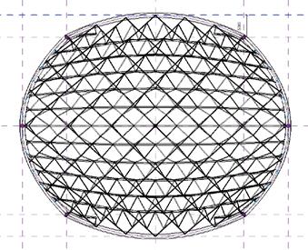
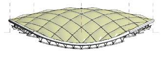
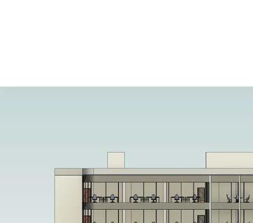
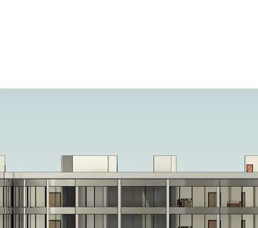
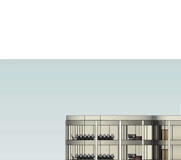
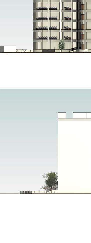
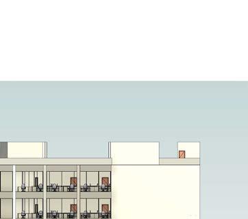
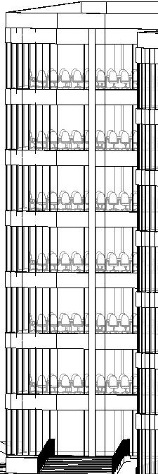
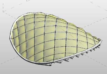
Elevation - Left
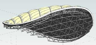
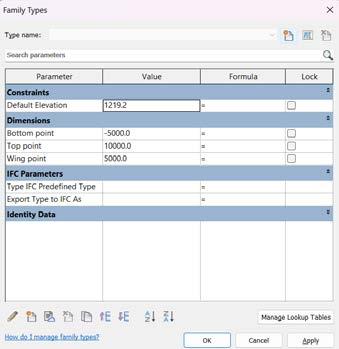
Creating organic form tensile structure using conceptual massing, pattern based model family and adaptive modeling.
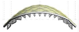
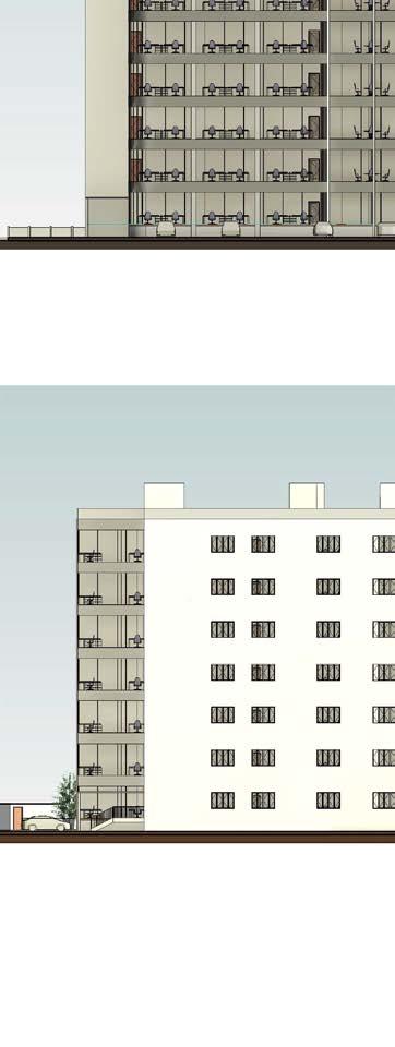
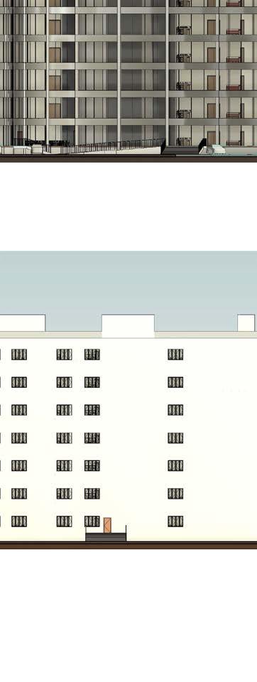
Elevation - Front
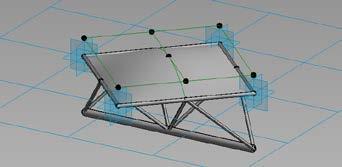
Pattern based model family
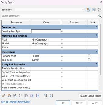
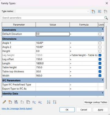
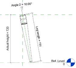
Creation of leg families using Revolve and angle constraints. Then created a two different families one inside other to control the angle parameters.
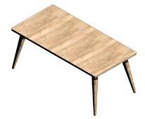
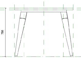
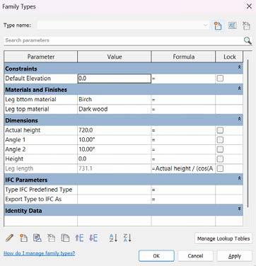
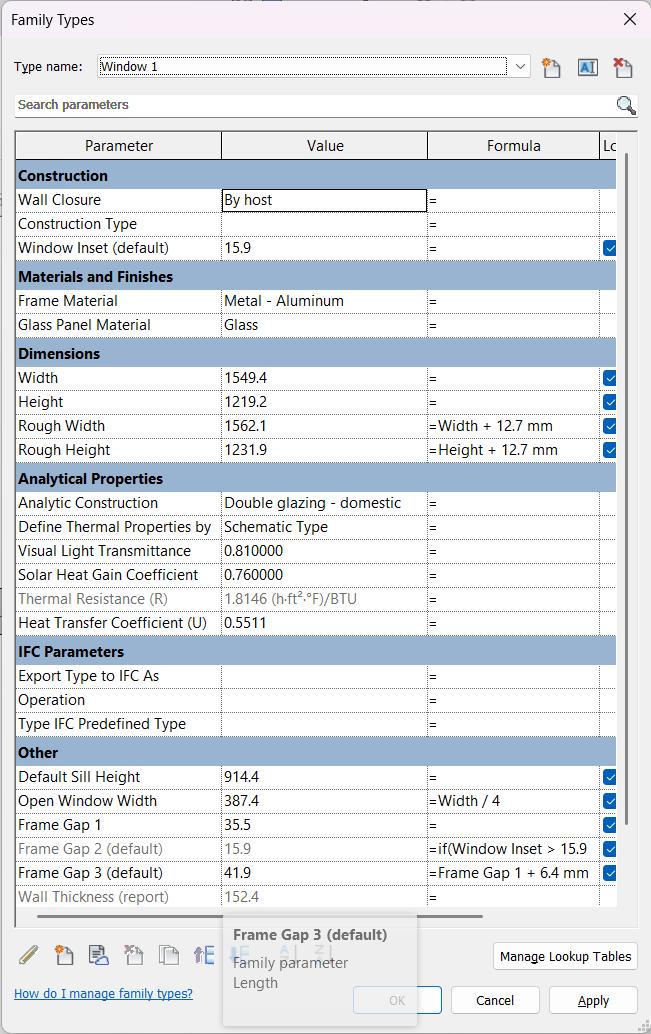
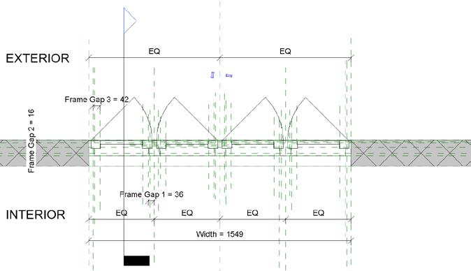
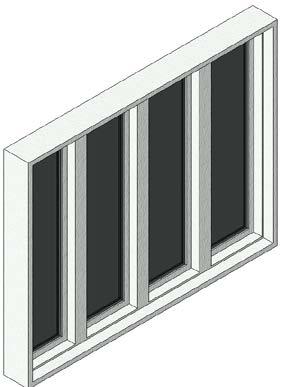
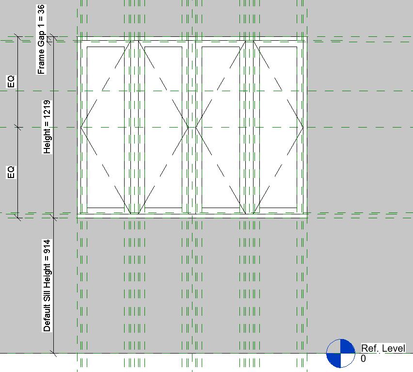
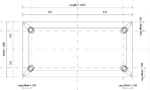
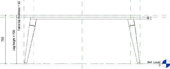
Creation of table family using Extrude and angle constraints. Then loaded the families with its angle and height constraints.
Dubai, UAE
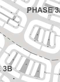
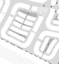
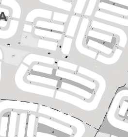
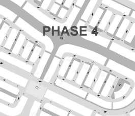
OASIS by EMAAR (Phase 3), Dubai
• Floor plans
• Facade types
• Isometric views
ANT Engineering Consultancy, Dubai, UAE
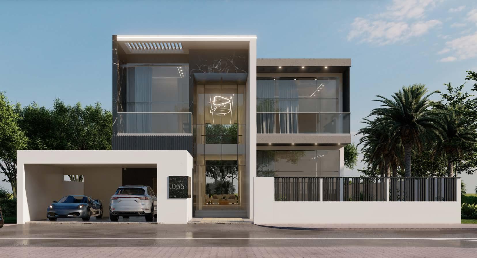
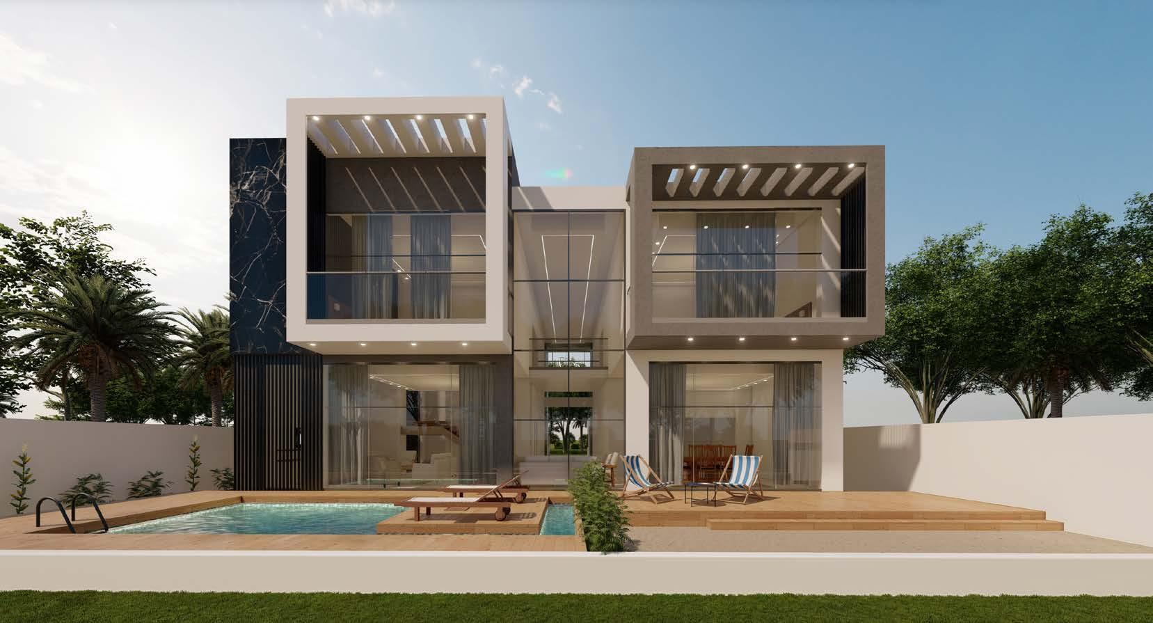
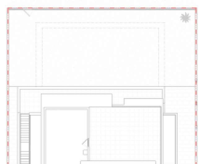
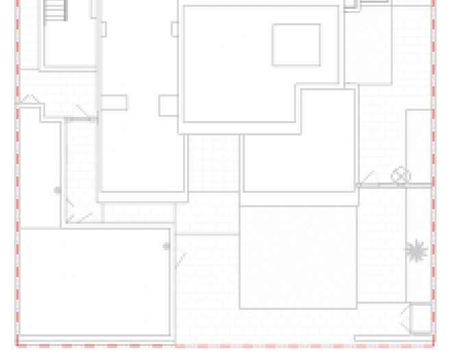
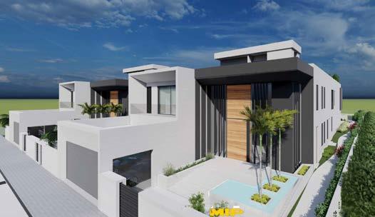
i) Proposed B+G+1+R Villa atAl Maktoum City, Dubai
•Area calculation
• Pump room & U.G. Water tank details
ii) Proposed G+1 Villa atAl Furjan, Dubai
• Floor plan
• Renders
iii) Preparing sheets for DM and DCD submission
ARCOPAssociates, Bangalore, Karnataka, India
i) Jubilant Biosys, Bangalore
• Elevation
• Section
• Facade Sections
ii) Elephants’Residential Complex, Kinshasa, DR.Congo
• Section
• Roof level plan
• Staircase detail
•Toilet details
• Schedule of openings
• Flooring plan
iii) SOFICOM, Kinshasa, DR.Congo
• RCPLayout



































































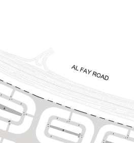

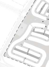
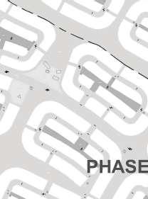






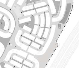
SUBMISSTION TYPE WORK DESCRIPTION
PARKING REQUIRED
EXISTING PARKING
ADDITIONAL PARKING
TOTAL PARKING PROPOSED
LOCATION/BLOCK NAME PROPERTY TITLE
NO. OF FLOORS PROPOSED
LAND USE PROPOSED
PLOT COVERAGE PROPOSED
VILLA AREA
APPROVED AREA SWIMMING POOL AREA DEMOLISHED AREA
BUILT UP AREA ADDITIONAL AREA