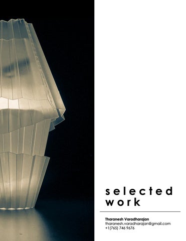
selected work Tharanesh Varadharajan tharanesh.varadharajan@gmail.com +1(765) 746 9676
01
02
03
BioMatters
Fabrication
The Robotically Fabricated Structure (RFS)
04
The RF
4
FS 2.0
05
06
07
Higher Ground Community Centre
The Boulder Effect
Rest In Peace
BioMatters
Biomatters is a research project developed during the Master of Science in Digital and Material Technologies program. The project involves material research and development, tool-head research and development and toolpath development. The brief of the semester was to deign for a single family housing using 3D Printing technologies keeping in mind the carbon footprint and the waste architecture and construction produce annually. Each group developed different strategies revolving around the use of 3D printing techniques, like optimizing structural systems and production line using alogorithms and engineered fabrication systems.
Project period
Graduate Research Thesis
Project typology
Research and Construction
Project focus
Construction Techniques
Project team
Tharanesh Varadharajan, Muhammad Dayyem Khan, Zachary Keller, DART Labortory
Publications:
ACADIA 2023: HABITS OF THE ANTHROPOCENE DEZEEN - DART Lab creates biodegradable concrete casts using sawdust
Additives
Saw-Dust
Cellulose
Calcium Carbonate
Magnesium Oxide
Paper Pulp
Calcium Chloride
Shrinkage
Solidification Time
Shrinkage
Solidification Time
Shrinkage
Solidification Time
15%
24hr
15%
24hr
17%
36hr
In the material research phase we researched on wood-based and paper-based material composites and altered our recipe to have more sustainable ingredients. We used a simple syringe extrusion with about 20 different compositions to test the consistency of the material and ran basic shrinkage and solidification tests on these samples.
Biopolymers
All Purpose Flour
Chitosan
Solvents
Xanthan Gum
Water
Vinegar
Shrinkage Solidification Time 5%
20hr
Comparing the consistencies of all the test samples on the basis of workability, pumpability and shrinkage we chose one sample that we used for our testing with architectural applications and elements.
Our first exploration of the material was to design and produce a wall section. We design a simple curved wall with a height of 10’. We printed 1.5’ of the whole section.
Curved surfaces
Toolpath Generation
Section
Using
For Printing
Grasshopper
Once the section was completely dry we experimented on the surface by sanding it.
Selected 1.5’
We integrated zig-zag infills for the wall section to provide structural stability.
The 3d printing setup using the universal robot with the developed toolhead.
A part of the section was kept outdoors for 5 months during a winter and spring to analyze the performance of the building. We could see the material disintegrate but not completely washed away.
In our pursuit of using the material in an architectural scale we went forward with formwork with sequential casting of fast setting concrete. We designed two columns, a round column without rebar integration and a twisted square column with rebar integeration. We also developed another tool-head and different setup which allows continued pumping of material.
We compared the digital model and physical print using 3D scanning and learnt that the deviation is approximately 12mm in the round column and 7 mm in the square column. The rebars help in holding the concrete in place and provides more strength.
The above image shows the process of printing, the stability the column acheives (blue), and the process of rebar integeration at every 1feet and sequential casting of fast setting concrete.
The image below shows the process of recycling. If the materialis still moist and not dry we can add water in intervals, mix and use it imediately for printing. If the material is completly dry it goes through breaking down, crushing, grinding, hydrating and mixing.
Top view of the column, concrete setting before the material can be removed and recycled.
Once the material is removed, we use a pressure washer to remove the retaining material on the concrete surface which has the volutes formed by the printed layers. The material is again reused for further production.
The material can be removed by hand after 2 hours from printing.
An image showing the printed 2 inch wall thickness which adds stability to the hydrostatic pressure built by the concrete.
We upgraded our printing setup to use two robots to print simultaenuously in this research.
With respect to the print quality, we acheived a lower resolution compared to the formwork. We had to hydrate the material to make it more viscous for it to be pumped seamlessly. This is still an on-going research.
In-terms of the printing parameters we upgraded to a 1 inch nozzle from a 0.5 inch nozzle.
We printed a basic square wall section with double walls and infills.
Fabrication
This section of the work will have projects related to all the fabrication work i have worked on during my graduate school. The projects concentrate on software explorations using grasshopper and the machines used are 3-axis CNc, laser-cutters, and robots with pellet extruder, filament extruders and rod bender.
Project Period
Graduate School (M.Arch, Ms.DMT)
Project typology
Fabrication Techniques
Project focus
Robotic Fabrication
Project team
Tuli Battacharjee, Venna Shrikanth, Jake Brown, Joshua Powell, Jacob White, Tharanesh Varadharajan
Grasshopper definition
The idea behind this project was to create a 3”x4”x7” box with two sides open using the filament extruder with the KUKA KR6 arm.
Form explorations using Kangaroo plugin
Explorations between the opening on either sides.
Final image of the printed boxes
Light and shadow play by the printed layers in the interior walls.
The concept befind this project was to creat a furniture piece using coral patterns as a driving factor in-terms of structure and flexibility. We used the pellet extrusion with PLA and carbon fiber pellets.
Initial design exploration using a desktop 3D Printer.
Test print to see the extent of overlaps between the coral pattern.
Structurally optimized foot stool.
A short chair or foot stool design fabricated using the 3-axis CNC machine.
The design is porous to facilitate ribbing using jute ropes or any other kind to provide cushioning for the seat.
The intent of this project was to use the robotic rod bender to make the framework for a chair accompanied with different welding techniques.
Design explorations
Scheme 1
Scheme 2
Scheme 3
Scheme 3
Final design
Assembly logic
Assembly logic
First the vertical member is clamped Next the interlocki ng suport member Support for the seat
Steps repeat going backwards The interlocking suport member The vertical member finally the cross members for the back and seat are welded
This image show the different joints of welds between the members.
Final deign with CNC cut backrest and seat.
The Robotically Fabricated Structure (RFS)
Source: ADR Laboratory
This pavilion was a research project of one of our professors Dr. Arash Adel at Taubman College of Architecture and Urban-Planning. The project was a human-robot collaboration using timber as the sole material for construction. We used 2”x4” lumber for the superstructure and 2”x6” & 4”x6” for the sub-structure. As the pavilion was large scale and heavy, they were broken into roofs, walls and floors. Thes modules were fabricated by two robotic arms, then the modules were fastened together and transported to the site and erected on the substructure. The substructure is held in
Project typology
Research and Construction
Project Lead
Dr. Arash Adel (ADR Laboratory)
Project focus
Robotic Fabrication
Project location
Matthaei Botanical Gardens, Michigan, USA
Project team
Taubman College of Architecture and Urban-Planning
Project credits: Principal investigator and project lead: Arash Adel, assistant professor of architecture, ADR Laboratory Core research, design and fabrication assistants: Ben Lawson, Ryan Craney, Sarah Nail, Gabrielle Clune, Andrew Hoover, Juliette Zidek Construction assistants: Abdallah Kamhawi, Tharanesh Varadharajan, Elliot Smithberger, Qian Li, Nadim Hajj Ahmad, Joshua Powell, Ivan Gort-Cabeza de Vaca Students (MS in digital and material technologies): Ruxin Xie, Daniel Ruan, Xinran Li, Jingwen Song, Mehdi Shirvani, Mackenzie Bruce, Chris Humphrey Industry partner: Robert Silman Associates Structural Engineers Taubman College of Architecture and Urban Planning, University of Michigan
Fabrication process
Source: ADR Laboratory
The 2x4 lumbers are cut into desired sizes for the robot.
The robot places the pieces in place and it is screwed together.
The floor modules are arranged for mesh fitting to hold gravel on site.
Site is prepped for installing earth screws to hold the substructure.
The substructure is aligned and levelled on the earthscrews according to specifications.
The floor modules are arranged on the substructure.
Assembly logic at site
Source: ADR Laboratory
The tagged modules are arranged for post processing.
The roof modules and wall modules are affixed together with respect to the 3D model.
The modules are tagged and shipped to site.
The modules are inserted into the floor modules starting from the centre to one side.
Finished half of the pavilion.
Completed structure.
T H E R F S (2.0)
Source: ADR Laboratory
This pavillion is a continued research to the RFS, here we redesigned the members to facilitate only nailing in terms of fasteners. Hence the density of the members have increased. The aim of the project is to see the potential of timber robotic construction in terms of arhitectural applications for a small scale low-rise housing using the human-robot collaborative workforce.
Project Period
Graduate School (M.Arch)
Project typology
Research and Construction
Project Lead
Dr. Arash Adel (ADR Laboratory)
Project focus
Robotic Fabrication
Project location
Liberty Annex , University of Michigan
Project team
ADR Laboratory
Robotic pick and place. Once the robot places the pieces a nailgun is used to fix the pieces together.
Source: ADR Laboratory
Denser exterior wall on one side.
Source: ADR Laboratory
The roof, wall and floor modules are fixed in place at the site and tilted up.
Source: ADR Laboratory
Porous interior wall on the other side to facilitate insulation
Source: ADR Laboratory
Source: ADR Laboratory
The Robotically Fabricated Structure (RFS)
The Robotically Fabricated Structure (RFS 2.0)
Higher Ground Community Center
This project is from the M.Arch studio. The brief of the project was to analyze the data from studies and information we collected from the community. The site was the Old Clarksdale Hospital, Mississippi. Working closely with Delta Commons, a Clarksdale non-profit organization that promotes and development of communities in the delta region of Mississippi and Arkansas, we chose a design a community centre in the proposed site.
Project Period
Graduate School (M.Arch)
Project typology
Urban Design
Project focus
Community Development
Project team
Mitchell Klecan, Tharanesh Varadharajan
Analysis and Program
Site Axonometric
Social Lawn
East - West Section Perspective
Axonometric - Public Spaces
Elevations
Play Area
Library Interior
The Boulder Effect
This semester was structured to understand the importance of environmental effects to livelihood and shelter. This particular site was chosen because of the extensive negative effects which were caused by quarrying. We had to analyze and produce an intensive report on all the factors that affected the settlements in and around the locality. The intent of this project was to focus on how as an architect one can give back to the community around the quarry, keeping in mind the ill effects of the quarrying. This was being done by using the research from the institute to help the people with new agriculture methods and types of flora and fauna, through which they can economically grow and overcome the negative effects. A public plaza is also included in order to facilitate public gathering, festivities and for the institute to interact with the people.
Project period
Undergradute Studio
Project typology
Environment Educational Institute
Project focus
Environmental issue
Project context
Rural, outskirts
Project location
Bettahalasoor, Bangalore, India
Project team
Individual
Site Analysis
Inlets and Outlets
Ridges and Valleys
Site Sections
The direction of water flow is from East to West. The water bodies around the Quarry are fed by rain water. The water is channelized towards the main lake next to the quarry. Sometimes, during rainy seasons, water bodies around the Quarry overflow into the Lake.
Valleys provide the pathway for water which seeps from the highlands of the Quarry. Ridges create defined boundary for water flow. Valleys become the main water source for neighboring water bodies.
Site sections showing the major quarry pits which have become a source of storing rain water.
Quality of Landscape of the Quarry Overtime
Hypothetical section of the quarry before quarrying.
Hypothetical section of the quarry once mining commenced.
Hypothetical section of the quarry after mining has stopped
Massing
Floor Plans Linear built form oriented along the axis of the quarry pits Zoning the spaces into public access and semi-public access
Built and void
Final massing of the built volume
View of the entrance to the Institute.
Render showing the classrooms and view point from the amphitheatre.
View of the public plaza from the driveway.
Exploded Perspective
17
16 1
2
3
4
5
6
7
8
9
10
11
12
13
14
15
Section AA
Section BB
Longitudinal Isometric Section
The concept of the design was to use the quarry as a background, and to keep the built spaces alnog the quarry slopes. There are few instance where hierarchy of the spaces like research labs were on stilts to allow the overflow of rainwater into the grass fields.
Site Plan
Rest In Peace
This studio focused on our abilities to identify an existing problem or issue and formulate the necessary design solutions or strategies to resolve it. All the requisites were outlined by each individual student i.e., Site, Programme, Project and Issue. Thesis for me was a very personal stance. My interest lays at the intersection of hospitality and health care hence came up with a hospice and palliative care center. The location was far from the city but at an optimal distance of operation and accessibility.
Project period
Undergradute Thesis
Project typology
Health Care
Project context
Rural, outskirts
Project location
Siruvani, Coimbatore, India
Project team
Individual
Concept
The Outside
The Journey
Planting trees as a symbol of life after demise
Creating a strong axis connecting the water, the hills and the land.
Massing
Zoning according to hierarchy of users and orientation along the axis.
Splitting the built spaces to provide greenv courtyards.
Aligning the built spaces to witness a panoramic view of nature.
Final built massing
Designing with green courtyards as the main element.
Designing with water as the main element.
Designing with both water and green courtyards as the main elements.
The intention of restricting the height of the center was to maintain the human scale through out in order to create a sense of belonging. Also creating views all over the center for the patients to be connected to nature for their complete duration of the stay.
Longitudinal Section
Site Model
View from the OAT
Cross-section
1
2 3 4
5 6 7 8
Legend 1) Rooms 2) Day-Care rooms 3) Nurse quarters 4) Rehabilitation centre 5) Dining and kitchen 7) Information Center 8) Waiting lobby 6) Seminar Hall
Exploded view
View from the gardens.
Thank You Tharanesh Varadharajan tharanesh.varadharajan@gmail.com +1(765) 746 9676