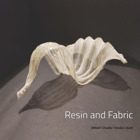
Resin and Fabric Althaf | Charlie | Tendai | Amit
Abstract The design of the proposed model came from the reaction of resin on fabric. This form was achieved by applying resin stratigically on the stretched fabric. After the study of many results a desirable form was achieved. The forms formed were a direct result of the reaction and could be predicted to a certain extent. The resin formed a wave-like pattern at certain junctions throughout the fabric. We later sewed metallic wires as exoskeleton to make a more defined form structurally and otherwise. The final form was a result of many evolutions and study of previous forms. The inferences of the experiment were to learn the way fabric reacted to the resin.
Contents Chapter 1 PROCEDURE
Chapter 2 EXPERIMENTS EXPERIMENT 1 EXPERIMENT 2 EXPERIMENT 3 EXPERIMENT 4 EXPERIMENT 5 EXPERIMENT 6 EXPERIMENT 7 FINAL FORM
Chapter 3 SITE ANALYSIS Chapter 4 ANALYSIS
ITERATIONS RADIATION ANALYSIS DAYLIGHT ANALYSIS
Chapter 5 CONCLUSION
Chapter 1 PROCEDURE
Procedure Step 1 A frame size of 25X30 cm was built as a main frame for our experiment. Step 2 Various sizes of fabric was used as the main model element. Step 3 Grids patterns were drawn on the fabric.
Step 4 The fabric was stretched over the frame and pinned on the edges.
Step 5 Resin and hardener in the ratio of 1:1 were applied on the fabric to form various patterns over the grids. This was left to dry for 5 hours.
Step 6 The fabric then was released from the frame, which then went on to give us various forms from various patterns.
Chapter 2 EXPERIMENTS
Experiment 1 Fabric size:
Before stretching After stretching Constant: Grid size 1x1 cm
A 22x24 22x33
B 22x24 22x33
C 17x30 22x33
5 hrs
D 17x30 22x33
E 17x30 22x33
F 15x25 22x33
Various sizes of fabric was used to find the optimum stretch required to form a doubly curved surface. The resin was applied in simple repetitive patterns to easily study the reaction and deformation the resin would cause on the fabric. Pattern A
B grids
resin with brush size 4
Top View
Side View
Pattern
Top View
Side View
C
D
E
F Inference: The resultant form obtained from the above experiment was close to fabric.
doubly curved surface in the
Experiment 2 Fabric size: Before stretching After stretching Constant: Grid size 1x1 cm
15x20cm and 15x25cm 22x23cm 5 hrs
In experiment two the optimum size of fabric was found to be 15X20. This size cause the fabric to stretch over the frame enough so as to no cause a trae on the fabric. The resin was applied in simple patters to see the deformation the resin lines cause on the fabric. Pattern
grids
Top View
resin with brush size 4
Isometric
Pattern
Top View
Side View
Inference: The extra stretch on the fabric gave the resultant doubly curved more volume and made the resultant more important.
Experiment 3 Fabric size: Before stretching After stretching Constant Grid Size 1X1 cm
15x20cm 22x23cm
5 hrs
In the third experiment the patters used were more complex so as to understand the study its results. These patters had perpendicular or tangential intersecting points. The resin applied here were also dense. Pattern
grids
resin with brush size 4
Top View
Isometric
Pattern
Top View
Isometric
Inference:1. The fabric size of 15x20 were found to produce the best results on a framework of 20x30.
2. The stretch of each of the fabric was done just enough so as to not produce a tear on the fabric .
Experiment 4 60 cm
Fabric size: 45x60cm
Constant: Grid size 3x3 cm
90 cm
5 hrs
In this experiment two sets of fabric were taken, each with the same dimension of 45X60cms’ over a frame of 90X60 cms’. The experiment were conducted keeping the same proportion and patterns as that of the previous experiments. Two brush sizes were used to apply resin, four and eight.
The original pattern
grids
resin with brush size 4
The resultant form of the original pattern
resin with brush size 8
Pattern
Top view
Isometric
Results:
1. In the experiment with the thicker brush size the form formed distinctive crest and trough. The brush size was taken with the exact proportions as the fabric and frame.
2. In the experiment with the smaller brush size the crest and rough were not distinguishable and did not form a proper wave. The brush size was not taken as an exact proportion as that of the fabric and the frame.
3. The resultant forms had wave that did not rise above a certain limit. This may have been due to the stretch of the fabric, it’s weight, the strength of the resin or all of the factors. Hence, these forms are not scalable.
Inference:
The form achieved as a resultant of this experiment is similar to that of the previous result. However the older form could not be replicated onto a larger scale as other factors such as density of the resin applied on the fabric to the ratio of the fabric itself differs.
Experiment 5 Fabric size:
Before stretching After stretching Constant: Grid Size 1X1 cm
15x20cm 22x23cm
5hrs
The fifth experiment was conducted with the fabric size of 15X20 cm over a frame of 20X30cm. In this experiment the forms were given edge conditions. These conditions were structural systems made of wires that went along the edges of the form. The wires were only added to the form after the resin has dried and were taken out of the frame.
Pattern
grids
resin
View 1
wire
View 2
Pattern
View 1
Inference: 1. The fabric size of 15X20 was used in this experiment.
2. An addition of an new element was made to provide an exoskeleton to the form. 3. This addition gave the result more volume and definition. 4. The exoskeleton also gave the form structural support.
View 2
Experiment 6 Fabric size: Before stretching After stretching Constant Grid Size 1X1 cm
15x20cm 22x23cm
5hrs
The forms in this experiment was a result of a structural system that went throughout the fabric. The wires were woven into the fabric in a pattern which was then followed by resin. There were two types of structural system that were used, wire and OHP sheets, the wires was used for its malleability and the OHP sheets were used for its flexibility. Pattern
grids
resin
View 1
wire
View 2
Inference: 1.
6.3
Pattern
View 1
View 2
The introduction of wires as a new structural system on the fabric gave it a definite shape. 2. The forms had more definition and volume.
Experiment 7
Pattern
Inference:
Inference:
grids
View 1
View 2
The wires were woven into the fabric in a rectangular pattern towards the centre. The form obtained was rigid.
The wires were woven to form a rigid pattern. The edge conditions that were given formed definitive curves. The wires woven within the fabric curved along with it.
resin
wire
Inference: The focal point on the edge of the fabric was chosen and the wires were woven . The radial lines curved with
the fabric and merged into the focal point. The wires used had a structural and definitive role in the formation of the curve.
Inference:
grids
1. The forms obtained were of definite shape. 2. The forms were more rigid. 3. The wires could be manipulated to give a more reasonable form.
resin
wire
F I N A L F O R M
FORM ON A SITE IN MURCIA, SPAIN
Chapter 3 SITE ANALYSIS
LOCATION - Museum of the University of Murcia
Temperature analysis
Solar analysis
Rainfall analysis
This plaza is surrounded by school and museum which makes this a prime location as an exhibition space. This plaza is less active as compared to the other plazas and therefore provides an optimum situation for exhibitions that gather people.
The form which is centrally located in the plaza will act as a temporary exhibition space or a stop at the center of the courtyard. The site was primarily chosen due to the context which it provided to the final form. An modernistic form amidst traditional buildings. The pavilion provides a much needed relief against the stoic facade.
Chapter 4 ANALYSIS
I T E R A T I O N S
Iteration one with 90 degrees
Iteration two with 70 degrees
Iteration three with 55 degrees
The original pattern was used to make the first model. The result from the analysis was that which already fulfilled the conditions we had set for the site analysis. The original iteration has an angle of 90 degrees between the resin lines.
Since the first pattern (original) fufilld the needs of the form, the aim of the pattern was to reduce the extreme radiation and sunlight of the southern side. The second iteration has an angle of 70 degrees between the resin lines.
The third pattern was also similar to that of the second pattern. The idea of it was to see how much of the extremity could be reduced. However, this created deformity in the model and therefore was discarded. The third iteration has an angle of 55 degrees between the resin lines.
ITERATION 1
ITERATION 2
ITERATION 3
SUMMER RADIATION ANALYSIS
AVERAGE RADIATION 0.004532
AVERAGE RADIATION 0.004729
AVERAGE RADIATION 0.004994
ITERATION 1
ITERATION 2
ITERATION 3
WINTER RADIATION ANALYSIS
AVERAGE RADIATION 0.00255
AVERAGE RADIATION 0.002542
AVERAGE RADIATION 0.002651
ITERATION 1
ITERATION 2
ITERATION 3
SUMMER DAYLIGHT ANALYSIS
DAYLIGHT HOURS : 0.011721
DAYLIGHT HOURS : 0.012141
DAYLIGHT HOURS : 0.012599
ITERATION 1
ITERATION 2
ITERATION 3
WINTER DAYLIGHT ANALYSIS
DAYLIGHT HOURS : 0.013187
DAYLIGHT HOURS : 0.013228
DAYLIGHT HOURS : 0.013331
TOP VIEW
FRONT ELEVATION
SIDE ELEVATION
SIDE ELEVATION
CONCLUSION The experiments were conducted as a form finding excercise. 2D impregnated patterns resulted in the formation of a continuous three dimensional surface with variable stiffness. Reaction of resin on stretched fabric gave a form that totally was not predictable. But we could manipulate the resultant form to a certain extent by studying the results and inferences from the earlier experiments. To further control the results, wires were used as edge conditions which gave the form a clear height. Later on in the experiments exoskeleton like structures were used to give a more stable and definite form. The resultant form obtained from these experiments were even more controllable and can be manipulated easily with the patterns used.
FURTHER DEVELOPMENT The system developed can be used as a design approach that could be scaled up for architectural applications. The forms attained can be used as facades, louvers even a pavilion or other functional buildings. Unlike form making, this is clearly a form finding approach since we dont know what the resultant form will be definitely. The scalability of the form need not correlate with that of the material. The material properties would change according to the scale. So the forms could be built using other materials like steel, glass, carbon-fiber etc. The pavilion we suggested was build as a steel structure with a mesh over. LED lights could be embedded on the exoskeleton to give a active feel during the nights.
School of Architecture and Planning Sharda University