14 minute read
Field-programmable gate array-based field-oriented control for permanent magnet synchronous motor drive

from Field-programmable gate array-based field-oriented control for permanent magnet synchronous motor dr
Nam Duong Le1,2, Le Quang Linh1 , Nguyen Tien Huy Cong1, Phuong Vu1 , Tung Lam Nguyen1
1School of Electrical Engineering, Hanoi University of Science and Technology, Hanoi, Vietnam
Advertisement
2Faculty of Engineering and Technology, Quy Nhon University, Binh Dinh, Vietnam
Article Info
Article history:
Received Mar 11, 2022
Revised Jun 28, 2022
Accepted Aug 11, 2022
Keywords:
Field programmable gate array
High power density
PMSM drives
Three phase inverters
ABSTRACT
Permanent magnet synchronous motor (PMSM) is a special type of synchronous electric motor that has many applications such as in the manufacturing industry of robots, self-propelled mechanisms, in the medical fiel. In this paper, the permanent magnet synchronous motor motor control structure according to the field-oriented control (FOC) algorithm will be implemented on the field-programmable gate array (FPGA) card. Function blocks in FOC algorithm for example PI controller, space vector pulse width modulation (SVPWM) algorithm will be integrated into individual itegrated circuit (Ics) then will be connected to form an IC with the function of implementing FOC algorithm. Furthermore, this algorithm will be used for powertrains using gallium nitride (GaN). GaN technology provides switching frequencies up to 100 kHz instead of the upper 2 to 20 kHz like insulated gate bipolar transistor (IGBT) transistors. With GaN technology, it is possible to reduce switching losses as well as increase the efficiency of the power converter. The performance results will be verified through the typhoon hardware in the loop (HIL) device.
This is an open access article under the CC BY-SA license.
Corresponding Author:
Phuong Vu
School of Electrical Engineering, Hanoi University of Science and Technology
No. 1, Dai Co Viet Road, Hai Ba Trung, Hanoi, Vietnam
Email: phuong.vuhoang@hust.edu.vn
1. INTRODUCTION
Permanent magnet synchronous motor (PMSM) has outstanding advantages: very high efficiency up to 97.5%, the rotor speed is equal to stator magnetic field speed, so it is very stable and accurate in all adjustment areas speed. Many algorithms have been developed to improve control quality [1]. Besides, materials science is developing strongly, including research direction on high power density in the field of power electronics. Not only meet the power but also ensure the size in many applications example electric vehicles, airplanes [2]. Semiconductor technology using gallium nitride (GaN) material that allows switching with frequencies from 50 Hz to 200 Hz instead of 2 to 20 kHz in insulated gate bipolar transistor (IGBT) transistors [3]. Besides, GaN technology also allows operation at high temperatures and reduces switching losses. The efficiency of GaN technology is practically proven in DC/DC converters [4] or 3-phase voltage source inverters (VSI) [5]. However, to be compatible with large switching frequencies, the computing power of the microcontroller must be compatible. For example, in motor control if the switching frequency is 100 kHz, the current loop control must also be sampled at the corresponding 100 kHz, so the calculating time should be less than 10 μs. With a high sampling frequency, the microcontroller’s resources will be limited since with a microcontroller we cannot perform many functions, and the control loops are limited [6] Field-programmable gate array (FPGA) technology [7] provides multithreading capabilities, allowing high-frequency sampling [8] would be the appropriate choice. Furthermore, FPGA manufacturers also provide a system-on-chip (SoC)
Journal homepage: http://telkomnika.uad.ac.id environment useful for designers to synthesize, collect, and verify results [9]–[17], so FPGA technology is currently being widely used in transmission and power electronics.
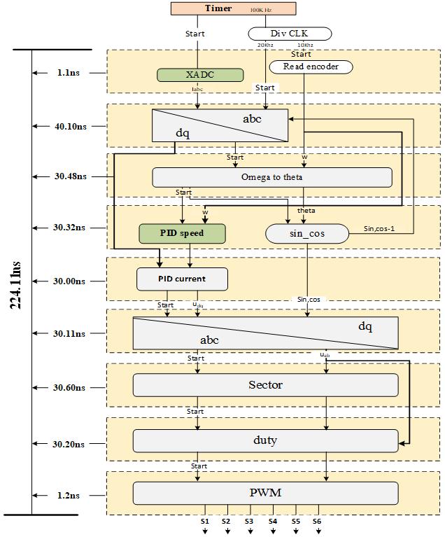
In this paper, the field-oriented control (FOC) algorithm will be implemented manually using the very high speed integrated circuit (VHSIC) hardware description language (VHDL) language on the Xilinx Zybo Zynq 7010 FPGA platform. Manual implementation of the algorithm helps us to understand the architecture of the FPGA and to be able to reuse the function block capabilities in other studies. They will be described in the next section. Figure 1 depicts the structure of the FOC algorithm that will be implemented in this work.
2. IMPLEMENTING FOC ALGORITHM ON FPGA
This section will present in detail the FOC algorithm to control the PMSM motor. The component blocks in Figure 1 correspond to a library packaged (IP) or an integrated circuit (IC). All these IP can be reused in other projects. We refer to [15]–[25] paper for algorithm implementation.
2.1. FOC algorithm and modeling the permanent magnet synchronous motors
The three-phase AC motor has a complex structure, and it has caused considerable difficulty in the mathematical description of the isolation characteristics that can be used to independently control the two flux-generating current components (excitation circuit current) and torque generating a current (armature circuit current). The field-oriented control provides a tool that allows separating the flux-generating current (������) and torque-generating current (������) components from the 3-phase alternating current flowing in the stator windings of the motor ( ������,������,������ ). The drive system controlled by the FOC method is a system that operates on the principle of isolating the above current components using a stator current regulating loop.
The (1), (2), (3), (4) are the equations describing the dynamics of the pmsm motor on the rotation coordinate system ����. Through these equations, we can calculate the parameters for the current controller and the speed controller
Assume the parameters of the induction motor are stator resistance ����, magnetic flux ���� number of pairs pole
, axial and transverse inductance ������,������, synchronous speed, electric speed ����
Field-programmable gate array - based field-oriented control for permanent magnet (Nam Duong Le)
2.2. Measurement of feedback current by XADC in FPGA XADC is an analog-to-digital converters (ADC) module integrated into the Xilinx FPGA series. XADC includes 2 channels of 12bit ADC, a built-in sensor, and 1 megasamples per second (MSPS) sampling rate. In this topic, we will use XADC to measure the stator current of the motor, so we will use analog input measurement pins to perform the measurement. XADC is a 2-channel ADC, measuring the voltage difference between 2 pins P and N to convert data. It has 2 operating modes, unipolar measurement mode, and bipolar measurement mode.
In this article, we will use the unipolar mode of ADC In unipolar mode, XADC has a measuring range from 0 to 1V. Converts to the corresponding value from 000h to FFFh without accents. If the potential difference between the two terminals P and N is less than 0V, the conversion value is 000h, or greater than 1V, the conversion value is FFFh. Since the ADC is 12 bit wide, 1 least significant bit (LSB) will correspond to 1/4095 ≈ 0.244e-3 V = 0.244 uV. To measure the current by XADC, we convert the stator phase current into a voltage according to the (5). ��(��)=001⋅��(��)+05
(5)
Where I is the instantaneous value at the time of measurement (A), U is the voltage value applied to the XADC. From (5) we see the input voltage to XADC will be in the range of 0 to 1V. Since 1 LSB of XADC corresponds to 0.244uV, we will calculate the measurement limit in this case.
2.3. Measurement the feedback speed of PMSM
To measure the motor speed, we use the Incremental encoder to output pulses on two channels a and b. The pulses on 2 channels will be transmitted to the digital input pin of the FPGA, where we will perform computational programming to calculate the motor speed. If you do it the same way, surely the reading speed value will be wrong. The closer the encoder is to the motor, the more noise, the larger the motor power, the more noise. Therefore, it is necessary to prevent interference by both hardware and software.
In this paper, I read the encode pulse value at 4 different times t1, t2, t3, t4 through which we can know whether the motor is rotating forward or backward in Figure 2. To calculate motor speed, we count the encodercount in a constant time. At this time, the encodercount variable will be equivalent to the rotation angle of the motor, dividing this value with the predetermined time will get the speed of the motor. In this application, we will perform rate sampling with a frequency of 2000 Hz. Since the clock frequency is 1 MHz, we will use a counter to count every time the counter counts up to the value 500, we multiply the encodercount variable by a constant to get the motor speed.
Assume that when the variable counter is overflow, encodercount’s value is ��, the number of pole pairs is ����, encoder has �� pulses per revolution (PPR), the electrical rotor speed is calculated (6). Set the values of ����, �� depending on the parameter of motor and encoder.

2.4. Coordinate system conversion
According to Figure 1, the speed controller creates input for ��-axis current controller and the input of the ��-axis controller is zero by default. These inputs will be compared with the responses from the current sensor which was converted through clark transformation and park transformation (known as alpha-beta transformation and ���� transformation respectively). The output of these controllers, which is in ���� frame will be transformed to ���� frame through ���� to ���� transformation and then feed the SVM module. The following Table 1 show details about ���� and ���� transformation
To deploy the ���� and ���� transformation module in the FPGA card the (7) to (12) equations is introduced. The trigonometric functions ������(��) and ������(��) will be determined by using the look-up-table method. All this data will be moved to transformation module, from there can significantly reduce processing time because retrieving a value from memory is often faster than carrying out a computation.
2.5.
PI controller is very popular in the industry. This kind of controller is supposed the most effective controller for motor control. In this paper, PI controller will be used for both speed and current controller. The speed controller generates the stator current reference ������ ∗ ( ������ ∗ is zero by default), the outputs of current controllers are stator voltage Usd and Usq, which become the input of the digital SVPWM module. The PI controller is described in a differential as in (13)
Where ���� is the proportional gain, ���� is the integral time constant, ��(��) is the error (different bettwen reference and feedback) and ��(��) is the control signal of the controller. The (13) illustrates a continous PI controller so to implement it on FPGA platform, a discrete one is needed. With the sample period ��, the (13) also can become a difference equation by discretization as:
The (14) illustrate a digital PI, it can be used for any digital controller, so is FPGA. Nevertheless, because of discretization with sampling time �� so the quality of control will deplete. To reduce this effect, the smaller the sampling time is, the more effect is eliminated, �� so the anti-windup is added to reduce the overshooting problem when saturation = ‘1’, the controller is in saturation condition, the integral component is removed top prevent control signal from overshoot.
Saturation flag to control the anti-windup component.
When saturation = ‘0’, the controller is not in saturation condition and work as a normal PI controller
2.7. Space vector PWM technique
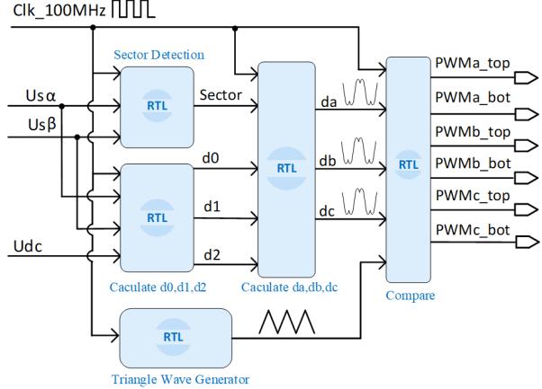
Space vector modulation (SVM) is a technique used for pulse width modulation (PWM); it is commonly applied for voltage source inverter (VSI). The biggest advantage of this technique is that it can utilize up to 1 √3 time of DC side voltage (≈ 0.577 ������) compared to only 0.5 ������ of the Sin PWM technique. In this research, it will be programmed to generate the gate pulse at frequency 100 kHz for 2-level VSI using GaN devices. The SVM algorithm divides the space vector on the stationary ���� frame into 6 sectors by the basic vectors ��1 to ��6 shown in Figure 3, moreover, there are also two zero-vectors ��0 and ��7
Any voltage-vector in the ���� frame belongs to one of these six sectors and can be synthesized from two adjacent basic vectors and two zero vectors. For example, with vector �� in Figure 3, it is the result of the synthesis from ��1, ��2, and zero-vector according to the relation: �� =��1��1 +��2��2 +��0��0/7 (15). Where ��0, ��1, ��2 is the duty-ratio of each vector, which is determined by the (16), (17)
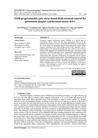
Where ���� is a 2×2 matrix that depends on the sector as shown in Table 2. The duty ratio after being determined will be used to calculate ����, ����, ���� using the formula in Table 3, which is the duty cycle of the high side switch in the voltage source inverter. When finishing the calculation, they will be compared with triangle carrier waveform at frequency 100 kHz to generate the gate pulse to high-side switch, low-side switch gate pulse is the inverse of the high-side switch gate pulse. From the theory and equations presented above, the SVPWM technique is programmed on the FPGA platform, Figure 4 shows the block diagram of its implementation in this research. Each block is equivalent to an register-transfer level (RTL) module in FPGA design and connected by the interconnect wires.
3. RESULTS AND DISCUSSION
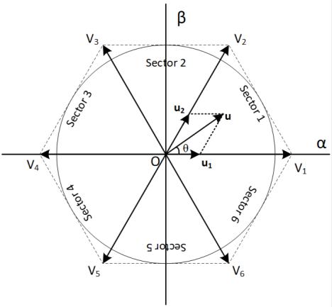
This section shows some test results with hardware in the loop (HIL) storm to show the validity of the study. FPGA and HIL storm connectiondiagram is shown in Figure 5, experimental model is given inFigure 6 and parameters are givenin Table 4 and Table 5. Figure 6 presents the structural diagramof HIL experimental system.

3.1. Resource usage and processing time
Where we see that the calculation speed of the FPGA is quite fast 0.22 µs while the sampling period is 10 µs as shown in Figure 7 from there we can use the calculation results for other purposes instead of waiting for the next period. resources used the account for 1/3 >1/2 of the total resources of the FPGA shown in Table 6. Thus, designer can choose the appropriate allocation and the corresponding scheduling which fit the best his application.
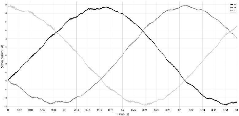
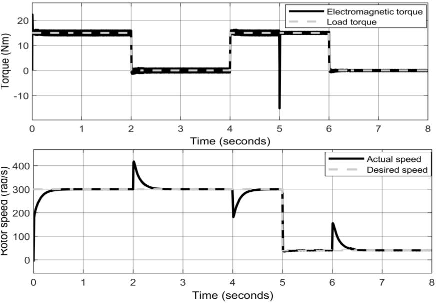
3.2. Result when launching with typhoon HIL devices
This section will show the three-phase stator current response of pmsm motor when load is Nm, there by showing the efficiency of FOC algorithm when implemented on fpga card. The sinusoidal stator current response evaluation of FOC control structures at speed of 280 rad/s are expressed through Figure 8(a), Figure 9(a) and Figure 8(b), Figure 9(b) with speed of 30 rad/s when variable load. Figure 10 shows the appropriate speed and torque response to the requirements. The amplitude, frequency of the current and the motor speed are in full agreement withthe theory
Field-programmable gate array - based field-oriented control for permanent magnet (Nam Duong Le)


4. CONCLUSION
The implementation of a vector control algorithm using FPGA for permanent magnet synchronous motor drive was successfully developed by manual coding method in this contribution. PMSM motor can operate in a wide speed range with a single parameter of PI controller. The results in the paper show the effectiveness of FPGA cards in power electronics applications. Shows that it is possible to integrate an algorithm into a dedicated IC and we can reuse this integrated IC in many different cases. In some cases, FPGA cards can completely replace current microcontrollers to increase the system’s performance in computing.
Acknowledgements
This research is funded by the ministry of education and training (Vietnam) under project number CT2020.02.BKA-06.
References
[1] M. S. Rafaq and J. -W. Jung, “A comprehensive review of state-of-the-art parameter estimation techniques for permanent magnet synchronous motors in wide speed range,” IEEE Transactions on Industrial Informatics, vol. 16, no. 7, pp. 4747–4758, 2020, doi: 10.1109/TII.2019.2944413.
[2] R. Lai et al., “A high-power-density converter,” IEEE Industrial Electronics Magazine, vol. 4, no. 4, pp. 4–12, 2010, doi: 10.1109/MIE.2010.938722.
[3] K. Shirabe et al., “Efficiency comparison between si-IGBT-based drive and GaN-based drive,” IEEE Transactions on Industry Applications, vol. 50, no. 1, pp. 566–572, 2014, doi: 10.1109/TIA.2013.2290812.
[4] F. Canales, P. Barbosa, C. Aguilar, and F. C. Lee, “A high-power-density DC/DC converter for high-power distributed power systems,” in IEEE 34th Annual Conference on Power Electronics Specialist, 2003. PESC ’03., 2003, vol. 1, pp. 11–18, doi: 10.1109/PESC.2003.1218267.
[5] H. Li et al., “Design of a 10 kW GaN-based high power density three-phase inverter,” in 2016 IEEE Energy Conversion Congress and Exposition (ECCE), 2016, pp. 1–8, doi: 10.1109/ECCE.2016.7855019.
[6] A. O. Rait and P. Bhosale, “FPGA implementation of space vector PWM for speed control of 3-phase induction motor,” in 2011 International Conference on Recent Advancements in Electrical, Electronics and Control Engineering, 2011, pp. 221–225, doi: 10.1109/ICONRAEeCE.2011.6129782.
[7] J. J. R -Andina, M. J. Moure, and M. D. Valdes, “Features, design tools, and application domains of FPGAs,” IEEE Transactions on Industrial Electronics, vol. 54, no. 4, pp. 1810–1823, 2007, doi: 10.1109/TIE.2007.898279.
[8] R. Joost and R. Salomon, “Advantages of FPGA-based multiprocessor systems in industrial applications,” in 31st Annual Conference of IEEE Industrial Electronics Society, 2005. IECON 2005., 2005, doi: 10.1109/IECON.2005.1568946.
[9] J. L. Bastos, H. P. Figueroa, and A. Monti, “FPGA implementation of neural network-based controllers for power electronics applications,” in Twenty-First Annual IEEE Applied Power Electronics Conference and Exposition, 2006. APEC ’06., 2006, doi: 10.1109/APEC.2006.1620729.
[10] E. T. Mekonnen, J. Katcha, and M. Parker, “An FPGA-based digital control development method for power electronics,” in IECON 2012 -38th AnnualConference on IEEE Industrial ElectronicsSociety, 2012, pp. 222–226, doi: 10.1109/IECON.2012.6388804.
[11] P. Le-Huy, S. Guerette, L. A. Dessaint, and H. Le-Huy, “Real-Timesimulation of power electronics in power systems using an FPGA,” in 2006CanadianConferenceonElectricalandComputerEngineering,2006,pp.873–877,doi:10.1109/CCECE.2006.277356.
[12] E. Monmasson, L. Idkhajine, I. Bahri, M. -W. -Naouar, and L. Charaabi, “Design methodology and FPGA-based controllers for power electronics and drive applications,” in 2010 5th IEEE Conference on Industrial Electronics and Applications, 2010, pp. 2328–2338, doi:10.1109/ICIEA.2010.5515585.
[13] M. V Chung, D. T. Anh, and P. Vu, “A finite set-model predictive control based on FPGA flatform for eleven-level cascaded H-Bridge inverter fed induction motor drive,” International Journal of Power Electronicsand Drive Systems (IJPEDS), vol. 12, no. 2, pp. 845-857, 2021,doi:10.11591/ijpeds.v12.i2.pp845-857.
[14] W Zhao, B H Kim, A. C. Larson, and R. M. Voyles, “FPGA implementation of closed-loop control system for small-scale robot,” in ICAR ’05. Proceedings., 12th International Conference on Advanced Robotics, 2005., 2005, pp. 70
77, doi: 10.1109/ICAR.2005.1507393.
[15] T. D. Do, N. D Le, V. H. Phuong, and N. T. Lam, “Implementation of FOC algorithm using FPGA for GaN-based three phase induction motordrive,” BulletinofElectricalEngineeringandInformatics,vol.11,no.2, pp.636–645,2022,doi:10.11591/eei.v11i2.3569.
[16] Y -S. Kung, C -S. Chen, K -I Wong, and M -H. Tsai, “Development of a FPGA-based Control IC for PMSM Drive with Adaptive Fuzzy Control,” 31st Annual Conference of IEEE Industrial Electronics Society, 2005 IECON 2005., 2005, doi: 10.1109/IECON.2005.1569134
[17]
Q. B. Dang, N. D. Ngoc, V. H. Phuong, and M. C. Ta, “Implementation of frequency-approach-based energy management for EVs using typhoon HIL402,” in 2019 IEEE Vehicle Power and Propulsion Conference (VPPC), 2019, pp. 1–6, doi: 10.1109/VPPC46532.2019.8952271.
[18] V T Ha, V H Phuong, N T Lam, and N P Quang, “A dead-beat current controller based wind turbine emulator,” in 2017 International Conference on System Science and Engineering (ICSSE), 2017, pp. 169–174, doi: 10.1109/ICSSE.2017.8030859.
[19] L. N. Duong, V. H Phuong, N. V Lien, and T. T Minh, “A modified deadbeat current controller for field oriented induction motor drivers,” in 2021 International Conference on System Science and Engineering (ICSSE), 2021, pp. 241–245, doi: 10.1109/ICSSE52999.2021.9538495.
[20] A. M. Eltamaly, “FPGA based speed control of three-phase induction motor using stator voltage regulator,” Mansoura Engineering Journal, vol. 32, no. 2, pp. 93–100, 2020. [Online]. Available: https://www.researchgate.net/publication/236645340_FPGA_Based_Speed_Control_of_Three-Phase_Induction_Motor_Using_ Stator_Voltage_Regulator
[21] M. Sulaiman, F. A. Patakor, and Z. Ibrahim, “DSP based implementation of field oriented control of three-phase induction motor drives,” International Journal of Research in Engineering and Technology, vol. 02, no. 09, pp. 179–186, 2013, doi: 10.15623/ijret.2013.0209027.
[22] J. Bocker and S. Mathapati, “State of the art of induction motor control,” in 2007 IEEE International Electric Machines & Drives Conference, 2007, pp. 1459–1464, doi: 10.1109/IEMDC.2007.383643.
[23] V. Vlatkovic and D. Borojevic, “Digital-signal-processor-based control of three-phase space vector modulated converters,” IEEE Transactions on Industrial Electronics, vol. 41, no. 3, pp. 326–332, 1994, doi: 10.1109/41.293903.
[24] M. Marufuzzaman, M. B. I. Reaz, and M. A. M. Ali, “FPGA implementation of an intelligent current dq PI controller for FOC PMSM drive,” in 2010 International Conference on Computer Applications and Industrial Electronics, 2010, pp. 602
605, doi: 10.1109/ICCAIE.2010.5735005.
[25] M. A. Bevilaqua, A. Nied, and J. de Oliveira, “Labview FPGA FOC implementation for synchronous permanent magnet motor speed control,” in 2014 11th IEEE/IAS International Conference on Industry Applications, 2014, pp. 1–8, doi: 10.1109/INDUSCON.2014.7059427.
Biographies Of Authors
Nam Duong Le received a master's degree in Electronic Engineering from the University of Danang in 2011. Since 2004 he has been a lecturer at the Faculty of Engineering and Technology, Quy Nhon University. Currently, he is a PhD student at the Institute of Engineering and Automation - Hanoi University of Science and Technology. His research interests include electrical machine drive, Power electronics, electric vehicles, FPGA. He can be contacted at email: lenamduong@qnu.edu.vn.
Le Quang Linh is currently a student at Hanoi University of Science and Technology. His major at Hanoi University of Science and Technology is Control Engineering and Automation and will complete his course in 2021. His research interests include power electronics, electric vehicles, electrical machine drive, FPGA. He can be contacted at email: linh.lq174016@sis.hust.edu.vn.