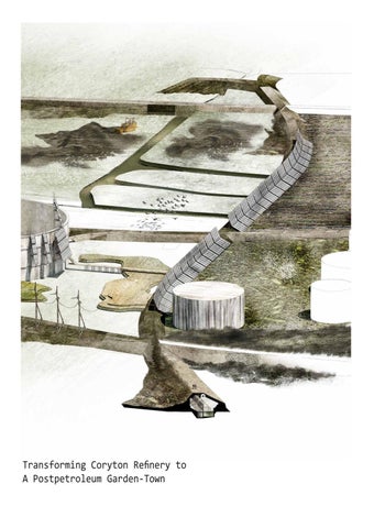
Transforming Coryton Refinery to A Postpetroleum Garden-Town
Problematising Petro-culture Oil/ Architecture of Subtraction and Excavation/Fissure and Fragments
London
Coryton Refinery-Aerial View
Coryton Refinery
Coryton Refinery: Ruins of a Petro-Structures
Reclaimation of the Oil Landscape by Nature/ Remediation and Rehabilitation
Sublime Spaces of Oil Culture/Urbanisation, Degradation
Post-Industrial Architectural Ruins-Reclaiming by Nature
Remediating Contaminated Lands through Natural Processes
Sequential Zones for Revitalisation of Soil-Gardening
Decontamination as A Performance
1-SOIL REMEDIATION 2-WATER REMEDIATION 3-AIR REMEDIATION 4-COURTS OF POLICY R5-ETURN TO THE NATURE
1
5
4 3
2
Lake-Canal-Wood-Walls
Earth works and Water works Strategies
Remediation Reactor Soil Bioremediation
Remediation Reactor Water Treatment
Solid-phase soil reactor or land-farming system: The soil is excavated, mixed with nutrients and microorganisms and evenly spread out on a linear. with regular ploughing to favour mixing and aeration, mineralisation of petroleum hydrocarbons present at initial concentrations of tens of g kgfollows first kinetics with a half-life of ca 2 years. Lndfarming is an established technique for the remediation of hydrocarbon-contaminated soil.
Soil remediation-Water Treatment/ Architecture of canals and containers
Courts of Earth Remediation/ Studies and Operation
Courts of Earth Experimentation and Living
Courts of Water Experimentation and Living
Recovering the Lost Grassland
Integrating Phytoremediation with Landscape restoration and Garden design Biological Laboratory and field pilot study
Morphology of natural_architectural reclaimation/Swell ans Swallow
Architectural study for Ecological Parasites
1
3
2 4
Developement Phasing/ Tank Typologies
Algae Bioreactor/ Alternative to Petroleum
Tank Introverted Architecture
Subterranean Links between Berms and Tanks
A small-scale biogas reactor or anaerobic digester is an anaerobic treatment technology that produces (a) a digested slurry (digestate) that can be used as a fertilizer and (b) biogas that can be used for energy. Biogas is a mix of methane, carbon dioxide and other trace gases which can be converted to heat, electricity or light. Small-scale biogas reactors are typically designed to produce biogas at the household or community level in rural areas. The airtight reactors are filled with animal manure from the farm. Kitchen and garden wastes can also be added and toilets can directly be linked to the reactor for co-treatment of excreta.
Isolated wind–photovoltaic hybrid power system with battery storage
Scandinavia Is Home To Heavy-Duty Electric Construction Equipment & Truck Development: Pon Equipment, in association with Caterpillar, has developed a zero emissions 25 inch (63.5 cm) electric excavator called the 323F that will be sold as part of the company’s Z Line of zero emissions earth moving and construction equipment. The machine can operate for up to 7 hours on a single battery charge.
Hybrid energy systems can be defined as energy systems in which two or more energy sources are used together to generate electric power. In hybrid energy systems, a few electricity generation elements are brought together to meet the electric power demand of a plant, rural house, or urban house at a short or long distance from the electric grid. Electricity for the general illumination and pumps is generated through a battery-reinforced hybrid wind– solar power generation system.
https://sswm.info/arctic-wash/module-4-technology/ further-reseources-wastewater-treatment/anaerobicdigestion28%-small-scale29%
Alternative Power generators/ Renewables
Earth works/ Subterranean connections
Soil borrow pit
Earth work- An Architecture of Dig and Fill
Berms modulation and construction with reclaimed site materials
Constructing Berms/Material Reuse
Borehole might be use to assist tree establishment
Year
Farming Field
1
2
WOODLAND SQUARE, Tree growth as the indication of land decontamination
3
4
More than 2000 trees, a combination of hybrid poplar and willow will be planted through a collective conduct in an ordered grid with the spacing of 6x7 meter to keep and counteract the former industrial trace of the site
Vapor Extraction and Control 500
Phytocap
Field evidence- Made Ground (ERM, 2018)
Clean Soil
0
No obvious visual/olfactory evidence of impact noted in soil Hydrocarbon taining (only) noted in soil)
Hydrocarbon odour (only) noted in soil Hydrocarbon staining and odour noted in soil
Contaminated Soil+TPH degrading consortia
Leachate Collection and Treatment
Perforated Pipes
Impermeable Base
Ecopile Typology
0
500
Groundwater monitoring well
TPH Concentration (Aliphatics/Aromatics>Cs-C44) Sample type (ERM, 2018) Below detection limit Deep Borehole
BH
< 1000 μg/m Shallow Borehole
1000-5000 μg/m SH
Shallow Borehole
5000-10000 μg/m
>10000 μg/m
TP
Tilling for soil aeration
Contaminated soil
Bern
Leachate collection and treatment
0
500
Total VOC Contamination (ERM, 2018) Below detection limit
< 1000 μg/m
Contaminated soil 1000-5000 μg/m
5000-10000 μg/m
>10000 μg/m
Soil vapour monitoring probes Capping Air injection
Leachate collection and treatment
Treatment bed
Nutrient and moisture addition Capping liner
0
500
Contamination mapping superimposed by proposed water and woodland zones
Typical Biopile and Landfarming system (Brown, et al, 2017)
Mapping the site Contamination
Typologies for passive soil Remediation
Map 1: Potential sources of contaminants(ERM, 2018) Potential historic sources Significant impact noted Minor impact noted Contemporary sources Existing oil tanks
1- Historical overtopping of moat and surface drainage 2- Historical free product observed in shallow soils 3- Deep sumps for oily process water 4- PCE use 5- PCE use and PFOS fire 6- Bundle cleaning area 7- Badly cracked and heavily stained floor slab with sub-slab product 8- Historic process and solvent sumps 9- Former lead sludge pits 10- Additive tanks
C B
D
E
A F
Main Systems of Remediation and Transformation A- Thames River B- Central Water Basin C- Woodland Square
D-Farming Field E- Berms Network F- Clean water Basin
Central Basin
Water treatment canal
Contaminated water resulted from tank washing will be directed to the treatment basin by moats on the boundary
Water link to the Hole Haven
Water Gate
Contaminated water resulted from tank washing will be directed to the treatment basin by moats on the boundary
Input water from the Thames
Existing drainage network
Contaminated water moat
Clean water Basin
A building system for ongoing excavation, construction and living