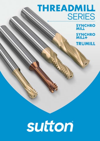
SERIES
Carbide Threadmills Solid Carbide Threadmills provide a highly controlled and repeatable method for producing internal and external threads in CNC machining environments. By utilisng circular interpolation, thread milling eliminates many of the limitations associated with traditional tapping while improving process stability, accuracy, and tool life in most materials.
Watch the video
Contents PAGE INDEX Thread Sutton Surface depth Designation Finish
2.5xDt
LH Cutting
TiAlSiN
3xDt
LH Cutting
ZrN
2xDt
RH Cutting
ZrN
2xDt
RH Cutting
ZrN
M
UNC
UNF UNEF
TM04
TM08
NPT
BSPF (G)
BSPT (Rc)
TM02 Page 4
TM01 Page 5
TM03 Page 6
Page 7
TM06
Page 8
Page 10
TM05 Page 9
TM07 Page 11
Features & Benefits
Thread milling from solid saves valuable production time by reducing the number of tools required to generate a quality thread. No longer do you need to drill before threading, complete the whole process with the one tool.
Deep thread quality is improved through left-hand cutting geometry and through-tool coolant. Together with reduced cutting length engagement, these features minimise vibration, enhance process stability, and extend tool life by efficiently evacuating chips from the cutting zone.
Helical flute threadmills optimise chip formation and evacuation, delivering more stable cutting conditions, improved thread quality, and extended tool life with through-tool coolant chip evacuation.
2
Success Stories TM02 0800 fz (mm/tooth)
Vc (m/min)
Tool Life
0.015 30 30 128 threads 48 threads Competitor
Set up Work-piece Material Hole Type Thread Depth Coolant
0.022
44% 75% LESS COST
Injection Mould D2 / X155CrVMo 12-1 (1.2379) 60HRC Blind hole 18mm Dry (with air)
TIME*
SAVING*
TM01 0600 fz (mm/tooth)
Vc (m/min)
Tool Life
0.028 60 50 1680 threads 1020 threads Competitor
Set up Work-piece Material Hole Type Thread Depth Coolant
0.03
33% 40% LESS COST
Housing SS304 / SUS304 / X5CrNi18-10 / 1.4301 Blind hole 14mm Emulsion 7%
TIME*
SAVING*
TM03 1600 fz (mm/tooth)
Vc (m/min)
Tool Life
0.06 90 70 400 threads 300 threads Competitor
Set up Work-piece Material Hole Type Thread Depth Coolant
0.06
Housing AISI 4140 / 42CrMo4 / 1.7225 Blind hole 30mm Emulsion 10%
22% 35% LESS COST TIME*
SAVING*
* Results are based on controlled test conditions and may vary depending on application, materials, machine settings and operating environment.
3
Threadmills from Solid - Internal Metric, 2.5xDt , LH Cut • Special end face geometry to generate hole from solid • Left Hand Cutting, stabilises the tool • Universal geometry for wide range of materials • Depths up to 2.5 x Dt • For through & blind holes • Can be used in pre-drilled holes • Improve productivity with Drill / Mill technology • Suitable for both LH and RH threads
30°
A
Catalogue Code Product Group Material Surface Finish Sutton Designation Geometry Shank Form (DIN 1865)
l4
A
3
D1002 VHM TiAlSiN
UNI LH Cutting
Vc Page #: 12
Hole Dia Page #: 16
Size Ref.
Dt
Pitch
d1
l1
l2*
l3
l4
d2
z
Item #
M2.5 M3 M4 M5 M6 M8 M10 M12 M16
0.45 0.5 0.7 0.8 1 1.25 1.5 1.75 2
1.40
39
1.3
6.5
0.68
3.0
4
2.40
58
1.5
7.5
0.75
6.0
4
3.10
58
2.1
10.0
1.05
6.0
4
3.80
58
2.4
12.5
1.20
6.0
4
4.60
64
3
15.0
1.50
8.0
4
6.20
64
3.6
20.0
1.88
8.0
4
7.50
73
4.5
25.0
2.25
10.0
4
9.00
73
5.2
30.0
2.63
10.0
4
11.50
90
6
40.0
3.00
12.0
4
TM02 0250 TM02 0300 TM02 0400 TM02 0500 TM02 0600 TM02 0800 TM02 1000 TM02 1200 TM02 1600
P
ISO
TM02
1
2
3
4
5
6
7
M 8
9
10
11
K
N
S
H
12 13 14.1 14.2 14.3 15 16 17 18 19 20 21 22 23 24 25 26 27 28 29 30 31 32 33 34 35 36 37.1 37.2 37.3 37.4 37.5 38.1 38.2 39.1 39.2 40 41
• • • • • • • • • • • • • • • • • • • • • • • • • • • • • •
VDI 3323
HB
P Steel M Stainless Steel K Cast Iron N Non-Ferrous Metals S Titanium & Super Alloys H Hard Materials
D t = Nominal Thread Diameter * l 2 includes 1 x Pitch of partial thread
• • • • • • • • • • • • • • • • •
0250 0300 0400 0500 0600 0800 1000 1200 1600
4
TM02
• Optimal • Effective
Threadmills Internal Metric, 3xDt , LH Cut • Left Hand Cutting, stabilises the tool • With axial coolant 3mm & above • Universal geometry for wide range of materials • Depths up to 3 x Dt • For through & blind holes • Suitable for both LH and RH threads • Ideal for difficult to machine threads where taps typically break • Optimised cutting length to reduce vibration
Catalogue Code Product Group Material Surface Finish Sutton Designation Geometry Shank Form (DIN 1865)
3
TM01 D1002 VHM ZrN
UNI-IK LH Cutting
Vc Page #: 12
Hole Dia Page #: 16
Size Ref.
Pitch
d1
l1
l2
l3
d2
z
Item #
0.45 0.50 0.70 0.80 1.00 1.25 1.50 1.75 2.00 2.50
1.95
39
1.4
7.5
3.0
4
2.40
39
1.5
9.5
3.0
5
3.20
58
2.1
12.5
6.0
5
4.00
58
2.4
16.0
6.0
6
4.80
58
3.0
20.0
6.0
6
5.95
73
3.8
24.0
6.0
7
7.80
73
4.5
23.0
8.0
7
9.00
84
5.3
26.0
10.0
7
11.80
90
6.0
41.0
12.0
8
15.00
105
7.5
51.0
16.0
8
TM01 0250 TM01 0300 TM01 0400 TM01 0500 TM01 0600 TM01 0800 TM01 1000 TM01 1200 TM01 1600 TM01 2000
P
ISO
TM01
1
2
3
4
5
6
7
M 8
9
10
11
K
N
S
H
12 13 14.1 14.2 14.3 15 16 17 18 19 20 21 22 23 24 25 26 27 28 29 30 31 32 33 34 35 36 37.1 37.2 37.3 37.4 37.5 38.1 38.2 39.1 39.2 40 41
• • • • • • • • • • • • • • • • • • • • • • • • • • • • • •
VDI 3323
HA
P Steel M Stainless Steel K Cast Iron N Non-Ferrous Metals S Titanium & Super Alloys H Hard Materials
D t = Nominal Thread Diameter *Refer pages 16-19 for specific hole diameters
• • • • • • • • • • • • •
0250 0300 0400 0500 0600 0800 1000 1200 1600 2000
Dt M 2.5 M3 M4 M5 M6 M8 M 10 M 12 M 16 M 20
• Optimal • Effective
5
Threadmills Internal Metric, 2xDt • Right Hand Cutting with axial coolant • Depths up to 2 x Dt • For through & blind holes • Suitable for both LH and RH threads • Helical flutes to reduce load and improve stability • Improved productivity with longer cutting length
Catalogue Code Product Group Material Surface Finish Sutton Designation Geometry Shank Form (DIN 1865)
D1002 VHM ZrN
UNI-IK RH Cutting
Vc Page #: 13
Hole Dia Page #: 16
Size Ref.
Dt
Pitch
d1
l1
l2
d2
z
Item #
0600 0800 1000 1200 1407 1600 2000 2007
M6 M8 M 10 M 12 M F14 M 16 M 20 M F20
1.00 1.25 1.50 1.75 1.50 2.00 2.50 1.50
4.80
54
13.5
6.0
3
6.40
62
18.1
8.0
3
7.95
74
21.8
10.0
3
9.95
74
24.4
10.0
4
11.20
90
30.8
12.0
4
12.80
90
35.0
14.0
4
14.95
102
41.3
16.0
4
14.95
102
42.8
16.0
4
TM03 0600 TM03 0800 TM03 1000 TM03 1200 TM03 1407 TM03 1600 TM03 2000 TM03 2007
2
3
4
5
6
7
M 8
9
10
11
K
N
S
H
12 13 14.1 14.2 14.3 15 16 17 18 19 20 21 22 23 24 25 26 27 28 29 30 31 32 33 34 35 36 37.1 37.2 37.3 37.4 37.5 38.1 38.2 39.1 39.2 40 41
• • • • • • • • • • • • • • • • • • • • • • • • • • • • • •
TM03
1
HA
P Steel M Stainless Steel K Cast Iron N Non-Ferrous Metals S Titanium & Super Alloys H Hard Materials
D t = Nominal Thread Diameter *Refer pages 16-19 for specific hole diameters
• • • • • • • • • • • • • • • • •
P
ISO VDI 3323
6
TM03
• Optimal • Effective
Threadmills Internal UNC, 2 x Dt • Right Hand Cutting with axial coolant • Depths up to 2 x Dt • For through & blind holes • Suitable for both LH and RH threads • Helical flutes to reduce load and improve stability • Improved productivity with longer cutting length
Vc Page #: 13
Catalogue Code Product Group Material Surface Finish Sutton Designation Geometry Shank Form (DIN 1865)
Hole Dia Page #: 17
TM04 D1002 VHM ZrN
UNI-IK RH Cutting HA
Size Ref.
Dt
TPI
d1
l1
l2
d2
z
Item #
0483 0635 0794 0953 1270 1588
#10 1/4" 5/16" 3/8" 1/2" 5/8"
24 20 18 16 13 11
3.40 4.70 6.10 7.60 9.95 12.70
54
11.1
6.0
3
54
14.6
6.0
3
64
17.6
8.0
3
64
21.4
8.0
4
74
28.3
10.0
4
90
35.8
14.0
4
TM04 0483 TM04 0635 TM04 0794 TM04 0953 TM04 1270 TM04 1588
2
3
4
5
6
7
M 8
9
10
11
K
N
S
H
12 13 14.1 14.2 14.3 15 16 17 18 19 20 21 22 23 24 25 26 27 28 29 30 31 32 33 34 35 36 37.1 37.2 37.3 37.4 37.5 38.1 38.2 39.1 39.2 40 41
• • • • • • • • • • • • • • • • • • • • • • • • • • • • • •
TM04
1
P Steel M Stainless Steel K Cast Iron N Non-Ferrous Metals S Titanium & Super Alloys H Hard Materials
D t = Nominal Thread Diameter *Refer pages 16-19 for specific hole diameters
• • • • • • • • • • • • • • • • •
P
ISO VDI 3323
• Optimal • Effective
7
Threadmills Internal UNF, UNEF, 2 x Dt • Right Hand Cutting with axial coolant • Depths up to 2 x Dt • For through & blind holes • Suitable for both LH and RH threads • Helical flutes to reduce load and improve stability • Improved productivity with longer cutting length
Catalogue Code Product Group Material Surface Finish Sutton Designation Geometry Shank Form (DIN 6535)
D1002 VHM ZrN
UNI-IK RH Cutting
Vc Page #: 13
Hole Dia Page #: 18
Size Ref.
Dt
TPI
d1
l1
l2
d2
z
Item #
0483 0635 0794 0953 1270 1588
#10 1/4" 5/16" 3/8" 1/2" 5/8"
32 28 24 24 20 18
3.80 5.10 6.30 7.80 9.95 12.70
54
4.10
6.0
3
54
5.50
6.0
3
64
6.90
8.0
3
64
8.50
8.0
3
74
11.50
10.0
4
90
14.50
14.0
4
TM08 0483 TM08 0635 TM08 0794 TM08 0953 TM08 1270 TM08 1588
2
3
4
5
6
7
M 8
9
10
11
K
N
S
H
12 13 14.1 14.2 14.3 15 16 17 18 19 20 21 22 23 24 25 26 27 28 29 30 31 32 33 34 35 36 37.1 37.2 37.3 37.4 37.5 38.1 38.2 39.1 39.2 40 41
• • • • • • • • • • • • • • • • • • • • • • • • • • • • • •
TM08
1
HA
P Steel M Stainless Steel K Cast Iron N Non-Ferrous Metals S Titanium & Super Alloys H Hard Materials
D t = Nominal Thread Diameter *Refer pages 16-19 for specific hole diameters
• • • • • • • • • • • • • • • • •
P
ISO VDI 3323
8
TM08
• Optimal • Effective
Threadmills NPT, 2 x Dt • Right Hand Cutting with axial coolant • For Internal & external threading • Suitable for both LH and RH threads • Helical flutes to reduce load and improve stability • Improved productivity with longer cutting length • Pre-drill & reaming of tapered hole is highly recommended
Hole Dia Page #: 19
Size Ref.
Dt
TPI
d1
l1
1029 1372 1716 2134 3340
1/8" 1/4" 3/8" 1/2" 1"
27
7.30
64
18
9.95
72
18
12.2
80
14
14.5
90
11.5
18.5
105
P
ISO
TM05
1
2
3
4
5
6
7
d2
z
9.9
8.0
3
12
19.0
12.0
4
17.5
14.8
14.0
4
17.6
14.1
14.8
19.1
16.0
5
22.9
17.5
18.32
23.2
20.0
5
25.0
28.65
29.7
M 8
9
10
11
t1
K
D2
D1002 VHM ZrN
UNI-IK RH Cutting HA
D3
Item #
8.25
8.74
10.75
11.36
TM05 1029 TM05 1372 TM05 1716 TM05 2134 TM05 3340
N
S
H
12 13 14.1 14.2 14.3 15 16 17 18 19 20 21 22 23 24 25 26 27 28 29 30 31 32 33 34 35 36 37.1 37.2 37.3 37.4 37.5 38.1 38.2 39.1 39.2 40 41
• • • • • • • • • • • • • • • • • • • • • • • • • • • • • •
VDI 3323
l2
TM05
P Steel M Stainless Steel K Cast Iron N Non-Ferrous Metals S Titanium & Super Alloys H Hard Materials
D t = Nominal Thread Diameter *Refer pages 16-19 for specific hole diameters
• • • • • • • • • • • • • • • •
Vc Page #: 13
Catalogue Code Product Group Material Surface Finish Sutton Designation Geometry Shank Form (DIN 6535)
• Optimal • Effective
9
Threadmills BSPF (G), 2xDt • Right Hand Cutting with axial coolant • Depths up to 2 x Dt • For through & blind holes • Suitable for both LH and RH threads • Helical flutes to reduce load and improve stability • Improved productivity with longer cutting length
Catalogue Code Product Group Material Surface Finish Sutton Designation Geometry Shank Form (DIN 6535)
Vc Page #: 13
Hole Dia Page #: 16
Size Ref.
Dt
TPI
d1
l1
l2
0973 1316
1/8" 1/4"
28 19
7.95 10.50
64 90
21.3 28.7
1666
3/8" 1/2"
19 14
13.60 13.60
90 90
35.4 35.4
5/8" 3/4" 7/8"
14 14 14
15.95 15.95 15.95
90 90 90
P
ISO
TM06
1
2
3
4
5
6
7
9
10
11
HA
8.8
3
12.0
4
TM06 0973 TM06 1316
14.0
4
TM06 1666
14.0
4
25.0
16.0
5
25.0
16.0
5
25.0
16.0
5
K
TM06 2096
N
S
H
12 13 14.1 14.2 14.3 15 16 17 18 19 20 21 22 23 24 25 26 27 28 29 30 31 32 33 34 35 36 37.1 37.2 37.3 37.4 37.5 38.1 38.2 39.1 39.2 40 41
P Steel M Stainless Steel K Cast Iron N Non-Ferrous Metals S Titanium & Super Alloys H Hard Materials
10
RH Cutting
Item #
M 8
ZrN
UNI-IK
z
• • • • • • • • • • • • • • • • • • • • • • • • • • • • • •
VDI 3323
D1002 VHM
D t = Nominal Thread Diameter *Refer pages 16-19 for specific hole diameters
• • • • • • • • • • • • • • • • •
2096
d2
TM06
• Optimal • Effective
Threadmills BSPT (Rc), 2xDt • Right Hand Cutting with axial coolant • For Internal & external threading • Depths up to 2 x Dt • Pre-drill & reaming of tapered hole is highly recommended • Suitable for both LH and RH threads • Helical flutes to reduce load and improve stability • Improved productivity with longer cutting length
Hole Dia Page #: 19
Size Ref.
Dt
TPI
d1
l1
0973 1666 2096
1/8" 1/4" 1/2"
28 19 14
7.40 9.12 14.80
1
2
3
4
5
6
7
d2
z
t1
64
8.6
74
14.0
90
19.1
-
8.0
3
11.1
-
10.0
4
16.3
-
16.0
5
16.3
10.75
11.45
M 8
9
10
11
K
D2
D1002 VHM ZrN
UNI-IK RH Cutting HA
D3
Item #
8.10
8.57
10.75
11.45
TM07 0973 TM07 1666 TM07 2096
N
S
H
12 13 14.1 14.2 14.3 15 16 17 18 19 20 21 22 23 24 25 26 27 28 29 30 31 32 33 34 35 36 37.1 37.2 37.3 37.4 37.5 38.1 38.2 39.1 39.2 40 41
• • • • • • • • • • • • • • • • • • • • • • • • • • • • • •
TM07
l3
P
ISO VDI 3323
l2
TM07
P Steel M Stainless Steel K Cast Iron N Non-Ferrous Metals S Titanium & Super Alloys H Hard Materials
D t = Nominal Thread Diameter *Refer pages 16-19 for specific hole diameters
• • • • • • • • • • • • • • • • •
Vc Page #: 13
Catalogue Code Product Group Material Surface Finish Sutton Designation Geometry Shank Form (DIN 6535)
• Optimal • Effective
11
Application Guide
UNI
ISO VDI Material Group Sutton P A Steel N M R Stainless Steel VA K F Cast Iron GG N N Non-Ferrous Metals, Aluminiums & Coppers AI W S S Titaniums & Super Alloys Ti Ni H H Hard Materials (≥ 45 HRC) H ^ VDI 3323 material groups can also be determined by referring to the Sutton High Performance Catalogue for workpiece material cross section.
ISO
VDI^ 3323
Material
Condition
Catalogue Code M UNC UNF/UNEF NPT BSPF (G) BSPT (Rc) Material Surface Finish Thread Depth Sutton Designation HB
Tensile strength
Material example
N/mm2
WKR
TM02
VHM TiAlSiN 2.5xDt
Vc
Steel - Non-alloy, ~ 0.15 %C A 125 440 1.0123, 1.1014 1 cast & free cutting ~ 0.45 %C A 190 640 1.0718, 1.0037, 2 1.0070, 1.7218 110 QT 250 840 3 ~ 0.75 %C A 270 910 1.7131, 1.3505 4 QT 300 1010 5 Steel - Low alloy & cast A 180 610 1.7225, 1.2567, 1.2367 6 < 5% of alloying elements QT 275 930 P 7 100 QT 300 1010 8 QT 350 1180 9 Steel - High alloy, cast & tool A 200 680 1.2344, 1.2363 10 HT 325 1100 11 85 Steel - Corrosion Ferritic / Martensitic A 200 680 1.4057, 1.4016 12 resistant & cast Martensitic QT 240 810 13 70 Austenitic AH 180 610 1.4301, 1.4571 14.1 Stainless Steel 65 Duplex 250 840 1.4541,DIN 1.4462 M 14.2 60 Precipitation Hardening 250 840 1.4542, 1.4548 14.3 Cast Iron - Grey (GG) Ferritic / Pearlitic 180 610 0.6020, 0.6010, 0.6015 15 150 Pearlitic 260 880 0.603, 0.6035, 0.6040 16 Cast Iron - Nodular (GGG) Ferritic 160 570 0.7033, 0.7043, 0.7050 17 130 K Pearlitic 250 840 0.7060 18 Cast Iron - Malleable Ferritic 130 460 19 110 Pearlitic 230 780 20 Aluminium & Magnesium Non Heat Treatable 60 210 AlMn0.5Mg0.5, Al99.5 21 270 Heat Treatable AH 100 360 22 - wrought alloy Aluminium & Magnesium Non Heat Treatable 75 270 AlMg3 23 250 Heat Treatable AH 90 320 24 - cast alloy ≤12% Si 200 Non Heat Treatable 130 460 N 25 Al & Mg - cast alloy >12% Si Free cutting, Pb > 1% 110 390 CuSn 7 5 pb, CuZn 15, 26 Copper & Cu alloys E-Cu57 140 Brass (CuZn, CuSnZn) 90 320 27 (Brass/Bronze) Bronze (CuSn) 100 360 28 170 29 Non-metallic - Thermosetting & fiber-reinforced plastics Fe based A 200 680 31 High temp. alloys AH 280 950 32 40 Ni / Co based A 250 840 33 Inconel 625 AH 350 1180 34 Inconel 718 C 320 1080 35 Inconel 718 CP Titanium 400 MPa S 36 Titanium & Ti alloys Alpha alloys 860 MPa 37.1 TiAl6V4 / T-A 6 V /3.7165 Alpha / Beta alloys A 960 MPa 37.2 60 AH 1170 MPa 37.3 Beta alloys A 830 MPa 37.4 AH 1400 MPa 37.5 HT 45 HRC 55NiCrMoV6 38.1 Hardened steel HT 55 HRC 45WCrV7 38.2 (Use air only, water soluble not recommended) 50 H HT 58 HRC X155CrVMo12-1 39.1 HT 62 HRC X210CrW12 39.2 Condition: A (Annealed), AH (Age Hardened), C (Cast), HT (Hardened & Tempered), QT (Quenched & Tempered) Bold = Optimal | Regular = Effective
vc vf vm n z fz
Threadmills = cutting speed (m/min) = feed rate (mm/min) = centre point path feed = spindle speed (RPM) = number of teeth = feed per tooth
fb vb Dt d1
* for drill/thread milling
Formulas not applicable for Pipe Threads
12
= feed per drill per revolution* = drill feed rate* = Ø nominal of thread (mm) = Ø milling cutter nom. (mm)
TM01
Ø2 mm
Ø3 mm
LH Cutting Ø4 mm
Ø8 mm
Ø10 mm
Ø12 mm
Ø14 mm
Ø16 mm
0.015 0.020 0.025 0.030 0.030 0.040 0.050 0.050 0.055 0.055
0.020 0.025 0.030 0.035 0.040 0.050 0.050 0.055 0.055 0.060
0.030 0.035 0.040 0.045 0.050 0.060 0.070 0.070 0.075 0.075
0.020 0.025 0.030 0.035 0.040 0.045 0.055 0.060 0.065 0.070 0.020 0.025 0.030 0.035 0.040 0.045 0.055 0.060 0.065 0.070
0.008 0.015 0.020 0.020 0.025 0.030 0.040 0.045 0.045 0.050
0.008 0.015 0.020 0.020 0.025 0.030 0.040 0.045 0.045 0.050
vc d1
n x d1 318
vf =
n x d1 × π 1000 n × z × fz
Vm =
vf × (Dt - d1) Dt
vf Dt
vb =
n × fb
vc =
Ø6 mm
0.020 0.020 0.025 0.030 0.035 0.045 0.050 0.050 0.055 0.060
vc × 1000 d1 × π
n=
Ø5 mm
ZrN 3xDt
x 318
x 318
TM03 TM04 TM08
M UNC UNF/UNEF NPT BSPF (G) BSPT (Rc)
TM05 TM06 TM07 VHM ZrN 2xDt
Vc
Ø2 mm
Ø3 mm
Ø4 mm
2xDt
RH Cutting
Ø5 mm
Ø6 mm
Ø8 mm
Ø10 mm
Ø12 mm
Ø14 mm
Ø16 mm
Ø18 mm
Ø20 mm
100
90
0.020 0.020 0.025 0.030 0.035 0.045 0.060 0.060 0.065 0.065 0.070 0.080
80
60 55
0.020 0.025 0.030 0.030 0.030 0.040 0.055 0.060 0.065 0.065 0.070 0.075
50 130 110
0.020 0.025 0.030 0.035 0.040 0.050 0.065 0.070 0.080 0.090 0.100 0.120
85 270 250
0.030 0.035 0.040 0.045 0.050 0.060 0.070 0.080 0.085 0.090 0.100 0.120
200 140 170
0.020 0.025 0.030 0.035 0.040 0.050 0.060 0.065 0.070 0.075 0.080 0.090 0.030 0.040 0.045 0.050 0.055 0.070 0.090 0.090 0.100 0.120 0.130 0.150
35
0.01
0.015
0.02
0.025
0.03
0.04
0.045
0.05
0.055
0.06
0.065
0.07
45
0.010 0.015 0.020 0.025 0.030 0.035 0.045 0.050 0.055 0.060 0.065 0.070 50
-
-
-
-
-
-
-
-
-
-
-
-
VDI^ 3323
1 2 3 4 5 6 7 8 9 10 11 12 13 14.1 14.2 14.3 15 16 17 18 19 20 21 22 23 24 25 26 140 28 29 31 32 33 34 35 36 37.1 37.2 37.3 37.4 37.5 38.1 38.2 39.1 39.2
Material Steel - Non-alloy, cast & free cutting
Condition A
125
440
~ 0.45 %C
A
190
640
QT
250
840
A
270
910
QT
300
1010
Steel - Low alloy & cast < 5% of alloying elements
A
180
610
QT
275
930
QT
300
1010
QT
350
1180
A
200
680
HT
325
1100
Ferritic / Martensitic
A
200
680
Martensitic
QT
240
810
Austenitic
A
180
610
Duplex
250
840
Precipitation Hardening
250
840
Steel - High alloy, cast & tool
Stainless Steel
Cast Iron - Grey (GG) Cast Iron - Nodular (GGG)
N/mm2
~ 0.15 %C
~ 0.75 %C
Steel - Corrosion resistant & cast
HB
Ferritic / Pearlitic
180
610
Pearlitic
260
880
Ferritic
160
570
Pearlitic
250
840
Ferritic
130
460
Pearlitic
230
780
Aluminium & Magnesium - wrought alloy
Non Heat Treatable
60
210
AH
100
360
Aluminium & Magnesium - cast alloy ≤12% Si
Non Heat Treatable
75
270
AH
90
320
Al & Mg-cast alloy >12% Si
Non Heat Treatable
130
460
Copper & Cu alloys (Brass/Bronze)
Free cutting, Pb > 1%
110
390
Cast Iron - Malleable
Heat Treatable Heat Treatable
Brass (CuZn, CuSnZn)
90
320
Bronze (CuSn)
100
360 680
ISO
P
M
K
N
Non-metallic - Thermosetting & fiber-reinforced plastics High temp. alloys
Fe based Ni / Co based
Titanium & Ti alloys
A
200
AH
280
950
A
250
840
AH
350
1180
C
320
1080
CP Titanium
400 MPa
Alpha alloys
860 MPa
Alpha / Beta alloys Beta alloys Hardened steel (Use air only, water soluble not recommended)
A
960 MPa
AH
1170 MPa
A
830 MPa
AH
1400 MPa
HT
45 HRC
HT
55 HRC
HT
58 HRC
HT
62 HRC
S
H
13
Technical Information Thread milling Thread milling with
(M03) Y
Y
Y X
X
CNC internal thread milling
X
1 Moving to start position
Moving to thread depth in bore 180° descending loop to contour 4 3 60° full circular movement of thread milling cutter (CW - MO3) 5 180° exit loop to centre of bore 6 R apid movement from bore to start position 2
3
1
2
3
4
5
Thread milling with
(M04) Y
Y
2
1 Moving to start position
X
3
CNC internal thread milling
Y
X
1
6
Moving to position above the bore 3 180° descending loop to contour (CCW-MO4) 4 3 60° full circular movement of thread milling cutter 5 180° exit loop to centre of bore 6 R apid movement from bore to start position 2
X
4
5
6
Thread milling with
(M04)
CNC internal thread milling 1 Moving to start position
Moving to position above the bore 180° descending loop to contour (CCW-MO4) 4 3 60° full circular movement of thread milling cutter 5 180° exit loop to centre of bore 6 R apid movement from bore to start position 2
Y
Y X
X
1
14
2
3
3
Y
4
X
5
6
Technical Information Thread milling Thread milling programming - Specifications Code
Description
Code
Description
Code
Description
G00 G01
Rapid movement
G42
Tool path correction (right of contour)
M08
Coolant on
Feed
G43
Tool length compensation (call-up)
X
Axis
G02
Circular interpolation (clockwise)
G49
Tool length compensation (deselect)
Y
Axis
G03
Circular interpolation (anti-clockwise)
G54
Work offset
Z
Axis
G17
Layer selection x-y axis
G90
Absolute dimension
I
Thread pitch parallel to X-axis
G18
Layer selection z-x axis
G91
Incremental dimension
J
Thread pitch parallel to Y-axis
G19
Layer selection y-z axis
M03
Spindle on (clockwise rotation)
S
Spindle speed
G40
Cancel tool correction
M04
Spindle on (counter clockwise rotation)
F
Feed
G41
Tool path correction (left of contour)
M05
Spindle stop
Practical application of thread milling cutters
(milling cutter) external path vf
(milling cutter) center point path vm
d
D
entry cycle 180° (always half feed rate)
1 Tool clamping: good concentricity is important, therefore clamping
as short and rigid as possible· 2 Enter tool data in machine memory 1) Tool length from the front face, take drill/thread milling cutters (DTMC) rom point. 2) Measure tool radius with tool pre-setting equipment. General rule:measured radius - 0.022 x pitch provides the input value in machine memory. 3 Input of CNC program in control: (preferably Integrated as sub-program at corresponding positions) a) Call-up of a self-controlling cycle (procedures should be known) b) Integration of data file from our threadmill-software (DIN or Haidenhain). 4 Trial run over workpiece a) Tool length dimension in memory extending by an approximate value dependent on contact length (i.e. 30 mm) or offset zero point. b) Run program in single set, visual check of travel path. c) Allow program to run in automatic mode. Attention·: With controls where It Is not definitely clear what milling path is assigned it must be clarified if the feed Is positioned on the external path vf or at the centre path vm. As a rule we specify the milling centre point path vm. 5 Application in workpiece: Re-set the tool extension or the zero point. Then allow the program to run In the workpiece the feed regulation must be 100% selected. Should the thread not be true to gauge, the tool radius requires correction in the tool memory: Example: • thread too tight: Radius correction - Input • thread too large: Radius correction + Input
15
Technical Information Hole diameter for thread milling cutters ISO Metric Fine DIN13
ISO Metric Coarse DIN13 Hole diameter of int. thread 6H
Hole diameter of int. thread 6H
Nom Ø
Pitch mm
Tapping Size DIN336 mm
Nom Ø
Pitch mm
Tapping Size DIN336 mm
M1
0.25
0.75
Min mm 0.729
Max mm 0.785
M 2.5
0.35
2.15
Min mm 2.121
Max mm 2.221
M1.1
0.25
0.85
0.829
M1.2
0.25
0.95
0.929
0.885
M3
0.35
2.65
2.621
0.985
M 3.5
0.35
3.15
3.121
M1.4
0.30
1.10
1.075
1.142
M4
0.50
3.50
3.459
3.599
M 24
1.50
M1.6
0.35
1.25
1.221
1.321
M 4.5
0.50
4.00
3.959
4.099
M 24
2.00
M1.8
0.35
1.45
1.421
1.521
M5
0.50
4.50
4.459
4.599
M 25
1.00
24.00
Hole diameter of int. thread 6H
Nom Ø
Pitch mm
Tapping Size DIN336 mm
M 22
1.50
20.50
Min mm 20.376
2.721
M 22
2.00
20.00
19.835
20.21
3.221
M 24
1.00
23.00
22.917
23.153
22.50
22.376
22.676
22.00
21.835
22.21
23.917
24.153 23.676
Max mm 20.676
M2
0.40
1.60
1.567
1.679
M 5.5
0.50
5.00
4.959
5.099
M 25
1.50
23.50
23.376
M2.2
0.45
1.75
1.713
1.838
M6
0.75
5.20
5.188
5.378
M 25
2.00
23.00
22.835
23.21
M2.5
0.45
2.05
2.013
2.138
M7
0.75
6.20
6.188
6.378
M 27
1.00
26.00
25.917
26.153 25.676
M3
0.50
2.50
2.459
2.599
M8
0.50
7.50
7.459
7.599
M 27
1.50
25.50
25.376
M3.5
0.60
2.90
2.850
3.010
M8
0.75
7.20
7.188
7.378
M 27
2.00
25.00
24.835
25.21
M4
0.70
3.30
3.242
3.422
M8
1.00
7.00
6.917
7.153
M 28
1.00
27.00
26.917
27.153
M4.5
0.75
3.70
3.688
3.878
M9
0.75
8.20
8.188
8.378
M 28
1.50
26.50
26.376
26.676
M5
0.80
4.20
4.134
4.334
M9
1.00
8.00
7.917
8.153
M 28
2.00
26.00
25.835
26.21
M6
1.00
5.00
4.917
5.153
M 10
0.75
9.20
9.188
9.378
M 30
1.00
29.00
28.917
29.153
M7
1.00
6.00
5.917
6.153
M 10
1.00
9.00
8.917
9.153
M 30
1.50
28.50
28.376
28.676
M8
1.25
6.80
6.647
6.912
M 10
1.25
8.80
8.647
8.912
M 30
2.00
28.00
27.835
28.21
M9
1.25
7.80
7.647
7.912
M 11
0.75
10.20
10.188
10.378
M 30
3.00
27.00
26.752
27.252
M10
1.50
8.50
8.376
8.676
M 11
1.00
10.00
9.917
10.153
M 32
1.50
30.50
30.376
30.676
M11
1.50
9.50
9.376
9.676
M 12
1.00
11.00
10.917
11.153
M 32
2.00
30.00
29.835
30.21
M12
1.75
10.20
10.106
10.441
M 12
1.25
10.80
10.647
10.912
M 33
1.50
31.50
31.376
31.676
M14
2.00
12.00
11.835
12.210
M 12
1.50
10.50
10.376
10.676
M 33
2.00
31.00
30.835
31.21
M16
2.00
14.00
13.835
14.210
M 14
1.00
13.00
12.917
13.153
M 33
3.00
30.00
29.752
30.252
M18
2.50
15.50
15.294
15.744
M 14
1.25
12.80
12.647
12.912
M 35
1.50
33.50
33.376
33.676
M20
2.50
17.50
17.294
17.744
M 14
1.50
12.50
12.376
12.676
M 36
1.50
34.50
34.376
34.676
M22
2.50
19.50
19.294
19.744
M 15
1.00
14.00
13.917
14.153
M24
3.00
21.00
20.752
21.252
M 15
1.50
13.50
13.376
13.676 15.153
M27
3.00
24.00
23.752
24.252
M 16
1.00
15.00
14.917
M30
3.50
26.50
26.211
26.771
M 16
1.25
14.80
14.647
14.912
M33
3.50
29.50
29.211
29.771
M 16
1.50
14.50
14.376
14.676
M36
4.00
32.00
31.670
32.270
M 17
1.00
16.00
15.917
16.153
M39
4.00
35.00
34.670
35.270
M 17
1.50
15.50
15.376
15.676
M42
4.50
37.50
37.129
37.799
M 18
1.00
17.00
16.917
17.153
M45
4.50
40.50
40.129
40.799
M 18
1.50
16.50
16.376
16.676
M48
5.00
43.00
42.587
43.297
M 20
1.00
19.00
18.917
19.153
M52
5.00
47.00
46.587
47.297
M 20
1.50
18.50
18.376
18.676
M56
5.50
50.50
50.046
50.796
M 20
2.00
18.00
17.835
18.21
M 22
1.00
21.00
20.917
21.153
* M 1.1 up to M 1.4 tapping size hole of int. thread 5H
BSPF (G) DIN-ISO 228-1
16
MJ DIN ISO 5855 Hole diameter of int. thread
Nom Ø
TPI
Tapping Size mm
G 1/16
28
6.80
G 1/8
28
8.80
8.566
8.848
MJ 4
G 1/4
19
11.80
11.445
11.890
MJ 5
G 3/8
19
15.25
14.950
15.395
MJ 6
G 1/2
14
19.00
18.631
19.172
G 5/8
14
21.00
20.587
G 3/4
14
24.50
G 7/8
14
G1
Hole diameter of int. thread 5H
Nom Ø
Pitch mm
Tapping Size mm
MJ 3
0.5
2.6
Min mm 2.513
Max mm 2.653
0.7
3.4
3.318
3.498
0.8
4.3
4.221
4.421
0.5
5.55
5.513
5.625
MJ 6
0.75
5.35
5.269
5.419
21.128
MJ 6
1
5.1
5.026
5.216
24.117
24.658
MJ 8
0.5
7.55
7.513
7.625
28.25
27.877
28.418
MJ 8
0.75
7.35
7.269
7.419
11
30.75
30.291
30.931
MJ 8
1
7.1
7.026
7.216
G 11/8
11
35.50
34.939
35.579
MJ 8
1.25
6.9
6.782
6.994
G 11/4
11
39.50
38.952
39.592
MJ 10
1
9.1
9.026
9.216
G 11/2
11
45.25
44.845
45.485
MJ 10
1.25
8.9
8.782
8.994
G 13/4
11
51.00
50.788
51.428
MJ 10
1.5
8.6
8.539
8.775
G2
11
57.00
56.656
57.296
MJ 12
1.75
10.4
10.295
10.56
MJ 16
2
14.2
14.051
14.351
Min mm 6.561
Max mm 6.843
Technical Information Hole diameter for thread milling cutters UNC ASME B1.1
UNJF ISO 3161
UNJC ISO 3161
Nom Ø
TPI
Tapping Size DIN336 mm
Min mm
Max mm
Nr. 1
64
1.55
1.425
Nr. 2
56
1.85
Nr. 3
48
Nr. 4
Hole diameter of int. thread 2B
Hole diameter of int. thread 3B
Hole diameter of int. thread 3B
Nom Ø
TPI
Tapping Size mm
Min mm
Max mm
2.939
Nr. 6
40
3.00
2.888
3.053
3.393
3.599
Nr. 8
36
3.60
3.480
3.663
4.00
3.795
4.064
Nr. 10
32
4.20
4.054
4.255
24
4.60
4.455
4.704
Nr. 12
28
4.75
4.602
4.816
1/4
20
5.30
5.113
5.387
1/4
28
5.60
5.466
5.662
2.896
5/16
18
6.75
6.563
6.833
5/16
24
7.00
6.906
7.109
3.302
3.531
3/8
16
8.20
7.978
8.255
3/8
24
8.60
8.494
8.679
3.90
3.683
3.937
7/16
14
9.60
9.346
9.639
7/16
20
10.00
9.876
10.084
24
4.50
4.343
4.597
1/2
13
11.00
10.798
11.095
1/2
20
11.60
11.463
11.661
1/4
20
5.10
4.978
5.258
9/16
12
12.40
12.228
12.482
9/16
18
13.00
12.913
13.122
5/16
18
6.60
6.401
6.731
5/8
11
13.80
13.627
13.904
5/8
18
14.60
14.501
14.702
Nom Ø
TPI
Tapping Size mm
Min mm
Max mm
1.580
Nr. 6
32
2.85
2.733
1.694
1.872
Nr. 8
32
3.55
2.10
1.941
2.146
Nr. 10
24
40
2.35
2.157
2.385
Nr. 12
Nr. 5
40
2.65
2.487
2.698
Nr. 6
32
2.85
2.642
Nr. 8
32
3.50
Nr. 10
24
Nr. 12
3/8
16
8.00
7.798
8.153
7/16
14
9.40
9.144
9.550
1/2
13
10.80
10.592
11.024
9/16
12
12.20
11.989
12.446
5/8
11
13.50
13.386
13.868
3/4
10
16.50
16.307
16.840
7/8
9
19.50
19.177
19.761
1
8
22.25
21.971
22.606
1 1/8
7
25.00
24.638
25.349
1 1/4
7
28.00
27.813
28.524
1 3/8
6
30.75
30.353
31.115
1 1/2
6
34.00
33.528
34.290
1 3/4
5
39.50
38.938
39.802
2
4.5
4.50
44.679
45.593
17
Technical Information Hole diameter for thread milling cutters UNF ASME B1.1
UNC (UNC-STI) EG For Wire Thread Inserts ASME B18.29.1 Hole diameter of int. thread 2B
Nom Ø
TPI
Tapping Size mm
Min mm
Max mm
EG Nr. 6
32
3.80
3.678
3.879
EG Nr. 8
32
4.40
4.338
4.524
EG Nr. 10
24
5.20
5.055
5.283
EG Nr. 12
24
5.80
5.715
5.944
EG 1/4
20
6.70
6.624
6.868
18
8.40
8.242
8.489
EG 5/16
16
10.00
9.868
10.127
EG 3/8
14
11.60
11.506
11.783
EG 7/16
13
13.30
13.122
13.393
EG 1/2
EG 9/16
12
14.90
14.747
15.032
EG 5/8
11
16.50
16.375
16.673
Nom Ø
TPI
Tapping Size DIN336 mm
Min mm
Max mm
Nr. 1
72
1.55
1.473
1.610
Nr. 2
64
1.85
1.755
1.910
Nr. 3
56
2.15
2.024
2.197
Nr. 4
48
2.40
2.271
2.459
Nr. 5
44
2.70
2.550
2.741
Nr. 6
40
2.95
2.819
3.023
EG 5/16
Nr. 8
36
3.50
3.404
3.607
EG 3/8
Nr. 10
32
4.10
3.962
4.166
EG 7/16
Nr. 12
28
4.60
4.496
4.724
EG 1/2
1/4
28
5.50
5.359
5.588
5/16
24
6.90
6.782
7.036
3/8
24
8.50
8.382
8.636
7/16
20
9.90
9.728
10.033
1/2
20
11.50
11.328
11.608
9/16
18
12.90
12.751
13.081
5/8
18
14.50
14.351
14.681
3/4
16
17.50
17.323
17.678
7/8
14
20.40
20.269
20.650
1
12
23.25
23.114
23.571
1 1/8
12
26.50
26.289
26.746
1 1/4
12
29.50
29.464
29.921
1 3/8
12
32.75
32.639
33.096
1 1/2
12
36.00
35.814
36.271
Hole diameter of int. thread
METRIC/METRIC FINE EG-THREADS (EG M14 X 1.25) FOR WIRE THREAD INSERTS DIN 8140
18
EG UNF (UNF-STI) For Wire Thread Inserts ASME B18.29.1
Hole diameter of int. thread
Nom Ø
Pitch mm
Tapping Size mm
Min mm
EG M 4
0.70
4.20
4.152
4.292
EG M 5
0.80
5.25
5.174
5.334
Max mm
EG M 6
1.00
6.30
6.217
6.407
EG M 8
1.25
8.40
8.271
8.483
EG M10
1.50
10.50
10.324
10.560
EG M12
1.75
12.50
12.379
12.644
EG M14
1.25
14.40
14.271
14.483
EG M16
2.00
16.50
16.433
16.733
Hole diameter of int. thread
Nom Ø
TPI
Tapping Size mm
Min mm
Max mm
EG Nr. 6
40
3.70
3.644
3.818
EG Nr. 8
36
4.40
4.321
4.498
EG Nr. 10
32
5.10
4.999
5.184
EG Nr. 12
28
5.70
5.682
5.809
EG 1/4
28
6.60
6.546
6.721
24
8.25
8.166
8.352
24
9.80
9.754
9.931
20
11.50
11.389
11.585
20
13.10
12.974
13.172
EG 9/16
18
14.70
14.592
14.798
EG 5/8
18
16.25
16.180
16.386
Technical Information Hole diameter for thread milling cutters NPT Nom Ø
TPI
D1 inch
D2 inch
D3 inch
t1 inch
1/16
27
0.2421
0.2343
0.2516
0.4724
1/8
27
0.3346
0.3248
0.3441
0.4724
1/4
18
0.4331
0.4232
0.4472
0.6890
3/8
18
0.5709
0.5551
0.5827
0.6929
1/2
14
0.7028
0.6890
0.7213
0.9016
3/4
14
0.9134
0.8937
0.9319
0.9055
1
11 1/2
1.1417
1.1260
1.1689
1.0787
11/4
11 1/2
1.4882
1.4685
1.5138
1.1063
1/2
11 1/2
1.7323
1.7087
1.7528
1.1181
2
11 1/2
2.2047
2.1850
2.2268
1.1181
D2 inch
D3 inch
t1 inch
RC Nom Ø
TPI
D1 inch
Rc 1/16
28
0.2421
0.2402
0.2583
0.4370
Rc 1/8
28
0.3209
0.3189
0.3374
0.4370
Rc 1/4
19
0.4272
0.4232
0.4508
0.6417
Rc 3/8
19
0.5630
0.5610
0.5886
0.6575
Rc 1/2
14
0.7008
0.6969
0.7335
0.8780
Rc 3/4
14
0.9134
0.9094
0.9496
0.9291
Rc 1
11
1.1496
1.1457
1.1925
1.1142
D2 inch
D3 inch
t1 inch
NPTF Nom Ø
TPI
D1 inch
1/16
27
0.2402
0.2343
0.2524
0.4724
1/8
27
0.3327
0.3248
0.3449
0.4724
1/4
18
0.4291
0.4232
0.4488
0.6890
3/8
18
0.5630
0.5551
0.5843
0.6929
1/2
14
0.6929
0.6890
0.7217
0.9016
3/4
14
0.9055
0.8937
0.9323
0.9055
1
11 1/2
1.1319
1.1260
1.1701
1.0787
1 1/4
11 1/2
1.4764
1.4685
1.5150
1.1063
1/2
11 1/2
1.7224
1.7087
1.7539
1.1181
2
11 1/2
2.1949
2.1850
2.2280
1.1181
Taper 1:16
D2
D3 t1
Thread Forms
Drilling parallel (without a tapered reamer)
Tap Application
t1
Standard
D1
Sutton Standard
Metric Coarse
Unified Coarse
Unified Fine
Internal Coolant (Axial)
Through Taper
High Speed Cutting
National Pipe Taper
(BSPF)
(BSPT)
Drilling parallel & using a tapered reamer
19
For complimentary thread mill programming, please contact your local representative.
Sutton Tools Pty Ltd ABN 12 004 175 731 Australia (Global HQ) 378 Settlement Road, Thomastown 3074, Victoria Australia T +61 3 9280 0800 E cservice@sutton.com.au New Zealand 80A Hunua Road, Papakura, Auckland, New Zealand T+64 9295 0135 E sales@suttontools.co.nz
United Kingdom 44 Springwood Drive, Springwood Industrial Estate, Braintree, Essex T+44 (0) 1376 347 566 E salesuk@suttontools.com Ireland Office 5, Venture House, Crookstown Upper, Crookstown, Co. Kildare, R14 K125 T+353 45 877740 E salesire@suttontools.com suttontools.com
499980562_1026
The Netherlands Bruijellestraat 4, 5048 Ae Tilburg, Nederland T+31 13 220 1480 E steurope@sutton.com.au