
11 minute read
VALVE IDENTIFICATION


Each APV valve is identified with a nameplate, which is placed over the handwheel and secured with the hand wheel nut on gate and globe valves, and riveted to the cover on check valves. Below is an example.
When performing any work, ordering spare parts, or requesting technical support, please refer to this tag. The serial number, the part number and numbers on the side of the valve body are keys to proper valve identification.
1.0 INSTALLATION
Piping should be properly aligned and supported to reduce mechanical loading on the end connections.
1.1 INSTALLATION POSITIONS
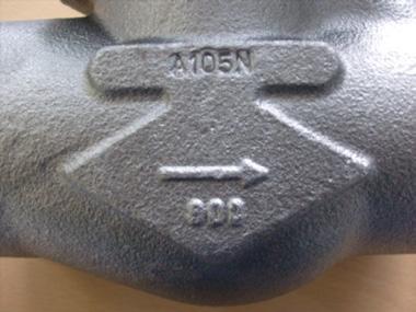
Check valves are unidirectional and have the direction of flow indicated on the valve body, as per Figure 1.
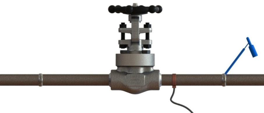
Australian Pipeline Valve piston and ball check valves are recommended for use in horizontal lines with bonnet facing up. Spring loaded APV ball check valves and y-type piston check valves can also be used in vertical line, see Figure 2.
Check valves must be fitted in horizontal pipe runs with the cover facing vertically upward. Variance to either side of the vertical axis must not exceed five (5) degrees. Swing-check valves and spring-loaded check valve designs can be positioned in vertical pipe runs with upward flow.
Check valves must not be installed in a vertical down flow pipe run or in a horizontal pipe run with the cover in the vertical down position. Always install valves in the direction indicated by the flow arrow stamped on the body. Note
Flow disturbances caused by the system components (e.g. pipe fittings, discharge of pumps, etc.) can lead to valve chatter, which can cause rapid wear of seats and trim and ultimately lea to valve malfunction. APV recommends that a sufficient distance be maintained between the check valve and any component that can cause flow disturbance as follows: a) System components that create flow disturbance - examples are pumps, fittings and valves. When installing a check valve near system components, APV recommends a minimum of 10 pipe diameters of straight pipe between the upstream system components and the inlet of the check valve and a minimum of 2 pipe diameters of straight pipe between the downstream system components and the outlet of the check valve. b) Pipe bends and transitions - examples are elbows, tees, branch connections and reducers. APV recommends a minimum of 10 pipe diameters of straight pipe between the upstream system component and the inlet of the check valve and a minimum of 4 pipe diameters of straight pipe between the downstream component and the outlet of the check valve.
CHECK VALVES - SWING, PISTON & BALL - API602/ISO 17561/B16.34
Spring loaded piston check valves are recommended for reciprocating compressor service in which a history of noisy check valve operation has been experienced.
Australian Pipeline Valve swing check valves may be installed in horizontal lines or vertical lines where the direction of flow (see Figure 1) as indicated on the valve body is upwards.
Note - Only spring loaded ball check valves, spring loaded piston check valves and swing check valves may be installed in vertical runs of pipe. Flow must be upward.
1.2 PREPARATION FOR INSTALLATION
• Remove protective end caps or plugs and inspect valve ends for damage to threads, socket weld bores or flange faces.
• Thoroughly clean adjacent piping system to remove any foreign material that could cause damage to seating surfaces during valve operation.
• Verify that the space available for installation is adequate to allow the valve to be installed.
1.3 END CONNECTIONS
1.3.1 Threaded Ends
Check condition of threads on mating piping. Apply joint compound to the male end of joint only. This will prevent compound from entering the valve flow path.
1.3.2 Flanged Ends
Check to see that mating flanges are dimensionally compatible with the flanges on the valve body and ensure sealing surfaces are free of debris. Install the correct studs and nuts for the application and place the gasket between the flange facings.
Stud nuts should be tightened in an opposing cris-cross pattern in equal increments to ensure even gasket compression. See Appendix A, Table A.
1.3.3 Socket weld Ends
Remove all debris, grease, oil, paint, etc., from the pipe that is to be welded into the valve and from the valve end connections.
Insert the pipe into the valve end connection until it bottoms out in the socket weld bore. Withdraw the pipe 1.59mm (1/16”) so that a gap remains between the pipe and the bottom of the socket weld bore to prevent cracks (ASME B1.11). Tack the pipe into the valve and complete the fillet weld.
1.3.4 Buttweld Ends
Clean the weld ends as necessary and weld into the line using an approved weld procedure. Make sure the pipe and valve body material given on the nameplate or valve body is compatible with the welding procedure. (Refer compatibility cross reference chart at the APV website for equivalent pipe, valve & fitting grades).
1.3.5 Valve Installation by Welding
Unless the valve contains PTFE packing and/or gasket, leave valves assembled during installation, welding and post-weld heat treatment. This will prevent the valve seat from floating or distorting during the process. After welding completion, open the valve and flush line to clean out any foreign matter.
Valves under 40mm (1.5”) fitted with a PTFE or elastomer bonnet gasket must be disassembled for installation as the welding temperature can adversely affect the PTFE components. Remove the bonnet and bonnet gasket and match mark each component during disassembly for proper reassembly. If you do not disassemble valves it will be the responsibility of the operator to ensure valves are kept cool during welding and then post-weld testing of the valve should be performed. Larger size valves over 40mm (1 1/2”) NB are less likely to transmit heat to bonnet gasket during welding but still care should be taken.
The responsibility for welding of the valves into piping systems is that of those performing the welding. Refer to ASME B31.1, B31.3 etc. Written welding procedures covering all attributes of the process and materials to be welded shall be in accordance with Section IX of the ASME Boiler and Pressure Vessel Code and any additional requirements from the applicable piping code including any possible necessary localised post weld heat treatment depending on material specifications.
APV forged globe, piston and ball check valves do not run the risk of seat loosening during welding due to the fact that they are supplied with integral Stellite body seats.
Subsequent to welding, clean and inspect the finished weld(s) and, if necessary, repair any defects using a qualified weld repair procedure. In addition, cycle the valve open-closed to check for proper operation, making sure no binding has occurred due to the weld heat.
Special trim options and body materials such as valves with PTFE packing/soft seat/special seals/ and gaskets that have maximum temperature limits less than the valve, may require special welding and heat treatment considerations which are not included herein.
1.3.6 Post Weld Heat Treatment (PWHT)
The recommended method of PWHT is via local ceramic resistance heaters, individually monitored with thermocouples. Thermocouples are attached to the weld or welds. Properly sized ceramic heaters are wrapped around the weld area, extending approximately 6.35mm (1/4”) past the weld on the valve side. Do not wrap the valve body with a heating element. See Figure 1 for details. Wrap flexible insulation around valve ends, extending approximately 12.5mm (1/2”) past the valve on the valves side. It is not recommended to wrap the entire valve body with insulation. Prior to heat input close the valve completely, then open the valve approximately 1.58mm (1/16”) of a turn after the handwheel slack is run out. This very slight opening will allow the trim components to expand during the thermal cycle. Following PWHT, inspect the valve for smooth operation by cycling open and closed. If possible, perform a seat closure pressure test prior to service operation.


1.4 POST-INSTALLATION PROCEDURES
After installation, the line should be cleaned by flushing to remove any foreign material. When caustics are to be used to flush the line, additional flushing with clean water is required. The valve should be opened and closed after installation to ensure proper operating function. With the line pressurised, check the valve end connections, body to bonnet/cover joints and external plugs for leaks.
2.0 OPERATION
The check valve operation is automatic and requires no assistance. When the flow exerts sufficient pressure against the disc to overcome the disc’s weight, the disc allows the flow to continue through the piping system. As pressure decreases, the disc lowers until it’s own weight forces it to seat. This prevents the possibility of a reversal in the flow. Piston and ball check valves should not be used in applications where rusting or rust particles are present or anticipated. Swing check valves are more tolerant for applications of this nature.
Metal seated check valves (piston, ball and swing) are not zero leak devices and may “seep” in service. This type of valve should always be backed up with an isolation valve (either gate or ball valve). Check valves are designed to prevent reverse flow. Leakage rates for check valves with metal-to-metal seats are dependant on the amount of back pressure and the viscosity of the flowing medium. Soft seat check valves can offer improved leak tightness provided there is sufficient back pressure. Check valves should not be used in gas or low back pressure liquid applications if zero leakage is desired.
2.1 PISTON CHECK/BALL CHECK VALVE
A typical bolted bonnet piston check and ball check are shown in Figure 7; an exploded view is shown in Appendix B. The bodies (8) of the piston check valve and the ball check valve are of the same labyrinth design as that of the globe valve. The barrier of flow is a free moving piston (6) that is guided by the body (8) or a free moving ball (10) that is guided by the bonnet (4). The piston check and ball check also have an integral seat (7) (renewable seats also an option), against which either the piston (6) or the ball (10) seat to provide stoppage of flow. The piston (6) or ball (10) drop into the seat (7) by gravity during no-flow conditions and open by fluid pressure on the upstream side (from underneath the piston (6) or ball (10). Reversal of fluid flow forces the piston (6) or ball (10) back into the seat (7) which stops the flow.
The piston and ball check valves are designed for horizontal service; however, these valves can be equipped with an internal spring (9) which allows the valve to be used in vertical up service, as shown in Figure 2.
2.2 SWING CHECK VALVE
A typical bolted bonnet swing check valve is shown exploded view in Appendix B. The swing check valve is a straight-through flow check valve equipped with a disc (7) which rests against the seat (9) under no-flow conditions. The seat (9) is pressed into the valve body (11) and is of the removable design. A hinge (5) supports the disc (7) from a hinge pin (8) which is set in the valve bonnet (6). The supporting hinge (5) allows the disc (7) to swing freely away from the seat (9) because of the flow pressure being exerted upon the disc’s upstream side. A reversal of fluid flow exerts pressure on the downstream side of the disc (7) forcing it against the seat (9) and stopping the flow.
A check valve should not be used as a primary means of isolation for any application because a check valve may not provide a leak-tight (no through leakage). Only gate or globe valves should be used for isolation.
3.0 MAINTENANCE
No periodic maintenance is necessary unless special external accessories are fitted.
4.0 REPAIRS
Proper safety equipment and apparel should be worn when preparing to service a valve. Observe the following general warnings:
• A valve is a pressurised device containing energised fluids and should be handled with care.
• Valve surface temperature may be dangerously too hot or too cold for skin contact.
• Upon disassembling, attention should be paid to the possibility of releasing dangerous and or ignitable fluids.
• Adequate ventilation should be available for service.
4.1 REPAIR INSTRUCTIONS
Due to the relatively low replacement cost of small diameter standard carbon steel valves especially under 80 NB (3”), it is usually less expensive to replace the complete valve than to have maintenance personnel effect repairs. Generally, the only viable repairs are replacement of bonnet gasket. However, see Section 4.2 and 4.3 below for further extraordinary repairs.
Always replace the bonnet gasket whenever a valve is disassembled. Gasket seating surfaces should be scraped clean (avoid radial marks). Bonnet bolts should be tightened in a diagonal pattern at several different increasing torque settings in accordance with the recommended torque value (see table Appendix A, Table A and Figure 6).
4.2 DISASSEMBLY & GASKET REPLACEMENT
Before disassembling:
1. Check that the line is in a complete shut down phase, then remove the valve from pipeline.
2. Pre-order all necessary spare parts and joining gaskets.
3. Put identification markings on valve body, disc and bonnet. This helps to avoid mismatching of parts at the time of re-assembly.
4. If the bolts and nuts are too tight, apply deep penetrating oil and then unscrew.
Disassembly:
1. Disassemble all cover bolts and nuts.
2. Gently break the seal with a lever, gradually lifting the bonnet flange at intervals 360° around the bonnet.
3. Clean gasket surface areas, replace gasket and refit bonnet as detailed in 4.1 above.
4. ‘Pressure seal’ valves use a proprietary gasket.
4.3 VALVE INTERNALS DISASSEMBLY INSPECTION AND REPAIR
1. Check that the (where applicable) hinge, nut and pin are in good condition and firmly connected. Replace damaged parts as necessary.
2. For swing check valves, lift and remove the disc hinge assembly. Movement should be free and not hindered by any malfunction of the hinge pin. Where disc travel is not sufficiently smooth, remove plugs or blind flanges and then remove hinge pin. Check surface for seizure or scraping marks. If marks are deeper than 1.5mm (1/16”), re-machine hinge pin and reassemble hinge pin and reassemble. If defect depth is greater than 1.5mm (1/16”), a new hinge pin is necessary. When reassembling hinge pin, it is recommended that the disc be removed by loosening the nut. For piston check or ball check valves, if there is a spring ensure it is functioning properly and is sufficiently energised. The spring should hold the disc/ball tightly against the seat no matter what position the valve is in.
3. When leakage is due to deterioration of seal surfaces caused by corrosion, erosion or foreign substances, it must be determined whether the disc or seal seat are the cause. Where special soft seat inserts are supplied, consult APV.
a) Deterioration of disc surfaces: b) Deterioration of seat seal surfaces:
Swing check valves: - Disassemble disc by removing nut and washer. (Ball/Piston check valves have a free floating disc). Repair surface by grinding and relapping using a fine grade abrasive paste.
When seal surfaces are damaged and defects are confined to a small area but are not deeper than 0.4mm the seal surface can be relapped. For smaller sizes the recommended method is to use a cast iron strap with an outside diameter matching the valve’s raceway. If the seat surfaces cannot be relapped an APV approved repairer will decide if the surface has to be reground/re-machined or replaced. When defects are deeper than 0.4mm and found on the entire surface, re-metallising or a new seat is required. For threaded-in seats it is recommended that an anti seizure compound be used when installing the replacement seat to make threading it in the body easier.
Always be sure that the valve is de-pressurised and isolated prior to performing any maintenance work. Remove any dangerous fluids from valve before commencing maintenance.
Check valves do not require lapping fixtures as the bore of the valve body serves as a guide. On ball check valves the rolling action of the ball retains seating surfaces in good condition until ball size or ball guide is worn and replacement parts are needed.
After lapping, it is recommended that the surface of the seat and disc be checked for proper contact using the marking blue. Coat the seats with marking blue, and tightly screw the disc into the seats. Unscrew the disc, and examine to make sure there is continuous contact between the sealing surfaces of the disc and body seat.
Typical Forged Bolted Piston Check Valve Exploded View
The seat ensures a stable shut off. The seat is precision ground for optional seating.
The cover gasket creates a leak-proof seal between the bonnet and the body.
Piston is machined to the tightest tolerances to ensure trouble free shut off and cycling.
The spring is precision made and loaded for precise pressures.
The cover allows access to internal components.
The cover studs secure the bonnet to the body.
Forged steel bodies provide low resistance flow and optimum strength and performance.
Sample only refer to as built drawing as there are numerous styles and designs also vary depending on size & class.

