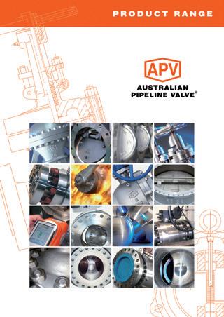
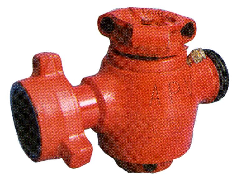
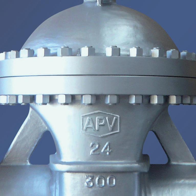
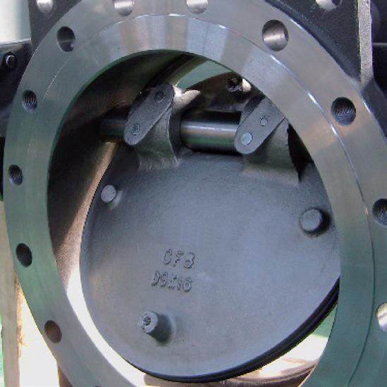
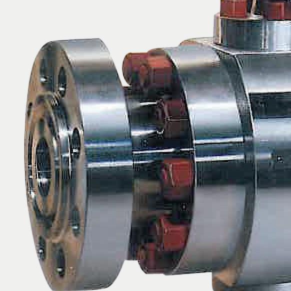
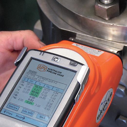
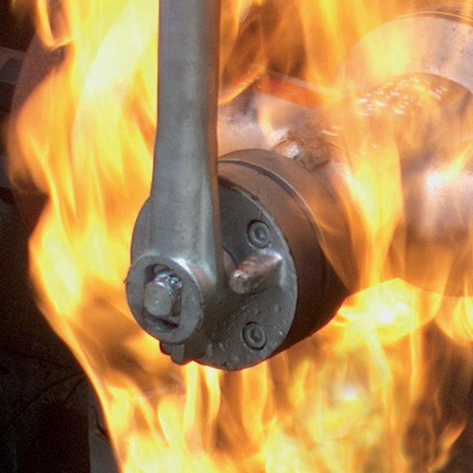
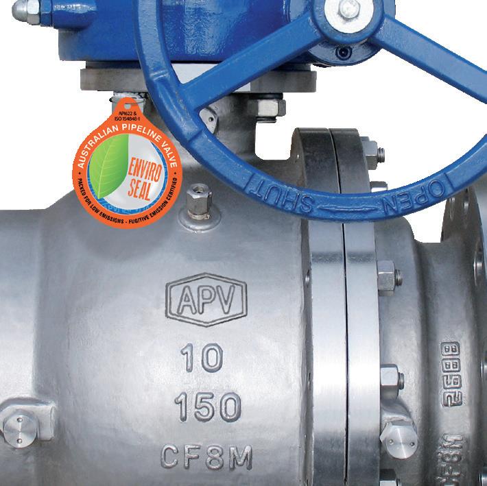
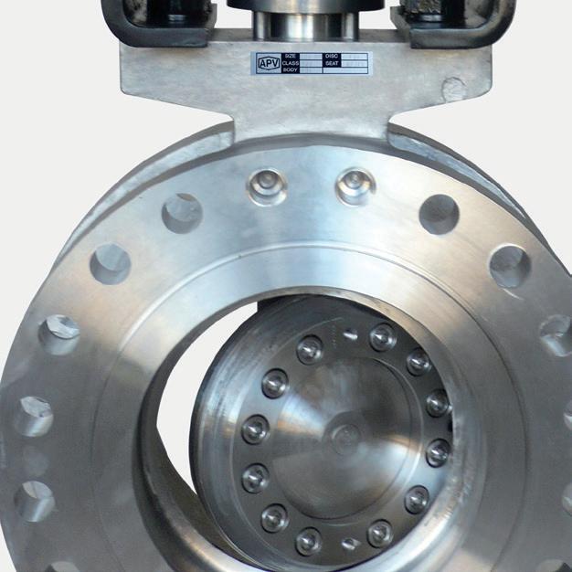
“Australian Pipeline Valve produces isolation, control and flow reversal protection products for severe and critical service media in utility, steam, pipelines, oil & gas and process industries. APV valves and pipeline products form the most competitive portfolio in the market.”
APV FAMILY OF BRANDS RANGE - CATALOGUES
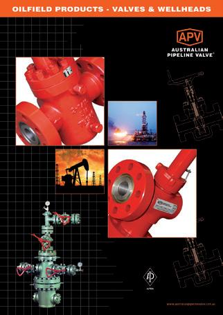
Oilfield Products Valves & Wellheads
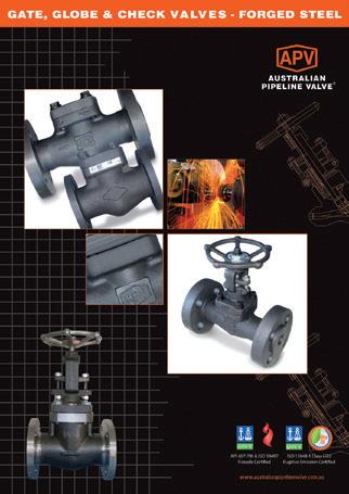
Gate, Globe & Check Valves - Forged Steel
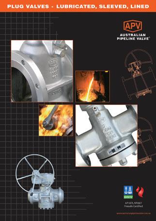
Plug Valves Lubricated, Sleeved & Lined
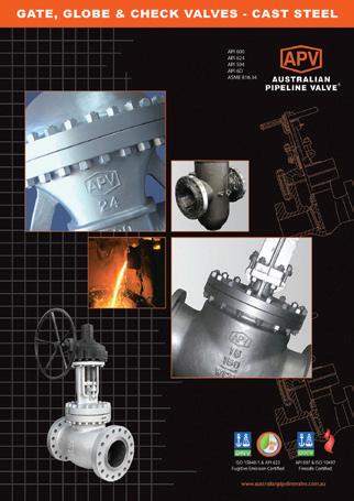
Gate, Globe & Check Valves - Cast Steel
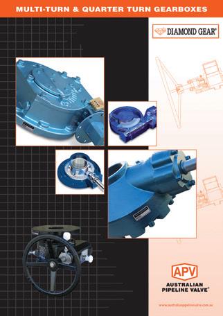
Diamond Gear Gearboxes
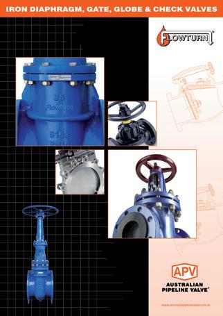
Flowturn Gate, Globe & Check Valves
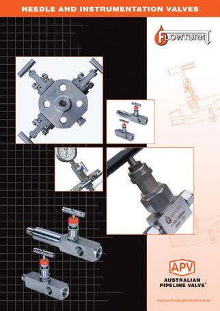
Flowturn Instrument Valves
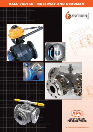
Flowturn Ball Valves Multiway & Deadman
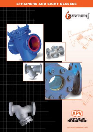
Flowturn Strainers & Sight Glasses
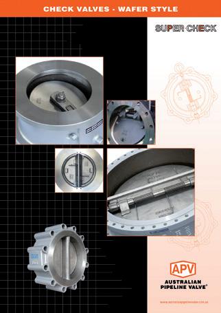
Supercheck Wafer Check Valves
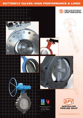
Superseal Butterfly Valves
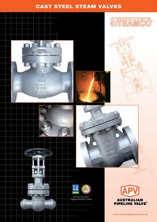
Steamco Steam Valves
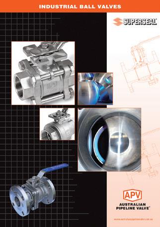
Superseal
Industrial Ball Valves
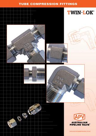
TwinLok Tube Fittings
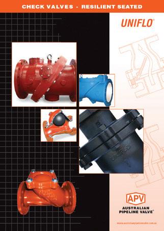
Uniflo Check Valves
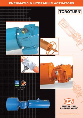
Torqturn Actuators
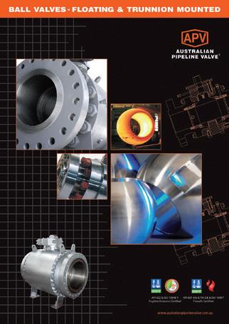
Ball Valves Floating & Trunnion Mounted
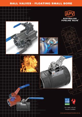
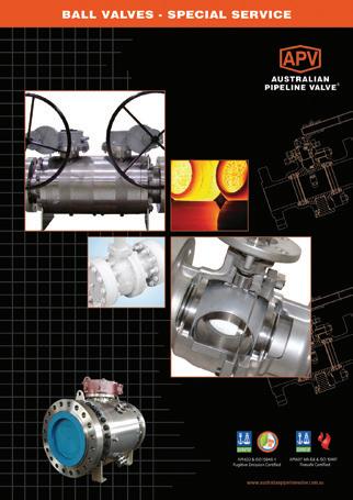
Ball Valves Floating Small Bore Ball Valves Special Service
Product Brochure
INTRODUCTION
The majority of this information is common knowledge to experienced valve users. When properly installed in applications for which they were designed, Australian Pipeline Valve (APV) valves will give long reliable service. This instruction is only a guide for installation and operation on standard service and covers general maintenance and minor repairs. A professional APV approved valve engineering facility should be utilised for reconditioning or major repairs.
Note
We do recommend however that this entire document be read prior to proceeding with any installation or repair. Australian Pipeline Valve and it’s parent company take no responsibility for damage or injury to people, property or equipment. It is the sole responsibility of the user to ensure only specially trained valve repair experts perform repairs under the supervision of a qualified supervisor.
RESPONSIBILITY FOR VALVE APPLICATION
The User is responsible for ordering the correct valves. The user is responsible for ensuring APV Valves are selected and installed in conformance with the current pressure rating and design temperature requirements. Prior to installation, the valves and nameplates should be checked for proper identification to ensure the valve is of the proper type, material and is of a suitable pressure class and temperature rating to satisfy the requirements of the service application.
Do not use valves in applications where either the pressure or temperature is higher than the allowable working values. Also, valves should not be used in service media if not compatible with the valve material of construction, as this will cause chemical attacks, leakage and valve failure.
RECEIVING INSPECTION AND HANDLING
Valves should be inspected upon receipt to ensure:
- Conformance with all purchase order requirements.
- Correct type, pressure class, size, body and trim materials and end connections.
- Any damage caused during shipping and handling to end connections, hand wheel or stem.
The User is advised that specifying an incorrect valve for the application may result in injuries or property damage. Selecting the correct valve type, rating, material and connections, in conformance with the required performance requirements is important for proper application and is the sole responsibility of the user.
SAFETY INFORMATION
The following general safety information should be taken in account in addition to the specific warnings and cautions specified in this manual. They are recommended precautions that must be understood and applied during operation and maintenance of the equipment covered in this I.O.M
To avoid injury, never attempt disassembly while there is pressure either upstream or downstream. Even when replacing gaskets, caution is necessary to avoid possible injury. Disassemble with caution in case all pressures are not relieved.
To prevent valve bending, damage, inefficient operation, or early maintenance problems, support piping on each side of the valve. Warning, certain gases and fluids could cause damage to human health, the environment or property, hence the necessary safety precautions to prevent risk should be taken.
This manual provides instructions for storing, general servicing, installation and removal of Plug valves. When using these assemblies, appropriate protective equipment is required: safety glasses, approved safety shoes and hard hats must be worn. Hammering and lifting these assemblies must be done with caution.
Personnel should only hammer on makeup lugs and not strike union nut or valve body. Fractures can occur from repeated misuse. Excessive hammering can damage components. Proper leg lifting should be used when lifting. Back lifts should be avoided. It is a personal responsibility to become knowledgeable and trained in the proper use and handling of this tool. Do not hammer on, or be around valve assemblies when pressure is present. Hand actuation (with the appropriate Actuator bar) should be done only by specially trained personnel under direct supervisory instruction; and only when necessary due to application.
Valve unions should be clean and lightly oiled before each use, as well as a visual inspection for damage. Union seals should be checked and replaced when worn or damaged. Each valve has a size and pressure code designated on the valve. Use this code for proper mating and pressure limits.
Since plug valves may be painted in different colours for various applications, it is suggested not to use factory colour as a primary means of identification.
APV and it’s re sellers refuse any liability for damage to people, property or plant as well as loss of
production and loss of income under any circumstances but especially if caused by: Incorrect installation or utilisation of the valve or if the valve installed is not fit for intended purpose. It is the sole responsibility of the user to ensure the valve type and materials are correctly specified.
DURING OPERATION TAKE INTO ACCOUNT THE FOLLOWING WARNINGS:
a- Graphite/Graphoil packing and body gasket is very brittle, any impacting, twisting or bending should be avoided.
b- The valve’s internal parts such as disc, stem, seats, seals, gaskets shall be handled with care avoiding scratches or surface damage.
c- All tools and equipment for handling the internal parts shall be soft coated or else take extreme care, especially on machined mating surfaces and with soft parts.
d- Valves can be fitted with gaskets or seals in PTFE, Buna, Viton, etc., hence high temperatures will damage sealing components.
For all operations make reference to position number on part list of the applicable drawing listed.
1.0 INSTALLATION
Where applicable, piping should be properly aligned and supported to reduce mechanical loading on the end connections.
1.1 INSTALLATION POSITIONS
Plug valves are usually bidirectional and therefore may be installed in either direction. In some cases, Plug valves may be unidirectional, in which case the direction of flow will be indicated on the valve body.
1.2 PREPARATION FOR INSTALLATION
• Remove protective end caps or plugs and inspect valve ends for damage to threads, socket weld bores or flange faces.
• Thoroughly clean adjacent piping system to remove any foreign material that could cause damage to seating surfaces during valve operation.
• Verify that the space available for installation is adequate to allow the valve to be installed and to be operated.
Ensure sufficient clearance for the stem in the full open position may cause the valve to be inoperable. Inadequate clearance for valve may add mechanical loading to the valve ends. Sufficient clearance should be allowed for threaded valves to be ‘swung’ during installation.
1.3 END CONNECTIONS - INSTALLATION
1.3.1 Threaded Ends
Check condition of threads on mating pipe.
Apply joint compound to the male end of joint only. This will prevent compound from entering the valve flow path.
1.3.2 Flanged Ends
Check to see that mating flanges are dimensionally compatible with the flanges on the choke and ensure sealing surfaces are free of debris.
Install the correct studs and nuts for the application and place the flange gasket between the flange facings.
Stud nuts should be tightened in a an opposing criss-cross pattern in equal increments to ensure proper gasket compression.
1.3.3 Buttweld Ends
Clean the weld ends as necessary and weld into the line using an approved weld procedure. Make sure the pipe and body material given on the nameplate is compatible with the welding procedure.
1.3.4
Valve Installation by Welding
Leave valves assembled and in the lightly closed position during installation, welding and post-weld heat treatment. This will prevent the valve seat from floating or distorting during the process. After welding completion, open the valve and flush line to clean out any foreign matter.
Stem seal leakage could result in personal injury. Valve stem area is tested prior to shipping but should be again checked to ensure no leakage.
Check the stem sealing area for pressurised process fluids even after the valve has been removed from the line, particularly when removing seals or fittings.
Personal injury may result from sudden release of any process pressure. APV recommends the use of protective clothing, gloves and eye wear when performing any installation or maintenance.
Isolate the valve from the system and relieve pressure prior to performing maintenance.
Disconnect any operating line providing air pressure, control signals or electrical power to actuators.
When removing or adjusting gasketed parts, APV recommends installing a new gasket before reassembling. A proper seal is required to ensure optimum operation.
2.0 OVERVIEW
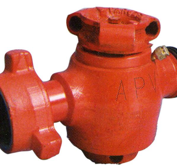
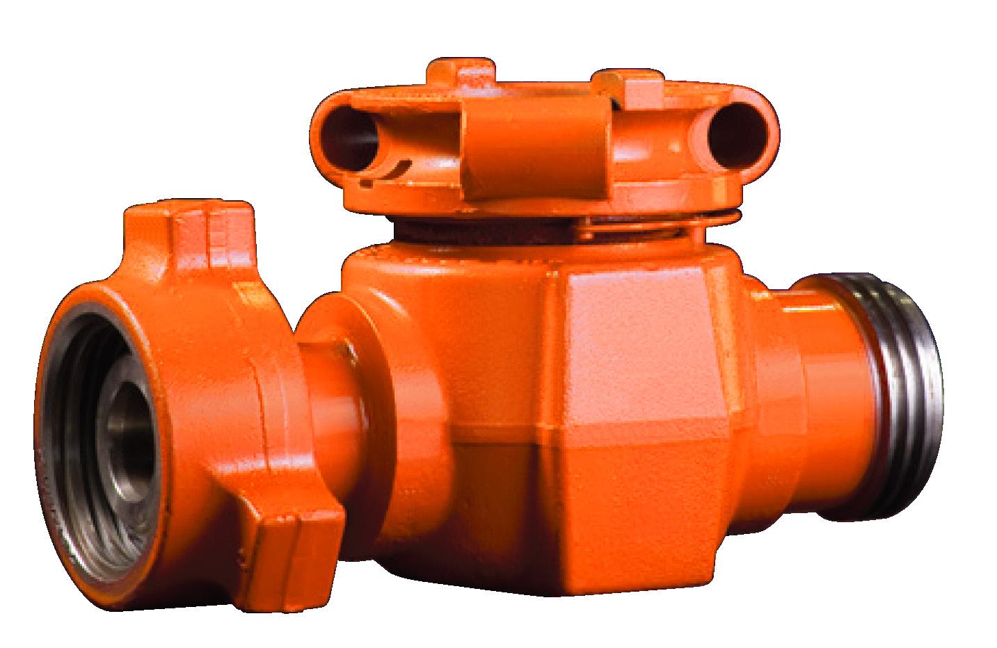
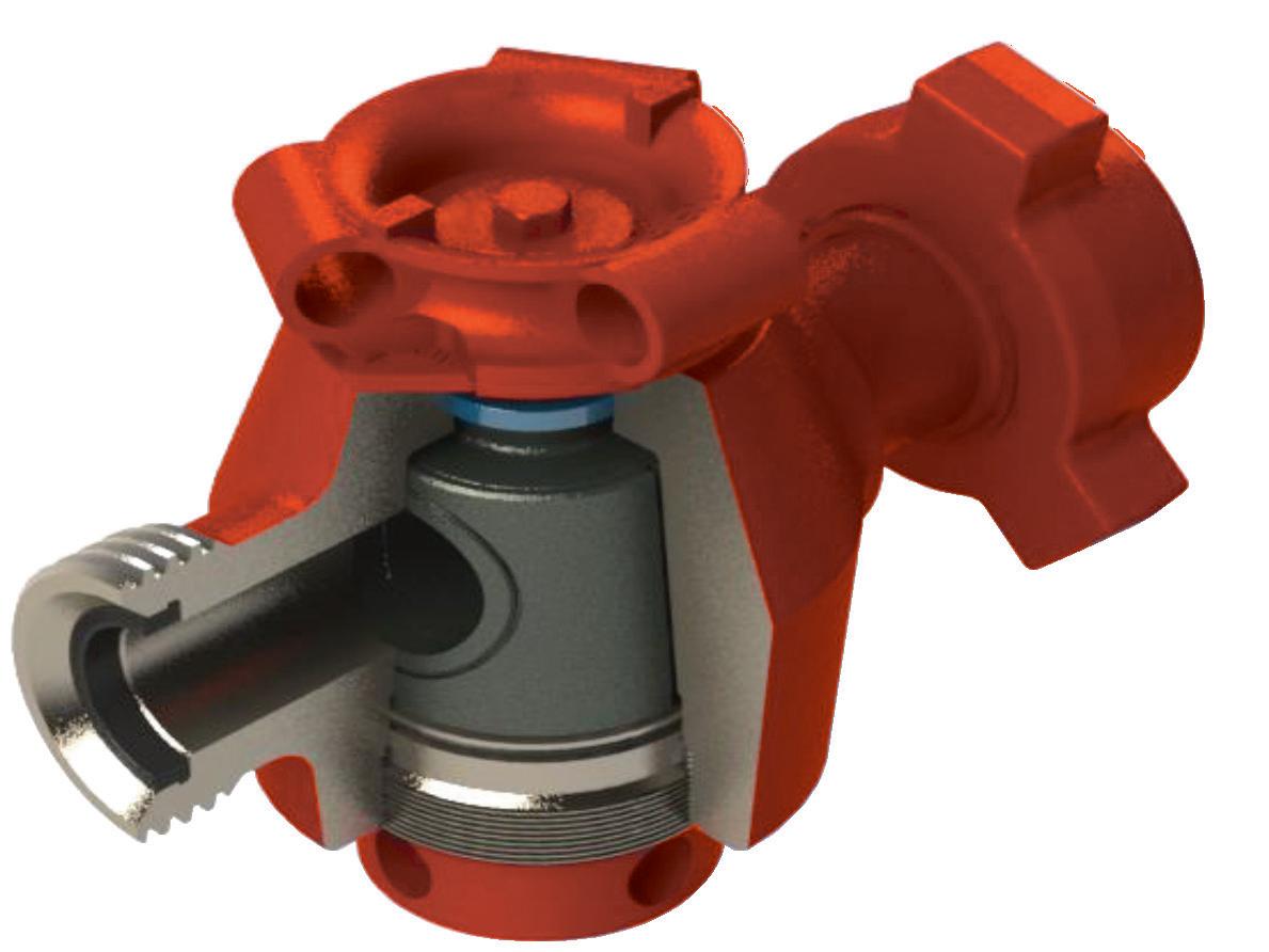
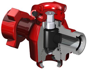
The Plug valve, with superior design features and precision workmanship is proven to meet the harsh drilling requirements in today’s oil fields. The regulated design of the plug valve allows the flow through the plug valve bore and can be completed stopped by rotating the plug 90°. This can be manually, or with pneumatic or hydraulic actuators. Pressure drop across the valve is low as they add little disturbance to the flow. They are simple to operate, fast to respond and require minimal space. The valve standard trim includes 410 or 316SS plugs, 410 or 316SS stems and BUNA N seats, optional trims are available which include Ni plated, stellite, carbon steel, monel and aluminium bronze plugs. Seats are offered in Viton and Hypalon, and optional 17-4 pH or 303SS stem is available. 410SS is used for high H2S service plug valves which conform to NACE MR-01-75 for exposure to H2S.
2.1 CONSTRUCTION
All the valves conform to API flange specifications in all pressure class ratings.
2.2
APPLICATIONS
• Drilling and well-treating chemicals
• Sour gas and crude oil
• Abrasive drilling mud
• Water, oil and gas lines
• Cements and slurries
It is important that the correct plug valve be used for the specific application.
3.0 OPERATION
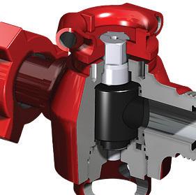
APV quarter turn plug valves have a taper seal. The inside body is tapered to ensure a uniform clamping action for the initial seal. As pressure is introduced to the valve, the plug and inserts are allowed to float downstream to act as a seal as the inside body wall is encountered. As pressure increases, the differential pressure becomes greater assisting the effectiveness of the seal. The torque then required is minimised due to the relationship between the seal and the bearing area.
3.1 PRECAUTION DURING OPERATION
• At times it may be necessary to turn the valve when pressure is present. APV recommends the use of remote control Actuators for this purpose. In cases where this is not feasible, exposure time around pressured lines during valve operation should be kept to a minimum and only by experienced personnel.
• Before applying pressure, valves should be greased in both the opened and closed position. If valve is excessively hard to operate, becomes plugged, or does not operate properly it should be removed and not used until repairs are made.
• When opening a plug valve under pressure, the initial torque to start the stem turning is always greater than the moving torque. You must position your body to be able to compensate for this change.
• Never look into, or position yourself in the path of the exit flow of the valve.
• Condsider the exit position any plug valve, used for bleeding. This needs to be situated away from rocks or debris that may be picked up by the exit stream.
• If valve is slow to open or close, remove it from service. Do not hammer on the valve’s Actuator cap.
• Operation rate in excess of 42 feet per second be avoided. Rates above this will cause more rapid wear and erosion.
• Never alternate a valve’s service; acid service should never be followed by cold temperature service.
• If acid etching or erosion is present, the valve should be replaced.
• The pressure code as shown on each integral union connection nut should not be exceeded. To avoid failures this code should also be used when mating unions. All integral union connections must match (according to size, pressure rating, etc.). These connections must also match the service of the designated string they are installed in.
4.0 MAINTENANCE
Before the valve can be inspected it must be cleaned thoroughly with steam or soap & water. The use of solvents is to be avoided as this may damage the elastomer seals.
• Inspect the plug, inserts, adjusting nut, seals and the valve for wear or damage.
• Clean out all of the old lubricant from the valve body’s internal profile and all parts.
When using sandpaper on sealing surfaces, avoid repetitive sanding in one spot; sand evenly across the entire sealing surface. Sand scratches by moving the sandpaper around the plug, not up and down, along the length of the plug.
As part of a regular maintenance program the valve should be regularly greased to increase the service life of the internal parts of the valve. Routine disassembly and cleaning as part of a maintenance program can help prevent unnecessary damage to the valve body.
Valves should be greased depending on the severity of their use. APV can help you establish guidelines for a greasing and/or disassembly program based on the operating conditions. For disassembly procedures refer to section 5.0 of this manual.
To prevent leakage, malfunctions resulting from internal wear or seal degradation, the user must establish a preventative maintenance and inspection program according to the usage. This program must include:
a) Inspection of parts to detect loss of wall thickness that may result in decreased pressure capacity.
b) Routine replacement of seals and inspection for proper operation.
5.0 DISASSEMBLY
5.1 LT STYLE
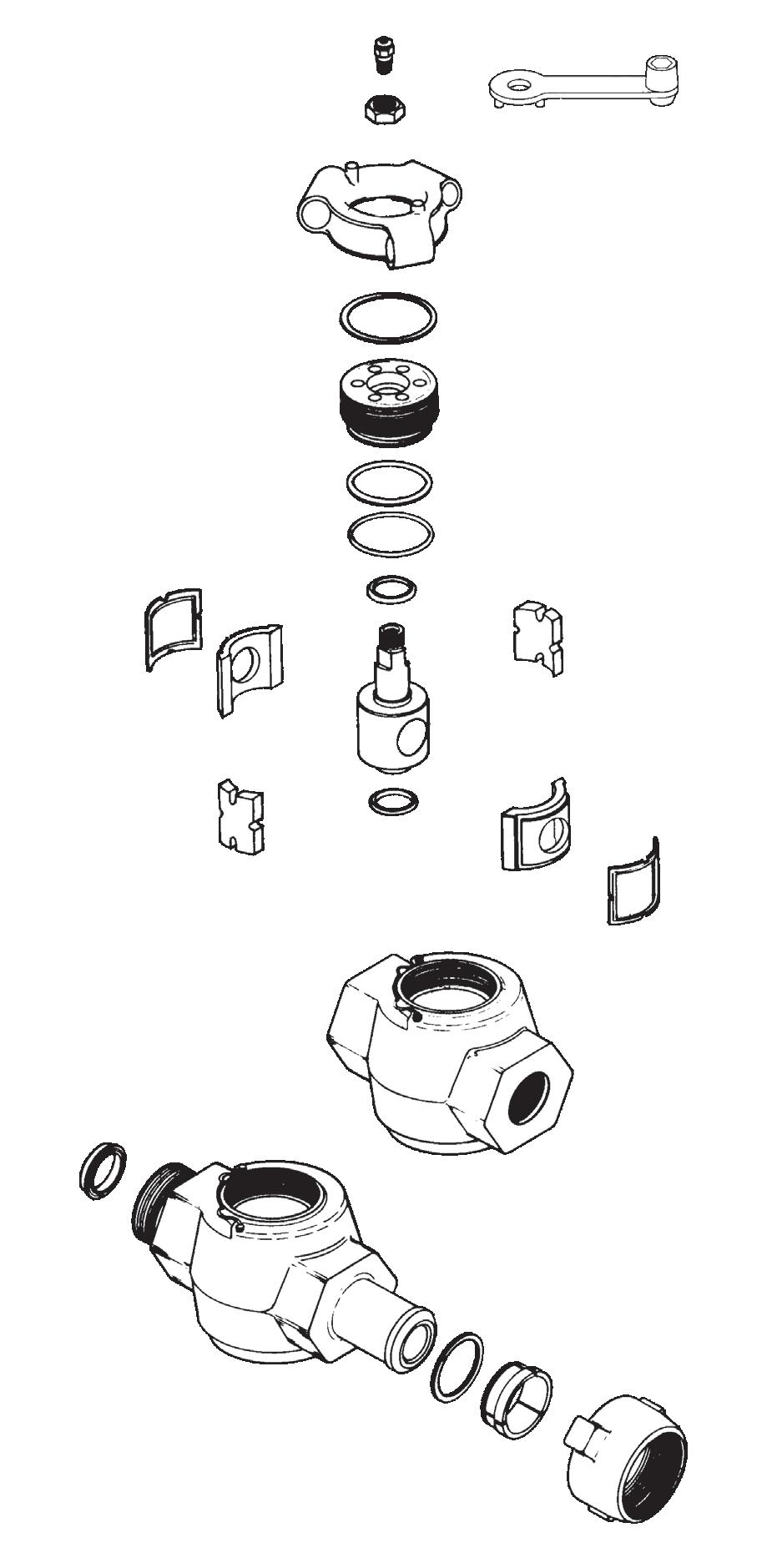
Plug valve disassembly procedure is as follows: -
1. Hold tight the valve body (1) or end connections for approach to top or bottom of valve.
2. Remove hex bolt (15), washer (12,14), handle (11) adjusting nut (7), cap screw (9), top collar (10) from both end top & bottom.
3. Plug can be removed with a gentle push with a wooden block.
4. Remove insert o-ring (5), adjusting nut o-ring (8) and plug seal (6).
Always replace o-ring and seals after every opening
Note
5. Insert, plug valve body & adjusting should be inspected for corrosion, wear in seal area or scoring.
6. Internal profile of the valve should be thoroughly cleaned after removing all old lubricants.
NOTE: For SP Style Disassembly refer to APV. We will supply relevant OEM IOM on request.
6.0 ASSEMBLY
6.1 LT STYLE
Plug valve assembly procedure is as follows: -
Ensure the work area for assembling the valve is clean and free from contaminants e.g. dust, dirt, metal, particles etc. these may mix with the lubricant causing damages to the natural working of the valve.
Note
1. Check through the bore inside the pocket and de burr any sharp edges.
2. Check the dowel pins (2) that are in the valve body by gently dropping a set of inserts (4) into the valve. The inserts should move freely up and down the distance of the roll pin slots.
3. Screw the clean adjusting nut (7) all the way into the valve body to check the threads are not damaged. Remove after inspection.
4. Apply stick grease in the o-ring groove and install the insert o-rings (5) and the adjusting o-ring (8).
5. Check the plug (3) O.D. & insert surface for defects such as scratches, nicks, etc. that could possible affect the sealing area.
6. Apply valve grease in the internal profile of the body; plug (3) and inserts (4). For valve greasing procedure refer to 6.1 of this manual.
7. Install the plug seals (6) into the recess of the valve body and adjusting nut with the metal back up towards the recess and facing away from the pressure.
8. Install the lower end of the plug (opposite the hex end) in the adjusting nut and push down until the plug shoulders.
9. Place the inserts around the plug and secure the plug to the adjusting nut with a hex bolt (15) and washer (12,14). Plug and insert ports must be aligned.
10. Fix the plug with inserts and adjusting nuts (with o-rings and seals in proper place) into the valve body with the alignment pins keying into the insert alignment slots.
11. Apply recommended torque to tighten adjusting nut into the body. This will ensure proper sealing.
RECOMMENDED TORQUE AT HYDROSTATIC TEST CONDITIONS
12. Fix stop collar (10), handle (11) on top of the valve and secure with a hex bolt (15) and washer (12,14).
Note: 1” valves do not require a stop collar.
13. Valve should be greased thoroughly using stick grease by rotating the plug a number of times while pumping in stick grease through greasing nipple (16).
NOTE: For SP Style Assembly refer to APV. We will supply relevant OEM IOM on request.
6.2 VALVE GREASING PROCEDURE
Plug valve greasing procedure of plug valve is as follows: -
1. During assembly he body I.D. and adjusting threads are to be greased with Chevron ultra-duty type 2 red shop grease by hand (CPS no. 254600).
2. VAL-TEX 972K valve stick grease is to be applied to the inserts I.D. and the plug O.D.
3. Complete the assembly of the valve.
4. Before testing, inject the stick grease into the valve with a high pressure grease gun through greasing nipple with the valve in the open position. For injecting grease the grease gun should be pressurised approximately 3,500 PSI.
5. Should the grease gun start building up pressure the valve should be closed to relieve pressure and re open.
6. Grease again until pressure builds up or until excess grease starts entering the bore.
7. Close the valve to bleed pressure buildup and then re open the valve.
Listed below is the amount of grease injection required relative to the valve size.
7.0 TESTING
Refer to API 6A latest edition for testing procedures. Prior to pressure testing, valve adjustment is to be carried out.
7.1 VALVE ADJUSTMENT PROCEDURE
a) Close the plug and apply hydrostatic pressure less than equal to 50% of the full working pressure.
b) Bleed off the pressure by opening the plug.
c) Tighten the adjusting nut to the correct torque (typically the adjusting nut will tighten at least another 90 degrees).
d) Repeat the procedure for the other side to complete the valve adjustments.
Valve adjustments rely on the plug being settled into the inserts by differential pressure. The differential hydrostatic pressure forces are many times greater than the force applied by the adjusting nut alone.
Valve adjustment is used to remove excess grease from the space between plug and inserts and makes for more reliable valve performance. In cases where the valve has not been adjusted, the fit between plug and inserts will be loosened after the first seat test. This results in unreliable seal energising for further testing.
8.0 STORAGE
The following are steps to ensure proper plug valve storage: -
a. All equipment should be drained and lubricated after testing and prior to storage.
b. All components and assemblies should be cleaned free of dirt, oil, metal particles and other contaminates.
c. Equipment containing exposed metallic surfaces should be protected with a rust inhibitor which will not become a fluid and run at temperatures less than 52°C (125°F).
d. Exposed sealing surfaces should be protected from mechanical damage.
8.1 SHELF LIFE
The following maximum equipment shelf life recommendations are a guide only, refer to the manufacturers recommendations for storage.
Stored 0-3 months Nothing required
Stored 3-6 months Re-grease and operate. Operate by rotating the plug. Check to see that rotation is smooth without grinding or scraping.
Stores 6+ months Disassemble, rebuild & retest the valve. Replace all internal seals.
APPENDIX A
BILL OF MATERIALS - LT STYLE
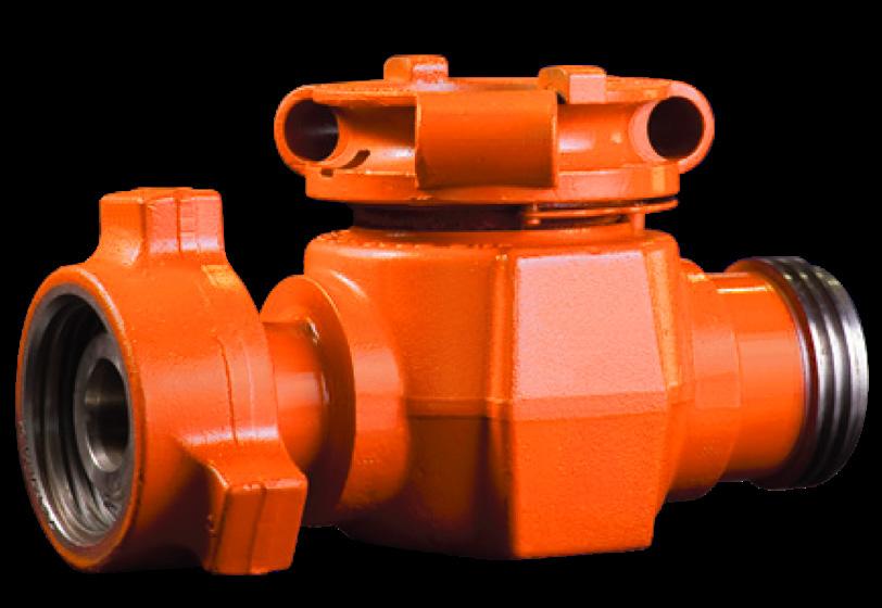
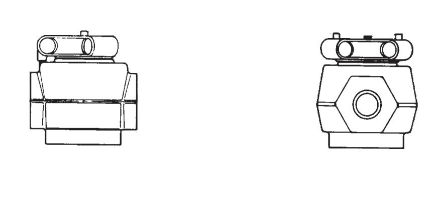
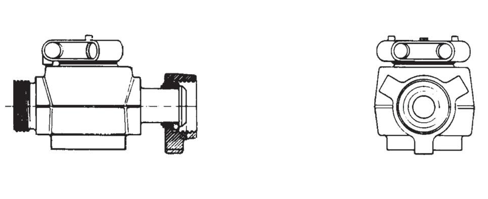
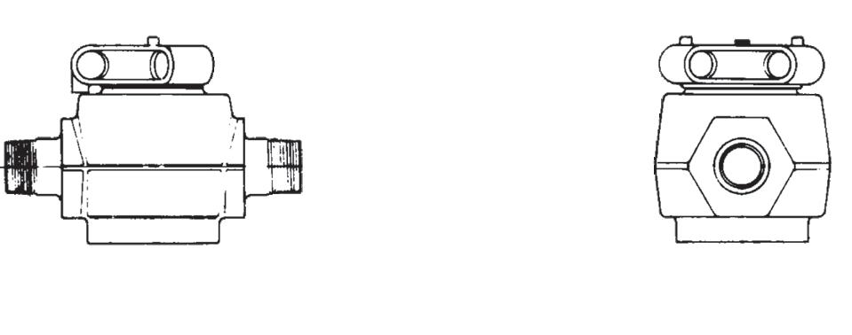
Quarter-turn valves for standard and sour gas services to 20,000 psi. Rugged plug valves 1 to 3 inches and with threaded or detachable Weco®™* style wing union ends. Used for cementing, fracturing, acidizing and other high-pressure lines which handle slurries, abrasives, drilling muds, chemicals and other similar products. These valves are equivalent to Lo-Torc®™* style.
Floating segments ensure positive seal
Two seal segments which float slightly to offset possible micro-expansion of the valve body in extreme high-pressure applications and to ensure a positive seal at all times. Easy operation under pressure
The plug valve’s cylindrical plug fits between a set of seal and side segments to prevent the plug from sticking to the valve body, permitting easy operation under pressure. Visible indication of valve position
A visible, quarter-turn stop on the plug cap indicated clearly when the valve is fully open or fully closed. A detent spring holds the valve in the desired position. In-line maintenance
Can be rebuilt in-line by replacing the side and seal segments.
MATERIALS
APPENDIX A CONT.
BILL OF MATERIALS - SP STYLE
Quarter-turn valves for standard and sour gas services to 20,000 psi. Rugged plug valves 1 to 3 inches and with threaded or detachable Weco®™* style wing union ends. Used for cementing, fracturing, acidizing and other high-pressure lines which handle slurries, abrasives, drilling muds, chemicals and other similar products. These valves are equivalent to SPM®™* style. We can also supply model MC-OD-PV which is equivalent to Lo-Torc®™* style (even parts interchange).
Floating segments ensure positive seal
Two seal segments which float slightly to offset possible micro-expansion of the valve body in extreme high-pressure applications and to ensure a positive seal at all times. Easy operation under pressure
The plug valve’s cylindrical plug fits between a set of seal and side segments to prevent the plug from sticking to the valve body, permitting easy operation under pressure.
Visible indication of valve position
A visible, quarter-turn stop on the plug cap indicated clearly when the valve is fully open or fully closed. A detent spring holds the valve in the desired position. In-line maintenance
Can be rebuilt in-line by replacing the side and seal segments.
MATERIALS
APPENDIX B
DIMENSIONAL DETAILS
1
1
2
2
2
3
3“
APPENDIX C
RECOMMENDED MINIMUM PSL FOR PRIMARY PARTS
NACE
High H2s Concentrate
Close Proximity*
Rated Working Pressure, PSI
* See paragraph A5 of API 6A 17a. Ed.
PR1 is standard
PR2 also available (increased cycle times on test required)
API MATERIAL REQUIREMENTS
MINIMUM MATERIAL REQUIREMENTS
MATERIAL CLASS
BONNET & FLANGE
AA - General Service Carbon or low alloy steel
BB - General Service
CC - General Service
DD - Sour Servicea
EE - Sour Servicea
FF - Sour Servicea
HH - Sour Servicea
As per API 6A (ISO 10423) 2013:
a As defined by ISO 15156 (all parts) (NACE MR0175) (See API 6A)
b In compliance with ISO 15156 (all parts) (NACE MR0175) (See API 6A)
or low alloy steel
Steel
or low alloy steelb
or low alloy steelb
Steelb
c CRA required on retained fulid-wetted surfaces only; CRA cladding or low-alloy or stainless steel is permitted (See API 6A)
d CRA as defined in API 6A; ISO 15156 (all parts) (NACE MR0175; see API 6A) definition of CRA does not apply.
or low alloy steel
or low alloy steelb
APPENDIX C CONT.
API TEMPERATURE REQUIREMENTS
TEMPERATURE CLASSIFICATION
* No longer referenced in API 6A/ISO 10423-2013
API PRESSURE/TEMPERATURE RATINGS (Y)*
* Based on ‘Y’ Temp. Due to elastomers, Plug Valves are temp ‘T’ or ‘U’ as standard hence consult separate chart.
PSL (PRODUCT SPECIFICATION LEVEL) MATERIAL REQUIREMENTS
PSL Material Control is found in API Specification 6A, Specification for Wellhead and Christmas Tree Equipment Section 400
PSL (PRODUCT SPECIFICATION LEVEL) QUALITY CONTROL
PSL Material Control is found in API Specification 6A, Specification for Wellhead and Christmas Tree
PSL (PEFORMANCE REQUIREMENTS) LEVELS
There are two Performance Requirement Levels, PR1 and PR2. The latter represents more rigorous performance requirements. See API Specification 6A, Section 300 and Section 900. Section 905 covers valves (905.3 - Flowline Valves, 9.5.5 - Actuated Valves).
APPENDIX C CONT.
API6A TRIM TYPES
6A
STANDARD TRIM
TRIM TYPE
For essentially non corrosive liquids or gases. Typical are crude and reined oils, natural or refined gases and processed hydrocarbons. Typical uses are wellheads, manifolds flowlines, and other similar installations requiring a through conduit valve. The temperature limitations are 0º to 250ºF (-17.7ºC to 121ºC)
STAINLESS TRIM
For substantially the same service as T-21 but where the corrosion resistance of 13% Chrome Stainless Steel internal parts are desirable. Also usable for mildly corrosive fluids and gases where limited corrosion of the internal body surfaces can be tolerated. The temperature limitations are 0º to 250ºF (-17ºC to 121ºC). Recommended when partial pressure of CO2 is greater than 7.3.
FULL STAINLESS STEEL TRIM
For any liquid or gaseous product for which the resistance of the 13% Chrome Stainless is adequate. Also used where the resistance of Stainless Steel is desirable from the standpoint of product purity. The temperature limitations are 0º to 250ºF (-17.7ºC to 121ºC).
Recommended when partial pressure of CO2 is greater than 30.
SOUR GAS & OIL
Primarily for sour gas and oil where resistance to Hydrogen Sulfide embrittlement is required. Also suitable for other chemicals, products or hydrocarbons when H2S is present. May be used when CO2 is present in smaller amount then H2S. The temperature limitations are 0º to 250ºF (-17.7ºC to 121ºC)
STAINLESS SOUR GAS AND OIL TRIM
Primarily for sour gas and oil when the CO2 exceeds the H2S content. It is intended to provide resistance to the metal loss type of corrosion usually associated with CO2, plus resistance to Hydrogen Sulphide embrittlement. The temperature limitations are 0º to 250ºF (-17.7ºC to 121ºC)
WATERFLOW (UNINHIBITED)
Primarily for use in untreated or uninhibited brackish saline water typically associated with oilfield waterflood projects and/or disposal wells in which the internal plastic coating of the body surfaces provides resistance to salt water corrosion. The internal parts are also resistant to Sulfide embrittlement and corrosion. The temperature limitation are 0º to 250ºF (-17.7ºC to 121ºC)
LOW TEMPERATURE – STANDARD TRIM – GENERAL OILFIELD
For essentially non-corrosive liquids or gases. Typical examples are crude and refined oils, natural or refined gases and processed hydrocarbons. Typical uses are wellheads, manifolds, flowlines and other similar installations requiring a through conduit valve. The temperature limitations are -50º to 180ºF. (-45ºC to 82ºC)
LOW TEMPERATURE – SOUR GAS AND OIL
Primarily for sour gas and oil where resistance to Hydrogen Sulphide embrittlement is required. Also suitable for other chemicals, products or hydrocarbons where H2S is present. May be used when CO2 is present in smaller amounts than H2S. The temperature liitations are -50ºC to 180º F (-45ºC to 82ºC)
SPECIAL TRIMS AND TEMPERATURE RANGES AVAILABLE UPON REQUEST
Catalogues, photos, brochures and technical publications are the exclusive property of Australian Pipeline Valve. Any unauthorised reproduction in total or in part, shall result in prosecution. Products and data sheets in this publication are subject to change at anytime without notice. Australian Pipeline Valve reserves the right to carry out amendments to products and materials.