


Imprint
Published by Deutsche Gesellschaft für Internationale Zusammenarbeit (GIZ) GmbH
Registered offices Bonn and Eschborn, Germany B-5/2, Safdarjung Enclave New Delhi-110029 India
T 011-49495353
F 011-49495391
E giz-indien@giz.de
As at June, 2026, New Delhi
Prepared under Sustainable Urban Mobility- Air Quality, Climate Action and Accessibility (SUM-ACA)
Commissioned by Federal Ministry for Economic Cooperation and Development (BMZ), Germany
Political Partner
Ministry of Housing and Urban Affairs (MoHUA), Government of India
Implementation Partners Rajkot Municipal Corporation (RMC)
Responsible
Manjunath Sekhar
Project Director, SUM-ACA
Project Advisor
Krishna Desai, GIZ Technical Advisor
Project Team
Zohra Mutabanna, Nilesh Prajapati GFA Consulting GmBH
Design and Layout
Devshri Shah
Photo and Map Credits
GIZ, GFA, Jana Urban Space
Citation
GIZ (2026). Complete Street Guidelines for Rajkot. SUM-ACA. New Delhi, India.
Copyright All rights reserved.
On behalf of the German Federal Ministry for Economic Cooperation and Development (BMZ)
The term “Complete Streets” was coined by Smart Growth America in 2003. It refers to streets that enable safe and convenient access for a range of different types of users and their mode of transportation. This includes infrastructure for pedestrians, cyclists, motorists, and transit riders of all ages and abilities. It does not mean to represent that all streets must be complete for everyone, but it aims to prioritize the needs of people over vehicles.
Rajkot, like many Indian cities has always had a variety of users on its streets who share the street equally. However, with increasing motorization, there is a risk of bigger and faster vehicles overpowering vulnerable road users such as
DESIGN APPROACH 3:
pedestrians, cyclists and bikes. Pedestrians, especially the senior and child groups are most affected by this lack of safety on our streets. As it stands in 20231, Rajkot has the highest road fatalities per lakh population among all Gujarat cities. It is timely to look at alternative methods of transport growth that are inclusive and ensures safety and comfort for all its users.
The Complete Streets programme adopted by Rajkot Municipal Corporation (RMC) aims to create an integrated network of streets that prioritize all street users in a context-appropriate manner and complementary to surrounding land uses.
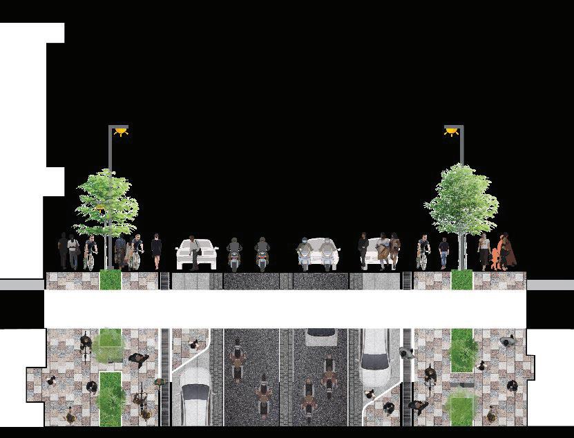
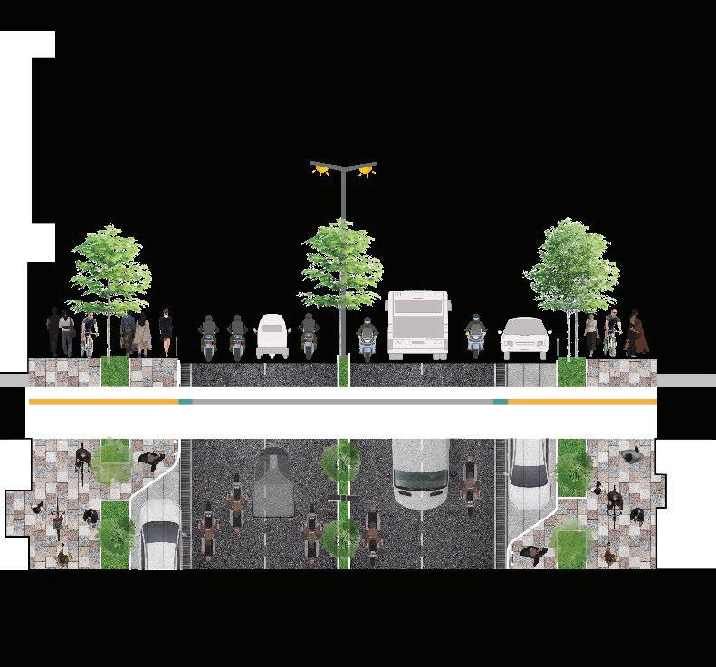
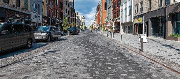
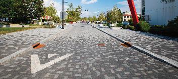
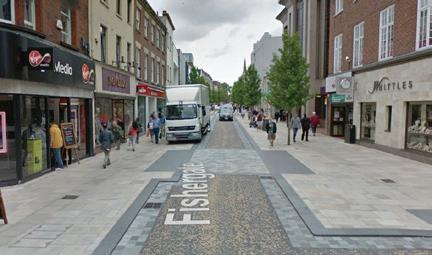
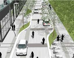
Multiple ways of creating Complete Streets exist - some that try to balance vehicle and pedestrian movement (Image on left shows 2-lane traffic movement in both directions and left over space is designated for a mix of walking and parking), whereas some that prioritizes pedestrian movement over vehicle movement (Image on right shows a wider footpath and building frontage zone and 2-lane undivided carriageway).
1 Road Safety in India Status Report 2023 by the Transportation Research and Injury Prevention Centre, IIT Delhi
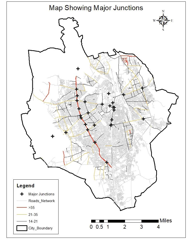
Rajkot is a small city with a mix of land uses with pockets of high population density. Rajkot’s principal industrial sectors are in the west, east and south, retail hubs in the centre, and institutional areas in the west. As one of the primary employment centres of the region, Rajkot experiences significant traffic flow from neighboring villages to its industrial sectors, retail hubs, and institutional areas.
The city’s street network, consisting of approximately 2000 km of highways, arterials, sub-arterials, collectors, and local streets, faces congestion due to inadequate traffic management and increasing numbers of registered vehicles, predominantly twowheelers. The city currently has about 180 cars and over 600 2-wheelers per 1000 people.
The Rajkot Municipal Transport Services (RMTS) runs buses along 49 routes with 502
bus stops. The city also has a BRT route 10.7 km long and is panning to add additional routes creating a 63.5km BRT network.
Despite considerably high private vehicle ownership, it is worth noting that 48% of trips in Rajkot are made by walking or cycling.
However footpaths are either not present in the city, or are encroached by vendors or parking.
RMC thus commits to undertake projects that will prepare the city for the future and create a balance between street use and street design through the support of the Complete Street Guidelines.
Street typologies are categorized based on two parameters; (1) capacity-based; and (2) demandbased.
(1) Capacity based parameters include consideration of the right-of-way (RoW) width, length, and desired speed of the street to function within the network. The main street typologies as per capacity-based parameters are similar to ones proposed by IRC:SP:118-2018:
• Arterial (includes urban expressways)
• Sub-arterial
• Collector
• Local streets
(2) Demand based parameters include consideration of the surrounding land uses, commuter or freight demand, and/or parking demand. These are subtypologies within the main street typologies and include a combination of the following land use, density and mode preference considertations:
• Neighbourhood/ retail/ mixed use/ institutional/ parkway
• High density/ high rise/ mid rise/ low density
• Transit priority/ freight corridor/ NMT pathways
Most streets in greenfield plans such as Town Planning Schemes (TPS) will only need to be assigned typologies based on capacity-based parameters. Demand-based parameters only govern the design of the street edges as the area develops over time.
The IRC:SP:118-2018 manual is the primary national-level code that provides guidance on urban street design and development.
The code recommends the following classification of urban roads and streets:
1. Urban Expressways
2. Arterial Road
3. Sub Arterial Road
4. Collector Street
5. Local Street
6. Non-Motorized Transport (NMT) Streets and Greenways.
The Rajkot Complete Street Design Program builds on thes road and street classifications, contextualizing it to the city’s needs.
The National Urban Transport Policy (NUTP) 2006 delineates core objectives to achieve its vision to bring “people” at the centre-stage of planning and transform cities into “engines of economic growth.” One of these core objectives is “Equitable allocation of road space.”
The NUTP 2006 states intent to “encourage measures that allocate road space on a more equitable basis, with people as its focus. This can be achieved by reserving lanes and corridors exclusively for public transport and non-motorized modes of travel. ”
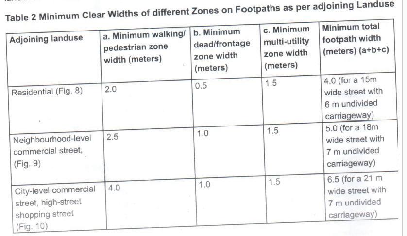
Figure 2. Source: IRC 103:2022: Guideline for Pedestrian Facilities
Allocating equitable road space requires an understanding of potential demand across the different modes. This is usually considered through an understanding of adjoining land uses. The allocation of space for pedestrian movement, for example is governed by the IRC 103:2022: Guideline for Pedestrian Facilities as shown in the table below.
Similarly, on streets with high transit demand, where public transport frequencies of more than 7 schedules per hour are desired and where traffic congestion leads to potential deterioriation of reliability or more than 20% schedule delays, bus lanes are advisable. Bus lanes should be segregated from common lanes through continuous lane markings and preferable physical segregation or CCTVs to encourage adherence.
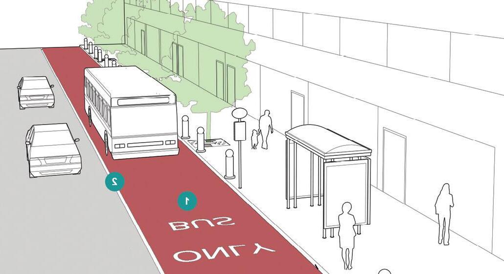
Figure 3. Curbside Bus Lane showing pavement markings for segregation| Source: NACTO Urban Street Design Guide
Global best practices in street design advise design coherence to be created through two types of elements; (1) Elements of Continuity; and (2) Elements of Differentiability. Together these elements create a uniform design language that influences feelings of reliability and coherence among users, while also allowing for flexibility to address changing needs.
(1) Elements of Continuity are those elements of a streetscape that must continue through its length, and are largely consistent across all streets of the same typology. Some of these overarching elements are shown here including their applications across various typologies, as presented in the Healthy Street Design Workbook - ITDP.
of
to prioritize the welltransport. This can be of 15 minutes or less.
Transport (NMT) plans zones, and efficient vehicles.
Right of Way (For Greenfield Development)
Segregated footpath
Segregated footpath
Segregated cycle track
Segregated cycle track
typology network. Based on streets are classified
movement of through traffic on speeds of upto 60kmph. between 30 - 50m. provides connection ROW width for a
to provide throughof upto 30Kmph.In a
Based on classified traffic on 60kmph. 50m. connection a through30Kmph.In a
Multi-Utility Zone (MUZ)*
Multi-Utility Zone (MUZ)*
On-street Parking
On-street Parking
At-grade crossings
At-grade crossings
Bus Stops
Bus Stops
Dedicated Bus Lanes
Dedicated Bus Lanes
Service Lane
Service Lane
Speed Limit
Speed Limit
Carriageway
Carriageway
Table 1: Street elements and their presence on Arterial, Collector and Local Streets Arterial Street Collector Street Local Street
Remarks
Remarks
Design speed to be 15kmph on RoW ≥9m with no footpath
Design speed to be 15kmph on RoW ≥9m with no footpath
Should be on streets with RoW
Should be in service lane if provided on arterial streets
Carriageway width should be maximum of 50% of the total Right of Way as per IRC:SP:118-2018
Carriageway width should be maximum of 50% of the total Right of Way as per IRC:SP:118-2018
Table 1: Street elements and their presence on Arterial, Collector and Local Streets
Should be present May be present
Figure 4. Elements of Continuity | Source: ITDP
Should be in service lane if provided on arterial streets *MUZ - It
Should not be present
(2) Elements of Differentiability are those elements that address the contextual needs at specific locations along the streetscape and create the necessary variations along a streetscape. For example, some parts of the streetscape may require placement of benches and shade, whereas other part of the streetscape may require vending spaces.
Elements of differentiability must be accommodated through a detailed design excercise requiring creation of General Arrangement Drawings - street plans showing lane definition and curb lines along with placement of parking, pick-up and drop off areas, tree pits, landscape verges, utility boxes or manholes, bus stops, street lights, signal poles, signage posts, crossings, refuge islands, etc.
This Complete Streets Guide only provides guidance for ‘Elements of Continuity.’ RMC will engage urban designers from time to develop street plans that also accommodate the necessary elements of differentiability.
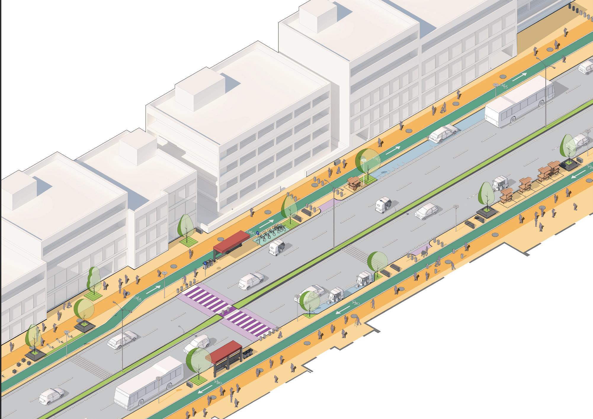
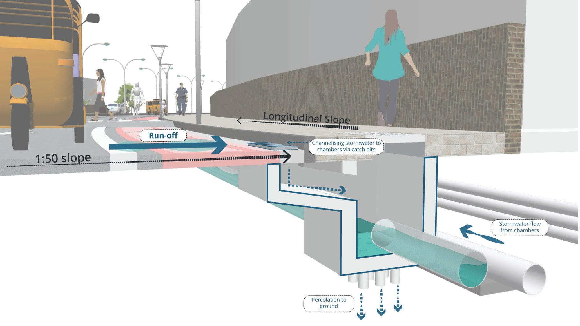
For complete streets to function to their full potential, it is important to plan utilities in an integrated manner, as far as possible making space for them underground.
The most critical utilities to be planned under streets are:
1. Water Supply and Gas Line
a) These are places closest to the building edge or coumpound walls to ease direct connections to adjoining buildings.
b) Coordination required with Water Supply Board and Gas Distribution Company respectively
2. Power and Telecommunication
a) These can be located anywhere under the street edge. Flexible HDPE pipes are recommended that can be navigated around obstacles and chambers.
b) Well-marked manholes are recommended every 120 meters.
c) Coordination required with Power Distribution Company and Telecommunication Company.
3. Sewage Management
a) Sewage pipes should be placed away from water supply pipes and at the lowest level to prevent leakage into water supply or storm water lines.
b) Manholes for smaller sewers (max dia- 30cm) can be spaced at 30m.
c) Coordination required with Sewerage Board.
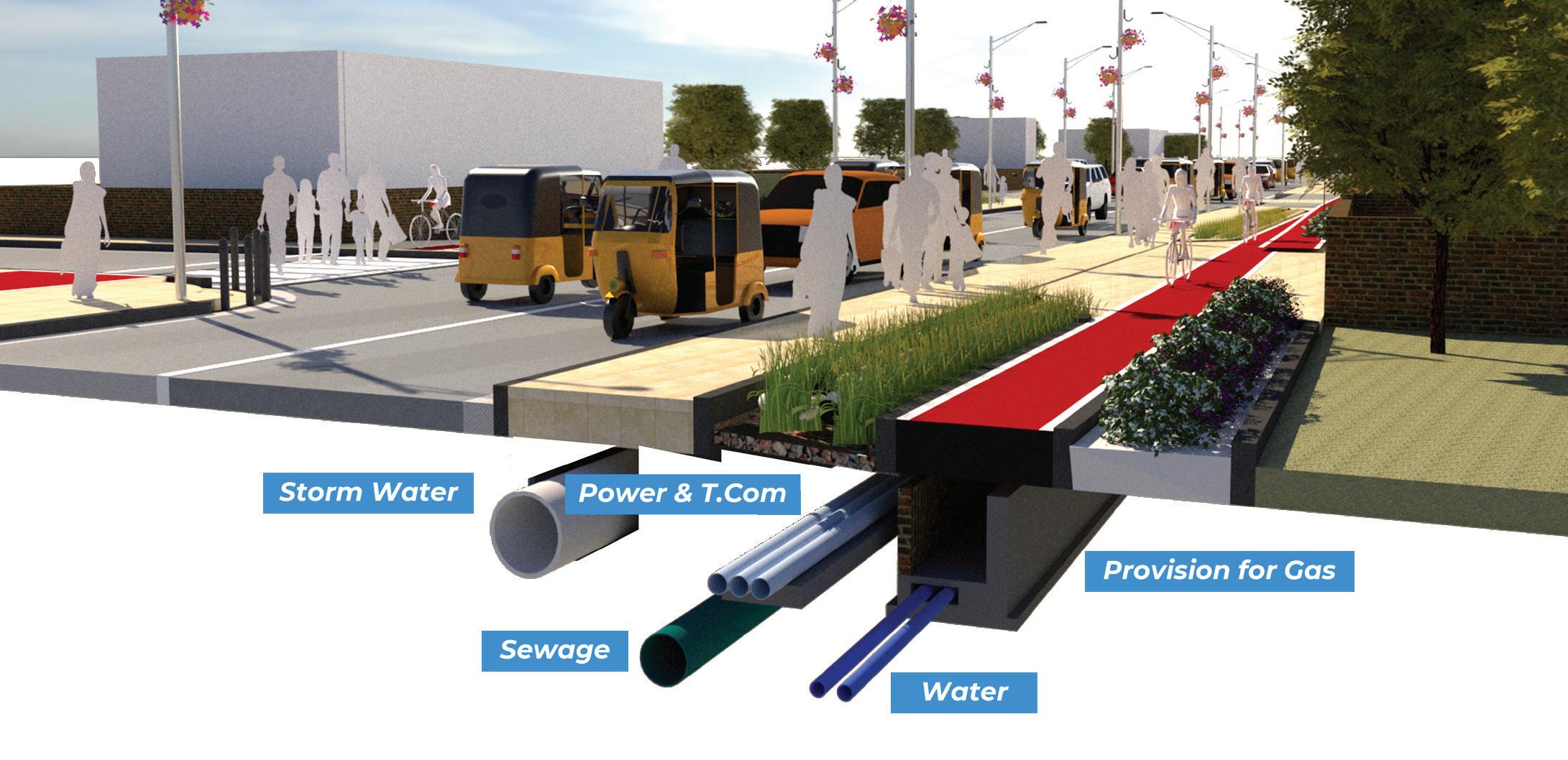
a) Storm water is one of the most essential elements of any street. Storm water management infrastructure is usually located abutting the carriageway for efficient draining of water and to ensure limited cross overs
b) There are multiple ways to manage storm water, depending on the volume of rain received and the space available on a street.
c) Wider streets, where sufficient width is available, may provide bio-swales, which are natural drains covered with grasses, that help slow percolation of water into the earth.
i. Compact urban roads will need to provide either box drains or piped drains.
d) Hybrid natural and piped drains can also be provided, as shown below, to ensure sustainability and resilience of streets.
e) Manholes should be provided every 80-100m for regular cleaning and maintenance of storm water drains.
These Guidelines are developed with the principal understanding that all streets are not the same but they share certain characteristics that can make it easy for designs to be developed and replicated. To enable such replication across the city, it is important to understand the various types of streets that exist in Rajkot and how they can be categorized into a smaller set of street typologies. For each street typologies then, the intent is to develop typical guidelines that can ease the process of planning and design.
A comprehensive look at the logic of defining the street categories is shown below.
Figure 8. Diagrammatic illustration of ideal RoW forr each street typology
Mixed use shared street
Informal pathways
Mid-rise mixed use
Low density
High rise residential
Mixed use high density
High streets - retail destinations
Institutional/ passive
Promenades/ parkways
4. Para Bazar Road – 3-6 m
5. Pramila Nagar road – 3-6 m
6. Lakhaji raj Street –9m
7. Ashapura Road -9m
8. Chandan park road – 9m
9. Jay Sardar Road –12m
10. Canal Road – 12m
11. Panchavati Main Road – 15 m
12. Shital Park Road –18 m
13. Tagore Road -18 m
14. 80 Feet Road –24m
15. Nana Mava Road -24m
16. Bhavnagar road–24m
17. Kalavad Road –30m
Arterial roads are major thoroughfares that connect to intercity highways and connect different city zones. They are designed for continuity and offering highest capacity and high-speed movement. They typically have multiple lanes and limited access points, and vehicular movement is prioritized over other modes. Within a city’s road network, they must be spaced between 1.5km to 3km apart.
Typical Width: 36m or more
Sub- typologies:
1. Transit Priority Corridor: should be planned along arterial roads where high frequency bus routes are required to be run. For example, 150 Feet ring road, Yagnik roads are ideal as Transit Priority Corridors. These corridors should be designed to prioritize public transportation systems, enhancing efficiency and accessibility while accommodating other vehicle types.
2. Freight + Vehicle Mobility Corridor: are designed to facilitate the efficient movement of all types of vehicles, including trucks and regular passenger traffic, supporting the city’s economic activities.
36m wide street with BRT corridor
It is well-suited for arterial streets, major urban corridors with high-intensity traffic. It prioritizes efficient public transportation and non-motorized travel
Figure 9. Section and Plan showing an ideal Arterial road design; Source: Healthy Streets Design Workbook, ITDP.
45m wide street with segregated cycle tracks
This template is well suited for arterial streets. Metro station entrances should be planned ensuring unobstructed clear walking zone of minimum 2m.
Tree pit with seating
Tree pit level ±0.00mm
Staircase location level ±0.00mm
Lift Location level ±0.00mm
Speed hump
Street Light
Tree pit grating level +150mm
BRTS cycle track 1-side parking parking footpath two way shared street pedestrian-only median service lane
(60-80m)
Distributor/Collector Road (12-30m)
(6-15m)
1. Arterial Road (50km/hr)
2. Sub-arterial Road (50km/hr)
3. Distributor/Collector Road (30km/hr)
4. Access Streets (15km/hr) local km/h), for a for movement and 4.5 movement
5. Lane Configuration
a) Number of Lanes: Consider the carrying capacity needs as suggested in IRC:106-1990 Table 2 to determine lane configuration.
b) Lane Width: Each lane should have a width of 33.5m to accommodate various vehicle types while maintaining safe driving conditions (Global Street Design Guide). The minimum widths for two and three lanes should be 6m and 8.5m, respectively, in each direction (Bhubaneswar Street Design Guidelines).
6. Access Management
3 - 3.5m
Figure 10. No of lanes and lane width; Source: Bhubaneswar Street Design Guidelines, BDA
Well-designed service lanes improve safety and throughput of the carriageway by segregating property access points and parking from the main carriageway.
a) Limited Access Points: Minimize direct access points to maintain traffic flow and safety. Limit access to intersections and designated entry/exit points.
b) Service Roads on roads with RoW > 45m:
In local streets that need to accommodate buses and trucks, the width of a two-way carriageway can vary between 6 and 6.5 m, depending on the volume of heavy vehicles (ITDP, 2011).
In a collector street, the optimum width for the carriageway is 5.5 m per direction (ITDP, 2011).
Wide service lanes also invite encroachment by shops, parked vehicles, or street vendors. challenges
Service lanes that are wide enough for two-way car movements encourage speeding and wrong-side driving, thus defeating one of their primary roles: to provide safe pedestrian space.
ii. Incorporate service roads where necessary to allow for local access without disrupting arterial flow. Service lanes adjacent to active commercial edges should be located on the outer edge of the footpath (Bhubaneswar Street Design Guidelines).
In arterial streets, the optimum widths for two and three implied lanes are 6 m and 8.5 m, respectively, in each direction. When considering carriageways wider than 6 m per direction, one should keep in mind that they easily lead to excessive speeds, wrong-way driving, and encroachments such as parking (ITDP, 2011).
design recommendations
iii. A minimum lane width of 3.0m is recommended for each lane. If heavy vehicles are anticipated, lanes should be increased to 3.5m (Bhubaneswar Street Design Guidelines).
Access to service lanes should be provided at midblocks; service lanes should never start or end at an intersection
Figure 11. Access to service lane Source: Complete Streets Design Workbook, ITDP
criteria for a service lane
Bhubaneswar Development Authority
A service lane can be considered on a high volume arterial road of sufficient width and with high speed traffic if the following criteria are met. i. property access points more than once every 15 m and/or ii. active edge A service lane should be 3
Figure 12. Width of the service lane for Arterial roads Source: Complete Streets Design Workbook, ITDP
7. Traffic Management
recommended in speeds and also presence of the adjacent greater; 4m pedestrian crossing accordance with IRC 103 adjacent 0.15m) with slope in the parking crossings to reduce recommendations flow of erect barriers prevent pedestrians intervals. tend to jump over becoming prone often indicated markings. Such provide any pedestrians. crossings allow streets safely
a) Speed Limits: Establish a standard speed limit of 60-80 km/h depending on the area (residential, commercial, etc.).
b) Intelligent Traffic Management: Implement intelligent and adaptive traffic signal systems to optimize traffic flow.
8. Grade-separated facilities:
a) Flyovers at intersections: can be considered only if signal cycle lengths required to manage traffic go beyond 2mins or 120 seconds.
b) Flyovers for link augmentation: are not preferred and should be considered only if traffic disruption is simulated up to a 2km distance around the link and is seen to be minimal.
9. Crossings:
a) Zebra crossings of minimum 2m or as wide as the adjacent footpath, whichever is greater; 4m in areas of high pedestrian crossing movements, in accordance with IRC 103 should be marked at regular intervals along arterial roads. These crossings should be marked with high-visibility paint and may be raised or textured to enhance pedestrian safety.
b) Refuge islands of minimum 1.2m width and 3m length should be provided when total crossing distance is more than 10m.
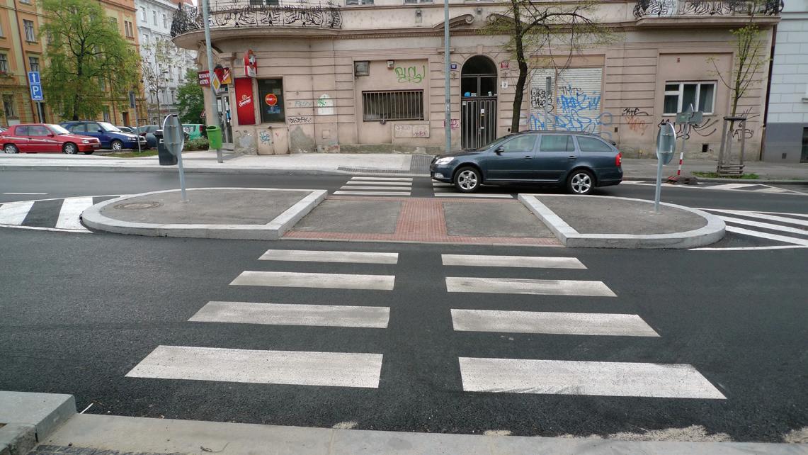
c) Traffic islands, where existing, must accommodate 1.5m of pedestrian walkways to ease crossing to the different street arms connecting at the intersection. Sculptures, if provided on traffic islands, should be placed to not disturb pedestrian movement safety.
Crossings should be such that there is minimum deviation from the path of travel defined by the pedestrian zone in the footpath (pedestrian desire line).
1. Foot paths:
a) Need to be segregated, must have kerb height of 100 –150mm.
b) Must have a minimum width of 2.5 meters.
c) Surface should be levelled and continuous through use of footpath ramps for wheelchairs and ramps at plot entry and exits. Ramp slopes should not exceed 1:12.
d) Stamped concrete or rectangular paver blocks are preferred. Special areas may also have stone pavers.
2. Multi Utility Zones (MUZ):
a) Pedestrian lighting with poles of 8-12 m height should be placed at 10-15m distance and should throw light at footpaths.
b) Landscaping strip should be a continuous strip of minimum 1.2m width and 1.2m length and may include trees and/or heat and drought-resistant grasses. Trees should be of the shade-giving variety but maintain vertical clearance of 2.4m.
c) Amenity zones of 1.2m x 3m must be planned along footpath edges and must include benches, trash bins, emergency call phones and cycle parking stands.
3. Dedicated Cycle tracks:
a) Segregated cycle tracks should be provided between the carriageway and footpath and should be separated by a kerb or bollards.





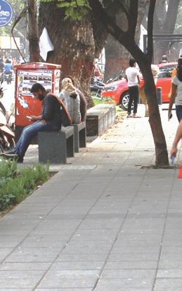
Physically segregated cycle tracks ensure safety and reduce the possibility of encroachment by moving motor vehicles and parking. Cycle tracks should be continuous, with smooth turnings to allow uninterrupted movement and well-shaded & well-lit to provide comfort and safety. Cycle tracks should be planned in a network rather than in isolated parts to ensure seamless connectivity across the neighbourhoods.
Physically segregated cycle tracks
b) Cycle tracks should have a minimum width of 2.0 meters for one-way and 3.0 meters for two-way tracks. This ensures sufficient space for cyclists to maneuver safely.
Physically segregated cycle tracks are recommended for streets with predominantly speeds exceeding 30 km/h to enhance cyclist safety.
Physically segregated cycle tracks
c) Cycle track surface should be coloured asphalt or stained concrete.
Cycle tracks at footpath level are recommended to prevent encroachment by moving vehicles and parking. At footpath level
Physically segregated cycle tracks are recommended for streets with predominantly speeds exceeding 30 km/h to enhance cyclist safety.
d) At intersections, road markings should be provided to guide cyclists moving in all directions.
4. On-street Parking:
Physically segregated cycle tracks ensure safety and reduce the possibility of encroachment by moving motor vehicles and parking. Cycle tracks should be continuous, with smooth turnings to allow uninterrupted movement and well-shaded & well-lit to provide comfort and safety. Cycle tracks should be planned in a network rather than in isolated parts to ensure seamless connectivity across the neighbourhoods.
Painted cycle lanes
a) On street parking should only be provided in service roads and never on the main arterial carriageway.
Figure 16. Arrangement of footpath, landscape strip and amenities in a MUZ. Source: Healthy Streets Design Workbook, ITDP
Cycle tracks at footpath level are recommended to prevent encroachment by moving vehicles and parking.
These can be provided while testing new designs on existing streets. Painted cycle lanes, however, are prone to encroachment by moving vehicles, vending, parking. Hence it is recommended that the parking space and vending is well-defined.
Painted cycle lanes
b) On-street parking spaces should have standard dimensions, with parallel parking spaces measuring 2.4 meters in width and 5.0 meters in length.
These can be provided while testing new designs on existing streets. Painted cycle lanes, however, are prone to encroachment by moving vehicles, vending, parking. Hence it is recommended that the parking space and vending is well-defined.
c) On street parking should not be provided at street corners; rather kerb extensions should be provided to clearly demarcate defined space for parking.
d) Time-limited parking should be implemented to encourage turnover in high-demand areas, typically set for 1-2 hours. Clear signage must be installed to mark parking spaces, indicating time limits, parking rules, and enforcement information.
In streets with parking along cycle track, a buffer of minimum 0.5m should be provided to protect the cyclists from dooring. In other cases, only a kerb (0.15m wide )may be used as a buffer to save space.
In streets with parking along cycle track, a buffer of minimum 0.5m should be provided to protect the cyclists from dooring. In other cases, only a kerb (0.15m wide )may be used as a buffer to save space.
At carriageway level
0.0mm
Cycle tracks at road level have lower construction and maintenance costs, but they may not be universally accessible to wheelchair users when crossing from the sidewalk to the road due to the level difference.
Figure 17. Cycle track at footpath level (above) and at carrageway level (below). Source: Healthy Streets Design Workbook, ITDP
At carriageway level
Points to note
Cycle tracks at road level have lower construction and maintenance costs, but they may not be universally accessible to wheelchair users when
Cycle tracks should be clearly demarcated using paint & signage, especially at intersections and property entrances to deter motor vehicle encroachment.To prevent pedestrians from using cycle tracks, ensure there is a clear and unobstructed walking space.
1. Storm water Drainage:
To ensure that project implementation is directed towards desired outcomes; and successes, failures and benefits are monitored and evaluated, a checklist is prepared to evaluate applications for street design essentially for new roads or for cases where the entire street is revamped. This checklist is not intended to alter or infringe the design standards, but is consolidated minimum standards that should be followed for developing and preserving safe operations of road facility. Following is a checklist categorized in three layers: A) Underground; B) Footpath; C) Cycle Tracks; D) Intersections; and E)
Above-ground Utilities
a) Storm water drains must be provided on both sides of the road, under the amenity or parking strip.
b) FRP grates must be fixed at drain openings to prevent solid waste from flowing into drains.
c) The bottom level of the drain must be as per the gradient of the underground drainage system and must not be fixed as per the road surface level.
The following section outlines the utility design requirements for the installation of underground services. To initiate a complete street design for a greenfield or retrofit development, underground layer should be implemented as a first layer complying with the minimum requirements outlined in the section below:
d) The minimum spacing of manholes varies from 30 m for smaller sewer dia to 300 m for sewers above 2000 mm dia. Refer to National Capital Regional Board Masterplan Toolkits.
2. Water Supply and Sewage Pipes:
Element Responsibility Features YES NO NA
Sewer/ Drainage Lines
Water Supply Lines
a) Sewage lines are to be laid at a substantial depth below grade and ideally located away from water and rainwater drainage networks to avoid accidental contamination. (TenderSure Guidelines, Jana USP)
Electricity Cables
Telecommunication Cables
Recommended depth: 2.0-6.0m for a Trunk Sewer Line
Recommended depth: 0.6-1.0 m for a service line 1.0-1.5m for a trunk line
b) Sewer and drain lines are to be laid at an appropriate incline that encourages gravitational flow from local to trunk lines within the networked hierarchy. (TenderSure Guidelines, Jana USP)
Gas Pipelines
Recommended depth: 0.6-1.0m for low tension cable 1.5-2.0m for high tension cable
Recommended depth: 0.6-1.0m directly laid
Recommended depth: 2.0-3.0m
The placement of the utilities should comply with the below schematic representation, following the depth as per the above table:
c) Water lines are maintained under pressure and are to be laid away from the road traffic areas so as to avoid damage to the surface due to any leakages. (TenderSure Guidelines, Jana USP)
d) The Indian Roads Congress (IRC: 98-1988) recommends a depth between 2.0 m to 6.0 m for a ‘trunk sewer line’ and a depth of 1.0 m to 1.5 m for a ‘trunk water line’ and 0.6 m to 1.0 m for ‘service water line’.
3. Gas, Electricity and Fiber Conduit:
a) Individual conduits to be provided for gas, electricity and fiber lines below the footpath, closest to the plot boundaries. (TenderSure Guidelines, Jana USP)
To ensure that project implementation is directed towards desired outcomes; and successes, failures and benefits are monitored and evaluated, a checklist is prepared to evaluate applications for street design essentially for new roads or for cases where the entire street is revamped. This checklist is not intended to alter or infringe the design standards, but is consolidated minimum standards that should be followed for developing and preserving safe operations of road facility. Following is a checklist categorized in three layers: A) Underground; B) Footpath; C) Cycle Tracks; D) Intersections; and E) Above-ground Utilities
b) Pipes carrying combustible materials such as gas should be located far away from electricity cables and sources of heat. The Indian Roads Congress (IRC) recommends laying of such pipe lines at a depth of 2.0-3.0 m. (TenderSure Guidelines, Jana USP)
c) Gas lines should not be laid parallel to High Tension (HT) lines. (TenderSure Guidelines, Jana USP)
The following section outlines the utility design requirements for the installation of underground services. To initiate a complete street design for a greenfield or retrofit development, underground layer should be implemented as a first layer complying with the minimum requirements outlined in the section below:
ELEC: Electricity Cable SWD: Sewerage/Drainage & Water Lines SEW: Sewerage
Element Responsibility Features YES NO NA
Sewer/ Drainage Lines
Water Supply Lines
Electricity Cables
Telecommunication Cables
Gas Pipelines
Recommended depth: 2.0-6.0m for a Trunk Sewer Line
Recommended depth: 0.6-1.0 m for a service line 1.0-1.5m for a trunk line
Recommended depth: 0.6-1.0m for low tension cable 1.5-2.0m for high tension cable
Recommended depth: 0.6-1.0m directly laid
Recommended depth: 2.0-3.0m
The placement of the utilities should comply with the below schematic representation, following the depth as per the above table:
Figure 18. Placement of the utilities, Source: Bhubaneswar Street Design Guidelines, BDA
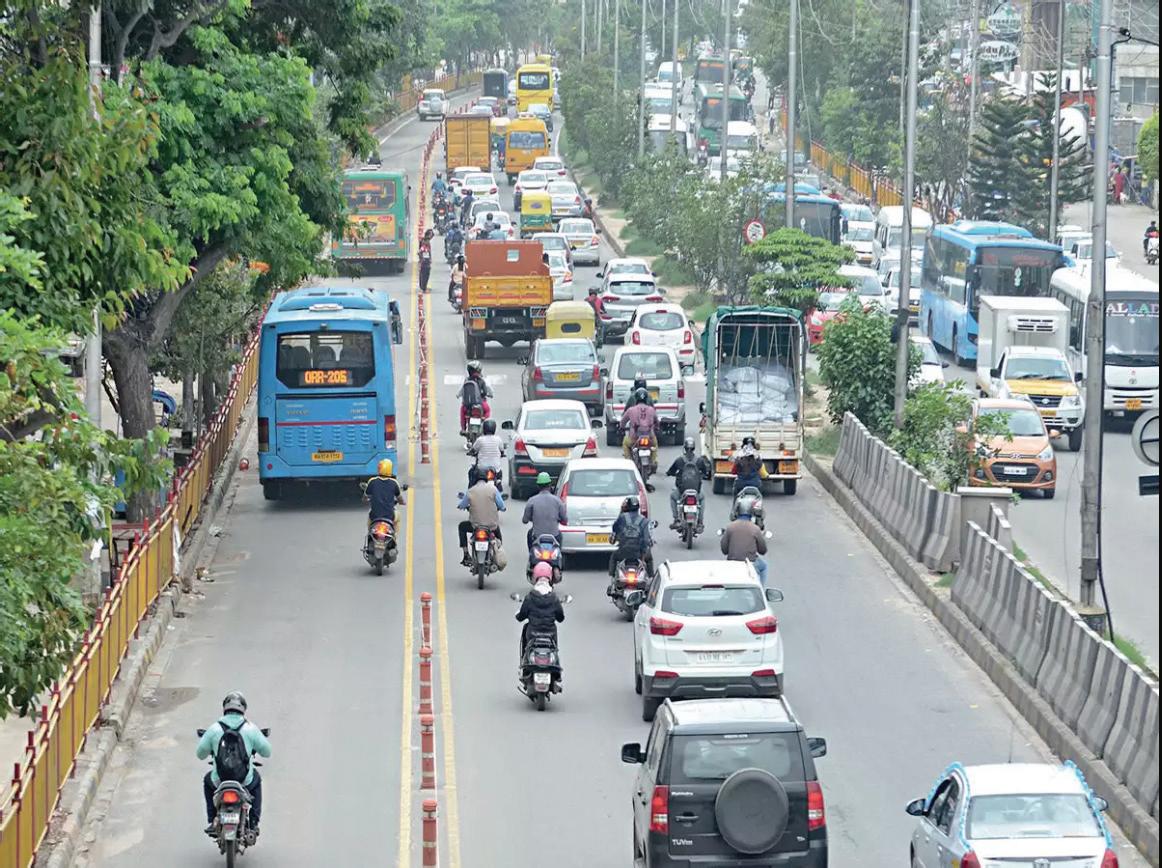
1. Dedicated Bus Lanes: Implement dedicated bus lanes with a width of 3.5m, separated from general traffic lanes to ensure uninterrupted public transport (ITDP India Street Design Manual).
2. Transit Signal Priority: Where bus lanes cannot be provided, incorporate ITMS systems that give transit vehicles priority at traffic signals to minimize delays.
3. Bus Stops Bus stops must be located atleast 25 m away from any major intersection, preferably before the junction. Bus stops may be located after the junction if they are likely to cause congestion for left turning traffic.
2.1.4 Bus Stops
4. Bus Shelters: Provide shelters at all bus stops to enhance rider comfort (Global Street Design Guide) without encroaching on the clear footpath space required.
Bus stops provide safe and comfortable waiting spaces. They should be located such that they are easy to identify and do not obstruct the walking zone. Bus stops should be placed such that buses can pullover in their original path and do not need to get into a niche (bus bay), thus ensuring smooth movement of traffic. A typical bus stop shelter should be 9mx2.5m in size. The length of the bus stop should be determined based on the number of buses and expected volume of buses using the stop. For seamless multi-modal integration, relocate the existing bus stops wherever necessary to the nearest public transport interchange options. Ensure the placement of new bus shelters in closer proximity to other modes of public transport.
5. Bus Bays: Where dedicated bus lanes cannot be provided, design bus bays that are at least 30m long and located at the curb to avoid obstructing traffic.
6. Information Signage: Install signs 50 m on either side of the bus stops to show direction to bus stops; and bus network maps and area maps at bus stops.
7. Pedestrian Crossing: Pedestrian crossings must be provided within 50m of a bus stop, including refuge islands, if necessary, for mid block crossings.
8. Ensure continuous footpaths and cycle tracks by diverting them behind the stop

Figure 19. Dedicated Bus Lane in Bangalore; Source: Wikimedia Commons


Bus stops should be easy to locate, and should display information maps, up-to-date route number, direction of travel, major stops and helpline perpendicular to pedestrian movement on footpaths>4.5m wide and parallel to pedestrian movement on footpaths <4.5m wide
Bus stops should be at the same level as footpaths, and railings should not be provided along the kerb edge, as it obstructs the lighting path. In cases where the bus stand’s elevation is not on the same level from the walkway or pathway, it is recommended to have two separate ramps for boarding and alighting. There
Figure 20. Bus Bay and Bus stop design specifications; Healthy Streets Design Workbook, ITDP
Vehicle Priority Corridors are designed to facilitate the efficient movement of all types of vehicles, including trucks and regular passenger traffic, supporting the city’s economic activities.
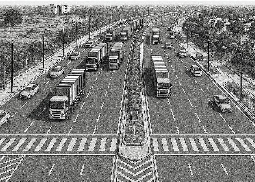
1. Heavy Vehicle Accommodation: To minimize conflicts with passenger vehicles, include wider lanes (minimum 3.5m) and a separate lane for freight vehicles (Global Street Design Guide).
2. Designated Turn Lanes: Provide dedicated turn lanes at intersections to allow for smoother traffic flow.
3. Service Lanes: Plan service lanes along the corridor where loading and unloading or stopping is required, ensuring these zones are clearly marked and do not obstruct traffic flow.
4. Zebra Crossings: Construct high-visibility zebra crossings at all intersections and all crossing locations.
Sub-arterial roads serve as intermediate routes between arterial and collector streets. They carry moderate volumes of traffic and often connect neighborhoods or important destinations with arterial roads. Sub-arterial roads must be spaced 1km to 4km apart within the street network.
Typical Width: 24 to 45 meters
Types of Sub-arterial roads:
1. Mixed-Use High Density sub-arterial roads are designed to support a combination of residential, commercial, and recreational activities.
2. High Streets - Retail Destinations serve as key retail corridors that attract significant foot traffic and support local businesses.
3. Institutional – Passive in nature fronting large school or college campuses, hospitals, or government facilities.
4. Promenades/Parkways front natural areas such as lakes or open spaces and are best used for recreational activities, walking, and cycling.
Figure 22. Section and Plan showing an ideal Subarterial road design; Source: Healthy Streets Design Workbook, ITDP.
30m wide street with segregated Cycle tracks
The template excels in arterial streets of mixeduse areas where urban vibrancy is vital, such as city centers, commercial districts, and neighborhoods with significant pedestrian footfall.
Service lane should be designed as a discontinuous lane with entry and exit, to avoid its usage as another carriageway.
1. Lane Configuration
a) Number of Lanes: Consider the carrying capacity needs as suggested in IRC:106-1990 Table 2 to determine lane configuration.
b) Lane Width:. Sub-arterial road lanes should have a standard width of 3.0m to 3.5m.
2. Access Management
a) Vehicle access to properties along sub-arterial roads must be either avoided or strategically combined to reduce disruptions to traffic flow. Access to residential and commercial properties should be clearly marked and conveniently located.
b) Service roads should be provided to allow local and segregated access to high vehicle traffic destinations such as malls or large scale mixed-use complexes.
c) A minimum lane width of 3.0m is recommended for service roads. If heavy vehicles are anticipated, lanes should be increased to 3.5m (Bhubaneswar Street Design Guidelines)
3. Traffic Management
volume arterial road of sufficient width and with high
a) Speed Limits: Sub-arterial roads can be designed for speeds of 40-60 km/h.
Service lane width : Min 3 m
Lane width 3 - 3.5m
Figure 23. Illustration representing Lane design specifications; Complete Streets Design Workbook, ITDP
m and/or
b) Intelligent Traffic Management: Implement intelligent and adaptive traffic signal systems to optimize traffic flow.
parking. The tight width discourages fast driving.
4. Intersections and Crossings
a) Signalized Intersection: The intersection of a sub-arterial road with an arterial or collector street or with any road of 4 lanes or more must be designed as a signalized intersection.
b) Zebra crossings of upto 3m width should be marked at all intersections and at a minimum spacing of 250 to 500m.
c) Refuge islands of minimum 1.2m width and 3m length should be provided when total crossing distance is more than 10m.
active street frontage
In areas with a porous boundary between the street and private properties, footpath should be located at the edge of the RoW.
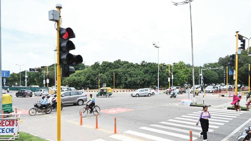
24. Image representing Signalized Intersection and crossings in an Indian city
In case lane should edge and inactive
1. Footpath:
a) Need to be segregated, must have a kerb height of 0.15 m.
Clear width of the pedestrian zone in a highintensity commercial area should be atleast 4m to accommodate high footfall.
Clear width of the pedestrian zone in a commercial area should be atleast 2.5m. commercial
b) Must have a minimum clear walking width of 4.0 m to 2.0 m depending on the commercial activity and footfall.
c) Surface should be levelled and continuous through use of footpath ramps for wheelchairs and ramps at plot entry and exits. Footpath should continue across property entrances with 0.6m wide vehicle access ramp along the edge. Where there is not enough width for an entrance ramp, footpath should slope gradually (< 1:12) to reach ground level at property entrances for wheelchair users.
narrow streets residential
Clear width of the pedestrian zone in a residential area should be a minimum of 1.8m for two wheelchairs to pass each other.
In narrow streets, MUZ can be optional or provided as discontinuous patches.
d) Stamped concrete or rectangular paver blocks are preferred. Special areas may also have stone pavers.
promote safe and pedestrian mobility. They all users including elderly and the Good footpaths primary public space of people can sit, meet, talk
the primary public space of people can sit, meet, talk
Figure 25. Illustration representing Footpath design specifications for a sub-arterial road; Complete Streets Design Workbook, ITDP
Multi-utility zone (MUZ) Frontage/ Dead zone Pedestrian zone
after creating the parking is usually footpath. Utilities to walking. Even with width, a footpath may be is not continuous or high kerb heights and
left over after creating the and parking is usually as the footpath. Utilities obstacles to walking. Even with width, a footpath may be use if it is not continuous or with high kerb heights and footpaths promote safe and pedestrian mobility. They accessible to all users including children, elderly and the differently-abled. Good footpaths
recommendations
zone: Continuous walking of any obstructions; at least
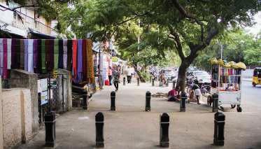
Frontage/dead zone: Provides a buffer pedestrian zone and the edge zone (MUZ): Space for street furniture, landscape, and property access ramps; size of MUZ depend on the footpath
Footpaths should be 0.15m high (top of kerb should be at 0.15m) so that they aren't surmountable for vehicles.
2. Multi Utility Zone (MUZ):
Footpaths should have adequate gradient for surface runoff. gradient
a) Pedestrian lighting with poles of 8-12 m height should be placed at 10-15m distance and should throw light at footpaths.
surface
Surface of the footpath should be of a tough, anti-skid material to ensure usability and safety in all weather conditions.
multi-utility zone (MUZ)
b) Landscaping strip should be a continuous strip of minimum 1.2m width and 1.2m length and may include trees and/or heat and drought-resistant grasses. Trees should be of the shade-giving variety but maintain vertical clearance of 2.4m.
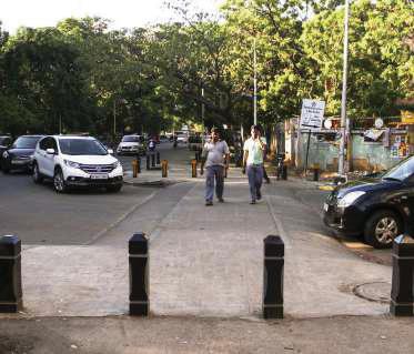
tree gratings
Surmountable gratings, with holes that are perpendicular to the movement of wheels of a wheelchair, should be used over tree pits to increase the effective width of the footpath.
c) Multi Utility Zone of 1.2m x 3m (in addition to the 2m walking width) must be planned along footpath edges and must include benches, trash bins, emergency call phones and cycle parking stands.
3. Dedicated Cycle tracks:
a) Where more than 4m edge is available, segregated cycle tracks should be provided between the carriageway and footpath and should be separated by a kerb or bollards.
b) Where the width of the edge is up to 4m, cycle lanes should be provided at the same level and continuous with the footpath.
c) Cycle tracks or lanes should have a minimum width of 1.5 meters for one-way and 2.5 meters for two-way tracks.
d) Cycle track or lane surface should be coloured asphalt or stained concrete.
e) At intersections, road markings should be provided to guide cyclists moving in all directions.
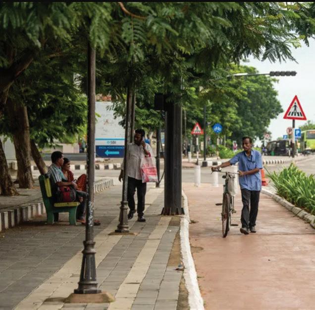
Figure 26. Image of Janpath Street, Bhubaneswar showing Multi-Utility Zone and a dedicated cycle track as part of the street design
enforcement ensures discipline.
4. On-street Parking
a) No on-street parking should be provided on subarterials, rather only waiting spaces and autorickshaw/ taxi queuing spaces may be provided.
b) Waiting/ queuing spaces for cars should have standard dimensions, with parallel spaces measuring 2 m in width and 6.0 m in length. For two-wheelers a 1.2 m
c) Waiting/queuing spaces should not be provided at street corners; rather kerb extensions should be provided to clearly demarcate defined space for waiting vehicles.
d) Dedicated cycle parking should be provided at public transport stops and stations and in commercial areas, to facilitate multi-modal integration.
1. Storm water Drainage:
Orientation
Figure 27. Illustration showing dedicated cycle parking design specifications; Healthy Streets Design Workbook, ITDP
Parallel parking is recommended on streets where parking is essential. precious street space for public flexibility to accommodate perpendicular wheeler parking as well.
Integrate bulb-outs into parking car parks (approximately 30m) pedestrian lights, utility boxes, furniture without interruption.
cycle parking should at public transport stops and commercial areas, to facilitate integration.
a) Storm water drains must be provided on both sides of the road, under the amenity or parking strip.
b) FRP grates must be fixed at drain openings to prevent solid waste from flowing into drains.
c) The bottom level of the drain must be as per the gradient of the underground drainage system and must not be fixed as per the road surface level.
d) Stormwater drains should be sized appropriately for medium traffic roads, typically with 400600 mm diameter pipes, depending on the area’s rainfall intensity and runoff requirements. The spacing between manholes should generally be around 30-50 meters, but this may vary based on the terrain and expected stormwater volume.
*Refer Table 1: Street elements and their presence on Arterial, Collector and Local Streets
2. Water Supply and Sewage Pipes:
a) Water Supply Infrastructure: For sub-arterial streets, the water supply pipeline network should cater to medium-density urban areas. Pipes typically in the range of 250-400 mm in diameter are sufficient for handling the distribution of water to surrounding neighborhoods and businesses. The water network should be designed to minimize water loss and ensure easy access for maintenance and repairs.
b) Sewage and Wastewater Management: The sewage system for sub-arterial streets should be designed with gravity flow principles in mind to minimize reliance on pumping stations. Sewer pipes ranging from 300 mm to 600 mm in diameter can be used depending on the population density served. Manhole spacing for these streets typically ranges from 30 meters to 50 meters, depending on the size of the pipes and the street design.
c) Public Sanitation: Public toilets or sanitation facilities should be provided along sub-arterial streets in high-density areas or places with heavy foot traffic. These restrooms should be connected to the main sewage system to ensure proper waste disposal and prevent sanitation issues.
d) Integration with Main Sewer Network: Ensure that all sub-arterial street sewage lines are seamlessly integrated into the larger municipal sewage treatment network. The design should anticipate future urban growth and include provisions for potential expansions or upgrades.
The following section outlines the utility design requirements for the installation of underground services. To initiate a complete street design for a greenfield or retrofit development, underground layer should be implemented as a first layer complying with the minimum requirements outlined in the
Element Responsibility Features YES NO NA
Sewer/ Drainage Lines
Recommended depth: 2.0-6.0m for a Trunk Sewer Line
Water Supply Lines
The following section outlines the utility design requirements for the installation of underground services. To initiate a complete street design for a greenfield or retrofit development, underground layer should be implemented as a first layer complying with the minimum requirements outlined in the section below:
Electricity Cables
Recommended depth: 0.6-1.0 m for a service line 1.0-1.5m for a trunk line
Recommended depth: 0.6-1.0m for low tension cable
1.5-2.0m for high tension cable
Element Responsibility Features YES
Sewer/ Drainage Lines
Telecommunication Cables
Water Supply Lines
Gas Pipelines
a) Underground Utility Networks: Similar to collector streets, sub-arterial streets should feature underground utility networks to minimize street clutter and maximize space for pedestrians and vehicles. Utilities such as gas pipelines, electricity lines, and fiber optic cables should be laid in the same trench (where possible) to reduce excavation and maintenance costs. The pipelines and cables should be well-spaced for safety.
Electricity Cables
Recommended depth: 2.0-6.0m for a Trunk Sewer Line
Recommended depth: 0.6-1.0m directly laid
Recommended depth: 2.0-3.0m
Recommended depth: 0.6-1.0 m for a service line 1.0-1.5m for a trunk line
The placement of the utilities should comply with the below schematic representation, following the depth as per the above table:
Recommended depth: 0.6-1.0m for low tension cable 1.5-2.0m for high tension cable
b) Utility Access Points: Ensure utility access points for gas, electricity, and fiber optics are installed in safe, clearly marked locations along sub-arterial streets. These should be easily accessible for maintenance work without disrupting traffic or pedestrian movement.
Telecommunication Cables
Gas Pipelines
Recommended depth: 0.6-1.0m directly laid
Recommended depth: 2.0-3.0m
The placement of the utilities should comply with the below schematic representation, following the depth as per the above table:
c) Service Connections: Provide sufficient capacity for future service connections, particularly for fiber optic networks and electric vehicle (EV) charging stations. Consider leaving space in ducts for future technologies or smart infrastructure, like smart street lighting and public Wi-Fi networks.
d) Safety Standards: Ensure that gas pipelines are placed at a safe distance from other utilities, particularly high-voltage electricity lines. Adequate clearance between different utility lines is crucial to avoid cross-interference and to comply with safety standards.
To ensure that project implementation is directed towards desired outcomes; and successes, failures and benefits are monitored and evaluated, a checklist is prepared to evaluate applications for street design essentially for new roads or for cases where the entire street is revamped. This checklist is not intended to alter or infringe the design standards, but is consolidated minimum standards that should be followed for developing and preserving safe operations of road facility. Following is a checklist categorized in three layers: A) Underground; B) Footpath; C) Cycle Tracks; D) Intersections; and E)
Above-ground Utilities
ELEC: Electricity Cable SWD: Sewerage/Drainage & Water Lines SEW: Sewerage
The following section outlines the utility design requirements for the installation of underground services. To initiate a complete street design for a greenfield or retrofit development, underground layer should be implemented as a first layer complying with the minimum requirements outlined in the section below:
Element
Sewer/ Drainage Lines
Water Supply Lines
Recommended depth: 2.0-6.0m for a Trunk Sewer Line
ELEC: Electricity Cable SWD: Sewerage/Drainage & Water Lines SEW: Sewerage
Electricity Cables
Telecommunication Cables
Gas Pipelines
Recommended depth: 0.6-1.0 m for a service line 1.0-1.5m for a trunk line
Recommended depth: 0.6-1.0m for low tension cable 1.5-2.0m for high tension cable
Recommended depth: 0.6-1.0m directly laid
Recommended depth: 2.0-3.0m
The placement of the utilities should comply with the below schematic representation, following the depth as per the above table:
28. Placement of the utilities, Source: Bhubaneswar Street Design Guidelines, BDA
LOCAL ROAD
COLLECTOR
1. Mixed-Use High Density
Mixed-Use High Density sub-arterial roads are designed to support a combination of residential, commercial, and recreational activities. These roads accommodate higher pedestrian volumes and typically include amenities that encourage vibrant urban environments. The design emphasizes accessibility and connectivity, linking various land uses within high-density areas.
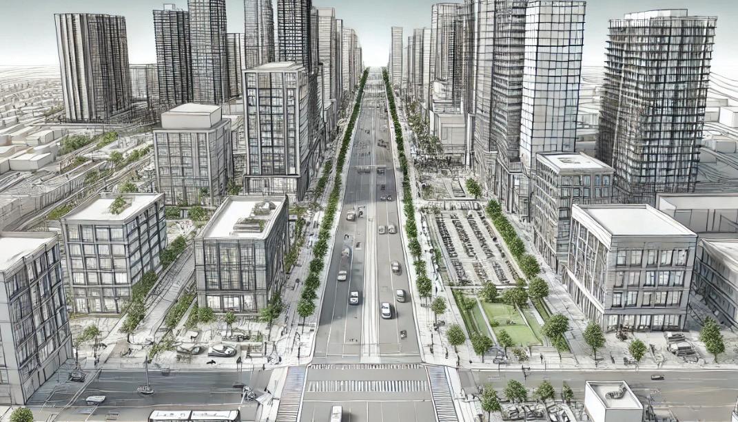
a) Footpaths: Footpaths should have a minimum width of 2.5 meters to accommodate high pedestrian traffic.
b) Amenity Zones: Multiple amenity zones of 2.5m x 5.5m modules must be planned along the length of either one or both footpath edges.
c) Amenity zones must accommodate trash bins, benches and cycle parking stands.
d) Amenity zones must also include dedicated vending zones for street-side vendors.
e) Lighting should illuminate the entire street edge. Additional pedestrian lights may be added, if the common streetlight leaves dark spots along the edge.
f) Public Art: Incorporate public art such as murals, interactive sculptures, etc.
g) Bus Shelters: Provide shelters at all bus stops to enhance rider comfort (Global Street Design Guide) without encroaching on the clear 2.5 m footpath space required.
h) Loading Zones: Dedicated space on side streets or within parking zones must be identified for loading zones.
High Streets sub-arterial roads serve as key retail corridors that attract significant foot traffic and support local businesses. These roads are characterized by their vibrant commercial activities and often feature a range of retail shops, cafes, and entertainment venues. The design prioritizes pedestrian safety and comfort, with wide sidewalks, street furniture, and enhanced public transport facilities to encourage shopping and social interactions.
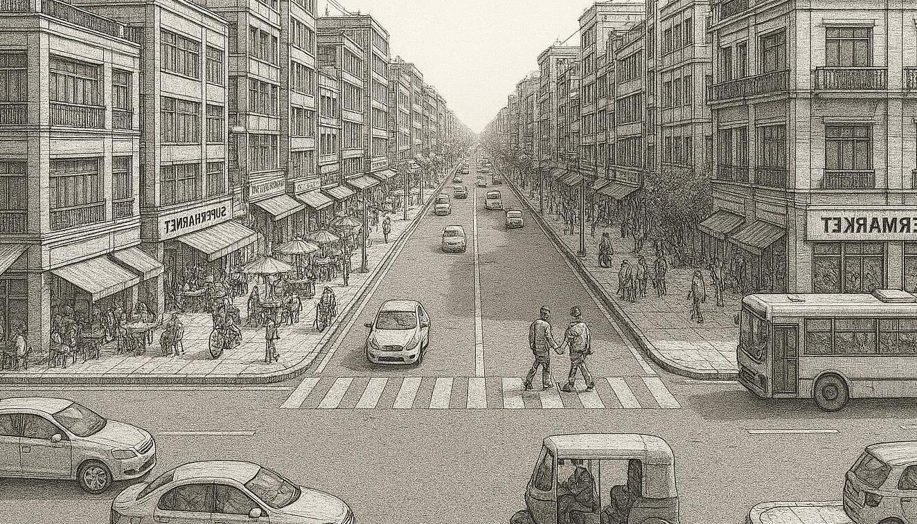

a) Footpaths: Footpaths in retail areas should have a minimum clear walking width of 2.5 meters to accommodate heavy foot traffic.
b) Amenity and Waiting Zones: Amenity and Car/Taxi Waiting zones of 2.5m x 5.5m modules must be planned alternatively along the length of either one or both footpath edges.
c) Amenity zones must accommodate trash bins, benches and cycle parking stands.
d) Space for short-term parking or waiting to be provided in between the amenity zones.
e) Lighting should illuminate the entire street edge. Additional pedestrian lights may be added, if the common streetlight leaves dark spots along the edge.
f) Bus Shelters: Provide shelters at all bus stops to enhance rider comfort (Global Street Design Guide) without encroaching on the clear 2.5 m footpath space required.
3. Institutional (Passive) Edges
Institutional edges are passive in nature fronting large school or college campuses, hospitals, or government facilities. These edges focus on providing access to institutions while ensuring safe and convenient routes for pedestrians and cyclists. The design may incorporate green spaces and landscaping to create a calming environment suitable for passive activities.
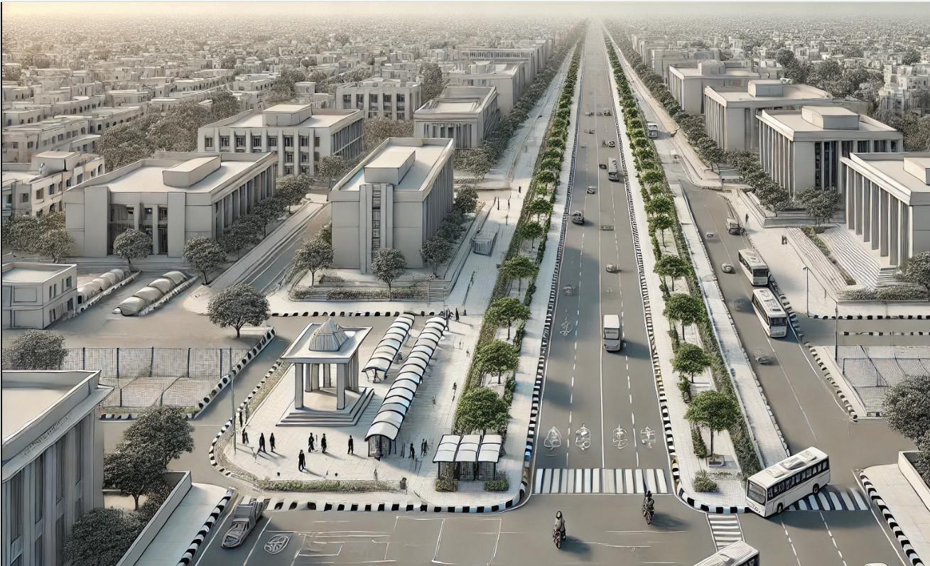
a) Amenity Zones: Must have continuous landscaped amenity zone at the edge of the footpath with provision of lighting and shade and frequent spaces for pause, such as benches, etc.s
b) Cycle Tracks: Dedicated cycle tracks should be provided along such edges.
Promenades and park edges front natural areas such as lakes or open spaces and are best used for recreational activities, walking, and cycling. These edges often include landscaped areas, public spaces, and amenities that promote leisure and outdoor experiences. The design aims to enhance the quality of life by providing attractive and accessible routes for residents and visitors, encouraging a sense of community and well-being
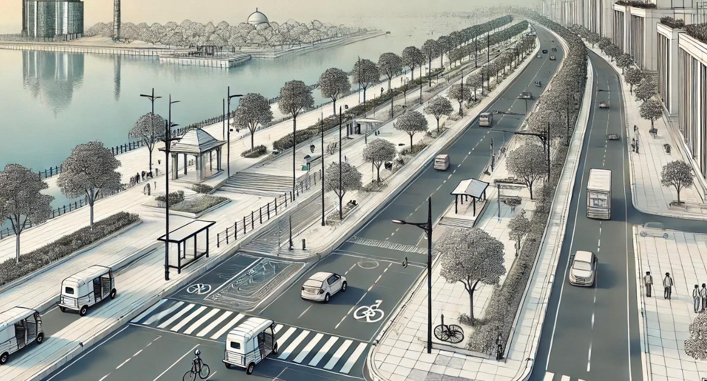
a) The Footpath and Cycle Tracks along such edges should be planned as an extension of the open space or as a garden or park by itself.
b) After leaving clear walking width of 2m and cycling width of 1.5m, the edge may be designed to include seating, playing and exercising facilities.
c) All such edges must be well-lit for safety.
Collector streets are designed to gather and distribute traffic from sub-arterial or arterial roads to local streets. They are typically narrower than arterial and sub-arterial roads and have lower speed limits. Collector streets must be spaced 500m to 1km apart within the street network.
Typical Width: 12 to 24m
Types of Collector Streets:
1. Mid-Rise Mixed-Use: Mid-Rise MixedUse collector streets are designed to support a blend of residential, commercial, and recreational activities within a compact urban environment. These streets facilitate a vibrant atmosphere by accommodating higher pedestrian and vehicular traffic volumes.
2. Low Density: Low Density collector streets primarily serve residential neighborhoods with lower traffic volumes. These streets provide direct access to homes and local amenities while ensuring safe circulation for residents.
3. High Rise Residential: High-rise residential collector streets are designed to accommodate the increased traffic demands associated with high-density living environments, such as apartment complexes and condominiums.
Figure 33. Section and Plan showing an ideal Collector street design; Source: Healthy Streets Design Workbook, ITDP.
18m wide with Symmetrical Footpaths
It is well-suited for areas with mixed land use, high pedestrian activity, and retail or commercial establishments while maintaining vehicular accessibility.
Cyclists will be in mixed traffic, hence streets should be traffic calmed to ensure speeds are within 30km/h, suitable for collector streets.
Tree pit level +150mm
Street vendor
Seating
Street Light
Existing tree pit grating level +150mm
1-side parking parking footpath two way shared street pedestrian-only median service lane
Speed hump BRTS cycle track
Tree pit with seating Property acess with ramp in MUZ
18m wide with Pedestrian malls
Pedestrian malls, that prioritise walking, cycling and public transport, can be designed in locations with heavy pedestrian footfall and vending locations.
Parking spaces for freight should be accomodated within limited off-peak hours.
Such streets can be considered for commercial markets and transit station areas.
Speed hump
Existing tree pit grating level +150mm
Street Vendor
Street Light
Tree pit with seating
BRTS cycle track 1-side parking parking footpath two way shared street pedestrian-only median service lane
1. Lane Configuration
a) Number of Lanes: Consider the carrying capacity needs as suggested in IRC:106-1990 Table 2 to determine lane configuration.
1:50
b) Lane Width: Collector street lanes widths should range from 3m to 3.5m.
2. Access Management
gradient defined differences.
a) Vehicular access to properties along collector streets must be strategically combined to reduce the interruptions to pedestrian and vehicle traffic moving along the street.
b) Vehicle access lanes or curb ramps should not exceed 4m in width.
Carriageway should have proper longitudinal gradient and camber (1:50) to allow for surface runoff.
3. Traffic Management
a) Speed Limits: Collector streets should be designed for a speed of 30-40 km/h, depending on the adjacent land uses and traffic conditions. This is consistent with the IRC 86: 2018
b) Traffic calming measures such as table tops and rumble strips should be used near schools, and high footfall areas.
c) Speed table should be provided on arterial and collector streets at Unsignalised junctions or Mid-block crossings with frequent pedestrian movement
4. Intersections and Crossings
a) Compact Intersections: Intersections should be compact with turning radius of less than 3.5m.
b) Roundabouts: The intersection of 2 collector streets of 2 to 3 lanes may be designed as a roundabout of radius 6-10m.
c) Signalized Intersection: The intersection of a collector street with an arterial or sub-arterial road or with any road of 4 lanes or more must be designed as a signalized intersection.
d) Zebra crossings of upto 3m width should be marked at all intersections and at a minimum spacing of 100 to 150m.
Figure 34. Illustration representing Lane design specifications; Complete Streets Design Workbook, ITDP
Table 03: Edge-to-edge width of a traffic lane according to street categories. Lane width is defined by the function of the
1. Footpath:
a) Need to be segregated, either by a level difference of 100 – 150m or by installation of kerb stones clearly defining the pedestrian space.
width
b) Must have a minimum width of 1.8 meters. For a shared cycle and pedestrian footpath, the minimum width should be atleast 3 meters.
c) Surface should be levelled and continuous through use of footpath ramps for wheelchairs and ramps at plot entry and exits. Ramp slopes should not exceed 1:12.
d) Stamped concrete or rectangular paver blocks are preferred. Special areas may also have stone pavers.
2. Amenities and Parking:
width of the pedestrian zone in a highintensity commercial area should be atleast 4m to accommodate high footfall.
a) Parking zones and Amenity zones of 2.5m x 5.5m modules must be planned alternatively along the length of either one or both footpath edges.
b) Parking or amenity zones should not be provided at street corner, rather they should be kept atleast 25m away from street corners.
Amenity zones must accommodate trash bins, benches and cycle parking stands.
Lighting should illuminate the entire street edge. Additional pedestrian lights may be added, if the common streetlight leaves dark spots along the edge.
streets Clear width of the pedestrian zone in a residential area should be a minimum of 1.8m for two wheelchairs to pass each other.
high intensity commercial
Clear width of the pedestrian zone in a highintensity commercial area should be atleast 4m to accommodate high footfall.
0.15m high (top of kerb should be at 0.15m) so that they aren't surmountable for vehicles. In narrow streets, MUZ can be optional or provided as discontinuous patches.
residential
Clear width of the pedestrian zone in a residential area should be a minimum of 1.8m for two wheelchairs to pass each other.
property entrances continuity 0.6m slope 1:12
Clear width of the pedestrian zone in a commercial area should be atleast 2.5m. commercial
Wide footpath: Footpath should continue across property entrances with 0.6m wide vehicle access ramp along the edge.
narrow streets
In narrow streets, MUZ can be optional or provided as discontinuous patches.
high footfall.
continuity 1-1.2m
property entrances
width of the pedestrian zone in a residential area should be
gratings Surmountable gratings, with holes that are perpendicular to the movement of wheels of a wheelchair, should be used over
Footpaths should be 0.15m high (top of kerb should be at 0.15m) so that they aren't surmountable for vehicles.
In narrow streets, MUZ can be optional or provided as discontinuous patches.
property entrances
Footpaths should have adequate gradient for surface runoff.
0.6m slope 1:12
Wide footpath: Footpath should continue across property entrances with 0.6m wide vehicle access ramp along the edge.
Footpaths
Narrow footpath: Where there is not enough width for an entrance ramp, footpath should slope gradually (< 1:12) to reach ground level at property entrances for wheelchair users.
Figure 35. Illustration representing Footpath design specifications for a collector road; Complete Streets Design Workbook, ITDP
Footpath should with 1 - 1.2m footpath width provide ramps tabletop
1. Storm water Drainage
a) Sustainable Drainage Systems (SuDS): Implement SuDS, such as permeable pavements, vegetated swales, and retention ponds, to manage surface runoff and enhance groundwater recharge. These systems also reduce the strain on conventional drainage infrastructure.
b) Adequate Sizing of Drains: Ensure that drains along collector streets are designed to accommodate higher flow volumes due to the convergence of smaller streets into the collector. This includes ensuring that pipes, manholes, and catch basins are appropriately sized (for example, ensuring manholes are spaced between 30-60 meters depending on pipe diameter).
c) Street-Level Drainage Integration: Design streets with proper grading to ensure runoff naturally flows into stormwater drains. Catch basins should be strategically placed at low points, intersections, and areas with high pedestrian traffic.
d) Water Retention and Treatment: For large collector streets, integrate stormwater retention and treatment areas to filter and slow the flow of runoff, improving water quality before it enters the main drainage system.
2. Water Supply and Sewage
a) Adequate Pipe Sizing: Ensure that water supply and sewage pipes are sufficiently sized to handle the increased demand from surrounding areas converging into the collector streets. Typically, 400-600 mm diameter pipes are used for collector streets, with spacing between manholes generally around 30-60 meters depending on local guidelines and sewer capacity.
b) Water Supply Connections: Provide a robust water supply system that can cater to residential and commercial needs along collector streets. Ensure that water supply pipes are strategically routed and easily accessible for maintenance. Consider future demands and make provisions for upgrades.
c) Sewage Network Integration: Connect the collector streets to the main sewage treatment plants, ensuring all buildings have proper connections for wastewater disposal. Use gravity flow design principles to minimize pumping stations, where possible.
d) Public Sanitation Facilities: Integrate public restrooms and sanitation facilities at regular intervals along collector streets, ensuring proper sewage connections and maintaining hygiene for residents and pedestrians.
Sewer/ Drainage Lines
Water Supply Lines
Electricity Cables
Telecommunication Cables
Gas Pipelines
Recommended depth: 2.0-6.0m for a Trunk Sewer Line
Recommended depth: 0.6-1.0 m for a service line 1.0-1.5m for a trunk line
Recommended depth: 0.6-1.0m for low tension cable 1.5-2.0m for high tension cable
The following section outlines the utility design requirements for the installation of underground services. To initiate a complete street design for a greenfield or retrofit development, underground layer should be implemented as a first layer complying with the minimum requirements outlined in the section below:
Recommended depth: 0.6-1.0m directly laid
Recommended depth: 2.0-3.0m
The placement of the utilities should comply with the below schematic representation, following the depth as per the above table:
a) Underground Utility Networks: Plan for the underground installation of utilities such as gas, electricity, and fiber optics along the collector streets to minimize visual clutter and maximize space for pedestrian and vehicular movement. This should be done with proper coordination to ensure easy access for future repairs and maintenance.
Sewer/ Drainage Lines
Water Supply Lines
Recommended depth: 2.0-6.0m for a Trunk Sewer Line
Recommended depth: 0.6-1.0 m for a service line 1.0-1.5m for a trunk line
b) Service Access Points: Ensure there are designated access points along the collector streets for utility companies to service and maintain gas pipelines, electricity lines, and fiber optic cables. These points should be located at regular intervals and be well-marked to allow for easy access during maintenance work.
Electricity Cables
Recommended depth: 0.6-1.0m for low tension cable 1.5-2.0m for high tension cable
Telecommunication Cables
Gas Pipelines
c) Smart Infrastructure Integration: For future-proofing, include provisions for smart city infrastructure, such as fiber optic cables for high-speed internet, smart street lighting, and electric vehicle charging stations. Plan utility spaces that accommodate these modern technologies while maintaining efficient service provision.
Recommended depth: 0.6-1.0m directly laid
Recommended depth: 2.0-3.0m
To ensure that project implementation is directed towards desired outcomes; and successes, failures and benefits are monitored and evaluated, a checklist is prepared to evaluate applications for street design essentially for new roads or for cases where the entire street is revamped. This checklist is not intended to alter or infringe the design standards, but is consolidated minimum standards that should be followed for developing and preserving safe operations of road facility. Following is a checklist categorized in three layers: A) Underground; B) Footpath; C) Cycle Tracks; D) Intersections; and E)
The placement of the utilities should comply with the below schematic representation, following the depth as per the above table:
d) Clearance and Safety: Maintain clearances between utility infrastructure, particularly gas and electricity lines, from other infrastructure like water supply and sewage pipes. This ensures safety and accessibility for maintenance and reduces the risk of utility conflicts.
LOCAL ROAD
Above-ground Utilities
ARTERIAL SUB-ARTERIAL COLLECTOR LOCAL ROAD
ELEC: Electricity Cable SWD: Sewerage/Drainage & Water Lines SEW: Sewerage
The following section outlines the utility design requirements for the installation of underground services. To initiate a complete street design for a greenfield or retrofit development, underground layer should be implemented as a first layer complying with the minimum requirements outlined in the section below:
Element Responsibility Features YES NO NA
Sewer/ Drainage Lines
Water Supply Lines
Electricity Cables
ARTERIAL SUB-ARTERIAL COLLECTOR
Telecommunication Cables
Recommended depth: 2.0-6.0m for a Trunk Sewer Line
Recommended depth: 0.6-1.0 m for a service line 1.0-1.5m for a trunk line
Recommended depth: 0.6-1.0m for low tension cable 1.5-2.0m for high tension cable
Recommended depth: 0.6-1.0m directly laid Gas Pipelines
Recommended depth: 2.0-3.0m
ELEC: Electricity Cable SWD: Sewerage/Drainage & Water Lines SEW: Sewerage
The placement of the utilities should comply with the below schematic representation, following the depth as per the above table:
36. Placement of the utilities, Source: Bhubaneswar Street Design Guidelines, BDA
1. Mid-Rise Mixed Use Street
Mid-Rise Mixed-Use collector streets are designed to support a blend of residential, commercial, and recreational activities within a compact urban environment. These streets facilitate a vibrant atmosphere by accommodating higher pedestrian and vehicular traffic volumes. They prioritize accessibility and connectivity, linking various land uses while promoting local businesses and community engagement.
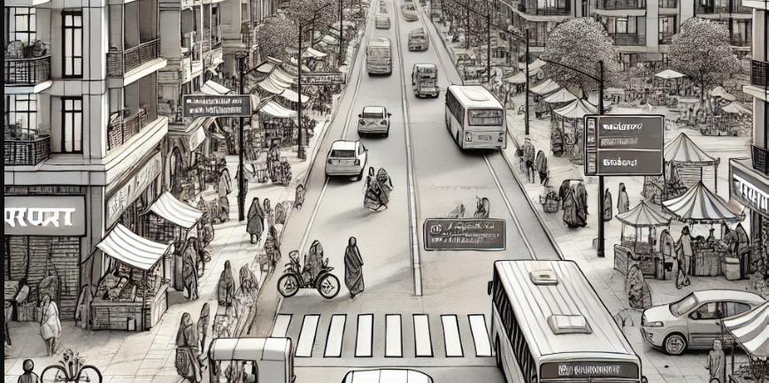
a) Carriageway: Collector streets designated for mid-rise mixed-use developments should maintain a minimum of carriageway width of 4.5m in either direction, or 6m for one-way streets to accommodate bypassing vehicles.
b) Footpaths: Footpaths should have a minimum width of 2.5 meters to accommodate the spillover from the commercial activity along plot edges. For a shared cycle and pedestrian footpath, the minimum width should be atleast 3.5 meters.
c) Tabletop Crossings: Crossings at high pedestrian volume locations should be designed as tabletop crossings with traffic calming treatment for vehicles entering the tabletop crossing.
d) Amenity and Parking Zones: Equal distribution of amenity and parking zones along the footpath edge should be provided, including atleast 5 modules of amenity zones at a stretch followed by 5 parking spaces.
e) Amenity Zones: Amenity zones in mid-rise, mixed-use streets must accommodate dedicated vending zones for street-side vendors.
f) Parking Zones: Only short-term parking must be provided along parking zones, to be specified with relevant signage.
g) Loading Zones: Dedicated space on side streets or within parking zones must be identified for loading zones.
h) Bus Facilities: Bus shelters must be provided within amenity zones, where available. Where amenity zones are not available, bus shelters must be designed to allow free flow of pedestrian movement through the stops.
Low Density collector streets primarily serve residential neighborhoods with lower traffic volumes. These streets provide direct access to homes and local amenities while ensuring safe circulation for residents. The design emphasizes a quieter environment, with features that promote walking, cycling, and community interaction, thereby enhancing the quality of life in less densely populated areas.
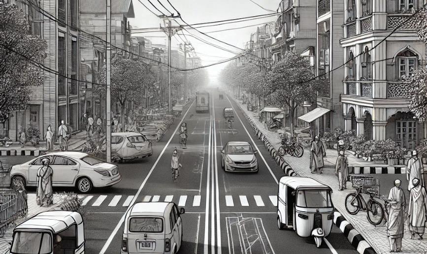
a) Amenity and Parking Zones: Atleast one module of amenity zone should be provided for 10 modules of parking spaces.
b) Amenity Zones: Must be landscaped with shading trees and shrubs.
High-rise residential collector streets are designed to accommodate the increased traffic demands associated with high-density living environments, such as apartment complexes and condominiums. These streets facilitate access to residential units and associated amenities while ensuring safe and efficient movement for pedestrians, cyclists, and vehicles. The design includes features that support public transportation and promote active transportation modes, reflecting the urban density of the area.
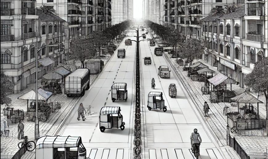
a) Access Management: Access curb ramps to high rise complexes should not be wider than 6m and must ensure continuous and smooth movement for pedestrians.
b) Footpaths: Footpaths should have a minimum width of 2.5 meters to accommodate the spillover from the commercial activity along plot edges, if any. For a shared cycle and pedestrian footpath, the minimum width should be atleast 3.5 meters.
c) Amenity and Parking Zones: Atleast 2 modules of amenity zone should be provided for 10 modules of parking spaces.
d) Amenity Zones: Must include trashbins, vending spaces and landscaping strips with shading trees and shrubs.
e) Bus Facilities: Bus shelters must be provided within amenity zones, where available. Where amenity zones are not available, bus shelters must be designed to allow free flow of pedestrian movement through the stops.
Slow/ Local streets are the most minor and most common street type in urban areas. They primarily serve residential neighborhoods and have low traffic volumes and speeds
Typical Width: Less than 12 m
Types of Local Streets:
1. Neighborhood Residential : Neighborhood Residential streets primarily serve residential areas, providing direct access to homes and local amenities. They are characterized by low traffic volumes, slower speeds, and pedestrian-friendly features that promote community interactions.
2. Mixed use shared street: MixedUse Shared Streets accommodate both vehicular and pedestrian traffic, supporting a blend of residential, commercial, and recreational activities. These streets are designed to prioritize pedestrian safety while allowing for shared use by cyclists and vehicles.
3. Informal pathways: Informal Pathways are unpaved or naturally surfaced routes that provide direct connections between residential areas and local amenities. They often vary in width and materials, prioritizing accessibility and informal use by pedestrians and cyclists.
Figure 40. Section and Plan showing an ideal Local street design; Source: Healthy Streets Design Workbook, ITDP.
6m wide Pedestrian-only streets
They suitable for areas with high pedestrian traffic, such as markets and transit station surroundings.
Prohibiting vehicles on these bustling streets helps reduce noise, conflicts, and enhances the pedestrian experience. Adequate alternate routes for motor vehicles should be planned.
Pedestrianization of streets can be implemented during specific hours of the day, taking into consideration the street’s current usage.
Existing tree pit grating level +150mm
Seating
Street Vendors Street Light
1-side parking parking footpath two way shared street pedestrian-only median service lane
BRTS cycle track
6m wide shared streets
Shared streets without segregated footpaths are ideal for local streets generally in residential/neighbourhood areas with lower traffic volumes, allowing pedestrians and cyclists to safely coexist with vehicles.
Segregated footpaths are not required when street is traffic calmed to 15km/hr.
Textured Surface for speed calming
Street Light
Property acess level ±0.00mm
Cyclist
Footpath
Speed hump
BRTS cycle track 1-side parking parking footpath two way shared street pedestrian-only median service lane
1. Lane Configuration
a) Slow/Local streets should consist of a minimum of one lane in each direction, with a lane width ranging from 2.5 to 3.0 meters. In cases where traffic volumes are very low, a shared lane may be appropriate.
2. Traffic Management
a) Speed Limits: The design of slow streets should incorporate traffic calming measures to maintain low speeds. This includes the use of speed humps, chicanes, or other vertical elements. The recommended speed limit is typically 20-30 km/h.
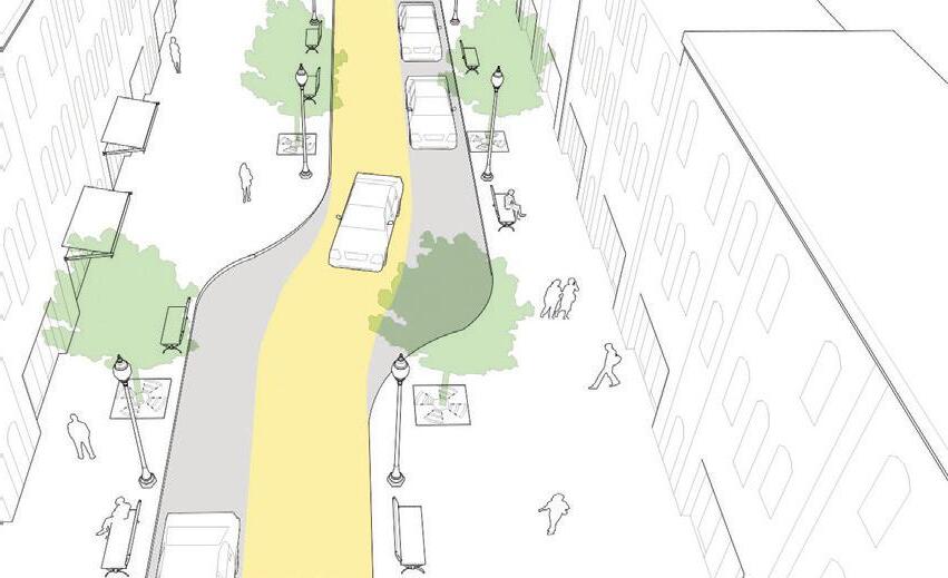
Figure 41. Illustration detailing out the lane configration and width; Complete streets design workbook ITDP
Figure 42. Illustration representing chicanes as a design strategy for traffic-calming; NACTO Global street Design Guidelines
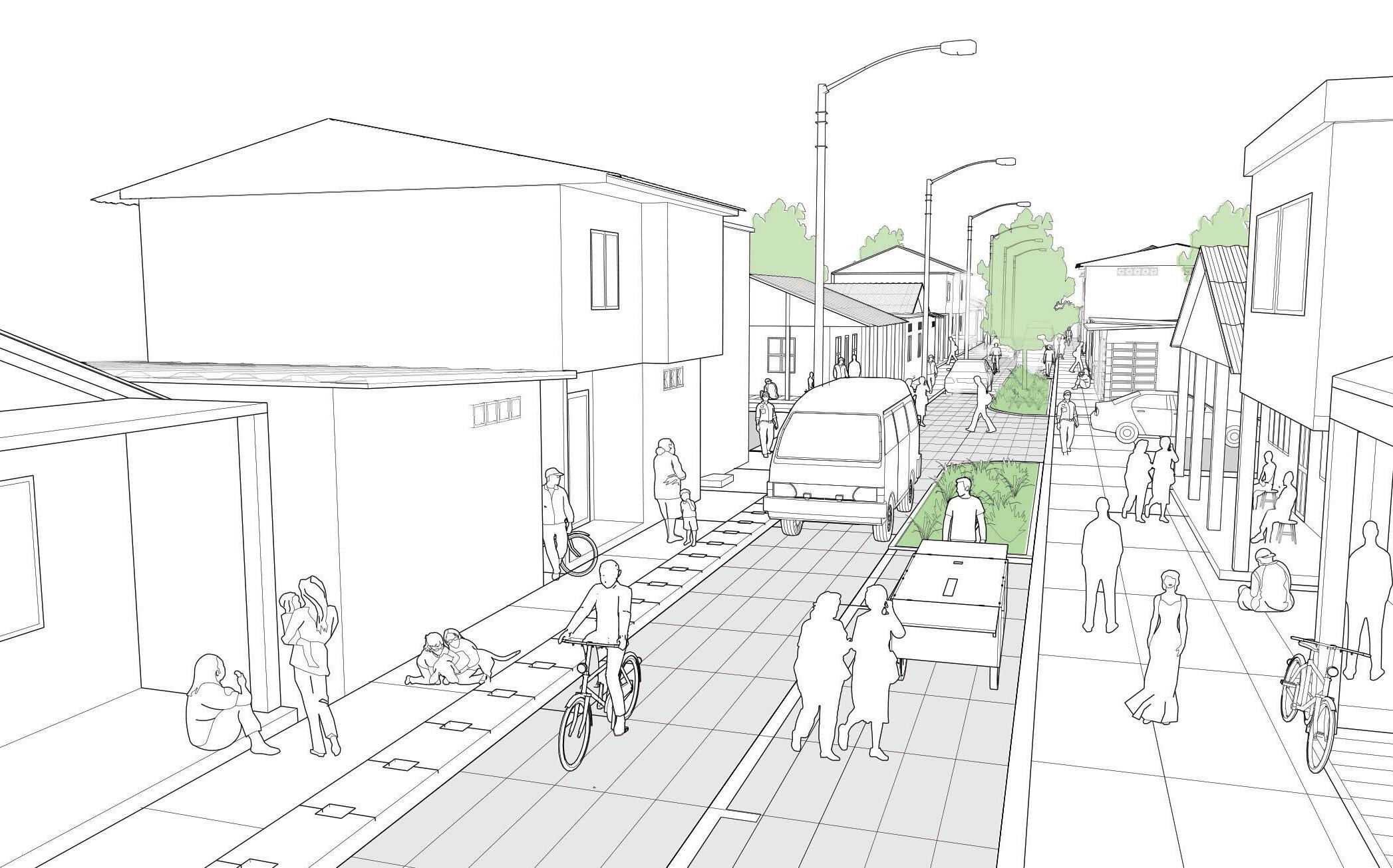
Figure 43. Illustration showing the overall street design of a local street; NACTO Global street Design Guidelines
Designing Streets for People
Designing for Pedestrians Sidewalks
1. Sidewalk Width: Sidewalks should have a minimum width of 1.8 meters wherever possible.
2. Surface Material: The surface of sidewalks should consist of durable, non-slip materials such as textured concrete or brick pavers to ensure safety in all weather conditions.
3. Lighting: Adequate lighting must be provided along sidewalks, with light poles spaced every 30 meters to eliminate dark spots. The height of light poles should not exceed 12 meters to avoid undesirable illumination of private properties.
4. Landscaping: Landscaping features, such as trees, shrubs, and planters, should be incorporated along the roadways to enhance aesthetics and provide shade for pedestrians. Trees should be spaced appropriately to avoid obstructing sightlines and pedestrian pathways.
Designing Streets for People
Designing Streets for People
Designing for Pedestrians Sidewalks
5. Crossings: Clearly marked pedestrian crossings should be installed at regular intervals to ensure safe access to homes, schools, and local amenities. Raised crossings may be considered to further enhance pedestrian safety.
Figure 44. Illustration showing edge design specifications and distance between light poles; Complete Street Design Guidelines, ITDP
Designing for Pedestrians Pedestrian Crossings x
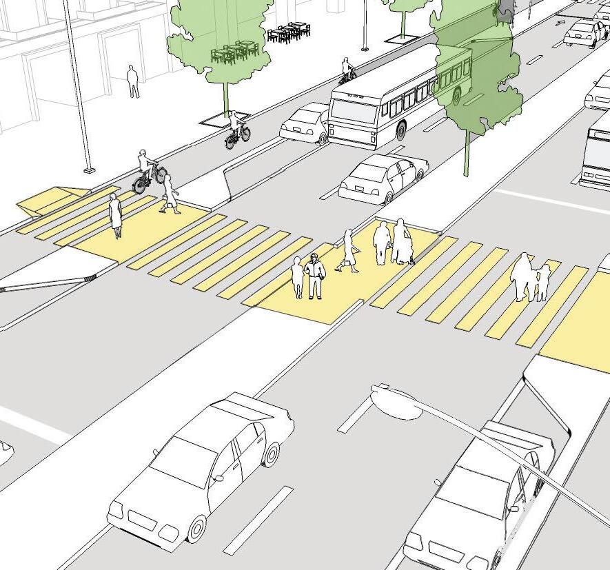
Pedestrian Volumes Signalized At Intersection
Mid-Block
Vehicular Speed
Vehicular Volumes
Pinchpoint/Yield
Crossing design in conjunction pinchpoints, provides distance at mid-blocks.
By reducing the roadway lanes to one lane at are forced to reduce to traffic coming from direction.
Pedestrian Volumes Signalized At Intersection
Mid-Block
Vehicular Speed
Vehicular Volumes
Staggered crossing should only be applied when the depth of the cutthrough allows full accessibility. They allow pedestrians to face the direction of oncoming vehicles, increasing visibility along the crosswalk.
Figure 45. Illustration of various traffic calming design strategies; NACTO Global Street Design Guidelines
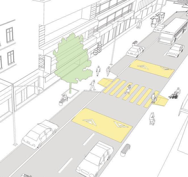
Pedestrian Volumes Signalized At Intersection
30 m space between light poles Traffic calmed crossings
Mid-Block
Vehicular Speed
Vehicular Volumes
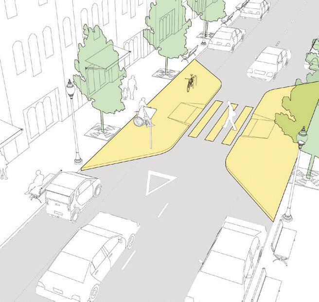
At mid-block crossings where motorist compliance is low, use vertical deflection measures such as speed bumps, tables, and cushions to reduce motorist speed and warn them of the presence of an upcoming pedestrian crossing.
Narrow Sidewalk
Maintain a lane width pinchpoint for emergency
The minimum width of the median should be 3 m and the offset between the two legs of the pedestrian crossing should not exceed 1 m , keeping crossing distances to a minimum.
> 1.8 m
Quiet streets in low-density contexts might have Ribbon Sidewalk
Pedestrian Volumes Signalized At Intersection
Mid-Block
In low-density streets where the sidewalk sits between a Narrow Sidewalk with Trees
Vehicular Speed
Vehicular Volumes
Vertical speed control elements should be set back 5–10 m from the crossing according to vehicular speed. A series of bumps before the crossing increases compliance levels.
Medium-density
In situations where dedicated cycle tracks cannot be provided, shared street designs can accommodate both pedestrians and cyclists within the same space.
1. Shared Space Design: Shared streets should have a minimal vertical separation between different modes of transport. The design should prioritize pedestrian movement while allowing cyclists to use the same area.
2. Width and Surface: The shared roadway should have a minimum width of 6 meters to accommodate both pedestrians and cyclists comfortably. The surface should be made of highquality, durable materials that provide a non-slip surface for safety.
3. Traffic Calming Measures: Implement traffic calming measures such as raised intersections, speed humps, or textured pavement to encourage lower vehicle speeds and enhance safety for all users.
4. Parking Guidelines - On-street
a) On-street parking should be provided only where street width and traffic flow allow. On narrow streets, it can be limited to one side to avoid congestion.
b) Parking spaces should be planned based on the width of the carriageway and the space required for vehicles. The typical space required for parallel parking is around 2.5 meters in width and 6 meters in length per vehicle.
c) Setbacks from intersections: Parking should not be allowed within 15-20 meters of an intersection to avoid obstructing visibility and traffic flow.
Figure 46. Illustration detailing out the elements of a shared street; Complete Streets Design Workbook, ITDP
Neighborhood Residential streets primarily serve residential areas, providing direct access to homes and local amenities. They are characterized by low traffic volumes, slower speeds, and pedestrian-friendly features that promote community interactions.
a) Traffic Management: Neighborhood Residential streets should prioritize pedestrian and cyclist safety by maintaining low traffic volumes. Speed humps or other traffic calming measures should be installed at regular intervals to discourage speeding
Mixed-Use Shared Streets accommodate both vehicular and pedestrian traffic, supporting a blend of residential, commercial, and recreational activities. These streets are designed to prioritize pedestrian safety while allowing for shared use by cyclists and vehicles.
a) Traffic Management: Mixed-Use Shared Streets should accommodate both vehicular and pedestrian traffic. Traffic calming measures should be applied to maintain low vehicle speeds.
b) Pedestrian and Bicycle Access: Sidewalks should be a minimum width of 2.0 meters, and shared spaces should allow pedestrians and cyclists to navigate freely. Cycle tracks may be integrated into the shared space and demarcated with painted lines or signage.
c) Public Spaces: Design features such as seating areas, public art, and landscaping should encourage social interaction and community engagement.
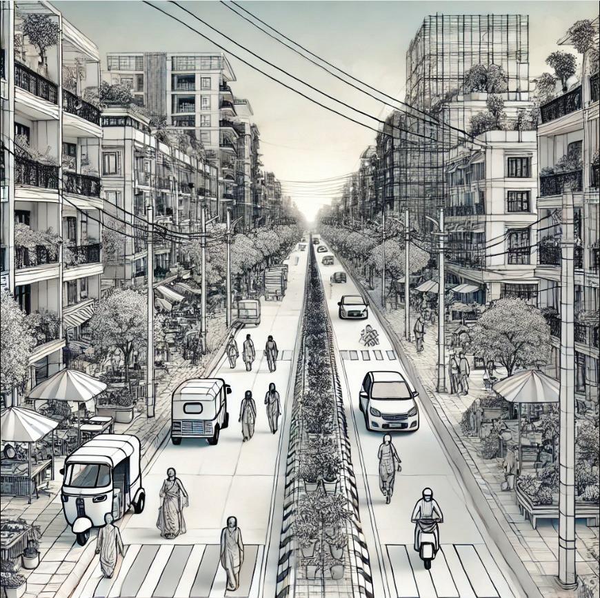
Informal Pathways are unpaved or naturally surfaced routes that provide direct connections between residential areas and local amenities. They often vary in width and materials, prioritizing accessibility and informal use by pedestrians and cyclists.
a) Design Flexibility: Informal pathways may vary in width and surface material, often being unpaved or constructed from natural materials. They should prioritize direct connections between residential areas and local amenities.
b) Accessibility: Ensure that informal pathways provide accessibility for all users, including individuals with mobility challenges. Pathways should be free of obstructions and have gentle slopes where applicable.
c) Landscaping: Encourage natural landscaping along informal pathways to enhance the environment and provide shade, while maintaining visibility and safety for users.
Bus stops provide safe and comfortable waiting spaces. They should be located such that they are easy to identify and do not obstruct the walking zone. Bus stops should be placed such that buses can pullover in their original path and do not need to get into a niche (bus bay), thus ensuring smooth movement of traffic. A typical bus stop shelter should be 9mx2.5m in size. The length of the bus stop should be determined based on the number of buses and expected volume of buses using the stop. For seamless multi-modal integration, relocate the existing bus stops wherever necessary to the nearest public transport interchange options. Ensure the placement of new bus shelters in closer proximity to other modes of public transport.
Location
In designing urban streets and spaces, it is essential to create environments that cater to the diverse needs of all users, ensuring inclusivity and accessibility. The guidelines presented here are focused on fostering seamless public transport integration, promoting barrier-free movement, and making spaces child-friendly. By prioritizing these elements, we can create streets that not only support efficient transportation but also enhance safety, convenience, and comfort for pedestrians of all ages and abilities. These principles serve to ensure that cities are not only functional but also equitable, welcoming, and sustainable for all residents, including those with mobility challenges, young children, and public transport users.
1. Bus Shelters: Bus shelters should be installed at all major bus stops along the streets to provide protection from weather elements. Each shelter should accommodate at least 4-6 passengers comfortably and include seating. Shelters should be accessible, with a minimum height clearance of 3 meters and equipped with information panels displaying routes and schedules (ITDP India Street Design Manual).
2. Bus Signs: Clear and visible bus signs must be placed at each bus stop, providing essential information about routes, schedules, and operational details. Signs should be positioned at a height of approximately 1.5 to 2.0 meters for easy visibility from both the street and sidewalk (Urban Street Design Guide).
3. Accessibility Features: Ensure bus stops are accessible for individuals with disabilities by incorporating features such as low curbs and tactile indicators to assist visually impaired users in navigating to and from the bus stops (Bhubaneswar Street Design Guidelines).
4. Waiting Areas: Designate waiting areas at bus stops that are free of obstructions, allowing for safe boarding and alighting from buses. These areas should be clearly marked, well-maintained, and situated close to pedestrian pathways (Global Street Design Guidelines).
Footpaths >4.5m wide
For footpaths > 4.5m wide, bus stops should be in the MUZ.
5. Lighting: Adequate lighting must be provided at bus stops and shelters to enhance safety and visibility during nighttime use. Light fixtures should be positioned to minimize glare for passengers and drivers (ITDP India Street Design Manual).
<4.5m wide
For footpaths < 4.5m wide, bus stops should be pushed to the wall to ensure sufficient space in the front for walking zone.
Figure 48. Bus shelter design specifications; Healthy Streets Design Workbook, ITDP
Designing Streets for People Designing for Pedestrians Universal Accessibility
6.3.8 | Universal Accessibility
1. Ramps: All curbs at crossings and public transport stops must include ramps to facilitate access for individuals with mobility challenges. Ramps should have a maximum slope of 1:12 and a width of at least 1.8 meters, as recommended in the Global Street Design Guidelines.
Pedestrian ramps are inclined planes facilitating the access of sidewalks for people using wheelchairs and other personal mobility devices, as well as those pushing strollers, carts, or heavy luggage. They are generally composed of three elements: the slope, the top landing, and the side flares.
• Slope The slope should be constructed of non-slip materials and be of a maximum slope of 1:10 (10%)—ideally 1:12 (8%). The ramp width should be as wide as the clear path: minimum 1.8 m wide, 2.4 m recommended.
• Top Landing
2. Tactile Paving: Install tactile paving at key crossing points and public transport stops to assist visually impaired individuals in navigating their environment. The tactile surfaces should contrast visually with the surrounding pavement to ensure clear identification (Urban Street Design Guide).
3. Signage:
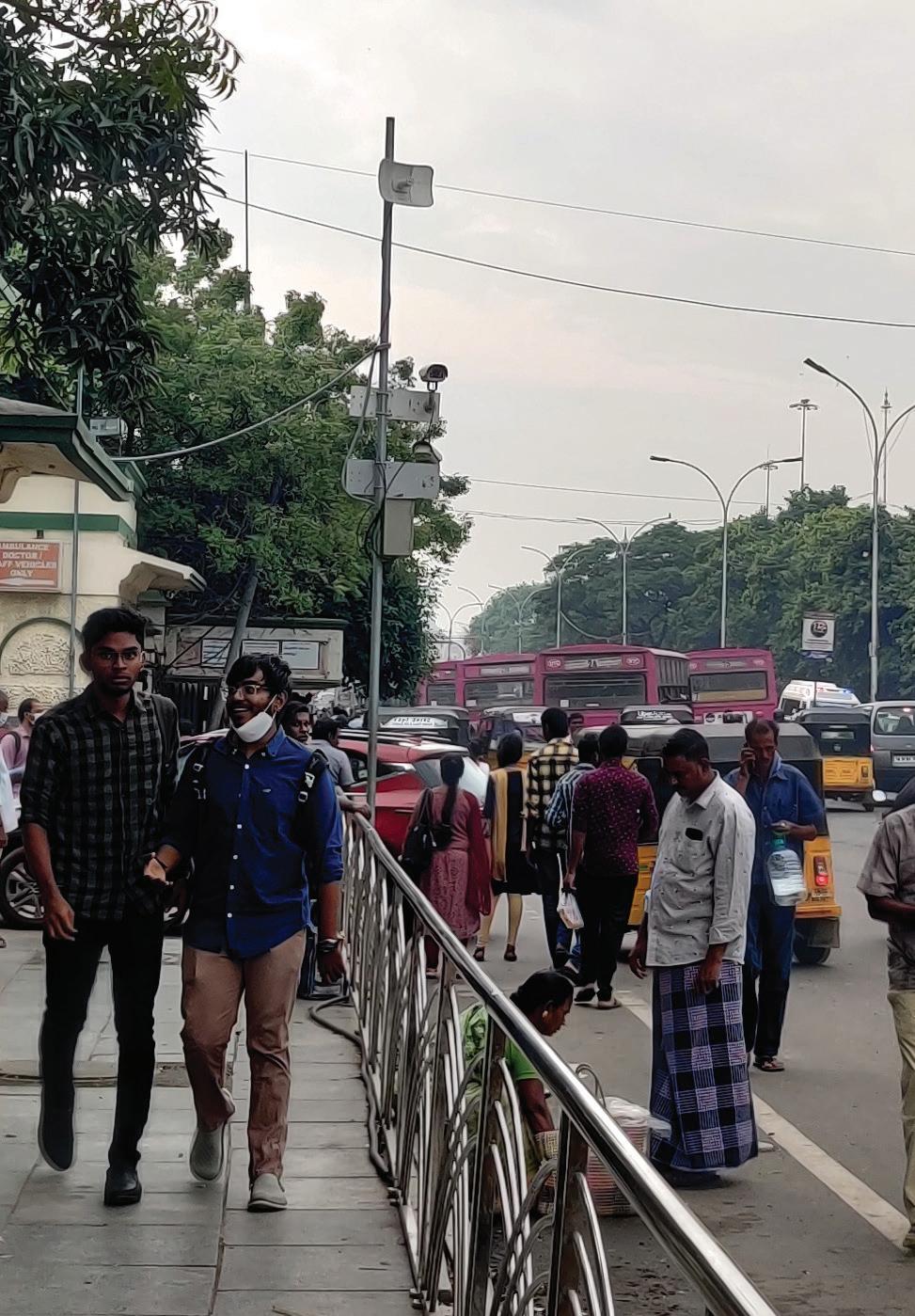
The top landing is located at the top of the ramp and allows ramp access across side flares. The landing should be as wide as the clear path or minimum 1.8 m wide.
• Side Flares
Footpaths should continue across local streets as table-tops with ramps for vehicle access.
in MUZ
Side flares are intended to prevent tripping hazards. Side flare slopes cannot exceed 1:10. Grade breaks at the top and the bottom must be perpendicular to the direction of the ramp.
Pedestrian ramps can be oriented parallel to sidewalks, where space is limited and it is difficult to fit a top landing. A level landing of a minimum 1.8 m length accommodates the maneuvering of a wheelchair.
a) Provide clear, legible signage throughout the streets to guide all users, including those with disabilities. Signs should use high-contrast colors and large fonts, with pictograms included for better comprehension (Bhubaneswar Street Design Guidelines).
Detectable Surfaces
Provide tactile paving or detectable warning strips at curb ramps and other transitions between pedestrian, vehicular, or shared areas.
Detectable surfaces should provide a distinctive texture intended to have a uniform meaning in alerting people to the approach of conflict zones.
Signage should be located at 0.25m from the kerb edge with minimum 2.1 m vertical clearance from the finished footpath level to the bottom of the signage board.
Location
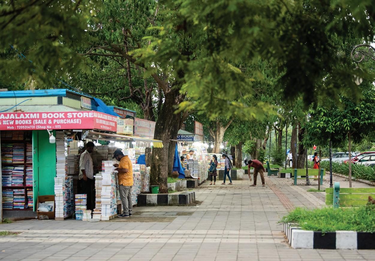
Signage should be located at 0.25m from the kerb edge with minimum 2.1 m vertical clearance from the finished footpath level to the bottom of the signage board.
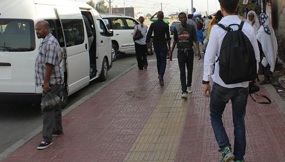
Multiple informatory signs can be combined on a single pole to reduce clutter.
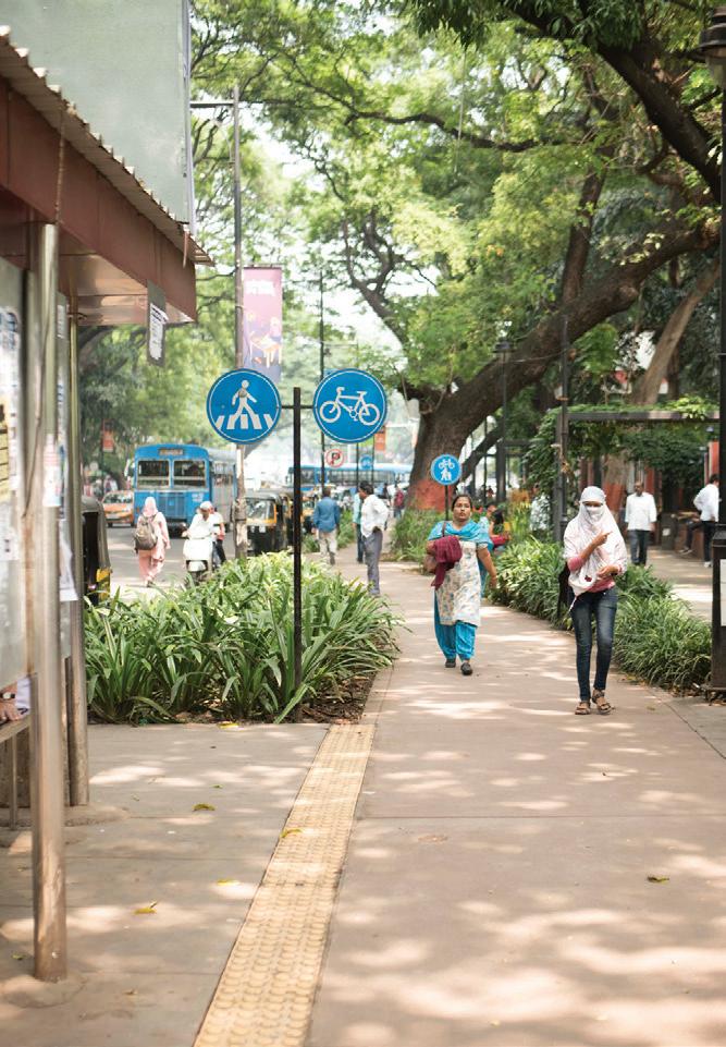
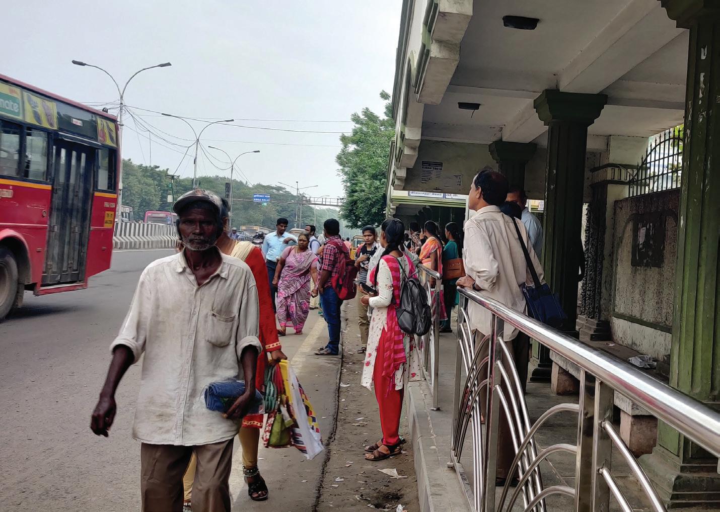
Braille Signage
Braille sign boards* should be located between 1.4-1.6m from finished footpath level. *For signage design details, please refer to IRC:SP:117
All signages shall adhere to the specifications mentioned in IRC: 67 - 2021 Signage should be placed perpendicular to the line of traffic, on the left side of the road with clear visibility.
Figure 49. Tactile Paving; Healthy Streets Design Workbook, ITDP Figure 50. Signage Design, ITDP
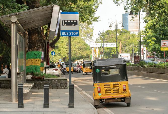
Orientation
assist visually impaired pedestrians. Crossings should be raised or textured to enhance visibility and safety for all users (Global Street Design Guidelines).
1. Protection and Safety
a) Speed Limits: Implement lower speed limits (preferably 20-30 km/h) in areas with high pedestrian activity, particularly near schools, parks, and residential neighborhoods. This helps reduce the risk of accidents involving children.
b) Traffic Calming Measures: Incorporate traffic calming measures such as speed humps, raised crossings, and curb extensions to slow down vehicular traffic. These features should be strategically placed to enhance safety near schools, playgrounds, and community centers.
2. Safe Crossings
a) Crosswalk Design: Pedestrian crossings should be marked at all major intersections and near schools. Use high-visibility paint and additional signage to alert drivers to the presence of pedestrians.
b) Raised Crossings: Implement raised pedestrian crossings at key locations to provide a clear and safe path for children. These crossings should be designed to slow down vehicle speeds and ensure visibility.
c) Audible Signals: At traffic signals, provide audible signals for visually impaired pedestrians, ensuring that all children, regardless of their abilities, can cross safely.
3. Accessible Routes to Schools and Play Areas
a) Direct Pathways: Design safe and direct routes to schools, parks, and recreational areas.
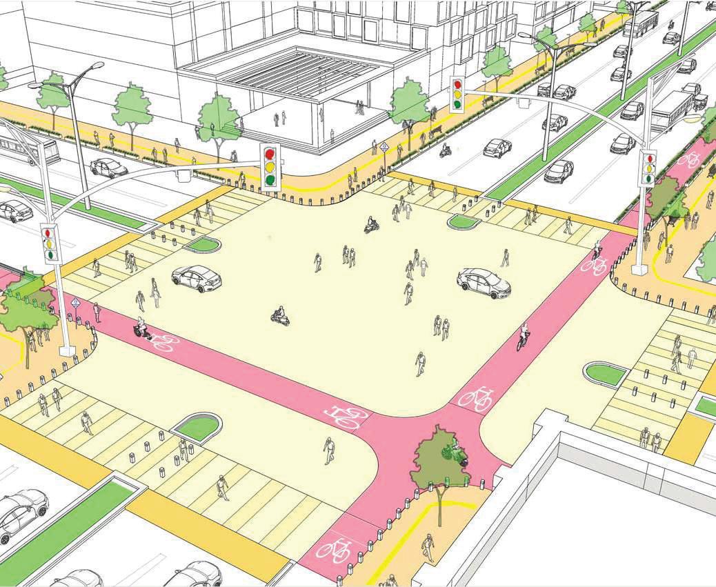
Figure 51. Illustration depicting Safe crossings for child friendly street design; Bhubaneswar Child Friendly Public Space Design Guidelines, BDA
Ensure these routes are well-maintained and free of obstacles, providing a clear path for children to walk or cycle.
b) Signage: Use clear, child-friendly signage to guide children to school and play areas. Signs should feature bright colors, simple language, and illustrations to enhance understanding.
4. Community Engagement
a) Involve Children and Parents: Engage children and their parents in the design process to understand their needs and preferences. Conduct workshops and surveys to gather input on amenities and features that enhance safety and enjoyment.
b) Awareness Programs: Implement community awareness programs to educate children and parents about road safety, encouraging safe behaviors when navigating streets.
5. Playful Design Features
CHILD FRIENDLY STREETS
a) Interactive Elements: To create a welcoming environment for children, incorporate playful and engaging design elements, such as colorful pavement markings, murals, and interactive street furniture.
ACCESSIBILITY GUIDELINES
b) Community Spaces: Designate areas along streets for informal play and social interaction. These spaces should be safe and easily accessible, encouraging children to engage with their surroundings.
6. Visibility and Awareness
a) Driver Awareness: Use signage such as “Children at Play” and “School Zone” indicators
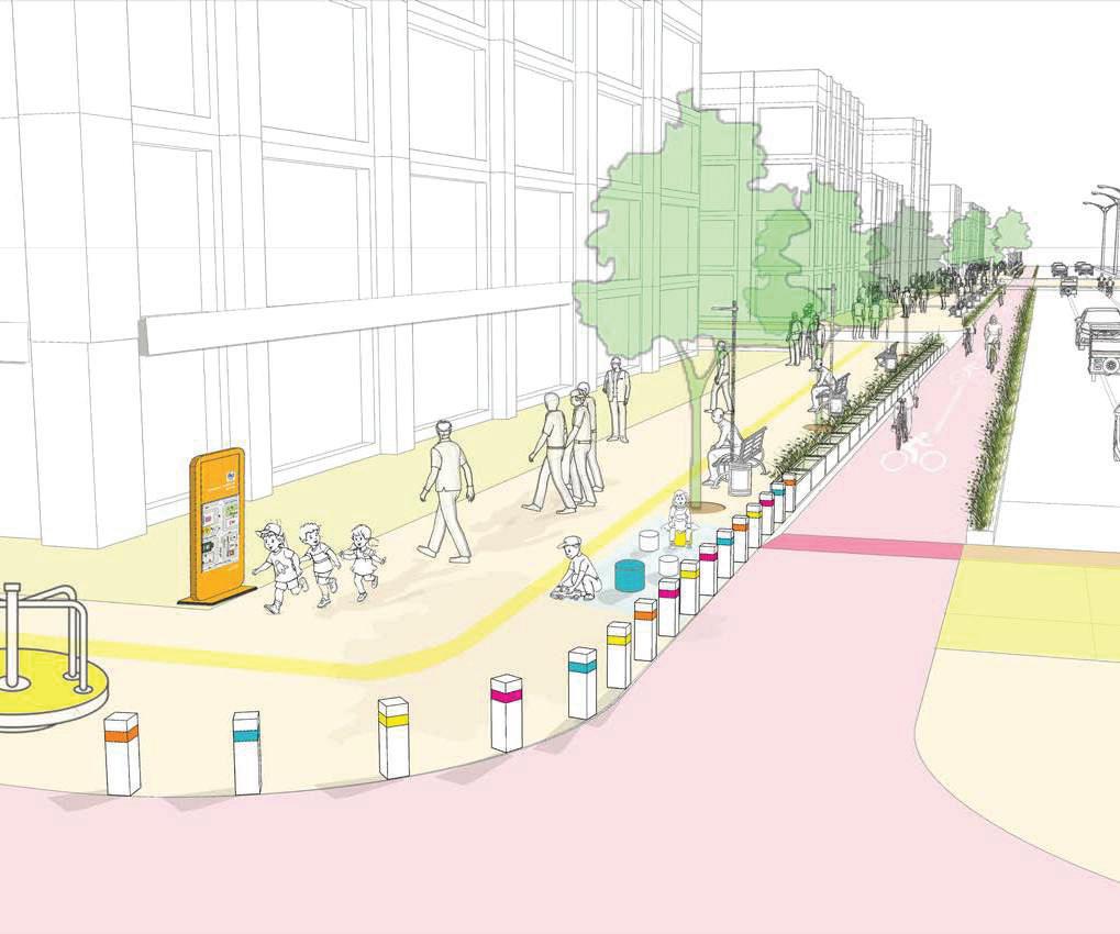
depicting playful design elements and sidewalk design for child friendly streets; Bhubaneswar Child Friendly Public Space Design Guidelines, BDA
drivers remain vigilant.
b) Landscaping Considerations: Ensure that landscaping does not obstruct sightlines at crossings and intersections, allowing children and drivers to see each other.
A B

Public consultation and surveys


C
Data collection & Analysis

Enhancing pedestrian safety Demography
Public transport accessibility
Traffic and Movement Analysis
Existing Infrastructure assessment

Creating sustainable transportation
Creating childfriendly spaces
Traffic Volume
GIS and Mapping Context understanding

Infrastructure
The development of Complete Streets guidelines in Rajkot is a crucial initiative aimed at enhancing the city’s urban mobility and inclusivity. A “Complete Street” is designed to be accessible, safe, and efficient for all users, including pedestrians, cyclists, motorists, and public transport users.
D
E
F
Design Implementation Management & Monitoring

Policy & Guidelines
Community Engagement


DPR & BOQ (Annexure - 1)

Funding and resources
Review and Feedback Communication strategy


Street Assessment Management Plan (SAMP) (Annexure - 3)
Funding and resources for improvement Concept development (Annexure - 2) Prioritization of projects

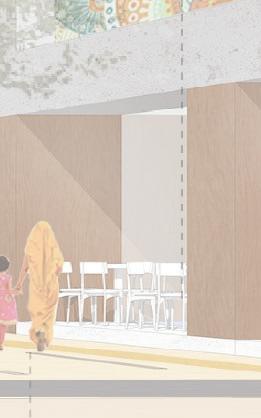
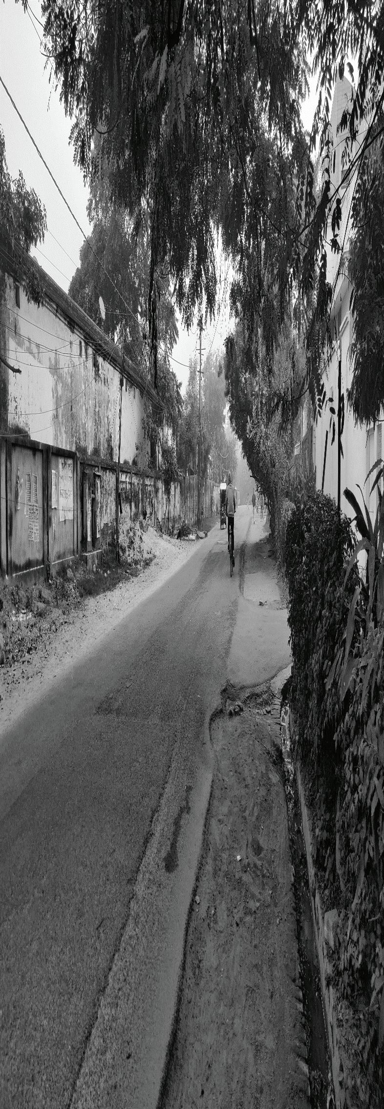
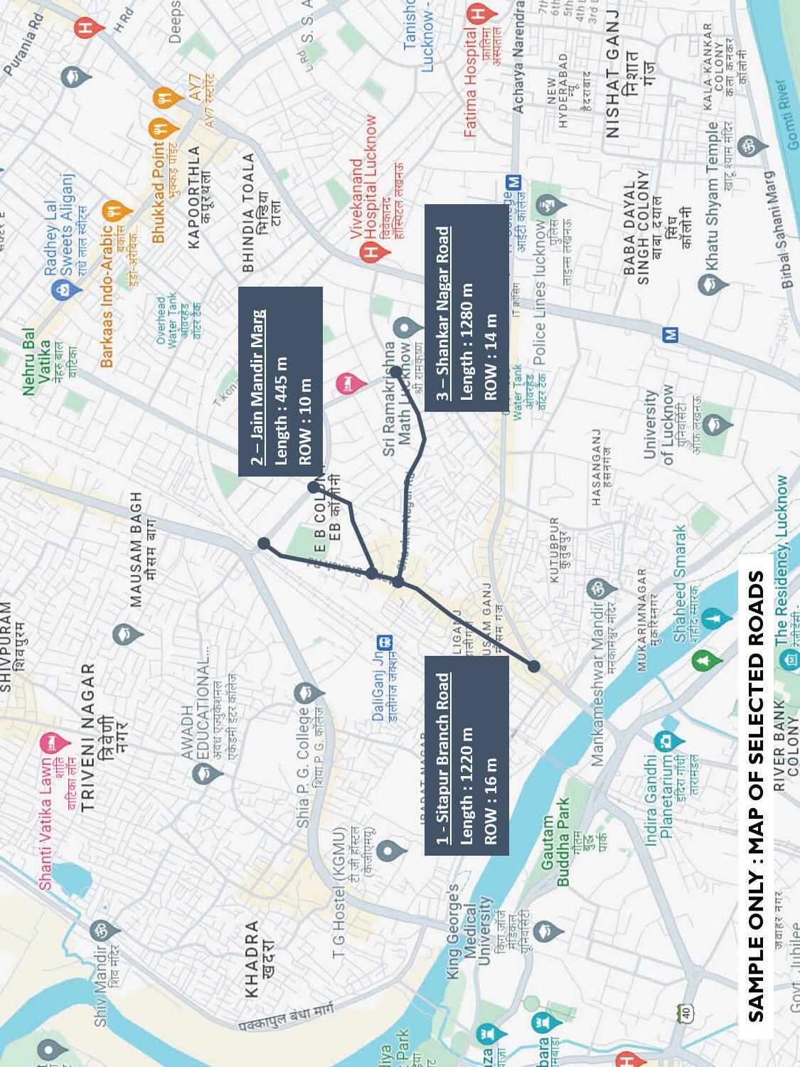
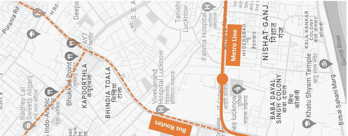

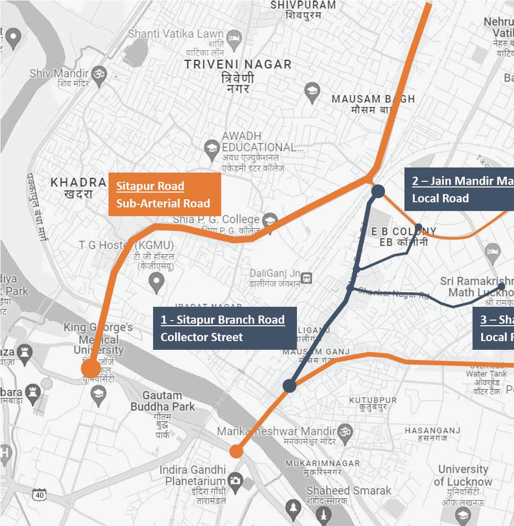
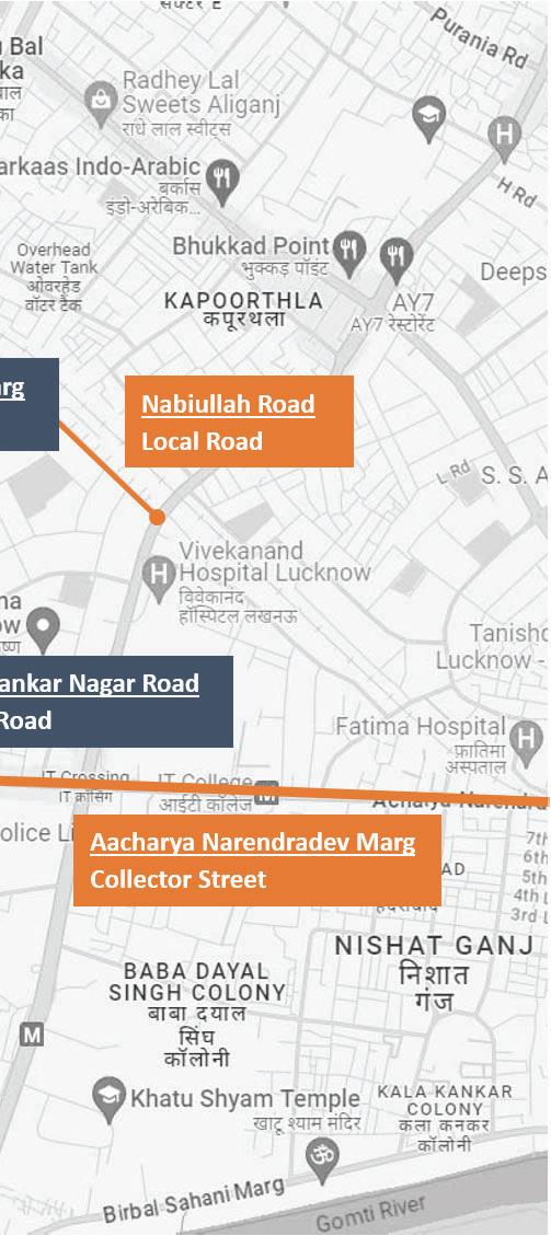
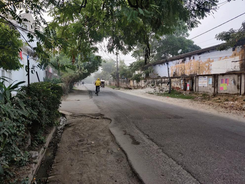
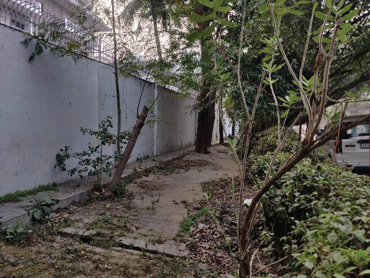
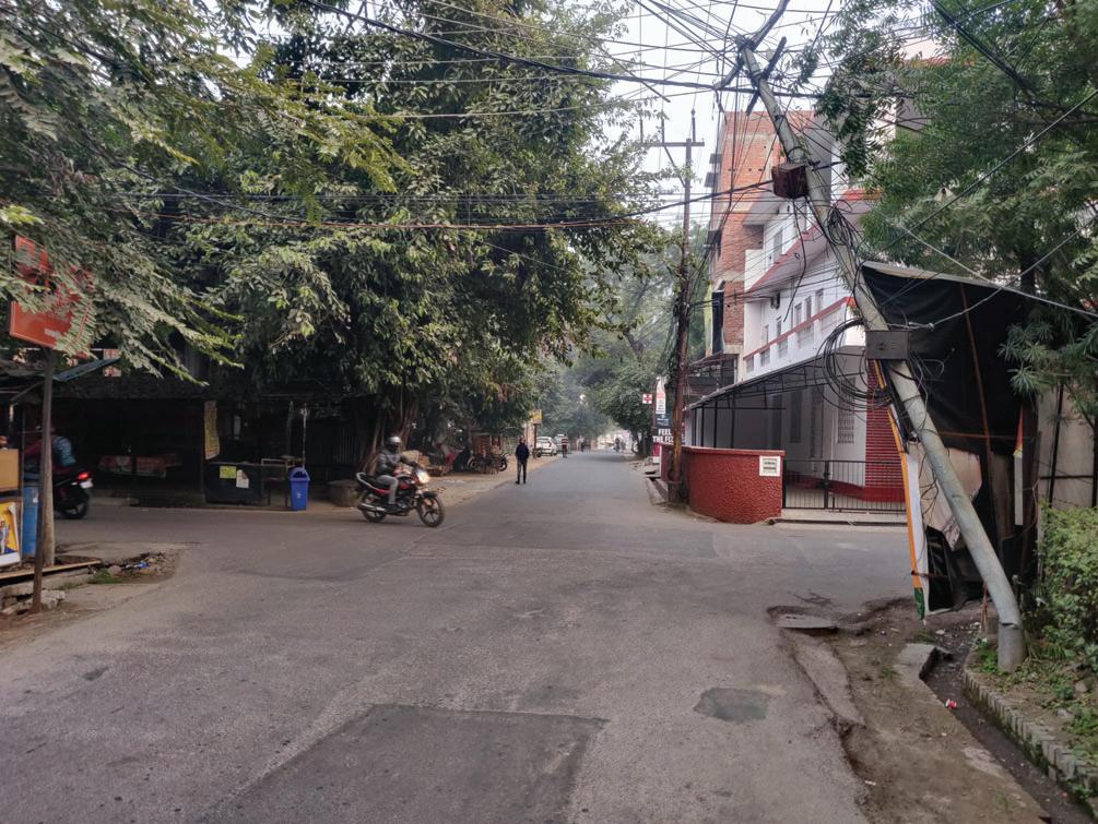
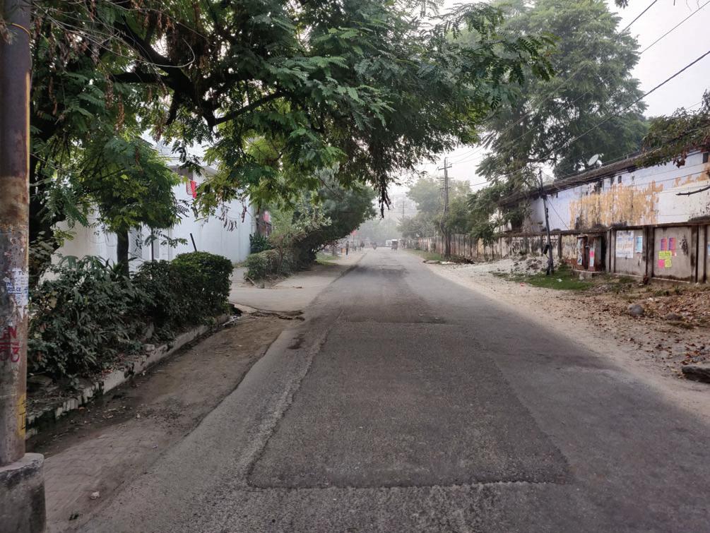

Neatly laid power lines, beneath the footpath
Power lines encased in HDPE pipes
Inspection chambers at regular intervals
Depth separation of LT and HT cables

Pipe and manhole system

Adjacent to carriageway wherever possible
Inlet points, at manholes with gratings
Drain channel to carry water along road edge

Minimum 2m* wide clear walking space


Universally accessibility with max. height 150mm
Ramps at property entry & table-tops / dropkerbs at crossings
Crossings at 150m- 200m interval
*Refer IRC 103: 2022 for widths across various landuses.

Uniform carriageway from Junction-Junction

Equal no. of lanes throught the way
Travel lane widths of 3m and to never exceed 3.5m
Reasonable slope for drainage of water 3m each 1 : 50





Tree pits-grating of radius 1m – 1.5m
Tree pits filled with landscape if no grating



Landscape strips below paved surface for water flow





Landscape strips of min. 600 mm to separate travel lane and footpath.




Dedicated parallel parking bays - 2W,3W,4W
Differently abled parking at 3.6 x 6.5 m with a ramp slope of 1:15
Provided within the multi utility zone / footpath

Universally accessible, vandalism proof & durable

Integrated and planned with the street design.


Waste bins at 50 -75 m distance

Installed at a distance of 3 times the pole height
HDPE pipes under MUZ / footpath for cables.


Neutral bright white LED lights
Brightness between 25 - 30 LUX
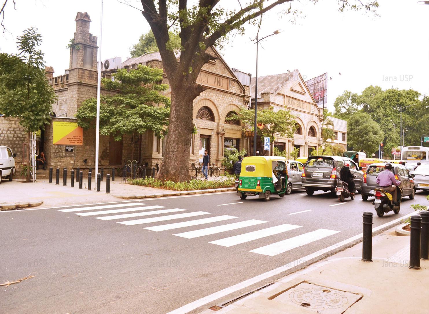



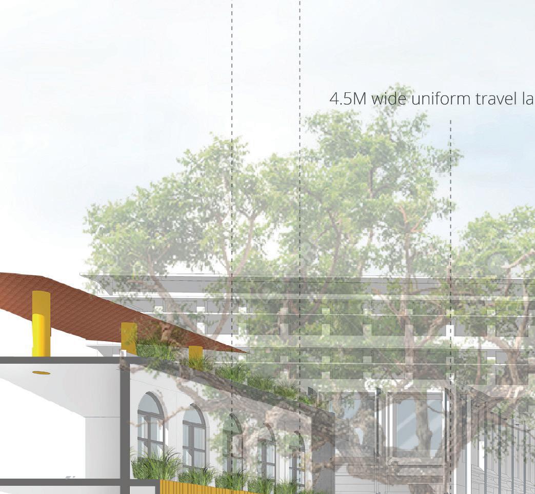

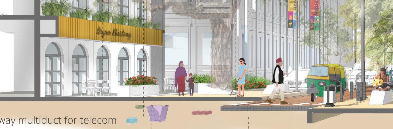
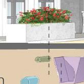



• condition

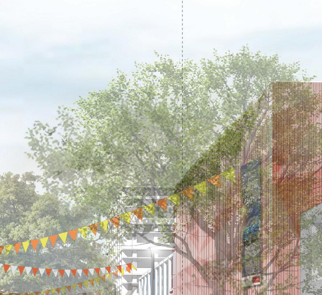
Preserve the road in its originally constructed

• Protect adjacent resources and user safety
• route • damaged roads
Provide efficient, convenient travel along the

Prevent the accidents caused due to faulty and
• Increase the life of the road.
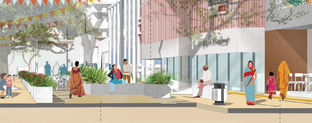


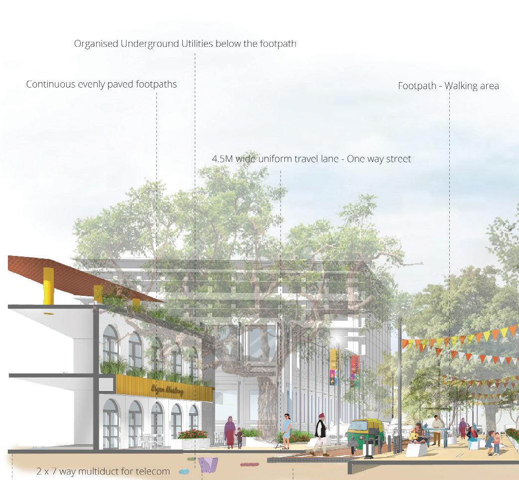
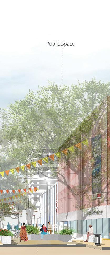
• Preserve the road in its originally constructed condition
• Protect dependent infrastructure and users.
• Provide efficient and convenient travel along the route
• Prevent accidents caused due to faulty and damaged roads
• Increase the life of the road
Additionally
• Keep the safety of road users and to decrease the inappropriate movement of traffic
• Maintenance of various components of roads such as pavement, drains, shoulders, side edges etc. provides better service to the user of the road
• It reduces the petrol consumption of vehicles and it prevents the wear and tear of vehicles tyres
Comprise works to restore roads and road-related facilities to their normal operating conditions after they are damaged by road accidents or natural causes.
It is impossible to foresee the frequency, but such maintenance requires immediate action.
Substantial repair works carried out at an appropriate time interval (every 3year, 5-year, 8-year, 10-year etc.), based on the age, investment, and initial design of roads is known as periodic maintenance.
Involves the following Reconstruction, improvement, or rehabilitation works on any road sections
Periodic repairs are carried out by contractors which are invited at specific intervals.
Day-to-day repairs which are done properly to the road pavements are known as routine repairs.
Goal
Prevent or delay pavement distresses. Routine maintenance includes regular street sweeping and crack sealing.
Elements to check
Pavement potholes, cracks, ruts/settlements, deformations, local aggregate loss, edge break, scratches etc.
Drainage
Other structures and facilities Markings, guardrails/handrails, signboards etc
The travel lane comes under the part of day -to -day repairs
Due to heavy traffic, variation in climatic condition, variety of traffic and improper quality, the potholes are developed on the surface of the road and has to be treated on regular basis .
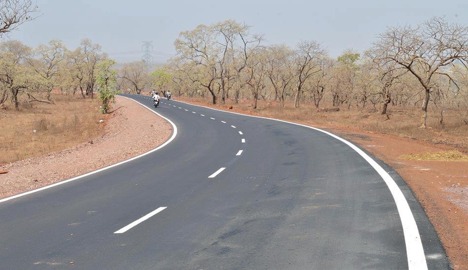
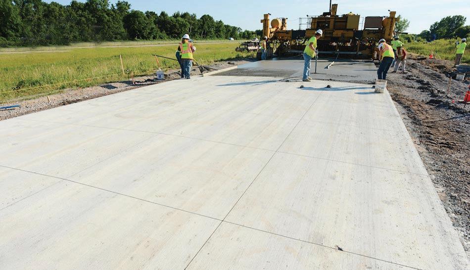
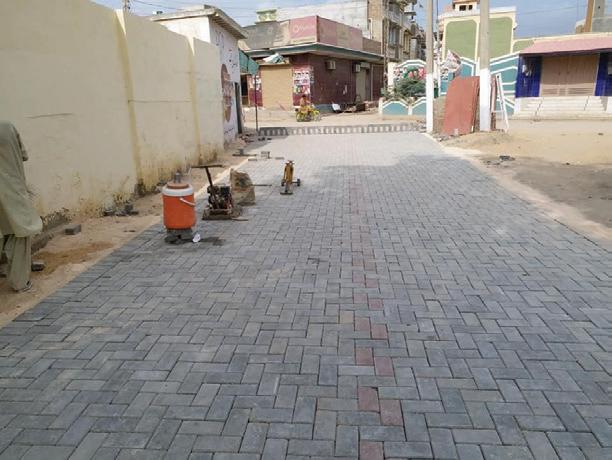
Characteristics of a Well-Maintained Bituminous road
• The roadway cross slope provides effective drainage.
• There are no unsealed cracks, alligator cracks, potholes, washboards, or ruts.
• Little to no ponding follows rain.
• Surface water does not move to the subgrade.
Common Issues


Cracks
Patching pot holes
Patching ruts
Patching corrugations
Base Repairs
Surface Treatment to prevent the road from turning grey
Resurfacing
I 24/03/25
On the concrete roads, the cracks developed on the surface of road are wide, then water and grits are flowed and penetrated into the road sub-grade.
Therefore, such cracks should be well treated immediately.
Common Issues
Repairs of Blown -Ups
Repairs of Cracks
Repairs of Joints
Patch Repairs
Settlement due to
I 24/03/25
For Routine Cleaning of paver blocks
Use a stiff bristle broom and garden hose to scrub and clean the pavers. In areas where you have very dirty pavers (like high traffic zones) you may add in some detergent to the water mix to dislodge dirt from the surface of the pavers. Scrub with push broom and rinse with garden hose.
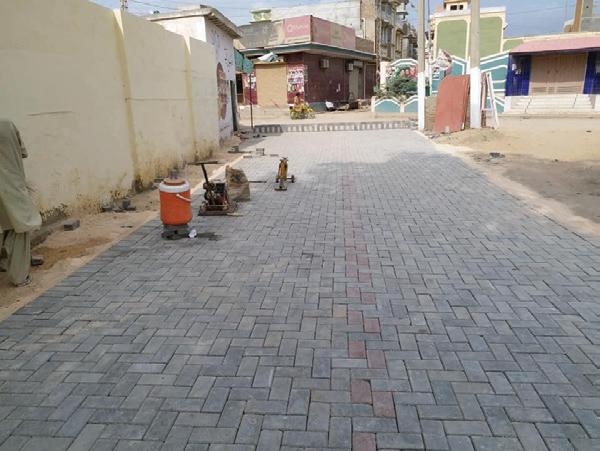
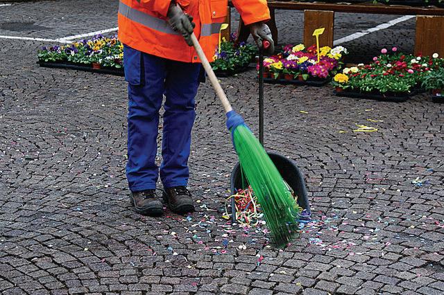
Dustbin Placement
Bus Stops, Along City Streets, Pedestrian Plaza Areas
Frequency of Clearing Dustbin In areas of high footfall
Thrice a Day
Early Morning / Noon / Night
In areas of low footfall
Twice a Day
Spills and Accidents
Intent
Protect the natural environment from contamination from spills resulting from accidents
Steps to clean in case of spills
Identify the nature of the spill
Spills to be contained, cleaned and disposed
Limit migration of contaminants beyond the ROW
In case of contamination of sewer, Inform the respective department
Maintenance Framework
Daily Maintenance
Daily Clearance of dustbins as specified
Monthly / Seasonal Maintenance
Checking for any repairs or maintenance for the dustbins required
Annual Maintenance
Replacement or additional dustbins required
Maintenance Framework
Daily Maintenance
Daily Clearance of dustbins as specified
Monthly / Seasonal Maintenance
Checking for any repairs or maintenance for the dustbins required
Annual Maintenance
Replacement or additional dustbins required
Inspection of storm water drains should be carried out in a proper manner.
The first step is to identify visually the defects and condition of drains that may affect the waterway.
Solid waste management is essential to prevent any blockages to the flow of water.
Storm water Drains


I 24/03/25
1
Issues
Uneven drain bed
Steep invert slope
Solid waste dumping
Spot repairs – e.g. patching, potholes, sinking or broken pavers
• Spot repairs based on inspections
• Replace any broken paver
• Identification and fix the underlying issue rather than depending on surface treatment
Maintenance of the paving material based on the material selected
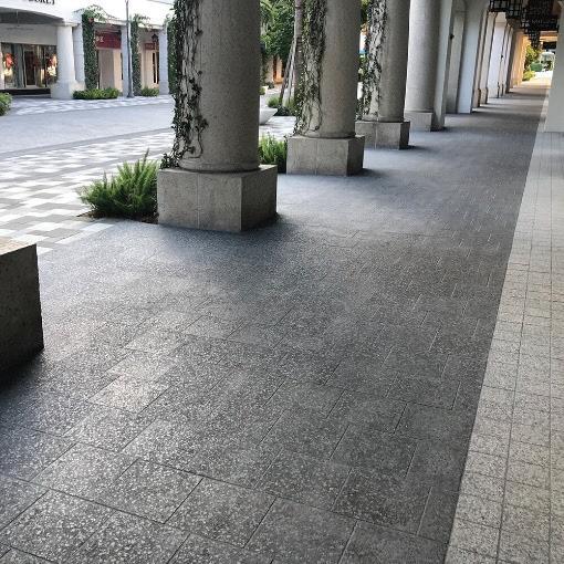


Maintenance Framework
Daily Maintenance
• Sweeping and clearing kerb inlets of debris and solid waste
2 Monthly / Seasonal Maintenance
• Desilting of the drains pre and post-monsoon
• Checking slopes and damages to structure
• Cleaning kerb channel
3 Annual Maintenance I 24/03/25
• Maintaining proper slopes
• Repairing of lining immediately at the commencement of damage
Maintenance of Urban Roads I 19
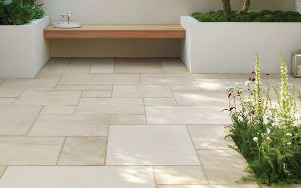
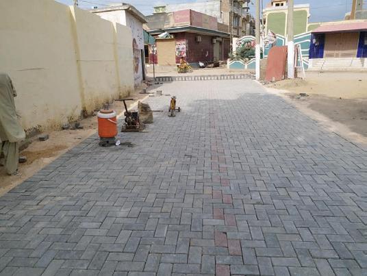
Maintenance is the same as that of concrete paver road
Remove source of rust Granite and Sandstone Paver
Common Maintenance Guideline
Regular Sweeping required
Pressure spray to clean surface
Moulds – Brush area rigorously Dirt – Power hose required


• Daily sweeping and cleaning of surface
/ Seasonal
• Spot repairs – patching, sinking or broken pavers
• Hosing - in case of any spills or stains
• Renewal work if required
Key Issues
Easily damaged on impact Theft
Things to Check
Maintaining sign supports
Washing the sign in case of
Fading signs to be replaced


Key Issue
To be reapplied periodically
Frequency of repainting
Ordinary paint marking
Once every 6 months
Ordinary grade reflector paint
Once every year
Thermoplastic paint
Once in 2-3 years
Things to Check
Remove remnants of old markings
Scrub reflector units after rains
Cut grass around delineators
Washing of signs weekly
• Repairing and checking of signs
• Scrubbing of reflector units
• Reapplying of road marking where required
• Replacement of road signs in case of defect
• Reapplying of road marking where required
Clean furniture as part of routine maintenance
Repaired as per manufacturer
Keep updated inventory of furniture
Respond to issue based on response time


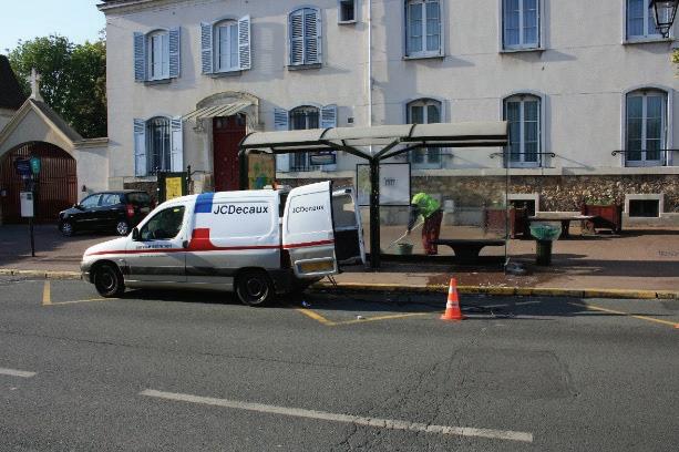
Regular cleaning of seaters
Repair or replacement of damaged infrastructure
Secure sites for safety
or repair broken items
with detergents for various surfaces
• Mobility provides a vital link in the chain of human activity and illuminated roads are an essential requisite for increased mobility.
• Immediate replacement of defective or non-functioning lamps. The IS-1944 recommends that lamps should not be left extinguished for more than one night
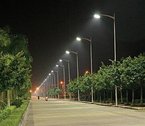


• Cleaning of lamps, luminaries and support systems especially after rains/dusty to ensure no dullness
• Inspection of mains, supply lines, earthings and stability of the support structures
the
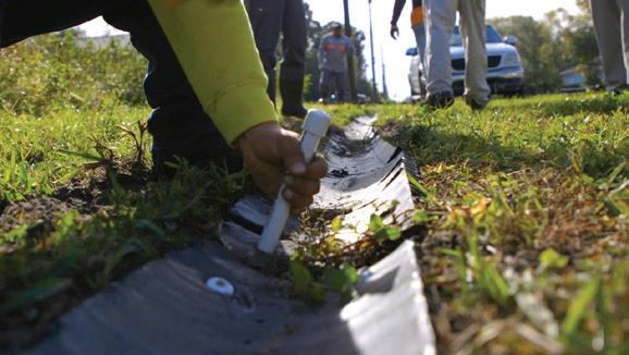
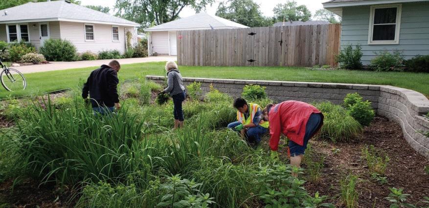
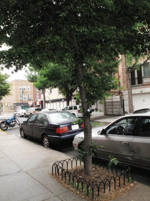
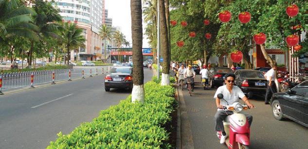
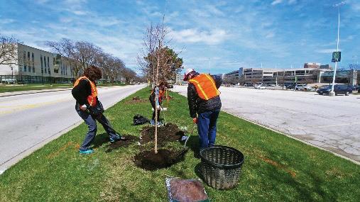
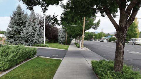

Check for scouring, channelling and erosion
Remove weeds and debris
Check if plants are healthy and dense
Replant gaps and water new plants
Check if soil is not compacted
Aerate soil
After Heavy Rainfall
Remove rubbish, leaves and debris
Top up soil and mulch as necessary
Seasonal / Monthly/ Quarterly
Ensure mulch is below hard surface level
Remove weeds, do not use fertiliser
Annual / Bi-Annual
Test drainage of ponding area
Use inspection well to check underdrain
Necessary access to utilities should be given to minimize maintenance.
Provide enough soil volume to sustain planting and tree growth and avoid conflicts between tree roots and underground utilities.
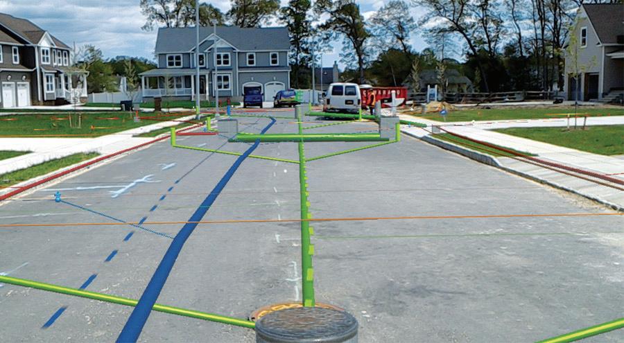


Remove rubbish, leaves and debris
Check health of plant
Check stakes and ties and replace and repair if necessary
Check pit is structurally sound
Check pit drainage by filling with water and monitoring over 24 hours
Concerned division of maintenance agency to be intimated location
At least 72 hours before taking up trenching work at site in order to enable police to divert and regulate traffic
Prior information regarding trenching to be sent to all departments to safeguard their utilities
• Bridges, culverts, ROBs and RUBs should be checked periodically for their soundness and riding surface.
• Spouts should be kept out clean.
Cleaning and clearing
Cleaning and clearing
Cracking repair, erosion repair
Repair of Invert, Construct Culvert at Correct Level and Fall
Cleaning and clearing Reshape/regrade/deepen drain
Erosion Control
Provide New Mitre (Turnout) Drain Construct Outfall Basin
All structures shall be inspected by a competent qualified engineer once a year.
Routine patrol vans/ mobile repair units with all the basic elements and materials required for spot fixing shall be deployed to continuously monitor and undertake spot fixes.




● Annual turn over (in one of the past 5 years) - equal to estimated cost of work (excluding maintenance) – Preferred is 2 to 3 times the estimated cost of work.
● Contractor must have similar experience
○ At least one - not less than 80% of estimated project cost (or)
○ At least two - not less than 50% of estimated project cost (or)
○ At least three - not less than 40% of estimated project cost
● Bidders to submit detailed work and deployment plan.
● SBD must include Operation, Maintenance and Defect Liability Period of 5 Years.
● Line of credit of 10% of contract value
● Bidder should be able to invest min. cash of 25% of contract value
● Only ‘Class A’ contractors to be allowed.

Performance Security
● The Performance Security should be 10% (ten percent) of the total value of contract
● 5 % as Demand Draft / Fixed Deposit in favour of Municipal Commissioner, Nagar Nigam.
● To be returned within 60 days of completion of work
● 5 % deducted from each bill.
● To be returned after completion of the Defect Liability Period (DLP) and Warranty and Maintenance Period (i.e 5 Years)
● Extra performance security
● Upto 10 % below rate on BOQ @ 0.50% per 1% rate.
● In case of bidder quote rates more than 10% below BOQ - extra performance security @ 1% per percentage rate below BOQ


Definition
● Similar work is defined as, experience in substantial completion of -
● Construction of roads in urban areas that includes carriageway, footpaths, streetlights and underground utilities as below:
● Carriageway works should include asphalt/ cement concrete surface with necessary base layers.
● Footpath works include road works involving paver blocks/kerb stone or concrete pathways with roadside landscapes and likewise.
● Underground utilities work, which includes gas, power, sewer, water supply, storm water and telecom works.
For Power line, the Contractor should have similar experience of shifting of power lines from overhead to underground with a minimum capacity of 11KV.
Implementing Complete Streets I 6

● Plant and Machinery should be minimum and only as per the scope of work.
● Contractor’s personnel requirements for Civil & Electrification Works -
● Project Manager, Site Engineer, Architect / Urban Designer, Quantity Surveyor, Soil & Material Engineer, Electrical Engineer and Lab Technician
● Contractor’s personnel requirements for Routine Maintenance –
● Site in charge, Assistant Site in Charge
● Experience and Number for the above will vary from project to project.
Evaluation Chart – Sample from CM GRID, Uttar Pradesh.
• For the work(s) being submitted for consideration as ‘similar work experience’ the Bidder must obtain 80 marks out of 100 for the qualification
Financial proposal will be opened only for those, who qualify.
GPR Survey and Reporting
Dismantling Existing Infrastructure
Tree Removal and Replantation
Road and Footpath Construction
Landscaping and Street Furniture
Utility Shifting and Installation
Safety and Traffic Management
Finalization and Approval
Ground Penetrating Radar (GPR) survey, traffic diversion plan, utility shifting, and stormwater drain levels.
Removal of existing structures such as dividers, footpaths, traffic islands, and utility poles.
Removal of trees, if necessary, with twice the number of trees replanted.
Relaying flexible/rigid pavement, constructing footpaths, intersections, and pedestrian crossings.
Provision of landscaping, street furniture, signage, and lighting
Laying of underground LT/HT cables, utility shifting, and installation of transformers and poles
Preparing and implementing a traffic management plan, ensuring safety during construction
Submission and approval of designs and drawings, including any necessary modifications.
Stakeholder Engagement
Site Preparation
Approval Processes
A kick-off meeting with all relevant stakeholders (e.g., Traffic Police, PWD, Electricity Department) will be arranged.
The contractor will check the topographical survey, mark proposed designs on the ground, and assess the location of underground utilities.
All necessary approvals, including traffic management plans and safety/quality control plans, will be obtained before construction begins.
Execution
Utility Relocation
Roadworks and Landscaping
Power Line Work
The contractor will follow the Good for Construction (GFC) drawings to start the work, adhering to labor regulations and safety standards.
Relocation of utilities will be coordinated with relevant agencies, with costs covered by ULB.
The scope includes excavation, pavement removal, construction of stormwater systems, and installation of road furniture and markings.
Detailed engineering for power lines, including supply, installation, testing, and commissioning of electrical components
Site Clearing and Handover
Defects Liability Period
Routine Maintenance
The contractor will clear the site and submit "As Built Drawings"
Any defects found in the completed works during this period will be rectified by the contractor.
Periodic maintenance will be conducted as per the Standard Operating Procedures (SOP) and Maintenance Manual

● Contractor selection could be shifted to QCBS model to ensure quality
● 80% Technical - 20% Financial
● Minimum of 75% must be scored in technical bid
● Empanelment of technically qualified contractors specially for ‘complete streets’.
● Technical Qualification will be based on prior experience in similar works.
● Only contractors scoring 75% and above can be empanelled
● 3rd Party PMC for each ULB
● Technically qualified empanelled consultants for DPR, Tender Drawings, GFC and site monitoring.
● Itisimportanttoensurethatthebiddocumentislegibleandwellform atted
● Toensureclarityandallowforproperreviewofthedocumentprior tobidding
● Ensure that legible drawing should be uploaded with bidding document
● Ensure that all the technical specification should be as per MoRTH 2019, IRC 58, IRC 37, and other relevant IS / IRC codes
● It is important to ensure that the bid document is legible and well formatted
● To ensure clarity and allow for proper review of the document prior to bidding
● Ensure that legible drawing should be uploaded with bidding document
● Ensure that all the technical specification should be as per MoRTH 2019, IRC 58, IRC 37, and other relevant IS / IRC codes
The BOQ should be split into the following heads :
• Cost of Upgradation of Road
• Cost of Footpaths
• Cost of Utility Ducts
• Cost of Storm Water Drainage
• Cost of Landscape / Horticulture Works
• Cost of Street lighting
• Cost of all other Minor Works
• Cost of all other Major Works
Additional components of the summary sheet :
• Basic road details should be mentioned on the summary sheet
• Highlights of each subdivision should also be mentioned – to help compare and review costs across multiple road projects.
• Additional cost considerations such as GST, Labour Cess, Contingency, etc. – these will vary from state to state and between executing agencies.
Additional components of the summary sheet :
• Basic road details should be mentioned on the summary sheet
• Highlights of each subdivision should also be mentioned – to help compare and review costs across multiple road projects.
• Additional cost considerations such as GST, Labour Cess, Contingency, etc. – these will vary from state to state and between executing agencies.
• It is important to consider all layers required for the relaying of a road.
• Even where the carriageway is not being relayed, some amount of sub layers may be required for areas where patch-work or road cutting is to be done.
• The composition/specifications of the sublayers must be aligned with the details mentioned in the Executive Summary
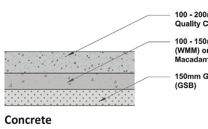
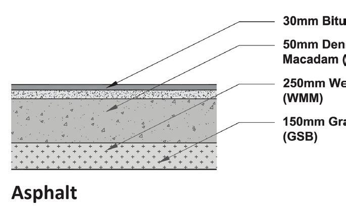
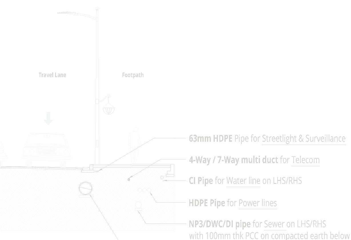
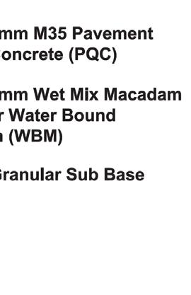
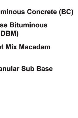
Recommended specifications for utilities as per Tender SURE is as follows :
• Water Supply : CI Pipe
• Power Lines : HDPE Pipe
• Sewer Line : NP3 / Ductile Iron (DI) / Double Wall Corrugated (DWC)
• Storm Water : NP3 pipe
• Telecom : 7-way / 4-way multiduct
• Streetlight : 63mm HDPE Pipe
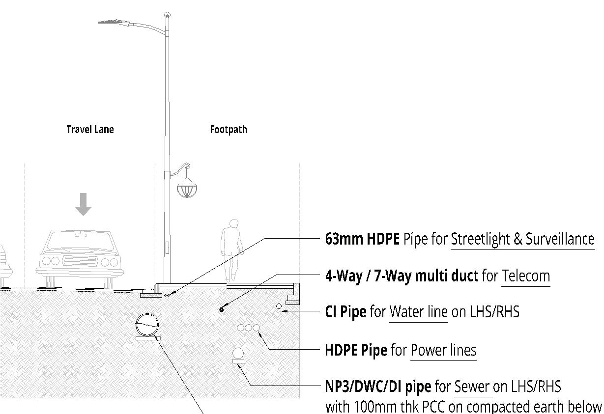
Recommended specifications for utilities as per Tender SURE is as follows :
• Water Supply : CI Pipe
• Power Lines : HDPE Pipe
• Sewer Line : NP3 / Ductile Iron (DI) / Double Wall Corrugated (DWC)
• Storm Water : NP3 pipe
• Telecom : 7-way / 4-way multiduct
• Streetlight : 63mm HDPE Pipe
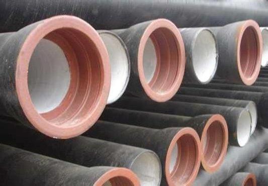
used diameters : 150 mm
Recommended specifications for utilities as per Tender SURE is as follows :
• Water Supply : CI Pipe
• Power Lines : HDPE Pipe
• Sewer Line : NP3 / Ductile Iron (DI) / Double Wall Corrugated (DWC)
• Storm Water : NP3 pipe
• Telecom : 7-way / 4-way multiduct
• Streetlight : 63mm HDPE Pipe
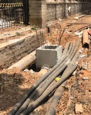
Commonly used diameters : 200 mm Usually 2 or more on each side
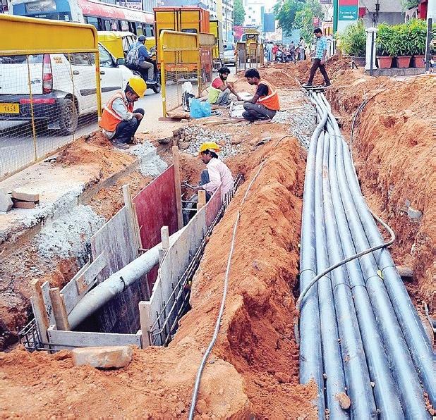
Recommended specifications for utilities as per Tender SURE is as follows :
• Water Supply : CI Pipe
• Power Lines : HDPE Pipe
• Sewer Line : NP3 / Ductile Iron (DI) / Double Wall Corrugated (DWC)
• Storm Water : NP3 pipe
• Telecom : 7-way / 4-way multiduct
• Streetlight : 63mm HDPE Pipe
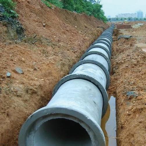
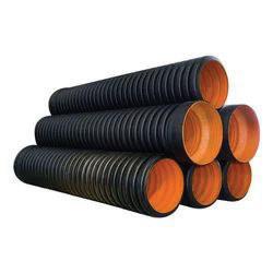
Commonly used diameters : 250 - 300 mm
Recommended specifications for utilities as per Tender SURE is as follows :
• Water Supply : CI Pipe
• Power Lines : HDPE Pipe
• Sewer Line : NP3 / Ductile Iron (DI) / Double Wall Corrugated (DWC)
• Storm Water : NP3 pipe
• Telecom : 7-way / 4-way multiduct
• Streetlight : 63mm HDPE Pipe
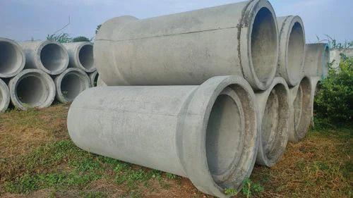
Recommended specifications for utilities as per Tender SURE is as follows :
• Water Supply : CI Pipe
• Power Lines : HDPE Pipe
• Sewer Line : NP3 / Ductile Iron (DI) / Double Wall Corrugated (DWC)
• Storm Water : NP3 pipe
• Telecom : 7-way / 4-way multiduct
• Streetlight : 63mm HDPE Pipe
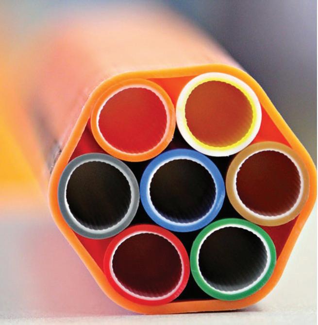
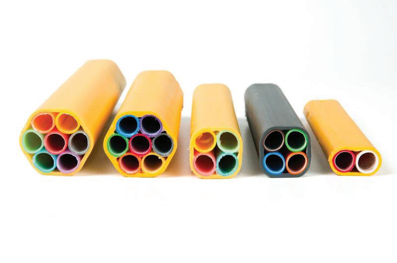
Recommended specifications for utilities as per Tender SURE is as follows :
• Water Supply : CI Pipe
• Power Lines : HDPE Pipe
• Sewer Line : NP3 / Ductile Iron (DI) / Double Wall Corrugated (DWC)
• Storm Water : NP3 pipe
• Telecom : 7-way / 4-way multiduct
• Streetlight : 63mm HDPE Pipe
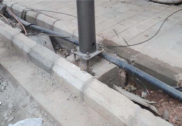
Recommended specifications for utilities as per Tender SURE is as follows :
• Water Supply : CI Pipe
• Power Lines : HDPE Pipe
• Sewer Line : NP3 / Ductile Iron (DI) / Double Wall Corrugated (DWC)
• Storm Water : NP3 pipe
• Telecom : 7-way / 4-way multiduct
• Streetlight : 63mm HDPE Pipe
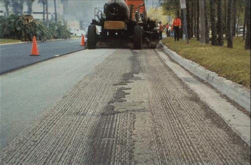
• Scarifying
• Dismantling
• (Rubber Moulded) Kerb Stones
• Drain Kerbs
• Catchpits and Grating for Storm Water
• Tactile Pavers
• High Strength Pavers for Parking (80mm)
• Landscape
• Shuttering
• Dustbins / Seating / other design elements as required
• Lighting
• Streetlight cables (63mm HDPE Pipe)
• Signage
• Barricading
• Bollards
• FRP Manhole Covers
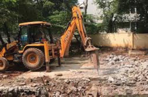
• Scarifying
• Dismantling
• (Rubber Moulded) Kerb Stones
• Drain Kerbs
• Catchpits and Grating for Storm Water
• Tactile Pavers
• High Strength Pavers for Parking (80mm)
• Landscape
• Shuttering
• Dustbins / Seating / other design elements as required
• Lighting
• Streetlight cables (63mm HDPE Pipe)
• Signage
• Barricading
• Bollards
• FRP Manhole Covers
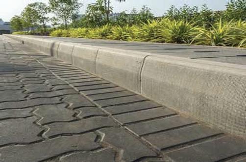
• Scarifying
• Dismantling
• (Rubber Moulded) Kerb Stones
• Drain Kerbs
• Catchpits and Grating for Storm Water
• Tactile Pavers
• High Strength Pavers for Parking (80mm)
• Landscape
• Shuttering
• Dustbins / Seating / other design elements as required
• Lighting
• Streetlight cables (63mm HDPE Pipe)
• Signage
• Barricading
• Bollards
• FRP Manhole Covers
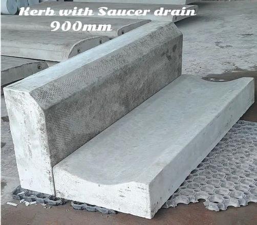
• Scarifying
• Dismantling
• (Rubber Moulded) Kerb Stones
• Drain Kerbs
• Catchpits and Grating for Storm Water
• Tactile Pavers
• High Strength Pavers for Parking (80mm)
• Landscape
• Shuttering
• Dustbins / Seating / other design elements as required
• Lighting
• Streetlight cables (63mm HDPE Pipe)
• Signage
• Barricading
• Bollards
• FRP Manhole Covers
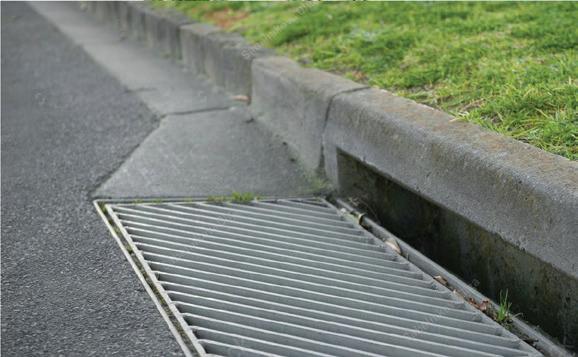



• Scarifying
• Dismantling
• (Rubber Moulded) Kerb Stones
• Drain Kerbs
• Catchpits and Grating for Storm Water
• Tactile Pavers
• High Strength Pavers for Parking (80mm)
• Landscape
• Shuttering
• Dustbins / Seating / other design elements as required
• Lighting
• Streetlight cables (63mm HDPE Pipe)
• Signage
• Barricading
• Bollards
• FRP Manhole Covers
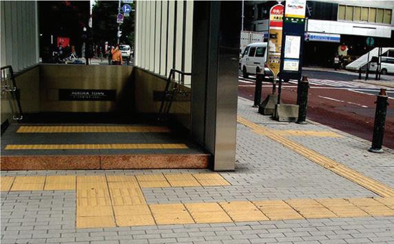
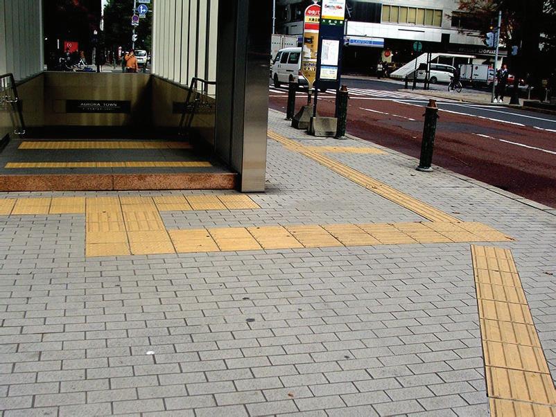
• Scarifying
• Dismantling
• (Rubber Moulded) Kerb Stones
• Drain Kerbs
• Catchpits and Grating for Storm Water
• Tactile Pavers
• High Strength Pavers for Parking (80mm)
• Landscape
• Shuttering
• Dustbins / Seating / other design elements as required
• Lighting
• Streetlight cables (63mm HDPE Pipe)
• Signage
• Barricading
• Bollards
• FRP Manhole Covers


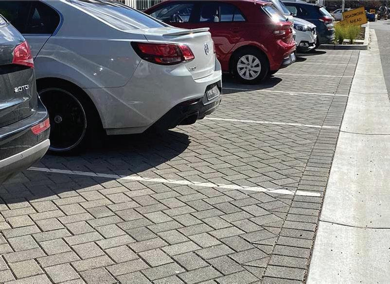
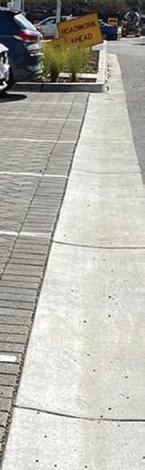

• Scarifying
• Dismantling
• (Rubber Moulded) Kerb Stones
• Drain Kerbs
• Catchpits and Grating for Storm Water
• Tactile Pavers
• High Strength Pavers for Parking (80mm concrete)
• Landscape
• Shuttering
• Dustbins / Seating / other design elements as required
• Lighting
• Streetlight cables (63mm HDPE Pipe)
• Signage
• Barricading
• Bollards
• FRP Manhole Covers
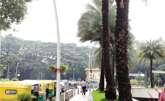
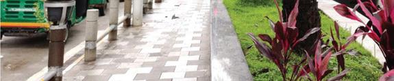

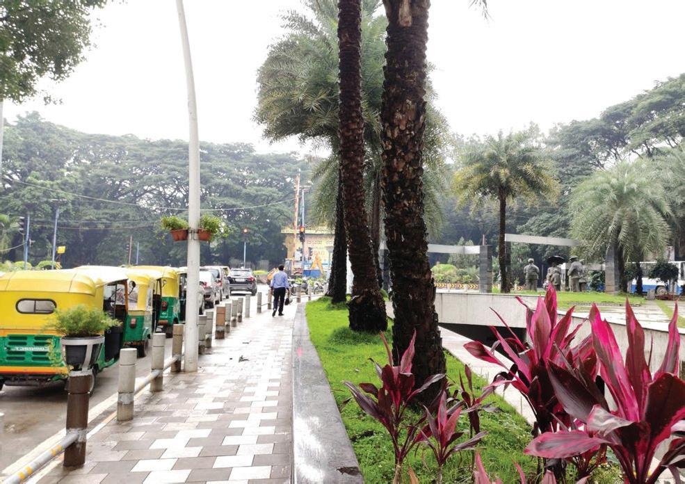


• Scarifying
• Dismantling
• (Rubber Moulded) Kerb Stones
• Drain Kerbs
• Catchpits and Grating for Storm Water
• Tactile Pavers
• High Strength Pavers for Parking (80mm concrete)
• Landscape
• Shuttering
• Dustbins / Seating / other design elements as required
• Lighting
• Streetlight cables (63mm HDPE Pipe)
• Signage
• Barricading
• Bollards
• FRP Manhole Covers

• Scarifying
• Dismantling
• (Rubber Moulded) Kerb Stones
• Drain Kerbs
• Catchpits and Grating for Storm Water
• Tactile Pavers
• High Strength Pavers for Parking (80mm concrete)
• Landscape
• Shuttering
• Dustbins / Seating / other design elements as required
• Lighting
• Streetlight cables (63mm HDPE Pipe)
• Signage
• Barricading
• Bollards
• FRP Manhole Covers

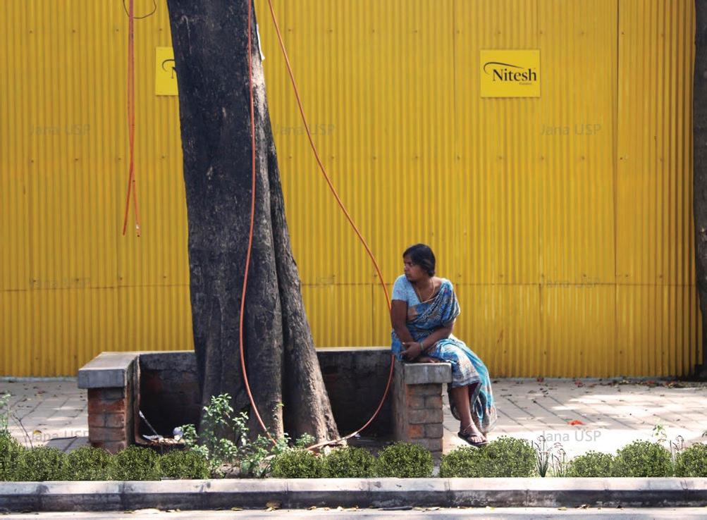

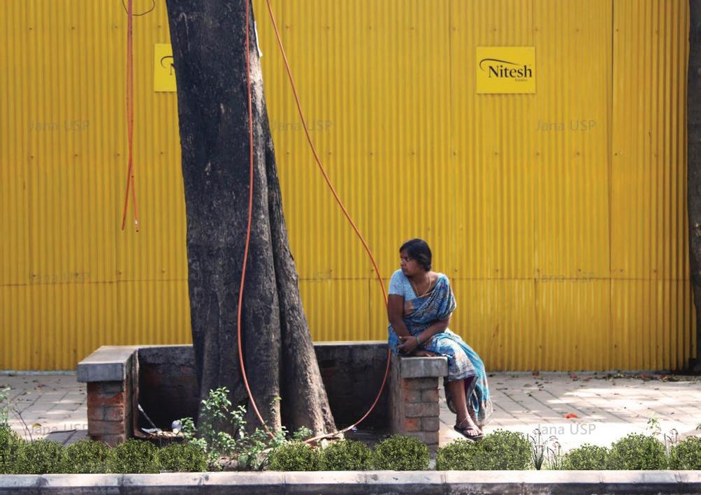
• Scarifying
• Dismantling
• (Rubber Moulded) Kerb Stones
• Drain Kerbs
• Catchpits and Grating for Storm Water
• Tactile Pavers
• High Strength Pavers for Parking (80mm concrete)
• Landscape
• Shuttering
• Dustbins / Seating / other design elements as required
• Lighting
• Streetlight cables (63mm HDPE Pipe)
• Signage
• Barricading
• Bollards
• FRP Manhole Covers
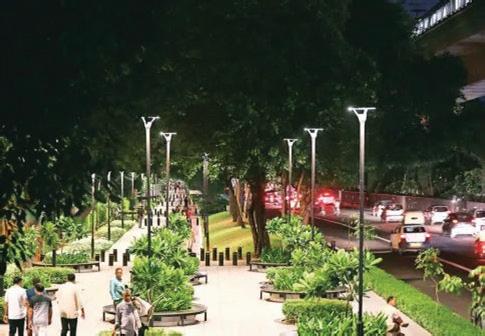
• Scarifying
• Dismantling
• (Rubber Moulded) Kerb Stones
• Drain Kerbs
• Catchpits and Grating for Storm Water
• Tactile Pavers
• High Strength Pavers for Parking (80mm concrete)
• Landscape
• Shuttering
• Dustbins / Seating / other design elements as required
• Lighting
• Streetlight cables (63mm HDPE Pipe)
• Signage
• Barricading
• Bollards
• FRP Manhole Covers
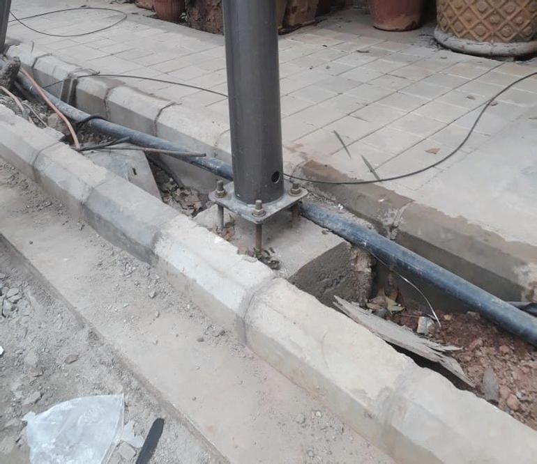
• Scarifying
• Dismantling
• (Rubber Moulded) Kerb Stones
• Drain Kerbs
• Catchpits and Grating for Storm Water
• Tactile Pavers
• High Strength Pavers for Parking (80mm concrete)
• Landscape
• Shuttering
• Dustbins / Seating / other design elements as required
• Lighting
• Streetlight cables (63mm HDPE Pipe)
• Signage
• Barricading
• Bollards
• FRP Manhole Covers
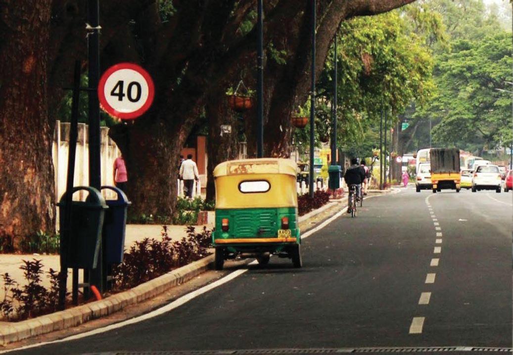
• Scarifying
• Dismantling
• (Rubber Moulded) Kerb Stones
• Drain Kerbs
• Catchpits and Grating for Storm Water
• Tactile Pavers
• High Strength Pavers for Parking (80mm concrete)
• Landscape
• Shuttering
• Dustbins / Seating / other design elements as required
• Lighting
• Streetlight cables (63mm HDPE Pipe)
• Signage
• Barricading
• Bollards
• FRP Manhole Covers
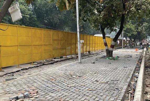
• Scarifying
• Dismantling
• (Rubber Moulded) Kerb Stones
• Drain Kerbs
• Catchpits and Grating for Storm Water
• Tactile Pavers
• High Strength Pavers for Parking (80mm concrete)
• Landscape
• Dustbins / Seating / other design elements as required
• Lighting
• Streetlight cables (63mm HDPE Pipe)
• Signage
• Barricading
• Bollards
• FRP Manhole Covers
• Shuttering

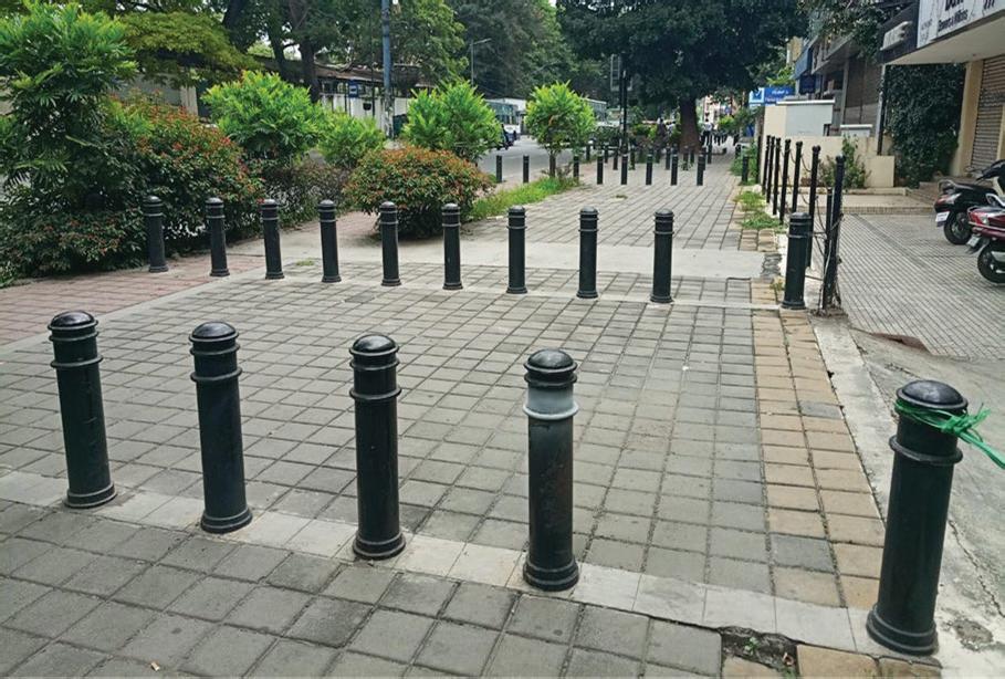
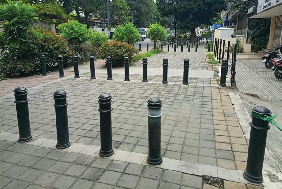
• Scarifying
• Dismantling
• (Rubber Moulded) Kerb Stones
• Drain Kerbs
• Catchpits and Grating for Storm Water
• Tactile Pavers
• High Strength Pavers for Parking (80mm concrete)
• Landscape
• Dustbins / Seating / other design elements as required
• Lighting
• Streetlight cables (63mm HDPE Pipe)
• Signage
• Barricading
• Bollards
• FRP Manhole Covers
• Shuttering
• Scarifying
• Dustbins / Seating / other design elements as required

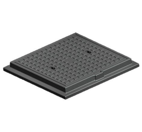
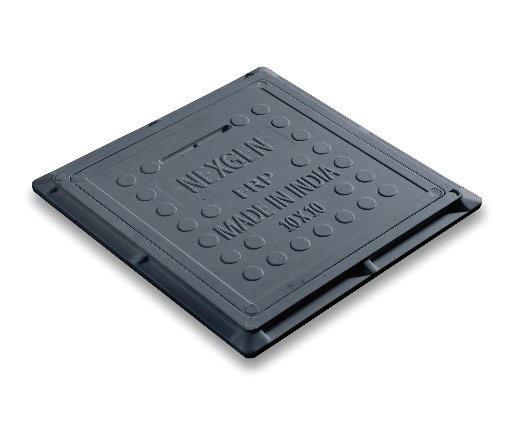
• Dismantling
• (Rubber Moulded) Kerb Stones
• Drain Kerbs

• Catchpits and Grating for Storm Water
• Tactile Pavers
• High Strength Pavers for Parking (80mm concrete)
• Landscape
• Shuttering

• Lighting
• Streetlight cables (63mm HDPE Pipe)
• Signage
• Barricading
• Bollards
• Manhole Covers