STRUCTURE STRUCTURE NCSEA | CASE | SEI
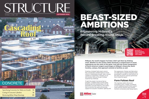
Cascading
SEPTEMBER 2026
BEAST-SIZED AMBITIONS
SEPTEMBER 2026
NCSEA | CASE | SEI
Engineering MrBeast’s Record-breaking Sound Stage
Scan for a downloadable copy of the full case study.
MrBeast, the world’s biggest YouTuber, didn’t get there by thinking small. Whether it’s the world’s tallest dominoes or largest bowl of cereal, superlatives are the name of the game. And with the recent inauguration of North America’s largest sound stage on MrBeast’s Greenville, North Carolina, campus, that approach extends to facilities as well. Creating a football field-sized, columnfree, acoustically isolated space on short notice is challenging enough. Add a ceiling capable of supporting a hanging car at any location and you’ve got a unique engineering challenge.
CONCRETE INSIDE: Specifying Concrete for Slabs-on-Grade 10 Curing of Concrete Cylinders 16 Reviewing Rebar Shop Drawings 20
To get the project moving as fast as possible, a prefabricated, arched metal building was first erected atop a 10' tall perimeter Concrete Masonry Unit (CMU) wall to enclose the space and provide support for acoustic insulation, lighting and
fire suppression. Design and fabrication of a light grid to support hanging loads proceeded in parallel so that erection of the steel structure could be performed from inside the space.
Form Follows Roof The engineer, Collins Structural Consulting (CSC), initially considered a more traditional portal frame system using vertical columns and inclined, moment-connected wide flange beams.
Read more
Raise the Roof
But with a 150-foot clear span, the frames would have been very heavy and would cut into the building’s usable space. “So as an alternative, we started looking at a frame that roughly followed the shape of the roof,” said Scott Collins, Principal at CSC. “And then we applied load to the frame and let it bend to whatever shape it wanted. Then we asked: how do we push it back into shape so we can carry the load we need?” The curved roof approximates the shape of an arch but is not parabolic. That, along with the need to support heavy, potentially unbalanced loads, meant the frame would need to resist large moments. Rather than design heavier, deeper members to resist those moments, a set of overlapping tension rods were introduced. The rods ran below the frame ribs in regions with positive moment (near the midspan of each half frame) and above the ribs in regions with negative moment (near the supports).
HSS Frame Rib Splice with Shuriken Tension rod Gusset with Shuriken
An elevation of one of the frame ribs.
The result was a frame that behaved like a three-pin tied arch. Tie forces from the frame were resolved by running rebar through the slab across the full width of the building, with the bars hooked around shear lugs at each base plate.
Material Efficiency at Speed Domestically produced 10-inch square HSS from Atlas Tube was used for the frame ribs. “When you’re dealing with long shapes with little bracing, HSS is going to be a lot stronger than wide flanges,” said Collins. By relying on arch action and using HSS for the main
A frame being erected.
Kinked, double shear Shuriken splices after fabrication. The Shuriken were staggered to avoid conflicts within the HSS members. Inset: Finite element modeling of a kinked connection.
members, steel tonnage was reduced from approximately 480 tons to 280 tons, yielding significant cost savings. To avoid the complexity and lead time associated with curved members, the frames were constructed from multiple short, mitered sections. Welding the connections between these sections was a non-starter due to the height of the structure and the complexity of the angled joints. Instead, the Shuriken® Structural Nut Keeper was used to allow field bolting from the exterior of the HSS, with connections designed in double shear to keep them compact. Though the connections were similar to typical HSS column splices, the kinks introduced complexity. Splice plates for the vertical walls of the HSS were cut in a chevron shape, whereas those at the top and bottom were bent to match the angle of the joint. The use of irregularly-shaped plates to transmit combined loading through an angled joint required finite element modeling for analysis. The fabricator, North State Steel, and erector, ASPE South, have become the go-to choices for MrBeast thanks to their ability to turn projects around at high speed. The use of straight, mitered sections to form the frames simplified their fabrication but also increased the number of pieces, which made test fitting essential. “We had to do a lot of fitting up and pulling out. Occasionally ream a hole to tweak the fit-up. So there was a process, but it wasn’t extremely difficult fabrication,” said JD Morgan, President of North State Steel.
Each frame was partially assembled on the ground: the two end sections were assembled and erected first, then the center section was lifted into place. With the center section in place, the protruding splice plates were joined using kinked covers made of HSS cut lengthwise.
Now You’re Torquing Filler beams running between each set of frames were designed for 250 pounds per linear foot (plf) vertical and 25 plf horizontal. To capture all possible load effects, the engineering team had to consider no less than 254 load cases. The unbalanced loads induced reversible loads in many of the frame rib joints, necessitating the use of slip-critical bolts. Bolts were a mix of 1" grade A490 and 3/4" grade A325 bolts, with the structure using nearly 10,000 Shuriken for the onesided HSS connections. The ability to use large diameter fasteners and make slip-critical connections are features that distinguish Shuriken from other one-sided fasteners. Pretensioning proceeded after each frame rib was erected and the tie rods were tensioned. “Once everything was at the correct elevation, in line, true, plumb and square, we torqued everything down,” said Travis Freeman, EVP with ASPE South. DuraSquirt DTIs were used to allow visual inspection of the bolts, accelerating inspection compared to traditional DTIs, which require feeler gauges to verify proper compression.
Building a World of Pure Imagination The new sound stage will be the site of untold creativity for years. Those working to produce incredible scenes within it may not realize that an equal feat of creativity hovers just overhead. The tie rods that were included to resist moments in the frame ribs brought an additional benefit: with each tie rod having opposite threads at its ends, they could be tensioned as needed to fine tune the curvature of each frame rib. The design originally called for clevises, but long lead times lead the team to opt for solid 6" pins instead. The gussets that received the pins and rods were very long due to the shallow angle between the frame ribs and the rods, so cutouts — including some matching the MrBeast A gusset plate sporting logo — were included to the MrBeast logo. reduce weight.
Partners: Owner: Beast Productions Structural Engineer: Collins Structural Consulting Fabricator: North State Steel Erector: ASPE South HSS and Shuriken: Atlas Tube
Visit atlastube.com/ambition to try Atlas Tube’s complimentary HSS design tools or discuss your design ambitions with our engineering experts.
ADVERTISER index
Please support these advertisers
ACEC.................................................................................... 49 Allen Business Advisors.................................................... 31 ASCE.................................................................................... 6 Atlas...................................................................................... Cover Gatefold Adhesives Technology..................................................... 13 Computers & Structures Inc...................................................... Back Cover CTS Cement........................................................................ 33 DEWALT............................................................................... 5 DuroTerra............................................................................. 27 ENERCALC......................................................................... 9 IES.......................................................................................... 26 INDUCTA .......................................................................... 12 MAPEI.................................................................................. Inside Back Cover MAX USA CORP............................................................... 11 Premiere Concrete............................................................ 23 PS=Ø.................................................................................... 3 Simpson Strong-Tie........................................................... 15 Simpson Strong-Tie........................................................... 29 Wells Concrete.................................................................. 7
STRUCTURE
®
CIRCULATION
subscriptions@structuremag.org
EDITORIAL BOARD Chair John A. Dal Pino, S.E. Claremont Engineers Inc., Oakland, CA chair@STRUCTUREmag.org Kevin Adamson, PE Structural Focus, Gardena, CA Marshall Carman, PE, SE Schaefer, Cincinnati, Ohio Erin Conaway, PE AISC, Phoenix, AZ Sarah Evans, PE Walter P Moore, Houston, TX Steven Judd Interstate Brick, West Jordan, Utah, and H.C. Muddox, Sacramento, California Linda M. Kaplan, PE Pennoni, Pittsburgh, PA Jessica Mandrick, PE, SE, LEED AP Gilsanz Murray Steficek, LLP, New York, NY Brian W. Miller Cast Connex Corporation, Davis, CA
September 2026 Digital Issue Available Only at
STRUCTUREmag.org
Evans Mountzouris, PE Retired, Milford, CT Kenneth Ogorzalek, PE, SE KPFF Consulting Engineers, San Francisco, CA (WI) John “Buddy” Showalter, PE International Code Council, Washington, DC Eytan Solomon, PE, LEED AP TYLin, New York, NY
EDITORIAL STAFF Executive Editor Alfred Spada Publication of any article, image, or advertisement in STRUCTURE® magazine does not constitute endorsement by NCSEA, CASE, SEI, the Publisher, or the Editorial Board. Authors, contributors, and advertisers retain sole responsibility for the content of their submissions. STRUCTURE magazine is not a peer-reviewed publication. Readers are encouraged to do their due diligence through personal research on topics.
ADVERTISEMENT–For Advertiser Information, visit STRUCTUREmag.org
aspada@ncsea.com
Managing Editor Shannon Wetzel swetzel@structuremag.org
MARKETING & ADVERTISING SALES Senior Director for Business Development & Marketing Monica Shripka Tel: 847-900-9734 monica.shripka@STRUCTUREmag.org
STRUCTURE magazine (ISSN 1536 4283) is published monthly by The ®
National Council of Structural Engineers Associations (a nonprofit Association), 20 N. Wacker Drive, Suite 750, Chicago, IL 60606 312.649.4600. Periodical postage paid at Chicago, Il, and at additional mailing offices. STRUCTURE magazine, Volume 33, Number 9, © 2026 by The National Council of Structural Engineers Associations, all rights reserved. Subscription services, back issues and subscription information tel: 312-649-4600, or write to STRUCTURE magazine Circulation, 20 N. Wacker Drive, Suite 750, Chicago, IL 60606.The publication is distributed to members of The National Council of Structural Engineers Associations through a resolution to its bylaws, and to members of CASE and SEI paid by each organization as nominal price subscription for its members as a benefit of their membership. Yearly Subscription in USA $75; $40 For Students; Canada $90; $60 for Canadian Students; Foreign $135, $90 for foreign students. Editorial Office: Send editorial mail to: STRUCTURE magazine, Attn: Editorial, 20 N. Wacker Drive, Suite 750, Chicago, IL 60606. POSTMASTER: Send Address changes to STRUCTURE magazine, 20 N. Wacker Drive, Suite 750, Chicago, IL 60606. STRUCTURE is a registered trademark of the National Council of Structural Engineers Associations (NCSEA). Articles may not be reproduced in whole or in part without the written permission of the publisher.
SEPTEMBER 2026
3
Contents
S E P T E M B E R 2 0 26
THE CASCADING TIMBER ROOF OF THE BLOOMBERG STUDENT CENTER
44
By Florian Meier, Shamil Lallani, and Christian Rieser
Complex mass timber interacts with a transparent envelope.
F E A T U R E S LESSONS FROM BOWSTRING TRUSS FAILURES IN CHICAGO
By Mohit Rathi
Modern design tools and methods help structural engineers reinforce and repair bow-truss buildings.
34 38
MAINTAINING THE STATE OF THE ART
By Robert E. Evans III, PE, and Alec S. Zimmer, PE ADVERTISEMENT–For Advertiser Information, visit STRUCTUREmag.org
A U.S. Army Arsenal warehouse building was adapted into a life science laboratory and office building.
The Latest Standard for Flood-Resistant Design ASCE/SEI 24: Flood Resistant Design and Construction Essential guidance for engineers, floodplain managers, and building officials working in flood-prone areas. Available on AMPLIFY, in print, and as an e-book.
Join us for this Webinar series in September! ASCE/SEI 24-24 Series • Sep 2: The Big Shifts in ASCE 24‑24 • Sep 9: What Actually Changes in Practice • Sep 23: ASCE 24‑24: Worked Examples
4
STRUCTUREmagazine
Visit asce.org/asce24 to access the standard and register for upcoming webinars.
SCAN TO LEARN MORE
INDUSTRY LEADER IN CODE APPROVED ANCHORING SYSTEMS CHEMICAL ANCHORING
WEDGE ANCHORS
PURE220+™
DOMESTIC POWER-STUD®+ SD1
APPROVALS
APPROVALS
I
NC
SM
IC REGI
LI
O ATI
N
QU
D CO
A
FIC
SE
• Compliant with NSF/ANSI 61 for drinking water system components F120 F180
• ICC-ES ESR-2966 Masonry
E
SE
ION ZO
TE
NS
KE
C
• Conforms to requirements of ASTM C881 including C882 and AASHTO M235, Types I, II, IV and V, Grade 3, Classes B & C
ET
N
O
R
FIC ATI
E
ET
R
TE
LI
• ICC-ES ESR-2818 Concrete ON
C
QU
CRA
A
• Cracked and uncracked concrete including seismic and wind loading
NE
D CONC
IC REGI
CRA
KE
SM
ON
ION ZO NE
NS
I
• ICC-ES ESR-5144 Concrete
• Recognition in cracked and uncracked concrete including seismic and wind loading (Category 1 Anchors) • FM & UL listings: www.DEWALT.com
• Department of Transportation listings
STATE-OF-THE-ART STRUCTURAL DESIGN SOFTWARE DESIGN
Code-compliant anchor designs according to ACI 318-19, ACI 318-14, and CAS A23.3-14
DOCUMENT
DOWNLOAD THE FULL FREE SUITE AT DEWALT.COM/DDA
Comprehensive design calculations with numerous reporting options
COMPARE
Compare multiple anchor types, sizes, and brands at a glance to efficiently evaluate design requirements
ANCHOR
Strengthen your design with a full catalog of DEWALT® anchors
©2026 DEWALT.
C O L U M N S a n d D E PA RT M E N TS
8 Editorial
Safety: The Condition of Being Safe From Undergoing or Causing Hurt, Injury, or Loss By Glenn Bell, PE, SE
10
Structural Design
Specifying High Quality Concrete for Slabs-on-Grade By Dave Flax
16
Structural Design
Initial Curing of Concrete Cylinders: A Sustainable Lever Hiding in Plain Sight By Mike Hernandez, PE, Bryan Birdwell, Zachoriah Ballard, PE, and Jason Wimberly, PE
18 Structural Design
Thermal Restraint and Fire Protection of Structures By Richard Way, PE, SE
32 In Focus
Reinforcing Bars as Anchorage By Matt Blessent
50 In Focus
Inspiring the Next Generation of Structural Engineers By Jillian C. Kilker
52
Structural Forum Engineer or Principal? By Kevin Chamberlain, PE, SE
62 NCSEA Summit
Packed Summit Offers Education to Put Into Action
66
Structural Forum A “Dirty Secret” of Structural Engineering By Scott Hill
20
Structural Design
24
A Practical Guide to Reviewing Rebar Shop Drawings By Nelly R Sanchez, PE
24 InSights
From Weeks to Days: Advancements in Electrochemical Realkalization for Historic Concrete By Gina Crevello, Paul Noyce, and Chris Ball
30 Business Practices
Professional Liability Insurance Myth-Busting: Part 1 By Karen Erger
In Every Issue 3 Advertiser Index 54 SE News 56 CASE in Point 58 SEI Update 60 NCSEA News
6
STRUCTUREmagazine
50
66
WELLS // BUILD WITHOUT LIMITS WELLS // BUILD WITHOUT LIMITS
Transform the way you build. Transform Transform the the way way you you build. build.
For those ready to build without limits, Wells offers boundary-pushing prefabricated building
systems that can transform bold ideas into spaces that stand the test of time. G E T I N S P I R E D AT W E L L S . B U I L D
For those ready to build without limits, Wells offers boundary-pushing prefabricated building For thosethat ready build without offers that boundary-pushing prefabricated building systems cantotransform boldlimits, ideas Wells into spaces stand the test of time. systems that can transform bold ideas into spaces that stand the test of time. G E T I N S P I R E D AT W E L L S . B U I L D G E T I N S P I R E D AT W E L L S . B U I L D
EDITORIAL Safety: The Condition of Being Safe From Undergoing or Causing Hurt, Injury, or Loss By Glenn Bell, PE, SE
T
he title of this editorial is drawn directly from Merriam-Webster’s definition of safety. Reading those words brings sobering focus to the continuous responsibility we bear as structural engineers when we pledge to hold paramount the health, safety, and welfare of the public. I first witnessed the devastating human toll of catastrophic structural failure while investigating the 1981 walkways collapse at the Hyatt Regency Hotel in Kansas City. As a young engineer, I was harsh in my criticism of those I held responsible. Yet the intervening decades have brought humility and a profound realization: if our vigilance lapses, Hyatt-like failures can happen on any of our watches. Our professional pledge extends far beyond the boundaries of our individual engineering projects. We have a collective duty to study structural failures and safety concerns of all types, share those insights, and advocate for systemic changes aimed at preventing public safety disasters. How effectively have we learned from failures and effected meaningful change in the 45 years since the Hyatt Regency collapse? Looking specifically at building failures unrelated to natural hazards or intentional destruction, our record is mixed. While we have made important progress in certain areas, we see that root causes recur—we are not fully converting lessons learned into improved practice. • Progress is too often episodic. In the wake of a catastrophic failure, concerted efforts focus on identifying the causes and directing resources toward improvements in codes, standards, practices to improve building safety. However, public support often wanes as the memory of the event fades. • Procedural breakdowns remain difficult to address. The progress made in incorporating technical and scientific lessons into codes and standards is laudable. But we’ve made comparably less progress in dealing with procedural issues: weak enforcement, inadequate quality control and assurance, human error, and deliberate shortcuts around established procedures. • Impediments to information-sharing restrict learning. Many forensic investigations are conducted by experts 8 STRUCTURE magazine
We have a collective duty to study structural failures and safety concerns of all types, share those insights, and advocate for systemic changes aimed at preventing public safety disasters. retained for litigation. Cases frequently settle out of court under non-disclosure agreements. As a result, valuable technical lessons remain buried in sealed files. • Early warning signs are missed or ignored. Structural malperformance often manifests before catastrophic collapse. If we systematically applied knowledgeable attention to signs of change in structural performance and took timely corrective action, many failures could be averted. Two major developments since the Hyatt Regency collapse directly address these systemic challenges: • The National Construction Safety Team (NCST) Act: Signed into law in 2002, the Act empowers NIST to investigate building failures resulting in—or having the potential for—loss of life. NIST identifies the most likely technical causes of a failure and recommends improvements to codes, standards and practices, and any appropriate research. Crucially, the Act mandates that NIST track recommendation implementation and report progress annually to Congress, driving sustained improvements. • Collaborative Reporting for Safer Structures (CROSS/CROSS-US): Introduced in the UK in 2000 and launched in the U.S. by SEI in 2019, CROSS publishes anonymous reports on less-than-catastrophic failures, near misses, and safety concerns and provides expert commentary. By capturing frequent, unencumbered precursor events, CROSS enables the industry to address risks before they escalate into catastrophic failures. Structural safety is fundamentally a human and societal obligation. As our profession
addresses imperatives for sustainability, resilience, and innovation—alongside emerging technologies like artificial intelligence—our commitment to learning from failure must be strong and lasting. This requires four core commitments: • Continuous Diligence: Attention to safety cannot be reactive or episodic. It must be an enduring ethos embedded in every engineer’s education throughout their career to retirement. • Broad Collaboration: Safeguarding structures requires action beyond design professionals and contractors. We must actively partner with building owners, facility managers, regulatory agencies, lawmakers, and public stakeholders. • Culture and Competency: Quality demands organizational and individual commitment. Leadership must cultivate a culture prioritizing safety over expediency. Simultaneously, engineers must pursue specialized competencies— such as in evaluating existing and at-risk structures—and facility owners must be prepared for their responsibilities in pursuit of structural safety. • Professional Courage: Operating under schedule and budget pressures, those charged with structural safety must have the courage to raise warnings clearly and forcefully when structures show distress, ensuring problems are corrected before it is too late. In the past two months, there have been media reports of at least three repair, renovation, or expansion projects in New York City and one in Glen Burnie, Maryland, where the building departments shut down or paused work over partial failures or other safety concerns. While these incidents are, of course, worrisome, the decisive actions of the building departments demonstrate the departments’ commitment to public safety. ■ Glenn Bell, PE, SE, F.SEI, Dist.M.ASCE, NAE, is a Research Civil Engineer in the Disaster Impact Reduction Office of the Engineering Laboratory at NIST and a Director of CROSS-US. The opinions expressed in this editorial are strictly the author’s and do not necessarily reflect those of NIST, the Department of Commerce, or the Federal Government.
Come see us at NCSEA! October 27-30, 2026
Less overtime, more family time.
We help structural engineers get home on time for dinner.
Free 30-Day Trial enercalc.com/free-trial 800.424.2252 | enercalc.com
SINCE 1982
structural DESIGN Specifying High Quality Concrete for Slabs-on-Grade What is the most important thing to specify besides concrete compressive strength? By Dave Flax
W
hen it comes to concrete slabs-on-grade, whether it is a small project or a huge warehouse, everything begins with the spec. The required minimum compressive strength obviously has to be there. Most specs also specify the maximum water/cementitious materials ratio (w/cm). But the w/cm is not the second most important thing to put in the spec; many other things are far more important to include.
Water/Cementitious Materials Ratio (w/cm) A lower water/cementitious materials ratio is a good thing. Figure 1 shows w/cm versus total water. Only about a 0.25 w/cm is needed to hydrate the cement. All of the water above the red line is “water of convenience.” That water is there to help with the mixing, placing, and finishing of the concrete. The total water content is driven by factors including the top-size, shape, and gradation of the aggregates, the quantity and fineness of the cement, and environmental factors. Look at what Figure 1 really means. At a 0.40 w/cm, which is a nice low w/ cm, the mixture contains about an extra cubic foot of water per cubic yard of concrete and that cubic foot is going to leave the concrete. A cubic yard has only 27 cubic feet and one of them is going away. Is it any wonder that concrete shrinks and cracks and curls? Clearly a lower w/cm is beneficial, but it is not the most important thing to include in the spec. In fact, specifying the maximum w/cm isn’t even necessary for most slabs. Exceptions would include slabs that need lower permeability, porosity, or vapor transmission and for exterior concrete as required by ACI 318-25 Building Code Requirements for Structural Concrete for exposure classes such as concrete exposed to deicing chemicals, cycles of freezing and thawing, or sulfate-rich soils.
Fig. 1. Excess water in one cubic yard of concrete with 500 pounds of cementitious.
Minimum Cement Content Sometimes the minimum cement content is specified, but is it important to specify that? Look at Figure 2 from PCA, which is for total water content versus shrinkage. It shows that a mix with more cement (higher strength) will shrink more. This chart shows that going from 500 to 580 pounds of cement will mean almost 50% more shrinkage, even though the 0.50 w/cm is the same. So clearly, w/cm is not the be all and the end all. What this chart is telling us is that lower-strength concrete with less cement shrinks less than higher-strength concrete with more cement. The takeaway is that we should always specify the lowest strength concrete we can, that will do the job that we need it to do. The ready-mix supplier can often deliver concrete with the specified compressive strength using less cement than is required by the spec. By forcing the ready-mix supplier to use more cement than they really need to achieve the specified compressive strength, the owner is getting a higher strength mix than needed and it will almost certainly have more 10 STRUCTURE magazine
Fig. 2. More cement means more shrinkage (From PCA Design and Control of Concrete Mixtures 15th Edition).
shrinkage, cracking, and curling than they would like. As an aside, lower cement content also means a lower carbon footprint. I’m sure you have seen very old concrete slabs and sidewalks that are still relatively crack free. This is certainly due, at least in part, to the fact that concrete strengths were typically lower way back then. So, I believe
that minimum cement content should not be in the spec. Whenever I see it in a spec that I review, I suggest removing it because the goal is to have the least quantity of cement in the mix that will produce the required compressive strength.
Top-Size Aggregate Sometimes I will be reviewing a spec and see a maximum top-size coarse aggregate, such as ½ inch maximum for a 6-inch slab, and I want to start screaming at my computer screen: “Why would anyone specify that?” The spec should say to use the largest available top-size aggregate that fits. ACI 301 Specifications for Structural Concrete tells us what fits: 1/5 of narrowest dimension between sides of forms, 1/3 of depth of slabs, 3/4 of minimum clear distance between reinforcing bars or between bars and forms, whichever is least. The reason that we want larger top-size aggregate is that one big stone has far less surface area than six or eight small stones and that surface has to be coated with paste. Having less paste means that we need less cement, which means less water, which means less excess water, which means less shrinkage, which means less cracking and curling. I like to describe this as the domino effect. You do this one little thing of using more and larger top-size aggregate and the owner gets less cracking and curling, which is exactly what is really wanted. For the reasons listed above, using the “largest available top-size aggregate that fits” should always be in the spec.
Aggregate Gradation Smooth rounded aggregate (such as river run) improves concrete workability, pumpability, flow, and placability, and requires less water. Crushed aggregate (angular stone) provides higher strength, better resistance to spalling, and better bonding through interlock. For either, proper aggregate gradation is important. ACI 302 Guide for Concrete Floor and Slab Construction tells us the gradation retained on each sieve below the-top size and above the No. 100 sieve should be either: • Between 8 percent and 18 percent for large top-size aggregates (such as 1 ½ inches) or • Between 8 percent and 22 percent for smaller top-size aggregates (such as 1 inch or ¾ inches). Problems happen if the aggregate is gap-graded, meaning that one size is too low. Let’s say the 3/8 inch is below the required 8 percent. That means more paste will be needed and as explained above, that will mean more shrinkage, cracking, and curling. So, aggregate gradation is important, but it is not the most important thing to have in your spec.
Slump Maximum slump is sometimes specified. Slump is important because if it is too low, the concrete can be difficult to mix, place, and finish. But should there really be a maximum? As long as the slump is not obtained by adding excessive quantities of water, high slump is typically not a
ADVERTISEMENT–For Advertiser Information, visit STRUCTUREmag.org
REBAR TYING JUST
G0T FASTER THE ALL
NEW RB613T RB613T
RB823T
TIES #5 x #5 UP TO #9 x #10 WITH 19GA WIRE
TIES #7 x #7 UP TO #14 x #14 (OR #18 x #8) WITH 19GA WIRE
RB443T TIES WIRE MESH X WIRE MESH UP TO #7 x #7
PJRCI60
REBAR CUTTER TIES WIRE MESH X TIES #3 x #3 WIRE MESH CUTS W1.4 (10GA.) CUTS #5 REBAR UP TO #6 x #6 UP TO (W8 (2/0.5GA) UP TO #7 x #7
CONTACT YOUR LOCAL MAX REPRESENTATIVE 1-800-223-4293
SCAN TO VISIT OUR WEBSITE
maxusacorp.com
All MAX products are protected by registered patents and design rights including trademarks. For details, please contact MAX.
SEPTEMBER 2026
11
problem. Water-reducing and superplasticizing admixtures are commonly used to achieve high-slump concrete while keeping the quantity of water in the mix reasonable. They deflocculate the cement, which means that the cement is all separated, rather than clumped together, so more surface area is available to grow the calcium silica hydrate (CSH) gel fingers that give concrete its strength. Not only does this raise the slump of the concrete, it also raises the strength, meaning that less cement and less water are required in the mix. Both of those are good for the environment. All that being said, I don’t think that specifying the maximum slump is particularly important. So, while w/cm, water content, cement content, top-size coarse aggregate, aggregate gradation, and slump are all important to the mix design, none of them are the most important thing to have in your specification.
Maximum Shrinkage Limit
Other than the strength, the maximum shrinkage limit is the single most important thing to have in the spec to limit slab-on-grade shrinkage, cracking, and curling. The maximum allowable concrete drying shrinkage at 28 days should be specified. That shrinkage is measured in accordance with ASTM C157 Standard Test Method for Length Change of Hardened Hydraulic-Cement Mortar and Concrete for regular concrete and in accordance with ASTM C878 Standard Test Method for Restrained Expansion of Shrinkage-Compensating Concrete for shrinkage-compensated concrete. Concrete drying shrinkage is typically about 0.05% which translates to roughly 5/8 inches in 100 feet. We know that less shrinkage means less cracking and curling. And we know that owners don’t like cracking and curling. So why are maximum shrinkage limits seldom specified? Sometimes it is because the ADVERTISEMENT–For Advertiser Information, visit STRUCTUREmag.org specifier is not familiar with the benefits and sometimes it is because of the increased cost per cubic yard of concrete. If the additional cost is the issue, it must be balanced with the Introducing benefits and savings. Fewer joints means less cost to sawcut the joints, less cost to fill the joints, less cost to re-fill the joints a year or so later because the joint filler pulled away from one side as the concrete continued to shrink, less cost for on-going maintenance of the joints (since there are far fewer of them) for the life of the slab, and flatter slabs which in a warehouse Design RC Floors of Any Shape in Record Time for instance means less damage to forklifts and to product falling off of the forklifts. Getting less shrinkage is relatively easy. Proper mix design, by the means covered above helps. However, the shrinkage percentage achieved will vary based on the aggregates, the climate, etc. For instance, dusty aggregate, angular aggregate which requires more paste, and hotter dryer climates all require more water so the shrinkage will be significantly higher. If all things are perfect, which rarely happens, the shrinkage percentage can be close to 0.02%. More typically, getting 0.35% or lower shrinkage is not achieved without either shrinkage-reducing admixture or the use of shrinkage-compensating admixture which can get the shrinkage down to 0.0%. The other Accelerate your slab design to ACI 318 and CSA A23.3 using INDUCTA SLB. big benefit of lower shrinkage is that if we Backed by 30 years of industry experience, it lets you analyze and design for get below 0.02%, we can usually extend joint geometric complexity, rigorous rational deflection, slab-on-grade capability, and spacing to 50 feet or more. integrated beam requirements with the click of a button. The typical shrinkage limits that are put into specifications are 0.035% to 0.04% for slabs Streamline your workflows by utilizing a familiar, AutoCAD-like modeling with standard joint spacing (24 to 36 times the interface trusted for three decades. Refine the design using the industry-leading slab thickness), 0.02% for slabs with 50-foot punching shear module, with effortless import and export options for BMP, PDF, joint spacing, and 0.0% for slabs with joint CAD or Revit. The entire slab floor system can be modeled, optimized, and spacing of 50 feet or more that are required detailed all within one integrated software solution. to stay extremely flat over time. The needs of the owner determine the maximum shrinkage limit to include in the spec. For a free trial contact info@inductasoftware.com It is worth noting that specifying 0.0% shrinkage concrete for composite metal decks that will be left exposed is extremely beneficial to inductasoftware.com reduce or eliminate the cracking that they commonly have.
INDUCTA SLB RC SLAB SOFTWARE
12 STRUCTURE magazine
Performance Versus Prescription Spec A prescription spec typically includes everything already covered here. The ready-mix supplier can be told exactly how to make the concrete. But stop and think about it. Who knows more about mix designs? The specifier or the ready-mix supplier (often with assistance from their admixture manufacturer)? I am a performance spec guy. I like to just tell the ready-mix company what is needed and let them develop the mix design. It is similar to going to your favorite ice cream shop to order a milkshake. You tell them the size you want and the flavor you want, but you don’t tell them how to make a milkshake. I believe that the two most important things that need to be in your spec are the minimum compressive strength that you need and the maximum shrinkage that you will allow. Then the ready-mix supplier can provide the correct mix design.
Many Other Things Need to Be Specified Curing: No matter how well everything discussed here is done, most of it goes right out the window if the slab is not cured properly. ACI 302 states that “After placement and finishing of suitable concrete, curing is the most important factor in achieving a high-quality slab.” Water curing, an ASTM C309 Standard Specification for Liquid MembraneForming Compounds for Curing Concrete curing compound, or an ASTM C1315 Standard Specification for Liquid Membrane-Forming Compounds Having Special Properties for Curing and Sealing Concrete curing/sealing compound need to be in the spec. Specifying that curing shall be done in accordance with ACI 301 is always a good idea. We
have all seen splotchy looking concrete with plastic cracking. That will happen when the curing compound is not applied uniformly. I add “If sprayed on, curing compound shall be back rolled with a short nap roller to ensure even coverage” to almost every spec that I review. Note that lithium and sodium silicates are not curing compounds. They don’t meet ASTM C309 or C1315. They don’t form a membrane. ACI 301-20 Specifications for Concrete Construction actually prohibits them and states “Silicate-based liquid surface hardeners are prohibited as curing compounds.” Evaporation Retarder: Keeping water from leaving the slab after it is placed but before curing can be started is important and needs to be specified. Conditions that require this include high ambient temperature, high concrete temperature, high winds, and low humidity as shown on the nomograph in ACI 305.1 Specification for Hot Weather Concreting. For decades evaporation retarders have been topically applied after the concrete is floated. They are monomolecular films that create a layer between the water in the concrete and the air which reduces evaporation. More recently, admixtures have been developed to reduce the rapid moisture loss from the surface of the concrete. They have the advantage of limiting moisture loss from the moment the concrete is placed, while topically applied evaporation retarders are not applied until after the concrete is floated. If drying conditions are severe, the admixture and the topically applied can both be used. Joints: ACI 301-20 gives the recommended maximum joint spacing. Maximum joint spacing 24 to 36 times thickness meaning the maximum for a 5 inch thick slab is 5 inches x 36 = 180 inches (15 feet). It also says that the maximum length-to-width ratio is 1.5 to 1 (square is best), there should be joints at every re-entrant corner, and there should be no Ts except at the perimeter of the slab. These recommendations are
ADVERTISEMENT–For Advertiser Information, visit STRUCTUREmag.org
BUILD WITH CONFIDENCE
FROM THE GROUND UP. Featuring ULTRABOND® HS-1CC – the industry's topperforming anchoring epoxy for 7+ years • Manufactured in the USA & BABA compliant • IBC code compliant: cracked/uncracked concrete, core-drilled holes, dry, damp, water-filled, and fully submerged applications • Pro Anchor Design software available for FREE download • Lunch & learn training available through local sales & engineering teams
SEPTEMBER 2026
13
based on typical concrete with typical shrinkage. Obviously, all of these change for low-shrinkage concrete. For instance, for zero shrinkage concrete ACI PRC-223-21 Shrinkage-Compensating Concrete Guide states that slabs can be up to 20,000 square feet without joints, which is 100 feet by 200 feet. Sawcutting: Early entry saws were developed over 40 years ago and have become the standard. You have probably seen slabs with cracks near and roughly parallel to the sawcut. This is because concrete is stubborn and it decided overnight where it wants to crack and the fact that it is sawcut the next day does not change its mind. Early entry saws are always the safe choice. Dowels: For over a century, round dowels have been used to transfer loads across joints. However, they prevented horizontal movement differences of the slab sections, so they were often sleeved. Then about 30 years ago, steel plate dowels were developed and they had the advantage of allowing movement in any horizontal direction, but not vertically. Systems have been developed recently that have the advantages of plate dowels with the added benefit of iron armoring (pre-fabricated steel joint systems so that the edge of each concrete section is iron rather than concrete) to eliminate or minimize chipping and spalling. Aggregate Quality: This is very important, so ASTM C33 Standard Specification for Concrete Aggregates needs to be in the spec and the Class of aggregate specified governs the allowable quantity of deleterious material allowed. Aggregate Testing: Testing for alkali silica reactivity (ASR) needs to be in the spec and if aggregates susceptible to ASR must be used, an ASR inhibiting admixture needs to be specified. PLC and SCMs: In many cases portland limestone cement (PLC) and/or supplementary cementitious material (SCM) such as fly ash, silica fume (aka: micro silica), slag, or ground glass pozzolan will be specified to be included in the mix for various reasons including lower carbon footprint and higher strength. The spec also needs to require that the same brand and type of each cement or supplementary cementitious product will be used throughout the job to maintain a uniform color and appearance. Admixtures: Some projects will require specialty admixtures in the spec such as retarders and accelerators. Hot and cold weather concreting practices such as found in ACI 305.1 Specification for Hot Weather Concreting and ACI 306.1 Standard Specification for Cold Weather Concreting also need to be included if jobsite conditions warrant them. All admixtures need to be specified by their ASTM designation and the spec needs to include that “All admixtures shall be from the same manufacturer to ensure compatibility.” Air Content: This is important for two reasons. If the air content is too high (typically above 3%) it is probable that delaminations will occur because air can rise after the slab has been troweled and since that air cannot get through the tightened troweled surface it forms a weakened plane. While delaminations are a problem, they are not the only problem. High entrapped air means lower compressive strength. Each 1% of entrapped air means 3-5% lower compressive strength. That equates to 3% entrapped air turning a 4,000 psi concrete into about a 3,500 psi concrete. I have seen many projects where too much entrapped air reduced the concrete compressive strength and because the low strengths were not discovered until the seven-day cylinder breaks, a lot of concrete had been placed. The damages were sometimes millions of dollars. I recommend that the air content be checked during the first five truckloads of concrete and that the job be stopped immediately if the air content is too high. It is far better to catch the problem early rather than to wait until the low breaks come in after many hundreds of cubic yards of concrete have been placed. Some contractors are doing this testing on their own to protect themselves since it is not in most 14 STRUCTURE magazine
specs. I suggest putting it in the spec. It is a cheap insurance policy. If the air content is too high, adding an air-detraining admixture is a very simple remedy. Subgrade Compaction: With input from the geotechnical engineer, this needs to be in the spec. A common way to check this is proof-rolling. A heavily loaded truck, such as a ready-mix truck, is driven over the compacted subgrade. The surface must not rut or deflect more than 0.5 inches. Mockups: They are not always required; however if the owner has high expectations for the aesthetics of the slab (most owners do), a mockup should be specified. I also recommend adding the requirement that the mockup be done by the same crew and foreman using the same equipment as will be used for the job. Pre-Construction Meetings: These are essential in the spec. Most specs that I review have pre-construction meetings specified, but it’s surprising how many of them do not have the requirement to take and distribute minutes of the meeting. I have been on too many projects where everyone was in agreement at the meeting, but then on job day, things were not being done as they had been discussed at the meeting. Fingers were being pointed and problems were created. Minutes are required. Synthetic Microfibers: These dramatically reduce the number and size of all those crazing, map, alligator, and plastic cracks. Owners usually care about these cracks, so microfibers should be in the spec. Synthetic Macrofibers: It has become very common to have synthetic macrofibers in the spec to replace the rebars or welded wire fabric. Synthetic macrofibers have many advantages including that they are always in the right place, they don’t corrode, they cost less, they typically have less than half the carbon footprint, impact resistance is improved, time is saved on the construction schedule, etc. Since each macrofiber brand and shape is different, they need to be specified by fe3 (equivalent flexural strength) rather than dosage to ensure the same ability to maintain tensile capacity and to transfer loads after the concrete has cracked and across sawcut joints. Slab Thickness and Reinforcement: This is another topic that cannot be adequately covered in this article. Can slabs be thinner if reinforced? Often, yes. Does it matter if the reinforcement is steel of synthetic macro fiber? From a loading and performance perspective, it makes no difference. However, as mentioned above, there are a great many advantages to using synthetic macro fibers.
Conclusion Many things need to be specified to achieve a high-quality slab-ongrade. The maximum shrinkage limit is certainly one of the most important of them. There are many benefits of specifying the maximum allowable shrinkage include fewer joints, less joint re-filling, less on-going maintenance of chipping/spalling at the joints, and flatter slabs-on-grade. Specifying a higher compressive strength than needed, a smaller top-size aggregate than would work, a minimum cement content and/or a minimum slump can run counter to achieving a high-quality slab-on-grade. Unfortunately, the maximum shrinkage limit is not yet commonly found in most specifications. ■
Dave Flax, engineer, is the South-Western Regional Manager with the Business Development Group of the Euclid Chemical Company.
go.strongtie.com/talktimber
You build mass timber. We build connections. The people and products to keep mass timber rising. Bringing your vision to life is easier with a partner who sees things from your perspective. That’s why engineers, designers and builders rely on Simpson Strong-Tie for mass timber construction. From initial plan review to final delivery, we focus on understanding your project requirements, solving unique challenges, and providing technical guidance that is timely and relevant. Our soft takeoff services can simplify project management with precise estimates, staged deliveries and field support. Along the way, you can specify industry-leading products with confidence, knowing they’ve been thoroughly tested by professionals who share your high standards. Ready to talk about your next project? Scan the QR code or visit us online.
© 2026 Simpson Strong-Tie Company Inc. M-MT-MTP26
structural DESIGN Initial Curing of Concrete Cylinders: A Sustainable Lever Hiding in Plain Sight Structural engineering firms can assert their influence towards enforcement of the existing ASTM C31 standard. By Mike Hernandez, PE, Bryan Birdwell, Zachoriah Ballard, PE, and Jason Wimberly, PE
M
uch of the concrete industry’s sustainability discussions have focused on mixture optimization, reducing portland cement content and increasing the use of supplementary cementitious materials (SCMs). While these approaches are necessary, they can overlook a significant and correctable source of embodied carbon: variability in acceptance testing caused by improper initial standard-curing of concrete strength specimens per ASTM C31 Standard Practice for Making and Curing Concrete Test Specimens in the Field. Multiple studies show that concrete cylinders initially cured in conditions which did not comply with ASTM C31 can reduce measured compressive strength by as much as 28 percent compared with proper standard curing. In response, ready-mixed producers provide additional cement in the mixture designs to account for testing uncertainty, which results in higher average strengths and embodied carbon. An understanding and consistent enforcement of ASTM C31 and ACI 301 initial standard-curing requirements and responsibilities by all members of the ownership-designer-testing lab-contractor community would allow ready-mixed producers to reduce cement content associated with the risk of low breaks caused by improper initial standard-curing. Two industry panels, each with 9-10 participants, were assembled to discuss the state of concrete cylinder initial curing as it relates to structural engineers, testing labs, contractors, ready mixed concrete production and concrete consulting. The representation in these discussions included: Structural engineering firms
4
Concrete testing laboratories
4
Ready-mixed concrete producers
4
General contractors that self-perform concrete
2
Concrete specialty subcontractors
2
Associations, ready-mixed and concrete contractor
2
Owner and former testing tech
1
Concrete consultant
1
From the professional engineer’s perspective, it seemed that the most surprising realizations were: • There can be a gap between what is specified, ACI 301 Specifications for Concrete Construction, which references ASTM C31 initial curing, and what the project owner accepts from the low bidder testing lab, which might exclude ASTM C31 initial curing due to the higher cost of providing this service and the uncertainty of having access to water, power, and site security. • Since they do not have visibility to the contract between the owner and the testing lab, the design and construction teams are unaware that the testing lab excluded the initial curing until the concrete pre-construction conference or after it is not being done on site. 16 STRUCTURE magazine
What Does ASTM C31-26 State? Standard Practice for Making & Curing Concrete Test Specimens in the Field 3.2 Definitions of Terms: 3.2.1 Acceptance Test Specimens—standard-cured test specimens intended for evaluating whether the supplied concrete complies with the specification. 3.2.2 Field Curing—storing test specimens in the field under an environmental temperature and moisture environment similar to the in-place concrete. 3.2.3 Initial Curing—the storage of test specimens in the field after casting and before transporting the specimens to the laboratory. 4.2 Uses of the test results of standard-cured test specimens include the following purposes: • Acceptance testing for specified concrete strength 4.3 Uses of test results of field-cured test specimens include the following purposes: • Estimation of the in-place concrete strength. • Form or shoring removal time requirements. • Post-tensioning. 10.1.2 Initial Standard Curing—Store standard-cured test specimens for a period up to 48 hours after molding to maintain the specified temperature and moisture conditions described in 10.1.2.1 and 10.1.2.2. 10.1.2.1 For concrete mixtures with a specified compressive strength less than 6,000 psi (40 MPa) , maintain the initial standard-curing temperature 60F - 80F (16C - 27C). • For concrete mixtures with a specified compressive strength of 6000 psi (40 MPa) or greater, maintain the initial standardcuring temperature 68F - 78F (20C - 26C). • Record the minimum temperature and maximum temperatures achieved for each set of test specimens during the initial standard-curing period. NOTE 13— At later ages, strength test results may be lower if specimens are exposed to initial curing temperatures higher than the specified range. 10.1.2.2 Store the specimens in an environment that controls the loss of moisture.
Table 1. Curing Conditions and Strength Loss
What Does ACI Say About This?
Strength loss at 28 days relative to standard curing %
Initial curing conditions 24 hours at 71F to 107F (outdoors in sunlight New Mexico)
15
24 to 48 hours at 90F immersed in water (lab)
Up to 20
48 hours at 72F to 89F (outdoors in covered 5-gallon bucket Maryland)
22
24 hours at 67 to 93F (outdoors in sunlight Colorado)
28
From ACI 301-20 • 1.7.2.2 (c): the Contractor is responsible for providing secure locations and sources of water and electrical power on project site acceptable to Owner’s testing agency for initial curing of concrete strength test specimens as required by ASTM C31. • 1.7.3.3 (e): Owner’s testing agency will conduct concrete strength tests by making standard curing test specimens in accordance with ASTM C31. From ACI 132-24 “Testing agency has the responsibility to provide the means and methods for initial curing unless that responsibility has been assigned to another party in the contract documents.”
Owners do not realize the extent that poor initial curing could skew the concrete test data. • In an attempt to reduce risk, contractors, the testing lab, or readymixed producers may provide a cooler without the ability to cool or heat the cylinders. While well intentioned, in almost all cases a regular cooler does not meet the standard for curing temperatures and is a common cause of reduced strength. • The Colorado Ready Mixed Concrete Association has a program, CTAC, which makes thousands of observations per year in 10 states that document whether concrete testing and initial curing are being done correctly. The most frequent issue is initial curing. • Inaction can lead to investigations and finger pointing when low breaks result. • Project scale can determine the approach to testing and initial curing. Figure 1 is derived from comments by participants. Structural engineers have several opportunities to make a difference: • Enforce specifications by requiring testing agencies to comply with ASTM C31 and contractors to comply with ACI 301. This can be reiterated by participating in the preconstruction meeting and raising this point.
From ACI 132.1-22
•
Project Approaches to Initial Curing of Concrete Cylinders Projects with part time concrete material testing where owner and design team expect all appropriate ASTM standards are followed.
ASTM C31 initial curing scope is excluded by the testing lab (breaks chain of custody responsibility for cylinders)
Security, power, and water not available 24/7
ASTM C31equipment onsite and 60F-80F 24/7 Less than 20% of projects per CTAC
Can be used by the owner for testing agency scope which states, “provide and maintain adequate facilities on the project site for initial storage and curing of the concrete specimens unless otherwise specified.”
•
Inform owner and design team members that the project team will need to make a commitment to ASTM C31 initial curing to be able to rely on concrete break results • State the ASTM C31 temperature ranges explicitly in the project specifications. History has demonstrated that only providing a direct or indirect reference is not working • Create a project mechanism for live reporting of the initial curing conditions 24/7 with sensors and a web portal. • In this context, ask contractors and ready-mixed producers to provide leaner mixes with less overdesign to achieve project sustainability goals. In summary, structural engineering firms have an opportunity to improve project sustainability and the reliability of concrete testing by asserting their influence towards enforcement of the existing ASTM C31 standard. ■
Mike Hernandez, PE, FACI, is a Sr. Concrete Engineer with Kiewit in Lone Tree, CO, with over 30 years of industry experience focused on concrete construction operations and construction engineering.
Value to project of proper initial curing is underestimated.
Attempts made with insulated box that can’t cool or heat to maintain temperature range.
From ACI 311.6-18
Full references, panel members, and their firms, are included in the online version of the article at STRUCTUREmag.org.
>80% of observations have some ASTM C31issue per CTAC Non-certified testers don’t know what they don’t know
“The testing agency should ensure that the initial curing of test specimens complies with the temperature limits and moisture retention requirements of ASTM C31.”
Projects with dedicated testing staff
Small projects where concrete cylinder testing is NOT DONE Fig. 1. Panel discussion bubbles represent the conversations around
ASTM compliance (right) vs. noncompliance (middle and left).
Bryan M Birdwell, FACI, is President, Structural Services Inc., a concrete floor design, construction, and repair consulting firm with over 30 years of concrete construction and consulting experience. Zachoriah Ballard, PE, MCE, is a principal engineer and materials department manager at CTL Thompson, Inc., with over 20 years of experience in construction materials engineering and materials testing. Jason Wimberly, PE, MCE, FACI, is Vice President, Technical Solutions and Innovation at AM Concrete with over 25 years experience in concrete construction, ready mix production, engineering and consulting.
SEPTEMBER 2026
17
structural DESIGN Thermal Restraint and Fire Protection of Structures
Thermal restraint of structures for the design of fire protection has been a point of contention for many years, especially in the world of steel-framed buildings. It is time to shed some light on this topic. By Richard Way, PE, SE
B
eginning in the early 1970s, design of fire protection has been governed by a structural element’s classification as thermally “restrained” or “unrestrained.” While these designations are given to the building community as a basis of design, what constitutes thermal restraint is still a topic of contention. This article hopes to clarify the use of restrained versus unrestrained assemblies for the purposes of fire protection design.”
What Is Thermal Restraint? In the United States, structural design for fire protection is handled by numerous codes and standards: Chapters 7 and 9 of the International Building Code (IBC), Appendix 4 of the American Institute of Steel Construction’s AISC 360 Specification for Structural Steel Buildings, the American Concrete Institute’s ACI 216 Code Requirements for Determining Fire Resistance of Concrete and Masonry Construction Assemblies, Chapter 16 of the American Wood Council’s (AWC) National Design Specification for Wood Construction (NDS), and the AWC’s Fire Design Specification (FDS) for Wood Construction. These codes and standards provide guidance on how to protect various structural materials from fire. When designing fire protection in accordance with the building code, particularly steel-framed assemblies, most design professionals are interested in the hourly resistance rating of structures as defined for specific types of building construction. The hourly rating depends on whether the assembly is considered thermally restrained or unrestrained. The American Society for Testing and Materials’ ASTM E119 Standard Test Methods for Fire Tests of Building Construction and Materials and the Underwriters Laboratory’s UL263 Standard for Fire Tests of Building Construction and Materials define a thermally restrained condition as “one in which expansion and rotation at the ends and supports of a load carrying assembly resulting from the effect of a fire are resisted by forces external to the assembly exposed to fire.” Put another way, a thermally restrained structure is one that can resist or redistribute loads to elements which are not affected by fire. Both restrained and unrestrained ratings are developed from the same ASTM E119 fire tests. Assemblies can be tested as either loaded or unloaded. Unrestrained assemblies are typically built of bearing or hanger supported members and are allowed to rotate and deflect freely during the test. Restrained assemblies are built tight to the testing frame and shimmed in place to restrain motion or rotation. The temperature-based failure criteria for restrained assemblies are similar to those for unrestrained assemblies; however, the difference is in the time allowed to reach those temperatures. For example, ASTM E119 states that for test specimens employing steel structural members (beams, open-web steel joists, etc.) spaced more than 4 feet on center, the test specimen shall achieve a restrained assembly classification on the basis of the temperature of the steel structural members not having 18 STRUCTURE magazine
exceeded 1,300F at any location and not having the average temperature recorded by four thermocouples at any section exceed 1,100F during the first hour. For restrained assembly classifications greater than 1 hour, these temperature criteria shall apply for a period of one half the classification period of the floor or roof construction or 1 hour, whichever is the greater. For unrestrained assemblies, the temperature-based failure criteria is the same, however for unrestrained beam classifications, the beam may not exceed these temperatures at any point during the test period. The temperature-based failure criteria changes for different types of assemblies, but the result is the same: unrestrained assemblies will generally require between 50% and 100% more fire protection material than restrained assemblies. Because of how fire protection is handled, this matters most in the realm of fire protection of structural steel. Before and after photographs of an E119 fire test on spray-fireproofed structural steel can be seen Figure 1.
How Did We Come to Thermal Restraint? Since the introduction of “restrained vs. unrestrained” classifications in the early 1970s, the building community has argued over how to properly apply these classifications. Appendix X3 of ASTM E119 has provided some guidance on how to address this issue, but not necessarily clarity. Table X3.1 in Appendix X3 of ASTM E119 provides an outline of common construction types and whether they can be described as restrained or unrestrained. However, various locations throughout Appendix X3 reference these classifications requiring “sufficient restraint” without defining what that means, practically. This raises the obvious question: what constitutes “sufficient restraint?” How much is enough? Can it ever be enough? Is anything thermally restrained? Neither ASTM E119 nor UL263 provide guidance on what that means beyond “engineering judgment.” To quote ASTM E119, “The description provided in X3.5 requires the exercise of engineering judgment to determine what constitutes restraint to ‘substantial thermal expansion and rotation.’” UL263 does describe the stiffness of the test assembly used to perform structural fire tests as being constructed within a nominal 14-feet x 17-feet frame of composite steel/concrete cross sections having an approximate stiffness of EI/L of 850,000 kip-in and 700,000 kip-in along the 14-feet x 17-feet sides respectively. This stiffness is assumed not to change during the test as the frame is thermally isolated from the fire environment. However, this has been incorrectly taken to mean that structural assemblies in the field must match this level of stiffness to be considered restrained. This is not an accurate interpretation of the information provided. Some in the fire protection world would insist that, because nothing prescriptive is documented, the conservative assumption that nothing is restrained should be adopted: just apply more fireproofing or more cover over the concrete reinforcement, and you are right as rain.
Fig. 1. Spray-fireproofed structural steel is seen here before (left) and after (right) an E119 fire test.
While this is a valid approach, it is neither an economical nor necessary one.
Material Is Key How does restraint change with material type? Consider the basics of the three most common floor and framing construction types today: wood, concrete, and steel. For the most part, if one considers how these elements are designed and utilized, the determination of restrained or unrestrained can be made using little more than an understanding of what restraint means and of the systems themselves and their connections. Wood: In recent iterations of the building code, exposed wood has been permitted to be designed as a fire-resistant assembly through sacrificial wood or by using a char layer via the expansion of Type IV construction. Type IV is defined as “that type of construction in which the building elements are mass timber or noncombustible materials and have fire-resistance ratings in accordance with Table 601” (of the International Building Code). Further subsets of Type IV construction won’t be discussed in detail here. For further information, refer to Chapter 6 of the International Building Code. However, wood members are always considered unrestrained due to the material itself and its connections. The nature of wood connections, such as light gage metal joist hangers and bearing connections, make rotational and axial restraint difficult to accomplish. Adding to wood members’ unrestrained classification is its propensity to undergo volume change movement as it ages and to be consumed during a fire. Concrete: Concrete is the original “fireproof ” construction material. In days gone by, fire protected steel construction was encased in either concrete or masonry. Thinking back to what is required to be considered restrained and how concrete members are designed, it is easy to see how most concrete construction can be considered restrained. Negative-moment reinforcement, integral reinforced concrete slabs, or continuous topping slabs all serve to help restrain both expansion and rotation of members. Simple-span, wall-bearing concrete slabs or precast concrete systems will tend to be unrestrained unless the walls themselves are designed to resist thermal movement. Steel: Most of the debate is, and has been for the better part of 50 years, in the realm of structural steel. Here, fire protection is always provided by applying some type of fire-resistive material. Steel, although not combustible, does not have substantial fire resistance due to its high thermal conductivity and its less-than-ideal temperature-versus-strength/stiffness behavior. Starting in the 1960s, many research programs, both analytical and empirical, have sought to clarify and improve the understanding of the effect of thermal restraint on the fire resistance of structural steel buildings. A literature review by Gewain and Troup provided an in-depth review of research published on this topic. The resounding consensus offered by numerous researchers
and institutions is that standard steel construction, even with the simplest of shear connections, provides adequate restraint of structural elements and thus can be classified as thermally restrained. While these connections do not (and should not) provide the same level of thermal restraint as a UL263 standard test frame setup, that does not matter. If the assembly meets or exceeds the failure criteria, as indicated earlier in the article, then how it gets there is of little consequence. A caveat to the observation above: open-web steel framing, such as bar joists and joist girders, is typically designed as unrestrained, with some exceptions. Open-web steel framing requires a concrete slab system to provide the necessary end restraint to develop a restrained classification. Otherwise, where open-web steel framing bears on walls or supports bare metal deck, these conditions are considered unrestrained. If there is a question about whether the structure is restrained, an analytical approach can always be used. A useful description of this approach was investigated by Ioannides and Mehta in Restrained vs. Unrestrained Fire Ratings: A Practical Approach. This method describes analytical procedures for calculating and evaluating thermally induced forces and actual stresses on composite concrete slab-on-metal deck steel structures subjected to thermal loads.
Working Smarter Most guidance on this topic falls back on the age-old adage, “you can never be too careful.” However, in the realm of structural design, that approach may result in structures that are needlessly expensive or overdesigned for no purpose other than to say the designer has done so. Current and previous versions of the IBC and its predecessor model building codes have taken the stance that it is better to be safe than sorry and to assume structures are always unrestrained unless you can convince the building official otherwise. While caution is the better part of valor, extensive research supports the position that many structures can and should be designed as restrained. Knowledge is the best tool a design professional has and using it will result in buildings that are more economically designed and as safe as if the designer had taken the path of least resistance. ■ Full references are included in the online version of the article at STRUCTUREmag.org. Rick Way, PE., SE, is a project engineer at DeStefano & Chamberlain. Way is also the President of the Structural Engineers Association of Connecticut (SEAConn) and serves on the Building Code Advisory Committee. He is a member of the Timber Frame Engineering Council where he serves on the Technical Activities Committee.
SEPTEMBER 2026
19
structural DESIGN A Practical Guide to Reviewing Rebar Shop Drawings Effective shop drawing review focuses on design intent using a methodical process. By Nelly R Sanchez, PE
F
or many structural engineers, reviewing reinforcing bar (rebar) shop drawings is one of the first opportunities to see how design translates into construction. What often begins as an expected routine task can quickly feel overwhelming—large submittals, tight schedules, and limited guidance on where to begin. Rebar shop drawings are dense, highly detailed, and represent a level of interpretation by the detailer. Without a clear approach, it is easy to get lost in bar marks and dimensions without fully understanding whether the design intent is being preserved. Effective shop drawing review, however, is not about checking every bar or memorizing code provisions. It is about understanding design intent, applying a consistent process, and recognizing when something requires further clarification. A structured workflow provides a way to approach these drawings methodically. Rather than reviewing randomly or focusing on isolated details, it allows engineers to prioritize what matters first, identify inconsistencies early, and review more efficiently and confidently.
What Shop Drawing Review Is—and Isn’t Rebar shop drawing review is often misunderstood, particularly early in an engineer’s career. A “reviewed” stamp does not mean the shop drawings are approved for construction without further coordination among the project team, nor does it transfer responsibility for means, methods, or coordination. Shop drawing review is not a redesign exercise, either. The role of the reviewing engineer is not to reanalyze the structure or re-detail every element, but to verify that the detailing presented aligns with the design concept, applicable codes, and project requirements.
Fig. 1. A typical shop drawing review stamp explains limitations.
20 STRUCTURE magazine
Instead, shop drawing review confirms that, at a given point in time, the submitted drawings are consistent with the structural design intent and the contract documents. It is a checkpoint within a broader, coordinated process involving multiple disciplines. If discrepancies arise, the contract documents (structural drawings and specifications) govern. Shop drawings are a communication tool used to translate design into buildable information, not the controlling source of design intent (Fig. 1).
Start With the Big Picture Before diving into details, a few global checks can prevent significant rework later: • Confirm the correct project and drawing set. • Verify the latest issued structural drawings are being used. • Check that all referenced sheets are current. • Confirm the scope of the submittal is complete. • Identify any relevant Requests for Information (RFIs) or Addendums. These checks take only a few minutes but can prevent reviewing outdated or incomplete information.
A Practical Review Workflow
Fig. 2. In an effective shop drawing review workflow, global notes are reviewed first as they establish the rules that apply across the entire submittal.
A consistent workflow is one of the most effective ways to manage rebar shop drawings reviews. The following review sequence has proven to be both efficient and reliable (Fig. 2): 1. Global notes. 2. Typical details. 3. Plans. 4. Sections. 5. Schedules. Global notes establish the rules that apply across the entire submittal. This includes reinforcement grade, concrete strength, cover requirements, and splice or development tables. Errors at this level propagate throughout the shop drawings, so confirming these early is critical. Revisiting these notes at the end of the review for consistency is also useful. Typical details define the baseline design intent. In most cases, these are taken directly from the structural drawings. Comparing shop drawing details to the contract documents is an efficient way to confirm that the detailer has accurately
translated the design. Notes embedded within these details, such as bar continuity or splice restrictions, often apply broadly and should be understood before reviewing individual elements. Plans show how reinforcement is applied across the structure. This is where most review time is typically spent. Rather than immediately checking individual bar marks, it is more effective to first assess patterns: rebar continuity, spacing consistency, and coordination with openings, slab edges, and adjacent elements. Sections provide critical information that plan views often conceal. They are essential for verifying reinforcement development into adjacent elements and for understanding how the structure will be constructed. If reinforcement does not work in section, it does not work—regardless of how it appears in plan. Bending schedules are used for verification, not discovery. They should confirm what is already understood from plans and sections. Spot-checking is typically sufficient. Common checks include bar lengths, quantities, and standard hook dimensions.
Recognizing When to Pause One of the most valuable skills in shop drawing review is knowing when to stop and ask questions. If something is unclear, inconsistent, or appears to alter the structural behavior, it should be flagged. An engineer does not need to fully understand the issue to recognize that something might be incorrect. Figure 3 shows an example where a slab-to-column condition has been modified in the shop drawings. While the shop drawing detail may not be inherently incorrect, it alters the load path by changing a direct support condition into one relying on shear transfer through reinforcement. This type of change warrants further review and coordination before proceeding.
Applying the Workflow in Practice
The workflow described here can be applied consistently across all structural reinforced concrete elements. For slabs, this begins with Key Review Considerations confirming slab thicknesses and reinforcement sizes, identifying top and bottom mats, and verifying the orientation of the outermost reinforceWhile workflow guides the process, several checks apply across all ment layer. From there, attention shifts to areas where slab behavior elements. changes—such as openings, edges, and slab steps—where additional • Material: Reinforcement material should match the contract reinforcement and detailing errors are more likely to occur. documents, including grade, coating requirements, and weldability Reinforcement splice locations should be consistent with the structural where applicable. Specifications should also be reviewed, as they drawings and overall design intent. Particular attention should be paid often include requirements not repeated on drawings. to avoiding splice locations in regions of high demand. Rather than • Concrete Cover: Cover requirements vary depending on expo- checking every splice length, a more effective approach is to evaluate sure conditions—interior, exterior, or cast against earth. These whether splices are consistent, predictable, and not randomly clustered. distinctions should be clearly reflected in the shop drawings. Irregular splice patterns may indicate detailing by fabrication conveCongestion can also impact cover. Even if the required cover is nience rather than structural behavior. Because bottom reinforcement shown, it may not be achievable in practice if reinforcement is often follows repetitive and predictable patterns, it is well suited for too dense. practical spot checks during review. One useful spot-check is a simple • Development, Splices, and Anchorage: Shop drawing review is “line test,” where a representative bar is traced across the slab from end not the time to recalculate development lengths. Instead, the focus to end. If the total length, accounting for lap splices, reasonably matches should be on verifying that splice lengths and locations match the slab dimension, the detailing is likely consistent. the contract documents and typical details. Equally important is For foundations, the workflow remains the same, but the focus shifts confirming that reinforcement is properly developed into adjacent to system type and constructability. Concrete cover is especially critical elements. Hook orientation, coupler use, and splice location rela- in foundations, particularly for cast-against-earth conditions. Bottom tive to high-demand regions should all be reviewed carefully. reinforcement is often highly congested—especially at pile caps, wall • Coordination and Constructability: Rebar must coexist with intersections, and locations with tension pile reinforcement—so conembeds, sleeves, blockouts, and openings. Conflicts between these structability becomes a key consideration. The reviewer should consider elements are common and should be identified early. A useful ques- whether reinforcement can be realistically placed and consolidated. tion is whether concrete can be properly placed and consolidated Column and shear wall dowels into the foundation should be checked through the reinforcement. Congested areas, such as beam-column for size, spacing, and proper development, as well as coordination with joints or wall boundaries, often require closer scrutiny. the foundation reinforcement. Foundations also tend to include numerous embeds—such as sleeves, anchor rods, and blockouts—making coordination essential. If couplers are present, their size, location, and compliance with project specifications should be verified. Construction joints should be reviewed in section, confirming their locations are coordinated and any required reinforcement across the joint is clearly detailed. Because foundations issues are often difficult and costly to correct, careful review at this stage is particularly important. Column reviews focus on vertical reinFig. 3. The slab/column detail as shown in the shop drawing (top) has been forcement, ties, and splice locations. modified from the slab/column detail per the structural drawings (left). Columns located at slab steps or changes SEPTEMBER 2026
21
in elevation require special attention. In these conditions, the column should extend to the bottom of the lower slab rather than terminating at the higher slab elevation. Shop drawings should clearly indicate the construction joint location at the slab step, even if the splice occurs above. If a column terminates at the higher slab, the lower slab may be left without proper support, which represents a critical detailing issue. This is a common oversight and should be carefully verified. Compression splices also should be distinguished from tension lap splices. Because compression splice lengths are typically shorter, shop drawings should include appropriate splice tables. While longer splice lengths may be structurally acceptable, they can significantly increase material quantities on multi-story projects and may lead to cost concerns if not addressed early. Shear walls require careful attention due to their structural importance and potential for congestion. In addition to verifying wall thicknesses and reinforcement in boundary elements and coupling beams, reviewing concrete pour lift sequencing and construction joints is also important. Joints should be clearly identified, reinforcement continuity should be maintained where required, and splice locations should be appropriate for the intended pour sequence. Openings in shear walls should be reviewed beyond reinforcement alone. Door and opening dimensions should be verified for coordination, as discrepancies can introduce structural implications. Mechanical penetrations, which often appear late in the process, should also be reviewed carefully. Where wall thickness changes occur, vertical reinforcement should be properly developed into the supporting element below, typically through hooks and back dowels. If this development is not provided, the intended load path is interrupted. These conditions may appear minor on the drawings but are critical to structural performance. Beams often present coordination challenges due to their interaction with slabs, columns, and walls. The same workflow applies, beginning with confirmation of primary flexural reinforcement—top and bottom
bars—including sizes, quantities, and continuity. Stirrups should be reviewed for size, spacing, and consistency. Cantilevers and negative moment regions require closer attention, as detailing errors are more likely in these areas. Coordination between beam and slab reinforcement should be reviewed carefully, as congestion at these interfaces is a common constructability concern. Although detailing varies across structural elements, the underlying process remains the same. The objective is not to verify every bar, but to confirm that the reinforcement system reflects the intended structural behavior. At each stage of the review, the key question remains: does the detailing align with the original design intent?
Common Pitfalls and Practical Tips Many issues in rebar shop drawings do not stem from errors in detailing, but from coordination gaps or incomplete information. Common pitfalls include: • Missing coordination with architectural or mechanical, electrical and plumbing (MEP) elements. • Overlooking construction joints and pour sequences. • Incomplete reinforcement around openings. • Vague or non-specific review comments. • Unintended changes to the structural load path. On the practical side, several habits can improve efficiency: • Route questions though the contractor for clearer coordination. • Use brief calls to resolve complex issues quickly. • Reference contract documents directly in review comments. • Request underground or embedded systems information early. • Mark and save reviewed areas for future reference. Clear, traceable comments can reduce back-and-forth communications and improve coordination across the project team. Figure 4 shows an example of clear, specific markups tied directly to the contract documents.
Conclusion Rebar shop drawing review is not about memorizing code provisions or checking every bar. It is about understanding how design intent is communicated and verifying that it is preserved through detailing and construction. A structured workflow allows engineers to approach reviews systematically, reducing uncertainty and improving efficiency. With experience, the process becomes faster and more intuitive—but the underlying approach remains the same. Mistakes in review often come from unfamiliarity, not lack of ability. Developing a consistent process, asking questions when needed, and focusing on coordination and constructability are what ultimately lead to better outcomes. Rebar shop drawings are one of the most effective tools for visualizing how structures are built. Approached thoughtfully, they provide not only a means of verification, but also a valuable opportunity for learning and professional growth. ■ Nelly R. Sanchez, PE, is a Senior Structural Engineer with STV Inc, with 18 years of experience in the design and construction of reinforced concrete and steel structures. Her current work focuses on infrastructure and industrial facilities projects, supported by an extensive background in high-rise building design. She is a licensed Professional Engineer in Connecticut and New York.
Fig. 4. Shop drawing markups should be clear and specific.
22 STRUCTURE magazine
Credibility Built on Performance
Concrete materials and specifications continue to evolve. Modern concrete systems - those that incorporate new cements, supplementary cementitious materials, specialty admixtures, etc. - are frequently utilized to address performance, economic and environmental considerations. Premiere Concrete Admixtures are developed and tested based on measurable performance and documented behavior, not generalized assumptions. We work with architects, engineers, concrete producers, material suppliers and contractors to support informed decision-making in this everchanging materials landscape. Premiere offers a full range of chemical admixtures for industrial, commercial, and DOT applications that meet applicable ASTM specifications. When performance challenges arise, admixtures can play a meaningful role in achieving specification intent.
If you have questions about the role admixtures play within your concrete systems, be sure to visit: Premiere Concrete Admixtures at the 2026 Structural Engineering Summit in BOOTH 615. We are always available as your concrete technical resource.
Gordie Howe International Bridge
800-503-3418 PREMIEREADMIX.COM PROUD TO BE AMERICAN OWNED AND OPERATED.
Photo courtesy of the Gordie Howe International Bridge Project
Innovative Specialty Admixtures from Premiere
Within modern concrete systems, specialty admixtures can be utilized for defined performance outcomes rather than generalized usage. These admixtures are intended to be evaluated as part of the complete concrete system, with performance dependent on mixture design, placement, finishing, and curing practices. Impede® IntraSeal is a hydrophobic, non-corrosive admixture developed for its ability to reduce water and deicing salt brine intrusion by modifying the internal pore structure of the concrete. IntraSeal is recommended for applications where freeze-thaw resistance, and surface durability, is an important consideration. It can be used year-round to protect exterior concrete from damage resulting from freeze-thaw cycles. UltraFinish 1L is a colloidal silica admixture developed for use in concrete incorporating Type 1L cement, where changes in cement properties can influence field performance, particularly finishing characteristics and surface behavior. Applications include placements where moisture retention during finishing is critical and where mitigation of plastic shrinkage cracking associated with moisture loss is essential. See us to learn more in BOOTH 615 at SUMMIT 2026.
structural DESIGN From Weeks to Days: Advancements in Electrochemical Realkalization for Historic Concrete The core electrochemical principles are the same, but the systems that implement electrochemical realkalization have evolved to be faster and less costly than before. By Gina Crevello, Paul Noyce, and Chris Ball
R
einforced concrete defined the architectural ambitions of the 20th century. Bridges, monuments, civic halls, and cultural landmarks were built with the confidence that concrete would endure. However, the high alkalinity that makes concrete’s cement matrix protective to the embedded steel, passivating it and preventing corrosion, is not permanent. Carbonation, the gradual reaction of atmospheric carbon dioxide with calcium hydroxide in the concrete pore structure, progressively lowers pH. Once the pH drops below the threshold needed to sustain the passive oxide layer on reinforcing steel, corrosion can initiate in the presence of moisture. For historic structures, where original fabric must be preserved, this presents a formidable conservation challenge (Fig. 1). Conventional repair, which involves removing and replacing carbonated concrete, is often incompatible with historic preservation goals. It alters original surface appearance, risks structural damage during removal, and does nothing to address the underlying electrochemical condition of the remaining concrete. Electrochemical realkalization (ER) offers a fundamentally different approach: it restores concrete alkalinity without removing original material, leaving historic surfaces essentially unchanged. Over more than three decades, the technology has evolved significantly. Power supply systems, monitoring protocols, anode materials, and electrolyte formulations have all advanced—enabling treatments that are faster, more precisely controlled, and dramatically less expensive to deliver than the systems available when the technique was first commercialized in the late 1980s. The ideal condition for carbonation to occur is when concrete’s relative humidity is in the range of 50% to 70%. Carbonation induced corrosion has a slower reaction rate and is less aggressive than chloride-induced corrosion. So long as the carbonated concrete remains dry, carbonation itself is not an issue. However, in today’s ever-changing climate, in construction with low concrete cover (as seen in many historic buildings), and where the concrete may be subject to variations in use, such as a historic warehouse converted to lofts, moisture migration into the carbonated concrete will lead to corrosion (Figs. 2-3).
The Electrochemical Realkalization Process “Realkalization is a process where an electrical field is established which controls the movement of ions where the charged ions are attracted to the opposite electrical field. For this to occur, an alkaline electrolyte solution within a containment is temporarily applied to the surface of the concrete. An electrical current is set up between the surface anode in solution and the embedded reinforcing steel. The electrical field is 24 STRUCTURE magazine
Fig. 1. Carbonated concrete is documented on a historic monument. (Images courtesy Echem Consultants)
applied from a direct current (DC) power supply, where the positive circuit (anode) is connected to the material in the containment and the negative circuit (cathode) is connected to the reinforcing steel. The electrical current draws the alkaline solution into the concrete toward the embedded reinforcing steel and restores the alkaline environment that allows repassivation. Historically, the circuit was achieved on reinforced concrete primarily by two methods: 1) applying steel wire mesh to the concrete surface and spraying a cellulose fiber over the mesh, saturating it with a highly alkaline solution; or 2) using Perspex cassette shutters which were secured to the concrete and filled with the alkaline solution. Two complementary mechanisms can raise the pH in the concrete cover zone: electrochemical reactions at the cathode generate hydroxyl ions (OH-), while electromigration drives alkali cations (positively charge ions) from the electrolyte into the concrete pore structure. Together, they raise the pH from values as low as 8.5–9.5 to levels exceeding 12, restoring the protective alkaline environment around the reinforcement. Success is verified through phenolphthalein indicator testing of post-treatment cores. The process is governed by the Association for Materials Protection and Performance (formerly the National Association of Corrosion Engineers) SP0107, Electrochemical Realkalization and Chloride Extraction for Reinforced Concrete, and the European Committee for Standardization’s (the Comité Européen de Normalisation) CEN/TS 14038-1, which specify current densities, total
charge passed (typically 100–200 A·h/m², ampere hours per square meter), electrolyte composition, and verification protocols. Unlike many chemical interventions, realkalization is considered reversible which is a requisite under the United States Secretary of the Interior’s Standards for the Treatment of Historic Properties (Guidelines). Realkalization requires no cutting or chasing of concrete surfaces, and Fig. 2-3. In this early realkalization system set up, an anode mesh being is sprayed with celluose fiber in preparation architecturally significant finishes of treatment (left) and wiring of cassette shutters encase anode and alkaline solution at Uxbridge Station, London are left intact, properties that make Underground, a grade II listed building (right). (Photo courtesy Vector Corrosio, left, and Echem Consultants, right) it uniquely compatible with listed and landmark structures where minimal intervention is a regulatory requirement. North America that carbonation-induced corrosion posed a significant risk to concrete structures.
Origins and Early Applications Electrochemical realkalization was developed and patented by John Miller in Norway in the late 1980s (European Patent EP 264,421, filed 1987), commercialized under the NORCURE trademark from 1988, and subsequently acquired by Fosroc International, which is an international manufacturer of concrete and cement-based construction chemicals, in 1994. The technique gained early regulatory approval in the United Kingdom for use on listed historic structures and was applied to significant protected buildings and infrastructure across Europe and a select number of North America buildings through the 1990s and 2000s, establishing a track record on some of the most architecturally sensitive reinforced concrete structures of the twentieth century. By the time North American practitioners began adopting the technique in earnest, European case studies had already demonstrated its compatibility with the demands of statutory heritage consent—no alteration of historic surfaces, no structural intervention, and full compatibility with continued use of treated structures—and its ability to arrest carbonation-induced corrosion in settings where conventional concrete removal was either impractical or expressly prohibited. The slower adoption of this technology in the U.S., despite its widespread use in Europe and the United Kingdom decades earlier, was in part due to the delayed recognition among engineers in
Fig. 4. Treatment is applied on the historic concrete at the Regan International Airport. (Photo courtesy Vector Corrosion)
The Technology Revolution: Faster, Smarter, Less Costly While the underlying electrochemical principles of realkalization remain unchanged, the engineering infrastructure that delivers, monitors, and controls the treatment has been transformed. Advances across three interconnected areas now define the difference between a viable and an impractical treatment program for many historic structures: power supply systems, anode and electrolyte technology, and real-time monitoring.
Fig. 5. Realkalization treament was applied to this high rise building at select elements where concrete was carbonated. (Photo courtesy Vector Corrosion) SEPTEMBER 2026
25
Fig. 6. Uxbridge Station was one of the first historic, grade II listed structures to receive realkalization treatment in the UK in the late 1990s. (Photo credit: David Kemp/Uxbridge station/ CC BY-SA 2.0)
Next-Generation Power Supply Systems Early realkalization systems relied on conventional DC power supplies adapted from industrial electrochemical Fig. 7. Contemporary purposed designed power supply for Electrochemical Treatments. applications. These units delivered current at fixed output (Photo courtesy Echem Consultants) levels with limited ability to respond dynamically to the changing resistance of a concrete structure as treatment progressed. current monitoring at 100 Hz (Hertz)/ 0-1KHz (Kilohertz) resolution, Lack of monitoring data for the power supply outputs could lead to allowing the system to detect and respond instantaneously to fluctuations longer run times. Extended timelines meant prolonged scaffolding in concrete resistance, zone geometry, and connection integrity. This and access system costs, greater disruption to occupied or publicly dynamic response capability is a fundamental departure from the static accessible structures, and higher overall project expense. These factors output of earlier units and the primary driver of dramatically reduced made realkalization difficult to justify on cost alone for many owners, treatment timelines (Fig. 7). even when it was clearly the most preservation-appropriate solution. The practical impact on project economics and preservation outcomes The most transformative advancement in recent years has been the is substantial. On a recent application to a significant historic landmark development of purpose-engineered power supply systems specifically structure in the United States, a 60-foot reinforced concrete monument designed for electrochemical concrete treatment. The latest generation of treated from its interior—specifically to preserve intact exterior statuthese units deliver precise voltage and amperage continuously calibrated ary—the newest generation of Electrochemical Treatment (ECT) power to achieve the required charge criteria, expressed in A·h/ft² (ampere supply systems enabled the full multi-zone treatment to be completed hours per square foot) or A·h/m² (ampere hours per square meter), across in 10 days while assuring that the system optimized the performance complex multi-zone configurations. Critically, they incorporate real-time of each treatment zone. The original program, based on conventional power supply technology, had projected a 30-day timeline across all zones. The reduction from 30 days to 10 was achieved not by ADVERTISEMENT–For Advertiser Information, visit STRUCTUREmag.org compromising charge delivery but by optimizing it, i. e., high frequency monitoring allowed the system to continuously maximize efficient Get 15% off with STR2026 current delivery within the parameters required iesweb.com/str to meet the 19 A·h/ft² treatment criterion, rather than running conservatively against a fixed output schedule. For historic structures, the cost implications of this compression are far-reaching. Scaffolding and temporary access systems are among the largest cost drivers on concrete treatment projects, particularly on monumental or vertically complex structures where Proven custom rigging is required. Reducing treatstructural software for over 30 years ment duration by two-thirds directly reduces Flexible the rental period for these systemss—often representing savings that run to tens of licensing to meet your needs thousands of dollars on a single project. For Reliable landmark structures with ongoing visitor support from professional engineers access or operational requirements, the period during which a protected building is subject
I E S
26 STRUCTURE magazine
Figs. 8-10. A recent treatment of an historic monument utilized (left to right) anode wrap to meet structure shape requirements, real time monitoring system to data log charge passed, and a multi-zone ECT power supply allowing the entire structure to be treated. (Photos courtesy Echem Consultants)
to the presence of construction systems, noise, and restricted access is similarly compressed. On the aforementioned monument project, the interior-only treatment approach preserved the most significant exterior statuary in place throughout the treatment period, and the accelerated timeline meant that the structure’s public presence was restored sooner than a conventional program would have permitted. These are not just marginal efficiency gains; they are the difference between a treatment program that is economically feasible for a preservation budget and one that is not (Figs. 8-10).
Anode Systems and Electrolyte Technology Alongside power supply advances, anode and electrolyte technology has evolved significantly. Early systems used steel or iron mesh anodes embedded in cellulose fiber pulp saturated with sodium carbonate electrolyte. While effective, iron-based anodes corrode during treatment, producing iron hydroxide products that can stain historic concrete surfaces. This is an unacceptable outcome on architecturally significant finishes, and the cellulose fiber was difficult to maintain constant saturation. Contemporary systems use
ADVERTISEMENT–For Advertiser Information, visit STRUCTUREmag.org
FOUNDATION CHALLENGES? S O LV E D W I T H D U C T I L E I R O N P I L E S
DUCTILE IRON PILES
FAST. SIMPLE. SAFE.®
DuroTerra provides structural engineers with Ductile Iron Pile solutions for challenging deep foundation applications. Our geotechnical engineers help you evaluate options that deliver:
• Faster installation and more cost effective than micropiles • Higher capacity and less installation and performance risk than helical piles • Solutions to constrained access, limited overhead and low vibration challenges. F O R M O R E I N F O R M AT I O N O R P R O JE CT F E A S I B I L I T Y:
www.duroterra.com
SEPTEMBER 2026
27
mixed metal oxide (MMO)-coated titanium mesh anodes. Dimensionally stable throughout the treatment period, titanium MMO anodes produce no corrosion products and conform reliably to complex geometries. The transition to potassium carbonate electrolyte in many applications has further reduced post-treatment efflorescence, improving aesthetic outcomes on exposed architectural concrete. Plastic wrap methods for the saturated fiber electrolyte ensures the electrolyte does not evaporate for the duration of the period and conforms to the concrete surface without leaks, which were concerns of the shutter tank construction. Zoning methodology has also become more sophisticated. Systems are now designed with discrete power zones calibrated to the specific steel mass, cover depth, and geometry of each treatment area, ensuring even current distribution across complex 3D structural forms. On structures with irregular geometries such as vaulted interiors, sculptural elements, or projecting members, precise zoning prevents under-treatment, risks associated with excessive current delivery to localized areas, and wasting current due to lack of sophisticated monitoring. This precision is especially critical on listed structures where any surface damage from treatment would be unacceptable under heritage consent. In addition, using industrial grade plastic wrap to contain the anode in solution allows these complex geometries to receive treatment without risk.
Real-Time Monitoring; Long-Term Durability Where earlier projects relied on periodic manual readings of applied voltage and current, contemporary systems capture operating parameters continuously at millisecond resolution, generating complete treatment records that verify compliance with charge-passed criteria across every zone. This data trail supports both quality assurance during treatment and long-term asset management by providing a quantitative baseline for future condition assessments, an increasingly important consideration as owners of significant concrete structures look to document and defend preservation expenditures over the long term. This detailed level of measurement also reduces the requirement for core extraction to test the pH as was done in early systems to demonstrate alkalinity had been restored.
Why Realkalization Is the Right Tool The case for electrochemical realkalization on historic carbonated concrete structures rests on a principle that conventional concrete repair cannot satisfy: preserving the authenticity of the original material. Every cubic inch of original concrete removed in a conventional repair program is original fabric lost permanently. On landmark buildings, where the texture, color, aggregate exposure, and finish of the original concrete are intrinsic to the structure’s historic character, that loss is irreversible and, under most preservation frameworks, unacceptable. Realkalization addresses the root cause of carbonation induced-corrosion, which is the loss of alkalinity in the concrete cover zone, without significant alteration of the surface. The compatibility of realkalization with preservation ethics has been consistent throughout the literature. The use of the technique in the 1990s for Grade II listed structures, which are structures of special architectural or historic interest in the United Kingdom, under the auspices of English Heritage, stewards of landmark properties in England, established a precedent that preservation authorities in other countries have since followed. The technique is classified under BS EN European Standard EN 1504-9 Publication for Products and Systems for the Protection and Repair of Concrete Structures* as a Principle 7 intervention aimed at restoring passivity to reinforcing steel, and it is consistent with the United States Secretary of the Interior’s Standards for the Treatment of Historic Properties. For practitioners working within 28 STRUCTURE magazine
the demanding constraints of statutory heritage consent, it remains the most preservation-compatible electrochemical treatment available. The economic argument for realkalization has also strengthened as the technology has matured. When project costs are evaluated holistically, accounting for scaffolding, access, specialist labor, concrete replacement materials, surface reinstatement, and the long-term cost of re-treatment as carbonation re-advances, realkalization combined with surface treatment, such as a coating, silane or siloxane, consistently outperforms patch repair as a lifecycle investment for structures where large areas of concrete cover are carbonated. The dramatic reduction in treatment duration enabled by next-generation power supply technology has further closed the gap, making realkalization competitive on upfront cost as well as lifecycle value. *Note BS EN (British Standard English) 1504 standard sets the general rules and core principles for protecting and repairing concrete structures. It provides a guide for choosing the right products, managing defect assessments, and planning safe repair work in a 10-part document. Section 9 defines products and systems for concrete repair, based on material degradation and principles of repair.
Conclusion Electrochemical realkalization has evolved considerably since its introduction in the late 1980s. It is now a recognized conservation methodology for historically significant reinforced concrete structures, with a proven track record on some of the most architecturally and culturally sensitive buildings in the world. The core electrochemical principles are unchanged, but the systems that implement them have been transformed. Purpose-engineered power supply systems with millisecond real-time current monitoring now enable treatment timelines that would have been unachievable with earlier technology—compressing 30-day sequential zone programs into 10 days of optimized charge delivery. MMO-coated titanium anodes eliminate staining risks while improving conformance to complex historic geometries. Sophisticated multi-zone designs ensure even current distribution across irregular structures. Data records generated by continuous monitoring provide the quantitative documentation that preservation clients and heritage authorities increasingly require. For preservation engineers and architects working with significant historic concrete, these advances matter in direct, practical terms: shorter project durations, lower scaffolding and access costs, better treatment documentation, and, above all, superior preservation outcomes than traditional repairs. Realkalization’s fundamental value proposition has not changed since 1987: preserve original material, restore the electrochemical condition of the concrete, and leave the historic surface unchanged. The technology that delivers it is now fully equal to the complexity of the structures it is called upon to save. ■ Full references are included in the online version of the article at STRUCTUREmag.org. Gina Crevello, Msc, FAPT is an expert in corrosion diagnostics and electrochemical conservation of historic buildings, including masonry clad steel frame buildings and historic concrete. Paul Noyce, BEng, is an electrochemist, innovator, and concrete durability expert, applying electrochemical treatments to existing, historic and new structures. He has been instrumental in the earliest uses of ICCP, realkalization and electrochemical chloride extraction on historic concrete structures from the 1990s to today. Chris Ball is senior vice president, Vector Corrosioni Technologies. He has 25 years of construction industry experience with a specialty in concrete rehabilitation and corrosion protection systems.
Bolt ahead with QuickFrames . ®
© 2026 Simpson Strong-Tie Company Inc. M-SS-QF26
QuickFrames adjustable frame systems provide structural support for framed openings in commercial buildings with HVAC and other MEP. Made of high-strength steel with telescoping rails, these bolt-in frames are ideal for new construction, as well as remodel and tenant improvement work. QuickFrames are also field-adjustable, making them a superior choice to angle iron or channel steel. Installation is fast and easy with only two people, an impact driver and about twenty minutes. In most cases, hanger connections don’t require welding. QuickFrames are widely available for immediate delivery, backed by our expert service and support. Scan the QR code to learn more about QuickFrames. go.strongtie.com/quickframes ®
business PRACTICES Professional Liability Insurance Myth-Busting: Part 1
Structural engineers who negotiate professional services agreements will benefit from understanding the full truths behind some liability insurance misconceptions. By Karen Erger
P
remiering on the Discovery Channel in 2003, the MythBusters TV series used the scientific method to test the veracity of urban myths, rumors, and legends. Each experiment resulted in a verdict of “busted” (impossible), “plausible” (possible but not proven), or “confirmed” (proven true). Busting professional liability insurance myths may not have the entertainment value of determining whether, say, a penny falling from a skyscraper can kill a pedestrian below (apparently not, due to terminal velocity and air resistance). But engineers who negotiate professional services agreements need to know the truth about some prevailing myths regarding professional liability insurance coverage. Many of these have to do with the indemnity clauses in client-drafted professional services agreements, which are often one-sided and uninsurable. Here’s an example: “Engineer agrees to hold harmless, indemnify, and defend Owner against any and all claims, losses, expenses, and damages relating to, arising out of, or alleged to relate to or arise out of, wholly or in part, any act or omission of Engineer, whether or not caused wholly or in part by Owner, its officers, directors, employees and agents.” We’ll address below the myths associated with the obligation to “defend” the Owner, but this indemnity clause has several other serious insurability problems that will be discussed in a future column.
Myth: Engineers’ professional liability insurance covers an upfront defense for the engineer’s client. Verdict: Totally busted. Typically, this misconception about engineers’ professional liability insurance first emerges during negotiation of an owner-drafted indemnification clause that includes a phrase like “Engineer will indemnify, hold harmless, and defend Owner against damages …” The duty to “defend” the Owner obligates the engineer to pay legal fees and costs incurred by the Owner. The engineer rejects this language, asserting that professional liability insurance will not cover a defense for the owner. The owner disagrees (or claims that the lack of coverage is the engineer’s problem; we’ll address this myth in the last section of this article). Before we explore the merits of this classic debate, let’s assess what is at stake for the engineer if they sign a contract obligating them to defend the owner. The exact contours of the engineer’s defense obligations will depend both on the language of the clause and the law of the applicable jurisdiction but could include a duty to pay the owner’s defense costs upfront—at the time the claim is made—prior to any determination of the engineer’s negligence. Clearly, this could be an expensive proposition. 30 STRUCTURE magazine
Although professional liability insurance provides a defense to the insured firm and engineers, it will not provide an upfront defense to other parties such as the project owner.
We can rarely make overarching statements about what engineers’ professional liability insurance does or does not cover, because there is no standard policy form. Every carrier has its own unique form or forms, and the policies are further customized through endorsements. When it comes to understanding what any given professional liability insurance policy covers, the correct answer is “RTFP,” which stands for “Read the Freaking Policy.” Despite the infinite variety of professional liability policy forms, this is a time when it is possible to generalize with confidence. Although professional liability insurance provides a defense to the insured firm and engineers, it will not provide an upfront defense to other parties such as the project owner. There are professional liability policy forms that provide some coverage for reimbursement of the client’s legal defense costs. This is not, however, an upfront duty to defend, and the insurer’s duty to reimburse the client is by no means total or automatic. It will typically be limited to the percentage of the insured’s fault and will often be conditioned on a determination of the insured’s liability by a court (sometimes arbitrator, also) of competent jurisdiction. The overwhelming majority of claims are resolved by settlement, rather than a court verdict or arbitration award, and presumably would not qualify for this coverage.
Myth: Engineers can buy an insurance product that covers a defense for their clients. Verdict: Plausible, but there’s more to the story. As with many myths, this one has a kernel of truth. Every now and again, an insurer launches a product that purports to offer coverage for the engineer’s contractually assumed obligation to defend the client against claims. Invariably, these policies impose sublimits, coinsurance, and other conditions that make full coverage for the client’s defense highly unlikely. Even if an intrepid insurer someday offered robust coverage for a contractually assumed defense obligation, coverage would still be uncertain. Professional liability insurance products have a “claims made and reported” coverage trigger, meaning that the policy that will apply to a claim—if any—is the one in force when the claim is
first made against the insured and reported to the insurer. Both events must occur during the same policy period. If an engineering firm were to purchase the defense coverage product, it is not unreasonable to assume they would want to maximize the value of their investment (and any competitive advantage it might afford) by routinely agreeing to defend their clients against claims. But what would happen if the insured could not renew or replace the coverage at the end of the policy term, either because the premium skyrocketed, or the insurer ceased to offer the coverage altogether? The answer is that any claims for defense that arose after the cessation of coverage and any applicable reporting periods would have no coverage for the defense obligation. If the engineering firm had gone all-in on signing contracts with defense obligations, this could turn out to be an enormous unfunded liability.
Myth: If contract language isn’t covered by insurance, that’s the engineer’s problem. Verdict: Plausible, but there’s more to the story. To the extent the engineer’s professional liability insurance does not cover their liability, they will have to satisfy it using their own funds. Depending on the magnitude of the loss, this could indeed be a problem for the engineer. But it might well be the client’s problem, too. Unlike their construction contractor counterparts, who retain substantial capital reserves so they can operate and maintain bonding capacity, engineering firms typically distribute a large share of their profits and
purchase professional liability insurance to cover damages caused by their negligence. If that coverage is nonexistent, there is no guarantee that the engineering firm will have funds sufficient to pay the claim. Even if coverage is simply disputed, resolution of this issue has real potential to delay and complicate settlement of the underlying claim. Engineering firms buy professional liability insurance to provide financial security for themselves, but also for their clients. It is in their clients’ interest to have that coverage standing ready to make them whole when negligence happens. ■ The material in this article is provided for informational purposes only and is not to be regarded as a substitute for technical, legal, or other professional advice. Individuals seeking such advice are encouraged to consult with an appropriate professional consultant or attorney. ACEC and its officers, directors, agents, volunteers, and employees are not responsible for, and expressly disclaim, liability for any and all losses, damages, claims, and causes of action of any sort, whether direct, indirect or consequential, arising out of or resulting from any use, reference to, or reliance on information contained in this article.
Karen Erger is Senior Vice President, Director of Practice Risk Management at Lockton Companies.
ADVERTISEMENT–For Advertiser Information, visit STRUCTUREmag.org
The Step Up Legacy Plan™ SELL YOUR BUSINESS TO YOUR EMPLOYEE(S). GET PAID AT CLOSING.
SBA BANK FINANCING ARRANGED. 5-10% DOWN 781-443-4874 AllenBusinessAdvisors.com SEPTEMBER 2026
31
in FOCUS Reinforcing Bars as Anchorage
The increasing reliance on reinforcing bars for anchorage demands closer attention from both researchers and code-writing bodies. By Matt Blessent
I
n modern structural engineering practice, anchorage design represents one of the most critical links in the load path. It is the final transfer point where forces move from the structure into the foundation and ultimately into the ground. Despite its importance, the use of reinforcing bars as anchorage has outpaced the guidance provided by existing codes, particularly those from organizations like the American Concrete Institute (ACI). From an engineering standpoint, this trend raises important questions. Why are reinforcing bars increasingly being used as anchors? What challenges arise from this approach? And what risks are introduced when design practice evolves faster than the supporting research and code provisions?
Reinforcing Bars Traditionally, anchorage design has relied on well-established systems such as anchor bolts, headed anchor studs, and post-installed anchors. The design of these systems is supported by decades of experimental testing. As a result, the anchorage provisions in current codes are detailed and grounded in a large body of empirical data. Engineers using these systems benefit from clearly defined design procedures and well-understood failure mechanisms. In contrast, the use of reinforcing bars as anchorage has grown in practice without being directly addressed in anchorage-specific code provisions. Instead, designers are often directed to development length requirements, which define how far a deformed reinforcing bar must extend into concrete to achieve its full strength through bond. While these provisions are well established, they were not originally intended to govern anchorage behavior. This creates a gap between the available guidance and the demands of real-world design. The emergence of many proprietary anchor types within the last few decades has amplified the gap. The push and funding from the construction private sector to introduce code provisions to allow use of new types of anchor systems has carved a path for designers to default to traditional anchor types in lieu of reinforcing bars. While these new anchor types have improved construction time and provided quick solutions to construction errors, they have muddied the water for designers.
A Growing Trend Reinforcing bars increasingly are being used in anchorage applications for practical reasons. One of the most significant is the relative simplicity of the design process. Traditional anchorage design can be complex and time-intensive, requiring engineers to evaluate multiple potential failure mechanisms and account for a wide range of variables. By comparison, designing with reinforcing bars often centers on development length calculations, which are more straightforward and require fewer steps, but again, these development length provisions were not intended to 32 STRUCTURE magazine
capture anchorage behavior. Efficiency also plays a role. Traditional anchorage design often requires additional reinforcing within the foundation to address concrete-related failure modes. However when reinforcing bars are used as anchors, designers may rely primarily on achieving sufficient embedment length, which can reduce the need for supplemental reinforcement. This can lead to smaller foundation elements, reduced material usage, and lower construction costs. The integration of reinforcing bars into existing reinforcement layouts can also simplify construction and detailing compared to some types of traditional anchors and for cast-in-place applications. Additionally, the introduction of arc welded reinforcement permitted to be used in the latest edition of American Welding Society (AWS) code gives designers an additional incentive to specify using reinforcement bar as anchors. Allowing for strong attachments to embedded plates provides solutions to designers and better constructability than cast-in-place anchor options.
Lack of Guidance Despite these advantages, the lack of explicit code guidance introduces significant uncertainty. In traditional anchorage design, engineers are required to consider a range of possible failure mechanisms involving both the steel and the surrounding concrete. This approach ensures the connection behaves in a predictable manner. A key difference between traditional anchors and reinforcing bars lies in how they transfer load into the concrete. Traditional anchors typically include a bearing element, such as a head, hook, or mechanical device, that provides mechanical resistance within the concrete. This allows the load to be distributed in a way that is well understood and supported by testing. Reinforcing bars, however, rely on bond between the concrete and the deformations along the bar surface. This mechanism can be effective, but it introduces different risks, particularly if the bond is insufficient or if conditions reduce its effectiveness, such as bar concrete cover, bar size, bar coating, bar casting position, concrete confinement, etc. This distinction becomes especially important when considering potential failure modes. Without a bearing surface, reinforcing bars may be more susceptible to pullout if the bond between the steel and concrete is not fully developed. At the same time, the absence of clear guidance makes determining how to evaluate other failure mechanisms difficult, particularly those involving concrete breakout, pryout, and pullout, where these failure modes are current design checks for traditional anchors in ACI 318 Building Code for Structural Concrete Code Requirements. While new provisions in the latest edition of the ACI 318 building code expands on using reinforcement bars as anchors, they do not fully bridge the gap between anchorage design and the design of reinforcement bar used as anchors. Designers still have uncertainty about which code provisions are applicable to each anchoring method, and additional provisions for each method further blur the line between them.
Challenges The uncertainty extends further when considering more demanding loading conditions. Existing anchorage provisions include specific requirements for situations involving cyclic or seismic loading. However, little to no explicit guidance addresses reinforcing bars used as anchorage for these conditions. Designers may assume meeting development length requirements is sufficient, but this assumption has not been thoroughly validated through testing in the same way as traditional anchorage systems. Material considerations also highlight gaps in current guidance. Traditional anchorage provisions allow for the use of higher-strength steel in certain applications, supported by corresponding design rules. For reinforcing bars used as anchorage, how higher-strength materials should be treated is unclear, which can further complicate design decisions. The latest edition of the ACI building code attempts to provide clarity by removing the upper steel yield limits for reinforcing bars with heads developed in tension but still fails to clarify the difference between the provisions provided for steel strength of anchors versus developed reinforcement bars used as anchors.
forward is clear. More testing is needed to better understand the behavior of reinforcing bars in anchorage applications, particularly under complex loading conditions. This knowledge must then be translated into code provisions that provide clear, consistent guidance for designers. Until that happens, engineers must approach this method with careful consideration, recognizing both its advantages and its limitations while remaining mindful of the assumptions that underpin their designs. ■ Matt Blessent, PE, is a Senior Project Engineer at S. A. Miro, Inc., a consulting engineering firm providing civil and structural engineering to public and private sector clients. The firm has designed over 100 data centers in the past seven years.
ADVERTISEMENT–For Advertiser Information, visit STRUCTUREmag.org
Speed Time to Completion in Data Center Designs
More Testing Required At the core of these challenges is a lack of experimental data. The robustness of traditional anchorage design is largely due to extensive testing. Reinforcing bars used as anchorage have not been studied to the same extent, leaving engineers to rely on judgment. This introduces variability in design approaches and increases potential lackluster solutions, leading to a wide range of outcomes. Some designs may become unnecessarily expensive due to assumptions made to compensate for uncertainty. Others may unintentionally omit critical checks, increasing the risk of undesirable outcomes. In both cases, the absence of clear, consistent guidance creates inefficiencies and potential safety concerns. The growing use of reinforcing bars as anchorage reflects a broader push within the engineering field toward more efficient and streamlined design methods. However, this evolution in practice must be matched by corresponding advancements in research and code development. Without a solid foundation of testing and clearly defined provisions, the profession is left navigating a gray area that carries both opportunity and risk. Anchorage design is fundamental to the integrity of the entire system. Any uncertainty in this area has direct implications for how loads are transferred and ultimately resisted. As such, the increasing reliance on reinforcing bars for anchorage demands closer attention from both researchers and codewriting bodies. From an engineering perspective, the path
While optimizing designs for durability and sustainability
Komponent® shrinkage-compensating concrete helps you: • Improve construction efficiency with extended joint designs • Align durability and sustainability targets • Optimize load capacity for future facility needs • Reduce reinforcement and total concrete volume required • Prevent shrinkage cracking, curling and warping & associated repairs
Comprehensive project design and technical support available. Scan to explore smarter concrete design for data centers CTScement.com/Komponent 800-929-3030
by CTS Cement Manufacturing Corp.
SEPTEMBER 2026
33
Lessons from Bowstring Truss Failures in Chicago Modern design tools and methods help structural engineers reinforce and repair bowstring truss buildings. By Mohit Rathi
C
hicago has seen what happens when bowstring roofs fail. In 1998, a bowstring roof collapsed during a fire at the Beverly Tire and Auto Center, killing two Chicago firefighters. In 2010, another collapsed at the former Sing Way Laundry, killing two firefighters and injuring 19 others. After the heavy snow of February 2021, several old buildings failed across the city, including buildings with bowstring roofs. They are also infamous in many other states, to the point that some fire departments have historically stopped firefighters from entering a building if it had a bowstring truss roof system. Yet bowstring truss buildings remain part of Chicago’s working building stock. They are the old warehouses, garages, service buildings, bottling plants, laundries, small factories, and retail buildings that helped the city grow. Many are still occupied, and many continue to serve the same basic purpose for which they were built: providing large, open rooms without rows of interior columns. Examples remain visible in the city. The West Loop Branch of the Chicago Public Library reused former industrial buildings and exposed the original bow-truss ceilings and skylights. Revolution Workshop, a construction training center, occupies two adjacent bow-truss warehouse buildings that originally housed soda manufacturing and bottling. Bowstring trusses clearly have deep roots in Chicago’s architectural and structural history.
How the Truss Works A bowstring truss works most clearly as a tied arch. The curved top chord is the bow. The straight bottom chord is the string. Roof loads push down on the system. The curved top chord carries much of that load in compression. The bottom chord resists the outward thrust created by the arch shape. That bottom chord is the key. The roof does not only push down. Because of the curved form, it also wants to push outward at the end supports. The bottom chord restrains that outward force. If the bottom chord works, the supports mainly receive vertical load. If the bottom chord fails, the truss can spread. Bowstring trusses can also serve as continuous wall-anchorage elements. Their long spans and high axial strength allow them to transfer out-of-plane masonry wall forces into the wood roof diaphragm over a long length. Where out-of-plane seismic anchorage forces are significant, the code requires those forces to be carried through continuous elements across the diaphragm. Because a bowstring truss already spans from wall to wall, it can often serve as that element and reduce or eliminate the need for separate wood sub-diaphragms. In many Chicago buildings, the truss ends bear on brick pilasters or steel columns. While these supports may handle vertical loads
Roof loads push down on the bowstring truss system, with the top chord carrying much of the load in compression.
34 STRUCTURE magazine
A U-shaped steel saddle fastens the top chord and bottom chords together.
well, they may not have much reserve strength against outward thrust. Much of the older clay masonry is unreinforced. It cannot resist large flexural stresses from a spreading roof system. The end connections are especially important. Many older bowstring trusses used U-shaped steel straps, bolts, or other hardware to connect the top and bottom chords at the ends. These parts transferred force from the compressed top chord into the bottom tie. If any of the hardware fails, the truss can lose the action that made it stable.
Why the Old Assumptions Matter Modern analysis of older bowstring trusses often reveals deficiencies that were not recognized or addressed in the original design. This has been true for many of the Chicago bowstring trusses evaluated by structural engineers. Older design methods were simpler. Some original calculations used graphical methods or simplified truss assumptions. Those methods ignored the more complicated stresses and forces that a system like bowstring trusses can generate. Modern structural analysis software can better predict the behavior of bowstring trusses, and engineers should use them when dealing with these systems. Loads have also changed. Older trusses were often checked for uniform gravity loads. Current evaluation may include unbalanced snow, ponding, and heavier HVAC equipment that has been newly installed. Furthermore, wind uplift is an important part of roof analysis, and arched roofs like bowstring trusses can experience higher uplift loads compared to traditional roofs because of their shapes. These loads can change the force pattern. A truss web member that once acted mainly in tension may be pushed into compression under an unbalanced snow load and buckle, something the original analysis may never have predicted nor considered in the design. Wood design values have changed, as well. Earlier practice treated wood tension capacity more favorably than later experimental testing supported. In the 1980s, the In-Grade Testing Program tested full-size members and led to reduced allowable stresses for many lumber grades and load cases. The bottom chord is the most critical member of a bowstring truss, and because earlier practice overestimated its capacity, many bowstring trusses fall short of supporting modern code-prescribed loading. In the end, a truss that was considered acceptable under its original assumptions may be much weaker when checked with current load requirements, current wood values, and modern analysis software.
An excerpt from the New Jersey Bureau of Fire Safety’s investigation of the 1988 Hackensack Ford fire, which killed five firefighters following the collapse of a bowstring truss roof. Source: Fire Investigation Report: Firefighter Fatalities—Hackensack Ford, January 18, 1989, p. 9.
West Lawn Case Study A roof collapse in June of 2025 at a retail store in Chicago’s West Lawn neighborhood showed this behavior clearly. Berkey Engineering investigated the building after the collapse. A bowstring truss roof supported by masonry framed the building. Before the collapse, a bystander reportedly noticed that a first-floor pilaster was bulging and warned the workers in the building. In a bowstring building, an outward-moving pilaster can be a symptom that the bottom chord is no longer tying the truss together. The top chord compression system is then free to push outward. The masonry pilaster, even if constructed properly, fails under these unique forces causing it to bulge outwards. A rainstorm occurred a few days later. The roof had already partially collapsed and moved down 2 feet in the center. The added water load
A ruptured bottom chord was a clue in the investigation of a 2025 roof collapse in Chicago's West Lawn neighborhood. SEPTEMBER 2026
35
outward movement of the supports matched the behavior expected when the bottom chord and its connections could not provide enough tension resistance. The field observations and model pointed to the same main issue. The bottom chord system had lost the ability to act as the tie. The bottom chord splice capacity was low. Wood splitting reduced the capacity near connection regions. Heavy point loads due to modern HVAC equipment near the top of the truss increased demand on a system that already had limited capacity. The truss no longer behaved as a stable tied arch and had collapsed. The masonry damage was therefore not separate from the roof damage. The pilaster moved because the roof pushed it. The roof pushed it because the tie action was weak. A heavy point load on top of the truss (indicated by the red arrow) increased demand on a system with limited capacity, causing the roof to sag.
likely made an already weak condition worse. The roof collapsed, bringing down roof framing, ceiling finishes, and debris into the building. Fortunately, no one occupied the building when the collapse occurred. The investigation started with field work. The team found that the building contained five bowstring trusses, one of which had collapsed due to the rainstorm. The team documented all the geometry and measured everything it could measure. For the configuration of the truss, simple survey tactics were utilized but to further analyze the behavior of the unstable masonry pilaster under construction wind suction pressures, a LIDAR scan of the wall was done and a point cloud data was developed. The CMU wall and the pilaster configuration was then analyzed in RISA-3D as plate elements. This process of observation was the first step in designing repairs for an existing structural system. Because the roofing system was older, the team collected as much data as possible. The team then modeled the truss in RISA-3D. The model compared the observed roof shape with the expected structural behavior. The question was simple: did the deformation make sense? It did. The
Structural analysis shows overstressed members in the non-HVAC truss elevation
36 STRUCTURE magazine
Repair Strategy The repair strategy had to do four things. 1. Stabilize the roof. 2. Restore the roof closer to its intended shape by repairing the collapsed truss. 3. Reinforce the other trusses that were overstressed but had not collapsed yet. 4. Repair the masonry support after the roof thrust problem was addressed. The first step was shoring. Since the bowstring trusses were extremely overstressed, the team needed to prevent another catastrophic failure or the existing collapse from getting worse. The team achieved this by supporting every bowstring truss with regularly spaced shoring posts. The next step was to repair the collapsed truss. The team did not assume that the truss remained in its original position. The team set up the model to reflect the existing condition. From that point, the team determined how much each panel point needed to rise to bring the truss back toward its intended profile. The jacking sequence had to be slow due to the statically indeterminate
A repaired truss could adequately support code-prescribed loading.
nature of the truss system. The team could not bring the truss back in one movement. A sudden lift could split more wood or push the masonry again. The team broke the work into many phases. The project team used a sequence of approximately 47 distinct steps so the contractor could raise the truss panel points in controlled increments over the course of two days. Once the team brought the truss closer to its intended shape, it could repair the bottom chord system. The team removed the portion of the wood bottom chord that experienced such a brittle failure and replaced
it with pressure-treated glulam. The analysis also showed overstress in the top chords, and two web members were susceptible to buckling under full snow loading. The team considered several repair concepts, and the selected repair reinforced the top chords with bolted steel angles and added steel channels at the top chord-to-bottom chord intersections. Steel rods were then installed between the channels on opposite sides of each truss and tightened with turnbuckles. Tightening the rods introduced compression into the bottom chord, reduced the tensile demand, and restored a more reliable load path through the truss. The final repair addressed the bulging brick pilaster at the south end of the building. The approach was simple and made efficient use of material that would already be available on the site. Steel channels were placed on both sides of the pilaster, effectively sandwiching the damaged masonry. A steel rod passed through the channels and tied the assembly together. That rod was then field welded to a steel element on the bowstring truss. Once the system was in place, the rods were tightened with turnbuckles. As the rods tightened, the channels drew the pilaster back in while relying on the truss and its connection to the structural roof sheathing to provide an extremely stiff point of support.
Conclusion Bowstring trusses helped build Chicago’s industrial and commercial landscape. They gave owners long roof spans, open interiors, and economical buildings. Their strength came from a simple idea: the curved top chord carried compression, and the straight bottom chord tied the ends together. That same idea explains their failures. When the bottom chords overstress, the truss spreads, pushing the masonry supports outward. The first warning may be a moving pilaster, a cracked wall, a sagging roof line, or a split bottom chord. The West Lawn collapse showed this behavior clearly. A bulging pilaster appeared before the roof came down. The roof had already moved. Rain added load to a weak system. The collapse then connected all the pieces: bottom chord weakness, roof sag, point loads, masonry movement, and loss of tie action. Good repair starts with that understanding. Stabilize the system. Measure the existing shape. Model the truss. Reinforce or replace its members. Then repair the masonry support. The repair must address the roof and the wall as one connected structural system. For engineers working with older Chicago bowstring buildings, the central question is simple: can the truss still act as a tied arch? If the answer is uncertain, the building deserves a closer look. ■
Mohit Rathi, EIT, is a design engineer at Berkey Engineering in Chicago. He presented his bowstring truss research at the 2026 SEAOI Super Symposium.
Show is the detail for repair of the bulging brick pilaster (elevated section of truss-to-wall connection). SEPTEMBER 2026
37
Cantilevered balconies at the northeast corner welcome visitors to the thriving Arsenal Street corridor.
Project Team Owner: Boylston Properties Architect: Jacobs Structural Engineer: Simpson Gumpertz & Heger Inc. Construction Manager: PIDC Construction Concrete Repair Specialty Contractor: Heritage Restoration Structural Steel Fabricators: Building Envelope Systems (Phase 1) and Shepard Steel Co Inc. (Phase 2)
Maintaining the State of the Art A U.S. Army Arsenal warehouse building was adapted into a life science laboratory and office building.
S
By Robert E. Evans III, PE, and Alec S. Zimmer, PE
ince 1816, the Watertown Arsenal along the Charles River in Massachusetts has served as a hub for innovation, recognized as one of the nation’s earliest engineering testing grounds. Over time, the campus expanded to 125 acres and more than 100 buildings. In 1940, the U. S. Army constructed Building 215—a two-story warehouse at the eastern end of the campus along Arsenal Street, highlighted yellow in Figure 1. Its high-capacity floors with closely spaced columns, tall stories, and a railroad track pit with an overhead crane helped the Army manage and distribute materiel for the war effort. The original design called for a one-story vertical addition, but it was never built. Beginning in the early 1980s and continuing over the next several decades, portions of the Watertown Arsenal complex gradually transformed from a military and industrial district into a major commercial center. Building 215 came under private ownership and underwent several renovations that removed many of its exterior walls to create a semi-enclosed parking garage and converted the remaining portions to commercial office use (Fig. 2). In the mid-2010s, Boylston Properties acquired a portion of the site and began redeveloping Arsenal Yards into a mixed-use campus. As part of that project, Building 215, now known as 500 Forge Road, was transformed into a 160,000-square-foot life science laboratory and office
38 STRUCTURE magazine
facility starting in 2021, developed by Jacobs, the project’s architect, and Simpson Gumpertz & Heger Inc. (SGH), the structural engineer of record (Fig. 3). The adaptive reuse presented unique design challenges, including converting much of the open parking area to new office and laboratory spaces, replacing a long-abandoned parking ramp, repairing deteriorated concrete, implementing accessibility improvements, and constructing a one-story steel-framed vertical addition.
A Ramp to Nowhere As part of its early 1980s conversion to a parking structure and office building, the building’s owners installed a car ramp in the original track pit and two-story crane bay. But because of the building’s geometry and the need for parking on the roof, the owners created an eye-catching spiral parking ramp on the building’s south side. Over time, the concreteframed roof over the crane bay deteriorated, and, by 2001, the owners had removed the deteriorated slab, cutting off access between the ramp and the parking areas on the main portion of the roof. The remaining concrete long-span beams over the crane bay were abandoned in place and braced by steel beams. By the time the latest renovation project got underway in late 2019,
Fig. 1. Building 215 is highlighted in yellow in this map of the U.S. Army Arsenal circa 1956. (Image courtesy the Watertown Free Public Library)
Fig. 2. (left) Shown is the northwest corner of Building 215 as it looked in 2019. Fig. 3. (right) New recessed corner balconies make a bold statement at the northwest corner after the 2021 transformation.
what was once the building’s most striking structural feature had become a ramp to nowhere, as seen in Figure 4. During the early stages of the project, Boylston Properties, the design team, and the construction manager opted to demolish the curved ramp and the remaining portions of the crane bay and construct a new precast concrete parking ramp and structure in their place. This solution was easier and more efficient than repairing and adapting the remains of an original structure into the improved layout. The new parking levels are anchored to the original 1940 ground-floor structure, while the new ramp is supported on conventional spread footings. Because the existing site soils include relatively soft organic deposits and uncontrolled fill, the soil was improved with rigid inclusions, which are constructed by ramming lifts of concrete through the weaker soils to more stable natural alluvial soils below.
An Exposed Structure While Building 215 was originally fully enclosed, the 1980s renovations that converted the western portion of the building into parking removed many exterior walls and exposed the slabs, beams, and columns to harsh New England weather and deicing salts. Demolishing
Fig. 4. The now abandoned concrete ramp to nowhere originally connected to parking areas on the main portion of the roof, but access was cut off due to deteriorated slabs over the crane bay. SEPTEMBER 2026
39
the building was out of the question due to cost, potential permitting delays, and occupancy deadlines. To accommodate the new program, the building required extensive concrete repair and restoration. Areas in greatest need of attention included the exposed concrete slabs and many of the beams and columns along what had once been the crane bay. The concrete slab on the ground floor of the parking area drained poorly, causing the original 11/2-inch-thick topping slab to crack and de-bond. Over time, water infiltrated and became trapped between the topping and the structural slabs. To address both the poor drainage and the underlying concrete deterioration, the project team elected to remove the original topping and install a new variable-thickness bonded topping. The contractor used hydrodemolition to remove the topping and sections of the slab without damaging the existing reinforcement. The design team limited the new topping’s thickness to 11/2 inches at the drains, but to maintain the 3/16 inch per foot slope, the sloped topping was thickened to 51/4 inches at the high points, and welded wire mesh and anchoring pins were added to restrain curling, as shown in Figure 5. SGH worked alongside Jacobs to optimize drainage while maintaining ADA-required slopes. A similar approach was taken on the second floor, but because the original topping was in better condition, the new sloped topping was applied over the existing one. Additionally, the second floor two-way slab was adequate to support the new topping in combination with the parking live load. This approach worked well for the lower floors but not for the roof. Previous owners had installed multiple layers of gravel-ballasted asphalt and felt roofing over a steeply sloped, reinforced-concrete topping slab that varied in thickness from 4 inches to 71/2 inches. This topping slab was placed over a 11/2-inch-thick sand layer in some areas and over a rubber membrane and recovery board in others. Since the original roof was to become the new third floor as well as parking, the steeply sloped topping slab needed to be removed. Demolishing the topping slab exposed the original 1940 roofing membrane and, beneath it, the original roof slab, which was severely deteriorated. This left the project team with a dilemma: either remove and replace the original roof slab or place a new structural slab over the existing slab and leave the latter in place. Demolishing the original slab would have delayed the project, so the team decided to repair the original roof slab locally, construct a new two-way slab on top of it, and hang the original roof slab from the new slab. The final solution required temporarily shoring the
Fig. 5. Structural detail at the ground floor topping slab high points.
Fig. 7. The repair process progresses (from left to right) at one of the existing concrete columns at the original roof level.
existing slab from the second floor, making modest repairs, installing through-bolt hanger rods in each structural bay, and placing a new sloped, two-way concrete slab, as shown in Figure 6. Repairing the deteriorated columns and beams was a much more straightforward process. SGH worked with the construction contractor to identify loose or deteriorated concrete. For the columns, the team first confirmed a minimum cross-sectional concrete area sufficient to support the existing axial loads. The contractor removed the deteriorated concrete, exposed, cleaned, and coated the reinforcing bars, and, where necessary, installed supplemental bars. The contractor formed and pumped new concrete repair material. In some locations, columns and beams were enlarged to accommodate the required cover. Figure 7 shows the repair process.
Accessing New Levels
Fig. 6. Structural detail of the new two-way concrete slab supporting/hanging the abandoned existing slab.
40 STRUCTURE magazine
The need for new elevators and stairs drove an early enabling phase. The goal was to have new elevators and stairs operational before construction of the larger additions began.
At the southeast corner of the building, near what would become the new loading dock, the project team designed a new steel-framed vertical circulation tower with a stair and an elevator. Starting in the basement, the team detailed CMU bearing walls to frame the perimeter of the elevator and stair shafts and support the first floor slab around the new openings. Above, some of the original concrete beams and columns were repurposed to support the new tower and reduce demolition. New steel framing was anchored to the concrete beams and columns using double-angle shear connections and expansion anchors. Figure 8 shows an in-progress photo of the new vertical circulation tower during construction. Adding a pair of new elevators in the center of the building proved to be a greater challenge. The passenger elevator serves the tenant parking area in the basement, and it requires a 4-feet-deep pit and mat foundation. Unfortunately, the new pit conflicted with the existing spread footings and pile caps, forcing precise detailing to avoid undermining or demolishing the existing foundations. The design solution involved doweling into existing foundations and designing the elevator pit slab to span between pile caps. The right-hand side of Figure 9 shows the new passenger elevator hoistway and pit. The service elevator pit is on the left. The adjacent service elevator does not access the basement, and it requires a pit 4 feet below the first floor. The challenge then became how to design and construct an elevator pit 11 feet above the basement to accommodate the elevator’s operation and impact loads. The pit could not hang from the first-floor slab, so it bears on a ring of fully-grouted CMU bearing walls extending from the basement to the underside of
Fig. 8. The new vertical circulation tower is constructed.
Fig. 9. Structural section through the passenger elevator pit (right) and the service elevator (left).
SEPTEMBER 2026
41
Fig. 10. Structural detail (top) shows the steel framing to the circular column connection. Its partially-erected counterpart is shown in the image at right.
the pit slab. New concrete beams span from existing pile caps to support the CMU walls, which in turn provide bearing for the service elevator pit. Additional CMU walls extend from the pit slab to the underside of the first-floor slab, providing support for the new opening through first-floor slab. To minimize the loads on the existing foundations, the space below the service elevator pit was enclosed and left unoccupied.
Cutting in New Balconies Designing and detailing the new balconies in the northwest and northeast corners of the building created a variety of challenges. The northwest balconies are the signature architectural features that announce the building to the public along Arsenal Street (Fig. 3). The design intent was to keep the balconies within the building’s footprint and the property line while accommodating the thickness of the new waterproofing, drainage system, and pavers. To keep the new pavers flush with the existing floor levels, the second and third floor slabs and spandrel beams at the northwest corner were removed and replaced with a new, lower steel structure. In addition, the project team decided to demolish the northwesternmost corner column to create an unobstructed view from the balconies. Anchoring the new steel framing to the existing concrete structure proved another challenge due to the existing circular columns and capitals, as well as drop panels. The design solution involved removing portions of the concrete capitals and nesting new steel framing into the pockets. The team detailed a curved steel plate-and-channel assembly anchored to the circular columns with expansion anchors to support the new beams. To fill the gap between the drop panel and the underside of the concrete slab, WT5 bolsters were added to the tops of the new steel beams. Figure 10 shows both the design detail and the partially erected framing. After the new framing was in place, the contractor demolished the existing slab and northwest corner column and installed the remaining balcony framing. Figure 11 shows a photo of the new framing with the existing concrete slab and column removed. Unlike the western balconies, the eastern balconies projected from the main building. To accommodate the new balcony framing, the concrete spandrel beams below the second and third floor slabs were demolished. This approach allowed the transition from the interior space to the exterior balcony to occur slightly within the building footprint, and it resolved issues with head-height clearance caused by the deep exterior beams. To support the new framing, the design included two new steel columns, cantilevered steel framing, and a new detail for the slab step from the 42 STRUCTURE magazine
Fig. 11. Photo showing the finished depressed balcony steel framing.
existing floors to the recessed balcony structure. Figure 12 shows a detail of the original slab and spandrel beam along with its new counterpart.
Expanding Upward With the enabling phase, concrete repair, and minor modifications complete, the building could finally receive the new one-story addition it was originally designed for. The building’s existing lateral load-resisting system consists of ordinary reinforced concrete moment frames, where the building’s flat slabs serve as the beam elements in the moment frames. The vertical additions increase the wind and seismic forces on the existing lateral load-resisting system. A detailed finite element analysis of the existing concrete moment frames showed that they are adequate to resist the increased demands. The structural system for the vertical additions included steel columns, composite framing, and steel moment frames. (Braced frames, while efficient, would have compromised the adaptability of the floor space for future tenants.) Although the design team considered accounting for rotational restraint at the connections between the new steel columns and existing concrete columns to help control lateral sway, the existing column and slab reinforcement posed potential conflicts with the new anchors for the columns. Every steel column base plate would
Fig. 12. Before (above) and after (right) structural details at the balcony interior to exterior slab step.
have needed to be unique. Instead, all new columns were designed with pinned bases and the ability to adjust anchor positions in the field. Consequently, the new column sizes were increased to limit lateral deflections, resulting in a relatively heavy structure. The vertical additions on both the eastern and western halves of the building include mechanical equipment platforms 5 feet above the main roof level, with steel-framed screen walls cantilevering another 13 feet above the platforms, effectively creating a fourth story in some locations. The platform construction includes galvanized steel framing, cantilevered columns, plan bracing, and metal grating.
Ready for a New Mission The repair, renovation, and additions to the 500 Forge building breathed new life into the eastern end of the Arsenal Yards campus. In addition to creating new usable office, laboratory, parking, and mechanical spaces, the project transformed the building’s exterior with a new fiber-cement panel
facade, an entrance canopy, a loading dock, and a solar canopy. Colorful murals now adorn the once-drab foundation walls along Greenough Boulevard. Additional stairs and elevators increased accessibility and serviceability, while new recessed and cantilever balconies enhanced functionality and appeal. Constant communication among the project team helped resolve complex detailing and adapt the building into a space for groundbreaking life science (Figs. 13-14). ■ Robert Evans is a Consulting Engineer who has been with Simpson Gumpertz & Heger Inc. for 11 years, specializing in new building design for projects on occupied urban campuses. Evans’s role includes providing analysis, design, and construction administration services. Alec Zimmer is an Associate Principal who has been with Simpson Gumpertz & Heger Inc. for 28 years and is a manager and engineer for the structural design of a range of educational, commercial, healthcare, and research facilities. Zimmer is also involved in the analysis and rehabilitation of new and existing structures and has extensive experience in structural investigations.
Fig. 13. (above) The precast parking ramp and garage are in keeping with the building’s original appearance. Fig. 14. (right) Through a public art program, murals featuring species of the Charles River grace the facade along Greenough Boulevard.
SEPTEMBER 2026
43
The Cascading Timber Roof of the Bloomberg Student Center Complex mass timber interacts with a transparent envelope. By Florian Meier, Shamil Lallani, and Christian Rieser
44 STRUCTURE magazine
L
ocated at the heart of John Hopkins University’s Homewood Campus, the Bloomberg Student Center serves both as the social hub of student life and as a new gateway to the campus. The approximately 143,000 square foot (13,300 square meter) facility accommodates a broad range of student-oriented functions, including a food hall, a 200-seat theater, multipurpose rooms,
lounges, and informal gathering spaces. The architect, Bjarke Ingels Group (BIG), envisioned the building as a communal "living room" for the student body. Interior spaces flow seamlessly into the entrance plaza, strengthening the connection between the campus and the adjacent Charles Village neighborhood. The gently sloping topography of the site is reflected in the cascading roofscape and monumental stairways, creating fluid transitions between the various building volumes and programmatic functions. The student center comprises four levels. Above grade, the building consists of 29 transparent, timber-framed cubic volumes, while the below-grade levels are constructed in reinforced concrete and accommodate the theater, service areas, and other support functions. The main engineering challenges in the design of the building were the complex lateral force resisting system as well as the interaction between structural deformations and other movements, such as swelling and shrinkage, to the envelope design
Timber Roof Concept Regular Glulam Framing System The characteristic cascading roof geometry is supported by a regular post-and-beam framing system constructed from glued laminated timber (glulam). Uniform beam spacing and standardized member sizes enabled a highly rationalized structural system despite the complex architectural form. The glulam members were manufactured from spruce–pine–fir (SPF), conforming to the North American 20F-1.5E stress grade and supplied in architectural appearance grade. Beam depths range from approximately 12-48 inches (305 mm to 1,220 mm), with maximum spans exceeding 70 feet (21 m). Structurally, the glulam beams support the
roof deck while simultaneously contributing to the building's lateral load-resisting system. Acting as horizontal collectors, they transfer wind and seismic forces as axial loads toward the reinforced concrete cores, cross-laminated timber (CLT) shear walls, and steel bracing systems. The vertically offset roof planes are interconnected by continuous glazed clerestories. These repeating skylight bands admit daylight deep into the interior, significantly reducing the reliance on artificial lighting while reinforcing the architectural expression of the cascading roofscape.
Dowel-Laminated Timber Roof Deck The primary glulam framing supports a roof deck constructed from dowel-laminated timber (DLT) panels, which span between the glulam beams at a regular spacing of 14 feet (4.26 meters). The panels were generally designed as continuous multi-span members. Thanks to the regular structural grid, most DLT panels are only 5.5 inches (140 millimeters) thick, although localized thicknesses of up to 11⅛ inches (283 millimeters) were required where structural demands increased. Several roof planes cantilever up to 15 feet (4.6 meters) beyond the supporting structure to provide passive solar shading, particularly along the south facade—substantially reducing solar heat gains and improving the building's overall energy performance. Because DLT panels can span in only one direction, cantilevers perpendicular to the panel span were achieved by integrating rectangular hollow steel sections (HSS) within the roof build-up. The exposed DLT soffit also contributes to the building's acoustic performance. Concealed acoustic foam strips inserted between the timber laminations achieve a Noise Reduction Coefficient (NRC) of up to 0.70, allowing the exposed timber ceiling SEPTEMBER 2026
45
The Bloomberg Student Center, here in the north elevation view, comprises four levels.
to function simultaneously as an architectural finish and an effective sound-absorbing surface. To provide in-plane diaphragm action, the upper surface of the DLT panels is overlaid with ¾ inch (19 millimeter) plywood sheathing. Service distribution was coordinated within the roof depth by intentionally spacing adjacent DLT panels apart to create continuous cable raceways. These service corridors were subsequently enclosed above by the plywood diaphragm and below by narrow DLT cover strips, preserving both the structural diaphragm action and the uninterrupted appearance of the exposed timber ceiling.
Lateral Load-Resisting System The building's lateral load-resisting system comprises three reinforced concrete cores, eight CLT shear walls, and multiple steel cross-bracing systems formed by tension rod assemblies. Shown is the structural model for the Bloomberg Student Center.
46 STRUCTURE magazine
Because the various lateral-force-resisting elements differ significantly in stiffness, accurately determining their respective contributions to the transfer of wind and seismic loads required a detailed assessment of the stiffness characteristics of each structural component. Particular attention was given to the determination and implementation of realistic stiffness parameters for the CLT shear walls. Accurate representation of these elements was essential to prevent the numerical model from overestimating their stiffness and consequently underestimating the load demand on the steel bracing system. The first step involved verifying the CLT wall configurations complied with the requirements of the Special Design Provisions for Wind and Seismic (SDPWS-21). These provisions included, among others, limitations on the aspect ratios of multi-panel shear walls as well as detailing requirements governing the number, arrangement, and design of mechanical fasteners. Subsequently, an Excel-based calculation tool was developed following the methodology presented in a design example published jointly by FEMA and the American Wood Council (AWC). The spreadsheet quantified the individual deformation components contributing to the overall displacement of each CLT shear wall, including: • In-plane panel bending and shear deformation. • Sliding between individual wall panels. • Rotation of individual panels. • Rigid-body rotation of the entire wall assembly. Based on these deformation mechanisms, the total lateral displacement of each shear wall under a unit horizontal load was determined analytically. The wall stiffness properties in the FE model were calibrated iteratively until the numerical displacements matched the analytically derived values. This calibration procedure enabled a realistic upper- and lower-bound
The student center's cascading roofscape and monumental stairways create fluid transitions between the various building volumes and programmatic functions.
Glulam beams and columns support DLT panels, which span between the beams at a regular spacing of 14 feet.
assessment of the load sharing between the CLT shear walls and the steel bracing system, resulting in a more reliable prediction of the building's lateral force distribution.
Structural Detailing The glulam structure was detailed with concealed connections: Concealing the connection hardware not only reinforces the architectural expression of the exposed timber but also enhances the fire performance of the steel components. Where steel connectors were required, they were protected by timber cover plates, providing a fireresistance rating of 60 minutes while maintaining the clean visual appearance of the exposed timber structure. Bolted steel connections were designed to maximize prefabrication, enabling rapid on-site assembly with a high degree of dimensional accuracy. This construction strategy also facilitates future disassembly, allowing the primary structural timber components to be removed, reused, or recycled at the end of the building's service life. The selection of DLT roof panels, in place of CLT, further reinforces the project's design philosophy of Design for Disassembly (DfD). Since DLT panels rely exclusively on hardwood dowels rather than adhesives or metal fasteners, they can be dismantled more easily, improving the potential for material reuse and supporting a circular approach to construction.
Integrated Facade System The highly transparent glazed facade is supported by a custom-designed steel curtain wall system consisting of laser-welded mullion profiles with insulated solar control glazing. The slender framing members span vertically up to 30 feet (9 meters) while maintaining exceptionally narrow sightlines, maximizing transparency and preserving uninterrupted views between the interior and the surrounding campus. Continuous clerestory glazing between the staggered roof planes introduces daylight deep into the building, while the generous roof cantilevers provide SEPTEMBER 2026
47
passive solar shading. The varying depths of these overhangs were optimized through detailed solar radiation analyses to balance daylight availability with thermal performance throughout the year. Because the DLT roofs extend across the building envelope line, a special detail was developed to provide a continuous air and vapor seal through the DLT with prefabricated sealant dados between each lamination. Bird-friendly glazing is employed across the entire facade, reducing the risk of bird collisions without compromising the building's architectural transparency. The anticipated structural movements required close coordination between the timber frame and adjacent facade systems, particularly at the glazed clerestories. Close attention was given to the long-term behavior of the glulam roof structure, because timber is hygroscopic and exhibits both moisture-related dimensional changes as well as long-term creep under sustained loading. Anticipated creep deformations and timber shrinkage were carefully evaluated during the design process. To compensate for long-term deflections of up to 1 inch (25 millimeters), the glulam beams were fabricated with intentional precamber. Curtain wall joints and glazing tolerances were designed to accommodate timber shrinkage of up to ¾ inch (19 millimeters), in addition to both short-term elastic deflections and long-term creep of the supporting structure. Detailed movement studies informed the design of the clerestory glazing system, allowing differential deflections between adjacent roof levels to be accommodated while minimizing the required joint widths and preserving the clean architectural appearance.
Beam to column and bracing is detailed here.
Below-Grade Structure Beneath the exposed mass timber superstructure lies a fourlevel reinforced concrete substructure embedded within the site's gently sloping topography. This below-grade construction accommodates the building's theater, service areas, and infrastructure while providing the structural foundation for the timber superstructure above. The foundations comprise isolated spread footings bearing directly on bedrock, supplemented by reinforced concrete mat foundations beneath the lateralforce-resisting cores.
Sustainability Material selection, renewable energy generation, and passive environmental design strategies collectively enable the Bloomberg Student Center to achieve LEED Platinum certification. The building's deep roof overhangs provide effective passive solar shading, substantially reducing cooling loads by limiting direct solar heat gain during the summer months. Complementing this passive strategy, the rooftop photovoltaic arrays generate approximately 40% of the building's annual energy demand, significantly reducing operational carbon emissions. The extensive use of mass timber further lowers the project's embodied carbon by storing atmospheric carbon dioxide within the structural wood products throughout the building's service life. In addition, the reinforced concrete incorporates CarbonCure technology, which permanently mineralizes captured carbon dioxide within the concrete during production, further reducing the project's overall carbon footprint. This more sustainable concrete specification had no noticeable 48 STRUCTURE magazine
DLT slab is installed at the Bloomberg Student Center.
impact on concrete quality and tested strength in the project. The Bloomberg Student Center opened October 2025, welcoming students at the beginning of the Fall 2025 semester. Today, the building serves as a vibrant center of student life as well as a new architectural landmark for the Homewood Campus. By combining expressive mass timber architecture, advanced structural engineering, and ambitious sustainability goals, the project establishes a new benchmark for highperformance academic buildings and demonstrates the potential of contemporary timber construction for large-scale institutional projects. ■
Florian Meier, PE, is a structural engineer and Director at knippershelbig. After 10 years working in New York, he is now co-leading the Berlin office and is Professor i. V. at Potsdam School of Architecture. Shamil Lallani is a Senior Associate specialized in enclosures at knippershelbig in New York. He has degrees in structural engineering and architecture and is previously a visiting lecturer at CUNY New York City College of Technology. Christian Rieser, PE, SE, P.Eng., is a licensed professional and structural engineer and Director of knippershelbig in New York. He is currently Assistant Adjunct Professor at the Cooper Union’s Irwin S. Chanin School of Architecture.
JOIN US THIS OCTOBER IN PHOENIX FOR THE ACEC 2026 FALL CONFERENCE Where the nation’s top engineering leaders come together to share insights, tackle challenges, and shape the future of the built environment THIS YEAR’S PROGRAM FEATURES DEDICATED CONTENT FOR STRUCTURAL ENGINEERS, INCLUDING:
The MEP and Structural Engineering Roundtable, where you’ll connect with peers to explore integrated design strategies, emerging technologies, and firm leadership topics
Targeted education sessions led by industry experts, offering PDHs and fresh perspectives on structural resilience, risk mitigation, and innovative project delivery
REGISTER NOW AND SECURE YOUR SPOT BEFORE RATES INCREASE OCTOBER 25–28 , 2026 JW MARRIOTT PHOENIX DESERT RIDGE RESORT & SPA
in FOCUS Inspiring the Next Generation of Structural Engineers
The NCSEA Foundation Future Builders Program supports Structural Engineers Associations in bringing the wonder of structural engineering to students—and helping young people imagine themselves in the profession. By Jillian C. Kilker
SEA student outreach volunteers use grade-specific toolkits from the NCSEA Foundation Future Builders Program to introduce students to structural engineering.
A
student presses down on a model structure, watches it deform, and pauses. The first solution did not work—but instead of giving up, the student leans closer, asks why, and begins again. In that small burst of curiosity is the heart of structural engineering: observing behavior, learning from a result, and imagining a better design. The NCSEA Foundation Future Builders Program was created to equip Structural Engineers Associations (SEAs) with a complete, ready-to-use student outreach program. Through hands-on activities, age-appropriate educational content, and direct interaction with structural engineers, the national program introduces students to the forces, materials, decisions, and problem-solving that shape the built environment. Prepared materials, facilitator guides, and training resources allow SEA volunteers to focus on engaging students instead of recreating a classroom program for each outreach event. The objective is larger than a single classroom visit. With 13 different activities spanning K-12 grade levels, NCSEA Foundation Future Builders can return to a school or community with new challenges that deepen students’ understanding of structural engineering over time.
13 Ways to Explore the Profession Central to the NCSEA Foundation Future Builders Program are the educational, activity-based toolkits. Each contains the materials, educational content, and facilitator guidance needed to lead students through building, testing, and reflection. The activities align with the Next Generation Science Standards and translate concepts from the engineering licensure pathway into experiences K-12 students can understand. The activities are organized around five domains: “Forces and Loads” 50 STRUCTURE magazine
introduces gravity, wind, earthquakes, and the vertical and lateral forces engineers calculate; “Materials and Properties” connects concrete, steel, and timber to concepts such as ductility and brittleness; “Understanding Structures” reveals the beams, columns, and foundations that form a building’s skeleton; “Design and Problem Solving” translates structural analysis into measurement, geometry, data, and evidence; and “Engineering and Public Safety” connects exams and building codes to the licensed engineer’s responsibility to protect people. In that context, an engineer’s stamp is not simply paperwork; it is a promise of safety to the community. Together, the domains create an age-appropriate pathway through the profession. A student who first explores pushes and pulls in elementary school can later investigate load paths, material behavior, structural systems, analysis, codes, and public safety. In the activity, students work in small groups to plan, build, test, and improve a structure. Each student has a role, such as proposing an idea, assembling components, recording observations, or helping the group decide what to change. When a structure bends, tips, or fails, students exchange ideas and try again. The experience develops technical curiosity and creativity alongside teamwork, communication, and shared decisionmaking—the collaborative skills structural engineers use in practice.
Learning From the Pilot The NCSEA Foundation Future Builders Program has moved beyond the concept stage. Pilot activities have engaged more than 180 students through classroom and community-based demonstrations, with participation spanning elementary through high school grade levels. Early pilots included programs supported by SEAs in New York, Northern California,
Illinois, St. Louis, and the Metropolitan Washington, as well as collaboration with education-focused organizations such as the Salvadori Center. The pilots helped the Foundation answer the practical questions that determine whether an outreach idea can become a sustainable national program: Are the instructions clear to volunteers? Do the materials hold up under classroom use? Is each challenge appropriate for its grade level? Can educators connect it to their learning objectives? Most importantly, do students leave knowing what structural engineers do and believing they could one day do it too? The answers are shaping facilitator guides, material lists, packaging, training videos, and grade-level organization before national distribution. The pilots also reinforced that the engineer in the room matters. A practicing engineer can relate the activity to the profession by explaining a design decision, describing a project, or sharing how an unexpected result led to a better solution. One of the most meaningful signs the Future Builder’s Program was making an impact did not come from a formal survey. It came in a text message from Brody’s mother after he participated in a pilot activity. Brody had gone home excited, continued talking about what he had learned, and told his family that he wanted to become a structural engineer. For the team developing the program, that message captured exactly why this work matters. A classroom activity had become a conversation at home—and a profession that had been invisible to one student had suddenly become a future he could picture for himself.
Built to Support SEA Student Outreach The program was developed as a national resource to strengthen the student outreach SEAs already lead in their communities and remove the barriers that can limit those efforts. By supplying an off-the-shelf program with prepared activities, packaged materials, facilitator training, and logistical support, NCSEA Foundation Future Builders allows SEA volunteers to facilitate meaningful experiences without rebuilding the program each time they enter a classroom. Local SEAs retain the relationships and knowledge needed to serve their own communities; the Foundation provides the shared framework and resources. Beginning with the planned national rollout in January 2027, SEAs will be able to request the program and select the grade-level toolkit that best fits each outreach effort. The SEA will identify a participating school or community organization and coordinate local structural engineers to facilitate the activity. The toolkits, digital facilitator, educational resources, and training videos, will help volunteers prepare before arriving on site. Feedback from volunteers and educators will inform future improvements. The rollout is already becoming tangible. In September 2026, MiTek
The toolkit activities are designed to introduce students to the forces, materials, decisions, and problem-solving that shape the built environment.
Future Builders toolkits have been developed for grades K-12.
employees will gather for a volunteer day to assemble and pack up to 500 toolkits for the January launch. MiTek will also support storage and fulfillment, helping move materials from a national inventory into the hands of SEA volunteers across the country. Success will be measured not only by how many kits are shipped, but by the quality of the experiences they create in local communities.
Why Participation Matters The profession routinely discusses workforce development, public understanding, and the need to attract students with a wider range of backgrounds and experiences. NCSEA Foundation Future Builders gives engineers and firms a direct way to advance all three. Engineers do not need to become full-time educators to make a meaningful impact. For a day, they become facilitators and mentors—guiding students through structural engineering concepts, asking thoughtful questions, encouraging iteration, and helping small groups develop and test their designs. By connecting a student-built model to the structural engineer’s responsibility to protect the public, they can change how a young person sees the built world and the role they might one day play in shaping it. Firms can support employee volunteer time, sponsor the program, connect the Foundation and SEAs to community partners, and provide in-kind support. SEAs can identify local champions, coordinate facilitators, and build lasting relationships with educators. Practitioners can strengthen the program by sharing the explanations, project stories, and real-world examples that resonate most with students. Every structural engineer once encountered a person, problem, class, or structure that made the profession feel tangible. NCSEA Foundation Future Builders is designed to create that moment earlier—and more consistently—for students across the country. When students test a structure, learn from an unexpected result, and improve their design, they begin to see the built world differently. Brody’s excitement is one story, but it represents the possibility at the heart of the program: a moment of curiosity becoming an understanding of the profession and, for some students, the first step toward joining it. ■
Jillian C. Kilker serves as Chief Development Officer of the NCSEA Foundation, where she leads fundraising, strategic partnerships, and programs that advance education, innovation, advocacy, and the structural engineering profession. She also supports NCSEA initiatives focused on emerging technology, professional development, and expanding the profession’s impact within local communities. SEPTEMBER 2026
51
structural FORUM Engineer or Principal?
Owners of small firms must balance their work of performing both engineering and business functions. By Kevin Chamberlain, PE, SE
D
o engineers in your firm do their own CAD/BIM modeling, or do drafters do it? The question is not far removed from the times of T-squares, pencils, and drafting boards. The answer balances the benefit of freeing up time for a skilled engineer to do what they do best with the drawback of losing the ability for the designer to be able to work the detail through to the end and refining as they draw. Similarly, I often consider the question, “Engineer or Principal?” Can one really be both at the same time? Can an engineer remain a designer, while also leading other designers and the firm? As the owner of a small firm, I can understand the roles of the sole practitioner, and I envy those heroes without payroll or HR. The sole practitioner wears all the hats: all the design work, the analysis, the modeling, production drawings, and client meetings. On top of that, they prepare the invoices, pay the bills, make collection calls, shop for insurance, clean the office, answer the phone, etc. Pass the Advil! You’re 100% in control of your own destiny, for better or for worse. On the contrary, large firms fascinate me. The principal doesn’t manage projects per se but instead manages people (or people who manage other people); he or she is more of the visionary, goal setter, and mentor. If done well, lots of talented people with specialized roles are free to make the work happen, and the lights stay on. At least one large firm principal I know, a structural engineer by training and experience, remarked to me he couldn’t remember the last time he designed a building. As a nuts-and-bolts guy, I can’t quite wrap my arms around that. In the end, though, the buck stops with the principal of the large firm who is accountable for the successes and failures of the firm just as much as the sole proprietor, like a one-armed paper hanger does, but with a staggeringly larger amount of overhead and payroll that would make most of us blush. With all those mouths to feed, failure is not an option. Most of us work in small firms located in the middle somewhere, with more than one person but fewer than 50. As a principal in a middle-sized firm, you’re never totally removed from design work; in fact, you still do a fair amount yourself. Eventually, you run out of other people to delegate to. You can’t turn away longtime repeat clients, and you will want to make room for those special portfolioworthy projects that you’ve been dreaming of. The principal rolls up the sleeves because in a small firm, it’s all hands-on-deck all the time. But you can’t tune out the rest of the office and focus just on your design work. Doing so would be abdicating your most important responsibility to be the leader, visionary, and mentor who sees the big picture and prioritizes the overall workflow of the office. Regardless of firm size, as a principal, you have to be good at things that don’t come with a bachelor’s degree in structural engineering—at least they didn’t when I was in college. These skills include: 1. Salesmanship in sounding confident as you explain to a new client why your firm is heads and shoulders above the rest. 2. Marketing to find the most effective ways to reach the target clients who don’t call you first. 3. Teaching young engineers the things they didn’t learn in collegetechnical and otherwise. 52 STRUCTURE magazine
4.
Listening to the ideas, criticisms, panics, and dreams of engineers young and old who look to you as their leader, then explaining the direction to take for a project or design without using an iron fist but with finality. 5. Negotiating professional service contract terms with corporate types and lawyers who know less about the subject than you do (kudos to CASE and the continuing education efforts about all things contracts!). 6. Being firm when you need to, whether with a client (easy) or employee (tough). 7. Being empathetic when that’s needed too. 8. My favorite: sizing up a potential client based on as little as a 5-minute phone call, at the end of which you have to decide whether to move on or continue. 9. Developing the sixth sense to know the fine line between harassing a client for payment too early, versus waiting too long and losing leverage. 10. Managing risks and dealing with (hopefully rare) insurance claims. Then, when business matters are taken care, it’s back to wearing the engineer hat, taking on jobs that don’t fit nicely into the rest of the office workflow and keeping your talented staff free to focus on what they do best. How does one balance the life of an engineer and the life of a principal at the same time in a small firm? One of these days I hope to figure that out. ■
Kevin H. Chamberlain, PE, SE, is a Principal (and Engineer) at DeStefano & Chamberlain, Inc. in Fairfield, CT. He serves on the CASE Guidelines Committee and can be reached at kevinc@dcstructural.com
WWW.STRUCTUREMAG.ORG
FIND IT ALL IN STRUCTURE RESOURCES FOR THE PRACTICING ENGINEER
Article Archives Each new issue of STRUCTURE and its articles are posted to the website, dating back to 2012
Ask Archie, Our New SE GPT Check out our updated AIpowered tool educated on the NCSEA ecosystem, including STRUCTURE’s archives.
Free Webinars Watch a collection of free presentations from STRUCTURE and its partners.
Structural Engineering Resource Guide Find your next industry partner for anchors, foundations, concrete, software, wood products, steel, connections and more.
PLUS READ THE LATEST SE NEWS www.structuremag.org
SE NEWS North Platte Regional Airport Celebrates New Passenger Terminal Grand Opening
T
he North Platte Airport Authority opened its new passenger terminal on Aug. 10 at the North Platte Regional Airport in Nebraska. Serving a 15-county service area, the $29.6 million new terminal includes jet bridge boarding, updated restrooms, natural light and food options. It also features modern, energy-efficient building systems, a mass timber structure, and cross-laminated timber roofing, leading to reduced embodied carbon compared to steel construction. Other sustainability features include the capture, storage and reuse of stormwater runoff to satisfy non-potable water demand, photovoltaic skylight glass to provide renewable energy for building systems and a geothermal heating and cooling system to reduce energy demand. Professional services firm HDR assisted the airport authority since the project’s beginnings, including co-authoring the authority’s FY2024 Airport Terminals Program application and advocating for the project with local, state and federal leaders. In total, the airport authority secured $21.8 million in federal funds for the new terminal, which is several times higher than the airport’s annual budget. HDR also helped the airport authority modify its design, project delivery strategy and provided engineering and architecture support
throughout construction. “This project is a great example of how our engineering and architecture experts can work together to deliver a beautiful and modern structure for our airport clients,” HDR Aviation Director Bill Peduzzi said in a news release. “We’re proud to have worked alongside the North Platte Airport Authority to deliver a transformative project for western Nebraska.” ■
French & Parrello Associates Acquires CEC Engineers
TDI Engineering Team Joins Colliers Engineering & Design
F
C
rench & Parrello Associates (FPA) has acquired CEC Engineers, a New Jersey-based structural engineering firm. The acquisition represents an important step in FPA’s continued strategic growth, strengthening the firm’s structural engineering capabilities while expanding its presence in the New York metropolitan market. By bringing together the experience, client relationships, and technical resources of both organizations, FPA will be positioned to serve a broader client base and pursue larger, more complex assignments throughout the region. CEC’s established experience and relationships complement FPA’s multidisciplinary capabilities, technical resources, and existing regional presence. ■ 54 STRUCTURE magazine
olliers Engineering & Design, a multi-discipline A/E, consulting and design firm serving public and private clients nationwide, acquired TDI Engineering assets this summer. The TDI team, based in Austin and Houston, TX, brings extensive civil engineering expertise and structural engineering experience across a diverse range of project types with advanced technical capabilities. Under Colliers Engineering & Design’s partnership model, TDI’s senior leaders will become shareholders in the firm and continue to oversee their operations and clients. The TDI Engineering team has transitioned to and will operate under the Colliers Engineering & Design brand. ■
The Concrete Foundation Assocation Announces 2026 Award Winners
T
he Concrete Foundations Association (CFA) announced the winners of the 2026 CFA Service and Project Awards during the 2026 CFA Convention held at the Brookfield Conference Center in Milwaukee. The awards recognize outstanding achievement in cast-in-place concrete construction, honoring both the individuals who advance the industry and the projects that set a new standard for craftsmanship, innovation and technical excellence.
2026 CFA Service Awards Winners The following individuals and organizations were recognized for their commitment to the values, mission and advancement of CFA. • Robert D. Sawyer Award: Kirby Justesen of SCW Footings & Foundations • Contractor of the Year: Thompson Concrete Foundations • Associate of the Year (Company): Western Forms, Inc. • Innovative Contractor of the Year Award: Scott Renfroe of Foundation Builders, Inc. • Golden Tie Award: Concrete Forms Services
CFA 2026 Project Awards Awards were presented across multiple project categories, with one overall Grand Project of the Year honored for its exceptional scale, complexity and execution. • Above-Grade Commercial Project: AC Hotel by Marriot • Above-Grade Concrete Home: Nuvision Builders • Commercial/Agricultural Foundations: Sedron Kinnard Farms • Existing Structure-Addition: Sport/Athletic Court Addition • Single Family Foundation (<2,000 sq. ft): Muscogee Addition • Single Family Foundation (2,001 to 5,000 sq. ft): Grangard Residence • Single Family Foundation (5,001 to 10,000 sq. ft): Riccardelli Residence • Single Family Foundation (10,0001 to 15,000 sq. ft): Riverview Road House • Multi-Family Apartment/Townhomes: Charter Senior Living • Overall Grand Project Winner: Riverview Road House For more information on the 2026 CFA Awards, visit www.cfaconcretepros.org/association-awards/. ■
Schaefer, Midwest-based Structural Engineering Firm, Opens Raleigh Office
S
chaefer, a 50-year-old structural engineering firm, opened an office in Raleigh, North Carolina, on August 4. Raleigh is the fourth office for the 110+ person structural engineering firm. Schaefer has designed structures in North Carolina for 25+ years, and has had experienced local staff working remotely for the past couple. Raleigh is the fourth office for the firm; the 110+ person structural engineering firm has been headquartered in Cincinnati, Ohio since its inception in 1976, and has held a local presence in Columbus, Ohio since 2006 and Phoenix, Arizona since 2016, along with nearly 20 remote team members located across the country. The firm designs permanent + temporary structures in most markets nationwide.
Simpson Strong-Tie Surpasses $3 Million in Student Scholarships, Awards
F
or nearly three decades, Simpson Strong-Tie has invested in developing the next generation of engineers, architects, and construction professionals through its Student Scholarship program. This year, the company reached a significant milestone, surpassing $3 million in total scholarships since the program began, including $360,000 awarded this year to 120 college juniors and seniors pursuing degrees in architecture, civil or structural engineering, and construction management. The Student Scholarship program is part of the company’s StrongTie Undergraduate Fellowship, a program designed to help students successfully transition from the classroom to the workforce. In addition to financial support, scholarship recipients gain access
to professional development opportunities, industry connections, training, job leads, and a network of peers that help prepare them for careers building safer, stronger communities. Many scholarship recipients also participate in the annual Student Scholarship Trip, where they connect with Simpson Strong-Tie leaders and employees, tour company facilities, engage in professional development and networking opportunities, and gain firsthand insight into careers across the engineering, construction and manufacturing industries. The full list of 2026 scholarship recipients and their respective schools can be viewed on the company’s website at www.strongtie. com/about/company/scholarships-recipients. ■ SEPTEMBER 2026
55
CASE in Point Online Program: Managing Small Projects Successfully
A
CEC will offer Managing Small Projects Successfully: How to Prevent Small Projects from Becoming Big Problems as a live online program in November 2026 and May 2027. The course is designed for project managers and firm principals and focuses on management and risk considerations specific to smaller projects. While small projects often represent a significant portion of firm revenue, they can present disproportionate risk and administrative challenges if not managed carefully. The program is structured as four two-hour sessions delivered over two days, for a total of eight hours of instruction. Topics include: • Planning and budgeting for small projects.
• Contract considerations and risk control. • Scope management and schedule tracking. • Managing multiple concurrent small projects. • Project performance evaluation and financial tracking The November cohort will be held November 3 and 5, 2026. The May cohort will be held May 4 and 6, 2027. Participants who complete the program may earn up to 8 PDHs. The program is delivered in partnership with PSMJ Resources and is open to ACEC members and nonmembers. You can register for the course on acec.org by clicking Education & Events and then Online Education. ■
Policy Watch: Transportation Coalition Outlines Priorities as Federal Infrastructure Law Nears Expiration
W
ith federal surface transportation legislation set to expire September 30, engineering and construction organizations are outlining priorities for the next authorization as the nation faces aging infrastructure, growing demand and rising project costs. The Transportation Construction Coalition (TCC), a group of 33 national associations representing transportation industries, has developed a policy roadmap for Congress. ACEC serves on the coalition’s executive committee. For structural engineers, a key issue is the condition of the nation’s bridge inventory. According to ACEC, roughly one-third of U.S. bridges currently require repair or replacement, while increasing traffic continues to place demands on aging infrastructure. The coalition recommends maintaining existing federal transportation investment while accounting for inflation, noting that rising construction and material costs reduce the purchasing power of flat funding. It also calls for modernizing the Highway Trust Fund, which relies heavily on federal motor fuel taxes, as electric and hybrid vehicles make up a growing share of the vehicle fleet. Project delivery is another focus. TCC supports preserving formula and grant programs with demonstrated results while pursuing changes that could shorten the time required to move projects from planning
and environmental review into construction without weakening safety or environmental standards. The coalition also recommends a more flexible approach to Buy America requirements when required materials or products are unavailable domestically. Clearer compliance guidance and short-term waivers, it says, could help prevent project delays and cost increases. Other priorities include giving the Federal Highway Administration greater flexibility to address significant mid-project cost increases, improving work-zone safety and expanding opportunities for private investment in transportation infrastructure. TCC is also emphasizing infrastructure resilience through proven materials, innovative design approaches and intelligent transportation systems that can help transportation assets accommodate heavier traffic and increasingly frequent extreme weather. With the current surface transportation law approaching expiration, the next authorization could have significant implications for bridge rehabilitation and replacement, infrastructure funding, material procurement and project delivery. For structural engineering firms involved in transportation work, the outcome will help shape both future project opportunities and the requirements governing how those projects are designed and delivered. ■
CASE Access Now Included With ACEC Membership
A
CEC has eliminated separate dues for most coalitions, allowing ACEC member firms to participate in the Council of American Structural Engineers (CASE) at no additional cost. The Design Professionals Coalition remains the only exception. For structural engineering firms, the change removes a cost barrier to engaging in CASE activities and accessing CASE-developed resources, including contract language guidance, business practice 56 STRUCTURE magazine
tools, and peer discussions focused on structural engineering practice. Important membership update Firms that previously participated in CASE must actively rejoin the coalition under the new structure to maintain access. Prior participation does not automatically carry forward. Use the QR code provided to rejoin. ■
News of the Coalition of American Structural Engineers ACEC Annual Forums
R
egistration is now open for ACEC’s annual Forums, bringing together engineering industry professionals from across the country for peer-to-peer learning, networking, and discussions on the business challenges shaping the profession. Organized around key functional areas including Business Development & Marketing, Finance, Human Resources, Information Technology, Young Professionals, and Women in Leadership, the Forums provide attendees with practical insights, collaborative problem-solving, and valuable industry connections.
The ACEC Forums are designed to help engineering firms strengthen operations, develop future leaders, and stay ahead of evolving industry trends through workshops, roundtables, and educational programming tailored specifically to the engineering and design services community. ACEC members are encouraged to register early and take advantage of one of the organization’s most valuable professional engagement opportunities. To register for the Forums, visit https://www.acec.org/membercenter/get-involved/forums/. ■
ACEC Fall Conference
T
he 2026 ACEC Fall Conference will take place October 25–28, 2026, at the JW Marriott Phoenix Desert Ridge in Phoenix, Arizona. Industry leaders and professionals from across the country will gather for several days of educational programming, networking opportunities, and conversations focused on the future of the engineering industry. More details and registration information will be released in the coming months.■
Research Watch: Construction Spending Slows as Power and Data Centers Gain Ground
U
.S. construction spending continued to soften in mid2026, although several markets, including power, office, and data centers, are showing growth that could be significant for structural engineering firms. According to the latest U.S. Census Bureau Value of Construction Put in Place survey, construction spending reached a seasonally adjusted annual rate of $2.16 trillion in June, down 0.1 percent from the previous month and 3.2 percent from a year earlier. The results marked the 11th consecutive month of year-over-year declines in total construction spending. The slowdown has not been uniform across markets. Ten construction sectors recorded growth at the midpoint of 2026, while seven were contracting. Power has emerged as a notable bright spot, becoming the nation’s largest nonresidential construction market for the first time since 2021. Office construction was up 5.8 percent year to date, driven in large part by continued data center
development. Data center construction spending was 29.4 percent higher than a year earlier. Highway and street construction has also moved into positive territory after ending 2025 among the declining markets. Manufacturing, meanwhile, has experienced a significant reversal. Spending in the sector was down 22.1 percent year to date, and manufacturing is no longer the largest construction market by total value. Residential, commercial, public safety, education and lodging were also among the sectors experiencing declines. The changing mix suggests that structural engineering firms may encounter a construction market increasingly shaped by infrastructure, power and digital development even as overall spending remains subdued. For additional data and analysis, read ACEC Chief Economist Thomas Grogan’s full Engineering Inc. article, “Construction Spending Slows, Power Takes the Lead.”■
SEPTEMBER 2026
57
SEI Update FY2027 SEI Election Results
S
EI members elected two leaders to serve on the FY2027 SEI Board of Governors. Elaina Sutley, Ph.D, PE, F.SEI, M.ASCE, was elected SEI President-elect, and Linda Kaplan, PE, F.SEI, M.ASCE, was elected Governor: Technical Community. The newly elected leaders will help shape SEI’s strategic priorities and advance the structural engineering profession. Elaina Sutley, SEI President-Elect
Linda Kaplan, Governor: Technical Community
SEI Business Practices Committee Seeks Members
S
EI’s Business Practices Committee is seeking volunteers to help address issues affecting structural engineers in the business environment and the broader public sphere. Current initiatives include collaborating with NCSEA on a session for ASCE2027, cross-disciplinary best practices publications, graduate student and local chapter outreach, and professional development workshops Apply at www.asce.org/SEICommittees. SEI Fellows Class of 2026 recognized at the Structures Congress SEI Awards Celebration
Recognition Opportunities Open for Structural Engineers
S
EI is accepting nominations for its annual awards program and applications for advancement to Fellow through November 1. Both recognize individuals whose achievements, leadership, service, and contributions have advanced the structural engineering profession. Award recipients and newly inducted Fellows will be recognized at the SEI Awards Reception during ASCE2027. Additional information and eligibility requirements are available at www. asce.org/sei.
Animal Facilities Loading Guide Committee Seeks Members
S
EI is seeking volunteers for the Animal Facilities Loading Guide Committee, which is developing engineering guidance for structural design loads associated with facilities that house, contain, and interact with animals. The effort brings together engineers and industry professionals to develop practical recommendations based on industry experience and project data, with future research anticipated in collaboration with zoos and aquariums. SEI members interested in contributing can apply at www.asce.org/ SEICommittees.
Designing for Impact: Case Studies New On-Demand Bridge Engineering in Reducing Embodied Carbon Content EI’s Sustainability Committee and SE 2050 Committee are
S
tructural engineers can now access six new on-demand presentations from Structures Congress 2026 covering bridge design, evaluation, rehabilitation, resilience, and emerging technologies. Topics include impact and collision hazards, structural performance assessment, servicelife extension, topology optimization, AI-driven design, digital twins, and infrastructure management. Available through ASCE’s myLearning platform, the new content provides flexible access to technical insights and practical guidance on current and emerging issues in bridge engineering practice. 58 STRUCTURE magazine
S
partnering to present a webinar on September 22 exploring practical strategies for reducing embodied carbon in structural projects. Through case studies of new construction and adaptive reuse, the program will examine how decisions about materials, structural systems, and the reuse of existing building elements can influence a project’s carbon footprint. The webinar will highlight approaches that engineers can apply throughout the project life cycle to reduce embodied carbon and support project sustainability goals. Registration is available through ASCE’s myLearning platform.
News of the Structural Engineering Institute of ASCE ASCE2027 Vision & Strategy Sessions Announced
A
SCE2027 will feature a series of Vision & Strategy Sessions examining emerging challenges and opportunities shaping the future of engineering and infrastructure. Among the featured sessions is Engineering LA28, which will explore how Los Angeles is preparing for the 2028 Olympic and Paralympic Games through a “no new build” strategy that relies on existing venues, transportation
improvements, infrastructure upgrades, and regional coordination. The session will examine the engineering and operational planning required to support millions of visitors while maintaining daily operations across one of the nation’s largest metropolitan regions. Additional topics will span materials and construction innovation, infrastructure resilience, and large-scale planning challenges.
Updated Flood Design Provisions Incorporated into the 2027 I-Codes
T
he latest flood provisions from ASCE/SEI 7-22 Supplement 2 and ASCE/SEI 24-24, Flood Resistant Design and Construction, have been incorporated into the 2027 International Codes, scheduled for release this fall. The provisions represent the most significant update to flood requirements in decades and introduce reliability-based approaches developed through ASCE’s ANSI-accredited consensus standards process. Key changes include design flood requirements based on Risk Category, expansion of the flood hazard area from the 100-year floodplain to the 500-year floodplain for Risk Category II, III, and IV buildings, higher protection levels for higher-risk structures, flood loads based on strength design, and sea level change requirements for coastal flood design.
Webinar Series Supports Implementation of New Flood Design Requirements
T
o support implementation of the flood-related provisions incorporated into the 2027 International Codes, SEI is presenting a three-part webinar series on ASCE/SEI 24-24, Flood Resistant Design and Construction. The series begins September 2 with an overview of the most significant updates to the standard, including revised elevation requirements, flood load alignment with ASCE/SEI 7-22 Supplement 2, updates to dry floodproofing requirements, and changes affecting materials and design practice. Subsequent sessions will focus on practical application of the new requirements and worked examples illustrating their use in real projects. Registration is available through ASCE’s myLearning platform.
Computational Wind Engineering Prestandard Published
Upcoming Webinars
A
September 22 Designing for Impact: Case Studies in Reducing Embodied Carbon
SCE/SEI has published the Prestandard for Use of Computational Wind Engineering in Building Design, providing guidance for the application of computational methods to determine wind loads on buildings. Developed for structural engineers, architects, building officials, and other design professionals, the prestandard addresses wind climate characterization, simulation requirements, design wind load calculations, quality assurance, reporting, and peer review. The document supports broader implementation of computational wind engineering in practice and establishes a framework for the consistent application and review of these methods in building design. Development of the prestandard was supported by the National Institute of Standards and Technology (NIST).
September 23 ASCE 24-24: Worked Examples September 23-24 Investigation, Analysis, and Remediation of Building Failures September 24-25 Structural-Condition Assessment of Existing Structures September 28-29 Introduction to Resilience-Based Design Registration information is available through the ASCE Continuing Education platform.
SEPTEMBER 2026
59
NCSEA News
The We SEE website is www.weseeaboveandbeyond.com.
We SEE Above & Beyond Invites AEC Pros to Share Their Work
N
CSEA’s We SEE Above & Beyond campaign has unveiled a new “Share Your Work” feature on its website that invites structural engineers to submit project ideas and stories for potential feature by the campaign. We SEE Above & Beyond, whose name stands for Structural Engineering Excellence, serves as a practical resource for architects, building owners, and developers seeking to understand structural engineering and get the most out of working with the professionals who practice it. The campaign highlights how structural engineers contribute to the safety, performance, and value of the built environment – often in ways that go unnoticed by those outside the profession – and gives non-engineers a clearer picture of when and
why to involve a structural engineer in a project. The Share Your Work feature, which coincides with a newly updated website, gives AEC professionals a direct channel to contribute their own project ideas, case studies, and experiences for consideration, helping broaden the range of stories the campaign is able to tell. We SEE Above & Beyond is opening the door for practitioners across the industry to highlight projects and perspectives that demonstrate the value structural engineers bring to a design and construction team. Structural engineers, architects, and other AEC professionals with a project or story worth sharing are invited to submit it through the updated site. Submissions can be made at weseeaboveandbeyond. com/share-your-work.
Ask Archie Connects Readers to Years of STRUCTURE Content
A
sk Archie is an online tool trained on STRUCTURE’s article archive as well as NCSEA’s programs and resources. Rather than searching through back issues or browsing the website by hand, readers can ask Archie a question directly and receive a summary or pointer to the relevant article. Because Archie is trained on STRUCTURE’s content, it can summarize past articles, surface pieces relevant to a specific technical question, and help readers track down coverage on a topic without knowing which issue or author to search for. That makes it useful well beyond NCSEA’s own membership, extending to any structural engineer, architect, or AEC professional looking to make use of STRUCTURE’s archive. Archie is also built on NCSEA’s broader ecosystem, so it can answer questions about membership, programs, and events alongside magazine content, making it useful for both readers trying to find an article and members trying to navigate what NCSEA offers. Those with questions about STRUCTURE’s content or NCSEA’s programs are encouraged to visit ncsea.com/ask-archie to see how the tool can help. 60 STRUCTURE magazine
News from the National Council of Structural Engineers Associations
NCSEA Invites SEAs to Bring Future Builders Into Classrooms
F
uture Builders, a K-12 outreach initiative of the NCSEA Foundation, is currently running its pilot phase in classrooms, introducing students to structural engineering through hands-on toolkits and direct interaction with practicing engineers. With a national launch set for January 2027, NCSEA is now inviting Structural Engineers Associations across the country to bring the program into their own communities ahead of that rollout. The initiative is designed to give students a tangible, early introduction to structural engineering through real-world problem solving, often years before they would otherwise encounter the profession. Toolkits and supporting materials are built for classroom use, allowing volunteer engineers to lead sessions without extensive preparation and giving students the chance to work through design challenges alongside working professionals rather than simply reading about the field. For SEAs, Future Builders offers a structured way to engage with local schools and educators, building relationships that can support broader outreach and recruitment efforts over time. Because the program’s materials are already being developed and refined through the pilot, participating SEAs are not being asked to build a program from scratch but to adopt and adapt
one already taking shape. NCSEA sees the initiative as a long-term investment in the profession’s pipeline, introducing structural engineering to students at an age when career interests are still being formed. Structural Engineers Associations interested in bringing Future Builders to their area for the national launch can find information on how to get involved at ncseafoundation.org/future-builders/ future-builders-for-seas.
Upcoming Webinars Register at www.ncsea.com/webinars Sept. 10
Sustainable Design—YouTube’s Climate-conscious Campus Expansion CE Credits: 1.0
Sept. 15 Design and Construction Practices for Point-supported CLT Systems CE Credits: 1.0 Oct. 8 Residential/Single & Multi-Family Homes—The Ayer (2026 SEE AWARDS) CE Credits: 1.0 Nov. 12 Forensic/Retrofit/Rehabilitation: 2025 Structure of the Year Winner Millenium Tower Perimeter Pile Upgrade (2026 SEE AWARDS) CE Credits: 1.0 Nov. 19
Learning From Collapse: Forensic Lessons From the Field CE Credits: 1.0
SEPTEMBER 2026
61
Packed Summit Offers Education to Put Into Action
N
CSEA’s 2026 Structural Engineering Summit is convening this October 27-30 in San Francisco at the Hilton Union Square. The event dedicated to structural engineers is expected to draw more than 1,000 attendees to learn, exchange ideas, and meet with exhibitors. More than 40 educational sessions are on the schedule, including three keynotes anchoring each day. Attendees can earn up to 13 PDHs while gaining knowledge they can apply immediately at their jobs. Visit www. ncsea.com/summit to discover what else is going on at this premiere event, including site tours, social receptions, run club, and more.
Pre-Conference Seminars Two deep-dive sessions will be held on October 27 for an additional fee: 1. The Big Build: SE Hackathon Coding Solutions for Structural Engineers: This program will teach what vibe coding is, how to use it, and how to build a real solution to daily challenges. Individuals will learn prompting before forming teams to prototype solutions for everyday SE problems. 2. Bridge the Gap: Connecting Engagement to Retention: This half-day preconference explores what it takes to build a stronger structural engineering community—across generations, career stages, and borders.
Keynotes Wednesday, Oct. 28: Mastering Conversational Intelligence ®– Build a Team That Is Stronger Than the Structures You Design Amy Eliza Wong is a certified executive coach who has spent more than 20 years helping leaders and teams communicate with purpose, drawing on expertise in neuroscience, transpersonal psychology and design thinking. Drawing on neuroscience and psychology, Wong will show that culture performs like a structure: it holds or fails one interaction at a time. Using a structural engineer’s mindset, she will demonstrate how curiosity-driven dialogue identifies hidden stress fractures, reduces friction, strengthens
62 STRUCTURE magazine
connections, and builds a foundation of trust across teams. Thursday, Oct. 29: Work (and Lead) to a Different Beat Justin Jones-Fosu is an international speaker, author and CEO of Work. Meaningful. His work centers on helping people build bridges over barriers through meaningful dialogue. Through his 3 Rhythm Model, Jones-Fosu will give engineers a practical, memorable framework for leading with greater purpose, communicating across differences, and building the kind of team culture where collaboration and innovation thrive. Friday, Oct. 30: Building the Impossible: AI and the Future of Structural Engineering Dr. Mehdi Nourbakhsh is an internationally recognized keynote speaker, author and CEO of YegaTech, a consultancy that guides leaders through the complexities of AI transformation. This closing keynote reframes the AI conversation for structural engineers around one question: What can each engineer and firm now create that they could not before? Dr. Mehdi Nourbakhsh will begin by tracing the profession’s evolution from hand calculations and physical models to BIM, computational design, and AI. He will then explore why AI represents the next major shift and what this shift means for structural engineers in their own work, the future of the profession, and the leadership decisions firms must make to prepare their people and organizations for the age of AI. ■
Education Sessions NCSEA Summit education sessions run from October 28-30 and cover topics ranging from wind loads, to codes and standards, to licensure and insurance, and more. An abridged list of sessions is below. The full day-by-day schedule is at www.ncsea.com/summit/2026-sessions. 2027 IBC: Changes and Code Development Insights An Example Application Guide for ASCE/SEI 41-23 Applied Technology for Structural Engineering Practice: Python-Powered Tools, Automation, and AI ASCE 7 Seismic: Frequently Asked Questions for the Practicing Engineer ASCE 7-22 Edition 5 Changes to Deck Diaphragm Seismic Design ASCE/SEI 41-23: Seismic Evaluation and Retrofit of Existing Buildings ASCE/SEI 7-22 Snow Load Updates ASCE/SEI 7-28 Seismic Provisions - Key Changes Building Future Engineers: Implementing an Externship Program Building the Impossible: AI and the Future of Structural Engineering CLT Shear Walls in the 2024 IBC: Practical Design, Limitations, and Lessons Learned Codes in Action: What Changed, What’s Next, and Your Role in Shaping It Comp and Benefits CURE – Code Updates for Reduction of Embodied Carbon Defining the Special Wind Regions in ASCE 7 Design Responsibilities and Code Requirements for Metal Plate Connected Wood Trusses Engineering of Long-Span Mass Timber at the PNE Freedom Mobile Arch
Engineering Seal Fraud: Impacts on the Profession Engineering Under Extreme Constraints: From the Human Hydrograph to Bridge Design and Construction Ethics by Design: Using AI Responsibly in Structural Engineering Fire-Resistance of Exposed Timber Structural Components From Acquisition to Award-Winning Culture: How We Built a Best Place to Work in Engineering—On Purpose FROM ENGINEER TO LEADER: Navigating the Shift from Technical Expert to Trusted Advisor Full Disclosure: Sharing the Story of an Actual Claim Against a Structural Engineer Halperin Park – Reuniting Communities with Mass Timber How Prepared Are You to Comply with Sustainable Building Policies? Introducing the NEHRP Seismic Functional Recovery Provisions Introducing the NEHRP Seismic Functional Recovery Provisions Licensed for the Future: Engineering Competency in a Changing World Mitigating the Bounce in Structures: What to Do When the Simplified Rules Aren’t Enough Motivating Across Generations in Structural Engineering Motown Magic at Scale: Structural Engineering Innovation on the Henry Ford Health Destination Grand Project Noteworthy Changes to the 2027 IEBC The 5-Percent Gravity Load Increase Exception and Wood-Framed Roofs Post-Installed Anchor Testing and the New Era of Cracked Masonry Provisions Ralph Wilson Park Pedestrian Bridge - A New Kind of Network Tied-Arch Structure Rapid Bridge Replacement After Devastating Floods: Structural Engineering for Sustainability and Resilience Retention of Early-Career Professionals: Insights from the 2025 SE3 Survey Retention of Mid-Career Professionals: A Data Driven Discussion Rooftop Structures: Wind Loads That Spark Debate on Seismic-Controlled Buildings
Exhibitors Company Name
Seismic Fundamentals – Understanding the “Why” Behind ASCE 7 Seismic Provisions Sketch, Debate, Decide: A Hands‑On Structural Design Workshop Structural Concrete Masonry in Seismic Regions: What Works, What Doesn’t, and Why Structural Steel Reuse: From Theory to Application The Princeton University Art Museum: Hybrid Structural Systems Supporting an Ambitious Design Using Constrained LLMs in Safety-Critical Structural Design Work (and Lead) to a Different Beat Young Member Speed Mentoring
Sponsors
(As of August 10; Advertisers in red) Booth
Adhesives Technology Corp ..................................................... 917 Adhesives Technology Corporation is a leading manufacturer of construction and industry-related adhesives in epoxies, urethanes, acrylics, ester blends, and polyureas. atcepoxy.com
ALLPLAN ........................................................................................................... 207 American Concrete Institute (ACI) ................................................................. 504 American Institute of Steel Construction (AISC) ........................................... 602 American Society of Civil Engineers (ASCE) ................................................... 914 ArcelorMittal ....................................................................................................... 406 ASC Steel Deck ................................................................................................ 315
AJ2 Steel, Inc. ..................................................................................................... 116
Atlas Tube ................................................................................... 302 Atlas Tube is North America's largest producer of Hollow Structural Sections (HSS), leading the industry through innovation. Atlas Tube's domestically produced Jumbo ™ HSS comes from one of the most sustainable HSS production facilities in the United States. Additionally, the Shuriken ® structural nut keeper simplifies HSS connections, making them faster, safer, and more efficient. The HSS Connections Hub™ provides engineers, fabricators, and detailers with complimentary tools and expert support to design more efficient, fabrication-friendly HSS connections. www.atlastube.com
Allen Business Advisors .............................................................. 507 Allen Business Advisors, a boutique firm focused on architecture and engineering companies, has launched the Step-Up Legacy Plan, an easier alternative to Employee Stock Ownership Plans (ESOPs). This new approach lets business owners sell directly to key employees and receive 90 to 100% of their money at closing, eliminating the financial strain of acting as the bank. www.allenbusinessadvisors.com
BarSplice Inc ..................................................................................................... 717 Bekaert .............................................................................................................. 316 Blind Bolt .......................................................................................................... 307 SEPTEMBER 2026
63
Block Design Collective ..................................................................................... 915 Boundless Immigration ..................................................................................... 708 BQE Software, Inc. ............................................................................................. 515 Bull Moose Tube Company ........................................................................... 318 Calcs.com ........................................................................................................ 202 Cast Connex ..................................................................................................... 410 CBS2, LLC ........................................................................................................... 516 Chicago Clamp Company .................................................................................. 518 CMC ..............................................................................................................Sponsor Concrete Reinforcing Steel Institute (CRSI) ........................................................... 606 CoreBrace ........................................................................................................ 608 CSI .........................................................................................Sponsor As the leading developer of structural and earthquake engineering software, CSI is proud to be the Anchor Sponsor of NCSEA's 2026 Structural Engineering Summit. Bringing together the best and the brightest in the structural engineering profession, the Summit is packed with opportunities to learn, grow and connect. We salute all of you who have made the commitment to be a part of this invaluable professional development event and who have traveled from near and far to attend. Enjoy the summit! www.csiamerica.com CTS Cement/Komponent ........................................................... 707 CTS manufactures Komponent shrinkage-compensating cement and Rapid Set fastsetting cement. Komponent is an expansive cement additive blended with regional portland or other blended cements to create Type K shrinkage-compensating concrete and grout. It is engineered to improve structural performance and prevent negative volume change, eliminate curling and dominant joints, and provide design versatility and extended joints in both horizontal and vertical applications. www.ctscement.com/komponent
Dayton Superior .............................................................................................. 412 DEWALT ...................................................................................... 513 DEWALT is your end-to-end solution provider of anchors, tools, accessories, and software solutions to help get the job done. We offer a full range of castin-place anchors, post-installed mechanical anchors, and adhesive anchoring systems all supported by our FREE DEWALT Design Assist (DDA) software. We offer the most ICC-ES reports in concrete and masonry on the market and have local field technical team members ready to support your design needs. www.anchors.dewalt.com/anchors
Division of the State Architect ................................................................................108 Dlubal Software ...............................................................................................404 DrJ Engineering, LLC ................................................................................. Sponsor DuraFuse Frames ..............................................................................................310 Earthbound Corporation .................................................................................... 803 Earth Contact Products (ECP) ................................................................................ 211 Ellis Manufacturing Co., Inc. .............................................................................. 613 Ellwood Specialty Metals USA ..............................................................................417 ENERCALC .....................................................................509 ENERCALC has been a trusted name in structural and civil engineering software since 1982, delivering powerful yet intuitive tools that simplify the design process for engineers worldwide. Trusted by thousands of professionals including structural and civil engineers, AEC firms, government agencies, and manufacturers ENERCALC supports users in over 30 countries. Whether you're designing a retail space, warehouse, or infrastructure project, ENERCALC helps you work smarter, not harder... and get home for dinner on time. enercalc.com
Engineers Alliance for the Arts .............................................................................. 418 Engineers in Action ........................................................................................ 213 Euclid Chemical .............................................................................................. 311 EVER Seismic LLC ............................................................................................... 309 Fabreeka ............................................................................................................. 505 FARO INSIGHT, a business of AMETEK, Inc. ......................................................... 209 fischer fixings ...................................................................................................... 411 Foundation Technologies .............................................................................. 214 FYFE ................................................................................................................... 517 Greenbrook Engineering Services .......................................................................104 GRM Custom Products .............................................................................. 514 Groundworks ....................................................................................................... 314 Hardy Fall Protection Systems .............................................................................. 106 Hilti ........................................................................................................................ 916 HYTORC ............................................................................................................... 414 IDEA StatiCa ....................................................................................................... 102 INDUCTA ...................................................................................... 205 The INDUCTA Software suite offers a comprehensive solution for analyzing and designing reinforced and post-tensioned concrete structures. Built by engineers for engineers for over 30 years, our powerful analytical tools integrate seamlessly into your workflow, maximizing efficiency across the entire design process. Inductasoftware.com
InspectMind ......................................................................................................... 918
64 STRUCTURE magazine
Integrated Engineering Software .................................................. 208 The IES Suite of software accelerates structural engineering design by integrating technology into structural analysis, foundation and connection design, and custom shape creation. Our many programs, such as VisualAnalysis, VisualFoundation, VAConnect, and ShapeBuilder, simplify complex tasks, enabling faster, more efficient project delivery. www.iesweb.com
PS=Ø ........................................................................................... 506 PS=Ø is a mechanical reinforcement splice system that eliminates pour strips, wall leave-outs, and expansion joints while maintaining structural integrity and allowing for volume change. The system is an ACIpermitted Type 1 & 2 splice, and ICC-approved. PS=Ø reduces costs, accelerates construction, improves safety, and is made in the USA. www.pourstrip0.com
International Masonry Institute (IMI) ............................................................ 713 ISAAC Global...................................................................................................... 502 Keller ..................................................................................................................... 212 Lindapter ......................................................................................................... 409 Master Builders Solutions .............................................................................. 603
PYTHON Fasteners ......................................................................................... 203 QuickTie Products .............................................................................................. 912 Ram Jack Manufacturing, LLC .............................................................................. 109 RedBuilt ................................................................................................................ 508 Relational Advisors .......................................................................................... 715 RISA ...................................................................................................................... 408 Rothoblaas ............................................................................................................ 413 SAFE-T-PROOF ................................................................................................... 215 Seismic Bracing Company .............................................................................. 706
MAX USA CORP ............................................................................. 317 MAX has been developing professional grade tools for over 80 years worldwide. The Powerlite 500 PSI system is designed to deliver pins for concrete and steel applications. The system allows contractors to complete their jobs faster, ergonomically and at a lower cost. Visit the MAX booth 317 to learn more about this system. www.maxusacorp.com
Menard USA .................................................................................................... 105 Mosaic ................................................................................................................. 210 Mulhall Construction ............................................................................................. 113 National Ready Mixed Concrete Association (NRMCA) ................................. 605 NCSEA NCSEA Foundation New Millennium .................................................................................................. 805 Nucor .................................................................................................................. 402 Paragon .............................................................................................................. 618 Peikko ................................................................................................................... 705 Pirros .................................................................................................................... 816 Premiere Concrete Admixtures ....................................................... 615 At Premiere, our goal as a concrete admixture manufacturer is to be sure our products are properly specified. We understand that having specialized resources is critical to engineering firms being able to stay up-to-date with today’s technology. Our engineering team is available to work directly with you to provide the various training and review services you need to ensure that your specifications are current and accurately represent available products and technologies. www.premiereadmix.com
Simpson Strong-Tie ................................................................................. 702 For over 70 years, Simpson Strong-Tie has focused on creating structural products that help people build safer, stronger homes and buildings. Considered the leader in structural systems research, testing and innovation, Simpson Strong-Tie works closely with industry professionals to provide code-listed, field-tested products and value-engineered solutions. The company's extensive product offering includes engineered structural connectors, fasteners, fastening systems, productivity solutions, lateral-force resisting systems, anchors as well as specification tools that help design and complete any job. www.strongtie.com
SkyCiv Engineering .......................................................................................... 503 SPEC Toolbox ................................................................................................... 415 Steel Deck Institute (SDI) & Steel Joist Institute (SJI) .......................................... 701 Steel Dynamics .................................................................................................. 704 Steel Framing Industry Association (SFIA) .............................................................. 416 Steel Tube Institute (STI) .............................................................................. 617 StruCalc (The Vitruvius Project) .............................................................................. 714 Structural Building Components Association (SBCA) ......................................... 904 Structural Intelligence ....................................................................................... 814 Think Wood ................................................................................................ Sponsor TNA Torque + Angle Fastening System | LeJeune Bolt Company ......................... 103 Tremco Construction Products Group ................................................................... 313 Trimble/Tekla ........................................................................................................ 312 Truss Plate Institute (TPI) .............................................................................. 906 Tstrata Strengthening Solutions .............................................................................. 616 VoidForm ............................................................................................................ 818 WoodWorks Wood Products Council .................................................................. 107
Register for the NCSEA Summit at www.ncsea.com/summit SEPTEMBER 2026
65
structural FORUM A “Dirty Secret” of Structural Engineering Trusting your gut is more than luck, it’s expert intuition. By Scott Hill
I
n November 2024, I presented at a PDH lunch-and-learn for a Midwestern structural engineering firm about the relevance of moral theory to practical engineering concerns. After the talk, a small group stuck around and shared some details about the nature of their vocation. One retired engineer in the group recalled a project in which he immediately knew the building was unsafe. The engineer told me that he was unable to be precise, but something seemed off about the columns. In general, the whole building just felt off to him in a way that was difficult to articulate. He couldn’t—at that moment—back it up with an official analysis, but his gut was telling him that everyone had to get out of the building immediately. Even though it upset and offended his client, he used his position of authority to ensure everyone got out. Afterward, he thought he’d lost a client forever and his reputation was damaged because he had irrationally trusted his gut. Three days later, a colleague casually mentioned to him, “You know that building you were looking at a few days ago? It just collapsed.” The retired engineer’s story resonated with the younger engineers there. They told me that when it comes to newer buildings, they have lots of data to draw on. They review the as-built plans, perform a structural analysis, and determine the safety of the building by proving that its structural capacity meets current building codes and design standards. But not every job, they said, is like that. Certain buildings, especially very old buildings, are difficult to evaluate since they do not have documents describing how the building was built and what is unseen in the building. Maybe they can point out a few things that indicate something is wrong. But at a deeper level, they have to intuit whether the building is safe or unsafe. When these young engineers told me this, I sensed some embarrassment. It was as if they thought that they were supposed to do everything by the book using hard math. It was as if they were admitting to a dirty secret of the profession: that instead of using math to prove the building met current codes and design standards they were merely relying on their intuition. The truth was, their knowledge and experience was informing their gut instinct. It was clear from the conversation that in some contexts their trained intuition put them in better contact with the integrity of the building than running through the relevant formulas. This reminded me of research I had seen on the nature of expertise. At the highest level, expert intuition 66 STRUCTURE magazine
can often put one in better contact with what one is investigating than running through the math. Consider: Chicken Sexing: Professional chicken sexers are able to reliably distinguish between male and female chickens. But they have no idea how they do it. (Horsey 2002) Radiology: Radiologists are able to reliably detect cancerous tumors by briefly looking at an x-ray. They trust their gut rather than identifying concrete features of the x-ray and saying that that feature implies the presence of cancer. (Bilalić et al. 2022) Chess: Expert chess players are able to reliably identify good chess moves in the middle of a match. They are often unable to explain why a move is good or bad. (Chassy et al. 2023) Structural engineering demands rigorous math. But as the hardest cases show, the relevant math is not always available. Just like the other experts discussed in the examples above, seasoned structural engineers have the ability to detect the integrity of a building by intuition when the data for doing the relevant math is unavailable to them. To acknowledge this is not to acknowledge a weakness or a “dirty secret.” Gut instinct instead is what often goes along with the highest form of expertise. ■
Full references are included in the online version of the article at STRUCTUREmag.org.
Scott Hill is a member of the Philosophy Department at Wichita State University, where he teaches ethics to engineers. He is a co-author of Beyond the Code: A Philosophical Guide to Engineering Ethics (with Heidi Furey and Sujata Bhatia), and the article “MIT’s Moral Machine Project is a Psychological Roadblock to Self-Driving Cars” in the journal AI and Ethics (with Heidi Furey).
SYSTEMS BUILT TO PERFORM, ENGINEERED TO L AST
• Traffic and pedestrian coatings • Anti-graffiti coatings • Wall coatings • Corrosion protection • Structural strengthening
• Joint sealants • Water repellents • Concrete repair mortars • Curing compounds
Your single-source provider for construction projects, restoration, strengthening and corrosion protection MAPEI’s Construction and Restoration Systems (CRS) line offers a comprehensive portfolio of concrete repair mortars, precision grouts, curing compounds, sealers, joint systems, densifiers, waterproofing systems, protective coatings, epoxy adhesives, corrosion protection and structuralstrengthening technologies engineered to support new construction, repair and rehabilitation of concrete and masonry structures across commercial, industrial and heavy civil markets. Visit www.mapei.us for details on all MAPEI products.