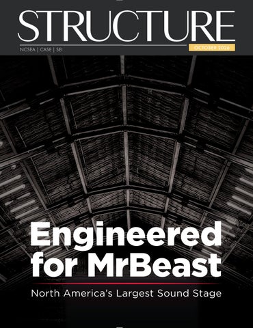
Engineered for MrBeast North America’s Largest Sound Stage
MrBeast’s Sound Stage CONNECTIONS
HSS HUB
™
MrBeast’s Record-breaking Sound Stage. Engineered with HSS from Atlas Tube.
eered rBeast
Join 3,800+ engineers and fabricators using this indispensable and complimentary online resource, now including extended field-welded configurations, a new feature linking bracing calculators to beam calculators and more. No more developing and maintaining custom spreadsheets. Teams can collaborate directly on the HSS Connections Hub, quickly create connection calculations and finalize designs without all the back-and-forth revisions.
In the world of MrBeast, whether it’s presenting world’s tallest dominoes In the MrBeast, whether presenting world’s tallest or the world largestofbowl of cereal ever, it’s superlatives are the name of dominoes the game. or the largest bowl of cereal ever, superlatives are the name of the game. MrBeast’s campus in Greenville, NC, needed a soundstage of superlative MrBeast’s campus in Greenville, NC, needed a soundstage of superlative performance, including a ceiling capable of supporting a hanging car at any performance, including ceiling capable of supporting a hanging car at any location throughout theastructure. location throughout the structure. The engineer, Collins Structural Consulting (CSC), initially considered a more The engineer, Collins Structural Consulting (CSC), initially a more traditional portal frame system using vertical columns andconsidered inclined, momenttraditional portal frame beams. system using vertical columns and inclined, momentconnected wide flange connected wide flange beams.
The world’s biggest YouTuber just inaugurated North America’s biggest sound stage. An exceptional structure made possible by the exceptional structural capabilities of HSS from Atlas Tube.
argest argest Sound Sound Stage Stage
170+ typical details and calculators for HSS connections.
HSS Frame Rib HSS Frame Rib Splice with Shuriken Splice with Shuriken Tension rod Tension rod Gusset with Shuriken Gusset with Shuriken An elevation of one of the frame ribs. The structure acts like a tied arch, with compression tension between the supports. rods An elevation in of the oneframe of theand frame ribs. The structure acts like aTension tied arch, with increase moment resistance caused bybetween the irregular shape andTension unbalanced compression in the frame and tension the supports. rods loading. increase moment resistance caused by the irregular shape and unbalanced loading.
But with a 150-foot clear span, the But with a 150-foot clear very span,heavy the frames would have been frames would been very heavy and would cuthave into the building’s and would cut into the building’s usable space. usable space. “As an alternative, we started “As an alternative, looking at a frame we thatstarted roughly looking at a frame roughly followed the shapethat of the roof,” followed the shape of the said Scott Collins, Principalroof,” atMove CSC.beyond said Scott Collins, Principal atconvention. CSC. Start using “And then we applied load to the the HSS Connections “And then we applied load to the frame and let it bend to whatever Hub today. frame and let it bend whatever shape it wanted. Thento we asked: shape wanted. Then we asked: how doitwe push it back into shape how do we push it back into shape so we can carry the load we need?” so we can carryatlastube.com/hub-start the load we need?”
A frame being erected. The end sections have been set, and the center section is assembled on the ground. The interior space meant all lifting was done with a small crane.
The answer was HSS. 10-inch square HSS, produced in the U.S.A. by Atlas Tube, was used for the frame ribs. “When you’re dealing with long shapes with little bracing, HSS is going to be a lot stronger than wide flanges,” said Collins. By relying on arch action and using HSS for the main members, steel tonnage was reduced from approximately 480 tons to 280 tons, yielding significant cost savings.
The Shuriken® Connection The frames were constructed from multiple short, mitered sections. Welding the connections was a non-starter due to the height of the structure and nature of the angled joints. Instead, the Shuriken® Structural Nut Keeper was used to allow field bolting from the exterior of the HSS, with connections designed in double shear to keep them compact. Splice plates for the vertical walls of the HSS were cut in a chevron shape. Those at the top and bottom were simply bent to match the angle of the joint.
A place for big ideas. Kinked, double shear Shuriken splices after fabrication. The Shuriken were staggered to avoid conflicts within the square HSS members. Inset: Finite element modeling of a kinked connection.
The new sound stage will be the site of untold creativity for years. An incredible feat of creative engineering will always be part of the show, just overhead. Visit atlastube.com/beast to read the case study.
Download the full case study.
HSS HUB CONNECTIONS
™
170+ typical details and calculators for HSS connections. Join 3,800+ engineers and fabricators using this indispensable and complimentary online resource, now including extended field-welded configurations, a new feature linking bracing calculators to beam calculators and more. No more developing and maintaining custom spreadsheets. Teams can collaborate directly on the HSS Connections Hub, quickly create connection calculations and finalize designs without all the back-and-forth revisions.
Move beyond convention. Start using the HSS Connections Hub today.
atlastube.com/hub-start
STRUCTURE OCTOBER 2026
NCSEA | CASE | SEI
Protecting the
Salt Lake Temple for Its
MASONRY & BRIDGES INSIDE: Internal Masonry Wall Bracing Suspension Bridge in Indianapolis Resurrecting a Post Truss Bridge
12 22 34
Future
p. 28
HSS HUB CONNECTIONS
™
The ever-expanding, completely complimentary online resource. Atlas Tube’s HSS Connections Hub streamlines workflows, saves time and helps teams move beyond convention to leverage the full potential of HSS.
WWW.STRUCTUREMAG.ORG
FIND IT ALL IN STRUCTURE RESOURCES FOR THE PRACTICING ENGINEER
Article Archives Each new issue of STRUCTURE and its articles are posted to the website, dating back to 2012
Ask Archie, Our New SE GPT Check out our updated AIpowered tool educated on the NCSEA ecosystem, including STRUCTURE’s archives.
Free Webinars Watch a collection of free presentations from STRUCTURE and its partners.
Structural Engineering Resource Guide Find your next industry partner for anchors, foundations, concrete, software, wood products, steel, connections and more.
PLUS READ THE LATEST SE NEWS www.structuremag.org
ADVERTISER index
Please support these advertisers
Adhesives Technology Corp. ................................................64 Allen Business Advisors.............................................. 63 Anthony Forest/Canfor.................................................9 ASC Steel Deck........................................................... 78 Atlas Tube....................... Front Cover Gatefold, 77 Canadian Wood Council .......................................................81 Chicago Clamp ............................................................ 10 CSI -Computers & Structures, Inc. .............Back Cover CTS Cement ............................................................... 66 ENERCALC ............................................................. 7, 73 IDEA StatiCa.................................................................17 IES.......................................................................................3 INDUCTA............................................................................................67
LeJeune Bolt ......................................................................................70 MAPEI....................................69, Inside Back Cover MAX USA Corp .............................................................................62 NCEES........................................................................... 65 New Millennium.......................................................... 79 PS=Ø.............................................................................. 68 Quikspray...................................................................... 72 RISA ............................................................................... 75 SBCA....................................................................................................82 Simpson Strong-Tie .................................................... 71 Strongwell, Inc..................................................... 21, 80 Tstrata.....................................................................................................20
Statement of Ownership, Management, and Circulation (All Periodicals Publications Except Requester Publications)
STRUCTURE
®
CIRCULATION
subscriptions@structuremag.org
EDITORIAL BOARD Chair John A. Dal Pino, S.E. Claremont Engineers Inc., Oakland, CA chair@STRUCTUREmag.org Kevin Adamson, PE Structural Focus, Gardena, CA Marshall Carman, PE, SE Schaefer, Cincinnati, Ohio Erin Conaway, PE AISC, Phoenix, AZ Sarah Evans, PE Walter P Moore, Houston, TX Steven Judd Interstate Brick, West Jordan, Utah, and H.C. Muddox, Sacramento, California
Publication Title: STRUCTURE; 2) Publication Number: 1536-4283; 3) Filing Date: 9/23/26; 4) Issue Frequency: Monthly; 5) Number of issues Published Annually: 12; 6) Annual Subscription Price: $75-Domestic; $90-Canada; $135-International; 7) Complete Mailing Address of Known Office of Publication: 20 N. Wacker Drive, Suite 750, Chicago, IL 60606; Contact Person: Alfred Spada; Telephone: +1 (312) 649-4600; 8) Complete Mailing Address of Headquarters or General Business Office of Publisher (Not printer): 20 N. Wacker Drive, Suite 750, Chicago, IL 60606; 9) Full Names and Complete Mailing Addresses of: Publisher – Alfred Spada, 20 N. Wacker Drive, Suite 750, Chicago, IL 60606, Editor – Alfred Spada, 20 N. Wacker Drive, Suite 750, Chicago, IL 60606, and Managing Editor – Shannon Wetzel, 20 N. Wacker Drive, Suite 750, Chicago, IL 60606; 10) Owner: NCSEA Media, Inc., 20 N. Wacker Drive, Suite 750, Chicago, IL 60606; No individual owners; 11) Known Bondholders, Mortgagees, and Other Security Holders Owning or Holding I Percent or More of Total Amount of Bonds, Mortgages, or Other Securities: None; 12) Tax Status, N/A; 13) Publication Title: STRUCTURE magazine; 14) Issue Date for Circulation Data Below: September 2026; 15)Extent and Nature of Circulation. (Average No. Copies Each Issue During Preceding 12 Months, No. Copies of Single Issue Published Nearest to Filing Date); 15a) Total Number of Copies (Net press run): 27,416, 27,959; 15b) Paid Circulation (By mail and outside the mail) 1. Mailed Outside County Paid Subscriptions Stated on PS Form 3541: 24,640, 25,084; 2) Mailed In-County Paid Subscriptions Stated on PS Form 3541: 0, 0; 3. Paid Distribution Outside the Mails Including Sales Through Dealers and Carriers, Street Vendors, Counter Sales, and Other Paid or Requested Distribution Outside USPS: 0, 0; 4. Paid Distribution by Other Classes of Mail Through the USPS: 0, 0; 15c) Total Paid Distribution (Sum of 15b (I), (2), (3), and (4)): 24,640, 25,084; 15d) Free of Nominal Rate Distribution (By mail and outside the mail); 1. Free or Nominal Rate Outside-County Copies Included on PS Form 3541: 0, 0; 2. Free or Nominal Rate In-County Copies Included on PS Form 3541: 0, 0; 3. Free or Nominal Rate Copies Mailed at Other Classes Through the USPS: 0, 0; 4. Free or Nominal Rate Distribution Outside the Mail: 17, 0; 15e) Total Free or Nominal Rate Distribution [Sum of 15d (I), (2), (3) and (4)]: 17; 0; 15f) Total Distribution (Sum of 15c and 15e): 24,657, 25,084; 15g) Copies not Distributed: 2,776; 2,875; 15h) Total (Sum of 15f and 15g,) 27,433, 25,906; 15i) Percent Paid(15c divided by 15f times 100): 99%, 100%; 16) Electronic Copy Circulation: None; 17) Publication of Statement of Ownership: Will be printed in the October 2026 Issue of this publication; 18) I certify that the statements made by me are correct and complete: Alfred Spada, Executive Editor.
Linda M. Kaplan, PE Pennoni, Pittsburgh, PA
Publication of any article, image, or advertisement in STRUCTURE® magazine does not constitute endorsement by NCSEA, CASE, SEI, the Publisher, or the Editorial Board. Authors, contributors, and advertisers retain sole responsibility for the content of their submissions. STRUCTURE magazine is not a peer-reviewed publication. Readers are encouraged to do their due diligence through personal research on topics.
aspada@ncsea.com
Jessica Mandrick, PE, SE, LEED AP Gilsanz Murray Steficek, LLP, New York, NY Brian W. Miller Cast Connex Corporation, Davis, CA Evans Mountzouris, PE Retired, Milford, CT Kenneth Ogorzalek, PE, SE KPFF Consulting Engineers, San Francisco, CA (WI) John “Buddy” Showalter, PE International Code Council, Washington, DC Eytan Solomon, PE, LEED AP TYLin, New York, NY
EDITORIAL STAFF Executive Editor Alfred Spada Managing Editor Shannon Wetzel swetzel@structuremag.org
MARKETING & ADVERTISING SALES
ADVERTISEMENT–For Advertiser Information, visit STRUCTUREmag.org
Get 15% off with STR2026 iesweb.com/str
I E S
Senior Director for Business Development & Marketing Monica Shripka Tel: 773-974-6561 monica.shripka@STRUCTUREmag.org
Sales Manager TaVodrick Cottonham Tel: 847-900-9750 TCottonham@ncsea.com STRUCTURE magazine (ISSN 1536 4283) is published monthly by The ®
Proven
structural software for over 30 years
Flexible
licensing to meet your needs
Reliable
support from professional engineers
National Council of Structural Engineers Associations (a nonprofit Association), 20 N. Wacker Drive, Suite 750, Chicago, IL 60606 312.649.4600. Periodical postage paid at Chicago, Il, and at additional mailing offices. STRUCTURE magazine, Volume 33, Number 10, © 2026 by The National Council of Structural Engineers Associations, all rights reserved. Subscription services, back issues and subscription information tel: 312-649-4600, or write to STRUCTURE magazine Circulation, 20 N. Wacker Drive, Suite 750, Chicago, IL 60606.The publication is distributed to members of The National Council of Structural Engineers Associations through a resolution to its bylaws, and to members of CASE and SEI paid by each organization as nominal price subscription for its members as a benefit of their membership. Yearly Subscription in USA $75; $40 For Students; Canada $90; $60 for Canadian Students; Foreign $135, $90 for foreign students. Editorial Office: Send editorial mail to: STRUCTURE magazine, Attn: Editorial, 20 N. Wacker Drive, Suite 750, Chicago, IL 60606. POSTMASTER: Send Address changes to STRUCTURE magazine, 20 N. Wacker Drive, Suite 750, Chicago, IL 60606. STRUCTURE is a registered trademark of the National Council of Structural Engineers Associations (NCSEA). Articles may not be reproduced in whole or in part without the written permission of the publisher.
OCTOBER 2026
3
Contents O C TO B E R 2 0 26
PROTECTING THE SALT LAKE TEMPLE FOR FUTURE GENERATIONS
By Mason Walters, Rene Vignos, Brent Maxfield
Part 1 of this three-part series explores the history, scope, and challenges in seismically isolating the stone masonry structure so it can stand for another century or more.
28
F E A T U R E S REINVENTING THE SUSPENSION BRIDGE FOR AN URBAN CROSSING
RESURRECTING THE LAST COMBINATION POST TRUSS
By Matthias Peltz, PE, and Michael A. Stein, Dipl. Ing., PE
By Daniel Kurdziel, PE
22
Flat steel plate ribbons and fan-like masts on the 16 Tech Bridge bring a first-of-
The 1869 Bell Ford Bridge, the last of its kind, was reconstructed using the
its-kind structure to Indianapolis, linking innovation with community.
original salvaged wrought iron, surviving timber members, and modern structural analysis.
STABILIZATION AND REHABILITATION OF THE STONE BUILDING By Alan Pinciaro, Assoc. AIA, and Andrea Landry, EIT
Vacant since 2004, the 1830s Greek Revival structure in Augusta, Maine, is undergoing restoration work to support future use. 4
34
STRUCTUREmagazine
42
C O L U M N S a n d D E PA RT M E N TS 6 Editorial One Model Code, Fifty Licensure Models
47 Professional Topics
By Andrea Reynolds, PE, SE
By John R. Allen, III
How to Sell Your Engineering Firm
8 Structural Design Modeling and Development of Impact Loads on Marine Structures Due to Vessel Collision By Adrienne Crider
50 InSights
12 Structural Design Internal Masonry Wall Bracing: What EORs Need to Know By Philippe Ledent, PE, SE, Todd Dailey, PE, and Kyle Lochonic
52 Historic Structures
14 Codes & Standards Creating a Road Map for Code Adoption of High-Strength Steel Reinforcing Bars y Dimitrios Kalliontzis, Ph.D. B
60 Codes & Standards
18 Structural Design Navigating the Cracked Masonry Design Requirements for Post‑Installed Anchors y Derek Gilbert B
Structural Decisions and Lifecycle Considerations in Bridge Rehabilitation or Replacement y Prateek Srivastava B
Government (Arsenal) Bridge 1872 By Dr. Frank Griggs, Dist. M. ASCE
FAQ on SEI Standards By Jeannette Torrents, PE, SE
In Every Issue 3 Advertiser Index 54 NCSEA News
56 CASE in Point 58 SEI Update
61 STRUCTURAL ENGINEERING Resource Guide 2026/2027
Special Section
Annual Special Section with resources for structural engineers, including profiles of some of STRUCTURE’s advertisers and categorized product listings. ADVERTISEMENT–For Advertiser Information, visit STRUCTUREmag.org
OCTOBER 2026
5
EDITORIAL One Model Code, Fifty Licensure Models The Case for Consistent SE Licensure By Andrea Reynolds, PE, SE
M
y path to structural engineering licen- on who is qualified to do it from one state to sure began with a nudge. John, my the next. That is not a convenience issue—it former supervisor, encouraged me to pursue determines who can respond after a disaster or the SE in Illinois, back before I knew there was how quickly a firm can put the right engineer anything beyond my PE and before a national on the right project. Closing that gap needs structural exam existed. I took his advice with practicing engineers in the room, engineers no idea that jurisdictions across the country like you, volunteering because they care about recognize structural engineers so differently. the profession’s future. That education came later, when I was direcThere is a public-facing side to this too. tor of structural engineering at an A/E firm Many owners, developers, and architects still serving clients nationally. Practicing across do not know what a structural engineer does. state lines and in responsible charge meant The We SEE campaign has raised awareness, confronting the full patchwork of licensure and I am excited for NCSEA’s upcoming inimodels: some jurisdictions license structural tiatives to communicate the value of structural engineers separately, some tie it to building engineering and of a career in it. Awareness type or occupancy, and some do not distin- is how we attract the next generation; clarity guish at all. That patchwork pulled me into and consistency is how we keep them. serving the profession. Keeping them means fixing how we license Licensure advocacy them. Licensure is about protectstands on three Licensure advocacy is about ing public health, pillars: education, protecting public health, safety, and welfare, experience, and not keeping people examination, and safety, and welfare, not out of the profeswe spend most of keeping people out of the sion, though when our worry on the profession, though when you are in the middle third. The jouryou are in the middle of the of the process it ney begins with process it can certainly feel can certainly feel education (though that way. that way. Through for many of us it the Structural began with Legos Engineering and erector sets, we Licensure Coalition just didn’t realize it (NCSEA, SEI, and CASE) we are pushing yet), a degree leads to a job, and experience to protect licensure, to define it consistently accumulates. The examination is what hangs through model language that states can adopt, overhead, and where the PE Structural exam and to make the credential travel with the marathon is your entry requirement, that engineer who earned it. weight is considerable. For me it was 45 hours I understand the worry this may raise; where of examinations to practice across the counstructural and civil licensure are not distin- try. I imagine a future where the PE Civil/ guished, consistency can sound like additional Structural and PE Structural exams build on requirements, but the goal is agreement on one another, so examination time drops and what the credential means and how to transi- the path is shorter than the one I walked. tion, not a mandate that every engineer take That weight is most visible in the recent additional exams. exam transition. Initial pass rates on the We have precedent for this. Into the 1990s computer-based building depth exams felt we designed under competing model codes shockingly low, though comparable to rates and one-off local amendments; today nearly when the 16-hour national exam was introevery jurisdiction has adopted a single model duced and took three years to normalize. Pass building code, carried there by a common rates jumped when an hour was added this understanding of the underlying engineer- April, which suggests time was a real factor. ing principles and the need to protect public We are working through an adjustment safety. Licensure rests on the same under- period, and if you are caught in it, that may standing: we agree on the engineering, but not not feel reassuring. 6 STRUCTURE magazine
And remember that the exam is not graded on a curve. It tests for the minimum competence needed to protect the public, and determining that threshold honestly is the most consequential thing we do. Advances in technology, new materials, more complex structures, and changing environmental loads have raised the stakes, especially for the significant structures where SE licensure matters most. I know how heavy the licensure path can feel. My hardest step was the Washington SE3, compounded by my firm balking at the exam and travel costs. I let myself consider walking away, then decided an expense report should not limit my career, my firm’s projects, or my group’s experience. I sat for it in October of 2010 and waited four grueling months to see a 22% pass rate with my name on the right side of it. The fight to get there made it sweeter. When I say this path is hard, I mean it, but the pride at the end makes it all worth it. I do not think that path should require an engineer to keep proving the same competence in different formats. John nudged me toward my first SE license before I understood what he was handing me, and I have spent my career trying to return the favor. That is the obligation: to make this path clearer for the engineers behind us. Join me, and many others already at it. The structures we design outlast us. So should the profession we hand down. ■
Andrea Reynolds, PE, SE, is the director of structural engineering at SmithGroup. Her work encompasses multiple markets—sports stadia, military installations, research centers—and also spans the globe. Reynolds has extensive experience with extreme loading scenarios, including hurricane, high seismic, tornado and blast. She also sits on the Structural Engineering Exam Committee and serves on the NCSEA Board of Directors.
structural DESIGN Modeling and Development of Impact Loads on Marine Structures Due to Vessel Collision
Achieving reliable predictions for structural performance during collisions demands advanced techniques such as finite element analysis, strut-and-tie idealizations for force transfer, and specialized computational tools capable of capturing contact behavior, structural nonlinearity, and system-level response. By Adrienne Crider, PE
The Francis Scott Key Bridge collapsed in 2024 following a collision by a large container ship.
T
he collapse of the Francis Scott Key Bridge in Baltimore in March 2024 renewed focus on one of structural engineering’s most demanding challenges: developing and modeling impact loads on marine infrastructure due to vessel collision. While the probability of ship impact has been reduced over time with advances in navigation systems, AIS (automatic identification system) tracking, and vessel traffic management, it has not been eliminated. Marine structures, including bridge piers, dolphins (man-made structures of wood, steel, or concrete installed to protect substructures), offshore platforms, and port facilities, are often located in heavily trafficked waterways. These structures are exposed to vessels that can range from smalls crafts to large container ships exceeding 400 meters in length. While collision events are relatively rare, their consequences can be severe involving progressive structural failure, loss of life, and major economic disruption. Because these low probability events carry high load demand, a highly rigorous, mechanics-based approach to impact load development and structural modeling may be necessary. Unlike standard loads such as gravity loads, vessel impact is fundamentally an energy dissipation problem. It is highly transient, nonlinear, and event driven by force interaction between deformable bodies. The impact load emerges from the dynamic exchange of energy and momentum between the vessel, structure, and foundation system and 8 STRUCTURE magazine
the stiffness of the structure and the vessel. Vessel collision should therefore be treated as an energy dissipation problem rather than a static force application. The total kinetic energy during the collision event depends on the displacement mass of the vessel, the additional mass due to hydrodynamic effects, and the impact velocity. The additional mass from hydrodynamic effects accounts for the immense volume of water traveling with the ship around the hull, which significantly amplifies the total effective mass of the vessel. During impact, kinetic energy of the vessel is dissipated and absorbed simultaneously through several distinct mechanisms. A large portion of the energy is absorbed by the deformation of the structure and the vessel bow crushing. The vessel bow undergoes progressive plastic crushing through the sequential collapse of its hull and internal framing. The stationary structure absorbs energy through localized deformation and damage and, in severe events, global lateral displacement. A fraction of the energy is absorbed by the lateral compression of the surrounding soil, rearrangement of soil particle grains under lateral demand, and compaction of soil beneath the foundation units as axial loads redistribute during impact. Partial uplift of the vessel hull against the water surface further dissipates a portion of the collision energy. Because it is difficult to quantify every dissipation mechanism accurately, models should be simplified by purposefully neglecting non-governing mechanisms.
MORE PRODUCT SOLUTIONS FOR THE MASS TIMBER MARKET
TOMORROW’S ENGINEERED WOOD - TODAY! • Cutting-Edge Equipment: New 52” technologically advanced glulam press and lay-up system. • Versatile Production: Widths produced range from 2-7/16” to 10-1/2”, while depths range from 3-1/2” to 35-3/4”. • Expanded Size Options: Finished Glulam Sizes up to 10 ½” x 35 ¾” x 60’. • Diverse Applications: Available in various appearance classifications and strength grades for Commercial, Industrial, and Residential applications. • Superior Quality: Manufactured with superior strength southern yellow pine MSR Lumber. • Sustainability: Sustainable Forestry Initiative (SFI®) is certified for environmentally conscious projects. CA N FO R . CO M
|
800.221.BEAM
|
A N T H O N Y FO R E S T. C O M
Anthony Forest Products is part of the Canfor Group of Companies Anthony Forest Products Company, LLC
©
Impact Analysis
frequency of collapse is compared to an acceptance criterion. The AASHTO LRFD Bridge Design Specifications (10th edition, 2024) and To perform an impact analysis, one or more design vessels must be the AASHTO Guide Specifications for Vessel Collision Design of Highway determined and agreed upon by all stakeholders, including the owner Bridges (2010) provide three frameworks—Method I (Deterministic of the structure and governing agencies. The magnitude and character Analysis), Method II (Probabilistic Analysis), and Method III (Risk of the impact load are directly governed by the design vessel. Impact Based, Economic Analysis) for vessel selection based on waterway energy scales linearly with mass and the square of velocity, meaning a traffic composition and acceptable risk thresholds. smaller, faster powered vessel may produce a more demanding load than Per AASHTO Method II analysis, the acceptable Annual Frequency a larger, slowly drifting one. of Collapse (AF) is <0.0001 for Critical/Essential Bridges and <0.001 If the protection is sized for largest possible impact, it might result in for Typical Bridges (The operational importance classification should a massive and cost-prohibited protection system, especially for water- be decided by the bridge’s owner). The AF is estimated as: ways used by large vessels. Therefore, the design vessel is selected using AF = (N) (PA) (PG) (PC) (PF) a probability-based analysis procedure in which the predicted annual Where: N = Annual Number of Vessels PA = Probability of Vessel Aberrancy ADVERTISEMENT–For Advertiser Information, visit STRUCTUREmag.org PG = Geometric Probability PC = Probability of Collapse PF = Protection Factor This framework directly informs the severity of the impact load to be developed, linking structural demand to pre-determined quantified risk rather than arbitrary worst-case assumptions. Joist Grip Framing Clamp System Past research has attempted to translate Support your rooftop loads in uplift and complex collision scenarios into quantified download conditions. The distributed load impact loads that can be used for design. capacity of 4,000 lbs per complete system Minorsky (Minorsky, V.U.: “An Analysis of makes the Joist Grip Framing Clamp System Ship Collision with Reference to Protection the ideal support for rooftop unit installations. of Nuclear Power Plants,” Journal of Ship Research, Vol. 3, 1959) relates the volume of structural material destroyed to absorbed Pipe Header System kinetic energy, establishing the foundational energy-based framework for impact assessHanger Clamps, rated for 1,000 lbs each allow hanging of equipment below the roof ment. Pedersen and Zhang (Pedersen, P.T.; deck while utilizing the ability of the Framing Zhang, S. “On Impact Mechanics in Ship Clamps to distribute the load to panel points Collisions,” Mar. Struct. 1998, 11, 429–449.) on the top chord of the bar joist. advanced this by accounting for bow geometry, deformation mechanics, and energy partitioning between vessel and structure—a Suspension Clamp System more physically complete model validated Panel Point Bridge against documented collision events. The AASHTO LRFD Bridge Design Utilize the Panel Point Bridge to safely suspend HVAC equipment, conveyors or Specifications (10th edition, 2024) provides other ceiling fixtures without welding or an equivalent static force as a function of vessel drilling using the Suspension Clamp System. deadweight tonnage and impact velocity. (A3.14.8) Force resulting from a barge collision is also included in the Specification. Additional factors including structural type and shape of Upper Deck Fall Protection System the ship’s bow, amount of ballast carried in the Using corrugations in the standard roof bow, size and velocity of the ship, geometry deck, the Upper Deck Fall Protection of the collision, and geometry and strength Anchorage System easily clamps to the top characteristics of the pier or protection system, chord of the bar joist or wide flange support. are assumed and not included as variables in these equations. While practical for preliminary design, it simplifies a complex dynamic Scan me event into a single static value, failing to capture to find out how Chicago Clamp Co can make your job easier! time-dependent load development, structural flexibility effects, or impulse characteristics governing dynamic response. AASHTO LRFD Plan your next project using Chicago Clamp Systems™ allows for a more rigorous analysis procedure to 708.343.8311 be used in lieu of the static analysis procedure.
When Good Labor is Short, Why Not Make the Job Easier?
©
10 STRUCTURE magazine
Force-Deformation Relationship of the Ship Bow A detailed model requires defining the ship bow force–deformation relationship. As the ship strikes the structure, its bow acts as a crumple zone. As the bow contacts and crushes against the structure, resistance builds progressively, reflecting the sequential collapse of bow framing. This nonlinear curve, when integrated with deformation, equals the energy absorbed by the vessel—directly linking load development to energy balance and serving as the primary input for dynamic structural analysis. Exact specifications and details of the design vessel are required to perform this modeling effort. Any information about the design vessel, if it is even available, would only represent the specific design vessel at the time of modeling. Other vessels using the channel would perform differently. Additionally, any changes in vessel traffic during the life of the structure would not be accounted for. Probable vessel traffic changes should be accounted for during the design of any protection structure. The impact load must be expressed as a force–time history for dynamic analysis. This is derived by coupling the nonlinear bow force–deformation relationship with the vessel equation of motion, producing a time-varying contact force that rises rapidly to a peak and decays as the vessel decelerates. The shape of this profile is governed by the relative stiffness of the bow and the impacted structure. Peak force depends critically on system stiffness. Stiffer structures generate higher peak forces over shorter contact durations, while flexible systems extend contact duration and reduce peak demand. This relationship has direct implications for both load development and structural design. The impulse of the force–time history must equal the change in vessel momentum. This momentum balance is a fundamental mechanical constraint and an essential validation check. Force histories violating this condition are physically inconsistent and must be rejected regardless of how they were derived. The geometry of the bow as it contacts the structure governs the spatial load distribution. Sharp bows form concentrate loads over small contact areas, producing intense local stresses, while blunt geometries distribute pressure more broadly. Adequate mesh refinement at the contact interface is therefore essential in finite element models, as coarse discretization misrepresents pressure localization and distorts both peak force magnitude and distribution. Similar to other conditions, this requires detailed information of the design vessel.
Modeling Vessel Collisions In the case of Vessel Collision analysis, software that specializes in soilstructure interaction can be instrumental in determining the reaction of the structure. A soil specific software, such as FB-MultiPier (Bridge Software Institute), provides detailed nonlinear characterization of the pile foundation system. This governs both the transmission of impact loads into the ground and the energy dissipated through soil–structure interaction. By calculating p–y curves to represent lateral soil resistance along pile depth, the full range of foundation behavior can be captured, incorporating soil grain disturbance, lateral compression around pile shafts, and compaction beneath pile tips. The resulting lateral stiffness characteristics and nonlinear response
Fig. 1 (above). Finite element model input for fender system. Fig. 2 (left). Output of finite element model of fender system. Note the soil springs used for pile dupport.
curves are transferred into a structural modeling software, such as LUSAS Infrastructure design software (finite element analysis). The structural software is used to appropriately represent the complex structural response. The p-y curves are included in the structural software to ensure that the foundation flexibility and soil energy absorption are physically consistent with the global structural analysis. The structural model provides an advanced finite element environment in which derived force–time histories are applied through transient dynamic analysis, capturing inertial effects, dynamic amplification, and structural wave propagation that static methods cannot represent. Material nonlinearity, geometric nonlinearity, and soil–structure interaction are all accommodated. Fender systems are represented as nonlinear springs within LUSAS, capturing their progressive force–deformation behavior and energy absorption directly within the structural model. For a vessel collision model to most accurately represent the actual conditions, the balance of energy must be satisfied. The vessel’s initial kinetic energy should account for all possible dissipation mechanisms—bow crushing, structural deformation, soil grain disturbance, pile tip compaction, vessel hull uplift, etc. Models that inadequately represent any of these pathways risk misallocating energy, either inflating or underestimating the peak structural forces transmitted to the structure. However, accounting for all possible mechanisms is seldom possible, and conservative assumptions should be made to account for any uncertainty. Any results should be cross-checked against momentum balance and energy partitioning to produce physically credible impact load predictions for marine structure design. In the design environment, not all information can be known with enough accuracy to create a detailed model. One example of this includes the use of a design vessel that conservatively represents the vessel traffic. As this is not intended to be an actual vessel, a detailed vessel model cannot be created. In these cases, conservative and accepted assumptions should be made, such as the equations for length of bow damage ncluded in the AASHTO LRFD Specification, for the design of the marine structure. ■ Adrienne Crider, PE, is a senior project manager with Modjeski and Masters, Inc. with more than 20 years of experience in the design, rehabilitation, and analysis of movable and fixed bridges. She has led and contributed to the structural design, analysis, and rating of numerous bridge projects across the U.S.
OCTOBER 2026
11
structural DESIGN Internal Masonry Wall Bracing: What EORs Need to Know
Simple design decisions can increase site safety and decrease construction cost relative to bracing masonry walls during construction. By Philippe Ledent, PE, SE, Todd Dailey, PE, and Kyle Lochonic
“M
eans and methods” can be one of the most divisive phrases in our industry. On most projects, architects and engineers are responsible for specifying the destination while the contractor is responsible for navigating a way to get there. In terms of masonry construction, means and methods can involve the contractor engaging a structural engineer for various responsibilities including masonry wall bracing. The most successful projects often involve a level of cooperation between design and construction teams. Federal Occupational Safety and Health Administration (OSHA) requirements pertaining to the construction industry are typically covered under Title 29 of the Code of Federal Regulations (CFR). Specific to masonry wall bracing during construction, 29 CFR 1926.706 (a) requires that a limited access zone is established whenever a masonry wall is being constructed. Additionally, 1926.706(b) requires that all masonry walls over 8 feet in height are adequately braced to prevent overturning and collapse, and that the bracing system remains in place until permanent lateral support or bracing elements of the structure are in place. Similarly, Article 3.3 E of the Specification for Masonry Structures (TMS 602) requires that the mason contractor “design, provide, and install bracing that will assure stability of masonry during construction.” These requirements can at times be too unrealistic and vague and don’t adequately recognize masonry wall behavior. Design Loads on Structures During Construction (ASCE/SEI 37) provides additional guidance and references other documents, including the Standard Practice for Bracing Masonry Walls Under Construction (Standard Practice) (MCAA 2012) which is widely used to provide an acceptable level of life safety on masonry projects. The Standard Practice defines Initial and Intermediate periods of construction and requires bracing to remain in place until structural elements provide final lateral support or bracing. The Standard Practice also allows for both external and internal bracing. With an internal bracing approach, the early age strength of the masonry (with appropriate strength reduction factors) is used to resist wind loads. Usually internal reinforced behavior is utilized, but internal unreinforced behavior is also an option and can be effective especially for horizontally spanning masonry where flexural stress is parallel to bed joints (such as stair and elevator shafts, or walls with large slenderness ratios—tall height compared to short width). From a design standpoint, the Standard Practice requires that the bracing system be designed to resist a 40-mph construction level wind speed which results in a pressure of 4.1 psf (0.20 kPa). While this wind speed is less than the design wind speed specified in ASCE/SEI 37, which uses reduction factors based on the construction period, many years of successful performance have shown that the 40-mph wind speed is adequate. Often, the reinforcement provided for the final design condition is adequate for internal bracing, as well, though occasionally a contractor may propose adding additional vertical reinforcement to meet internal bracing requirements. 12 STRUCTURE magazine
One of the challenges with internal bracing is developing the reinforcement at the base of the wall so it can function as a vertical cantilever during construction. Proposed language has been added to the 2028 edition of the Building Code Requirements for Masonry Structures (TMS 402) that will require minimum connections between masonry members and supporting foundations, similar to requirements for reinforced concrete members. This reinforcement provides a degree of structural integrity during both the construction stage and life of the structure, and it is common practice to provide fully developed dowels matching the vertical wall reinforcement. Proposed commentary language to this section notes that the presence of this reinforcement does not necessitate considering foundation restraint, and that the foundation may conservatively be approximated as a pinned support for the design of the wall. Research by Pettit and Noguez (2021) has shown the beneficial effects of considering the rotational restraint provided by foundations in the design of out-ofplane walls, though it is challenging to achieve much restraint because the amount of rotation associated with pinned behavior is small. For these reasons, it is recommended to specify fully developed dowels that match the size and spacing of vertical wall reinforcement. In terms of reinforcement lap splice lengths, it is critical for internal bracing that the dowels are fully developed. However, the Standard Practice and the 2016 TMS 402 provide different equations for calculating the required lap length. During the Intermediate period, Section 5.3.3.2 of the Standard Practice requires the following minimum lap splice length: With the allowable reinforcement stress (F’s) of 24,000 psi (based on 60 ksi reinforcing) presented in the Standard Practice, this equation reduces to 48db. However, 2016 TMS 402 Equation 6-1 will typically result in development (and lap) lengths less than that for moderate sized reinforcement.
For example, with centered reinforcement in an 8-inch masonry wall, the lap splice lengths are calculated in Table 1 assuming f ’m is equal to 2,000 psi and 4,000 psi. Table 1. Lap Splice Lengths Bar Size
Standard Practice
f’m=2,000 psi
TMS 402 f’m=4,000 psi
#4
24
13
12
#5
30
20
14
#6
36
38
27
of being designed as internally braced with the design reinforcement. The cost savings on that project were approximately $75,000. On a smaller, 3,800 sq. ft. (353 square meter) wash bay project, increasing the reinforcement from one #5 vertical bar at 48 inches on center to two #5 vertical bars at 32 inches on center eliminated $22,500 of brace cost and resulted in net savings of $16,500. Since moving to internal bracing about three years ago, Donnie Williams, president of DRP Masonry, estimates a cost savings of over $250,000 (compared to traditional pipe bracing). Kent Bounds, president of Brazos Masonry, has had similar experience and commented that exterior pipe bracing interferes with scaffolding and access, slows work for Fig. 1 (left). Grouting masonry is installed. Fig 2 (right). External bracing shown here can be eliminated other trades, creates safety hazards including with walls designed as internally braced. site congestion, is a high cost to purchase, and is labor extensive to install, move, and remove. Recent research by McGinley and Latham (2024) suggests the current Based on all of this, key recommendations for the Engineer of Record lap splices required in the Standard Practice for internal bracing appear on masonry projects include: to be conservative in its calculated capacities of lap splices contained 1. Incorporate the Standard Practice by reference into contract by grout 24 hours after placement. Additionally, the research indicated documents. that in the wall panels tested with high early strength cement included 2. Provide fully developed reinforcement dowels that match the in the grout, a standard lap splice calculated in accordance with TMS size and spacing of vertical wall reinforcement. In the masonry 402 was adequate 12 hours after grouting. Additional research is wall, the dowels are to be fully embedded in grout per the 2016 required and would include a wider variety of unit size, rebar size, and TMS 402/602 provisions. grout types. Designers are encouraged to specify foundation dowels 3. Consider the restraint at the base of the wall as pinned for the to have a lap splice calculated in accordance with TMS 402, though permanent design of the wall unless the foundation can provide mason contractors using internal bracing may request to increase the restraint, in which case the designer should consider forces splice length. Through evaluating failures in high wind events, the induced in the wall and foundation by displacement of the top authors have not encountered foundation failures, and the failure of the wall. typically occurs at the base of the wall from reinforcement yielding 4. Avoid placing control joints in elevator and stair shafts unless or rupture, or shear breakout. required for building performance. With cost being a major consideration for projects, internal bracing 5. Cooperate with mason contractors if they request to increase can offer significant cost savings while prioritizing site safety. Internal the amount of reinforcement, provided it does not result in a bracing eliminates the need to install (and later remove), purchase or reinforcement area in excess of that permitted by TMS 402 or rent braces and associated components such as deadmen, anchors, does not add considerable seismic weight or interfere with other and mounting plates. Additionally, conflicts with other trades and work or trades. construction activities are reduced, and the system is not removable Internal bracing is a tremendous opportunity to increase site safety and gains reserve strength over time. and lower the cost of masonry projects. By considering the reinforceOn a recent Lake High School project, located in Millbury, OH, ment and grout already in the wall, a safety solution can be provided 150 external braces were eliminated with 97% of the walls capable without incurring additional cost. ■ Philippe Ledent is the executive director of the Masonry Institute of Michigan and owner of Ledent Design Solutions where he has provided support on masonry projects throughout the Midwest. Ledent has taught structural masonry design at two universities and currently serves on the board of directors for The Masonry Society and as the secretary for the TMS 402/602 code. Todd Dailey is the president of Dailey Engineering, Inc. and has over 40 years of experience in structural engineering and building design. Dailey is a registered Professional Engineer in 18 states and has provided wall bracing plans and calculations on thousands of projects throughout his career.
At Lake High School in Ohio, 150 external braces were eliminated. The cost savings was $75,000.
Kyle Lochonic is a second-generation bricklayer and has worked in the construction industry for more than 50 years. He is actively involved in masonry education and has taught classes on subjects such as wall bracing, masonry material properties, tuckpointing and repairing historical masonry, structural masonry inspection, and avoiding the most common masonry problems.
OCTOBER 2026
13
codes & STANDARDS Creating a Road Map for Code Adoption of High-Strength Steel Reinforcing Bars
A research program at the University of Houston translated experiment results into balloted code language for The Masonry Society’s work on proposed code revisions. By Dimitrios Kalliontzis, Ph.D.
T
he shift from Grade 40 to Grade 60 reinforcing steel reshaped masonry construction decades ago. A comparable shift toward Grade 80 (550 MPa) reinforcement has been underway in reinforced concrete, and masonry is positioned to follow. High-strength steel reinforcing bars (HSRBs) carry a higher specified yield strength, which lets designers carry the same force with less steel. The payoff for masonry is direct: fewer and smaller bars, less reinforcement congestion in grouted cells, easier handling and placement of bars by masons, and a smaller embodied-carbon footprint. Reinforced concrete already capitalizes on these benefits. ACI 318 Building Code Requirements for Structural Concrete permits HSRBs across axial, flexural, and shear applications, a position built on decades of testing showing that members reinforced with Grade 80 bars develop strength and deformation capacities comparable to Grade 60 members. Masonry design has lagged for one reason: supporting analytical and experimental data did not exist. As a result, TMS 402/602-22 Building Code Requirements and Specification for Masonry Structures caps reinforcement at Grade 60. Allowable stress design limits the reinforcement stress to 32,000 psi, and strength design limits flexural reinforcement to a specified yield strength of 60,000 psi. Both thresholds exclude higher grades. A research program at the University of Houston set out to close that data gap and give The Masonry Society the evidence needed to act. The program pairs large-scale experiments with high-fidelity finite element modeling and translates the results into specific, balloted code language. The sections that follow trace that road map from first feasibility study to proposed code revision.
Fig. 1. Stress-strain comparison of Grade 60 and Grade 80 deformed bars, illustrating the higher yield strength and shorter yield plateau of Grade 80 steel.
percent. A full building design made the case solid. A single-story, high-bay retail prototype redesigned with Grade 80 bars cut total reinforcement cost by about 25 percent, driven largely by the out-of-plane load-bearing walls, where smaller bars replaced larger ones at the same spacing. The study also flagged the limits of the benefit. Gains concentrate in tension-controlled members designed by the strength method; for compression-controlled members and heavily loaded sections, the steel grade has little effect because masonry crushing governs. The balance point for Grade 80 sits lower than for Grade 60, which constrains how much high-strength steel a section can use effectively. These findings set the agenda for the experimental work: confirm the savings and resolve the provisions that stand in the way.
Building the Case: Feasibility and Material Savings The road map began with a question of economics and constructability: does Grade 80 reinforcement pay off in masonry under current design rules? A 2023 feasibility study answered through design case studies of common masonry members, including lintel beams, pilasters, out-of-plane walls, and shear walls, evaluated under both the allowable stress and strength design procedures of TMS 402 Building Code Requirements for Masonry Structures. For tension-controlled members, substituting Grade 80 for Grade 60 reduced the required area of tension steel by roughly 25 percent, with carbon-footprint reductions reaching 33 14 STRUCTURE magazine
Fig. 2. Rebar cost and reinforcement quantity comparison for a prototype masonry building designed with Grade 60 versus Grade 80 bars.
Deformed and Plain Carbon-Steel Bars for Concrete Reinforcement) bars fell short of the conventional 125-percent-of-yield criterion in TMS 402. Because A615 bars serve regions where seismic demand is unlikely to govern, a relaxed 115-percent criterion proved sufficient and reasonable for them. Second, the required factor appeared to depend on bar size, a dependence that should belong to the bar-size factor rather than the grade factor, exposing known conservatism in the TMS 402 size factor for smaller bars. The size factor, therefore, becomes an item for future code revisions.
Fiber-Reinforced Grout: Closing the Lap Length Gap Fig. 3. Measured versus required lap-splice capacities for Grade 80 A706 and A615 bars in concrete and clay brick masonry. The database combines laboratory and numerical analysis results, showing adequate conservatism throughout the spectrum and potential for lap length reductions in future code revisions.
Development and Lap-Splice Lengths: The First Hurdle The clearest obstacle to Grade 80 adoption is bond. A higher yield strength demands a longer development and lap-splice length to transfer the larger bar force into the surrounding grout. The penalty is not proportional, and it grows with bar size. Twenty-two contact lap-splice tests and parametric finite element analyses in concrete and clay brick masonry quantified the demand for Grade 80 bars, with bar size, splice length, and bar standard as the variables. The tests showed that Grade 80 bars require lap lengths as much as 53 percent greater than Grade 60 bars, with the largest penalties for No. 5 bars and larger. To reproduce this in design, the research introduced a grade factor applied to the existing TMS lap-length formula, set to 1.15 for Grade 80 bars, mirroring the approach ACI 318 already uses for high-strength steel. Two findings sharpened the recommendation. First, the bar standard matters: ASTM A706 (Standard Specification for Deformed and Plain Low-Alloy Steel Bars for Concrete Reinforcement) bars consistently developed the code-required splice stress, while the less tightly controlled ASTM A615 (Standard Specification for
Fig. 4. Effect of fiber-reinforced grout on lap-splice response, showing the 26 percent lap-length reduction (from 1 down to 0.74 factor) and the dosage plateau between 1 and 2 percent fiber content.
In special circumstances, longer splices may erode the constructability advantage of Grade 80 steel. Because bond failure in masonry is governed by splitting of the grout around the bar, adding steel fibers to the grout mix offers a way to bridge those splitting cracks, confine the bar, and shorten the splice. The idea is well established in other cementitious materials but rarely used in masonry grout. A program of lap-splice tests, out-of-plane wall testing, and companion material tests evaluated steel hooked fibers at 1 and 2 percent by volume in the coarse grout of No. 7 Grade 80-reinforced specimens. A dosage of 1 percent fibers allowed a 26 percent reduction in the required lap length while still meeting the code splice-stress criterion. Increasing the dosage from 1 to 2 percent gave no further improvement, a plateau explained by the failure mode: the splice still split longitudinally because the surrounding masonry units and mortar joints carry no fiber reinforcement and continue to govern panel response. To bring this into design, the research proposed a fiber-grout factor that multiplies the lap-length requirement, with a recommended value of 0.74 corresponding to the validated 26-percent reduction for Grade 80 No. 7 bars.
Out-of-Plane Wall Tests: Flexural Behavior Lap-splice panels isolate bond, but walls reveal how Grade 80 reinforcement behaves in flexure. Eleven out-of-plane wall tests, the first such dataset in the literature, used hollow concrete and clay brick units across a range of variables: bar size and standard, partial and full grouting, tension- through compression-controlled responses, and continuous
Fig. 5. Load-deflection responses of two equivalent out-of-plane walls reinforced with Grade 60 and Grade 80 bars, compared with TMS 402 nominal and design strength values.
OCTOBER 2026
15
versus lap-spliced bars. was calibrated without high-strength Walls reinforced with Grade 80 bars data, its accuracy for Grade 80 bars is performed comparably to their Grade unverified. An experimental campaign 60 counterparts. Tension-controlled is currently underway to characterize the walls developed large deflections and use of Grade 80 bars as transverse reingood ductility; compression-controlled forcement in partially and solid grouted walls failed by face shell crushing that walls. Figure 6 shows some highlights progressed into a diagonal strut, as from the campaign. expected when masonry crushing gov- Fig. 6. Ongoing masonry shear wall test with Grade 80 erns. Measured strengths consistently reinforcement performed in the structural laboratory at the exceeded the TMS 402-based design University of Houston. From Test Data to Code strengths in every wall, confirming that Language the existing provisions, extended with the grade factor, deliver adequate conservatism for Grade 80 flexThe value of this evidence lies in what changes in the code. The ural design. lap-splice findings translated directly: in 2025, TMS committee Two practical lessons emerged. Walls with Grade 80 bars deflect ballots approved a revised lap-splice length expression for Grade 80 more at service level loading because fewer bars reduce the cracked bars that adopts a grade factor of 1.15 and recognizes the narrower section stiffness, though all walls remained well within the TMS strength distribution of these bars through a reduced minimum 402 deflection limit. Lap-spliced walls behaved differently from splice-stress requirement for low-seismic applications. The flexural those with continuous bars: the spliced bars engaged more effective data support extending the allowable-stress and strength-design steel area than design assumes at the allowable stress limit state, provisions to Grade 80 bars, with a recommended allowable stress and splitting along the splice could limit ductility. These behaviors of 42,000 psi, a proportional increase from the 32,000-psi value point to splice detailing, not flexural capacity, as the item to watch. for Grade 60. Table 1 summarizes the proposed design parameters that the research supports. In-Plane Wall Tests: Shear Behavior Work remains. The bar-size factor in the lap-length expression carries conservatism that future cycles should refine. The maximum Out-of-plane flexure is only part of the picture. Masonry shear reinforcement ratio for Grade 80 shear walls needs experimental walls resist combined axial and lateral load, and their design hinges validation that is being addressed in the aforementioned experimenon a ductile, flexure-controlled response that avoids brittle diagonal tal campaign. Hooked steel fiber-grout factors are established but cracking. Whether Grade 80 reinforcement supports that behavior not yet adopted by TMS 402, and the service-deflection formulas is the next frontier on the road map, and current provisions raise deserve improvement. Even so, the road map is clear: feasibility specific concerns that the in-plane studies set out to resolve. established the value, lap-splice and flexural testing supplied the Analytical shear-wall studies using the TMS 402 procedures show evidence, fiber-reinforced grout addressed the chief drawback, and the same tension-controlled benefit seen in other members: a mean- the first code changes are now in the standard. Grade 80 reinforceingful gain in moment and axial capacity for Grade 80 over Grade ment gives masonry designers expanded flexibility, material savings, 60 below the balance point. The complication lies in the reinforce- and better constructability, and the path to its full adoption by ment limits. The maximum flexural-tension reinforcement ratio is TMS 402 is well underway. ■ inversely tied to the yield strength, so the cap on Grade 80 steel is This research was supported by the National Concrete Masonry Association (NCMA), markedly lower than for Grade 60, and it tightens further for special the Western States Clay Products Association (WSCPA), and the Brick Industry shear walls where ductility demand is highest. Because that limit Association (BIA). In-kind support was provided by the Texas Masonry Council and
Table 1. Proposed Grade 80 Design Parameters Supported by the Research Program Design parameter
Current TMS 402-22
Supported for Grade 80
Allowable steel stress
32,000 psi (Grade 60)
42,000 psi
Strength design yield 60,000 psi (Grade 60)
80,000 psi
Lap-length grade factor
1.00 (Grade 60)
1.15
Min. splice-stress criterion
125% of yield
115% of yield
Fiber-grout lap factor
Not addressed
0.74
16 STRUCTURE magazine
its professional masons, BarSplice Products Inc., Concrete Reinforcing Steel Institute, Interstate Brick, Best Block Construction Materials, Nucor Harris Rebar, D’Ambra Construction, and Veazey Enterprises. The author acknowledges graduate research assistants Muhammad Waleed Khan, Samvid Parajuli, and Omar Khalid, as well as industry advisor John Hochwalt, PE, SE. This article is dedicated to the memory of John Chrysler, a valued member of the masonry community who dedicated three decades of his professional life to the Masonry Institute of America (MIA).
Full references are included in the online version of the article at STRUCTUREmag.org.
Dimitrios Kalliontzis, Ph.D., is an Assistant Professor in the Department of Civil and Environmental Engineering at the University of Houston, where he directs the Structural Performance and Fluid-Structure Interaction Laboratory (dkallion@central.uh.edu).
POWERFUL STEEL AND CONCRETE DESIGN AT YOUR FINGERTIPS
Save time and money with the world-leading structural design software. Connection design at its best Steel anchorage workflow Supplement your strut and tie analysis Any geometry, any loading, in minutes Intergates with your software
www.ideastatica.com
Try the full version for 14 days for free
structural DESIGN Navigating the Cracked Masonry Design Requirements for Post‑Installed Anchors The testing, acceptance criteria, and design requirements for post-installed mechanical and adhesive anchor systems in cracked masonry substrates are reviewed here. By Derek Gilbert, PE
I
n 2002, the American Concrete Institute (ACI) adopted a design methodology for post-installed anchorage in cracked and uncracked concrete substrates. Presently, The Masonry Society (TMS) design standard does not directly address post-installed anchorage in cracked masonry elements. The applicable ICC Evaluation Service (ICC-ES) acceptance criteria approved in 2021 and 2023 prompt post-installed anchor manufacturers to test and publish strength design data in cracked masonry substrates, especially in high-seismic zones. Differences in qualification and acceptance criteria have led to distinct design methodologies for post-installed anchors in cracked masonry and cracked concrete elements.
Post-Installed Anchors in Concrete Elements Standard of Practice
fractile. The remainder of Chapter 17 includes additional cracked concrete calculation driven provisions throughout. ACI 318-19 Section 17.10.3 requires post-installed anchors in structures assigned to Seismic Design Category (SDC) C, D, E, or F be qualified using specific ACI 355.2 and ACI 355.4 Simulated Seismic (cyclic) testing requirements. Section 17.10.5.4 and corresponding commentary state “assuming the concrete is cracked unless it can be demonstrated that the concrete remains uncracked.” The design professional is responsible for determining whether cracked concrete requirements apply. In lieu of evaluating the potential for cracking at individual anchor locations, the design professional may conservatively design for cracked concrete conditions. For structures assigned to SDC A or B and where cracking is determined to not occur at service load levels, post-installed anchor design may use the uncracked concrete provisions.
The International Building Code (IBC), Chapter 19 Concrete (IBC 2024, 1901.3) and the ACI design standard (ACI 318-19 Building Code Requirements for Structural Concrete) both directly recognize mechanical (expansion, undercut, and screw types) and adhesive post-installed anchor systems for use in concrete substrates. ACI 318-19 stipulates that mechanical and adhesive anchors meet qualification standards ACI 355.2 Qualification of Post-Installed Mechanical Anchors in Concrete and ACI 355.4 Qualification of Post-Installed Adhesive Anchors in Concrete. Independent certification bodies assess anchor testing data per acceptance criteria—AC 193 for mechanical anchors and AC 308 for adhesive anchors. Manufacturers of compliant anchors are issued a product evaluation report by the certification body indicating compliance with the building code (Fig. 1).
Cracked Concrete Post-Installed Anchor Design Within ACI 318-19 Chapter 17 Anchoring to Concrete, 17.5 – Design Strength, Section 17.5.1.2 includes two statements. The first calls for theoretical equation-based results be confirmed via testing with “Nominal strength for an anchor or anchor groups shall be based on design models that result in predictions of strength in substantial agreement with results of comprehensive tests.” It introduces the cracked concrete requirement with “For nominal strengths related to concrete strength … influence of cracking shall be taken into account.” The direct ACI 318-19, Chapter 17 calculation-driven influence on cracked concrete anchor capacity first appears in the basic concrete breakout strength of a single anchor in tension equation (17.6.2.2.1). The coefficient for basic concrete breakout strength in tension (kc) is applied to account for cracked concrete. For cast-in anchors (kc) is 24 while (kc) is 17 for post-installed anchors. The corresponding Commentary section indicates (kc) is derived from a large database of test results in uncracked concrete at the 5 percent 18 STRUCTURE magazine
Fig. 1. Standard of Practice for Post-Installed Anchors in Cracked and Uncracked Concrete Elements.
ICC Evaluation Service (ICC-ES) and the International Association of Plumbing and Mechanical Officials (IAPMO) Uniform Evaluation Services (UES), use acceptance criteria to verify product compliance before issuing evaluation reports. Development of new acceptance criteria begins with an application submitted to ICC-ES technical staff. ICC-ES then works with the applicants and interested parties to prepare the criteria for review by the ICC-ES Evaluation Committee. Composed of building officials, the committee uses a transparent, formal process that includes public comment and testimony at a hearing before final approval. The applicable acceptance criteria for mechanical and adhesive anchors in cracked and uncracked masonry are AC01 (24) 2nd Edition and AC58 (24) 2nd Edition, respectively. Both include anchor strength design provisions for solid or hollow clay brick units, grouted, partially grouted, and ungrouted hollow concrete masonry unit construction in cracked and uncracked conditions. As stated in the documents, the anchor strength design provisions in AC01 and AC58 are “derived substantially” from the concrete post-installed anchor provisions of ACI 318-19 Chapter 17, with masonry-specific deletions, modifications, and additions.
Cracked Masonry Post-Installed Anchor Design
Fig. 2. Standard of Practice for Post-Installed Anchors in Cracked and Uncracked Masonry Elements
Post-Installed Anchors in Masonry Elements—Standard of Practice For anchoring into masonry construction, both the building code masonry chapter (IBC 2024—Chapter 21, Sections 2107 and 2108) and referenced masonry design standard (TMS 402-22 Building Code Requirements and Specification for Masonry Structures) do not contain calculation driven post-installed adhesive and mechanical anchor requirements. TMS 402-22 Chapter 8 Allowable Stress Design of Masonry, Section 8.1.4.2 and Chapter 9 Strength Design of Masonry, Section 9.1.6.2 apply to anchors “embedded in grout.” Both chapters require testing to determine the allowable loads or nominal strengths. Commentary 9.1.6 recognizes the range of post-installed anchor “configurations” and directs designers to the manufacturer’s published literature for design guidance. Commentary 9.1.6.2 notes that Section 9.1.6.3 Nominal Strengths Determined by Calculation for Headed and Bent-Bar Anchor Bolts does not address post-installed anchorage. Section 9.1.6.2 refers to ASTM C1892 Standard Test Methods for Strength of Anchors in Masonry which requires a minimum of five masonry failure mode tests (or three tests when only steel failure occurs). Final design strengths are then determined by using 65% of the average failure load and an associated phi (Φ) factor for the corresponding failure mode (Fig.2).
Building Code Approval Path for PostInstalled Anchors in Masonry Substrates Post-installed anchor manufacturers often provide for building code compliance through product evaluation reports, as specified in IBC 2024 Section 104.2.3.6.1 under the alternative materials provisions of Section 104.2.3. Certification bodies accredited to ISO 17065, including
TMS 402-22 does not require a cracked state or a system overstrength factor for cast-in-place or post-installed masonry anchorage. It does not distinguish between cracked and uncracked masonry states for nominal anchor strength determination testing and calculation methods. In 2019, the masonry industry considered the impact a crack has on overall post-installed anchor performance. A major revision to AC58 passed the ICC-ES Evaluation Committee adding cracked masonry testing protocols to adhesive anchors. In 2021, AC01 incorporated similar provisions for mechanical anchors (torque and displacement-controlled, undercut, and screw types) in cracked masonry elements. Compliance dates for the new acceptance criteria were April 15, 2023, for AC58 and August 15, 2026, for AC01. It should be noted that TMS 402-22 does not reference the current AC58 and AC01 criteria, or previous versions of these documents, within its provisions or commentary. In the revised (2nd Edition) version of AC58, the calculation-driven influence of cracked masonry on post-installed adhesive anchor capacity first appears in the basic masonry breakout strength of a single anchor in tension (Nb,m) with modified equation (17.6.2.2.1) from ACI 31819. The effectiveness factor for breakout in masonry (km=12) which includes a reduction factor (αmasonry = 0.70) applied to the concrete breakout effectiveness factor (kc = 17) for post-installed anchors. A viable path for post-installed anchor manufacturers to certify building code compliance via a product evaluation report now includes mechanical and adhesive anchor testing per the updated AC58 and AC01 documents which incorporate cracked masonry strength design requirements. As with the cracked concrete provisions, AC58 and AC01 call for post-installed anchors in masonry to be designed for cracked conditions when the structure is assigned to SDC C, D, E, or F, or when structural analysis indicates cracking may occur under service load conditions, including the effects of wind and seismic demands at the anchor location. The design professional is responsible for determining whether either of these conditions apply to the project or specific anchorage application. In lieu of performing an analysis to assess the potential for cracking under service load conditions, the design professional may conservatively assume a cracked masonry condition. Uncracked masonry may also be assumed when justified by analysis. OCTOBER 2026
19
Masonry Anchor Design Paradigms: ASD & LRFD TMS 402-22 permits both Allowable Stress Design (ASD) and Strength Design (LRFD) methodologies for the design of masonry structures and elements. The design professional has four post-installed masonry anchor design options that align with, or are alternatives to, TMS 402-22. The first of these design options aligns with TMS 402 Chapter 8 ASD methodology and references the allowable tension and shear load values published by the anchor manufacturer based on ASTM C1892 uncracked masonry tests, with an applied factor of safety of five. The recent June 2026 adoption of ICC-ES AC585 Acceptance Criteria for Mechanical Anchors in Uncracked Masonry Construction now continues to allow manufacturers to include uncracked masonry ASD design data for their mechanical anchors that aligns with TMS 402 and IBC, as well as the legacy version of AC01. The second design option, which utilizes an alternate ASD methodology, takes the cracked or uncracked LRFD published load values provided in the anchor manufacturer’s evaluation report and divides them by a conversion factor (α) to obtain ASD load values. The conversion factor is a weighted average of the load factors for the controlling load combination. For example, in a wind load only condition the conversion factor is 1.67 [= 1/0.60]. The third design option follows TMS 402 Chapter 9 LRFD methodology and calculates design strengths using 65% of the average ASTM C1892 test failure loads and the appropriate failure mode based (Φ factor. The fourth design option, which utilizes an alternate LRFD methodology, relies on the anchor manufacturer’s published evaluation report data, compliant with the revised AC01 or AC58 criteria, to determine design strengths for both cracked and uncracked masonry. Today, many anchor manufacturers’ evaluation reports provide strength design values based on acceptance criteria in cracked and uncracked
masonry construction. The design professional looking to leverage the ASD methodology has two options: (1) convert the cracked or uncracked masonry strength design values to ASD using the conversion factor (α); or (2) locate, if available, the anchor manufacturer’s published uncracked masonry ASD data. With the recent adoption of ICC-ES AC585, and the existing TMS 402-22 provisions, some manufacturers have published evaluation reports with uncracked masonry ASD design data for their anchor products.
Post-installed Masonry Anchorage Limitations & Special Inspections When specifying post-installed anchors in masonry, the design professional should review the applicable evaluation report for product-specific limitations and conditions of use. The evaluation report identifies restrictions related to masonry strength, installation orientation, loading conditions, inspection requirements, and required compliance with the manufacturer’s printed installation instructions. The following limitations are common for post-installed masonry anchors: • Tested concrete masonry unit compressive strength is specific to the anchor type. Low-strength masonry ranges between a minimum of 1,500 to 2,000 psi and high-strength masonry, which is limited to fully grouted CMU, is greater than or equal to 5,000 psi. • Tested brick masonry unit compressive strength is determined using ASTM C67 and used for normalization and test result reporting. • Continuous special inspection for horizontally inclined installations and sustained tension loads is required for adhesive anchor systems. • Overhead adhesive anchor installations are not permitted.
ADVERTISEMENT–For Advertiser Information, visit STRUCTUREmag.org
INTEGRATED STRENGTHENING SUPPORT
FROM EARLY DESIGN TO PROJECT COMPLETION.
FIELD CONDITIONS
Tstrata brings together engineering insight, constructability, products and specification, and field expertise to simplify the delivery of structural strengthening solutions from concept to completion. STRENGTHENING SYSTEMS
PRODUCTS + SOLUTIONS
DESIGN + DETAILING
DOCUMENTS + SUBMITTALS
INSPECTION + TESTING INSTALLATION SUPPORT
START EARLIER. FINISH STRONGER.
Stronger structures. Smarter delivery.
20 STRUCTURE magazine
Design support | Engineered systems | Constructability | Field support
www.tstrata.com
•
Anchor installations are prohibited in plastic hinge zones under location determine the masonry state (cracked/uncracked). Designers seismic conditions. may follow strength design or allowable stress design methodologies. • Anchor installation is in accordance with the manufacturers printed Anchor design capacities are specified in published product evaluation installation instructions (MPII). Typically, hollow substrates require reports or confirmed via ASTM C1892 testing. Understanding typical roto-hammer drill settings to use rotation only drilling mode in lieu masonry anchorage limitations and special inspection requirements of hammer plus rotation mode. helps ensure correct installation and optimal anchor performance.■ • Anchors are not evaluated for fatigue or shock loading applications due to the absence of an approved acceptance criteria. • Direct structural support of fire-resistance-rated construction is Derek Gilbert, PE, is senior field engineer at Simpson Strong-Tie, bringing prohibited. more than 26 years of expertise in structural engineering and AEC • Anchor installations located in hollow head joints in ungrouted and technology. He supports engineers, architects, and contractors by delivering partially grouted walls, as well as fully-grouted walls with closed-ended practical solutions for post-installed anchors, CFS connectors, fasteners, and masonry unit construction, are prohibited. mass timber systems. • Anchor installations are permitted in the head joints of fully grouted walls constructed with open-ended masonry unit construction only. • Screen tubes are required for adhesive anchors installed in clay brick masonry construction. Special Inspection requirements for postinstalled anchors in masonry may vary, but in general the following are common: • Periodic or continuous special inspection shall be performed in accordance with IBC Sections 1704 and 1705, and Table 4 of TMS 602. • Continuous special inspection is required for adhesive anchors installed in horizontally inclined orientations and designed to resist sustained tension loads. • A Special Inspector is required for initial installations of each type and size of anchor to verify: • Anchor types, anchor dimensions. • Masonry type, masonry compressive FRP Lasts where Other strength, masonry thickness. • Adhesive identification and expiration Structural Materials Can’t date. • Roto-hammer drilling method, drill • Corrosion Resistant bit size, and compliance with ANSI • Lightweight B212.15-1994. • EMI & RFI Transparent • Hole dimensions, hole cleaning • High Strength-to-Weight Ratio procedures. • Low Electrical & Thermal Conductivity • Installation outside of hollow head • Maintenance Free joints. • Anchor spacing, edge distances, end distances. • Anchor embedment depth. • Tightening torque. • Adherence to the manufacturer’s Want to learn more about FRP and earn PDH credits? printed installation instructions.
DON’T LET STEEL ERODE YOUR REPUTATION
ADVERTISEMENT–For Advertiser Information, visit STRUCTUREmag.org
We offer free virtual or in-person sessions.
Summary The standard of practice for postinstalled anchor design in both cracked and uncracked masonry construction is different from that of concrete. The Seismic Design Category, service load levels, and other design considerations at the anchor
strongwell.com/structure Proudly Made in the U.S.A. BABAA Compliant The World Leader in Pultrusion and Pultruded Fiberglass Structures & Shapes
276-645-8000 • info@strongwell.com www.strongwell.com
OCTOBER 2026
21
Reinventing the Suspension Bridge for an Urban Crossing
Fig. 1. The 16 Tech Innovation District Bridge spans Fall Creek and connects the district to the Indiana University-Purdue University Indianapolis medical corridor. (Photo courtesy of Hadley Fruits)
22 STRUCTURE magazine
Flat steel plate ribbons and fan-like masts on the 16 Tech Bridge bring a first-of-its-kind structure to Indianapolis, linking innovation with community. By Matthias Peltz, PE, and Michael A. Stein, Dipl. Ing., PE
I
n February 2020, the 16 Tech Community Corporation announced plans for a new gateway bridge over Fall Creek in Indianapolis, that could link the 16 Tech Innovation District to the Indiana University-Purdue University Indianapolis medical corridor and function as a civic landmark. schlaich bergermann partner (sbp), with Practice for Architecture and Urbanism (PAU), Martha Schwartz Partners, Shrewsberry & Associates, and several local partners, was awarded the project and went on to develop a first-of-its-kind structure in the United States: flat steel plate ribbons in place of conventional suspension cables, carried over fan-shaped masts. The bridge opened in April 2025 and received the NCSEA Structural Engineering Excellence Award in the Bridge and Transportation category that same year.
A Bridge for the Community The project brief called for four traffic lanes , but the design team saw a possibility to reduce that to two lanes across the structure. Traffic studies confirmed the two lanes would handle projected
volumes comfortably. The recovered width was reallocated for pedestrians and cyclists to build a structure that had a more significant value for the community. The resulting 65-foot-wide deck consists of two traffic lanes, a dedicated bicycle lane, and pedestrian sidewalks that cantilever 11 feet on each side. On the east side, the sidewalk expands to 18 feet at midspan to create a central gathering space and overlook above the creek. This aligned with what had surfaced through community engagement during the planning phase. Residents wanted a crossing that felt safe for all modes of transportation and gave people a reason to stop and gather. They did not simply want a connection between two sides of the creek, but a destination. This intent was applied to the details of the bridge design. sbp integrated the lighting design as part of the structure from the beginning and embedded LED fixtures within the pedestrian handrails and continuous channels along the steel ribbons. The lights traced the wave form of the bridge at night, further establishing it as an urban landmark after dark. Anti-climb protection on top of the ribbon plates was similarly integrated into the smooth aesthetic of the bridge, providing safety without breaking the visual line of the structure.
Fig. 2. The bridge deck includes a central gathering space where pedestrians can stop and enjoy the Fall Creek view. (Image courtesy of Hadley Fruits)
OCTOBER 2026
23
Fig. 3 (above). 16 Tech Bridge spans 342 feet across Fall Creek, with a 152-feet central span and two 95feet side spans. Four concrete piers support the three-span structure. Fig. 4 (right). The bridge comprises two lanes of vehicle traffic, a bike lane, and two pedestrian sidewalks that cantilever 11 feet on each side.
Structural Principle of the Bridge
24 STRUCTURE magazine
The Plate Ribbon System The defining feature of the 16 Tech Bridge is the replacement of conventional suspension cables with flat steel plates. The ribbon plates follow a wave-like profile along the length of the bridge, giving the structure the slenderness and efficiency of a suspension system while remaining appropriate for an urban crossing of this scale. The bridge spans 342 feet across Fall Creek, with a 152-feet central span flanked by two 95-feet side spans. Four concrete piers, arranged in two pairs, support the three-span structure. At each pier, five rectangular hollow sections, each 24 inches deep by 8 inches wide, form a mast. The sections fan outward and rise approximately 13 feet above the deck, allowing the ribbon to transition smoothly over the support rather than bending sharply. The masts also extend below the deck and connect to the concrete piers at the 100-year flood elevation, carrying the architectural expression of the superstructure into the substructure. The ribbon plate, 20 inches wide and 2 inches thick, support the two longitudinal plate girders through vertical hanger plates. The girders are 42 inches deep and 24 inches wide, with web plate thicknesses varying from 0.75 to 1.75 inches and flange thicknesses from 1.125 to 2.5 inches, according to demand. Transverse cross beams at 9.5 feet intervals span 42 feet between the two girder lines and support the composite concrete deck, which is 8 inches thick, including a sacrificial wearing surface. Traffic and pedestrian loads transfer from the deck into the girders and then into the ribbon plates, which act primarily in tension. The vertical forces are transferred through the fan-shaped masts into the piers and foundations. The horizontal component of the ribbon tension is balanced by compression in the girders, creating a self-anchored structure that limits horizontal reactions at the foundations.
Finding the Form The ribbon profile was designed through a numerical form finding process that minimizes bending moments under dead load, leaving the structure to act predominantly in axial tension and compression. This utilizes cross sections more efficiently than a system governed by bending. Using parametric models in Grasshopper, Rhino, and SOFiSTiK, the design team defined the boundary conditions and load distribution along the span. The deck weight was represented as concentrated vertical loads at each cross beam. Static equilibrium at each hangerto-ribbon connection then determined the ribbon angle, producing a funicular polygonal profile.
Fig. 5. Force equilibrium at ribbon nodes
Analysis and Detailing Highlights Global behavior was evaluated using a 3D finite element model from SOFiSTiK with line and shell elements for the superstructure and substructure, with load combinations following AASHTO LRFD requirements. For more complex connection regions, including the mast-to-girder interface and the ribbon-to-girder transition, refined shell-element submodels were developed to study local stress distributions and confirm the detailing of welds and plate geometries.
Fig. 6. Global behavior was evaluated using local finite element analysis of the connection of the girder to the mast.
Integral Behavior and Foundations The bridge is fully integral, with the girders connected directly into the abutments and piers without bearings or expansion joints. This design simplifies long-term maintenance, but it also shifts thermal expansion and contraction, creep, shrinkage, braking forces, and other longitudinal effects as loads on the substructure. To capture that behavior realistically, the design team modeled the driven piles directly in the finite element model, including lateral springs calibrated from site boring data. The foundation system uses driven H-piles to provide reliable support through the variable sands, gravels, and silty soils typical of the Fall Creek floodplain. The connections between the encased girder ends and the reinforced concrete substructure were checked using strut-and-tie models to confirm that concentrated forces from the superstructure could be transferred safely into the abutments and piers.
Fig. 7. The FEM shown here includes the superstructure, substructure, and foundations (SOFISTIK).
Wind, Fatigue, and Robustness The slender ribbon and hanger plates were assessed for wind-induced effects using AASHTO provisions. The fundamental periods were confirmed below 1 second, outside the range where resonance with wind excitation was a concern. With high tension forces in the ribbon and hanger plates, fatigue and fracture behavior were an important aspect of the detailing. Hanger and ribbon connections were detailed for the governing stress ranges, with particular attention to welded terminations, bolted splice geometry, and plate transitions avoiding sharp corners and stress concentrations. Material toughness requirements supported a fracture-safe design approach appropriate for primary tension elements. Although the ribbons carry significant tension, the continuous longitudinal girders and repeated hanger arrangement provide alternate load paths in the event of a localized connection issue, improving the bridge's ability to redistribute forces.
Fig. 8. Integral girder detail at abutments shows how concentrated forces from the superstructure are transferred to the abutments and piers. OCTOBER 2026
25
Fig. 9. Trial assembly of a ribbon segment confirmed the workshop geometry.
Pedestrian-Induced Vibrations With a natural frequency of 3.55 Hz, the sidewalk system falls into a range where human-induced vibration warrant careful evaluation. Using the HIVOSS Design of Footbridges guidelines, the team evaluated two scenarios: an inauguration crowd with a density of one person per square meter and daily commuter use at 0.2 persons per square meter. A dynamic time history analysis showed a maximum vertical acceleration of 2.1 meters/second squared for the crowd scenario, placing the response in Comfort Class 3. Comfort Class 3 is acceptable for a large public event where some movement is expected. Under daily use, acceleration dropped to 0.4 meters/second squared, corresponding to Comfort Class 1, the highest comfort category. In practical terms, everyday users should experience little noticeable motion, while a dense event crowd may feel movement that remains within acceptable limits.
Fig. 10. Ribbon plates and bolted splice were constructed prior to the installation of the anti-climb protection.
Fabrication and Construction The site sits within the Fall Creek floodplain and ties into an existing levee. Both permanent and temporary works had to respect hydraulic performance and flood protection requirements. The wooded creek corridor also provides urban habitat for bald eagles and other animal species, which made it a priority to limit disturbance. The fabrication and erection strategy was shaped around these conditions.
Shop Fabrication and Shipping To reduce the disruptions to the wooded creek corridor, minimize traffic disruptions, and increase cost efficiency, the steel elements were prefabricated by Cimolai in Italy. The bridge was divided into segments sized to fit standard 40-foot containers, with bolted connections used in most locations to simplify field installation. The girders were split into 10 bolted segments, and the masts and hangers were bolted to the girders at locations that would later be embedded in the concrete deck and hidden from view. The exposed ribbon plate splices at the crest of each wave were field-welded to achieve a seamless appearance, while bolted ribbon-to-girder splices were concealed beneath the anticlimb protection. This allowed the completed bridge to read as a continuous ribbon, with the practical logic of bolted modular construction hidden.
Geometry Control and Trial Assembly Fig. 11. The striking 16 Tech Bridge is lit up at night. (Photo credit Kokosing)
26 STRUCTURE magazine
Achieving the correct final geometry under permanent loads
Fig. 12. (Left) Estimated embodied Carbon [kgCO2e/m2] of 16 Tech Bridge. (Right)The bridge earns an A-rating under the SCORBS benchmark.
was critical to ensure the bridge behaves as designed. Specifically, if the ribbon plates did not engage the girders as intended, the girders would carry more load in bending rather than transferring load into the ribbons axially, undermining the structural logic of the system. To guard against this, the full ribbon plate, girder, and hanger assembly for each of the four waves was first trial-assembled in the fabrication shop. Bolt holes for the splices were drilled during trial assembly after the fit-up and survey confirming the geometry. Camber was applied to the girders to meet target road grades after dead-load deflections. Rather than fabricating curved girder segments, the team introduced camber at the splices, which simplified shop work while achieving the required final geometry with only small deviations from the ideal profile.
Field Erection and Flood Protection Once the segments arrived on site, they were partially pre-assembled on the ground before being lifted into position with crawler cranes. The main span required temporary shoring, with the towers placed outside the main creek channel to avoid disrupting water flow. At the southern approach, where the bridge alignment crosses the levee, the design incorporated a removable flood-log barrier. This detail maintains a continuous line of flood protection that can be deployed in advance of high-water events.
Sustainability Embodied carbon has become an increasingly important metric for evaluating infrastructure performance. For the 16 Tech Bridge, a lifecycle calculation covering modules A1 through A5, from material production through construction, yielded a total embodied carbon of approximately 840 kg CO₂e/m² of functional area, including the superstructure, substructure, and foundations. For context, studies referenced in the SCORBS rating framework indicate that conventional steel bridges often range between 1,000 and 4,000 kg CO₂e/ m², with an average around 2,570 kg CO₂e/m². Internal benchmarking across completed sbp footbridge projects has established a range of 500 to 1,800 kg CO₂e/m², with mid-span bridges such as the 16 Tech Bridge generally falling at the lower end of the range. Even on that basis, the bridge sits below the conventional steel-bridge average. Under the SCORBS framework, which normalizes carbon
intensity by span and deck width, the bridge achieves an A rating. The rating reinforces one of the project's central lessons: architecturally expressive infrastructure and environmental efficiency do not need to be in conflict. The result reflects the material efficiency of the plate ribbon concept. Through careful detailing and fabrication, the bridge provides a more efficient primary structure than a conventional girder bridge of comparable span, while also delivering a slender, expressive appearance. Focus on material efficiency extended to the smaller details as well. The benches in the midspan gathering space were fabricated at the local Machyne Makerspace from timber reclaimed from trees cleared during construction, returning something of the site to the people who helped shape the project.
Conclusion The 16 Tech Bridge represents structural efficiency and architectural expression operating together rather than as competing priorities. By adapting classical suspension principles to the specific demands of an urban crossing, the design replaces conventional cables with flat steel plate ribbons, producing a structure with clear load paths, efficient use of material, and a distinctive identity. The design goals were coherent through the integral detailing, precise fabrication, and low embodied carbon result. The bridge expands access for pedestrians and cyclists while delivering a landmark for the 16 Tech Innovation District and the wider city of Indianapolis. ■
Matthias Peltz, PE, is a Senior Project Manager and Structural Engineer at sbp. He served as Project Manager and lead structural engineer for the 16 Tech Innovation District Bridge. Michael Stein PE, is the managing director of sbp's New York City and Los Angeles offices and a member of the board.
OCTOBER 2026
27
Protecting
the Salt Lake Temple for Future Generations 28 STRUCTURE magazine
Part 1 of this three-part series explores the history, scope, and challenges in seismically isolating the stone masonry structure so it can stand for another century or more. By Mason Walters, Rene Vignos, Brent Maxfield
A
major seismic base isolation and renovation project for the iconic Salt Lake Temple of The Church of Jesus Christ of Latter-day Saints (the Church) in Salt Lake City, Utah, will be completed at the end of 2026. Constructed over a 40-year period beginning in 1853 when Salt Lake City was still a small pioneer outpost, the temple’s stacked granite block construction contributes to both its historic significance and its seismic vulnerability. Because of the temple’s iconic importance, the Church undertook a years-long process of engineering and architectural studies to determine how best to preserve it for future generations. Few historic preservation projects have attempted to seismically isolate a stone masonry structure of this scale while preserving its architectural and historic character. This challenging project required development of new analytical approaches, specialized construction techniques, and innovative load-transfer systems to achieve the owner’s long-term performance objectives. Adding to
the challenges were unforeseen existing conditions, evolving project requirements, and the need to develop entirely new construction means and methods capable of achieving the project’s engineering objectives. Two future articles will discuss the project’s engineering and construction approaches in more detail.
History The history of the construction of the Salt Lake Temple illustrates dedication, vision, faith, starts, stops, ingenuity, change orders, and changing technology. In 1846, the Latter-day Saints were driven from their homes in Nauvoo, Illinois, beginning their westward migration that would eventually bring them to the Salt Lake Valley in 1847. A few days after Church leader Brigham Young arrived with the Pioneer Saints in the barren Salt Lake Valley desert on July 24, 1847, he struck his cane down on a specific plot of ground and declared,
Fig. 1 (left). Temple architect Truman Angell developed drawings for every granite stone above the foundation. Fig. 2 (above). Groundbreaking for the temple occurred on February 14, 1853.
OCTOBER 2026
29
“Here will be the Temple of our God.” This declaration demonstrated the importance of building the temple to the people whose current objective was to plant crops, dig irrigation ditches, and provide shelter to survive the upcoming winter. The construction of a temple was a daunting task, considering that supplies would need to be transported via wagon trains. The Temple has become an iconic symbol of the Church and an example of uniquely American architecture, but it was not designed by a trained and experienced architect. Truman O. Angell, a carpenter by trade, was appointed by Young in 1848 as the church architect. His design for the temple was heavily influenced by the church leader who saw the temple in a vision. Young insisted the temple have three towers or spires on the east end and three on the west end. The towers on the east were to be a little higher than those on the west. The center towers were also to be higher than the adjacent spires. Angell used some architectural pattern books to work out the design details, such as Edward
Fig. 3. By 1873, the granite blocks of the temple were about 3 feet above the ground. (Photo by Charles Roscoe Savage.)
Fig. 4. The original cross section showing wood trusses with tall center spaces and mezzanine floors on either side.
30 STRUCTURE magazine
Shaw’s Rural Architecture (1843). In addition to designing the exterior stone of the temple, Angell also developed stone drawings for every stone above the foundation. Each stone was given a unique identification using numbers and letters (Fig. 1). Three descriptive bills and diagrams were used—one for the architect’s office, one for the quarry, and one for setting the stone. The groundbreaking to begin the excavation for the temple occurred on February 14, 1853 (Fig. 2). Four cornerstones were laid on April 6, 1853—a significant accomplishment given that the excavation was 16 feet below ground level on the east side. A temple of the scale envisioned by Young needed a substantial foundation. Fortunately, the soil below the temple is well-consolidated sand and gravel deposited from the nearby City Creek Canyon, rather than the clay soils so prevalent in the Salt Lake City area. The base width of the tiered sandstone foundation varies from 16 feet (4.9 meters) at the north and south walls and up to 40 feet (12.2 meters) at the east and west tower complexes. The sandstone for the foundations came from City Creek Canyon, 4 ½ miles (7.2 kilometers) east of the temple. It took more than 10 years to finish the construction of the sandstone foundations. The work was interrupted by winters, farming, and the need to completely bury the foundation work in 1858 over fears of an approaching U.S. Army in the Utah War. One of the most time-consuming efforts, however, was the rework that needed to be done to provide a more durable and level base to support the cut granite stones for the walls that would extend above grade level. Several layers of stone needed to be removed, and new “flagging” stones cut to provide a solid level support. Construction of the sandstone foundations continued until 1864, when granite basement wall stones finally began to be placed on top of the flagging stones. The large granite (quartz monzonite) stones for the walls came from Little Cottonwood Canyon about 20 miles (32 km) southeast of the temple. It was a four-day round trip bringing the heavy stone blocks to the temple site on oxen-pulled wagons. By 1873, 20 years after construction began, the granite blocks were only about 3 feet (1 meter) above the surrounding ground (Fig. 3). Once the railroad arrived in Utah in 1869, a rail line was extended to the quarry in Little Cottonwood Canyon in 1872, which greatly accelerated the construction of the temple walls. The original drawings showed two levels of large open floors supported on wooden floor trusses with two rows of interior columns. The
Fig. 5. The towers were in progress by 1889. Originally, the towers were planned to be made of wood, but Church leadership decided to switch to stone towers in 1887. This change in material had significant structural implications that were addressed during the recent renovation project.
Fig. 6. The capstone was laid on April 6, 1892. The temple was dedicated one year later on April 6, 1893—40 years after construction began. (Photo by Carter Johnson)
center portions were tall two-story spaces with mezzanine floors on either side. The stone drawings showed stone notches to support the trusses and the mezzanine floors, and stone walls were constructed with these notches. Early drawings of the temple showed six flat towers, and later versions showed wooden towers. The 40 years of construction afforded plenty of opportunities for change. Examples of change include events in 1887 and 1888 that had significant implications for the temple. At this time, after 34 years of construction, the north and south walls had reached their full height, and the towers matched the height of the walls. The interior floors were still not installed. Church President John Taylor passed away in July 1887, and Church Architect Truman Angell passed away in October 1887. Truman’s son, Truman Angell, Jr. had been a strong proponent of switching to stone towers, but this was resisted by Angell, Sr and President Taylor. Following their deaths, the idea was again presented to the new Church leadership, and the decision was made to switch to stone towers. In 1888, Don Carlos Young assumed Angell’s responsibilities on the temple. He was educated as a civil engineer, having received a degree
Fig. 7. Shown here are the Salt Lake Temple and Temple Square on April 18, 2019, shortly before the beginning of the temple’s extensive renovation and seismic strengthening project. Marked buildings were removed in the current project. (Photo by Steve Griffin, Deseret News)
from Rensselaer Polytechnic Institute in Troy, New York. Young now oversaw the completion of the exterior stone towers and interior of the temple (Fig. 5). Under Young’s leadership, the interior framing changed from wood trusses to using steel girders to support the floor system. This change allowed for longer floor spans, thus requiring the use of only one interior granite bearing wall. This change had some implications for the stone walls because block-outs were already carved into the stone. These voids had to be filled in, and new block-outs created to support the steel girders. In addition, the originally envisioned lower-level open floor was now changed to smaller rooms, some with various floor elevations. Under Young’s direction, the originally planned wood roof trusses were changed to steel trusses. The decision to switch to stone towers had significant structural implications. The stone towers added significant mass, resulting in higher bearing pressure on the stone foundations that were laid about 35 years previously (Fig. 6). During the current renovation project, it was noted that there was uneven settlement of the masonry with the original mortar joints dipping down at the towers. The
greater settlement at the tower is correlated to the increased tower mass and increased soil bearing pressure. The stone towers also added significant complexity for the current base isolation project. Part 3 of this article series will focus on the Temple retrofit including the base isolation system, the load transfer system to get the loads onto the isolators, a vertical post-tensioning system throughout the walls and towers of the Temple, an innovative posttensioned steel framing system inside the spires, and the installation of a new roof diaphragm with connections into all the towers. The temple was completed and dedicated in 1893—40 years after construction began. Beginning in 1962, the temple underwent a major renovation, which included replacement of mechanical systems, plumbing, and fire sprinkler lines. New above ground and below ground additions were added to the north of the temple, including a new structure (called the Sealing Addition), which was constructed against the north face of the temple. The current project removed the four structures noted in Figure 7, and a new Sealing Addition was constructed on the base isolation system of the temple.
Seismic Setting and Design Criteria Salt Lake City sits adjacent to the Wasatch fault, one of the most active normal fault systems in the United States and the principal seismic hazard along Utah’s Wasatch Front. It extends 220 miles (350 kilometers) from southern Idaho to central Utah and is divided into 10 segments. The temple is within 11/4 miles (2 kilometers) of the Salt Lake City segment, capable of an M7.2 earthquake. Paleoseismic investigations indicate an average recurrence interval of approximately 1,300 years for major earthquakes on the Salt Lake City Segment, and the elapsed time since the most recent event exceeds that average interval. This information weighed heavily on setting the design criteria for the temple. Starting in the late 1990s and early 2000s, the Church began to assess the seismic vulnerability of its older temples and other buildings. In 2005, the Church commissioned a seismic evaluation by Degenkolb Engineers and a structural building assessment study by ARW Engineers. These studies identified that significant stone sliding could occur OCTOBER 2026
31
Fig. 8. Shown is a rendering of the new Temple Square with the adjacent block. The scope of the renovation included two blocks of new landscape, street improvements, and improvements to other buildings on the blocks. (Photo © Intellectual Reserve, Inc.)
resulting in potential collapse. The studies developed two possible retrofit approaches. The first approach was to provide life safety to the occupants, but it was very invasive and required significant interior work that would destroy the historical finishes inside the temple. This approach would not protect the building from significant damage following the shaking from a strong earthquake. The second approach recommended using base isolation. This approach would significantly reduce the amount of required strengthening and would protect both the occupants and the historic structure from future earthquakes. The seismic evaluation was peer reviewed by Forell Elsesser Engineers. In the early 2010s, many of the mechanical and electrical systems in the temple and north addition began to need repair and improvements. As the scope of this work evolved, questions about combining this work with seismic improvements began to arise. Starting in 2014, the Church authorized additional base isolation feasibility studies by Forell Elsesser engineers. Final approval to begin construction documents was provided in 2018. The life of the temple is expected to be measured in centuries. Given this exceptionally long lifespan, the seismic design considered the severe shaking associated with a major rupture of the Wasatch fault rather than relying solely on the significantly lower, code-prescribed MCER ground motion. The code probabilistic approach does not fully represent the shaking that could occur if such a rupture were to 32 STRUCTURE magazine
happen near the temple. The project therefore adopted a design ground motion based on the 84th-percentile shaking from a magnitude 7.2 earthquake on the Wasatch fault. Even under this severe level of shaking, which includes unusually intense vertical acceleration input, the temple is expected to experience only minimal damage, helping preserve the historic fabric of the edifice. These demanding performance objectives drove many of the project’s engineering decisions. Although base isolation was selected early as the preferred seismic retrofit strategy, subsequent computer modeling demonstrated that isolation alone would not achieve the desired performance objectives. Detailed dynamic analysis unexpectedly revealed that vertical excitation could induce significant horizontal oscillations and sliding demands within the stone tower system. The tower and wall systems needed to be strengthened to meet the performance objectives. A new structural diaphragm was also needed at the roof level to ensure that the towers, walls, and roof were well anchored together. For more detail, look for Part 3 of this series.
Project Scope A significant piece of the project was the base isolation of the historic temple. The temple now rests on 98 Triple Pendulum isolators from Earthquake Protection Systems, but the process of creating and moving the 190-million-pound
(86 M kg) temple onto the isolators and the new footings, adjacent to both sides of the temple foundation, was long and complicated. Three aspects of the load transfer system resonated with the Church during the planning process. The first was that the temple would permanently rest on its original stone foundation. The second was that the native soil the stones were directly set upon would remain until after the load transfer process. The third was that the temple would never “know” that its foundation had been re-supported during load transfer. The soil beneath the temple’s new load transfer system was only excavated after the load had been moved onto new footings flanking the existing walls and towers. For more detail, look for Part 3 of this series. In addition to addressing the seismic structural concerns, the project included the replacement of aging mechanical, electrical, plumbing, and fire sprinkler systems. Improvements to accessibility and comprehensive enhancements to the temple and surrounding ground were also included. This seven-year construction project encompassed two city blocks with a primary focus on the historic temple. The project included the renovation and seismic upgrade of the Salt Lake Temple and added three below grade levels and two entry pavilions to the north of the temple. The new pavilions provide temple access and additional temple functions and were not base isolated. Two new visitor center buildings were added to the south. The project also included two blocks of new landscape, street improvements, and renovations to other buildings on the blocks (Fig. 8). The excavation for the three below grade levels adjacent to the historic temple required excavating 45 feet (13.7 meters) below the existing historic foundations. To maintain the capacity of the very high bearing pressure on the existing foundation and new footings, extensive shoring was required. Part 2 of this article series will focus on the geotechnical studies and field monitoring of the site as well as the extensive scope of shoring systems required to construct the adjacent buildings while also protecting the temple against settlements and movements. Figure 9 provides a simple overview of the load transfer system. Some of the steps needed to construct the system are listed here. For a discussion of the complexities and unique solutions that were considered to accomplish these steps, look for Part 3 of this series. • Consolidation and post-tensioning of the existing foundation. • Shoring of the soil directly below the existing foundation to allow for excavation inside and outside the temple footprint. • The unique installation of 3.5 feet and
• • • •
• • •
4 feet (1 and 1.2 meter) round horizontal pipes below the existing foundation to function permanently as load transfer beams filled with reinforcing steel, post-tensioning duct, and high strength concrete. New footings, flanking each existing footing, to support the base isolators and the weight of the temple. Flat jacks to accommodate footing settlement during temple load transfer. The construction of large transfer girders above the new footings. Compression rods to counteract eccentric loading and to minimize the compression load on the historic foundation. Post tensioning cables. Soil removal following load transfer. Beams to anchor the vertical post-tensioning cables that extend down through the historic walls and foundation.
For more information about the celebration and to view seven years of project updates, visit www.templesquare.org. ■ This material is neither made, provided, approved, nor endorsed by Intellectual Reserve, Inc. or The Church of Jesus Christ of Latter-day Saints. Any content or opinions expressed, implied, or included in or with the material are solely those of the authors and not those of Intellectual Reserve, Inc. or The Church of Jesus Christ of Latter-day Saints.
Mason Walters, SE, NAE is the Project Principal for Forell Elsesser Engineers. Rene Vignos, SE, is the Project Manager for Forell Elsesser Engineers. Brent Maxfield, SE, is a structural engineer in the Special Projects Department of The Church of Jesus Christ of Latter-day Saints but is not speaking for the Church in an official capacity.
Fig. 9. A section through the load transfer system is shown here. Part 3 of this series will explore the complexities and unique solutions to construct this system. (Image courtesy Forell Elsesser)
Conclusion The Salt Lake Temple project demonstrates how modern seismic engineering can be applied to preserve and strengthen historically significant structures while meeting ambitious performance objectives. Achieving these goals required close collaboration among engineers, architects, contractors, specialty subcontractors, and the owner. Two future articles will examine the engineering solutions developed to meet these challenges. The temple now stands prepared to withstand the major earthquakes expected along the Wasatch fault while preserving its historic character for future generations. The Salt Lake Temple will be open for public tours from April 5, 2027, to October 1, 2027.
Project Team Owner The Church of Jesus Christ of Latter-day Saints Architect FFKR Architects Structural Engineer Forell Elsesser (Historic Temple) ARW (All other structures) Contractor Jacobsen Construction
OCTOBER 2026
33
Resurrecting the Last Combination Post Truss
The 1869 Bell Ford Bridge, the last of its kind, was reconstructed using the original salvaged wrought iron, surviving timber members, and modern structural analysis. By Daniel Kurdziel, PE
34 STRUCTURE magazine
The western span of the Bell Ford Bridge collapsed during a windstorm in 1999, leaving the eastern span standing for several more years. Preservation efforts began to reconstruct the western span and rehabilitate the eastern span.
I
n 2006, the last surviving combination Post truss bridge in the world collapsed into the White River in Jackson County, Indiana, and was assumed lost to time. Nearly 20 years later, engineers reconstructed the 1869 Bell Ford Bridge in Hamilton County, Indiana, using the original salvaged wrought iron, surviving timber members and modern structural analysis to return this lost bridge to service as a pedestrian crossing. The Bell Ford bridge was originally built in Jackson County in 1868-1869 by Robert Pattison of the Ohio & Mississippi Railroad. The structure reflected Simeon Post’s 1863 and 1868 patents for his Post truss. Although Post trusses can still be found today, the “combination” Post truss was unusual. This variant was only built during a brief period when construction of bridges was transitioning from timber bridges to wrought iron bridges. The combination Post truss utilized timber for compression members and wrought iron for tension members. In order for these materials to function together, they had to be assembled using numerous iron castings. Although the castings were complicated and highly specialized, the hybrid use of timber and wrought iron allowed the bridge to achieve remarkable structural efficiency with minimal material. The original structure, like many metal Post trusses, was built without a roof or siding. Instead, “rooflets” were used covering each individual upper chord; however, that was insufficient to protect the structure. In an article from 1876 in Seymour Weekly, “Cover the Bridge,” local individuals demanded the Bell Ford bridge be covered and sided to preserve the structure. Sometime afterward, the bridge was ultimately
covered and sided. This grassroots effort is what likely contributed to the Bell Ford's long-term survival, while other combination Post trusses gradually disappeared. This bridge carried traffic on SR258 over the White River until it was bypassed in 1969, exactly 100 years after opening to traffic. The abandoned bridge remained standing until severe winds caused the western span to collapse in 1999. In order to help preserve the last remaining structure of its type, the structure was added to the National Register of Historic Places in 2005. Alas, in 2006, while a rehabilitation effort was in development, the eastern span collapsed. Following both collapses, pontists—historic bridge enthusiasts— from across the country came together to pull the wreckage from the river and store the bridge wherever space could be found. Several attempts were made to rebuild it but all failed, and so the bridge was left as a ruin indefinitel. In 2018, the Hamilton County Commissioners, led by Mark Heirbrandt, negotiated with Jackson County to secure the remains of the bridge for a one-of-a-kind crossing on the Geist Greenway Trail. Then, with additional funding, the Bell Ford Bridge Reconstruction project was born, with Hamilton County leading as the project owner.
Recovering the Bell Ford Bridge Before structural design could begin, the project needed to define which historic and architectural elements would be reconstructed and which modern elements would be incorporated. Because the bridge
Before preservation efforts could be completed, the eastern span collapsed into the White River in 2006. Despite the extensive damage, much of the original material was recovered and ultimately incorporated into the reconstructed bridge. OCTOBER 2026
35
After nearly two decades, salvaged components of the Bell Ford Bridge were recovered from numerous storage locations. Conditions varied considerably, from carefully stored castings and timber members to twisted and bent wrought-iron members left exposed to the elements. The recovered material was consolidated at the Hamilton County Jail for cataloging and assessment for possible reuse.
was no longer on the National Register, the county had greater flexibility in determining its final appearance. Several non-structural features were selected to acknowledge both the history of the Bell Ford Bridge and the heritage of Indiana’s covered bridges. The portal decoration replicated the long-lost Dolan covered bridge, constructed in 1878. Clear 1/2 inch thick polycarbonate siding was selected to acknowledge the fact that the Bell Ford Bridge was originally not sided while also providing trail users with unobstructed views through the structure. Synthetic cedar shakes for the roof were selected to reflect the aesthetic of traditional covered bridges, while gaining the longevity of modern materials. Once these architectural elements were finalized, the total bridge weight could be determined and structural design could proceed. At the same time, the surviving bridge pieces needed to be located and assessed. Individuals from across the state were contacted to determine where the salvaged bridge elements had been stored. Some of the wrought iron members were stored in what were once fields, but were now forests. The timbers, which were stored at numerous locations, often had limited protection from the outdoor elements. Of the two spans that collapsed, about one and a half spans of material were recovered. Because of the scattered locations, the county decided to temporarily store the recovered material in an unused area of the Hamilton County Jail. As the surviving elements arrived, the varying levels of damage became immediately apparent. Some wrought-iron members remained relatively straight, while others were twisted, bent, or fractured entirely. Of the castings that survived, many arrived intact, but just as many were severely damaged or shattered. 36 STRUCTURE magazine
The first major task was for the design team to organize and catalogue the various elements. More than 150 castings comprised of eight distinct types arrived at the jail, along with more than 450 wrought iron members of 18 different configurations and over 100 primary timber elements with hundreds of secondary elements. Once all the pieces were sorted and assessed, enough material remained to reconstruct one entire span. Although about 90% of the original wrought iron could be repaired and reused, much of the original timber was either structurally inadequate or too deteriorated to be used. Regardless, several upper chord members and compression posts, dating to 1868 were successfully incorporated into the final structure, representing approximately 10% of the timber primary members.
Engineering the Last of Its Kind With the assessment of salvaged elements complete and the architectural features selected, the reconstruction geometry could finally be developed. Historic drawings, photographs, Historic American Engineering Record (HAER) documentation, and surviving bridge components were reviewed to determine the original configuration and location of individual members. The Bell Ford Bridge utilizes a combination Post truss comprised of an upper chord, lower chord, timber posts, wrought iron diagonals, and wrought iron counters. Unlike many truss systems, the timber posts are not vertical but instead incline toward midspan. This geometry produces an unusual panel arrangement comprising of 16 upper chord panels each
Rehabilitation and reassembly of the Bell Ford Bridge combined original and newly fabricated components. Salvaged wrought-iron lower chord members were straightened and repaired for reuse, while damaged or missing castings were replicated in cast iron matching the original geometry. During reassembly, the darker original timber members were incorporated alongside new timber, allowing portions of the 1869 structure to remain visually identifiable within the reconstructed truss.
measuring 10 feet in length and 17 lower chord panels containing 5 foot end panels and 10 foot interior panels. The upper chord panel points are connected by castings with compression fittings and holes to anchor tension members. The lower chord panel points are pin connected. The original bridge was fabricated with remarkable material efficiency, resulting in very little repetition between members. Nearly every component varied in some way, whether through obvious characteristics such as length and geometry or subtler details like bar diameters, member thicknesses, timber cross sections and anchorage configurations. The lower chord illustrates this complexity particularly well. Individual bays vary in number from four to six wrought iron eyebars. Although the bars are the same depth, their thicknesses vary in 1/8 inch increments from 1/2 inch to 7/8 inch. Each bay utilized a unique combination of bars to provide only the minimum amount of iron necessary to resist the anticipated forces. The end two panels of the lower chord introduced another unusual detail. They are comprised of thin iron bars braced by cast iron ladders. During analysis, it was observed that with partial live loading, the outside two bays of the lower chord can go into compression. These ladder castings prevented the slender iron bars from buckling in compression, demonstrating the original designers carefully considered force reversals within the truss. The timber posts introduced additional geometric complexity. Each post needed to fit precisely within both the upper and lower chord castings; however, the bearing footprints within the castings differed substantially. To eliminate gaps and uneven bearing stresses, both timber ends required custom notching. The posts also varied in both size and
taper geometry. Every post was doubly tapered, reaching its largest cross section near mid-height before tapering toward the castings at each end. This approach allowed standardized castings to accommodate varying timber sizes while increasing the compressive capacity of the more heavily loaded posts. The upper chord system reflected the same level of efficiency. Each panel utilized a center timber spanning between castings along with paired exterior timbers that restrained the castings and staggered splice locations between adjacent panels. Together, these members allowed the upper chord to function as a continuous structural element. One design feature, not always considered in truss design, is that all trusses have some camber, which ensures the bridge will not sag when fully loaded. This is pronounced for timber structures due to the softer construction material. When put under dead loads, timber will compress within the truss. The design team spent a lot of time determining a proper method to calculate the camber of the structure. The answer came while cataloging the elements at the jail. The lower chord eyebars measured exactly 10 feet pin to pin, but the upper chord center timbers were 1/4 of an inch longer. By taking this information, the camber was back calculated using the truss geometry to determine the bridge had about 51/2 inches of camber at midspan.
Engineering Beyond the Original Design The design team faced one fundamental question: how can modern design criteria be applied to a historic bridge type with no surviving OCTOBER 2026
37
The reconstructed truss was positioned on the adjacent vehicular bridge in preparation for the bridge lift. Two cranes were staged on opposite sides of Fall Creek to transfer the bridge 50 feet transversely onto its new concrete piers.
examples when the original structure failed under wind loading it was never designed to resist in the first place? Because the original bridge was constructed without siding, it was anticipated that the design
for the reconstructed bridge would include wind demands that were not accounted for in the original construction. Analysis showed that the timber posts, diagonals and counters lacked the connection stiffness to transfer lateral wind
A transport plan was developed to move the fully assembled truss approximately one-quarter mile from the assembly site to Fall Creek. Temporary road closures allowed the bridge to travel along Florida Road before being positioned on the adjacent vehicular bridge ready to be lifted into place.
38 STRUCTURE magazine
forces down to the lower chord. As a result, the upper lateral bracing system would need to carry the entirety of the wind force along the upper chord, down the end posts, and to the bearing. Structural analysis of the original lateral bracing showed it provided only 52% of the required capacity. Therefore, the lateral bracing system would need to be designed as a new system and fabricated from stronger timber. Although higher strength timber improved capacity, the necessary member size exceeded the dimensions the original castings could accommodate. Creating larger castings would geometrically impact other elements of the bridge, so the design team developed doubly tapered timber lateral bracing that varied in height from 6 inches to 8 1/2 inches. Using a taller rather than wider dimension has the added benefit of not being visually obvious. Regardless of the strengthened upper lateral bracing system, the timber end posts remained inadequate to resist the compressive vertical forces of the structure, combined with the bending force induced by the lateral wind force. The original concept included adding end post bracing; however, the allowable unbraced length of the end post was such that a brace would have needed to be placed at mid-height of the structure, which would have caused a head clearance issue for pedestrians. The design team pivoted to design a larger end post; however, like the lateral bracing, the bearing casting and upper
Cranes lifted the assembled truss from the adjacent vehicular bridge and moved it transversely 50 feet and lowered it onto new concrete piers to span Fall Creek.
The fully assembled truss was transported approximately one-quarter mile along Florida Road on multiaxle dollies to reach the final bridge site.
chord casting would not receive a larger timber. The final solution incorporated a concealed steel frame anchored to the concrete pier and aligned with the geometry of the timber end posts. Directly connecting the frame to the bridge would have fundamentally altered the structural behavior of the truss by introducing frame action and stress reversals within the upper and lower chords under vertical loading. To avoid these unintended forces, the steel frame utilized bracketed sleeves that “hugged” the timber end posts without rigidly connecting to them. Under normal gravity loading, the bridge continues to behave as a traditionally pinned truss. During high wind events, limited lateral movement engages the steel frame, allowing it to brace the end posts and prevent excessive displacement without introducing undesirable stress reversals into the historic truss system.
A One-of-a-Kind View From a One-of-a-Kind Bridge Although clear siding has occasionally been used on modern pedestrian bridges, its application on a historic covered bridge has not been attempted before. While the full-height UV-protected polycarbonate siding panels provided the proper protection from the weather and the 1/2 inch thickness provided sufficient stiffness to mitigate any panel vibration during
light wind events, blending the use of polycarbonate siding and a historic covered bridge presented a series of unique design challenges. A polycarbonate support system using steel girts was developed to connect the panels to the timber posts and floorbeam system while maintaining a continuous ventilation opening along the top of the bridge to prevent excessive heat buildup on a hot sunny day. The desired architectural appearance introduced additional engineering challenges. The design team determined that the polycarbonate panel seams should align with the inclined timber posts to match the geometry of the truss. Because the posts are not vertical, however, the polycarbonate panels were also inclined. This configuration significantly complicated the thermal movement behavior of the system. The timber, wrought iron, steel support system, and polycarbonate panels all expand and contract at different rates and in different directions. As the polycarbonate expanded, the spacing between fastener holes within the panels changed, while the steel support system remained comparatively stable. If oversized holes were used at all locations, then the panels could shift and rotate with thermal forces. The final design used standard and horizontally slotted holes on the second girt that would carry the weight of the polycarbonate. The other three girts would act as braces to hold the panel against the bridge. Although this
After placing the truss, the steel bracing frame, timber deck, rafters, roof, railings, and polycarbonate siding were installed to complete the bridge. The clear siding allows unobstructed views through the truss while still protecting its timber and wrought-iron structure.
OCTOBER 2026
39
The completed bridge combines portal decorations inspired by the historic Dolan Covered Bridge with clear polycarbonate siding that provides unique, unobstructed views of the Combination Post truss and surrounding Fall Creek.
solved the risk of rotation, the center of vertical expansion of the polycarbonate was now at the supported girt, while the center of horizontal expansion still occurred at the centroid of the panel itself. To accommodate this, oversized and slotted holes were used on the other three girts so that the panel can expand and contract freely, while maintaining a fixed height and location on the second rail.
Bringing Back the Bell Ford Bridge With the design complete and fabrication underway, several bridge castings required recreation. Each upper chord casting weighs approximately 95 pounds and contains a complex arrangement of outer shells, internal stiffening plates, and connection openings for both timber and wrought-iron members. The fabrication team successfully produced new steel castings that replicated the geometry and appearance of the surviving historic castings. Bridge assembly began by placing the floorbeams on temporary supports constructed to match the calculated camber of the completed structure. Once the elevations were established, the lower chord eyebars and castings were assembled and pinned together. Because the center panel behaves structurally as an A-frame, erection of the timber post system began near midspan and progressed outward toward the bearings. The upper chord members were preassembled 40 STRUCTURE magazine
into larger sections before being lowered into place over the timber posts. Once positioned, the upper chord sections were connected and stabilized through installation of the lateral bracing system, allowing the bridge skeleton to take shape for the first time in nearly two decades. After completion of the primary structural frame, the reconstructed truss was transported approximately one-quarter mile down the roadway onto an adjacent vehicular bridge. Two cranes then lifted the assembled bridge from temporary bearings, moved the structure approximately 50 feet transversely through the air, and lowered it onto the newly constructed concrete piers spanning Fall Creek. With the primary structure finally in place, the remaining bridge elements, including the timber deck, polycarbonate siding, rafters, roofing, and railings were installed to complete the reconstruction of the Bell Ford Bridge.
Restoring What Was Lost When the Bell Ford bridge collapsed, it was the last of its kind in existence. The public believed it had been lost forever, and the engineering community believed that almost everything would need to be newly fabricated in order to recreate it. However, the salvaged pieces, preserved for 20 years, were repaired and reused thanks to experienced designers and contractors. The idea of preserving and reusing the historic material was bold and challenged the idea of what was believed to be possible.
Although the reconstructed bridge incorporates modern materials and hidden structural improvements, the design team worked to preserve the original behavior, geometry, and visual character of the combination Post truss wherever possible. Nearly 90% of the original wrought iron and several primary timber members from 1868 remain within the completed structure, allowing portions of the original bridge to continue carrying load more than 150 years after initial construction. Today, the reconstructed Bell Ford Bridge once again carries the public across a waterway, not as a highway bridge over the White River, but as a pedestrian crossing over Fall Creek within the Geist Greenway Trail system. More importantly, the bridge no longer exists only within photographs, drawings, and engineering records. Through reconstruction, one of the rarest bridge types in the United States was returned to existence for future generations to experience and enjoy. ■ Note: This project received the Grand Project Award for ACEC Indiana's 2026 Engineering Excellence Awards Competition.
Daniel Kurdziel, PE, served as Engineer of Record for the Bell Ford Bridge reconstruction while employed at VS Engineering. He is now principal engineer of Kurdziel Barker Engineering, Inc., where his practice focuses on the preservation, rehabilitation, and reconstruction of historic bridges.
WWW.STRUCTUREMAG.ORG
FIND IT ALL IN STRUCTURE RESOURCES FOR THE PRACTICING ENGINEER
Article Archives Each new issue of STRUCTURE and its articles are posted to the website, dating back to 2012
Ask Archie, Our New SE GPT Check out our updated AIpowered tool educated on the NCSEA ecosystem, including STRUCTURE’s archives.
Free Webinars Watch a collection of free presentations from STRUCTURE and its partners.
Structural Engineering Resource Guide Find your next industry partner for anchors, foundations, concrete, software, wood products, steel, connections and more.
PLUS READ THE LATEST SE NEWS www.structuremag.org
Masonry repairs, roof replacement, and associated work were included in Phase 1.
Stabilization and Rehabilitation of The Stone Building Vacant since 2004, the 1830s Greek Revival structure in Augusta, Maine, is undergoing restoration work to support future use. By Alan Pinciaro, Assoc. AIA, and Andrea Landry, EIT
T
he Stone Building, located in Augusta, Maine, is one of the state’s most significant 19thcentury institutional structures. Constructed between 1836 and 1840 and expanded between 1848 and 1870, the granite and brick complex originally served as the Augusta Mental Health Institute, Maine’s first state mental health facility. Designed in accordance with the Kirkbride Plan, the building reflects a model of institutional planning that emphasized access to light, ventilation, and order as part of a humane treatment philosophy. Architecturally, the building combines Greek Revival symmetry with later Romanesque additions. Its defining features include a monumental two-story portico, loadbearing
42 STRUCTURE magazine
Hallowell granite (stone quarried from the Hallowell, Maine, area) and brick masonry walls, steeply pitched roof systems with ornamental copper accents, and wood-framed windows with true divided lites and decorative stained-glass assemblies. The scale and complexity of the structure, coupled with its historic significance, presented unique challenges for preservation and rehabilitation. The building has been vacant since 2004. During that time, the absence of ongoing maintenance and active building systems contributed to deterioration of the building enclosure, structural components supporting the roof systems, and interior finishes. Gale Associates, Inc. (Gale) was retained by the Maine Bureau of General Services (BGS) in 2021 to perform an evaluation of existing
conditions and develop a strategy for stabilization and repair of the building. The project’s initial scope was to implement a mothballing approach to protect the building from further deterioration. As the project progressed and more funding became available, the scope was expanded to include additional repair and rehabilitation work, including restoration and replacement of building components to support future use. Recommendations were presented in a threephase program. A gravity load analysis looked at the structural framing’s capacity to support the roof replacement systems. Wind load analysis was also conducted to gauge the wind loads imposed on the exterior walls and window systems.
Existing Conditions As part of the initial evaluation, Gale performed a review of the building enclosure systems, structural components supporting the roofs, and general exterior and interior conditions. Gale also retained the services of an industrial hygienist to evaluate and sample accessible interior and exterior building components to develop a hazardous building material inventory.
Roof Systems and Structural Components The building has multiple roofing systems installed over time, including asphalt shingles, built-up roofing, elastomeric roofing, rolled asphalt roofing, and slate shingle systems. These systems were observed to be in poor condition, with missing and broken asphalt shingle and slate shingles, deteriorated membranes at low sloped roof areas, and evidence of previous remedial repairs. All of these systems were past their useful service life and the resulting conditions appeared to contribute to moisture infiltration observed throughout the building and deterioration within the structure. The roof framing system generally consists of timber framing members supporting wood plank decking. Based on visual observations of accessible areas, portions of the wood decking and timber framing members exhibited deterioration and were identified for repair or replacement. Based on our evaluation, deterioration within the structure appeared to correlate with the deficiencies and remedial repairs within the roofing systems.
Masonry and Stone The exterior load-bearing granite and brick composite masonry walls consist of a Hallowell stone exterior finish with an interior brick masonry backup, ranging from four wythes at the first-floor level to two wythes at the attic gable ends. The stone exterior finish exhibited deterioration at the mortar joints, along with isolated cracking and spalling within the granite, failed sealants, and areas of vegetative growth. Localized displacement of the stonework was also observed across the exterior wall surfaces, most notably at gable end parapets. Although the interior brick masonry wythes were generally concealed by existing plaster and wood finishes, isolated areas of deteriorated plaster revealed displaced brick masonry. These interior conditions appeared to correlate with locations of displaced exterior stonework. Displacement within the composite masonry walls was attributable to excessive moisture
The Stone Building (shown here before the renovation) sat vacant since 2004.
A brick masonry arch tunnel connects The Stone Building to below-grade adjacent facilities.
infiltration resulting from deterioration of the stone and mortar joints, as well as deficiencies in the roof system and associated flashings. During freezing temperatures, moisture within the wall assembly cycled between liquid and solid states, causing expansion that displaced masonry components from their original plane and further exacerbated deterioration and moisture intrusion. This condition was compounded by the building remaining unconditioned during its period of vacancy, which limited the ability of moisture within the wall assembly to dry to the interior.
Interior Conditions, Wildlife, and Hazardous Materials Due to the condition of the building enclosure, wildlife had entered the building, resulting in
contamination of interior materials and a layer of guano on the interior. Remediation of these conditions including removal of wildlife and securement of the building from wildlife was included as part of the Phase 2 project scope. Gale retained the services of an industrial hygienist to perform a hazardous building material inventory including sampling and testing. Hazardous materials were identified throughout the building, including asbestos-containing materials in glazing compounds and sealants and lead-based paint on interior and exterior surfaces. These materials required abatement in accordance with applicable regulations as part of the repair and rehabilitation work.
Windows The building includes over 800 wood-framed OCTOBER 2026
43
The integrity of the wood timber frame structure is evaluated.
window units of varying configurations, including double-hung, casement, and fixed units. Many of the windows were estimated to be between 150 and 180 years old and had not been maintained since the building was vacated. Observed deficiencies included: • Cracked, missing, or deteriorated glazing putty. • Broken or missing sash ropes and hardware. • Deteriorated or missing weatherstripping and parting beads. • Wood deterioration, including weather checking and rot. • Missing or damaged glass lites. In many cases, windows had been mechanically fastened shut or modified to accommodate mechanical equipment, deteriorated hardware, or missing sash locks, limiting both functionality and the ability to assess operability. At basement and select first-floor locations, plywood was installed over the exterior surface of windows to mitigate the potential of unauthorized access and wildlife migration into the building. Select fenestration units within the original 1836 building include decorative stained-glass window units with cames (lead strips that hold the glass units) exhibiting structural weakening, evidenced by displaced cames and separation of glass units.
The original administrative building’s main stairwell was renovated (shown here before the work was conducted).
ventilators, and radiators supplied by steam lines extending from the campus boiler plant through underground tunnels. Electrical service is provided via a campus-wide distribution system that connects to the building through underground tunnels. However, the main switchboard was observed to be in poor condition, has exceeded its useful service life, and cannot support new building systems.
Phase 1: Roof Replacement and Building Enclosure Stabilization Phase 1 of the project focused on stabilization of the building enclosure to mitigate the potential of moisture infiltration and protect the structure from further deterioration. This included roof replacement and repairs to structural framing and the exterior composite masonry walls.
Roof Replacement Given the extent of roof system failures and its direct impact on structural, exterior walls, and interior conditions, roof replacement was prioritized as the first major intervention. Renovations included the removal of deteriorated roofing materials, replacement of deteriorated wood plank decking, and installation of new roofing systems designed to improve performance and durability. Slate roofing systems were repaired or replaced in kind where feasible. Associated flashing systems were replaced to address known locations of moisture infiltration, particularly at transitions between roof systems and adjacent masonry walls. Review of historical photos showed the original roof systems of the steepsloped areas were natural slate and have since been replaced with asphalt shingles. Due to limited availability of slate to match the historic natural slate dimensions and exposure,
Mechanical and Electrical Systems Mechanical, electrical, and plumbing (MEP) systems were evaluated and determined to be largely abandoned and beyond their useful service life. The mechanical systems were decommissioned when the building became vacant and include several basement air handling units, exhaust fans venting through roof-mounted ornamental copper 44 STRUCTURE magazine
Moisture infiltration from the roof system caused interior damage within the original administrative building.
asphalt shingle roof systems were replaced with synthetic slate to mimic the historic natural slate roof system while using recycled materials.
Copper Elements Copper elements associated with the roofing systems, including flashings, valleys, and decorative features, were evaluated as part of the project. Where feasible, existing copper elements were retained, protected during construction, or removed and reinstalled. Missing or severely deteriorated elements were replicated in copper to match existing configurations.
Drainage Improvements As part of the evaluation, Gale performed an analysis of the existing roof drainage systems. The analysis indicated that existing gutters and downspouts were undersized relative to the roof areas they served, based on current code requirements or recommendations The design included replacement of gutters and downspouts with systems of increased capacity to accommodate stormwater runoff. Modifications to gutter size and configuration were incorporated into the design documents for review and approval by the Maine Historic Preservation Committee.
Masonry Repairs Masonry repairs included repointing of mortar joints, removal of vegetation, and repair of deteriorated stone. Mortar samples were tested to determine composition, and repair materials were specified to be compatible with the existing masonry. Four mortar samples were collected from the various periods of the building’s construction including the original Administrative Building, as well as 1840, 1868, and 1870 additions. In general, mortar samples appeared to consist of natural cement, hydrated lime, and sand. However, at an isolated sample the composition consisted of portland cement, hydrated lime, and sand, which appeared to have been a previous repointing remedial repair. Displaced Hallowell stones were reconstructed by first cataloging each unit, then carefully removing the stone. Isolated repairs were performed on the brick masonry backup wall, followed by installation of new stainless steel masonry ties to provide lateral support between the stone and brick. The stone was then reinstalled in its original location. During construction, masonry wythes beyond the stone at a parapeted gable
Typical stone displacement is depicted here at a gable end parapet.
were found to be significantly deteriorated and displaced due to prior construction activities. The loose and displaced brick was removed, and exposed areas of deteriorated wood floor framing were reinforced where necessary. The brick masonry was subsequently rebuilt to match the original number of wythes at the varying elevations.
Structural Roof Repairs Repairs to the roof framing system included replacement of deteriorated wood decking and repair or replacement of damaged timber framing members. These repairs were necessary to support the new roofing systems and improve overall structural performance.
Temporary Protection Measures Consistent with the initial mothballing approach, temporary measures were included to secure the building. These included installation of plywood at lower-level window openings, removal or restriction of access points, and measures to reduce the potential for intrusion of unauthorized individuals, wildlife, and moisture infiltration and further damage.
Wildlife Remediation Measures included removing wildlife, such as bats, squirrels, pigeons, varying species of birds, racoons, and field mice, from the building and remediation of guano contaminated materials, including removal of contaminated insulation and cleaning of affected areas. These efforts were necessary not only for health and safety but also to prevent continued deterioration of building materials.
Phase 2: Hazardous Materials Abatement and Interior Remediation Phase 2 addressed hazardous materials and interior conditions identified during the evaluation.
Hazardous Materials Abatement Hazardous materials identified in the building included asbestos-containing materials and lead-based paint. These materials were documented and removed as part of the project in accordance with state and local regulations. In many locations on the interior, plaster wall finishes were removed whole-component to expose the lathe beneath plaster elements. Floor tiles, pipe wrap, and sealants containing asbestos were removed. Window components identified for future restoration or replacement remained in place until replacement work began to prevent wildlife intrusion and unauthorized access.
Selective Salvage In coordination with the Maine Historic Preservation Commission, select interior materials, architectural elements, and decorative wood finishes were identified to remain in place. These materials were protected during removal of adjacent materials and preserved for potential future use. Much of the wood trim and wainscoting was left in-place with temporary protection, including plastic sheeting or plywood installed over it to protect during renovation work. At select areas, decorative wood window trim was carefully removed, tagged, and stored within the room where it was removed from. OCTOBER 2026
45
Restored operable window sashes are shown here in an in-progress photo.
Phase 3: Window Restoration and Replacement Phase 3 includes restoration and replacement of window systems as part of the expanded project scope.
Project Scope Expansion When additional funding for the project became available, BGS requested design documents for restoration of select windows and replacement of remaining windows to support future use of the building.
Restoration of Existing Windows Select windows identified as historically significant were included in the restoration scope. Restoration work includes: • Repair of deteriorated wood components. • Removal of glazing materials -containing asbestos. • Installation of new glazing, weatherstripping, and gaskets. • Replacement of sash ropes and hardware. • Repair of decorative elements, including leaded and stained-glass units. Where window components were missing, materials salvaged from other window locations scheduled for replacement were identified, salvaged, and installed within the restoration window units. Additional hardware components from replacement window units were also salvaged and retained for attic stock.
Replacement Windows Window components, including glazing and sealants, were identified as containing asbestos, and removal required specialized handling and disposal. In some cases, additional testing was needed to determine appropriate disposal methods. 46 STRUCTURE magazine
Replacement windows mimic the original historic appearance.
Windows not included in the restoration scope were to be removed and replaced. Based on the evaluation, replacement windows are specified as aluminum clad wood window systems designed to replicate the size, configuration, and appearance of the existing historic windows and the associated wood trim. To replicate the existing window system’s daylight openings, the existing wood window frames were removed. The masonry rough openings were then repaired by repointing mortar joints and replacing deteriorated brick units. New wood blocking was installed to allow the replacement windows to be properly set within the rough openings and aligned with the historic daylight openings. Muntin and mullion configurations were detailed to closely match the existing profiles.
Design Considerations Design considerations for replacement windows included: • Compliance with current energy code requirements. • Replication of historic appearance, daylight openings, and proportions. • Reduction of long-term maintenance requirements. • Accommodation of potential future building use. Options for operability, including doublehung, single-hung, and fixed configurations, were evaluated based on performance and maintenance considerations.
Coordination with Preservation Requirements Throughout the project, coordination with the Maine Historic Preservation Commission was required to review proposed repairs and replacements. This included review of materials,
detailing, and approaches to restoration and replacement of historic components. Decisions regarding materials such as copper, slate, and window systems were developed in coordination with preservation requirements to maintain the historic character of the building while addressing performance considerations.
Conclusion The Stone Building project illustrates the complexity of rehabilitating a large historic structure that has experienced prolonged vacancy and deterioration. What began as a mothballing effort evolved into a comprehensive preservation initiative requiring coordination across engineering disciplines and preservation stakeholders. Through a phased approach addressing stabilization, remediation, and rehabilitation, the project demonstrates how building enclosure engineering can support the transition of historic structures from disuse to renewed purpose. As work progresses, the Stone Building stands as a model for how technical expertise and preservation principles can be integrated to extend the life of significant historic infrastructure and prepare it for future use. ■
Alan Pinciaro, Assoc. AIA, leads Gale Associates’ Building Enclosure Consulting and Commissioning team in New Hampshire. He has 15 years of experience managing building enclosure evaluation, repair, and rehabilitation projects for government, municipal, higher education, and healthcare clients. Andrea Landry, EIT, is a project designer with more than seven years of building enclosure consulting experience. Her work includes enclosure evaluations, field testing, design, specifications, and construction administration for roofing, facade, and window projects across multiple market sectors.
in SIGHTS
How to Sell Your Engineering Firm Three primary succession paths are available to firm owners. By John R. Allen, III
F
or the owners of architecture, engineering, and land surveying firms, daily operational demands leave little time for exit planning. Yet ownership transition is one of the most consequential strategic decisions a firm will ever face. A poorly structured transition can unravel decades of client relationships, destabilize the remaining team, and leave the departing founder with risk long after the ink is dry. A common assumption among founders is that their options are limited: either wind the firm down, merge with a larger competitor, or perhaps sell to employees. Some explore Employee Stock Ownership Plans (ESOP) or private equity, only to find their firms lack the scale those structures require. This article discusses three primary succession paths.
The Three Primary Succession Paths Understanding the marketplace options requires an honest look at the trade-offs each path entails.
1. Internal Sale to Key Employees Historically, internal sales to key employees took one of two forms: a full sale at retirement, paid off over seven to 10 years, which placed
nearly all downside risk on the seller, or a less risky, gradual sale of ownership stakes while the owner remained employed, with control retained until 50.1% shifted to the employees. However, for a firm generating between $1 million and $10 million in annual revenue, which constitutes the majority of independent engineering practices, there is a viable middle path which offers the least risk. When a firm has stable cash flow, a capable management team, and transferable client relationships, a properly structured internal sale to key employees, supported by Small Business Administration (SBA) 7(a) bank financing, can preserve the firm’s legacy while providing the departing founder with liquidity at closing. Key employees can acquire the business, and the seller receives all or nearly all of their funds at closing. Business acquisitions include a forecast of future earnings and “goodwill,” the value of the business that exceeds the value of its physical assets, which for engineering firms are quite limited. Therefore, banks consider these loans as having elevated risk. When a bank wants to make a loan but considers it higher risk, it can obtain an SBA guarantee. If a loan defaults and a loss occurs, the SBA reimburses the bank a percentage of the loss. The bank typically retains the loan on its books, though the SBA-guaranteed portion may be sold in the secondary market, similar to residential mortgages. In either case, the originating bank retains the servicing, so the borrower’s relationship OCTOBER 2026
47
Bank selection is often the single most consequential variable in deal success. The difference between a 5% and a 20% down payment requirement can determine whether the transaction is viable.
and day-to-day loan administration remain with the same bank. The SBA requires a 10% down payment of the total cost, which includes the purchase price of the business, working capital, and bank closing costs. Working capital is the cash needed to cover salaries and other expenses while awaiting payment. The number one reason businesses fail is a working capital shortfall. If a business is purchased without working capital, the new owner could run out of cash before receivables are billed and collected, putting the bank’s loan at risk. For that reason, the seller leaves cash in the business to fund operations after closing, and the purchase price increases dollar for dollar to account for it. In effect, the buyer is purchasing the seller’s working capital along with the business itself. For smaller transactions, a fixed working capital amount is typically used rather than reconciling the exact cash balance at closing. The employee group can fund the 10% down payment, or the group can put 5% down, provided the seller provides the buyers with a 5% loan. If the buyers contribute 10%, the seller can walk away with 100% of the proceeds at close. If buyers provide 5%, the seller carries a short-term standby note covering the remaining 5% and still receives 95% at close. The key is selecting the right bank, because most banks apply more conservative lending policies with higher equity injection, cash flow, and collateral requirements. When a business has multiple owners and one wants to leave, the remaining owners may use SBA financing to complete a partner buyout by purchasing the departing owner’s interest. In determining the required down payment, our lenders count the buyers’ existing ownership in the business. If the buyers collectively own at least 10%, they satisfy the contribution requirement, allowing the seller to be paid in full at closing. If the buyers own between 5% and 10%, a qualifying standby seller note may cover the shortfall to reach 10%. If the buyers own less than 5%, they must contribute enough cash to bring their combined existing ownership and new investment to at least 5%, with a qualifying standby seller note covering the remainder. Depending on the buyers’ existing ownership and the seller note amount, the seller may receive between 95% and 100% of the purchase price at closing. The maximum SBA loan size is $5 million. However, some banks will combine their funds with the SBA loan, increasing the maximum loan size to $10 million. When these banks lend their own money, the lending requirements may change, but they are typically very buyer-friendly. For firms valued at over $10 million, some sellers will provide buyers with a bridge loan to cover the difference. The selling founder commonly remains involved for a transitional period, typically a year. During this period, the seller mentors the new owners on aspects of the business they may not have encountered, such as insurance, payroll, and cash flow management.
2. Strategic M&A and Private Equity Selling to a larger engineering firm or a private-equity-backed consolidator can yield an attractive headline valuation, but the structure behind that number matters as much as the number 48 STRUCTURE magazine
Table 1. A Summary of These Paths Across Three Dimensions That Matter Most to Departing Owners Succession Model
Seller Liquidity at Close
Complexity/Cost
SBA-Financed Internal Sale
95%–100%
Moderate/ Low carry risk
Traditional Seller Note
0%–20%
Low setup/ High carry risk
Strategic M&A
Varies/ High earn-out dependent
Private Equity
Partial/ milestone-based
High
ESOP
30%–40%
Very high ($150K+ setup) plus ongoing annual fees
itself. In either type of transaction, the purchase price may not be paid entirely in cash at closing. A portion may take the form of an earnout, rollover equity, a seller note, or an escrowed amount. An earnout is typically paid over several years and tied to post-closing revenue or profit targets. Once the sale is completed, however, the seller no longer fully controls the operational decisions that affect those results. If the combined business misses its targets due to integration problems, client attrition, shifting business priorities, or broader market conditions, the earnout payments may be reduced or eliminated, and the seller may never receive the full headline value. The two paths differ primarily by buyer intent and investment horizon. A strategic acquirer is typically a larger engineering firm seeking to expand its client base, workforce, geographic footprint, or technical capabilities. Strategic buyers generally expect to integrate and hold the acquired business for the long term. Because the acquirer may already be known in the industry as a competitor or referral partner, the seller may be familiar with its reputation and culture. Sellers are commonly expected to remain with the combined company for two to three years. A private equity buyer typically acquires a firm to increase its value over a defined investment period, followed by a sale or recapitalization. During that period, the buyer may pursue growth through operational improvements, geographic expansion, or additional acquisitions. This investment horizon can create different priorities and additional risks for sellers, particularly when part of the purchase price is contingent on an earnout. Under a private equity structure, sellers may be expected to remain involved for three to five years.
3. Employee Stock Ownership Plan (ESOP) An ESOP creates broad-based employee ownership and can allow the founder to remain involved. Without bank financing, the seller generally receives payments over time from the company’s cash flow rather than cash at closing. Bank financing provides partial payment at closing, usually 30 to 40 percent, with the seller financing the balance of 60 to 70 percent, usually
with monthly payments. However, ESOP setup costs can reach $150,000– $300,000 or more, followed by ongoing administrative expenses. ESOPs are best for firms that have more than $15 million in sales.
Building Value and Preparing for Transition For firms with sales below $2 million, value is commonly determined by applying a multiple to Seller’s Discretionary Earnings (SDE), with most multiples ranging from 1.5 to 4 times SDE, based on Allen Business Advisors’ analysis of closed-transaction valuation data. For businesses with sales between $2 million and $10 million, EBITDA (Earnings Before Interest, Taxes, Depreciation, and Amortization) is the more common earnings measure, with multiples ranging from 4 to 8 times EBITDA. A business’s value is shaped primarily by its size and profitability. Larger companies with strong profits generally command higher valuation multiples and greater overall value. The same practices that increase an engineering firm’s value also preserve its succession options. Owners should pursue two tracks: strengthening the business so its value is transferable and identifying and developing future leaders who may eventually assume ownership. Buyers and lenders generally focus on five core areas.
Cash Flow and Earnings Quality The primary valuation metric is Adjusted EBITDA or SDE, depending on firm size. Evaluators normalize owner compensation and exclude discretionary or non-recurring expenses and income. Sophisticated buyers look beyond reported financials to assess job-costing discipline, work-inprocess tracking, and project write-off rates, all of which reveal whether value is quietly eroding from underpriced contracts and unbilled hours.
Transferable Goodwill vs. Personal Goodwill Continued dependence on the founder can be a problem when the founder is the wheel rather than a spoke. If the owner is the sole salesperson, primary client contact, and exclusive technical authority, the business’s value is significantly reduced. A practical test: can the owner take two consecutive weeks off and out of contact without the firm losing momentum? Buyers systematically map each owner’s daily role and assess whether the new management team can sustain operations and client relationships independently.
Client Concentration When a single client consistently accounts for 20 to 25% or more of annual revenue, the firm carries a high-risk profile that suppresses its valuation. In project-based engineering work, it is common for a single client to exceed that threshold in a given year. But when that client persists across multiple years, it is problematic.
The foundation for a successful transition is laid years before a sale: clean financials, reduced owner dependence, delegated client relationships, and a defined buyer group.
concerned that key employees will follow the owner out the door. It is best to have a balanced workforce with employees at the entry, mid-career, and senior levels. These practices strengthen the business at any stage. For owners planning a sale, the following three-year transition framework provides a useful starting point, with timing adjusted to the firm’s readiness and the owner’s goals. Year Three: Financial Hygiene and Group Definition. Identify the core buyer group and ensure the financial statements exclude personal expenses. Year Two: Client Delegation and Metric Discipline. Intentionally delegate key client relationships to senior staff. The goal is for the firm’s brand to belong to the institutional team, not to the founder’s personal network. Year One: Early Lender Engagement and Execution. Engage an M&A advisor specializing in architecture and engineering who can value the business, present its worth beyond physical assets to potential buyers (including current staff ), and, if an internal SBA-financed sale is viable, structure the transaction for bank approval. Bank selection is often the single most consequential variable in deal success. The difference between a 5% and a 20% down payment requirement can determine whether the transaction is viable.
Conclusion For engineering firm owners approaching retirement, the question is rarely whether the firm has value. More often, it is whether a practical, continuity-preserving path exists to transfer that value without years of post-closing risk. In many cases, the best buyer is already in the room. Key employees who have spent years managing clients, projects, and staff understand the business deeply and are often motivated to own it when the right financing structure makes ownership possible. The foundation for a successful transition is laid years before a sale: clean financials, reduced owner dependence, delegated client relationships, and a defined buyer group. ■
Backlog Visibility Engineering is a cyclical business tied to the overall economy. A healthy pipeline report and long-term contracts provide meaningful comfort to the valuation.
Management Depth and Employees For sales to non-employees, if the managers are similar in age to the owner, the firm’s value decreases because the buyer will be
John R. Allen III is the principal of Allen Business Advisors, Inc., a boutique M&A advisory firm specializing in ownership transitions for architecture, engineering, and land surveying firms. With a background in commercial lending and experience structuring SBA-financed employee buyouts, he helps founders achieve liquidity while preserving the culture, client relationships, and team continuity they have spent decades building. More information is available at https://www.allenbusinessadvisors.com/partner-buyout.
OCTOBER 2026
49
in SIGHTS Structural Decisions and Lifecycle Considerations in Bridge Rehabilitation or Replacement
Retaining major components when addressing aging infrastructure extends service life and reduces material demand. By Prateek Srivastava
A
cross the United States, bridge owners are addressing the challenge of aging infrastructure. A significant portion of the bridge inventory is approaching or exceeding its intended service life, requiring evaluation for rehabilitation or replacement. Structural engineers are frequently tasked with determining whether existing structures can be retrofitted to remain in service or whether new construction is required. The choice between rehabilitation and replacement depends on projectspecific conditions, and neither option is inherently preferable from a structural engineering standpoint. However, in practice, factors such as project delivery timelines, funding structures, and risk perception can lead to replacement being selected before a detailed structural evaluation of rehabilitation alternatives is completed. This can occur when project scoping takes place under schedule, budget, or risk constraints that favor conventional approaches. When evaluation does take place, it can show that primary load-carrying elements remain capable of continued service. In these cases, rehabilitation can meet performance requirements while retaining substantial portions of the existing structure. These decisions influence material use, construction scope, and longterm infrastructure performance, and are shaped by practical constraints that affect how projects are scoped and delivered.
Practical Constraints and Project Drivers Several factors influence whether rehabilitation is seriously considered or dismissed early in project development. Project schedules often favor replacement due to perceived simplicity in design and construction sequencing. Rehabilitation may require staged construction, temporary supports, and more detailed condition assessment, which can introduce uncertainty during planning. Liability considerations also influence decisions. New construction is often perceived as lower risk compared to rehabilitating existing structures with uncertain remaining service life. Limited condition data or uncertainty in deterioration mechanisms can lead teams toward replacement. Client expectations play a significant role. Agencies may default to replacement based on prior experience or funding structures that prioritize capital projects over preservation. These constraints can shape the outcome of early project scoping, sometimes before a detailed structural evaluation is completed.
Rehab and Replacement in Engineering Practice Bridge rehabilitation and replacement decisions are based on engineering evaluation and project requirements. Structural engineers assess the 50 STRUCTURE magazine
Retaining components during rehabilitation projects extends service life.
condition of the structure using inspection data, field observations, and analytical methods to determine whether primary load-carrying elements can remain in service. Functional considerations such as traffic demands, geometric constraints, and clearance requirements may influence whether rehabilitation is sufficient or replacement is necessary. Key considerations include the condition of girders, trusses, piers, and foundations. Engineers evaluate deterioration mechanisms such as corrosion, fatigue, and material degradation that may affect structural capacity. In many highway bridge systems, deterioration is concentrated in exposed components such as decks, while primary structural members remain largely intact. This creates opportunities for rehabilitation strategies that retain major structural elements. The remaining service life is assessed to determine whether the structure can continue to perform safely after rehabilitation measures are implemented.
Material Use and Structural Implications Material production, particularly for concrete and steel, represents a major portion of resource use in bridge construction. Published lifecycle assessment studies of bridge systems indicate that retaining major structural components can reduce material demand and associated emissions relative to full replacement, although the magnitude depends on span configuration, material quantities, and rehabilitation scope. Replacement projects typically require substantial quantities of new materials for substructures, superstructures, and deck systems. Rehabilitation strategies that retain major structural components reduce the need for new material production. For typical multi-span steel girder bridges, superstructure elements represent a large share of the material
that rehabilitation can preserve. Retaining these components allows the primary load-carrying system to remain in service while addressing deterioration in exposed elements such as the deck. For example, on a typical three-span steel girder bridge, deck replacement with superstructure retention avoids replacement of primary steel members while restoring deck performance. This illustrates how decisions regarding component retention influence structural performance and material demand.
Schedule and Cost Considerations Schedule and budget are often cited as reasons to favor replacement, but rehabilitation can be competitive on both when conditions are favorable. The substructure and foundations typically represent a substantial portion of the cost and construction time of a new bridge, and they are often among the most disruptive elements to build because they involve excavation, dewatering, and work below or adjacent to existing traffic or waterways. When these elements remain sound, rehabilitation strategies that retain them can avoid a meaningful share of the cost and duration associated with full replacement. Retaining the existing alignment can also reduce or eliminate right-of-way acquisition, utility relocation, and approach reconstruction, which are frequently schedule-critical activities. Rehabilitation is not always faster or less expensive. Staged construction under traffic, the potential for discovering hidden deterioration once work begins, and the specialized methods sometimes required to strengthen or repair existing members can extend schedules and add cost. However, the structural conditions that make rehabilitation favorable from a material standpoint — sound primary elements with deterioration concentrated in replaceable components — are frequently the same conditions that make it competitive on schedule and budget.
Structural Engineering Considerations Structural engineers determine whether rehabilitation is feasible and identify strategies that maintain safety and performance. This begins with evaluation of load-carrying capacity, fatigue performance, corrosion damage, and deterioration mechanisms. Analytical evaluation, combined with inspection data, supports decisions regarding the continued use of structural components. When additional capacity is required, strengthening techniques such as steel reinforcement, external post-tensioning, and fiber-reinforced polymer systems can enhance performance while retaining existing elements. Deck replacement is among the most common rehabilitation strategies. Bridge decks deteriorate more rapidly than other components due to direct traffic loading and environmental exposure. Replacing the deck while retaining girders allows significant portions of the structure to remain in service. Rehabilitation projects also frequently include durability improvements such as corrosion-resistant reinforcement, protective coatings, improved drainage, and cathodic protection systems. These measures extend service life and reduce the likelihood of future repair or replacement.
Resilience and Long-Term Performance While the preceding rehabilitation measures restore performance to meet current requirements, rehabilitation also presents an opportunity to address future conditions that differ from those assumed in the original design. Many bridges in service today were designed using hydrologic data, load models, and environmental assumptions that have since been updated. When a structure is already undergoing rehabilitation, incorporating upgrades that reflect current and projected conditions can be more
efficient than addressing them in a separate future project. Examples include increasing hydraulic capacity or adding scour countermeasures to reflect updated flood data, accommodating higher live loads where traffic demand has grown, and detailing for a wider range of environmental exposure. Evaluating these factors during rehabilitation allows a single mobilization to extend service life and reduce the likelihood that the structure will require further intervention as conditions continue to change. Replacement may be the appropriate choice where existing structures cannot reasonably meet projected demands, but in many cases rehabilitation can incorporate targeted upgrades that address future conditions while retaining sound structural elements.
Integrating Lifecycle Considerations into Engineering Decisions Structural safety and serviceability remain the primary responsibilities of structural engineers. At the same time, engineering decisions influence material use, service life, and long-term infrastructure performance. In practice, lifecycle considerations are most effective when incorporated into how alternatives are evaluated and presented to clients and stakeholders. Engineers already assess expected service life, construction duration, and implications for future interventions when comparing rehabilitation and replacement options. These are well-established elements of engineering judgment and project delivery. What is less established is the systematic consideration of material demand as an evaluation criterion. Estimating material quantities and associated embodied carbon emissions introduces a dimension that is not yet routine in most bridge project scoping. This is where engineering practice is evolving. Emerging procurement and specification frameworks, including Buy Clean policies at the federal and state levels and the increasing use of environmental product declarations (EPDs), are beginning to formalize how material emissions are disclosed and compared. As these frameworks gain adoption, the material implications of rehabilitation versus replacement decisions may receive more structured attention during project development.
Conclusion Bridge rehabilitation and replacement decisions depend on projectspecific conditions, but rehabilitation can be a viable option where primary structural elements remain sound. In these cases, retaining major components reduces material demand while maintaining structural performance. When combined with improvements in durability and resilience, rehabilitation strategies extend service life and reduce the need for future interventions. Structural engineers play a central role in evaluating these options and communicating their implications. By clearly presenting the tradeoffs between rehabilitation and replacement, including the material consequences of each path, engineers can support decisions that maintain safety while improving long-term infrastructure performance. ■ Full references are included in the online version of the article at STRUCTUREmag.org. Prateek Srivastava is a Senior Project Manager on the Carbon team at Stok, with a background in structural engineering across bridges, transit infrastructure, and buildings. His work spans structural engineering, embodied carbon, and infrastructure decarbonization. He was named the 2025 SEAoNY Young Engineer of the Year. OCTOBER 2026
51
historic STRUCTURES
Government (Arsenal) Bridge 1872 19th Century Mississippi River Bridges By Dr. Frank Griggs, Dist. M. ASCE
B
y 1870, the wooden Rock Island Bridge (STRUCTURE October 2022) was in need of replacement. The Federal Government decided to replace it with an iron structure crossing the island just south of the earlier bridge on the west end of the island. In May 1870, Major W. H. H. Benyaurd, an Army engineer placed in charge of the bridge, had prepared a plan of the bridge site and had located the position of the swing span close to Rock Island with an extensive set of specifications to be sent to prospective bidders. He wrote, “These specifications were general in their nature, and drawn up so that the bidders would have equal opportunities to compete for the bridge, no particular form of truss, nor The Government Bridge stretches across the main channel at Rock Island, Illinois. any particular patent being specified, that would debar some firms from proposing, while at the same time the Government would have the benefit of at each end, was not entered into until August, 1871, after the money a greater number of plans to choose from, and be better enabled to which had reverted into the Treasury had been re-appropriated. secure a proper structure.” The specification was for an all wrought The bridge was not mentioned in the 1866 Federal Law but the iron structure and included the following: requirements of that law were followed. The layout of the bridge startThe superstructure will consist of two spans of 260 feet, three spans of ing on the Iowa, or Davenport side, and running easterly was as follows: 220 feet, fixed in permanent position, and one draw-span, with two a span of 196 feet, for railroad only, spans Second and Front streets, equal openings of 160 feet, and a total length of 366 feet. Each span Davenport, these streets intersecting at this point. Then follow the will consist of two trusses, 33 feet between centers of top and bottom double-deck spans across the river, in the following order: One of chords, with wagon-road on bottom chords, and single-track railroad 260 feet; three of 220 feet each; one of 260 feet; draw-span, 368 feet; intermediate, allowing 12 feet headway for wagon-road. The trusses finally, a railroad-span of 100 feet, over the wagon-road on island, to be placed 18 feet apart in the clear, with two sidewalks, each 5 feet leading to bridge, making a total length of bridge of 1,815 feet. This wide, outside, on level with wagon-road and floor. got the bridge to the Island. In other words, it would be a double-deck bridge with the roadway Smith adopted Pratt Trusses for his single level spans at the ends on the lower level and the railroad on the upper level. Benyaurd sent and Whipple double intersection trusses for his double deck spans. the plans and specifications to many firms and received proposals Clark and Kellogg had also used the same truss on the main channel from Kellogg, Clarke & Co., Phoenixville, Pennsylvania; Baltimore of their Quincy Bridge. For the double deck spans, “The trusses Bridge Company, Baltimore, Maryland; L. B. Boomer & Co., Chicago; are 331/2 feet high between pin-centers, and placed 19 feet apart, Keystone Bridge Company, Pittsburgh; and Detroit Bridge Company. allowing about 171/2 feet clear space. There are two floors, the upper, Kellogg & Clark with the Detroit Bridge Company had built the for railroad, placed a little below the center of the trusses, and the Quincy Bridge and Boomer, which was the first Rock Island Bridge. wagon-floor on bottom chords. On each side of bridge, outside of Keystone had also built the Keokuk and Hamilton Bridge. The only trusses, on level with wagon road floor, are foot walks 6 feet wide firm that had not built a bridge across the Mississippi was the Baltimore protected by substantial railing. About 12 feet clear head-room Bridge Company under C. Shaler Smith. Bids were opened in late is allowed for wagons.” The verticals were built up with Phoenix October 1870 with Detroit Bridge & Iron Company as the low bidder section fabricated with 4, 6 or 8 elements with the smaller sections and Kellogg, Clarke & Company the highest bidder with the contract near mid-span and the large sections near the ends of the spans. The going to Smith’s company. Benyaurd wrote: lower chords were wrought iron links and the two panel diagonals of The plans, &c., having been carefully considered, the award was made iron bars similar to but smaller that the lower chord members. “The to the Baltimore Bridge Company, and a contract entered into on the top chord is 20 inches deep and from 22 inches to 24 inches wide, 13th of October, 1870, for the draw-span, one span of 260 feet and one depending upon the position of the panel. Each segment is formed span of 220 feet, the amount of available funds on hand being only of four plates, 20 inches by 1 inch to 14 inches thick, connected sufficient for these three spans, and current expenses, the remainder together at top and bottom by 6-inch channel-bars, filling-strips of the appropriation having reverted into the Treasury. The contract being also introduced between the channels and plates, in certain for the remaining spans over the main river, and the approach-spans of the segments.” 52 STRUCTURE magazine
A view from the island looking westerly towards Davenport includes the 100-foot span in the foreground.
Smith wrote of the swing span, “The draw-span is a double Whipple, reversed-pin connections throughout. Each of the seven panels of the top chord, from the ends, is formed of two eye-bars, each 9 inches by 11/8, to which eyes from 15 inches to 18 inches in diameter are welded; these eye-bars form the outsides of the chord, and are connected together by horizontal plates and diagonal strips, making each segment stiff, and from 20 inches to 24 inches wide, depending upon the position of the panel. The next four panels are made up merely of eye bars, from 9 inches by 11/4 to 9 inches by 1 inch, with eyes 181/2 inches, having respectively 4, 6, 8, and 10 bars in a panel. The remaining panel is a short one, and used as a connecting-link between the two arms; it is formed of four pieces, 181/2 inches by 1 inch, 5 feet long.” The swing span was built on the swing span island and was completed in midFebruary 1872. The approach spans were then erected, and the main channel bridge was finished on May 1, 1872. Benyaurd had attained additional funding for the approach spans over the main channel, and they were completed and tested on May 8, 1872, under a load of six flat cars loaded with sand weighing a total of 68,000 pounds and the deflections were never much over an inch. Benyaurd finished his report with, Too much credit cannot be given to the Baltimore Bridge Company for the manner in which they performed their part of the contract, and for the excellent workmanship and material that they put upon the bridge. And it is to be regretted that they were not so fortunate in a pecuniary point of view as they were in erecting the strongest and most perfectly finished bridge in America. It was the longest, heaviest, and only double deck swing, span in the world at the time. The total weight of iron in the main channel spans was 6,675,000 pounds with a weight of iron and wood of 1,565,465 pounds in the swing span alone. To move this great weight required a new mechanism that Smith developed to be powered by a steam engine mounted at midspan of the swing. Bids for the spans over the easterly channel were asked for in November 1872 for “a through bridge 721 feet long in five equal spans; to have a roadway 20 feet in the clear, and with two sidewalks each five feet in the clear; the roadway to be floored with oak plank 3 inches by 6 inches, and the sidewalks with pine plank, 3 inches by 6 inches, the latter to have a suitable hand-rail properly braced, the floor beams of wrought-iron, the floor joists to be of white pine.” Bids were opened in November 1872 and the contract for these spans was awarded to Clark, Reeves & Company, the successor firm to Kellogg
and Clark & Co., for $60,250. It was to be completed on July 1, 1873. This bridge would survive until 1896 when Ralph Modjeski built the existing bridge. ■
Dr. Frank Griggs, Dist.M. ASCE, specializes in the restoration of historic bridges, having restored many 19th Century cast and wrought iron bridges. He is now an Independent Consulting Engineer (fgriggsjr@verizon.net).
ADVERTISEMENT–For Advertiser Information, visit STRUCTUREmag.org
OCTOBER 2026
53
NCSEA News Structural Engineers Mark 25 Years Since 9/11 With Documentary Screening
T
wenty-five years after the September 11 attacks, the NCSEA Foundation gathered the structural engineering community for a screening of Leaning Out, a documentary on the life and legacy of Leslie E. Robertson, lead structural engineer of the original World Trade Center towers. Robertson’s work on the Twin Towers, and the weight he carried from that work for the rest of his life, sit at the center of Leaning Out. Following the screening, a cross-generational panel of structural engineers joined a live discussion to reflect on Robertson’s impact on the profession and what that day meant, then and now. The event was, above all, a moment to remember the people who lost their lives that day, the first and second responders who answered the call to help, and the families and loved ones who were forever marked by what they saw. It was also a chance to sit with Robertson’s legacy — not just what he built, but what he learned along the way, and what he passed on to the generations of structural engineers who came after him. Nearly 500 members of the profession chose to spend part of
that day together, in memory of what was lost and in gratitude for what Robertson taught us about the responsibility that comes with this work. The panel discussion is available to stream at https://vimeo. com/1226075156/5149dd6632?.
Hundreds of SEs Turn Out for AI Course Preview
M
ore than 700 structural engineers logged on this September for an NCSEA Innovation Council Tech Tuesday session unpacking Unit 1 of a brand-new course, “AI for Structural Engineers: Building Competency for Professional Practice.” The free webinar walked attendees through what the course’s first unit covers — and why NCSEA built the program in the first place. That reasoning is spelled out plainly on the course’s own webpage: “AI is already changing how structural engineers work. The question is whether that change happens with a plan or without one.” The five-unit, 22-module course is already drawing strong interest across the profession. It’s a fully self-paced, on-demand program, with 365 days of access, that moves through AI foundations, real-world workflows and tools, a clear-eyed look at where AI falls short, discipline-specific applications like seismic and lateral design, and firm-level governance and policy. Engineers
who complete it earn 11.5 professional development hours. It’s built for anyone in the field, whether they’re already experimenting with AI tools, still skeptical, or leading a firm trying to figure out where AI fits into practice. Tech Tuesday is a recurring webinar series from the NCSEA Innovation Council, the group dedicated to helping structural engineers thoughtfully explore and apply emerging technology, AI chief among them. Members get involved through webinars, discussion groups, pilot projects, and more. Missed the September session? The recording is available at https://vimeo.com/1225626905?fl=pl&fe=ti. Learn more about the Innovation Council at https://www.ncsea.com/foundation/ innovation/innovation-council/, and about the course itself at https://www.ncsea.com/ai-for-structural-engineers-buildingcompetency-for-professional-practice/.
NCSEA Foundation Names Young Member, Group Award Winners
E
ighteen young members from SEAs across the country have been announced as recipients of the NCSEA Foundation’s 2026 Young Member Summit Scholarships. The scholarships help emerging engineers attend the NCSEA Structural Engineering Summit and connect with the broader professional community. This year’s recipients are Nancy Abdo (TNSEA), Justin Ahalt (SEAoAL), Katie Athens (SEAC), Jase Baker (SEAoK), Kwasi Bempong (SEAONC), Chris Bird (SEA-MW), Abby Bosell (MNSEA), Maria Burke (SEAMT), Cash Cota (SEAC), Patience Dunlap (SEANM), Kai Grocki (SEAConn), Amanda Grogin (SEAoP), Abdirahman Haibe 54 STRUCTURE magazine
(OSEA), Annabelle Mathers (SEAMass), Chelsea Medina (SEAMass), Alexis Renteria (SEAoT), Sadegh Tale (FSEA), and Ashita Veigas (SEAoNY). NCSEA will also recognize the finalists for Young Member Group of the Year at the 2026 Summit. This is an award honoring the SEA young member group doing the most to engage and develop its emerging engineers: Pennsylvania (SEAoP), Minnesota (MNSEA), and Kansas/ Missouri (SEAKM). NCSEA thanks Computers and Structures, Inc. (CSI), whose support as Anchor Sponsor makes the Young Member Scholarship program possible.
News from the National Council of Structural Engineers Associations Announcing 2026’s NCSEA Special Award Recipients
N
CSEA has announced the recipients of its 2026 Special Awards, which recognize structural engineers whose service goes beyond the day job—volunteers, educators, and leaders who have given their time and expertise to strengthen the association and the profession. Congratulations to this year’s recipients: Chun Lau (NCSEA Service Award), Emily Guglielmo (Robert Cornforth Award), Lori Koch (Susan M. Frey NCSEA Educator Award), Robert Pekelnicky (James M. Delahay Memorial Award), and Angelina V. Stasulis (Susan Ann “Susie” Jorgensen Presidential Leadership Award).
Service Award: Chun Lau, PE, SE Chun Lau, PE, SE, FSEI, FASCE, received the NCSEA Service Award for volunteer service that includes ten years on the Washington State Board of Registration for Professional Engineers and Land Surveyors, two of them as chair. Lau has held leadership roles with NCEES and NCSEA’s Board of Directors, chaired NCSEA’s Publications Committee, and served as vice chair of both the Education and Licensure Committees. A vocal advocate for structural licensure, he has served on the NCEES PE structural exam committee, chaired ASCE/SEI’s SE licensure committee, and served as vice chair of the Structural Engineering Licensure Coalition. The Service Award is presented to an individual who has worked for the betterment of NCSEA, its member organizations, and the profession, to a degree that is beyond the norm of volunteerism. The award recognizes those who have made a clear and lasting contribution to the organization and, by extension, to the profession.
Robert Cornforth Award: Emily Guglielmo, SE, PE Emily Guglielmo, SE, PE, F.SEI, a principal at Martin/Martin in the San Francisco Bay Area, received the Robert Cornforth Award, given for exceptional dedication and service to a member organization and the profession. Over more than two decades in structural engineering, Guglielmo has served as past president and Fellow of both the Structural Engineers Association of Northern California (SEAONC) and the Structural Engineers Association of California (SEAOC). She chairs NCSEA’s Code Advisory Committee and the ASCE 7 Seismic Subcommittee, serves as vice chair of the ASCE 7 Main Committee, and is a voting member of the ASCE 7 Wind Load Subcommittee. The Robert Cornforth Award is presented to an individual for exceptional dedication and exemplary service to a member organization and to the profession. The award is named in honor of Robert Cornforth, a founding member of NCSEA, treasurer on its first Board of Directors, and member of OSEA.
Susan M. Frey NCSEA Educator Award: Lori Koch, PE Lori Koch, PE, senior product engineer at MTC Solutions, received the Susan M. Frey NCSEA
Educator Award, which recognizes a genuine talent for teaching practicing structural engineers. Koch has spent more than a decade educating engineers on wood design, including eleven years as director of educational outreach for the American Wood Council. She has presented dozens of webinars and authored more than fifteen technical articles on timber engineering, and serves on NCSEA’s Education Committee and the board of the Structural Engineers Association of Virginia. The Susan M. Frey NCSEA Educator Award is presented to an individual who has a genuine interest in, and extraordinary talent for, effectively instructing practicing structural engineers. The award was established to honor the memory of Sue Frey, one of NCSEA’s finest educators.
James M. Delahay Memorial Award: Robert Pekelnicky, PE, SE Robert Pekelnicky, PE, SE, M.ASCE, senior principal and director of technical advancement at Degenkolb Engineers in San Francisco, received the James M. Delahay Memorial Award. In a 24-year career focused on seismic evaluation, retrofit, and performance-based design of existing buildings, Pekelnicky has chaired ASCE/SEI 41 for both its 2017 and 2023 editions, serves as vice chair of the NEHRP Provisions Update Committee, and contributes to the ASCE 7 Main Committee and AISC’s Task Committee on Existing Buildings. He also helped define post-earthquake functionality objectives for NIST’s Community Resilience Planning Guide. The James M. Delahay Memorial Award recognizes individuals who have made significant contributions in the development of building codes and standards. Named in honor of James M. Delahay, a respected leader in structural engineering, this award celebrates those whose efforts have had a lasting impact on the advancement of building safety and performance.
Susan Ann “Susie” Jorgensen Presidential Leadership Award: Angelina V. Stasulis, PE, SE Angelina V. Stasulis, PE, SE, a project manager at PES Structural Engineers in Atlanta, received the Susan Ann “Susie” Jorgensen Presidential Leadership Award, given to emerging leaders in the profession. Stasulis was a founding officer of Clemson University’s student SEA chapter and went on to found both SEAOG’s Young Members Group and the NCSEA Summit Run Club. Over a career spanning more than 15 years, she has served on NCSEA’s Board of Directors and on Clemson’s Civil Engineering Advisory Board, with a focus on mentorship and helping engineers navigate their careers. The Susan Ann “Susie” Jorgensen Presidential Leadership Award is presented to an individual who has demonstrated exceptional leadership potential through their activities within NCSEA and/ or their local SEA, even if they have not served in a formal leadership role. This award was created to honor the late NCSEA Board President and advocate for the profession, Susan Ann “Susie” Jorgensen, who passed away in November 2020. ■ OCTOBER 2026
55
CASE in Point Online Program: Managing Small Projects Successfully
A
CEC will offer Managing Small Projects Successfully: How to Prevent Small Projects from Becoming Big Problems as a live online program in November 2026 and May 2027. The course is designed for project managers and firm principals and focuses on management and risk considerations specific to smaller projects. While small projects often represent a significant portion of firm revenue, they can present disproportionate risk and administrative challenges if not managed carefully. The program is structured as four two-hour sessions delivered over two days, for a total of eight hours of instruction. Topics include: • Planning and budgeting for small projects.
• Contract considerations and risk control. • Scope management and schedule tracking. • Managing multiple concurrent small projects. • Project performance evaluation and financial tracking The November cohort will be held November 3 and 5, 2026. The May cohort will be held May 4 and 6, 2027. Participants who complete the program may earn up to 8 PDHs. The program is delivered in partnership with PSMJ Resources and is open to ACEC members and nonmembers. You can register for the course on acec.org by clicking Education & Events and then Online Education. ■
Policy Watch: SBA Proposes Major Increase to Small Business Size Standards for Engineering Firms
O
n August 20, the U.S. Small Business Administration published a proposed rule in the Federal Register that would significantly raise the revenue thresholds used to define a small business, replacing an August 2025 proposed rule along with a revised size-standards methodology. Under the proposal, a small business engineering firm would be defined as one with average annual receipts of up to $252 million over five years, up from the current threshold of $25.5 million, an increase of nearly tenfold. The change is part of a broader overhaul covering 338 industry groups, with comparable increases proposed for related design and consulting fields, including architectural, landscape architectural, and environmental consulting services. SBA officials say the revised standards are intended to better reflect current market conditions rather than to reduce the number of firms that qualify as small. If finalized, the new thresholds could allow many engineering firms that have grown past the current cap to regain small business status and eligibility for related federal set-aside contracts. For structural engineering firms, the proposal carries significant implications for competitive positioning on
federally funded work, particularly for firms near or above the current revenue ceiling.■
CASE Access Now Included With ACEC Membership
A
CEC has eliminated separate dues for most coalitions, allowing ACEC member firms to participate in the Council of American Structural Engineers (CASE) at no additional cost. The Design Professionals Coalition remains the only exception. For structural engineering firms, the change removes a cost barrier to engaging in CASE activities and accessing CASE-developed resources, including contract language guidance, business practice
56 STRUCTURE magazine
tools, and peer discussions focused on structural engineering practice. Important membership update Firms that previously participated in CASE must actively rejoin the coalition under the new structure to maintain access. Prior participation does not automatically carry forward. Use the QR code provided to rejoin. ■
News of the Coalition of American Structural Engineers Immigration Watch: H-1B Program Faced Continued Uncertainty as Key Provisions Shifted
T
he H-1B visa program went through several major policy shifts this fall. A Department of Homeland Security rule that took effect February 27 replaced the traditional random lottery with a wageweighted selection process, giving higher-salaried, more experienced applicants priority and disadvantaging entry-level hires, including many recent engineering graduates. Separately, the $100,000 supplemental fee imposed on certain new H-1B petitions by a September 2025 presidential proclamation remained tied up in litigation, with a federal appeals court declining in July to reinstate it after a lower court had vacated the underlying policy; the proclamation itself
expired on September 20. Adding to the shifting landscape, a separate DHS rule requiring a new biometric entry-exit fee for H-1B and L-1 petitions took effect September 9 for covered employers. Taken together, the changes left firms that rely on H-1B talent navigating a moving target on both cost and selection odds heading into the next filing cycle. For structural engineering firms competing for specialized talent amid an already tight labor market, the shifting rules added a layer of planning uncertainty around international hiring as litigation and the proclamation’s lapse played out through the month. ■
ACEC Fall Conference
T
he 2026 ACEC Fall Conference will take place October 25–28, 2026, at the JW Marriott Phoenix Desert Ridge in Phoenix, Arizona. Industry leaders and professionals from across the country will gather for several days of educational programming, networking opportunities, and conversations focused on the future of the engineering industry. More details and registration information will be released in the coming months.■
Workforce Watch: ACEC Highlights Pipeline Project for National Workforce Development Month
S
eptember marks National Workforce Development Month, and ACEC is using the occasion to spotlight its ongoing effort to address a persistent gap in the engineering talent pipeline. According to the ACEC Research Institute’s workforce research, roughly 184,000 engineers retired or left the profession in 2022, while only about 166,000 new graduates entered the field, leaving an annual shortfall of roughly 18,000 engineers. ACEC officials note the gap is not a single-year anomaly but a trend that begins early, as relatively few students consider engineering as a career, and widens through college and into the workforce. In response, ACEC launched The Pipeline Project, and in 2026 partnered with the ACE Mentor Program of America to extend its mentorship model into every state and region where ACEC members operate. The ACE Mentor Program already reaches more than 14,000 students annually, supported by over 5,000
volunteers across more than 70 affiliates nationwide, with more than 1,000 alumni entering the architecture, engineering, and construction industry each year. For structural engineering firms, ACEC is pointing to several low-lift ways to get involved, including mentoring students directly, offering internships, providing scholarships or sponsorships, hosting site visits, serving on an ACE board or advisory committee, or helping launch a new ACE chapter in an underserved area. ACEC frames the initiative as addressing a supply problem rather than a demand problem, arguing that engagement from individual firms, multiplied across the membership, can meaningfully strengthen the pipeline over time. Structural engineering firms weighing where to invest workforce-development resources may find the Pipeline Project a ready-made avenue for doing so. To learn more go to engineeringinc.acec.org.■
OCTOBER 2026
57
SEI Update Forward-Looking Codes and Standards Reports Published
S
EI and the National Institute of Standards and Technology (NIST) have published a series of five reports examining how future hazards and changing conditions may influence the design, performance, and resilience of buildings and infrastructure. The reports explore topics expected to shape future engineering practice, including climate-related hazards, changing load effects, structural
reliability, material durability, geotechnical considerations, and adaptation strategies. Together, the reports provide a framework for evaluating how evolving conditions may influence future codes, standards, and design approaches. Access the reports for free using the QR code.
Public Comment Period Open for New ASCE/SEI Standard
A
SCE is accepting public comments through October 15 on a proposed new standard, ASCE/SEI 84, Minimum Design Loads for Structures Supporting Overhead Power Lines. The standard establishes minimum loads, hazard levels, associated design criteria, and intended performance goals for structures supporting overhead power lines and related electrical supply system facilities. The proposed standard also addresses structures supporting co-located facilities and certain structures located within substations. Access the draft and submit comments through the ASCE Public Comment System using the QR code.
ASCE2027 Announces PreConference Short Courses on Structural Engineering Standards and Practice
A
SCE2027 will offer a series of pre-conference short courses on Monday, March 1, providing structural engineers with opportunities for in-depth instruction on key standards and manuals of practice before the conference technical program begins. Courses developed and presented by SEI subject matter experts include Design of Overhead Power Line and Substation Foundations (ASCE/SEI Manuals of Practice 160 and 161), Flood Risk, Flood Engineering, and Flood Impacts (ASCE/ SEI 24-24), Structural Design for Blast Loads and Explosions (ASCE/SEI 59), ASCE/SEI 41-23 Seismic Evaluation and Retrofit of Existing Buildings, and Introduction to ASCE/ SEI 7-22 for New Graduate Structural Engineers. These courses connect engineers directly with the standards developers, authors, and technical experts shaping structural engineering practice. A full list of short courses and conference programming is available at experience.asce.org. Early Bird registration rates are available through November 16.
58 STRUCTURE magazine
SEI Launches Multihazard Engineering Guidance Project
T
he SEI Multihazard Mitigation Committee has launched a threeyear SEI-funded special project to develop preliminary guidance for multihazard engineering and design. The effort responds to growing interest in how structures should be evaluated and designed when subjected to multiple hazards over their service life. The project will translate current research, codes and standards, and engineering practice into practical guidance for evaluating hazards including earthquakes, wind, flood, tsunami, fire, blast, and impact. Planned deliverables include a common framework for multihazard engineering, scenario-based guidance, practical examples, and recommendations for future research and standards development. Structural engineers interested in contributing expertise and practice perspectives should apply to join the committee at www.asce.org/ SEICommittees.
SEI Futures Fund Approves FY2027 Grants
T
he SEI Futures Fund Board has approved FY2027 grants supporting scholarships, technical resources, and profession-advancing initiatives. Funding includes 70 scholarships for students and young professionals to attend ASCE2027, publication of the ASCE 7 Primer and SE 2050 Database Report, support for the SEI Young Professional Program, SEI Chapter Small Grants, and Towards Zero Carbon 2027.
News of the Structural Engineering Institute of ASCE
2026 Young Professional Scholarship Recipients
Applications Due November 1 for ASCE2027 Scholarships
S
EI is accepting applications through November 1 for 70 scholarships supporting participation in ASCE2027, taking place March 1-5, 2027, in Philadelphia. The scholarships provide complimentary registration and travel assistance to help students, young professionals, and future leaders participate in the event. The program includes 40 student scholarships, 20 young professional scholarships, and 10 Future Leaders scholarships. Applicants must be SEI members. Additional information and application instructions are available at experience.asce.org/about/sei-at-asce2027.
Sustainable Structures of the Future Conference Program Published
S
EI and the Institution of Structural Engineers (IStructE) have published the program for the Sustainable Structures of the Future Conference, taking place November 5 in London and online. This hybrid conference will explore emerging approaches to sustainable structural design and the innovations shaping the future of the profession. Sessions will examine low-carbon concrete, mass timber, structural stone, embodied carbon data, AI-enabled design and construction, circular economy strategies, material reuse, and sustainable retrofit. Speakers from industry, academia, and practice will present case studies and research highlighting opportunities to reduce embodied carbon while maintaining structural performance and constructability. Featured presenters include Natasha Watson of Buro Happold, Maggie Smith of TYLin, Stephen Fernandez of Arup, Sophie Collier of AUAR Automated Architecture, and Don Davies, Special Program Advisor for Building Transparency. Additional information and registration details are available at https://www. istructe.org/events/hq/2026/ssfc/.
Committee Exploring AI’s Implications for Engineering
T
he SEI Engineering Philosophy Committee is examining how philosophical perspectives can help inform engineering practice, research, and education. Current activities focus on the opportunities, risks, and implications of artificial intelligence in engineering, including professional responsibility, trust in AI-generated work products, legal and ethical considerations, workforce impacts, and effective collaboration between engineers and AI technologies. Structural engineers interested in contributing to these discussions and future committee initiatives can apply at www.asce.org/ SEICommittees.
Upcoming Webinars October 7 Limitations of Code-Based Wind Design Procedures and Advances in Performance-Based Design October 7 MOP 162 Series: Design and Construction of Solar PV Structures - MOP 162 Overview October 7-8 Structural Provisions of 2024 International Existing Building Code – Practical Interpretation and Compliance October 21 MOP 162 Series: Ground Mounted Solar PV Structures November 4 MOP 162 Series: Roof Mounted and Other Solar PV Structures Registration information is available through the ASCE Continuing Education platform.
OCTOBER 2026
59
codes & STANDARDS FAQ on SEI Standards
Questions you always wanted to ask. By Jeannette Torrents, PE, SE
T
his quarterly article addresses some of the questions received about structural standards developed by the Structural Engineering Institute (SEI) of the American Society of Civil Engineers (ASCE). Questions from engineers, building officials, and other design professionals are often considered to develop future editions. These topics and more are discussed on the ASCE Peer-to-Peer Standards Exchange Forum. ASCE/SEI members can ask and answer questions in the forum. Visit https://collaborate.asce.org/standards-exchange/home to learn more and read about other topics.
Applying the Vertical Seismic Load Effect How do you apply the seismic load effect load combinations using the equations for Eh and Ev to a shear wall? I don’t understand how to use the equations in Section 2.4.5 Basic Combinations with Seismic Load Effects for Allowable Stress Design. Answer: The horizontal seismic load effect, Eh, is applied in the horizontal direction and the vertical seismic load effect, Ev, is applied in the vertical direction. In basic load combinations 8 and 9, the vertical seismic load effect acts in the same direction as the other vertical loads. In basic load combination 10, the vertical seismic load effect acts in the opposite direction as the dead load. In the simplified free-body diagram of a shear wall shown below, the overturning moment about the pivot point of the shear wall is the horizontal load multiplied by the height of the wall: 0.7Eh x h. The resisting moment is the net downward vertical load multiplied by half of the length of the wall: (0.6D-0.7Ev) x b/2. In Section 12.4.2.2, Vertical Seismic Load Effect per Equation 12.4-4a, Ev=0.2SDSD, where D is the effect of dead load and SDS is the design spectral response acceleration parameter at short periods. Therefore, the required holdown force, T, at the end of the wall is [(0.7Eh x h) – ((0.6D-0.7(0.2SDSD) x b/2)]/b.
Minimum Design Wind Loads We have an inverted “L”-shaped canopy with a solid back wall and a solid roof. When we calculate the Main Wind Force-Resisting System (MWFRS) roof pressures, we get an uplift pressure of 8 pounds per square foot (psf) on the windward half of the roof and 19 psf on the leeward half of the roof using the coefficients for open buildings with monoslope free roofs and obstructed wind flow. Per ASCE/SEI 7-16 Section 27.1.5, Minimum Design Wind Loads, the minimum wind pressure on an open building is 16 PSF. Does that mean we need to up the 8 PSF on the windward half of the roof to 16 PSF or can we leave it as-is? Answer: Per the definitions in ASCE 7-16 Section 26.2, your building does not qualify as open. Open buildings must have each wall at least 80% open. An “L”-shaped canopy with a solid back wall is a partially open building. The 60 STRUCTURE magazine
internal and external pressure coefficients for a partially open building are the same as the internal and external pressure coefficients for an enclosed building. The minimum design wind loads specified in Section 27.1.5 are to be applied as a separate load case. The MWFRS must be designed for the greater of the calculated pressures and the minimum design wind loads. The minimum design wind loads for enclosed, partially enclosed, and partially open buildings are obtained by applying the specified pressures to the vertical projected area of the building. The minimum design wind loads for open buildings are obtained by applying a pressure of 16 psf to Af, the area of the building normal to the wind direction or projected on a plane normal to the wind direction. There is no minimum MWFRS uplift load. There is, however, a minimum required design wind pressure for components and cladding of 16 psf acting in either direction normal to the surface.
Estimating Sea Level Change Does ASCE have a recommendation for a source to develop an estimate for sea level rise? Answer: The Commentary of ASCE 7-22 Supplement 2 states that, in lieu of more specific local or client guidance, the U.S. Army Corps of Engineers (USACE) Sea-Level Change Curve Calculator may be used to estimate future relative sea level change. This tool has been replaced with the Sea Level Analysis Tool (SLAT) which is supported by the United States Army Corps of Engineers, the Infrastructure and Installation Resilience Community of Practice, and the Civil Works Business Intelligence.
Mitigating Snow Drifts on Adjacent Structures Regarding ASCE/SEI 7-22, Section 7.7.2 Adjacent Structures: if a new higher structure constructed within 20 feet of an existing lower structure causes newly imposed snow drifts that exceed the capacity of the existing roof, who is responsible for reinforcing the roof ? What strategies can be employed to reduce the amount of drift on the lower existing building? Answer: ASCE/SEI 7 provides minimum design snow loads based on building location and characteristics. ASCE/SEI 7 is silent on the legal and ethical implications of imposing new loads on an adjacent building and does not provide design solutions to mitigate snow drifts. Snow Loads: Guide to the Snow Load Provisions of ASCE 7-22 by Michael O’ Rourke, Ph.D., P.E., discusses possible design approaches to reducing drift loads on adjacent structures such as using geofoam blocks to reduce the drift accumulation space, introducing a capture wall at the high roof, or creating baffles to minimize the leeward drift. ■ This article’s information is provided for general informational purposes only and is not intended in any fashion to be a substitute for professional consultation. Information provided does not constitute a formal interpretation of the standard. Under no circumstances does ASCE/SEI, its affiliates, officers, directors, employees, or volunteers warrant the completeness, accuracy, or relevancy of any information or advice provided herein or its usefulness for any particular purpose. ASCE/SEI, its affiliates, officers, directors, employees, and volunteers expressly disclaim any and all responsibility for any liability, loss, or damage that you may cause or incur in reliance on any information or advice provided herein.
If you have a question you want to be considered in a future issue, please send it to sei@asce.org with FAQ in the subject line. Visit asce.org/sei to learn more about ASCE/SEI Standards. Jeannette Torrents, PE, SE, F.SEI, is the Technical Director of ASCE’s Structural Engineering Institute.
2026/27
STRUCTURAL ENGINEERING Resource Guide
Industry Resources for SEs and Profiles from
STRUCTURE’s Advertising Partners
TABLE OF CONTENTS MAX USA..................................................................... 62 Allen Business Advisors .......................................... 63 Product Category: Anchors................................. 64 Product Category: Bridges.................................. 64 Adhesives Technology Corporation ................... 64 NCEES ......................................... �������������������������������65 Product Category: Concrete................................ 66 CTS Cement ............................................................... 66 ENERCALC................................................................... 67 Inducta .......................................................................... 67 PS =Ø .........................................................................68 Product Category: Connections......................... 68 MAPEI............................................................................ 69 LeJeune Bolt Co. ....................................................... 70 Simpson Strong-Tie..................................................... 71 Product Category: Foundations......................... 72
Quikspray.................................... ��������������������������������72 Product Category: Seismic ................................. 74 Product Category: Software.......................... 74 LAVA.............................. ................................................ 74 RISA................................................................................ 75 Product Category: Steel.......................................... 76 Bull Moose Industries................................................ 76 Atlas................................................................................ 77 ASC Steel Deck......................................................... 78 New Millennium......................................................... 79 Product Category: Other Resources ................ 80 Product Category: Sustainable Design............ 80 Product Category: Wood.......................................... 80 Strongwell Corp. ....................................................... 80 Canadian Wood Council....................................... 81 SBCA.............................................................................. 82
STRUCTURAL ENGINEERING
Resource Guide
I
Profile
MAX USA CORP. Built To Last
The TWINTIER is built to last with durability that you can count on time and time again from MAX. MAX products are developed in Japan and manufactured in ISO9001 and ISO14001 certified factories. All products are evaluated to meet our own strict quality performance standards. MAX USA is headquartered in Plainview, New York, and serves customers in North, Central and South America. MAX’s corporate headquarters is located in Tokyo, Japan.
Fast Tying and Cost Saving
The TWINTIER’s Dual Wire Feeding Mechanism doubles the tying speed. The enhanced tying mechanism allows the tool to complete a tie in approximately a half second, increasing productivity. The Wire Pull Back Mechanism dispenses the precise amount of wire needed to form a tie, reducing wire usage and cutting production cost.
Safe and Ergonomics
The MAX Rebar Tying Tool helps reduce injuries like musculoskeletal disorders (MSDs) for rebar workers. Studies show it cuts down on awkward postures of the back, wrists, and arms, lowering the risk of injury. It also boosts tying speed and reduces strain.
RAISING
THE BAR IN REBAR TYING
800-223-4293 | maxusacorp.com 62 STRUCTURE magazine
RB613T
RB823T
TIES #5 x #5 UP TO #9 x #10
TIES #7 x #7 UP TO #14 x #14 (Or #18 x #8)
RB443T RB401T-E
TIES WIRE MESH x WIRE MESH UP TO #7 x #7
TIES WIRE MESH x WIRE MESH UP TO #7 x #7
TIES #3 x #3 UP TO #6 x #6
All MAX products are protected by registered patents and design rights including trademarks. For details, please contact MAX
ADVERTORIAL
n 1993, MAX developed the world’s first battery-operated rebar tying tool. Since then, MAX Rebar Tying Tools have been revolutionizing rebar tying work all around the world. The MAX Rebar Tying Tools are extremely fast and easy to use. Just pull the trigger and you can tie rebar in approx. a half second. By using them, you can also reduce the risk of health problems such as Carpal Tunnel Syndrome and other musculoskeletal injuries. For over 30 years, people trust MAX Rebar Tying Tools to increase job productivity.
STRUCTURAL ENGINEERING
Resource Guide
Profile
BEFORE YOU SELL OUTSIDE, EXPLORE A BUYOUT WITHIN. Allen Business Advisors
E
very ownership transition is different. Allen Business Advisors helps architecture, engineering, and land surveying firms find the right structure, lender, and terms to protect what you’ve built.
Two Paths for Leaving Your Business Whether you’re planning to sell to key employees or fellow partners, Allen Business Advisors offers two SBA-financed paths to help you get there. You built this firm. How you leave it matters as much as how you built it.
PartnerStep™
Key-employee sale
Partner buyout
As little as 5% down
Potentially no additional cash investment
For firm owners ready to sell to the key employees who already help operate the business. Your employees acquire the firm using SBA 7(a) financing, allowing you to receive all or nearly all of the purchase price at closing. The buyers may be able to complete the purchase with as little as 5% down. allenbusinessadvisors.com/step-up-legacy-plan
PartnerStep™ The A/E Partner Buyout Program
For partners ready to retire and transfer ownership and leadership to the next generation. SBA financing can fund the purchase of your ownership interest, allowing you to receive all or nearly all of the purchase price at closing. Depending on their existing ownership, the acquiring partners may need no additional cash investment. allenbusinessadvisors.com/partner-buyout Start with a confidential conversation.
ADVERTORIAL
Step-Up Legacy Plan™
Step-Up Legacy Plan™
John R. Allen III | 617-992-6717 (office) | 781-443-4874 (cell) | allenbusinessadvisors.com STRUCTURAL ENGINEERING Resource Guide 2026
63
ANCHORS • BRIDGES Anchors
Bridges
ENERCALC, LLC
GERB Vibration Control Systems, Inc.
RISA Tech
RISA Tech
Phone: 800-424-2252 Email: info@enercalc.com Web: https://enercalc.com Product: ENERCALC SEL/ENERCALC 3D Description: Streamline the design and calculations of anchor and anchor bolts with ENERCALC. ENERCALC SEL can assist in determining loads and performing analyses of full structures and connected components through its Loads &amp; Forces modules and its many analysis and design modules including the Base Plate by FEM module.
Phone: 949-951-5815 Email: info@risa.com Web: https://risa.com Product: RISAConnection Description: RISAConnection is at the cutting edge of next-generation connection design software and now features full anchorage design as well as expandable reports and full 3D visualization. RISAConnection includes complete integration with RISA-3D and RISAFloor, as well as partner software packages such as Tekla Structures and Hilti Profis for anchorage design.
Phone: 630-724-1660 Email: gerbusa@gerb.com Web: https://gerb.com Product: GERB Tuned Mass Dampers for Bridges Description: GERB Tuned Mass Dampers for Bridges mitigate pedestrian- and wind-induced vibration long-span bridges and skywalks, enhancing comfort, safety, and structural longevity. Tailored to each structure’s dynamic profile, these systems control vibration without altering the structure’s design, supporting both new construction and retrofit of existing crossings.
Phone: 949-951-5815 Email: info@risa.com Web: risa.com Product: RISA-3D Description: With RISA-3D’s versatile modeling environment and intuitive graphic interface you can model any structure from bridges to buildings in minutes. Get the most out of your model with advanced features such as moving loads, dynamic analysis, and over 40 design codes. Structural design has never been so thorough or easy!
STRUCTURAL ENGINEERING
Resource Guide
F
Profile
SPECIFIED HIGH-PERFORMANCE ADHESIVE SOLUTIONS PROUDLY MANUFACTURED IN THE USA
64 STRUCTURE magazine
ADVERTORIAL
or more than 40 years, Adhesives Technology Corporation (ATC) has anchors and helps engineers efficiently develop code-compliant solutions. partnered with structural engineers, contractors, owners, and transThe ULTRABOND® family includes hybrid, acrylic, and epoxy anchoring portation agencies to solve complex challenges in anchoring, concrete technologies for varied project requirements, installation conditions, and repair, and infrastructure preservation. Since 1978, ATC has delivered environmental challenges. high-performance solutions supporting structural integrity, code compliCRACKBOND®: Solutions for Structural Concrete Repair ance, and long-term durability across commercial buildings, transportation ATC’s CRACKBOND® portfolio extends the service life of concrete structures, and industrial facilities. structures through proven repair and rehabilitation technologies. From ATC’s portfolio includes three recognized product lines: ULTRABOND®, crack injection and structural bonding to surface repair and protective coatCRACKBOND®, and CONVERGENT, providing comprehensive solu- ings, CRACKBOND solutions help restore structural integrity, mitigate tions for anchoring, rehabilitation, and asset preservation. deterioration, and reduce long-term maintenance costs. ULTRABOND®: Engineered for Critical Structural Connections CONVERGENT: Preserving Concrete Infrastructure from Within Leading the ULTRABOND® portfolio is ULTRABOND® HS-1CC, Complementing ATC’s repair and anchoring technologies is widely recognized as the world’s strongest anchoring CONVERGENT, a line of advanced concrete treatepoxy. HS-1CC was the first anchoring epoxy formulated ments designed to improve durability from within. Using to achieve IBC/IRC compliance in cartridge and bulk specialized reactive chemistries, CONVERGENT proddispensing systems. ucts strengthen and protect the concrete surface, helping Engineered for dry, damp, water-filled, and submerged owners preserve assets while reducing future maintenance conditions, HS-1CC delivers exceptional bond strength demands. and broad acceptance across transportation and infrastrucSupporting the Engineering Community Concrete Adhesive Concrete ture projects. From anchorage systems to bridge retrofits Anchoring Through innovation, technical support, continuing Protection Repair and commercial construction, HS-1CC enables engineers education, and code-compliant design resources, ATC to design confidently where reliability is critical. ATC also helps the structural engineering community build safer, offers free PRO Anchor Design Software, which simplimore resilient structures and extend the life of critical fies the design, analysis, and specification of post-installed infrastructure. www.atcepoxy.com
STRUCTURAL ENGINEERING
Resource Guide
Profile
NCEES
Advancing Licensure for Engineers and Surveyors
N
CEES is a national non-profit organization with a mission to advance licensure for engineers and surveyors in order to safeguard the health, safety, and welfare of the public. This mission is supported through its member boards, board of directors, staff, board administrators, and volunteers by: • Providing outstanding nationally normed examinations for engineers and surveyors • Providing uniform model laws and model rules for adoption by the member boards • Promoting professional ethics among all engineers and surveyors • Coordinating with domestic and international organizations to advance licensure of all engineers and surveyors Through education, experience, and exams, professional engineer¬ing and surveying licensure establishes an important verification of expertise that is critical in safeguarding the public.
How can NCEES services help you?
ADVERTORIAL
NCEES offers more than exams for engineers and surveyors including the Records program, Credentials Evaluations, and CPC tracking. The NCEES Records program is designed for licensed engineers and surveyors who are looking for an easier and quicker way to complete the licensure process in multiple jurisdictions, including all 50 states as well as U.S. territories and other countries. Credentials Evaluations is a service for state licensing boards and applicants. It is designed primarily for candidates who have earned their degrees outside the United States and are pursuing licensure through one of the member licensing boards of NCEES. Most state licensing boards require licensed engineers and surveyors to meet a continuing professional competency (CPC) requirement to renew their licenses. You can conveniently track and report your CPC requirements for free through your MyNCEES account. Visit www.ncees.org to learn more.
800-250-3196 | www.ncees.org STRUCTURAL ENGINEERING Resource Guide 2026
65
CONCRETE CTS Cement Manufacturing Corporation
QUSTICS
Premiere Concrete Admixtures
Computations & Graphics, Inc.
Wells
STRUCTURE Magazine
Phone: 800-929-3030 Email: info@ctscement.com Web: https://www.ctscement.com/ Product: Rapid Set® Cement Description: Rapid Set® is a professional-grade calcium sulfoaluminate (CSA) cement engineered for low shrinkage, rapid strength gain, versatility, and durable performance. As a standalone cement, it requires no blending or additives. Rapid Set gains structural strength in one hour, helping shorten installation time and accelerate return to service for projects.
Phone: 303-668-1091 Email: junlin_xu@cg-inc.com Web: https://www.cg-inc.com Product: cColumn Description: For the design and investigation of rectangular, circular, and irregular concrete columns, as well as beams and shear walls, according to ACI 31819/14/11/08/05/02 and ACI 318-99.
Phone: 800-679-6679 Email: support@qustics.com Web: https://qustics.com Product: QuietMatrix Description: QUSTICS QuietMatrix concrete floating floor systems decouple a secondary concrete slab from the structural slab using resilient pads or adjustable spring jackup supports, reducing structure-borne vibration and impact noise transmission. Engineered for fitness floors, mechanical equipment rooms, auditoriums, performing arts venues, laboratories, movie theaters, and rooftop applications.
Phone: 507-553-8194 Email: dan.stenzel@wells.build Web: https://wells.build/ Product: Stuctural Systems Description: Wells manufactures a comprehensive suite of structural systems such as wall panels, hollowcore, columns, beams, and double tees. These systems are engineered for strength, efficiency, and lasting performance. From parking garages to multifamily residences, these prefabricated concrete systems are built to stand the test of time.
STRUCTURAL ENGINEERING
Resource Guide
Phone: 800-503-3418 Email: christopher.wittler@premiereadmix.com Web: https://premiereadmix.com Product: Concrete Admixtures Description: Premiere Concrete Admixtures offers a full range of chemical admixtures for industrial, commercial, and DOT applications. Premiere’s flagship products include UltraFinish 1L—a nano-silica admixture specifically designed to improve finishability and durability; and Impede IntraSeal—an integral concrete sealer that protects from damage caused by water and deicing brine intrusion.
Email: swetzel@structuremag.org Web: www.structuremag.org Product: Ask Archie Description: Have questions about concrete design? Archie is an AI-powered tool educated on STRUCTURE and the NCSEA ecosystem. Archie can help with locating specific webinars, publications, articles, and technical resources, summarizing STRUCTURE Magazine content, including publications, resources, and whitepapers, exploring topics, and answering structural engineering questions.
Profile
CTS CEMENT MANUFACTURING CORP. Enhance Project Design and Delivery with More Sustainable Cements
portland-limestone cement (PLC) and aggregate to make ASTM C845 Type K shrinkage-compensating concrete, low-shrinkage concrete, and non-shrink grout. In addition to lowering concrete’s global warming potential (GWP), the additive simplifies design and construction by maximizing placement sizes, reducing mobilizations, and minimizing or eliminating control joints, waterstops, and pour strips. Rapid Set® and Komponent® products have been used to build and repair landmarks like the Hoover Dam Bypass, Pentagon, Lincoln Tunnel, and San Francisco-Oakland Bay Bridge. Research by public agencies nationwide confirm the durability of decadesold placements. Our material scientists, engineers, technical experts, and field representatives will work with you every step of the way, from design through construction, to ensure your success. Contact us for the Type III EPDs or for assistance with product selection, specifications, samples, and mix designs.
800-929-3030 | info@ctscement.com | www.CTScement.com 66 STRUCTURE magazine
ADVERTORIAL
CTS manufactures two lower-carbon alternatives to portland cement for concrete construction and repair: Rapid Set® calcium sulfoaluminate (CSA) cement and Komponent® expansive cement additive. A Type III environmental product declaration (EPD) was developed for each brand to help project teams meet the increasing demand for low-embodied-carbon (LEC) construction materials. The core ingredient in dozens of cements, mortars, and grouts, Rapid Set® qualifies as very rapid hardening (VRH) per ASTM C1600 (Standard Specification for Rapid Hardening Hydraulic Cement). Unlike other CSA cements, Rapid Set® cement concrete doesn’t require blending with portland cement or accelerators to achieve structural strength in 1 hour. Mixed, placed, and finished similarly to portland cement concrete, the material saves time and money during construction by lowering installation times and labor requirements. It’s also inherently more resistant to deterioration caused by chlorides, alkali-silica reaction (ASR), sulfate attack, and shrinkage cracking. Project teams benefit by quickly putting buildings and infrastructure into service and delivering durable, long-lasting results. Komponent® is blended with local portland cement or
STRUCTURAL ENGINEERING
Resource Guide
Profile
ADVANCED CONCRETE ANALYSIS & DESIGN SOFTWARE FOR MODERN STRUCTURAL ENGINEERS
How INDUCTA’s Practitioner-Driven Innovation Delivers Seamless Building Workflows to the North American Market
F
or over 30 years, INDUCTA has developed specialized structural engineering software built on a single core principle: created by engineers, for engineers. Designed to address the real-world operational realities of consulting practices, the INDUCTA software suite offers an end-to-end platform for the complete analysis, design, optimization, and documentation of reinforced concrete (RC) and post-tensioned (PT) building structures. While INDUCTA has long established itself as an industry standard across international markets, its tailored suite for North America provides local engineering practices with a powerful, automated solution to bridge the gap between high-level 3D building analysis and constructible final deliverables. By automating repetitive mathematical checks, eliminating manual data transfer, and streamlining drawing generation, INDUCTA enables design offices to execute complex concrete designs faster and with greater accuracy.
Ecosystem Interoperability and BIM Integration
Industry-Leading Design Modules
Integrated Floor System Analysis and Special Structural Applications
Beyond vertical lateral and gravity elements, the INDUCTA suite provides comprehensive tools for elevated floor systems, transfer diaphragms, and specialized concrete components: • Suspended Slab Design and Slab-on-Grade (SLB & PTD): Engineers can batch-export individual floor plates directly into specialized finite element modules for reinforced concrete (SLB) and post-tensioned (PTD) slabs, as well as slab-on-grade applications. This allows for rigorous deflection, cracking, and punching shear evaluations across complex floor geometries. • Precast & Tilt-Up Engineering (PanelsPlus): The suite includes PanelsPlus, a dedicated finite element software package designed specifically for the lifting analysis, structural design, and detailing of precast and tilt-up concrete panels. PanelsPlus evaluates dynamic rigging forces, erection stresses, wind loads, and final in-service structural performance within a unified design package.
ADVERTORIAL
Modern structural engineering relies heavily on a multi-software stack, often introducing data transfer risks and workflow friction. INDUCTA eliminates these bottlenecks through direct interoperability with other structural analysis platforms. Utilizing RCBLink, the suite integrates seamlessly with other major structural design software, allowing engineers to import building geometry, and complete force envelopes without loss of model fidelity. Furthermore, INDUCTA accelerates initial model generation by directly importing CAD floor layouts and Revit models along with Bitmap and PDF imports. Once structural design and rationalization are complete, design outputs, column and wall schedules, and slab reinforcement layouts export bi-directionally back into Autodesk Revit, CAD environments, or Microsoft Excel. This ensures draftspersons and BIM coordinators work directly from verified engineering data, removing the need to manually transcribe structural markups into final construction documentation.
enabling engineers to design and check entire vertical framing systems simultaneously. With a single click, the software evaluates multi-story columns and complex wall layouts against ultimate load combination envelopes, biaxial bending, boundary element requirements, serviceability, and fire resistance. The built-in rationalization engine automatically groups similar column and wall elements across levels to balance material efficiency with site constructability, instantly generating clean, production-ready schedules for direct export to CAD, Revit, or Excel. Fully compliant with ACI 318 and CSA A23.3 with complete support for both US Customary and Metric units—these integrated modules ensure engineers can resolve their most critical concrete design challenges with speed, precision, and code compliance.
A cornerstone of the INDUCTA platform is its suite of industryleading design modules, purpose-built to evaluate critical vertical and interface mechanisms across entire concrete framing systems simultaneously eliminating the need for isolated component checkers or Transforming Engineering Efficiency and Practice Performance disjointed spreadsheets. In an increasingly competitive project environment, engineering • Advanced Punching Shear Design Tools: A major focus of the firms cannot afford to spend high-value engineering hours on manual suite is its rigorous punching shear design and detailing engine. load transfers, custom spreadsheet management, and tedious schedule INDUCTA automates complex punching shear checks around assembly. The INDUCTA software suite modernizes the concrete design internal, edge, and corner columns, wall ends, and re-entrant corners process by taking care of repetitive, iterative computational procedures, under biaxial moments and high axial transfers. The software evalu- allowing engineers to focus their time on structural optimization, value ates critical perimeters, accounts for openings and edge proximities, engineering, and architectural coordination. and optimizes shear reinforcement solutions—such as stud rails, For North American consulting practices seeking to expand their stirrup cages, or drop panels—ensuring strict code compliance. concrete design capabilities, accelerate project delivery schedules, and • Column and Wall Design & Scheduling: INDUCTA deliv- eliminate human error in data translation, INDUCTA delivers a proven, ers dedicated tools for reinforced concrete columns and walls highly efficient, and complete structural solution. www.inductasoftware.com STRUCTURAL ENGINEERING Resource Guide 2026
67
CONCRETE • CONNECTIONS Strongwell
Phone: 276-645-8000 Email: info@strongwell.com Web: https://www.strongwell.com Product: COMPOSIBAR® Description: High-performance, composite fiberglass rebar designed specifically for concrete reinforcement in flatwork and masonry applications. Manufactured in the USA using a patented pultrusion process, COMPOSIBAR will not rust, corrode, or deteriorate over time like steel, resulting in a longer service life, reduced maintenance, and more reliable performance in demanding environments.
Computations & Graphics, Inc.
Phone: 303-668-1091 Email: junlin_xu@cg-inc.com Web: https://www.cg-inc.com Product: ColumnBlaze Description: ColumnBlaze is a powerful concrete column API based on the solver engine in cColumn. It is available in both 64-bit and 32-bit versions, with C++ and .NET (binary and source code).
CTS Cement Manufacturing Corporation
Phone: 800-929-3030 Email: info@ctscement.com Web: https://www.ctscement.com/ Product: Komponent® Shrinkage-Compensating Concrete Description: Komponent® is a shrinkage-compensating concrete based on Type K cement technology. It reduces or can eliminate control joints while limiting drying-shrinkage cracking and curling. Improved dimensional stability enhances durability, provides up to 60% greater abrasion resistance, extends service life, and helps reduce repair, maintenance, and lifecycle costs over time.
STRUCTURAL ENGINEERING
Resource Guide
F
ASC Steel Deck
Phone: 800-726-2727 Email: info@ascsd.com Web: https://ascsd.com/ Product: DeltaGrip® DG4™ Description: DeltaGrip® DG4™ is a revolutionary mechanical sidelap connection system for steel roof deck applications that delivers enhanced connection strength, improved punch durability, and faster installation compared to traditional attachment methods.
Chicago Clamp Company
Phone: 708-343-8311 Email: kevin.barry@chicagoclampcompany.com Web: https://chicagoclampcompany.com Product: Framing Clamp System Description: A safe, efficient, and cost-effective solution for providing structural support to roof loads and framing around openings.
Profile
Delivering Zero Compromise in Concrete Construction
integrity and lasting performance. • Sustainable Advantage: Proudly Made in the USA with recycled materials, PS=Ø contributes to LEED Certification and reduces construction waste. Proven in the Field The PS=Ø system has been used in hospitals, high-rises, data centers, stadiums, and large-scale infrastructure projects across the nation. Time and time again, it has delivered measurable impact on schedule acceleration, jobsite safety, and finish quality. Industry leaders continue to rely on PS=Ø because it removes one of concrete’s most persistent obstacles with a solution that works in practice—not just on paper. Achieving Zero Compromise Our name reflects our mission: with PS=Ø, there are no trade-offs. No compromises between safety and speed. No compromises between schedule and structural performance. No compromises between sustainability and quality. No more compromises between constructability and design. By eliminating traditional pour strips, the PS=Ø system allows your team to build faster, safer, and smarter. Ready to move beyond pour strips? Visit www. pourstrip0.com or call 800-355-8414 to learn more.
800-355-8414 | www.pourstrip0.com
ADVERTORIAL
or decades, traditional pour strips have been treated as an unavoidable step in concrete construction. While accepted as industry standard, they create a series of challenges: schedule delays, safety hazards, engineering headaches, and preventing trades from starting and finishing their work. At PS=Ø, we set out to solve this problem once and for all. The solution is the PS=Ø system—the industry’s first engineered and field-proven replacement for traditional pour strips. Designed to deliver full slab movement, reducing restraint and accelerating construction schedule, PS=Ø gives engineers, contractors, and owners a better way forward. Why choose PS=Ø? • Faster Schedules: Traditional pour strips hold up projects by 30 to 180 days while waiting for shrinkage to occur. PS=Ø eliminates this wait, unlocking project flow and keeping trades moving. • Safety & Quality: By removing the need for exposed rework and messy rework, jobsites are safer and final structures are stronger, stiffer, and more efficient. • Cost Savings: By accelerating schedule, simplifying trade work, and delivering clean floors the PS=Ø system delivers overall project cost savings. • Engineering Confidence: Backed by extensive testing and real-world use on some of the country’s most demanding projects, PS=Ø ensures structural
68 STRUCTURE magazine
Connections
STRUCTURAL ENGINEERING
Resource Guide
Profile
MAPEI: SYSTEM SOLUTIONS BUILT TO PERFORM
F
Headquartered in Deerfield Beach, Florida, MAPEI North America comprises MAPEI Corporation in the United States, MAPEI Inc. in Canada and MAPEI Caribe in Puerto Rico and other Caribbean markets. Together, the three subsidiaries operate 28 facilities and employ approximately 2,000 people across the region. Driven by innovation, research and development, and a commitment to quality and sustainability, MAPEI supports construction professionals with solutions backed by technical expertise and training. MAPEI is a member of the U.S. Green Building Council, and its facilities are certified to the ISO 9001 standard for quality management, ISO 45001 for occupational health and safety, and ISO 14001 for environmental management. For more information, visit www. mapei.us or call 1-800-426-2734 (1-800-42-MAPEI).
ADVERTORIAL
ounded in Milan in 1937, MAPEI is one of the world’s leading manufacturers of chemical products for the building industry. For nearly 90 years, MAPEI solutions have contributed to some of the world’s most important architectural and infrastructure projects, from the Colosseum and Pikes Peak to the Empire State Building and the Venice locks and beyond. Today, MAPEI Group operates 92 subsidiaries in 59 countries, with 109 manufacturing plants in 44 nations and approximately 14,000 employees worldwide. MAPEI provides high-quality construction materials and complete system solutions for the construction, restoration, and protection of buildings and infrastructure. Its portfolio includes traffic coatings, sealants, repair mortars, cementitious and resin flooring systems, FRP structural strengthening and corrosionprotection systems, as well as coatings and sealers, decorative toppings, waterproofing products and epoxy adhesives. MAPEI’s Concrete Restoration Solutions products are included on the DOT-Approved Product Lists (APLs) of several U.S. states; consult each state DOT for the most current and complete list of approved products.
800-426-2734 | www.mapei.us STRUCTURAL ENGINEERING Resource Guide 2026
69
CONNECTIONS Chicago Clamp Company
Phone: 708-343-8311 Email: kevin.barry@chicagoclampcompany.com Web: https://chicagoclampcompany.com Product: Upper Deck Fall Protection System Description: The weld-free alternative to providing an anchor point to your fall arrest projects
LeJeune Bolt Company
Phone: 952-890-7700 Email: sales@lejeunebolt.com Web: www.tightenright.com Product: TNA® Torque+Angle Fastening System Description: Bolt Smarter with LeJeune Bolt Company. Spec the TNA® Torque+Angle Fastening System and every bolt connection will have the right tension and the right angle. The system is anchored by our exclusive F3148 Installation Tools and revolutionary 144ksi Fixed Spline TNA® Bolt Assemblies.
Applied Bolting Technology®
Phone: 802-460-3100 Email: jenniferg@appliedbolting.com Web: https://appliedbolting.com Product: Squirter® DTIs Description: Applied Bolting Technology® manufactures Squirter® Direct Tension Indicators (DTIs), providing a simple, visual method for verifying bolt tension. Squirter® DTIs use DuraSquirt® indication media to provide clear visual confirmation when the specified tension is achieved—helping structural engineers and erectors verify proper installation without relying on torque or feeler gauges.
Chicago Clamp Company
Phone: 708-343-8311 Email: kevin.barry@chicagoclampcompany.com Web: https://chicagoclampcompany.com Product: Suspension Clamp System Description: Unmatched flexibility in suspension hardware. Using 5/8” bolts or threaded rod, equipment can be suspended from joists at the necessary locations.
Not listed?
2027 Resource Guide forms (monthly and annual) are now available on our website. STRUCTUREmag.org
STRUCTURAL ENGINEERING
Resource Guide
Profile
FASTENING THE FUTURE FOR THE PAST 50 YEARS Spec Approvals and Certifications T • ASTM F3148-17a Specification • RCSC Specification for Structural Joints Using High-Strength Bolts • Combined Method of Installation ANSI/AISC 358 Prequalified Connections for Special & Intermediate Moment Frames for Seismic Applications • AISC 360-22 Specification for Structural Steel Buildings • AASHTO LRFD Bridge Design Specifications, 10th Edition • AASHTO LRFD Bridge Construction Specifications, 4th Edition, 2024 Interim Revisions • AASHTO Steel Bridge Fabrication Specifications, 1st Edition • AREMA Manual for Railway Engineering.
612-518-5900 | jcaven@lejeunebolt.com | www.tightenright.com 70 STRUCTURE magazine
ADVERTORIAL
he TNA® Torque + Angle Fastening System is the only fastening system that delivers both a quantifiable Snug Tight condition—ensuring every bolt in a connection meets a minimum requirement for tension—and the precise required angle for the perfect final pretension. No other system or method can match the TNA® Torque + Angle Fastening System for producing the highest level of accuracy and reliability in both the snug and final tensioning processes. Our TNA® Bolts meet the requirements of ASTM F3148 and are 100% Melt & Manufacture in the U.S. The Combined Method (Torque + Angle) is an approved RCSC installation method.
STRUCTURAL ENGINEERING
Resource Guide
Profile
BEYOND THE BEAM
E
Solving Mass Timber’s Connection Challenges
veryone talks about the timber. Few talk about what holds it together. Cross-laminated timber, glulam, mass plywood panels, and hybrid timber assemblies now compete directly with steel and concrete on schedule, carbon performance, and architectural appeal. But as adoption grows, so does the complexity of the details that make these buildings work. Timber panels and beams do not become buildings by themselves—the performance of a mass timber structure depends on how loads move through beam-to-column joints, column bases, panel-to-panel connections, diaphragm splines, and anchorage details from foundation to roof, plus the handling and erection details that get members into place safely. For structural engineers, that complexity is the real design challenge. Each connection type carries its own load path, tolerance requirements, fire and durability considerations, and constructability constraints. Solving one detail well does not guarantee the next one is straightforward. What engineers increasingly need is not a single product, but a partner with the breadth of line and technical depth to support the full range of connections a mass timber project requires.
A System, Not a Single Solution
and why coating selection and core hardness are now real engineering considerations. Diaphragm connections round out the load path. Floor and roof diaphragms rely on reliable panel-to-panel connections to transfer in-plane Glued-in rod systems can shear, and the methods used affect fabrication provide efficient load transfer time, moisture management, and long-term for steel-to-timber and performance. Traditional routed plywood timber-to-timber connections splines, for instance, can create recessed joints while maintaining capable of collecting water during construction architectural aesthetics. before a building is dried in. Engineers benefit from options that reduce fabrication steps and moisture risk while still delivering documented shear capacity. Handling and erection deserve equal attention, even though they rarely make it into the structural drawings. Large glulam and CLT members must be lifted, positioned, and set safely, often at significant weight and with limited tolerance for damage to exposed surfaces. Engineered lifting devices provide documented capacity for these operations, reducing risk to crews during erection while protecting the finish quality owners and architects expect from exposed timber.
STRUCTURAL ENGINEERING Resource Guide 2026
ADVERTORIAL
Simpson Strong-Tie has spent 70 years developing structural conTechnical Support Behind the Products nectors and fasteners for wood construction, and that engineering discipline has translated directly into mass timber. The company’s Products alone do not solve these challenges. What engineers portfolio now spans concealed beam hangers, column connections, consistently ask for is technical support: design values they can structural fastening, diaphragm connections, engineered lifting trust, installation guidance that reflects real jobsite conditions, devices, glued-in rod adhesives, and more—so engineers can specify and a resource they can call when a detail does not fit neatly into tested, code-recognized solutions at each stage of design instead of a catalog. Simpson Strong-Tie backs its mass timber solutions with engineering custom details from scratch every time. field engineers and technical literature developed to help project Concealed connections are among the most demanding details teams work through connection challenges early, when changes in mass timber because they must perform are least disruptive to schedule and budget. structurally while staying invisible within That combination—breadth of line paired with technical expertise—is the finished wood. Concealed beam hangwhat allows engineers to treat connection design as a system rather than ers achieve full-capacity beam-to-column a series of disconnected problems. A beam hanger, a column base, a connections without exposed hardware, prediaphragm splice, and a lifting detail may seem like separate decisions, serving clean architectural sightlines, while but they all affect the building’s performance, and a consistent, tested glued-in rod systems anchor threaded rods approach across all of them reduces risk at every stage of the project. into glulam members for steel-to-wood, column-to-column, and beam splice Concealed beam-toapplications. Column base and column- column connections Supporting the Next Generation of Mass Timber to-column connections carry some of the provide structural capacity highest concentrated loads in a mass timber while preserving the clean Mass timber will continue to evolve as codes, fire strategies, and market structure, and documented, code-recognized architectural appearance expectations mature. Meeting that evolution requires sustained investhardware gives engineers reliable capacity expected in exposed mass ment in testing, technical resources, and field support that keeps pace without designing bespoke steel brackets timber construction. with how the industry is actually building. Simpson Strong-Tie remains for every condition. committed to that investment, working alongside engineers, fabricators, Fastening presents a different set of considerations. Structural screws and installers to help mass timber move from specialty construction used for panel connections, reinforcement, and steel-to-wood details toward a repeatable, mainstream structural system. must balance withdrawal capacity, clean installation, and long-term Engineers evaluating mass timber connections are encouraged to durability, particularly as fastener standards evolve. The added atten- reach out early in the design process. To explore Simpson Strongtion to hydrogen embrittlement in the CSA O86:24 Canadian timber Tie’s full mass timber product line and technical resources, visit design standard shows how quickly technical requirements can shift, go.strongtie.com/masstimber. 800-999-5099 | www.strongtie.com
71
FOUNDATIONS • SEISMIC Foundations
GERB Vibration Control Systems, Inc.
Phone: 630-724-1660 Email: gerbusa@gerb.com Web: https://gerb.com Product: GERB Base Isolation (Vibration, Noise, Retrofit) Description: GERB Base Vibration Isolation systems reduce vibration and structure-borne noise from rail and other external vibration sources, protecting buildings and occupants. Suitable for new construction and retrofit applications, these solutions enable development near transit lines or vibration sources without compromising comfort, structural integrity, or acoustic performance.
Seismic
GERB Vibration Control Systems, Inc.
Phone: 630-724-1660 Email: gerbusa@gerb.com Web: https://gerb.com Product: GERB 3D Base Isolation (Seismic) Description: GERB 3D Base Seismic Isolation protects buildings and critical infrastructure from earthquake forces by decoupling structures from ground motion in all directions. This advanced seismic protection system minimizes damage, preserves functionality after an event, and safeguards occupants, equipment, and mission-critical operations from destructive seismic energy.
ENERCALC, LLC
Phone: 800-424-2252 Email: info@enercalc.com Web: https://enercalc.com Product: ENERCALC SEL / ENERCALC 3D Description: Major ENERCALC updates include expanded support for ACI 318-25 across retaining wall modules, with updated concrete shear limits, simplified concrete shear strength equations, and revised hooked development length provisions with clearer reporting. Rankine Active earth pressure options have been reintroduced for Cantilevered Retaining Walls. Soldier Pile Retaining Wall design has been enhanced with detailed flexural capacity reporting and updated lateral-torsional buckling provisions for square and rectangular HSS sections.
RISA Tech
Phone: 949-951-5815 Email: info@risa.com Web: risa.com Product: RISA-3D Description: RISA-3D has you covered with seismic detailing features including full AISC-341/358 code checks. Whether you’re using RISA-3D’s automated seismic load generator, or using the built-in dynamic response spectra & time history analysis/design capabilities, you’ll get designs and reports that meet all your needs.
STRUCTURAL ENGINEERING
Resource Guide
GERB Vibration Control Systems, Inc.
Phone: 630-724-1660 Email: gerbusa@gerb.com Web: https://gerb.com Product: GERB Tuned Mass Damper (Wind-Induced Vibration) Description: GERB Tuned Mass Dampers counteract wind-induced vibration in tall buildings, towers, and slender structures, improving occupant comfort and structural performance. Engineered to match a structure’s dynamic characteristics, these systems reduce sway and accelerations without altering the building’s architecture.
Profile
QUIKSPRAY INC.
combined with its versatility in handling various repair materials, makes it an ideal choice for professionals serious about corrosion control. Its ability to handle aggregates, fiber-reinforced materials, and epoxy coatings—while requiring minimal maintenance—ensures you can focus on delivering quality repairs rather than managing equipment issues. The Carrousel® Pump can run dry with no damage to the machine and is fast and easy to clean with no disassembly, making clean-up a breeze. Not only is the equipment great for corrosion repair but it can also be found in structural repair projects like parking garages and large structures for failure, cracks, spalls, and once again—corrosion repairs. Multiple Department of Transportations within the United States has our equipment on bridge repair and maintenance projects. The Carrousel® Pump and U-Blend Mixer can spray various cementitious fireproofing materials onto steel high-beams in buildings to insulate against fire and provide structural stability. Quikspray®, Inc., also manufactures various broadcasting equipment. The Quikspray® Industrial AG-Blower, redesigned with a larger valve, will place quartz aggregate, sand, glass, fillers, or non-skid aggregate at a rate of 30-45 lbs/min into unset epoxy, cement, or polyester basecoats. For seamless floor or wall application, the Handheld Chip Sprayer and Commercial Chip Sprayer permits the even distribution of large and small, multi or single colored chips into wet resin or other unset base coats.
419-732-2611 | Leah@quikspray.com | https://quikspray.com 72 STRUCTURE magazine
ADVERTORIAL
Quikspray®, Inc., has proudly manufactured material handling peristaltic pumps, mixers, and broadcasters for the commercial coatings industry in the USA for 60+ years. Quikspray® products are available in different sizes, capabilities and power configurations to meet a wide variety of industry needs. The Carrousel® Pump and U-Blend Mixers are capable of pumping epoxy grouts, underlayments, heavily bodied materials, and re-grouting mortar joints and also spraying fireproofing, waterproofing, EIFS, shotcrete, artificial rock work, stucco, and other commercial coatings. The U-Blend Mixer is designed to allow lower dumping heights for a variety of containers that eases operator fatigue. The mixer has two options for the lid—a grated lid that opens bags and a near dustless lid with a vacuum port to minimize dust in sensitive environments. There are also two different U-Blend Mixer sizes available: one capable of mixing up to 600lbs of material and a larger size capable of mixing up to 1,200 lbs of material. The Carrousel® Pump and U-Blend Mixer can be found on a variety of projects. One such project could be corrosion control/repair. Effective corrosion repair requires both the right equipment and the proper technique. The Quikspray® Carrousel® Pump‘s unique peristaltic design,
STRUCTURAL ENGINEERING
Resource Guide
Profile
ENERCALCSTRUCTURAL ENGINEERING CALCULATION SOFTWARE
E
Built for Engineers, by Engineers, for 45 years
NERCALC is built by engineers, to support engineers in their daily work. For the last 45 years supporting engineers has meant simplifying the component-level work that makes up most of an engineer’s day: beams, columns, foundations, walls, earth retention, wind, snow, seismic, etc. Looking towards the next 45 years, this means expanding features, building new tools and providing more detail and transparency to the engineers who trust us.
Office Hours Our Office Hours sessions keep drawing crowds, Check out our and they’re open to anyone, subscriber or not. Each office hours session has something for everyone, whether you’re picking up ENERCALC for the first time, dusting off a module you haven’t opened in a while, or using ENERCALC fluently every single day. We’ve held 28 sessions each month since May 2024, all archived on our website and free to watch anytime. More Transparency We’ve heard the “black box” concern, and we’ve added several features to provide more (and exportable) interim values. We continue working on more answers to it. Today, that means hand calculation verifications for 10 ENERCALC modules: a side-by-side comparison of hand calcs against ENERCALC’s reported results, useful as a gut-check for experienced engineers and a learning tool for newer ones, with more modules being added over time. It also means we’re building toward something bigger: a detailed results view designed to show its work clearly.
ADVERTORIAL
In Development: ENERCALC Review & ENERCALC Schedules We don’t usually talk about tools before they ship, but these two are in beta testing with real users, born from what users are telling us, and we’re still shaping them around that feedback. ENERCALC Review gives engineers a second set of eyes. It checks an ENERCALC project file for completeness (placeholder inputs, gaps in the load path) and consistency (mixed codes, mixed load combinations, inconsistent inputs), then pulls every calculation’s results into one summary page: Design OK or Design NG for each calculation, plus flagged Questions, Issues, and Information for the engineer to resolve. ENERCALC Schedules pulls member design data (sizes, materials, key design values) out of the project file and into a spreadsheet table, ready to format, filter, or edit however your documentation calls for, and easy to refresh whenever the calculations change. Both features are still taking shape, with real-world feedback guiding them toward release.
Load Linking and Project Load Group Builder do different things, but we think of them as part of the same family: keeping calculations connected, reducing repetitive data entry, and helping minimize transcription errors as your project evolves.
Keeping Your Work Connected We’ve continued to expand Load Linking into additional modules, On the Road keeping your calculations connected by passing reactions from one We’ve been spending more time on the road. Our CEO and member to the next. Since last year, we’ve added Load Linking to the engineers have been hosting in-person lunch-and-learns with General Footing module, allowing reactions from steel and wood structural engineers in Oklahoma City, Portland, and Seattle so beams and columns to be linked directly to the foundation, as well as far, with more stops planned across the US. We’re also showing linking columns to beams. up at SEA chapter events to connect with our users and gather We’ve also released Project Load Group Builder, a separate feature with feedback in person. We’re a small team, and we intend to stay a similar goal: define commonly used load groups once, reference them reachable: showing up, listening, and shaping what we build across your project, and update them everywhere with a single edit. around what engineers need. 800-424-2252 | info@enercalc.com | enercalc.com STRUCTURAL ENGINEERING Resource Guide 2026
73
SOFTWARE Computations & Graphics, Inc.
InspectMind AI
RISA Tech
ENERCALC, LLC
ASDIP Structural Software
STRUCTURE Magazine
Phone: 303-668-1091 Email: junlin_xu@cg-inc.com Web: https://www.cg-inc.com Product: Real3D Description: For the analysis and design of frames, trusses, residential and industrial buildings, mat foundations, shear walls, tanks, and towers. With accuracy, speed, and user-friendliness, Real3D allows you to solve your next problem in minutes.
Phone: 800-424-2252 Email: info@enercalc.com Web: https://enercalc.com Product: ENERCALC SEL / ENERCALC 3D Description: ENERCALC SEL consists of over 40 individual calculation modules for a number of different structural design tasks. These modules range from simple component designs (steel beam, concrete column, etc.) to analysis (i.e., rigid diaphragm torsion), earth retention, and even full 3D FEM analysis. ENERCALC SEL is commonly used complete design of small and mediumsized structures, as well as for spot checks, verifications, and design of miscellaneous components on large-scale building designs. NEW! Engineers can now create/ manage calculations & update Revit models even faster via ENERCALC for Revit.
Phone: 650-793-4151 Email: aakash@inspectmind.ai Web: https://www.inspectmind.ai Product: InspectMind AI Checker Description: InspectMind AI Checker reviews structural, architectural, MEP, and civil drawings and specifications to flag potential code issues, coordination conflicts, and missing information. Findings include source references for professional review. Teams can prioritize issues, collaborate on responses, and export reports before permit submission or construction.
Phone: 407-284-9202 Email: support@asdipsoft.com Web: www.asdipsoft.com Product: ASDIP Cloud Suite Description: Structural engineering design tools that simplify the analysis and code-based design of concrete, steel, wood, masonry, and foundation members. Engineers can quickly model components, generate calculations, optimize designs, and produce professional reports through an intuitive cloud-enabled workflow built to improve speed, accuracy, and productivity.
STRUCTURAL ENGINEERING
Resource Guide
Phone: 949-951-5815 Email: info@risa.com Web: risa.com Product: RISA-3D Description: RISA-3D designs and optimizes steel, concrete, masonry, wood, cold-formed steel and aluminum with a fast, intuitive interface. State of the art solvers, customizable reporting options and robust integration with other products such as RISAFloor, RISAFoundation and Revit make RISA-3D the premier choice for general purpose structural analysis and design.
Email: swetzel@structuremag.org Web: www.structuremag.org Product: Ask Archie Description: Have questions about structural engineering and design? Archie is an AI-powered tool educated on STRUCTURE and the NCSEA ecosystem. Archie can help with locating specific webinars, publications, articles, and technical resources, summarizing STRUCTURE Magazine content, including publications, resources, and whitepapers, exploring topics, and answering structural engineering questions.
Profile
ONE MODEL FOR THE WHOLE WOOD BUILDING
I
Change the Building. Not Every Calculation. Architectural revisions shouldn’t mean rebuilding your calculations. Update the model and LAVA recalculates the updated load path. Spend less time reworking calculations, reduce manual errors, and respond to project changes faster. Built for Real Wood Buildings. From custom homes to large multifamily projects, LAVA has been used on thousands of wood-framed projects nationwide. LAVA delivers calculations and professional, submittal-ready reports. Developed by structural engineers, LAVA follows the way engineers actually think about and design wood buildings. Make every project more profitable.
www.lavabuild.com 74 STRUCTURE magazine
ADVERTORIAL
f you design wood-framed buildings, you know the process. Design a beam. Transfer the reaction. Update a spreadsheet. Design the wall below. Calculate lateral loads somewhere else. Then do it all again when the architect makes a change. There’s a better way. LAVA was built specifically for the complete design of 1–6 story wood-framed buildings. Gravity and lateral systems work together in one model, allowing loads to move through the structure the way engineers actually design buildings. Gravity. Lateral. Complete load path. LAVA automatically generates code-required load combinations and transfers gravity, wind, and seismic loads through the building. Design beams, bearing walls, posts, shear walls, hold-downs, straps, and continuous tie-down systems without manually transferring reactions between programs. Less manual data entry means fewer opportunities for errors. By automating repetitive calculations and load transfers, LAVA gives engineers more time to engineer and firms more opportunity to make every project profitable. LAVA follows the lateral load path through the building, while your gravity framing is designed in the same model. Engineering software should save you time and money.
STRUCTURAL ENGINEERING
Resource Guide
R
RISA
Ready to Launch? Scan Here!
By fostering a culture of continuous learning and supported directly by RISA’s personalized training, Shive-Hattery quickly optimized their use of the software. Shive-Hattery’s experience reflects RISA’s broader approach of providing engineers with the training, support, and resources they need to succeed. Engineers can begin with self-guided resources, build capacity through structured learning courses, and turn to technical experts when a project requires direct support. The RISA Learning Center is a central hub for engineers’ ongoing development to learn and grow with the program. It provides various training options and allows engineers to choose from multiple formats that best suit their experience level and schedule. For many engineers, including those at Shive-Hattery, on-demand videos provide quick answers when getting started. The Learning Paths take these videos one step further with interactive, on-demand training. These free interactive resources provide step-by-step instructions to help build familiarity with the interface and establish a practical starting point for learning the RISA Suite. While building their skills, live training offers a more structured and hands-on experience for engineers. Instructor-led sessions combine lecture style learning with interactive office hours allowing participants to get their questions answered. Provided model files and optional homework problems provide engineers additional opportunities to hone their skills. As engineers advance, so will the challenges they see in their models as Shive-Hattery experienced. The Learning Center offers on-demand courses that address more complex topics such as dynamic analysis and plate modeling. These courses give engineers the flexibility to learn at their own pace and schedule while expanding their skills. When direct assistance is needed, RISA’s technical support team is available to help with modeling questions, troubleshooting, and interpreting results. Staffed with experienced structural engineers, the team provides practical guidance to help solve challenges quickly. From a first model to a complex project workflow, RISA helps engineers build both capability and confidence. Through practical learning resources, tailored training, and direct access to experienced technical support professionals, RISA remains invested in customer success well beyond software implementation. RISA is committed to being a practical engineering partner throughout the design process whether a firm is onboarding new staff, advancing its modeling practices, or navigating a unique design challenge.
ADVERTORIAL
ISA is more than a software company—we are engineers who understand the real-world demands of the profession. We partner with firms by providing tools designed for the way engineers actually work, helping firms solve complex problems, reduce rework, and design with confidence. RISA’s commitment to engineers extends well beyond the software itself. Through ongoing guidance from experienced engineering professionals, RISA helps customers maximize their investment throughout the design process. The goal is not simply to provide capable structural design software, but to help engineers apply it effectively as their projects, workflows, and teams evolve. The value of structural design software is measured not only by what it can do, but by what it enables engineers to accomplish. RISA’s partnership with Shive-Hattery is just one example of how RISA’s integrated tools, practical training, and technical support services equip firms for the distinct challenges they face. As it does for many firms, Shive-Hattery’s RISA journey began with RISA-3D as the core tool for their structural engineering projects. The program’s intuitive interface and powerful analysis capabilities made it an essential tool for their team, enabling engineers to tackle complex structural problems with ease. From the beginning, the team relied on RISA’s comprehensive support system including training videos and technical articles. “Most of our learning was on the go,” shared one engineer. The Shive-Hattery team found the shorter, more focused videos particularly helpful, providing quick solutions to specific problems especially as they were starting out. As Shive-Hattery incorporated more RISA products throughout their workflow, they discovered the software’s flexibility and depth. The interoperability between RISA-3D and RISAFloor enabled the team to perform comprehensive design and analysis of entire building structures, ensuring accuracy and efficiency in their projects. When the team started integrating RISAFloor into more advanced projects such as ones with unique architectural elements, engineers encountered some challenges in fully adopting the program into their workflows. RISA partnered closely with the engineers at Shive-Hattery to understand their unique needs, and project requirements. Together, the team identified key focus areas and mapped the skills needed to help engineers use RISAFloor more effectively. These conversations led RISA to develop a fully customized training program tailored to their workflows. Led by RISA experts, the sessions provided hands-on experience, walking Shive-Hattery’s engineers through RISAFloor’s full capabilities—from automated features to manual load adjustments. The training was designed to improve overall technical proficiency and give engineers the confidence to apply the software to complex architectural scenarios.
Profile
www.risa.com STRUCTURAL ENGINEERING Resource Guide 2026
75
STEEL Computations & Graphics, Inc.
GERB Vibration Control Systems, Inc.
ASC Steel Deck
Steel Dynamics, Inc.–Long Products Group
Phone: 303-668-1091 Email: junlin_xu@cg-inc.com Web: https://www.cg-inc.com Product: sCheck Description: For the design and investigation of standard AISC steel beams and columns (W, M, S, HP, C, MC, L, WT, MT, ST, 2L, HSS, and Pipe) according to ANSI/AISC 360-22, AISC 360-16, and AISC 36010 LRFD.
Phone: 800-726-2727 Email: info@ascsd.com Web: https://ascsd.com/ Product: Composite Floor Deck Description: Composite steel floor deck featuring ASC Steel Deck’s proven Hi-Form® embossment pattern for reliable concrete bond performance. Acts as both permanent formwork and positive reinforcement, helping engineers achieve efficient, economical floor systems for a wide range of building types.
Phone: 630-724-1660 Email: gerbusa@gerb.com Web: https://gerb.com Product: GERB Tuned Mass Damper (Floor Vibration) Description: GERB Tuned Mass Dampers for Floors control disruptive floor vibrations caused by foot traffic and other dynamic loads. Ideal for cantilever, long-span structures, and monumental staircases in hospitals, labs, offices, and sensitive facilities, these systems provide comfort and meet strict vibration criteria.
QUSTICS
Phone: 800-679-6679 Email: support@qustics.com Web: https://qustics.com Product: QuietClip Description: QUSTICS QuietClip resilient clips and braces isolate vibration transmission between adjoining building structures, decoupling connections that would otherwise create vibration flanking paths. Each clip provides a defined, engineered load-transfer path, maintaining structural stability and safe load distribution without compromising isolation performance.
Phone: 260-625-8100 Email: high-strength@steeldynamics.com Web: https://lpg.steeldynamics.com Product: Hot-rolled Structural Beams and Merchant Bar Description: SDI’s Long Products Group produces high-quality structural beams and merchant bar for commercial construction. SDI provides material for heavy construction, critical infrastructure, and other large-scale projects. The products offered are manufactured to meet or exceed standard specifications with other offerings for sustainable steel requirements and high-strength steel alternatives including A572-65.
STRUCTURAL ENGINEERING
Resource Guide
Not listed?
2027 Resource Guide forms (monthly and annual) are now available on our website. STRUCTUREmag.org
Profile
BULL MOOSE TUBE
where sustainability is key, Bull Moose has the ability to procure coils produced strictly via the Electric Arc Furnace method (EAF), which allows us to manufacture HSS and pipe piling with some of the lowest global warming potential (GWP) values in the industry. In fact, our newest tube mill in Sinton, Texas has the lowest GWP values in the market, at 1.06 metric tons of CO2e per metric ton of HSS. Bull Moose Tube’s commitment to sustainability, quality and innovation ensures that structural engineers receive not only strength and reliability but also design flexibility and long-term value. Whether your focus is on weight reduction, enhanced strength, or durability in harsh environments, we provide the steel solutions that help you achieve your architectural and engineering ambitions.
314-866-0363 | Tim.Curvers@BullMooseIndustries.com | www.bullmoosetube.com 76 STRUCTURE magazine
ADVERTORIAL
Bull Moose Tube is one of the largest manufacturers of hollow structural sections (HSS) and steel pipe piling in North America, designed to meet the demanding needs of structural engineers across a range of applications. Our product portfolio includes standard ASTM A500, A1085, A252, corrosion-resistant weathering grades (A847), and our innovative Stratusteel® line, to name a few. Our products are engineered for versatility—supporting everything from data centers to military vehicles and heavy trailers. Weathering grade HSS serves as a cost-effective, low-maintenance alternative for outdoor structures, developing a protective patina that resists corrosion and eliminates the need for painting. To aid in efficient, responsible material selection, Bull Moose provides verified Environmental Product Declarations. For projects
STRUCTURAL ENGINEERING
Resource Guide
Profile
THE LEADER IN HSS Design, Build and Connect with Atlas Tube
A
tlas Tube is North America’s leading manufacturer of steel Hollow Structural Sections (HSS) and straight-seam ERW pipe piling. With seven manufacturing locations, an in-house team of engineering experts and a growing suite of HSS design resources, Atlas is more than a manufacturer—we offer personalized education, services and logistics support throughout the entire process of designing and building with HSS.
Built for Scale and Speed
Engineering Expertise, On Call
All of Atlas Tube’s HSS design tools are supported by a team of engineering experts available to answer project, sustainability, design and/or sourcing questions. Whether that means helping to optimize a connection, evaluate a substitution or think through a detail that doesn’t fit a standard template, our team is here to help. That personalized support alongside educational webinars, lunch and learn presentations, and a complete HSS resource library equates to engineers having a suite of tools to get the most from HSS.
ADVERTORIAL
Big projects need big capabilities, and Atlas Tube delivers. Atlas produces the broadest HSS size range in the industry, including JUMBO™ HSS, the largest HSS made in North America, in squares up to 22”, rectangles up to 34” x 10”, and rounds up to 28” OD, all with walls up to 1” thick. Atlas HSS are made domestically and stocked nationwide, with long and custom lengths available. With this breadth and availability, engineers have more freedom to specify the right section for the job instead of the most available one. Our modern manufacturing facilities, automated warehousing and nationwide distribution partners keep material moving so projects stay on schedule. With wide flange lead times regularly stretching to six months or more, projects can’t afford to wait. Atlas Tube HSS can be produced in a fraction of that time, providing teams a domestically produced, readily available alternative when timelines are tight.
the design process and enhance collaboration directly on the HSS Connections Hub. Engineers can quickly create HSS connection calculations based on the most recent design manual for AISC and CISC code requirements, and fabricators receive connection designs that meet requirements without all the back-and-forth revisions. For teams looking to optimize designs with the most efficient use of steel in beam and column applications, Atlas Tube’s wide flange vs. HSS comparison tools provide a fast, reliable way to evaluate HSS as an alternative to wide flange sections. These calculators make it easy to identify an efficient HSS substitute and to quantify potential weight and dollars savings. When coupled with HSS Connections Hub, the selection option can move directly into connection design to take full advantage of the structural efficiency of HSS. Our tools provide engineers with a clear, guided path from material selection through connection design.
Shuriken® Better Bolted Connections
HSS Design Tools
At Atlas Tube, we are relentless in our mission to support engineers, fabricators and detailers looking to better leverage all the advantages of HSS. The latest innovation on that journey is the complimentary HSS Connections Hub™, an ever-expanding suite of resources designed to simplify HSS connection design. Used by more than 3,700 engineers and fabricators, this online resource now has over 170+ typical connection details and calculators for easier, fabrication-friendly HSS connections. Teams can streamline
Another tool that should be in every engineer’s HSS toolbox is the Shuriken® structural nut keeper. Shuriken is Atlas Tube’s innovative bolted connection system that makes it possible to field bolt HSS column splices and other one-sided connections with standard A325 and A490 bolts — eliminating field welding and specialized one-sided fasteners without sacrificing connection performance. By eliminating field welds and other expensive one-sided connections, Shuriken saves time and money on the job and simplifies inspections to accelerate erection.
Reimagine What’s Possible
For engineers looking to best leverage the advantages of HSS, Atlas Tube offers the design tools, expert support, and products to get there. More information, including access to the HSS Connections Hub and the wide flange vs. HSS comparison tools, is available at atlastube.com/tools.
www.atlastube.com STRUCTURAL ENGINEERING Resource Guide 2026
77
STEEL ASDIP Structural Software
RISA Tech
Computations & Graphics, Inc.
ASC Steel Deck
LeJeune Bolt Company
STRUCTURE Magazine
Phone: 407-284-9202 Email: support@asdipsoft.com Web: www.asdipsoft.com Product: ASDIP Steel Description: Advanced structural software for the design of base plates, anchor rods, shear lugs, biaxial columns, steel/composite beams, web openings, shear & moment connections and more. Model your structure and complete your design in minimal time with our powerful set of tools.
Phone: 949-951-5815 Email: info@risa.com Web: risa.com Product: RISA-3D Description: RISA-3D is the best choice for the design of all things steel. Whether designing custom hot rolled steel shapes or cold-formed steel wall panels, RISA-3D has you covered. With steel databases and design codes from all over the world, you'll never have to look anywhere else.
Phone: 800-726-2727 Email: info@ascsd.com Web: https://ascsd.com/ Product: B Deck (Roof ) Description: Industry-standard 1.5-inch structural steel roof deck engineered to support roofing systems and transfer diaphragm loads. Available in multiple gauges and finishes to meet commercial, institutional, industrial, and multi-family building requirements while delivering proven structural performance and installation efficiency.
Phone: 952-890-7700 Email: sales@lejeunebolt.com Web: www.tightenright.com Product: TNA® Torque+Angle Fastening System Description: TNA® is the only fastening system that delivers both a quantifiable Snug Tight condition ensuring every bolt in a connection meets a minimum requirement for tension and the precise required angle for the perfect final pretension. No other system or method can match the TNA® Torque + Angle Fastening System for producing the highest level of accuracy and reliability in both the snug and final tensioning processes.
STRUCTURAL ENGINEERING
Resource Guide
E
Phone: 303-668-1091 Email: junlin_xu@cg-inc.com Web: https://www.cg-inc.com Product: SteelBlaze Description: SteelBlaze is a powerful steel design API based on the solver engine in sCheck. It is available in both 64-bit and 32-bit versions, with C++ and .NET (binary and source code).
Email: swetzel@structuremag.org Web: www.structuremag.org Product: Ask Archie Description: Have questions about steel in your design? Archie is an AI-powered tool educated on STRUCTURE and the NCSEA ecosystem. Archie can help with locating specific webinars, publications, articles, and technical resources, summarizing STRUCTURE Magazine content, including publications, resources, and whitepapers, exploring topics, and answering structural engineering questions.
Profile
ENGINEERED STEEL DECK SOLUTIONS
where the underside of the deck remains visible. Unlike traditional welded cellular deck, Smooth Series™ eliminates visible weld marks and surface irregularities, creating a clean, consistent appearance while maintaining the structural performance required for modern building design. ASC Steel Deck also supports efficient diaphragm construction through the DeltaGrip® DG4™ side-seam attachment system. DG4™ creates positive mechanical sidelap connections without top seam welds, simplifying installation while meeting diaphragm design requirements. Its punch-andbutton connection method is engineered for fast, consistent attachments and durable tool performance, giving installers a practical way to improve productivity across applicable steel deck installations while maintaining the performance expectations specified by the design team. Beyond manufacturing, ASC Steel Deck serves as a technical resource throughout design and construction. The company provides engineering support, CAD content, design calculation tools, product samples, and project submittal resources that help make specification and coordination more efficient. Its updated website provides streamlined access to product data, technical documents, digital tools, and support resources, helping engineers, architects, contractors, fabricators, and distributors move from specification to construction with greater confidence.
800-726-2727 | info@ascsd.com | www.ascsd.com 78 STRUCTURE magazine
ADVERTORIAL
very successful structure depends on reliable products, accurate technical information, and partners who understand the demands of design and construction. For more than five decades, ASC Steel Deck has supported the built environment across the Western United States with steel roof and floor deck solutions engineered for performance, efficiency, and long-term value. From distribution centers and manufacturing facilities to schools, stadiums, airports, office buildings, and multi-story commercial projects, ASC Steel Deck products help form the structural systems behind demanding building applications. ASC Steel Deck’s roof and floor deck portfolio supports a broad range of commercial construction needs. Available in multiple profiles, gauges, and coating options, these products help engineers evaluate structural performance, specify appropriate systems, and support economical project delivery. The offer includes roof deck, floor deck, form deck, cellular deck, and acoustical deck options, giving project teams flexibility when addressing span conditions, diaphragm requirements, fireresistance assemblies, exposed ceilings, and related design considerations. Pre-primed finish options are available to streamline field installation when reduced finishing steps and construction efficiency are key project goals. Innovation is central to ASC Steel Deck’s approach. Smooth Series™ riveted cellular deck offers a refined solution for architecturally exposed applications
STRUCTURAL ENGINEERING
Resource Guide
N
Profile
THE TRUE MEANING OF “BUILDING SUCCESS TOGETHER”
ew Millennium is more than a leading manufacturer of steel joists and deck. As your collaborative partner, we provide the technical resources and support you rely on to meet your project’s unique needs, so that you can build with confidence. Since 1999, New Millennium, a division of Steel Dynamics, Inc., has shared its insights, expertise, and real-world experience to unlock opportunities and exceed expectations. With seven manufacturing facilities serving North America, New Millennium’s steel joist and deck solutions can be found in virtually every type of building and structure, from data centers and warehouses to schools and convention centers.
Steel joists are fabricated from readily available steel to reduce lead times and keep projects on schedule. Wide-flange beams are made in periodic mill rolling schedules, and high demand can create inventory constraints and extended lead times. With vibration performance equivalent to wide-flange beams, steel joists also provide significant weight savings, making them an ideal solution. Whether for roof framing, composite flooring, or both, New Millennium can engineer and fabricate steel joists equivalent to the wide-flange beams originally planned. With technical support from dedicated sales engineers, joist and joist girder depths are determined, and design calculations are provided for your Engineer of Record.
A better way to specify joists and deck
Full array of steel deck solutions
Solving today’s speed-to-market challenges
Delivery lead times for wide-flange beams continue to push further out, putting your construction schedule at risk. Simple joist substitutions can quickly meet your structural requirements to keep your steel-framed project on track.
New Millennium manufactures a comprehensive suite of deck profiles and options to meet your structural and architectural design requirements, as well as stay-in-place bridge deck forms for bridge construction and rehabilitation. Our steel deck product lines are manufactured in accordance with Steel Deck Institute standards and specifications. Select deck profiles conform to applicable certification requirements, including those of ICC, UL, and FM. Architectural deck profiles are available with acoustical and cellular variations, as well as custom coatings and finishes. These options enable architects, designers, and engineers to incorporate the aesthetic of exposed steel deck into their projects. Roof deck comes in standard and cellular profiles with acoustical options. Applications for our roof deck range from large industrial warehouses to gymnasiums and airline terminals. Composite roof and floor deck profiles span a multitude of multistory applications. Harness the combined strength of concrete and steel to meet project specifications for aesthetics, strength, and versatility. Unlock what’s possible through collaboration, steel joist and deck solutions tailored to your needs, and specification tools that simplify your process. Together, we can build better, more successful projects.
ADVERTORIAL
Today’s project timelines demand fast access to information, not bulky paper documentation or endless scrolling. That’s why New Millennium completely rebuilt its online experience around a single goal: simplify steel joist and deck specification. We listened to structural engineers, architects, and specifiers to streamline the specification process. The result is faster access to the technical details and resources you need. Our new website offers enhanced search functionality to help you find specific joist designations and deck profiles in seconds. It also provides one-click downloads of technical drawings, certifications, and resources through intuitive flyout menus. Finding the right steel joist and deck information has never been easier. For personalized service and technical support, you can connect directly with our engineers for guidance on design challenges from concept to completion.
www.newmill.com STRUCTURAL ENGINEERING Resource Guide 2026
79
OTHER • WOOD Other Strongwell
Phone: 276-645-8000 Email: info@strongwell.com Web: https://www.strongwell.com Product: STRONGIRT® Description: This all-fiberglass pultruded composite continuous insulation cladding attachment support system offers superior pull-out strength, excellent thermal efficiency, and the ability to work with any non-proprietary insulation. It has been engineered for strength and stiffness to support cladding, insulation, and wind loads, while offering a simple, durable, cost-effective solution for installers.
Wood
ENERCALC, LLC
Phone: 800-424-2252 Email: info@enercalc.com Web: https://enercalc.com Product: ENERCALC SEL Description: Deadlines getting to you? Whether working with wood beams, trusses, columns, ledgers or shear walls, ENERCALC SEL saves hours of design time weekly. Built-in databases for sawn lumber and engineered wood products (VersaLam, Glu-Lam etc) put section properties and allowable stresses at your fingertips. Budget-friendly all-inclusive subscriptions make it easy.
Strongwell
Phone: 276-645-8000 Email: info@strongwell.com Web: https://www.strongwell.com Product: EXTREN® Description: Fiberglass structural shapes and plate that replace traditional materials for applications needing corrosion resistance, durability, light weight, ease to field fabricate, low thermal and electrical conductivity, and EMI/RFI transparency. The EXTREN line consists of more than 100 different shapes, each with a very specific, proprietary composite design.
RISA Tech
Phone: 949-951-5815 Email: info@risa.com Web: risa.com Product: RISAFloor Description: RISAFloor and RISA-3D form the premiere software package for wood design. Create 3D models of your entire structure and get complete design of wood walls, flexible wood diaphragms, dimensional lumber, glulams, parallams, LVL’s and joists. Custom databases for species, design of strap and hold-downs as well as panel nailing offer total flexibility.
STRUCTURAL ENGINEERING
Resource Guide
S
ASDIP Structural Software
Phone: 407-284-9202 Email: support@asdipsoft.com Web: www.asdipsoft.com Product: ASDIP Wood Description: Advanced software for the design of wood members, such as biaxial columns, continuous beams, wood shear walls, out-of-plane bearing walls and wood diaphragms. Design your wood members in minutes with ASDIP Wood.
Profile
STRONGWELL
80 STRUCTURE magazine
ADVERTORIAL
trongwell is the recognized world leader in the manufacture of fiber significantly extending product life cycles. reinforced polymer (FRP) composites utilizing the pultrusion proIn short, the ideal structure for Strongwell cess—a continuous production process which creates structural composite FRP is anywhere light weight, corrosion parts with a constant cross-section. resistance, RF transparency, or long-term Since 1956, Strongwell has developed hundreds of FRP structural shapes, durability are critical. plate, grating, planking, railing, fencing, structural building panels, and Selected Structural Products more, made in one of Strongwell’s three U.S. ISO 9001 certified facilities. EXTREN® structural shapes and plate Ideal Structural Uses of Strongwell FRP replace steel, aluminum, and wood in a Pedestrian bridges and walkways on vehicular bridges benefit from FRP’s variety of structural applications, including corrosion resistance (won’t react to de-icing salts), high strength-to-weight stair structures, platforms, rooftop screening, and pedestrian bridges. ratio, and durability. Weighing approximately 75% less than steel, FRP COMPOSOLITE® structural building panels are for load bearing structural can be a key solution for bridge projects needing to reduce weight. applications including buildings, bridge enclosures, pedestrian bridge decks, Rooftop structures for cellular, radio, and equipment screening, green tank covers, platforms, walkways, enclosures, and secondary containments. roof structures, and maintenance access benefit from FRP’s light weight, STRONGIRT® continuous insulation (CI) cladding attachment support transparency to radio waves, microwaves, and other electromagnetic system is an all-FRP rainscreen support solution designed for superior frequencies, and corrosion resistance. flame performance, thermal efficiency, and the ability to work with any Data center solutions including catwalks, support structures, and enclo- insulation ranging from 1” to 8” thick. sures are made safer due to FRP’s low thermal and electrical conductivity. STRONGDEK® structural composite decking system offers a stronger Due to FRP being lightweight, installation is easier, quicker, and requires overall deck surface, capable of handling higher loads without sag or less specialized labor and equipment. deformation, ideal for rooftops, balconies, bridges, piers, and more. Indoor and outdoor waterpark and coastal structures such as stairs, grating, Learning More About Strongwell FRP railing, ladders, boardwalks, docks, piers, and seawalls made from FRP Strongwell’s website offers design guides, specifications, CAD blocks, are more resilient because they won’t rust, rot, or corrode from sea water, case studies, corrosion resistance information, fabrication worksheets, pool chemicals, and vapor, virtually eliminating routine maintenance and and more. Strongwell also offers free sessions about FRP for PDH credits. www.strongwell.com/structure
STRUCTURAL ENGINEERING
Resource Guide
Profile
WOODWORKS ® SOFTWARE Design wood structures effectively, economically and with ease!
E
stablished decades ago, WoodWorks® Sizer, Shearwalls, and Connections programs are positioned as high-value, low-cost software with several thousand loyal customers in the U.S. and Canada. WoodWorks® is widely recognized as highly reputable since development of both the Canadian and U.S. versions are led by the Canadian Wood Council (CWC) and endorsed by American Wood Council (AWC) (U.S. version). For the U.S. version, we work closely with AWC to ensure consistency in technical interpretations of design provisions in the IBC, NDS, SDPWS, and ASCE 7. Both AWC and CWC participate in codes and standards development, and therefore have the necessary background to ensure the software operates as the codes and standards intend. WoodWorks® software programs provide designers with a quick and accurate way to design and optimize wood structural members, light-frame shear walls, and connections.
WoodWorks® Sizer
each shear wall segment based on wall stiffness or capacity. It models proprietary shear walls and designs full-height, forcetransfer and perforated shear walls, and optimizes for sheathing and nailing by iterating and automatically selecting the most economical sheathing and nailing patterns. The program also checks the inter-storey drift limits and implements provisions for structural irregularities from ASCE 7.
WoodWorks® Connections
ADVERTORIAL
The WoodWorks® Sizer is our most used software program. It enables designers to design beams, joists, columns, wall studs and CLT panels used in light-frame as well as heavy and mass-timber construction. Sawn lumber, glulam, structural composite lumber, I-joists and CLT panels are available. The program analyzes all load combinations from ASD or LRFD as per IBC and ASCE 7 and designs for structural and fire performance following AWC’s National Design Specification (NDS).
The WoodWorks® Connections program enables designers to design connections consisting of bolts, lag screws, nails, wood screws, shear plates, rivets, and heavy steel hangers. The program includes different types of connections such as wood-to-wood, steel-to-wood, and wood-to-concrete. The results are displayed as fully dimensioned CAD quality drawings. Visit our website at woodworks-software.com to download a free trial, watch our training videos, or to access our step-by-step tutorials.
WoodWorks® Shearwalls
The WoodWorks® Shearwalls is our most time saving program as it allows engineers to model the lateral force-resisting system of a light-frame wood building up to 7 stories either using an AutoCAD exported file as a template or by drawing from scratch. The software will automatically generate wind and seismic forces based on ASCE 7, distribute the forces to each level, within each level to each shearline based on flexible and rigid diaphragm analyses, and within each shearline to
800-844-1275 | sales@woodworks-software.com | www.woodworks-software.com STRUCTURAL ENGINEERING Resource Guide 2026
81
STRUCTURAL ENGINEERING
Resource Guide
Profile
PRACTICAL RESOURCES. VALUABLE CONNECTIONS. BETTER BUILDINGS.
T
he Structural Building Components Association (SBCA) represents manufacturers of roof trusses, floor trusses, and wall panels, along with the suppliers and professionals who support the structural building components industry. SBCA connects structural engineers with trusted technical resources and the people who design, manufacture, supply, and install structural building components. These resources provide supporting evidence and practical guidance that can help engineers demonstrate to builders, owners, and building officials that their concerns and recommendations are supported by code-referenced standards and established industry practices.
Technical Resources That Support Your Work Building Component Safety Information (BCSI) BCSI is the industry’s guide to good practice for handling, installing, restraining, and bracing metal plate connected wood trusses. Its individual chapters provide practical, code-referenced guidance for design professionals, component manufacturers, contractors, and building officials.
Professional Membership and Connections
Expand Your Knowledge. Strengthen Your Network.
Explore trusted technical resources, gain practical industry insight, and connect with professionals throughout the structural building components industry. SBCA Professional Membership can help you support your recommendations, make more informed design decisions, and collaborate more effectively throughout the construction process. Learn more and become an SBCA Professional Member at sbcacomponents.com/sbca-professional-membership.
SBCA Knowledge Center The SBCA Knowledge Center brings engineering guidance, research, and code compliance resources together in one searchable digital library. Structural engineers can find supporting information related to component design, specification, installation, inspection, and performance. These documents give design professionals credible references they can use to support recommendations, clarify requirements, and communicate more confidently with project stakeholders.
608-274-4849| info@sbcacomponents.com | www.sbcacomponents.com 82 STRUCTURE magazine
ADVERTORIAL
SBCA Professional Membership was created for engineers, architects, consultants, designers, code officials, students, and other professionals who interact with structural building components. These relationships encourage earlier conversations about component design and coordination, helping project teams identify solutions before plans reach production or the jobsite.
SYSTEMS BUILT TO PERFORM, ENGINEERED TO L AST
• Traffic and pedestrian coatings • Anti-graffiti coatings • Wall coatings • Corrosion protection • Structural strengthening
• Joint sealants • Water repellents • Concrete repair mortars • Curing compounds
Your single-source provider for construction projects, restoration, strengthening and corrosion protection MAPEI’s Construction and Restoration Systems (CRS) line offers a comprehensive portfolio of concrete repair mortars, precision grouts, curing compounds, sealers, joint systems, densifiers, waterproofing systems, protective coatings, epoxy adhesives, corrosion protection and structuralstrengthening technologies engineered to support new construction, repair and rehabilitation of concrete and masonry structures across commercial, industrial and heavy civil markets. Visit www.mapei.us for details on all MAPEI products.