STRUCTURE NOVEMBER 2026
NCSEA | CASE | SEI
Statement of
Arrival Hollywood Burbank Airport
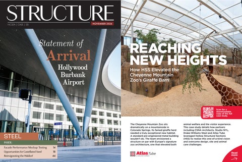
REACHING NEW HEIGHTS How HSS Elevated the Cheyenne Mountain Zoo’s Giraffe Barn
Scan for a downloadable copy of the full case study.
STEEL INSIDE: Facade Performance Mockup Testing Opportunities for Castellated Steel Reinvigorating the Waldorf
14 18 44
The Cheyenne Mountain Zoo sits dramatically on a mountainside in Colorado Springs. Its famed giraffe herd needed a truly exceptional new habitat. A standard pre-engineered metal building wouldn’t do. The team envisioned a structure on par with Europe’s signature zoo architecture, one that elevated both
animal welfare and the visitor experience. This case study details how partners including CSNA Architects, Studio NYL, Drake-Williams Steel and Atlas Tube leveraged Hollow Structural Sections (HSS) to realize this one-of-a-kind vision and overcome design, site and animal care challenges.
Read more
A Complex Vision on a Challenging Site From conception, the goal was to create a barn that embodied architectural excellence, prioritizing aesthetics while also directly serving the unique needs of the giraffes and their keepers. Among the project’s challenges were: • Complex Design: The zoo sought an iconic, transparent structure filled with natural light— necessitating a bold, unobtrusive framework. • Budget Constraints: Early iterations with curved steel tubes proved too costly, almost undermining the project. • Site Limitations: The steep mountain setting and tight footprint imposed logistical and scheduling restraints, complicated further by weather. • Animal Safety and Cleanliness: There was a strong directive to avoid surfaces that collect dust and to ensure smooth finishes, reflecting a top priority on animal safety and facility hygiene.
it needed to be done by the fall of 2025 so the interior could be completed before the following summer. Keeping up with an aggressive steel fabrication and erection schedule throughout 2025, the project team accomplished the goal to keep construction on track.
• Rapid Construction: The constant HSS radii of the HSS arches allowed for efficient HSS production, fabrication and erection, an advantage as crews raced against mountain winter weather to seal in the habitat.
Rectangular HSS delivered unmatched design elegance and construction efficiency, with 24x12 and 30x10 as the primary sizes in the structure. “With HSS, we could create those long, beautiful spans and graceful arches you see inside the barn, while minimizing the number of interior columns—features that make the space feel genuinely open and natural for the giraffes,” noted Julian Lineham, Founding Principal at Studio NYL.
The Cheyenne Mountain Zoo’s Giraffe Barn is more than an engineering accomplishment—it’s a monument to what’s possible when design innovation, resident welfare and construction expertise come together. Leveraging jumbo section HSS members allowed the team to craft a landmark habitat: expansive, sunlit, safe and natural. Guided by the voices of architects, engineers, animal caregivers and steel fabricators, the barn demonstrates that with the right material and the right vision, we can bring a piece of the wild to the heart of Colorado—delighting visitors and enriching the lives of the animals who call it home.
Beyond safety, the flat surfaces of HSS prevent the buildup of dust—a point mentioned repeatedly by the zoo’s CEO and animal care team. “Using rectangular HSS, alongside a programmable rain system inside the habitat, means less dust from the giraffes’ hooves and an easier environment to maintain—not just for the enjoyment of zoo patrons, but more importantly, for the giraffes’ health,” said Friesen.
The Solution: HSS as the Structural and Architectural Keystone Hollow Structural Sections became the linchpin of the habitat design, replacing more expensive clear-span, round tube lenticular trusses with a series of robust HSS arch frames supporting an expansive ETFE roof. The decision to use HSS solved budgetary and functional demands, while facilitating aesthetic possibilities that set the barn apart from other enclosures. This pivotal choice was crucial to support the grand opening in June 2026. Because the ETFE roof could not be installed in cold or windy weather,
profiles that have sharp flanges or corners, HSS profiles present smooth, gentle curves. This design detail proved crucial: one of the top priorities of zoo leadership and the project team was to ensure that any structural steel used would not be able to scratch, cut or otherwise hurt the giraffes.
The long, sweeping arches mimic the horizon lines and broad skies of the giraffes’ native habitat, immersing animals and visitors alike in an environment reminiscent of the wild. “This is now the largest ETFE-roofed animal care facility in the Western Hemisphere, and other zoos are planning to follow suit,” said Gregory Friesen, Owner at CSNA Architects Colorado Springs. “Sunlight pours in from every angle. For the guests and, more importantly, the giraffes, it doesn’t feel like a zoo—it feels like open country.” Critical MEP materials were run across the top of the HSS to blend into the structure, preserving the interior’s uncluttered, natural effect.
Exceptional Safety and Animal Welfare A signature benefit of HSS was that they provided animal-friendly surfaces. “We wanted a structure that was not just iconic, but one that truly promoted the well-being of the animals. HSS gave us both—elegance and peace of mind for animal safety,” said Friesen. Unlike some steel
Results: A Landmark Structure • Natural, Wild-Like Habitat: The barn’s transparent, soaring roof and open spans truly evoke the African plains—creating not just a shelter, but a vibrant ecosystem. “The animals respond to the natural light, space and fresh air. It feels wild—not like an exhibit,” said Friesen. • Unparalleled Animal Safety: The smooth, uninterrupted surfaces of HSS eliminate sharp edges, ensuring complete safety for the giraffes. “We turned out some really beautiful structural steel,” said Maryann Davis, Estimating Manager with Drake-Williams Steel. “One of the primary concerns was to use steel members that wouldn’t scratch the giraffes, which doesn’t come up in many project specifications.” • Efficient, Clean, Timeless Design: Smooth, closed shapes and minimized dust accumulation highlight the barn’s functionality. • Cost-Effectiveness: The innovative HSS approach brought the iconic vision within financial reach, saving on both material and erection costs.
Sean Boyd of Drake-Williams Steel added, “Working with Atlas Tube was a fantastic experience—they were attentive, responsive and genuinely invested in the success of this project. Their dedication helped us deliver an outstanding result for the zoo and its giraffes.”
Project Team: Architect: CSNA Architects Structural Engineer: Studio NYL Fabricator: Drake-Williams Steel HSS: Atlas Tube
Visit atlastube.com/heights to try Atlas Tube’s complimentary HSS design tools or discuss your design goals with our engineering experts.
ADVERTISER index
Please support these advertisers
Applied Bolting.............................................................17 Atlas Tube............................... Front Cover Gatefold Bull Moose Industries ............................................... 24 Cast Connex .......................................................................................5 CSI -Computers & Structures, Inc. .............Back Cover Degenkolb.............................................................................................3
DEWALT ..........................................................................7 ENERCALC .....................................................................9 IES.....................................................................................12 NUCOR ..............................................................................................54 Steel Dynamics............................Inside Back Cover
STRUCTURE
®
CIRCULATION
subscriptions@structuremag.org
EDITORIAL BOARD Chair John A. Dal Pino, S.E. Claremont Engineers Inc., Oakland, CA chair@STRUCTUREmag.org Kevin Adamson, PE Structural Focus, Gardena, CA Marshall Carman, PE, SE Schaefer, Cincinnati, Ohio
November 2026 Digital Issue
Erin Conaway, PE AISC, Phoenix, AZ Sarah Evans, PE Walter P Moore, Houston, TX Steven Judd Interstate Brick, West Jordan, Utah, and H.C. Muddox, Sacramento, California
Available Only at
Linda M. Kaplan, PE Pennoni, Pittsburgh, PA
STRUCTUREmag.org
Jessica Mandrick, PE, SE, LEED AP Gilsanz Murray Steficek, LLP, New York, NY Brian W. Miller Cast Connex Corporation, Davis, CA
Publication of any article, image, or advertisement in STRUCTURE magazine does not constitute endorsement by NCSEA, CASE, SEI, the Publisher, or the Editorial Board. Authors, contributors, and advertisers retain sole responsibility for the content of their submissions. STRUCTURE magazine is not a peer-reviewed publication. Readers are encouraged to do their due diligence through personal research on topics. ®
Evans Mountzouris, PE Retired, Milford, CT Kenneth Ogorzalek, PE, SE KPFF Consulting Engineers, San Francisco, CA (WI) John “Buddy” Showalter, PE International Code Council, Washington, DC Eytan Solomon, PE, LEED AP TYLin, New York, NY
EDITORIAL STAFF Executive Editor Alfred Spada aspada@ncsea.com
Managing Editor Shannon Wetzel swetzel@structuremag.org
MARKETING & ADVERTISING SALES Senior Director for Business Development & Marketing
ADVERTISEMENT–For Advertiser Information, visit STRUCTUREmag.org
Monica Shripka Tel: 773-974-6561 monica.shripka@STRUCTUREmag.org
Sales Manager TaVodrick Cottonham Tel: 847-900-9750 TCottonham@ncsea.com STRUCTURE magazine (ISSN 1536 4283) is published monthly by The ®
National Council of Structural Engineers Associations (a nonprofit Association), 20 N. Wacker Drive, Suite 750, Chicago, IL 60606 312.649.4600. Periodical postage paid at Chicago, Il, and at additional mailing offices. STRUCTURE magazine, Volume 33, Number 11, © 2026 by The National Council of Structural Engineers Associations, all rights reserved. Subscription services, back issues and subscription information tel: 312-649-4600, or write to STRUCTURE magazine Circulation, 20 N. Wacker Drive, Suite 750, Chicago, IL 60606.The publication is distributed to members of The National Council of Structural Engineers Associations through a resolution to its bylaws, and to members of CASE and SEI paid by each organization as nominal price subscription for its members as a benefit of their membership. Yearly Subscription in USA $75; $40 For Students; Canada $90; $60 for Canadian Students; Foreign $135, $90 for foreign students. Editorial Office: Send editorial mail to: STRUCTURE magazine, Attn: Editorial, 20 N. Wacker Drive, Suite 750, Chicago, IL 60606. POSTMASTER: Send Address changes to STRUCTURE magazine, 20 N. Wacker Drive, Suite 750, Chicago, IL 60606. STRUCTURE is a registered trademark of the National Council of Structural Engineers Associations (NCSEA). Articles may not be reproduced in whole or in part without the written permission of the publisher.
NOVEMBER 2026
3
Contents
N OV E M B E R 2 0 26
MODERN CONVENIENCE, TIMELESS APPEAL By Todd Elayer, SE, Al Schuchard, SE, and Phil Petermann
28
The $1.3B Replacement Passenger Terminal Project replaces a 96-year-old facility with a vibrant, Hollywood-inspired hub that enhances the airport’s cherished convenience.
F E A T U R E S STRUCTURAL SOLUTIONS BEHIND TD TERRACE By Cait Mancuso, P.Eng.
34
ELEVATING STUDENT HOUSING ABOVE PEOPLE'S PARK
By Leo Panian and Gregg Novicoff
38
From its sloping columns and terraced setbacks to its striking curved crown, TD
The Judith E. Heumann House, a 12-story, 328,000 square-foot UC Berkeley
Terrace showcases how engineering ingenuity and collaboration brought a
dormitory, addressed unique considerations and challenges to integrate with the
landmark addition to Toronto’s skyline to life.
established neighborhood.
A DECADE AT THE WALDORF By Alastair C. Elliott, PE, and Victoria Ponce de Leon, PE
44
SEEING THE TREES FOR THE FOREST
50
The redevelopment of the Waldorf Astoria New York represents a
By Paul Kassabian, PE, Michael Richard PE, Emma Ramsden PE, and Blerina Doucette
comprehensive structural rehabilitation and adaptive reuse of one of New York
The new National Conservation Legacy Center in Missoula, Montana, is
City’s most iconic historic buildings.
a building-as-exhibit featuring and representing wood species and wood products from across the USA. It educates the public about the history and ongoing conservation work of the United States Forest Service (USFS).
4
STRUCTUREmagazine
CONNECT SEAMLESSLY
CAST CONNEX® Diablo Bolted Splice™ (DBS) is a cast steel fitting that enables unobtrusive field bolted splices in circular hollow structural section (HSS) members.
Seamless DBS splice connectors are offered with thin-gauge plates to conceal the splice, although they can
Effortless to use as it eliminates field welding, and expertly designed such that the bolted connection is inboard of the outer diameter of the HSS.
Easy to Specify pre-engineered solution, available in sizes to fit a range of HSS/Pipe. Request sample specification and download Datasheets at: www.castconnex.com.
be left uncovered.
CTA DAMEN GREEN LINE STATION | Chicago, IL Architect: Perkins&Will Structural Engineer: Simpson Gumpertz & Heger Inc. Steel Fabricator: Lockport Steel Fabricators General Contractor: F.H. Paschen, S.N. Nielsen
DIABLO BOLTED SPLICE™ info@castconnex.com | 1-888-681-8786
www.castconnex.com
C O L U M N S a n d D E PA RT M E N TS
8
Editorial
10
From Project Engineer to Project Manager By Andrew Dolan, PE, SE
10 Structural Influencer 14 Structural Design Ron Hamburger
Structural Loading in Facade Performance Mock-Up Testing By David Fratamico, Ph.D, PE, and Kyle Berg, PE
14
18 Structural Design
Opportunities for Castellated Steel in Framing Solutions By Brandon Bell and Jack Koehler, PE, SE
22 Structural Design Beyond the Finish By Cabot Wilkinson
25
Structural Design
From Drawings to Installation: Best Practices for Power-Actuated Fastener Selection
18
By Vinay Damam, PE, and Stephanie Ecker, PE
55 Codes and Standards
2027 IBC Significant Structural Changes: Structural Design (Chapter 16)—Construction Documents, Load Combinations and Live Loads By John “Buddy” Showalter, PE, Sandra Hyde, PE, and Karyn Beebe, PE
60 InSights
The Venezuela Earthquakes: An Uncomfortable Reminder for Structural Engineers
60
By Ana Sarkis Fernandez
62 InSights
(Re)building Bridges By Lili Boenigk
73 6
Business Practices
Meeting the Standard of Care By John Tawresey
STRUCTUREmagazine
In Every Issue 3 Advertiser Index 64 NCSEA News 66 CASE in Point 68 SEI Update 70 SE News
SCAN TO LEARN MORE
CORROSIVE RESISTANT STAINLESS STEEL OFFERINGS SCREWBOLT+ HIGH PERFORMANCE SCREW ANCHOR
WEDGE ANCHORS POWER-STUD®+ SD4/SD6 HEX HEAD
STAINLESS STEEL UNC THREADED BOLT
TM
MANDREL
INTEGRATED WASHER
WITH SERRATIONS UNDER THE HEAD SECURES THE ATTACHMENT
STANDARD BIT WASHER
ICC-ES APPROVED "EVERYDAY" WEDGE ANCHOR
CARBON STEEL EXPANSION WEDGE (CLIP)
DESIGNED FOR ANSI CARBIDE DRILL BITS
ENGINEERED STEE L
DESIGNED TO CUT THROUGH HARD CONCRETE AND MAINTAIN DUCTILITY
APPROVALS
DUST RELIEF THREAD PROFILE
IMPROVES SPEED AND REDUCES EFFORT FOR FAST INSTALLATION
I
ICC-ES ESR-2502 Concrete
2024 2021 2018 2015
Recognition in cracked and uncracked concrete including seismic and wind loading (Category 1 Anchors)
FM & UL listings: www.DEWALT.com
BASE MATERIALS
Normal Weight Concrete
Lightweight Concrete
Grouted Masonry
Concrete Over Steel Deck
COMING SOON IN STAINLESS STEEL
DOWNLOAD THE FULL FREE SUITE AT DEWALT.COM/DDA
©2026 DEWALT.
EDITORIAL From Project Engineer to Project Manager By Andrew Dolan, PE, SE
M
ost structural engineers measure early- adjustments. Holding on to every technical career progress by the difficulty of the task feels efficient, but it limits the team’s problems they can solve, and for good reason: capacity and denies junior engineers the a solid technical base is the foundation of a experience they need to lead. Delegating well successful career in structural engineering. So means matching work to experience, defining when the first project management assign- the deliverable, and scaling oversight to the ment arrives, it is easy to assume the hard part task’s risk rather than the engineer’s title. is over. It rarely is. Quite quickly, many new There is a reasonable case that project manmanagers face challenges that are not techni- agement is learned only by doing. Experience cal at all, whether from the client or from a is irreplaceable, and no seminar substitutes for change in budget or schedule. sitting across from a client whose project is That experience is common across the pro- over budget. That view deserves consideration. fession. Engineers build careers by mastering But learning purely by trial and error means codes, calculations, and increasingly com- learning on clients’ budgets and junior staff ’s plex structures, and then many are handed hours, and the cost shows up as overruns, responsibility for scope, fee, schedule, cli- rushed reviews, and burnout. Managing well ents, and staff, skills that receive far less is also not a retreat from technical engineerformal attention than design. Technical ing. It is an extension of it, applying the same proficiency does not automatically translate discipline of defining the problem, weighing into project leadership. The move from proj- constraints, and making sound decisions to ect engineer to project manager is a change scope, schedule, and fee. A manager who proin responsibility, not tects the fee protects the simply a promotion, hours needed for careA manager who protects and it goes best when ful design and thorough the fee protects the engineers approach it review. Good project deliberately: by owning management is what hours needed for careful their growth, seeking makes good engineering design and thorough out the right menpossible on schedule and review. Good project tors, drawing on the on budget. management is what collective experience No one hands a new makes good engineering of colleagues within project manager a curpossible on schedule and their firm, and buildriculum. Firms can ing a network of peers provide opportunities, on budget. through structural and some have internal engineering profesprocesses to support the sional organizations transition, but engineers and code development committees. must own their development. That starts A project engineer’s success is measured while they are still project engineers, by asking by the quality of their own work. A project questions: how fees are developed, how client manager’s is measured by the performance of relationships are built, who outside the firm the entire team, and by whether the project takes part in project meetings and why, and succeeds as both a technical undertaking and a how the budget is tracked over the course of a business commitment. An additional analysis, project. The list goes on. Young engineers also a revised framing layout, or a series of archi- need to seek out mentors, and the most protectural changes may each seem manageable ductive mentoring relationships often begin alone; together they can consume the project’s because the less experienced engineer asks. hours. A project that has used 70 percent of Support from outside the firm matters, too. its fee but still needs substantial coordination Alongside strong mentors at my own firm, I and revisions is at risk, even if the drawings have found that the Coalition of American look nearly done. The question is not how Structural Engineers (CASE) offers somemuch budget has been spent, but what it will thing no single firm can: perspective from take to finish. across the profession. Serving on the CASE Delegation is often one of the hardest Executive Committee has been a way to share
8 STRUCTURE magazine
knowledge about project management and to hear how structural engineers around the country handle the same challenges. Problems that feel unique, from scope creep to difficult client conversations, turn out to be shared across the profession, and others have already faced them and can pass along what they learned. These lessons can become routine practice: confirm scope, budget, and assumptions at the start, track progress against remaining effort throughout, and record lessons at closeout. The benefits reach well beyond the bottom line: earlier intervention on budget problems, fewer late pushes that compromise quality, junior engineers who grow into leaders, and clients who trust that problems will be raised in time to solve them. Firms can support this transition by treating project management as a skill to be developed, not a responsibility that arrives with seniority. But engineers making the move should not wait. Ask for the experience. Find the mentors. Use the resources CASE and its members have built, and, when ready, contribute to them. The best project managers do more than deliver sound designs; they create the conditions for their teams to do their best work. That is a skill worth learning on purpose. ■
Andrew Dolan, PE, SE, is an Associate Partner at Gilsanz Murray Steficek in New York, where his work spans new construction and renovation, including several recent office-to-residential conversions. He is a member of the CASE Executive Committee and holds an MS in Civil Engineering from Virginia Tech and a BS in Civil Engineering from Manhattan College. He can be reached at andrew. dolan@gmsllp.com.
structural INFLUENCER Ron Hamburger, PE, SE W
ith more than 50 years of experience practicing structural engineering, Ron Hamburger, PE, SE, is an internationally known expert and leader in earthquake design and structural performance evaluation. From his early roles in earthquake consulting at EQE International to serving as senior principal of Simpson Gumpertz & Heger, Hamburger has used his engineering acuity to design safe structures and help guide others in the profession to do the same. Additionally, Hamburger has served on various committees and engineering societies, including as president of NCSEA, SEAOC, SEAONC, SECB, and a member of the SEI Board of Governors. STRUCTURE approached Hamburger to talk about his career path and gain his perspectives on codes and standards, performance-based design, and mentorship. STRUCTURE: Your first employment was in the design of industrial structures. What lead you into earthquake disaster investigations and retrofitting buildings damaged by earthquakes? Ron Hamburger: My move from designing heavy industrial facilities to specialty earthquake consulting was driven by the global economy. The U.S. was in serious recession, and my employer was engaged in massive layoffs. My move to EQE International was an economic necessity. I had recently earned my MBA and had mostly been performing managerial tasks at Bechtel. EQE hired me as a project manager, which I naively assumed was primarily a management role. I quickly learned that at EQE, project managers performed mostly technical tasks and relatively little actual management. Fortunately, as I began to investigate earthquakes and evaluate real buildings, I became fascinated, both by the destructive power of earthquakes and the inability of many typical building designs to cope with them. I also enjoyed being able to contribute to improvement in the codes and standards. Earthquake engineering became an avocation as well as an occupation. More importantly, I learned that my true value was in my engineering skills and knowledge, not management. Though I continued to take on management roles at EQE, and later Simpson Gumpertz & Heger (SGH), I never again walked away from active engagement in engineering. STRUCTURE: Starting with EQE, you have been part of growing structural engineering practices. What were the key ingredients for growth and the effort involved? Hamburger: Both EQE and SGH grew substantially during my tenure at these firms. Both firms thrived and grew because of three common business approaches. First, to diversify the services provided and the clients served. EQE offered primarily earthquake risk management services, but did so to government agencies, and the commercial real estate, lending, nuclear power, and manufacturing industries. This proved to be a recession-resistant strategy as it was rare that all these client types would simultaneously experience a downturn. Similarly, SGH offers design, investigation, and rehabilitation services, primarily in the structural and building envelope areas, but like EQE, for a wide range of clients. We have found that as the economy shifted, one or more of these lines of activity would be “hot” while others cooled down. Both firms deliberately avoided becoming “one-trick ponies” and 10 STRUCTURE magazine
avoided the periodic staff reductions common in many engineering firms. Thus, when economies improved, we were able to grow rather than just rebuild to previous levels. Second, both firms offered highquality services at non-commodity prices and were willing to walk away from work if there was not sufficient budget to do the job right. This provided us with the resources needed to attract and retain top talent. The third strategy, and the one most responsible for both firms’ growth: hire really smart people and give them responsibilities and rewards associated both with developing clients and executing the work. Both firms were eager to hire principal-level people if they shared the firms’ culture and had a record of successful sales and execution at a high level. This resulted in incredible growth at both firms. STRUCTURE: As the lead investigator into the Twin Towers collapse, what lessons can you share about how to participate in such an effort? Hamburger: Gene Corley led the overall investigation team. Although I ended up as lead author for Chapter 2 of the FEMA 403 report, it was a highly collaborative effort. The FEMA/BPAT (Federal Emergency Management Agency/Building Performance Assessment Team) team included 30 engineers from practice and academia including structural and fire protection engineers, metallurgists, and fracture mechanics experts. The group worked as a team, walked the site, reviewed drawings, videos and photographic evidence, and met frequently to discuss observations and suggest theories. Mostly I stayed quiet during this period and listened. Then, after a few days, under Gene’s guidance, we self-organized into a series of sub-teams
that would study specific aspects of the events in more detail when the team dispersed and individuals returned to their home bases. Having visited the towers while they were under construction, as part of an ASCE student chapter field trip, I raised my hand to participate, as did Bill Baker, a structural engineer with SOM and Jonathan Barnett, a fire protection engineer. Bill and I were given the building drawings, and we each worked with our firms’ staff to perform simplified analyses of the buildings to try to understand what had happened and why. The three of us would communicate frequently by phone and email. The overall team reassembled every few weeks, and each team member would present what they had found. Then we would spend time as a group discussing the information and trying to draw conclusions. Finally, when it was time to write the report, I Ron Hamburger, at the wheel of the pickup truck, discusses the findings on site of an earthquake investigation in volunteered to write a first draft, working Costa Rice in 1991. with Bill and Jonathan. Comments came to me and I incorporated them. remaining calm and solving problems was the best course. Fortunately, Really, the effort was much like the work I had previously done on my partners at SGH and our client gave us the support and resources code committees. I volunteered information and thoughts, when I needed to do the job right. thought they had value, and stayed quiet and listened to others. I worked in areas where I felt I had talent (structural analysis, structural STRUCTURE: How and why did you become so involved in the behavior, writing) and interest. This has been a formula for success development of codes and standards? throughout my career. Hamburger: I had the fortune to have employers who encouraged their staff to be professionally active; I started my activity at a time STRUCTURE: You were the lead engineer on the retrofit of the of great change in the earthquake engineering field and building Millennium Tower in San Francisco. How did you deal with the stress codes; I found that I greatly enjoyed being able to contribute to the and constant attention to your work in the media? profession and make an impact. Having both the opportunity and Hamburger: The stress was significant, and media attention was only desire, I worked diligently on these various committees and projects. one source of it. Other pressures included an exhaustive peer review My colleagues found my contributions valuable and through wordthat produced nearly 200 detailed questions; criticism and questions of-mouth additional opportunities were made available to me. If an submitted to the building department by other engineers, acting on opportunity arose that sounded interesting and which I also believed their own initiative; my engineering team that seemed to uncover a was important, I never said no. new, seemingly unsolvable design problem almost weekly; and lastly, my wife of 36 years lost a 5-year struggle with cancer at the start of STRUCTURE: What do you think is the biggest misconception engithe work. Actually, the project helped to pull me out of the funk that neers have about the development of codes and standards? followed my loss by giving me something else to think about. Then I Hamburger: The biggest misconception is that the committees are met the woman who would become my second wife, and this changed dominated by professors who don’t understand the realities of design my attitude as well. I handled the media-induced stress by trying to and who make changes to justify their research, without concern for ignore the articles and news commentary unless our client asked that I the practicing engineer. The reality is very different. While some help them frame a formal response. We responded to each of the peer academics are involved in code and standards development, the ANSI review (and external engineer) comments by conducting additional standard process requires that these committees have a balanced studies and presenting the results for further review. Fortunately, on representation of consumers (engineers), producers (contractors and this project, budget was not an issue. When my engineering lead came industry representatives), and general interest (academics, building to me with a seemingly unsolvable problem, I tried to maintain calm, officials, insurance industry representatives, etc.) and by far the group sit with him and the team to talk through the problem, and guide with the greatest representation and influence tends to be practicing them to find additional ways around the problem. Sometimes, we engineers. For example, the ASCE 7-22 committee had 53 voting would reach out to professors I knew at UC Berkeley or Stanford. members. Of these, 21 (40%) were practicing engineers and only Fortunately, I had a great team, and with a little encouragement and seven (13%) professors. I do need to acknowledge however, that positive support, we were able to overcome the technical hurdles we though small in number, the academics on these committees make encountered. many valuable contributions. I don’t believe I would have been as successful at holding the team together earlier in my career. Approaching 50 years of practice, I STRUCTURE: Many engineers think codes and standards have had seen adverse circumstances on projects before and knew that become more complex and voluminous, with little practical benefit or NOVEMBER 2026
11
improvement in the design. What are your thoughts on this? Hamburger: I agree, and for years have advocated for making changes that introduce complexity only when necessary to fulfill the code’s life-safety intent. I have largely been unsuccessful. The drivers for adding complexity are first to make it possible to build more economical structures and second to reliably protect life safety. Unfortunately, it seems impossible to shave the margins inherent in design down, i.e., decrease construction costs; assure that the probability of failure remains low; and keep the code simple. I like to say everyone wants safe, simple, and economical codes, but you can only have any two. If you want the code to be safe and simple, it won’t be economical; if Ron Hamburger (second from left) joins the project crew atop a refinery structure in Trinidad in 2018. you want it safe and economical; it won’t be simple, and if you want it simple and economical, it won’t be safe! In my time on them, the committees have building code and AASHTO bridge design standards. always opted for economy and safety at the expense of simplification. We can and increasingly do learn without failures through academic research, both analytical and empirical. But research-based lessons STRUCTURE: Which failures have had the greatest influence on are often slow to be codified, and sometimes don’t make it into the codes? Can we learn without failures? code until after a disastrous failure occurs, because engineers on code Hamburger: Learning from failures has been a major driver for committees want proof that a real problem exists before acting. The our codes and standards, since their inception. In fact, the original exception is when the research points to a more economical way of building codes were largely comprised of lessons learned from failures doing things. and admonition to designers not to repeat past mistakes. It is hard to point to any one failure as having had the most impact on our codes. STRUCTURE: You have demonstrated a long and dedicated comHowever, I would have to say that within my lifetime, the 1971 San mitment to structural codes and standards. If you could point to one or Fernando earthquake was the “event” that had the greatest impact. two things that people will long say “Thank God Ron was involved with The failure of hospitals in that event led to the adoption of occupancy this” what would they be? importance categories and factors. The failure of code-conforming Hamburger: I don’t know that any engineers would say that, however, I structures led to the National Earthquake Hazards Reduction pro- personally believe that my most significant contribution has been in the gram and the complete rewrite of the seismic provisions in both the development of performance-based design (PBD) provisions over the past 30 years. This initiated my work on the ATC-33 project to develop seismic rehabilitaADVERTISEMENT–For Advertiser Information, visit STRUCTUREmag.org tion guidelines (now ASCE 41) and extended into my work with SEAOC’s Vision 2000 project and the FEMA/SAC Guidelines, the YOU PEER TBI Guidelines for Performance-based Optimize the footing: increase Seismic Design of Buildings, the addition of both dimensions in 0.5 ft quantitative performance goals to Chapter 1 increments until bearing passes. of ASCE 7, development of the ASCE Prestandard for Performance-based Wind Design NATURAL-LANGUAGE ENGINEERING and finally as Director of the ATC-58 project DESIGN UNITY VALUE 01 Bump the thickness. to develop next-generation performancebased seismic design procedures. The ATC-58 1.71 1.38 1.15 0.97 02 Re-run. PASS project is the basis for the functional recovery 03 Check the unity. Decided by the program. Never by AI. requirements for seismic design that will likely 04 Repeat. appear in ASCE 7-28 as a non-mandatory procedure. I was able to do this because I had both practical structural design experience and See it live. knowledge of structural reliability methods. Many others made important contributions to these efforts. Noteworthy among these are iesweb.com/intelligence Charley Kircher, Bill Holmes, Jim Harris, Example prompts are illustrative. Available actions depend on the supported IES program and the current model. Helmut Krawinkler, Allin Cornell, Jack Moehle, John Hooper and Ron Klemencic.
Now the loop is a sentence.
12 STRUCTURE magazine
Ron Hamburger (left) reviews drawings with Keith Palmer, a project manager at SGH.
Ron Hamburger (right) visits the site of the Millennium Tower retrofit foundation with the contractor’s supervisory personnel.
STRUCTURE: How do you view the future of performance-based structural design? Do you envision it replacing prescriptive design in the near future? Hamburger: I have spent much of my career developing performance-based design (PBD) procedures and regard it as my greatest accomplishment. Important advantages of PBD is that it: 1. Allows us to design structures that are not envisaged by, or do not fit the present provisions of building codes. 2. Enables the safe introduction of new structural systems and materials to our toolbox. 3. Enables us to verify that our present or proposed building code provisions are actually capable of providing the intended reliability. Its use has already become routine in the design of new high-rise buildings in regions of high seismicity worldwide and seismic evaluation and retrofit of buildings. Its use in fire protection design, and wind design is gaining popularity. As software and AI capability continue to improve, I am confident PBD will see increasing use. However, I don’t believe PBD will ever entirely replace prescriptive design for routine structures for several reasons. First, structural design is a highly competitive business and for routine structures, the market will not bear the extra costs associated with the additional time, knowledge, and resources required to perform PBD. Second, the use of prescriptive procedures defines the current standard of care. By conforming to this standard, engineers reduce the risks associated with design. When performing PBD, engineers may step outside the standard of care and expose themselves to greater risk. This will dissuade many engineers from taking this practice on.
STRUCTURE: What do you think is the biggest challenge facing our profession in the next 10 years? Hamburger: I believe the biggest challenge facing our profession is the same as that faced by our nation. Young engineers, entering the profession, as with all American youth need to share the values that helped to build a strong and exceptional America. Engineering is hard work; it’s not an easy job. It can be extremely rewarding if you are willing to put in the effort and not be afraid to think critically. I hope that the next generation will understand this.
STRUCTURE: What advice would you give to young engineers, and what attributes should young engineers have today versus in the past? Hamburger: Don’t think of structural engineering as a 9-to-5 job and that your college degree provides you all the knowledge you will ever need to practice. Structural engineering is a profession. To be successful at it, an engineer needs to invest personal time to remain abreast of and understand new developments and be committed to performing quality work. In addition, networking with other engineers in and outside your firm is essential to growing your personal knowledge and skills. Involvement in professional committees is a great way to do this, and helps to give back to the profession, something all professionals should do.
STRUCTURE: We all have mentors and people who have influenced and helped us. Who would you like to thank and why? Hamburger: In 1990, the Standard Oil Company of California (Chevron) hired EQE to perform a seismic evaluation of their corporate headquarters building in San Francisco, a 1920s vintage, 24-story steel frame building with infill unreinforced masonry. I proposed a performance-based design approach in the evaluation, employing static pushover analysis, which was used in the offshore petroleum industry but not yet for buildings. Chevron was of course familiar with the approach and endorsed it but required that we have an expert peer review panel to give the analysis and findings credence. Chevron retained Professors Vitelmo Bertero and Egor Popov of UC Berkeley, Helmut Krawinkler of Stanford, Joe Nicoletti a Principal Emeritus at URS/Blume, and Dan Shapiro, president of a locally prominent SE firm. I was a newly minted SE, who had recently joined EQE from Bechtel and had not yet become professionally active. The panel treated me with respect and deference, and collaboratively helped us to perform the analysis, and ultimately, upgrade of the building. These panel members became colleagues and friends with whom I had many later associations. They taught me what it meant to be a professional. STRUCTURE: What do you enjoy most when not doing engineering? Hamburger: I enjoy reading historical fiction and autobiographies of historically important people. A good read I recently finished was “At Ease,” President Eisenhower’s casual memoirs covering his youth, military service, U.S. Presidency and retirement. STRUCTURE: Lastly, what is your favorite ice cream? Hamburger: Vanilla. ■ NOVEMBER 2026
13
structural DESIGN Structural Loading in Facade Performance Mock-Up Testing
Project teams can identify and resolve design, fabrication, or installation issues before full production, when changes become much more costly and disruptive. By David Fratamico, Ph.D, PE, and Kyle Berg, PE
E
xterior cladding for mid-size and high-rise buildings is an important aspect of whole building design. Architects, clients, and engineers spend a significant amount of time discussing the unity of architectural expression, structural and thermal performance, and efficiency of design. Structural engineers in the curtain wall/facade engineering field help to collaboratively design exterior cladding that meets stringent project specifications and performance requirements, while also working to maintain the integrity of a building’s cladding system for the building’s service life. Performance mock-up testing is frequently completed on many projects to assess cladding system performance and provide the project team with an opportunity to refine the design, fabrication, and installation of the system. A common type of cladding system used in a mid to high-rise structure’s facade system is unitized curtain wall: modular units (typically 5 feet wide by 15 feet tall) that are factory assembled and then shipped to site and installed with a small installation crew of 3-5 ironworkers rather than the complete assembly of facade systems on site (referred to as stick-built curtain wall). Using a unitized approach offers enhanced quality assurance and control (as units are assembled in a factory environment with controlled processes), as well as increased cost effectiveness with the reduction of field labor. Units are shipped to site in crates and then “de-crated” on each floor of a building and individually installed via proper mating of unit framing elements and gaskets with those of adjacent units. This approach helps form a fully enclosed, air and watertight building cladding system. Figure 1 shows a standard curtain wall section view and an example of curtain wall installed on a building. For custom unitized curtain walls, the design is unique for every project. Curtain wall manufacturers such as New Hudson Facades (NHF) will commonly use custom aluminum extrusion profiles, custom gaskets and seals of varying materials, and proprietary strategies
to achieve optimal system performance. On larger towers (where over 500,000 square feet of curtain wall may be required), there may be a substantial cost and disruption associated with modifying the system once fabrication or installation is underway; the performance mockup phase provides the project team with an opportunity to identify and resolve necessary design, fabrication, and installation refinements before the system enters full production. Testing is conducted according to industry standards developed by ASTM International alongside the American Architectural Manufacturers Association (AAMA), which is now part of the Fenestration and Glazing Industry Alliance (FGIA). The project-specific curtain wall system is evaluated through a performance mock-up unit (PMU) testing program at an independent, third-party facility. The testing involves participation from the broader design and construction team—not solely the curtain wall contractor—to assess whether the system meets project-specific performance criteria. Although the overall goal is to pass all ASTM and AAMA tests to substantiate adequate air, water, and thermal performance for each unique curtain wall system, a PMU test offers practical insight on how every new system works; the mock-up demonstrates how the units will be installed most efficiently in the field, provides new ways for improving air/water/thermal performance at key locations on the wall, and gives an opportunity to conduct additional testing scopes for special project requirements or research purposes.
The Mock-Up: A Full-Scale Prototype of a Facade System A PMU is a full-scale assembly of actual curtain wall units selected to represent the predominant cladding system on a given project. It often combines the most recurring unit types along with atypical design features. The architect, facade consultant, general contractor, and clients collaborate to define the PMU scope and overall system performance. The arrangement of units is representative in nature and intended to incorporate unit sizes representing governing design conditions, such as taller and/or wider units, where loading on framing members and infill (e.g. glass or flat metal panels) is highest. The layout also mimics the juxtaposition of varying unit types and sizes on the building; the result is a full-scale prototypical representation of the overall facade. Test wall units are installed with anchorage to a base
Fig. 1. Shown is the schematic of a curtain wall to be installed on a high-rise building.
14 STRUCTURE magazine
steel structure (intended to mimic a typical tower’s structural system) and enclosed from behind by a test chamber wall. Figures 2 and 3 show elevations of two mockups: PMU-01 (tower system) and PMU-02 (lower level podium system). These are separate test walls for an 800-foot-tall skyscraper project located in the Hudson Yards neighborhood of Manhattan. Although curtain walls do not aid in the superstructure support system, they can be subject to transient and extreme loading from both natural and man-made sources. Structural loading on curtain walls takes multiple forms. The predominant structural loading for a typical mid- to high-rise building is wind loading. Commonly assumed to be an equivalent static load, wind loading is transient and variable over a building’s cladding surface. Other natural loads include snow, ice, and impact from wind-borne debris from hurricanes and tornadoes. On certain projects, artificial, or “man-made” live loads such as blast, ballistics, and forced entry can Figs. 2-3. The PMU-01 (tower system) test chamber is on the left, and the PMU-02 (lower level podium also be considered and tested to meet client system) test chamber is on the right. needs. Curtain wall systems are also required to withstand building movements from wind, seismic, and thermal and Other Structures) Chapter 30 provides analytical procedures loading. On projects without an elevated risk of hazards, PMU tests are for components and cladding, while Chapter 31 addresses the wind typically limited to wind, thermal, and building movement. tunnel procedure. ASCE 49 (Wind Tunnel Testing for Buildings and Other Structures) details the requirements for conducting wind tunnel studies and interpreting results. Structural Loading: Simulating Wind Pressure Boundary layer wind tunnel studies are typically sought by the design team early on and involve creating scaled models of the building Wind loads are transient and represented in curtain wall by positive and surrounding structures on a rotating surface in a wind tunnel to inward pressures and negative outward (i.e. suction) pressures. For simulate upwind terrain and surface roughness local to a project site. tall, geometrically complex buildings, project-specific cladding pres- Local climate data used to derive wind tunnel air flow speeds includes sures are commonly developed through wind tunnel testing studies. the basic wind speed for 3-second wind gusts and probabilistic wind ASCE 7 (Minimum Design Loads and Associated Criteria for Buildings speeds based on random simulations of hurricanes/cyclones. This data is combined to create a statistical climate model which, when combined with empirical data from pressure sensor data installed on the scale model of the building during wind tunnel tests, is used to derive topographic maps of recommended wind pressures for each area of each elevation of a building as shown in Figure 4. Static pressures for PMU testing are typically equivalent to the “prevalent” negative and positive wind loads on the cladding. In the PMU test sequence, the “Uniform Structural Design Load Test” and the “Uniform Structural Overload Test” (where 150% of the test chamber pressures are applied for testing system integrity) reference these static pressures and are implemented per ASTM E330 (Standard Test Method for Structural Performance of Exterior Building Elements). Other static pressure differentials of lower magnitude are used in the test sequence to measure static air infiltration/exfiltration in the test chamber construction and for simulating wind driven rain in the “Static Water Penetration Test.” Dynamic wind pressures are also used in testing, specifically for water intrusion testing according to AAMA 501.1. Unlike the static pressure which is simulated with modifying the internal pressure of the test chamber with a blower, loads are directly applied on the PMU from the exterior in an unusual yet exciting approach. Curtain wall test facilities typically employ the use of a large fan—and even sometimes, a turboprop aircraft engine—that can produce a wind stream with velocities Fig. 4. Wind tunnel study scaled model and example elevation with adequate to produce a dynamic wind pressure high enough to create superimposed recommended cladding design wind loads. NOVEMBER 2026
15
an accurate representation of a wind-driven rain event on the facade; an example test setup is shown in Figure 5. Recalling the equation for velocity pressure from ASCE 7-22: qz=0.00256*Kz*Kzt*Kc*V2 (lbf⁄ft2 ) qz=0.613*Kz*Kzt*Ke*V2 (N⁄m2 ) where equivalent velocity pressure is proportional to velocity squared, dynamic wind pressures of up to 15 psf can be generated with windspeeds of at least 77 mph from the large fan for at least 15 continuous minutes. This informs the design team of a curtain wall’s performance under a simulated severe storm. All wind pressure testing results can be used to inform the design team about any additional upgrades to the system before mass production of units. They are also used to verify calculations for system performance, including stresses in critical load-carrying elements and connections, expected deflections for insulating glass units (IGUs), and rigidity of all exposed cladding elements. Further post-processing of test results can even be used in a performance-based design approach for envelope design.
Structural Loading: Simulating Building Movements Curtain wall units are installed on anchors located at floor slabs, shear walls, and columns; building structural movements such as interstory drift from wind and seismic loading, slab deflections, thermal expansion/contraction, and column shortening must be considered at the curtain wall joints. These gasketed joints between units are referred to as stacks. Curtain wall systems accommodate building movements by allowing for stack longitudinal slip, opening, and closing as shown in Figure 6.
Fig. 6. Curtain wall systems accommodate building movements by allowing for stack longitudinal slip, opening and closing.
To simulate base structure movements, hydraulic pistons are built into the mock-up steel frame. Horizontal building movement tests are conducted per AAMA 501.4 and require one level of the mockup to move a specified lateral displacement (typically provided by the engineer of record). The displacement represents the maximum elastic interstory drift from wind loading (typically under 0.5 inch, or H/400) or inelastic interstory drift from seismic loading (sometimes surpassing 3 inches). To pass these tests, glass breakage, torn silicone joints, dislodged cladding elements, and compromised connections cannot occur after a minimum of three cycles of movement. After the elastic movements, all air and water tests are repeated to ensure system performance has not been compromised. Relative vertical movement tests are conducted per AAMA 501.7 and simulate building movements that cause relative slip along vertical stacks, as well as horizontal stack opening and closure. A level of the test chamber is displaced upward and downward for three full cycles; pass/fail criteria are the same as those of the elastic horizontal movement tests, but the repeated air and water tests are conducted with the horizontal stacks in the open position, which represents a worst-case project condition. Thermal cycling tests per AAMA 501.5 are also performed on the whole PMU test chamber to understand system integrity under extreme climatic temperature fluctuations and to verify the design’s condensation resistance. Thermal cycling is performed from the outside with insulating enclosures and can range from temperatures below 0F and above 180F.
Example PMU Test Procedure
Fig. 5. A large fan is used to recreate a wind-driven rain event on the PMU-01 setup during the dynamic water penetration test.
16 STRUCTURE magazine
• • • • • • • •
Preload (ASTM E330). Static Air Infiltration/Exfiltration Test (ASTM E283). Static Water Penetration Test (ASTM E331). Dynamic Water Penetration Test (AAMA 501.1). Uniform Structural Design Load Test (ASTM E330). Repeat Static Air Infiltration/Exfiltration Test (ASTM E283). Repeat Static Water Penetration Test (ASTM E331). Repeat Dynamic Water Penetration Test (AAMA 501.1).
• • • • • • • • • • •
Interstory Differential Horizontal Parallel Movement Test (AAMA 501.4). Repeat Static Air Infiltration/Exfiltration Test (ASTM E283). Repeat Static Water Penetration Test (ASTM E331). Repeat Dynamic Water Penetration Test (AAMA 501.1). Interstory Differential Vertical Movement Test (AAMA 501.7). Repeat Static Air Infiltration/Exfiltration Test (ASTM E283)— stack remains open. Repeat Static Water Penetration Test (ASTM E331)—stack remains open. Repeat Dynamic Water Penetration Test (AAMA 501.1)—stack can sometimes remain open. Uniform Structural Overload Test (ASTM E330). Seismic Movement Displacement Test (AAMA 501.4). Thermal Cycling & Condensation Testing (AAMA 501.5, AAMA 507, and others).
Additional Structural Testing Opportunities Additional climatic testing on mock-ups can include snow/ice accumulation tests, hurricane missile/projectile testing (for product approval in certain jurisdictions), and even harmonic testing of cladding components that may be subject to dynamic instabilities and excess vibration under project wind loads. In fact, an additional testing scope for PMU-02 focused on the dynamic stability of full-height vertical fins (shown in Figure 3). Accelerometers were strategically placed along the height of the fin features to measure precise flexural and torsional movements of the fin during a dynamic air test. A spectral analysis of natural frequency
was then completed to aid the design team in calibrating a parallel finite element model, quantifying any potential for dynamic instabilities, and preventing unwarranted noise or vibrations. Point load testing can also be completed. Tests can simulate the impact of falling objects on cladding appurtenances and exposed features, or even the maximum expected loading in all cardinal directions at building maintenance unit tiebacks and guide tracks. Other tests can focus on the security design of curtain walls under threat of manmade hazards.
Summing It Up Performance mock-up testing evaluates how a custom, project-specific curtain wall system performs under the loads and movements it will experience in service and allows the project team to identify and resolve design issues before full production. Although the results apply directly to the tested assembly, a well-selected PMU provides valuable confirmation that the system can meet a project’s performance requirements. ■ The authors would like to acknowledge NHF Project Manager Don Tice for his mock-up photos at the test facility.
David Fratamico, Ph.D, PE, is a senior structural engineer with New Hudson Facades in Linwood, PA, with experience in testing and new product development. Kyle Berg, PE, is a structural engineering manager with New Hudson Facades in Mendota Heights, MN, with over 14 years of curtain wall design experience. He leads engineering teams in Minnesota and Pennsylvania.
ADVERTISEMENT–For Advertiser Information, visit STRUCTUREmag.org
4X 1.800.552.1999
1.802.460.3100
info@appliedbolting.com NOVEMBER 2026
17
structural DESIGN Opportunities for Castellated Steel in Framing Solutions This WWII workaround has been reimagined to enhance structural efficiency. By Brandon Bell and Jack Koehler, PE, SE
S
ometimes looking to the past gives you the best route forward. In the world of structural engineering, an innovative workaround originally developed during World War II steel shortages has stepped back into the spotlight to redefine modern commercial construction: castellated steel beams. In recent years, supply chain disruptions across the structural steel industry—driven by unprecedented warehouse and data center construction—forced commercial project schedules to adapt. When traditional bar joist lead times extended past 12 months and marketplace volatility surged, structural engineers and fabricators deployed alternative framing solutions to maintain project momentum. However, what began as a temporary supply-crunch strategy has revealed permanent, compounding structural efficiencies across highbay industrial footprints, retail anchors, multi-story Class-A commercial environments, steel and mass timber hybrid structures, and multi-level parking facilities. By combining modern 3D CNC automated plasma laser cutting with advanced robotic welding infrastructure, castellated steel beam framing solutions have evolved into a highly standardized, cost-competitive alternative to traditional open-web steel joists and cast-in-place concrete systems.
Manufacturing and Material Mechanics The core engineering advantage of a castellated beam lies in its geometric transformation. The manufacturing process begins with a standard hot-rolled wide-flange section (W-shape). An automated plasma cutter executes a continuous, mathematically optimized profile cut along the longitudinal axis of the web. The two resulting structural halves are separated, shifted by half a geometric pitch to align the high points of the cut, and re-welded at the web posts. This structural expansion increases the overall depth of the member by 1.4 to 1.7 times the root wide-flange depth (approximately a 50% increase in total depth), creating a series of repeating hexagonal web voids.
Geometric & Structural Section Properties From a structural mechanics standpoint, this depth expansion yields a dramatic, non-linear increase in the member’s strong-axis properties: • Moment of Inertia: Increases by 120% to 150% (2.2x to 2.5x the baseline section). • Section Modulus: Increases by 40% to 70% (1.4x to 1.7x the baseline section). • Member Weight: Achieves 0% net weight increase (zero additional raw steel tonnage). The structural engineer effectively captures deep-beam bending capacities and long-span deflection control while maintaining the lightweight material profile of a much shallower section.
Tailoring Geometry for Specialized Demands While standard symmetric expansion satisfies most uniform gravity loading conditions, structural engineers can further refine section properties when floor plates demand non-uniform stress distribution.
Asymmetric Member Profiles
An erection crane places long-span castellated steel roof beams.
18 STRUCTURE magazine
In advanced floor framing applications subject to composite action or uneven top/bottom flange stress ratios, castellated
Table 1. Technical Comparison — 500,000 Square Foot Industrial Distribution Center Roof Framing Technical Parameter
Traditional Open-Web Bar Joist
Expanded Castellated Steel Beam
Net Structural Impact/Advantage
System Framing Weight
3.5 – 4.0 PSF
4.5–5.0 PSF (+1.0 PSF)
Nominal raw steel weight increase.
Framing Structural Depth
36 in. – 42 in.
24 in.–30 in.
11 to 12 in. depth reduction across roof plane.
Perimeter Wall Height Baseline elevation
Reduced by 11 in.
Slashes tilt-panel concrete, rebar, and surface area.
MEP & Utility Routing
Hung beneath framing plane
Integrated through hexagonal voids
Eliminates low-hanging draft space; preserves clear height.
Engineering Workflow
Deferred submittal (3–6 mo. lag)
Upfront EOR modeling in initial permit
Eliminates third-party manufacturing submittal loops.
Reserve Capacity (Solar/HVAC)
Minimal (Requires field reinforcing)
High (Solid flanges & substantial web)
Supports retroactive rooftop solar and heavy HVAC additions.
beams can be manufactured asymmetrically (e.g., pairing a lighter top W-section half with a heavier bottom W-section half ). This optimizes steel distribution precisely where flexural demand requires it.
Quantitative Industrial Roof Framing Comparison While open-web bar joists have long been the default choice for singlestory industrial roofs due to their efficiency in long-span applications, a side-by-side technical evaluation demonstrates why castellated beams offer a superior structural profile across the total building envelope (Table 1).
Systemic Efficiencies: The Tilt-Panel “Snowball Effect” In concrete tilt-up or perimeter masonry structures, shortening the exterior building envelope by compressing roof framing depth triggers three compounding structural benefits: 1. Reduced Lateral Forces: Lowering total building height decreases the surface area exposed to wind loads, lowering base shear and lateral design forces. 2. Reduced Reinforcing Steel: Shortening the unbraced wall height lowers the secondary bending moments on exterior concrete tilt panels, reducing the volume of rebar required for panel stabilization. 3. Foundation Savings: Lighter structural dead loads and reduced wall panel thickness decrease footing dimensions, slashing the total cubic yardage of concrete required across foundations.
Automated CNC plasma profiling executes longitudinal web cuts on wideflange sections at Next Level Steel.
Engineering Workflow: Eliminating Submittal Bottlenecks While compressing the physical building envelope delivers clear structural savings, substituting castellated profiles for traditional NOVEMBER 2026
19
Table 2. Comparative Analysis—61-Foot Multi-Level Parking Structure Bay Module Evaluation Metric
Precast Concrete Double-Tee
Cast-in-Place (CIP) PostTensioned
Castellated Steel Beam System
Structural Depth
30 in. – 34 in.
24 in. – 30 in.
28 in. – 32 in. (equivalent profile)
Superstructure Weight Baseline (very heavy)
Heavy
50% – 60% Lighter dead load
Foundation Requirements
Deep/heavy footings
Heavy footings
Significantly reduced footing sizes
Passive Safety & Lighting
Solid stems block sightlines
Solid slab blocks sightlines
Open web voids maximize sightlines & natural light
Passive Ventilation
Restricted air movement
Restricted air movement
Open web voids allow free horizontal air movement
Erection Velocity
Moderate
Slow (field pour & cure)
Rapid steel erection (all-weather)
steel joists also eliminates critical schedule friction in the engineering office. Traditional open-web joist configurations rely heavily on proprietary manufacturer designs, almost universally requiring a deferred submittal process. Under standard joist specifications, the Structural Engineer of Record (EOR) defines loading criteria and spacing layouts, but secondary engineering, web configuration, and component-level calculations are handed off to the specialty joist manufacturer. This handoff introduces significant project schedule risk. The project team must wait for independent manufacturer engineering turnarounds, route calculations back through the EOR for secondary review, and submit packages to local municipal jurisdictions for plan check approval. Because section properties, web post boundary conditions, and detailing mechanics of castellated beams follow standardized AISC steel design criteria (such as AISC Design Guide 31), the EOR can analyze and finalize the in-place condition upfront and bypass the deferred submittal loop entirely. The entire framing network can be modeled in primary 3D structural analysis software and incorporated directly into the initial municipal building permit package, compressing the engineering timeline. This upfront clarity also streamlines tenant improvements or midconstruction scope adjustments. Because the EOR retains complete 3D structural calculations from day one, design revisions can be incorporated immediately without waiting for third-party manufacturer recalculations.
MEP equipment loads. Data center designers frequently avoid traditional open-web joists because suspended cable trays, liquid-cooling piping, and heavy electrical distribution drop-downs impose localized bottomflange point loads that are unpredictable at the time of initial structural design. In double-angle joist chords, concentrated point loads placed off-panel can induce severe local bending stresses and buckling failures. Castellated beams solve this by delivering long-span bending rigidity and heavy load capacity without adding raw tonnage. Derived from solid rolled wide-flange shapes, the continuous bottom “T” flange provides substantial local flexural and shear resistance. This gives engineers and facility operators the flexibility to attach heavy suspended utility runs and point loads anywhere along the bottom flange or through web posts without requiring custom field-reinforcing or restrictive loadpoint layouts.
Expanding Beyond Standard Floor Plates
Hybrid Applications: Mass Timber & Floor Assemblies
The schedule, material, and spatial advantages of castellated framing are not limited to single-story warehouses or Class-A commercial towers. As structural engineers search for lightweight, long-span alternatives to heavy concrete framing, expanded steel beams are increasingly taking on specialized structural typologies with demanding clearance requirements—most notably, mission-critical data centers and multi-level parking facilities.
Specialized Applications Data Center Roof Framing Data center construction presents a demanding structural combination: wide-span roof requirements coupled with exceptionally heavy, dynamic 20 STRUCTURE magazine
Multi-Level Parking Structures While precast concrete and cast-in-place (CIP) post-tensioned systems have historically dominated multi-level parking garage design, structural steel utilizing castellated framing has emerged as a high-performance alternative. When comparing baseline framing options for a standard 61 feet parking bay module, castellated steel provides comparable structural depths while offering spatial, architectural, and passive safety advantages over traditional concrete systems (Table 2).
To create commercial interiors with low embodied carbon profiles, structural designers are increasingly pairing asymmetric or standard wide-flange castellated beams with mass timber paneling. In this hybrid floor assembly, 5-ply cross-laminated timber (CLT) or plywood panels rest directly on the top flange of the castellated beam and are anchored using self-tapping structural wood screws installed directly through the steel flange. A typical high-performance acoustic and fire floor stack-up features a 2- inch Gypcrete topping poured over a 1-inch acoustic mat supported by the 5-ply wood deck (yielding a total wood and topping floor thickness of approximately 6 7/8 inches resting atop the expanded steel members. By eliminating solid steel or concrete webs, the open hexagonal voids of the underlying castellated beams provide built-in MEP pathways directly beneath the timber ceiling.
Aerial view of the Sprouts Farmers Market Corporate Campus in Phoenix, Arizona, highlights the multi-story castellated steel framing.
This versatile hybrid integration expands castellated beam applications beyond industrial roofs into modern office, commercial, healthcare, recreation, public, and institutional facilities.
Case Study: Sprouts Corporate Campus & Flagship Store The Sprouts Farmers Market Corporate Campus in Phoenix, Arizona, illustrates the versatility of expanded beams in high-density, multi-use commercial developments. Delivered via a design-build collaboration involving Wespac Construction, Trammell Crow Company, RSP Architects, and PK Associates, the 7-acre campus comprises two distinct building types: • Corporate Headquarters: A four-story, 144,500 square feet Class-A commercial office tower utilizing exposed castellated steel profiles as a primary interior architectural feature. • Flagship Retail Anchor: An adjoining 25,000 square feet retail supermarket—the first in the region to deploy an open-web castellated roof structure. Routing main HVAC ductwork directly through the hexagonal web voids preserved more than a foot of clear ceiling height, allowing the design team to maintain an open-concept industrial aesthetic without raising the building’s exterior elevation or violating municipal height limits.
EOR Detailing & Construction Considerations When finalizing structural specifications and connection details for castellated framing, the Engineer of Record (EOR) must incorporate several critical detailing parameters: Span Thresholds & Bracing (≥ 40 feet): Mandatory diagonal midspan bracing must be specified for members 40 feet or longer. Specifying field-bolted braces ensures proper erection sequencing during framing. Additional lateral bracing should be evaluated along extended spans to mitigate fabrication sweep. Beam Splices (Spans > 60 feet): Transport limitations typically require shop or field splices for members exceeding 60 feet. Because bolt holes drilled into flanges reduce effective cross-sectional properties, splice plate locations must be shifted away from areas of peak flexural moment. End Connection Flexibility: Long-span bearing connections must be detailed to accommodate longitudinal thermal movement as well as end-rotation under live-load deflections. Wind Uplift & Bottom Flange Stability: The unbraced length of the bottom flange must be evaluated for net wind uplift using realistic dead-load assumptions, adding discrete flange bracing where required.
Girder Web Doublers & Torsional Roll: Web capacity must be verified at girders supporting heavy beam reactions or framing continuously over columns, specifying web doubler plates across multiple openings where necessary. Additionally, perimeter girders receiving long-span composite beams from one side must be evaluated for torsional roll during deck placement. Camber Management: While camber is easily induced during shop fabrication, long-span roof members must not be over-cambered. Excessive upward deflection near column connections can create low points along column lines, leading to water ponding. Composite Deck Detailing: Headed shear studs must be detailed to align directly with solid web posts. For composite beams utilizing asymmetric or smaller top T-sections, the unbonded steel member must be checked independently for wet concrete construction loads prior to full composite action.
Summary Technical Checklist for the EOR When evaluating a potential framing substitution from traditional open-web joists or precast concrete to castellated steel profiles, structural engineering teams should monitor the following parameters: 1. Span-to-Depth Optimization: Target spans ranging from 36 feet to 70 feet (or up to 100+ feet where strong-axis bending and deflection criteria govern). 2. Web Void Mapping: Coordinate early with MEP consultants to map maximum duct diameters against the inner inscribed circle of the beam’s hexagonal voids. 3. Upfront 3D Modeling: Fully model standardized castellated section properties directly in primary structural software to eliminate deferred submittals during municipal plan check. 4. Vierendeel & Shear Checks: Evaluate secondary Vierendeel bending moments (MV = V x e/2) and check web posts for crippling in high shear regions near supports or concentrated loads. 5. Holistic Cost Evaluation: Calculate total structural savings across the building envelope, accounting for reduced concrete tilt-panel volumes, lighter foundation footings, and shortened MEP hanger runs. ■ Brandon Bell is the Founder and CEO of Next Level Steel (Mesa and Goodyear, AZ), an employee-owned structural steel fabrication and erection firm specializing in advanced castellated beam manufacturing. Jack Koehler, PE, SE, is a Co-Founder and Senior Structural Engineer at PK Associates (Scottsdale, AZ), specializing in commercial, industrial, and multistory structural steel design.
NOVEMBER 2026
21
structural DESIGN Beyond the Finish
Real fireproofing risk stems from the intumescent coating application process, not the material or substrate. By Cabot Wilkinson
O
n a job site, most intumescent fire protection looks like paint to the untrained eye. It is applied much like an architectural coating, but its purpose is far more critical. Intumescent fire-resistive material (IFRM) is a high-performance life-safety system designed to protect structural steel during a fire. Most people who occupy the finished building will never notice it or think about the role it plays—until the moment it is needed. IFRM also may only have one opportunity to perform: during a fire. And when that moment comes, there is no room for uncertainty. The general contractor, steel fabricator, fire protection applicator, and inspector may all be asked the same critical question: Can you prove it was installed correctly? That question is where the real risk in intumescent coatings lives—not in whether a project used shop-applied or field-applied product, but in whether the process around either choice was controlled, documented, and coordinated. Both methods have succeeded, and both methods have failed. The failures were rarely about the coating chemistry, however, and stemmed more from errors in the application of the material or the substrate into which the coating was applied. Common errors occur due to incorrect surface preparation, primer failure, application environment, transportation and handling damage, and mechanical damage, all of which are a part of the application process. When the schedule is compressed, short cuts happen.
slowing heat transfer and heat sync and keeping steel below its critical failure temperature. This allows enough time for life safety measures to activate, people to evacuate and maintain a protected egress, and ultimately prevent structural collapse. That performance depends entirely on applied thickness matching a manufacturer’s tested, third party-listed design—ASTM E119/UL 263 for standard fire ratings, or UL 1709 for hydrocarbontype exposures. It is always wise to consult with the manufacturer to ensure applied thicknesses are verified and the third-party design is being followed. Some examples are compliance with flute treatment, applying the right primer (chemistry type or even specifically called out in the design), and, for UL 1709, you are following the application thicknesses and applicable protection thickness for Jet Fire and Cryogenic exposure. In many cases, additional thickness will be added as a sacrificial layer to protect the material applied for the UL 1709 fire exposure. Remember, third-party listed designs are prescriptive requirements that reflect the exact conditions and materials evaluated during fire testing. Following these designs to the “T” is critical to maintaining compliance and ensuring the fire protection system performs as tested and intended.
Intumescent Basics
If fire protection is treated as a finish trade, finish-trade risk tolerances become an issue: minor thickness variance, cosmetic touch-up, and a “close enough” mentality. Treat it as the life-safety system it legally and functionally is, and the standard for acceptable variance changes completely. That distinction should drive every decision a contractor makes about how, where, and when the coating goes on. It also comes down to how each type of work gets judged. A finish item is evaluated on how it looks; fireproofing is evaluated on whether it performs—and there’s no visual way to tell the difference. A coat that looks flawless can
Intumescent coatings protect structural steel by reacting to rapid rise in heat during a fire event; typically this exposure in ASTM E119/UL 263 is a gradual rise in temperature given fire loading in a commercial building. UL 1709 fire exposure is often a rapid rise in heat and sometimes a direct flame exposure given the fire loading of oil and gas. Intumescent coatings work as they expand 20 to 40 times their applied thickness when exposed to a rise in heat and form an insulated char,
Why Fireproofing Isn’t a “Finish” Item
The intumescent coating process results in a char that insulates the steel, keeping it below critical failure temperature for the required time.
22 STRUCTURE magazine
be under the required thickness and fail. A rougher-looking coat applied to the correct dry film thickness will perform exactly as designed. Paint that’s a little thin or slightly off-spec is a punch-list item: cosmetic, low stakes, fixable later. Fire protection out of system compliance (not applying the prescribed dry-film thickness (DFT)) is a life-safety risk that stays invisible until it is needed in a catastrophic event—and by then it is usually enclosed behind drywall, a ceiling, and cladding, where no one can tell whether it is compliant. The only proof at that point is the documentation captured during application and inspection process: Blast profile, primer thickness, IFRM DFT measurements, and environmental conditions recorded in real time. That’s the real dividing line between a finish trade and a life-safety system—finish work is judged by appearance, and fireproofing must be verified as correct soon after installation.
Neither method is inherently safer or lower risk. What determines the outcome is whether the project team planned the specific risks each method creates—and whether that plan was executed and documented.
The Real Trade-Off: Shop vs. Field Shop-applied IFRM, which is typically epoxy based intumescent material, is installed in a controlled environment by a qualified fire protection contractor. In shop conditions, the application of IFRM is under consistent environmental conditions where temperature and humidity are monitored closely and adjusted to maintain quality. Other critical items, such as surface-prep conditions and primer, are also closely monitored as steel is still not erected, and the workspace is ideal for working heights without any access difficulties. Because of these conditions, shop work tends to produce the best QA/QC and finished product. However, there is still a field aspect of shop applied fire protection that needs to be recognized: handling, transportation, erection, flute treatment, field touch up, and field-applied IFRM block-outs at steel connections. Even after steel erection, every one of these steps inherits a chance for damage. System compliance does not occur until block-outs, touch up and flute treatment are completed. Field-applied IFRM avoids the transportation risk entirely and gives more flexibility to absorb late design changes. However, the steel is fully exposed to the job site: weather, humidity, dust, wind-driven overspray variability, and access constraints from lifts, booms, and scaffolding. Field work is also sequenced behind other trades—commonly concrete pours—which means fireproofing inherits every upstream schedule slip as a compressed working window.
Where Liability Actually Shows Up In the author’s experience, generally the root cause of failures falls into one (or more) categories—adhesion failure, incorrect DFTs, and damage. These typical root causes create real exposure to all parties, but every one of them is preventable through process discipline: • Adhesion failure/delamination—This failure almost always traced to inadequate surface prep, an incompatible or over applied primer, or encased moisture. A minimum blast profile should be followed (per the manufacturer’s recommendations, for a minimum SP 2 or 6, depending on IFRM utilized), the applicator should also ensure that the primer is applied to the correct DFT as recommended by the manufacturer’s technical application guide. Any deviance or failure to meet these requirements could result in system failure. The proper application environment is also critical for the curing of both the primer and IFRM. Care should be taken to ensure humidity and temperature at the time of application and curing fall within the manufacturer’s recommendations. • Incorrect dry film thickness (DFT)—The single biggest driver
•
•
•
of fire-resistance-rating inspection failures is caused by poor spray control or absent QA/QC. Continuous DFT inspection during application, not spot checks afterward, is the only real mitigation. It is also critical to have the third-party inspections take place where the application happens. For example, if it is a shop-applied IFRM, the inspection for 85-90% of the surface area coated with IFRM should take place in the shop. Field inspections should only occur on the field applied areas (block-outs), not the surface areas applied with intumescent in the shop. Coating Failure—Epoxy intumescent coatings are far less forgiving of application variables than SFRM: most defects—cracking, alligatoring, blistering, pinholing, sagging, delamination, amine blush, and under-cure—trace back to excess DFT per pass, incorrect mix ratio or induction time, contamination or moisture at the surface, or work performed outside the re-coat window and temperature/dew point limits. Chalking and telegraphing stem instead from UV exposure without a protective topcoat and inadequate surface prep, while the real consequence of any of these is reduced char integrity that can jeopardize UL/FM firetest compliance. Mechanical damage—This damage is most often caused by trade traffic, handling, and transportation. This is the risk shop-applied systems carry that field-applied systems don’t, and it needs a real protection plan, not an assumption that “someone will touch it up.” The fire proofing contractor should be responsible for the protection plan and the trade(s) who causes the damage will coordinate with the fireproofing contractor to remediate the damage. Moisture intrusion—A missing or failed topcoat, and/or poor detailing at terminations can cause moisture intrusion. Most epoxy IFRM manufacturers require or highly recommend exterior topcoat and correct detailing at every termination point. A chamfered edge, butt-joint, and top-coat is non-negotiable on exterior work.
Documentation Is Your Liability Protection Every one of those failure modes is defensible—or indefensible— based on what’s in the inspection record. Shop-applied work should be inspected in the shop, where it’s applied; field-applied work should be inspected in the field. For every application, the documentation package which is created by the steel fabricator and expanded by the fireproofing contractor, should capture piece marks, blast profile, primer adhesion and DFT, IFRM DFT, top-coat adhesion and DFT, environmental conditions, and surface temperatures at the time of application. NOVEMBER 2026
23
UL 263 work typically follows AWCI Technical Manual 12B or IBC Chapters 7 and 17 for inspection protocol; UL 1709 work typically follows SSPC-PA2 or ISO 19840, depending on what the owner has adopted as its standard of practice. Get agreement in writing from all parties—fabricator, applicator, inspector, and owner’s representative— on which inspection standard applies and who documents what, before work starts. That single conversation, earlier, resolves more disputes than any amount of after-the-fact finger-pointing once steel is already erected.
Schedule Is a Risk Multiplier, not a Side Issue Fire protection decisions ripple through the entire construction schedule. Shop-applied work front-loads time before erection and adds additional transportation and storage logistics. Field-applied work stacks behind concrete pours, needs weather buffers, and competes with other trades partners for access. On either path, the mitigation is the same: make the IFRM decision early, define scope boundaries—especially at the shop/field interface where block-outs, flute treatment, and connections have to be closed out—and put fireproofing coordination on the agenda in preconstruction meetings rather than treating it as an afterthought.
The Takeaways Lifecycle cost and liability exposure on intumescent coatings are driven far more by process control than by which application method or coating chemistry gets specified. Shop-applied and field-applied
systems, executed correctly, deliver the fire resistance rating called for in the design. Executed carelessly, and the outcome could be a member with a documented third party listed assembly that may not actually be protected to the specified thickness—a gap that doesn’t show up until a fire event, or an inspection, exposes it. Those who manage this exposure successfully share a few key habits. They verify that the specified W/D (Hp/A) ratio, DFT, and listed assembly match the applied system rather than assuming spec compliance from a submittal. They require surface prep, thickness verification, and inspection hold points to be locked in before work starts, not added after the fact. They demand continuous documentation—DFT readings, mix records, environmental conditions at time of application—as the basis for sign-off, rather than accepting a closeout package assembled after the fact. And they hold fireproofing contractor selection to the same standard as any other life-safety trade: the system and applicator need to be capable of achieving the rated assembly as designed, not simply the easiest or cheapest to install. ■
Cabot Wilkinson is Vice President of Specialty Projects at Rolling Plains Construction, where he leads passive fire protection scope across advanced manufacturing, semiconductor, data center, and commercial construction markets. He holds a B.S. in Fire Protection and Safety Technology from Oklahoma State University and has spent more than 20 years in the passive fire protection industry, spanning both manufacturing and contracting. This article is adapted from his AIA-accredited NASCC 2026 session, “Beyond the Finish: Fire Protection Strategies with Intumescent Coatings.”
ADVERTISEMENT–For Advertiser Information, visit STRUCTUREmag.org
SPENDING GREEN... TO GO GREEN
Scan for more info about our Sustainability efforts.
Bull Moose Tube made a major investment in a 350,000 ton-per-year facility in Sinton, Texas – with the goal of providing you with the “greenest” steel tube in the United States. •
SUSTAINABILITY-FOCUSED | Our state-of-the-art facility boasts the lowest carbon footprint for steel pipe & tube in the United States. Additional Bull Moose products means a greater range of possibilities for your designs…while helping you achieve your green initiatives.
•
MORE HSS AND NEW PIPE PILE CAPACITY | Our newest mill enables us to produce HSS up to 14” square and 18” round, up to ¾” walls, and the ability to enter the pipe pile market.
ASTM STANDARDS WE MEET: A252 | A500 | A847 | A1085 | CSA G40.20/G40.21 | EN 10219 24 STRUCTURE magazine
800.325.4467
BullMooseTube.com
structural DESIGN From Drawings to Installation: Best Practices for Power-Actuated Fastener Selection
Best practices for specifying, detailing, and delegating the use of power-actuated fasteners (PAFs) supports the design of safe, efficient, and code-compliant connections in today’s construction environment. By Vinay Damam, PE and Stephanie Ecker, PE
P
ost-installed connections are a cornerstone of modern engineering, with traditional anchors, such as wedge, screw, and adhesive types, commonly relied upon for high-capacity applications in concrete, masonry, and steel. While these anchors deliver robust performance, their installation often demands time-consuming predrilling which can expose workers to hazardous silica dust. In the case of adhesive anchors, extended curing periods based on the substrate temperatures can delay loading. For lighter, repetitive connections, power-actuated fasteners (PAFs) can be used for rapid, dust-free installation and significant labor savings when compared to pre-drilled connections. Recent advancements in PAF technology have further enhanced their versatility and safety, making them increasingly relevant for a wide range of structural and non-structural applications. PAFs are now routinely used to attach cold-formed steel, wood members, ceiling clips, MEP wire systems, and threaded studs to various substrates, including concrete, steel, masonry, and composite materials. However, the proliferation of PAF options and the complexity of field conditions mean that engineers must balance detailed specification with practical installation realities.
Fundamentals of Power-Actuated Fasteners PAFs are specialized pins engineered to rapidly and securely attach materials to substrates such as concrete, steel, or masonry using tools powered by powder loads, gas canisters, or batteries. Unlike traditional anchoring systems, where the anchor type is selected based on the application and substrate, PAF systems are unique in that the fastener (pin) remains fundamentally similar across applications, while the tool used to drive the pin can vary significantly. Each tool is designed to accommodate a specific range of pin diameters and lengths, and in some cases, pins are engineered to fit only a particular tool or brand. Therefore, proper specification requires engineers to select the appropriate pin for the substrate and application; and installers to select the compatible tool system that delivers the required driving energy and installation control. This dual-selection process is critical for optimal performance, safety, and code compliance on the jobsite. PAF tools operate on two primary driving principles: direct acting and indirect acting. In direct acting tools, the energy from the ignited powder load is transferred directly to the fastener, propelling it into the base material at high velocity. While this method enabled penetration into very dense concrete and thick steel, it also introduced significant safety hazards, including uncontrolled depth and risk of ricochet, which is why direct acting tools are no longer commercially available.
Modern PAF systems are classified as low-velocity, indirect acting devices. In these tools, the energy from the powder load is absorbed by a captive piston, which then drives the fastener into the substrate. This mechanism limits the fastener velocity (typically below 328 ft/s), providing much greater control over penetration depth and dramatically enhancing safety for both the operator and the surrounding structure.
Engineering Mechanics of PAF Performance in Steel and Concrete The performance of PAFs in steel substrates is governed by a combination of geometric, material, and installation parameters that collectively determine the connection’s load-carrying capacity and reliability. Key factors include the thickness and tensile strength of the steel, the shank diameter and material of the fastener, the depth of penetration, and the spacing and edge distance relative to the steel member. When a fastener is driven into steel, it displaces the surrounding material laterally, creating a 360-degree frictional grip along the shank. This friction is further enhanced if the fastener features a knurled surface, which increases mechanical interlock. The installation process also generates significant heat at the interface, which can result in localized fusion between the fastener and the steel substrate, further improving holding strength. In concrete substrates, the performance is primarily influenced by the compressive strength of the base material, the hardness and distribution of aggregate, the fastener’s shank diameter and embedment depth, and the prescribed spacing and edge distances. Upon installation, the fastener
Fig. 1. PAF tools operate on two primary driving principles, direct acting and indirect acting. NOVEMBER 2026
25
Fig. 2. When a fastener is driven into steel, it displaces the surrounding material creating friction along the shank that is enhanced if the fastener has a knurled surface.
Fig. 3. In concrete and similar materials, the fastener displaces and compacts the material surrounding the shank, creating a zone of compressive stress.
penetrates the concrete, displacing and compacting the material around the embedded portion of the shank. This action creates a zone of high compressive stress, which, together with the frictional resistance and localized fusion caused by installation heat, secures the fastener in place. The same principles generally apply to masonry substrates, though the variability in unit strength and the presence of hollow cores require additional caution and reliance on manufacturer testing data. Ultimately, the interplay of these factors dictates the overall performance, durability, and safety of PAF connections in concrete and similar materials.
When designing PAFs in steel, several key parameters will enhance both safety and performance. Per ASTM E1190, the steel substrate should have a minimum thickness of 1/8 inch to provide adequate anchorage and prevent punch-through. Fasteners must be placed at least ½ inch from any edge to avoid local yielding or tearing, and a minimum spacing of 11/2 inches to prevent stress concentrations and potential failure of the steel member. In concrete applications, ASTM E1190 dictates maintaining a minimum edge distance of 3 inches to prevent spalling or blowout and ensuring the base material thickness is at least three times the fastener embedment depth to provide sufficient holding power and avoid breakout failures. These are the minimums, but actual performance data may differ, and engineers should check the manufacturer’s data per applicable PAF. For both tension and shear applications in concrete, the use of redundant fasteners is strongly recommended to enhance connection reliability and distribute loads more effectively across the substrate. Lastly, for projects in high seismic regions, ASCE 7 Minimum Design Loads and Associated Criteria for Buildings and Other Structures and the applicable ICC-ES evaluation reports developed in accordance with ICC-ES AC70 impose additional restrictions on the use of PAFs. When seismic forces must be considered, PAFs are generally not permitted for attachments to masonry that resist seismic loads. When installed in concrete or steel, they are typically prohibited from carrying sustained tensile loads or serving as brace attachments for seismic-forceresisting systems. However, ASCE 7 provides limited exceptions for certain redundant nonstructural installations, such as suspended ceiling systems and other distributed attachments, where the load on an individual fastener remains within prescribed limits. In addition, some nonstructural components are exempt from Chapter 13 seismic design requirements depending on the structure’s Seismic Design Category and the component classification. Accordingly, proper specification of PAFs requires careful review of the manufacturer’s evaluation report, applicable acceptance criteria, and project-specific code requirements.
Code Compliance and Design Considerations When addressing code compliance and design considerations for PAFs, design engineers must recognize that, unlike other post-installed anchors, PAFs are not directly covered by Chapter 17 of American Concrete Institute’s (ACI) 318 Building Code Requirements for Structural Concrete and Commentary. This is a common misconception, as Chapter 17 focuses on anchorage to concrete but specifically excludes PAFs from its scope. Instead, engineers must look to other standards and acceptance criteria to guide the specification and design of PAF connections. For starters, ASTM E1190 Standard Test Methods for Strength of PowerActuated Fasteners Installed in Structural Members provides standardized test methods for determining the static axial tensile and shear strengths of PAFs installed in concrete, masonry, and steel, as well as guidance on minimum spacing and edge distance. Other than that, AISI S100 North American Specification for the Design of Cold Formed Structural Members offers some guidance, but its provisions are limited to steel-tosteel applications and do not extend to concrete or masonry substrates, except for pull-over and bearing capacities. In the absence of comprehensive code direction, the industry relies on ICC-ES Evaluation Service Reports (ESRs), which are based on the acceptance criteria outlined in AC70 Acceptance Criteria for Poweractuated Fasteners which is specifically developed for PAFs driven into concrete, steel, and masonry elements. AC70 consolidates the relevant design provisions for both structural and non-structural attachments and serves as the foundation for manufacturer testing and evaluation. When products are tested and shown to comply with AC70, ICC-ES publishes ESRs that provide rigorously validated values for tension, shear, embedment, edge distance, and spacing for each fastener and substrate combination. 26 STRUCTURE magazine
Specifying PAFs: What to Include and What to Delegate Designers must specify the correct fastener for each substrate, including all minimum required details, to ensure straightforward and accurate procurement by end-users and to support code-compliant installation. For
example, when attaching a bottom cold-formed steel (CFS) track to concrete, the specification should include the fastener’s shank diameter, minimum embedment, required spacing, and the appropriate edge distance for concrete. Edge distance requirements differ between concrete and steel, so these must always be clearly indicated on the drawings. Additionally, in cases where powder-actuated fasteners are used, the specification should also direct installers to select the appropriate powder load level to achieve optimal performance and avoid overdriving or underdriving the fastener. As an example, referring to Figure 4, the specification should state: “T bottom track-toconcrete connections, use 0.157-inch-diameter DEWALT CSI drive pins with a minimum Fig. 4. Shown is specification information for PAF into concrete. embedment of 11/4 inches, spaced at 8 inches on center, and maintain a minimum edge distance of 3 inches. Use appropriate powder load in accordance with the manufac- issues include fishhooking, where a fastener bends during installation; turer’s recommendations.” spalling, which results in localized chipping or breakout of the concrete In addition to project-specific fastening requirements, engineers should or masonry substrate; spring action associated with fastening into long, consider including the following notes in the “Post-installed anchors unsupported steel members; and difficulties encountered when fastenand fasteners” section on their Structural General notes sheet(s): ing into steel that has been altered by welding or torch cutting. If not 1. “Powder-actuated tools shall be operated only by certified installers properly addressed, these conditions can reduce installation quality, trained in the proper use of the specific tool being utilized. Consult holding strength, and overall connection reliability. the tool manufacturer for applicable training and certification Although responsibility for identifying and resolving these issues typirequirements. cally rests with the installer, designers can support successful installations 2. “Powder load selection shall be in accordance with the tool and by providing clear fastening requirements and referencing approved fastener manufacturer’s recommendations. Installation shall begin manufacturers and evaluation reports. Because installation procedures with the lowest recommended power level and be adjusted as required and acceptance criteria vary among manufacturers and fastening systems, to achieve proper fastener installation. the manufacturer’s published installation instructions should remain 3. “Prior to installation, verify substrate suitability in accordance with the primary resource for tool selection, powder load selection, substrate the manufacturer’s requirements, including center-punch testing evaluation, troubleshooting, and installation practices necessary to where recommended. achieve the intended fastener performance in the field. 4. “When fastening to long or unsupported steel members, provide temporary support as necessary to prevent member movement or vibration during installation. Conclusion 5. Do not install powder-actuated fasteners in welds, heat-affected zones, torch-cut edges, or other areas where the base material properties may PAFs have become a trusted solution for attaching materials to steel, have been altered unless specifically approved by the manufacturer.” concrete, and masonry, but their reliability depends on both precise While the designer is responsible for specifying the fastener type, engineering specification and diligent installer practices. Engineers diameter, embedment, spacing, edge distances, and, where applicable, should always reference manufacturer ICC-ESR reports for tested required capacities, the means and methods of installation should gen- values, specify all critical details such as fastener type, embedment, erally remain the responsibility of the certified installer. The general spacing, and edge distance, and ensure code compliance for every notes are intended to establish minimum installation requirements application. Equally important, installers must be properly trained while directing installers to the manufacturer’s published guidance for and certified, select the correct powder load and tool, perform center project-specific procedures and limitations. punch tests to confirm material suitability, and follow the best practices The certification requirement is particularly important because for troubleshooting issues like fishhooking or spalling. Leveraging powder-actuated tools use controlled explosive charges to install fas- resources from manufacturers ensures that every connection is safe, teners and, therefore, demand specialized knowledge and safe operating efficient, and code compliant. By following these guidelines and practices. Regulatory organizations such as OSHA and ANSI have consulting with experts when needed, both engineers and installestablished stringent requirements governing their use, including provi- ers can deliver high-performing, reliable PAF solutions for modern sions that limit operation to properly trained and qualified personnel. construction. ■ Certification helps ensure that installers understand tool operation, safe handling practices, fastener selection, loading and firing procedures, substrate suitability, inspection requirements, and emergency response protocols. By specifying certified installers, design professionals can Vinay Damam, PE, is an Associate and Senior Engineer with the Structures Group at help improve installation quality, reduce jobsite hazards, and increase HKS, having previously served as a Senior Field Engineer at DEWALT. confidence that the fastener system will perform as intended. Stephanie Ecker, PE is a Field Engineering Solutions Manager at DEWALT. Even with proper planning and specification, field conditions can influence installation quality and fastener performance. Common NOVEMBER 2026
27
Photo credit: Kyle Buffo, SE
Modern Convenience, Timeless Appeal
The $1.3B Replacement Passenger Terminal Project replaces a 96-year-old facility with a vibrant, Hollywood-inspired hub that enhances the Hollywood Burbank Airport’s cherished convenience. By Todd Elayer, SE, Al Schuchard, SE, and Phil Petermann
28 STRUCTURE magazine
Fig. 1. View of the headhouse from the second floor during construction.
Project Team SEOR: Buehler Owner: Burbank-Glendale-Pasadena Airport Authority Architect of Record: Corgan in association with CannonDesign General Contractor: Holder-PankowTEC Joint Venture Structural software used: RAM, ETABS, SAP, RISA Parking Structure SEOR: Walter P. Moore
L
asting 96 years in a place known for constant reinvention is a feat to be celebrated. Such is the case of the Spanish Revivalstyle facility at Hollywood Burbank Airport. Though it has gone by many names over the years—including United Airport, Lockheed Air Terminal, and Bob Hope Airport after the late comedian—the facility has always been known for two things: frequent celebrity usage (due to its proximity to major entertainment studios) and a highly convenient traveler experience. Hallmarks of this experience include expedient passenger pickups and drop-offs, short walks to and from gates, and a quick boarding/deplaning process complete with an outdoor walk along the tarmac. Although the airport’s name changed to keep up with the times, its facilities did not. The size and speed of modern aircraft resulted in new Federal Aviation Administration standards that increased the required safety distance between concourses and runways, putting the airport out of compliance. The nearly century-old facility also lacked exterior space to expand cramped interior spaces with low ceilings and narrow corridors, some only 7-feet wide. An up-to-date facility was desperately needed.
Big Premiere The new terminal opened last month, exactly one month shy of the 10-year anniversary of City of Burbank voters approving the project. Dubbed “The Icon,” the terminal features a 53% increase in square footage and is dotted with references to Hollywood’s golden age. Some references are subtle, like the perforated metal soffit panels inspired by Marilyn Monroe’s “Happy Birthday” dress. Other references are
so obvious they command attention, like the three pairs of exposed, canted V-columns deliberately angled to mimic searchlights used at Hollywood movie premieres. In addition to its glitz-and-glamour design, the new facility enhances the airport’s beloved convenience. These enhancements are immediately noticeable—drivers who are picking up/dropping off passengers will appreciate the 58% increase in curb space along the terminal, while those who need to park enjoy a much shorter walk: 645 feet instead of 1,675 feet. Once inside the terminal, travelers are treated to expansive two-story volumes and a centralized TSA checkpoint with greatly increased capacity.
Lights, Camera, Collaboration Standing in juxtaposition to the airport’s leisurely convenience is the project’s highly aggressive schedule. Design, construction, and opening of the new terminal needed to occur less than four years from project award. Adherence to this schedule required submittal for the superstructure and foundation permit just nine months after award, with submittal for the full building permit following six months after. Design also needed to adhere to the Project Development Agreement approved by City of Burbank voters in 2016, which capped the new facility’s size at 355,000 square feet and ensured the number of gates stayed at 14. With these stipulations in mind, the progressive designbuild team got to work. The new terminal consists of several structurally discrete buildings linked by connectors with seismic expansion joints incorporated. All structures have a concrete slab-on-grade and utilize a shallow NOVEMBER 2026
29
Fig. 3. The beams in the headhouse at the expansive TSA screening checkpoint have spans of 85 feet and 69 feet.
structures have a concrete slab-on-grade and utilize a shallow foundation system. The four primary structures are three concourse buildings (Modules A, B, and D) and the headhouse (Module C) (Fig. 2). The concourse modules are one-story steel-framed structures with non-composite roof framing supported by steel columns. Typical roof height for these three modules is 18 feet. The two northernmost concourse structures, Modules A and B, are similar in plan dimensions: lengths are 300 feet and 360 feet, respectively, with widths of 90 feet. The concourse building to the south, Module D, is also 300 feet by 90 feet for the enclosed portion but connects to an outdoor structure used for baggage handling, resulting in an overall size of 300 feet by 200 feet. The baggage structure is single-story with non-composite roof framing supported by steel columns. It is open on three sides and contiguous with the enclosed concourse building. The headhouse, Module C, is the largest structure. Inside its 750 foot by 240 foot space are several distinct areas, including ticketing, TSA screening, baggage claim, and a central concessions area. It is the only building with a second floor, which is approximately 18 feet above grade level. The roof of the headhouse has a curved form with an apex of 55 feet that extends east to form the entry canopy—the project’s chief architectural element. The curved roof transitions into a flat form to the north and south with heights approximately 39 feet above the first floor. Structural systems for the headhouse consist of non-composite framing for the high and low roofs, composite steel framing for the second floor, and concrete slab-on-grade for most of the first floor. Composite steel framing is used for areas of the first floor located over the basement level, described below. All framing levels are supported by steel columns. A fundamental grid spacing of 30 feet by 30 feet was established for the column layout during initial design. To create the desired open atmosphere, the design team began looking for strategic opportunities
Fig. 2. As seen in this plan view of the new facility, the four primary structures included three concourse buildings (Modules A, B, and D) and the headhouse.
30 STRUCTURE magazine
Fig. 4. 15-feet-tall basement walls are constructed without shoring.
to impact the feel of the space without also increasing project costs. The gate and boarding areas within the three concourse modules and west side of the headhouse were the first to be studied. By increasing the depth of the roof beams in these areas from W16s to W24s, interior columns were able to be removed, which resulted in a 60-foot span in the east-west direction and a column-free experience for passengers waiting to board. The potential increase in project cost stemming from larger beams was offset by savings related to fewer columns and foundations. Similar space-saving studies were done for the ticketing and baggage claim areas on the east side of the headhouse. Removing a row of columns in these locations created a 55-foot span that further emphasized the two-story volumes. The most significant modifications to column locations were made in the central spine of the headhouse, where the barrel-vaulted roof and ceiling reach their highest points. Experienced by both departing and arriving passengers, this highly used, prominent area was designed to house the TSA security screening checkpoint (SSCP), central bar, and food court, as well as a hanging art installation for visual interest. With this in mind, the column grid within the SSCP was expanded in both the north-south and east-west directions to open up what is a commonly congested area in airports. This also provided space for additional TSA security lanes in the future. Enabling removal of the columns are curved W24 roof beams covering 60-foot spans in the north-south direction. The beams are supported by W40 and W36 girders in the east-west direction that allow for respective spans of 85 feet and 69 feet, resulting in a grand, voluminous space (Fig. 3). Below a large portion of the headhouse (and some of Module D) is a basement with a floor-to-floor height of 15 feet. The basement consists of concrete retaining walls that also act as shear walls for the sub-grade level (Fig. 4). A tunnel to the east connects to the basement of the new six-story parking garage (engineered by Walter P. Moore) and provides a means to change out large baggage screening equipment. The basement lid is a 4.5-inch normal weight concrete slab over 3-inch metal deck. This lid configuration provided several efficiencies, including greater capacity for anchors placed directly in the deck, advantageous vibration performance for the high-traffic TSA checkpoint above, and 2-hour fire rating without the need for added fireproofing. Developed side-by-side with the construction team, the basement walls were designed to cantilever during initial backfill operations; in their final condition, the walls function as propped cantilevers. Designing the walls in this way required an increase in the footing
Fig. 5. A Revit model of the headhouse and entrance canopy shows the dramatic arrival entrance.
Fig. 6. The seismic joint is concealed within the canopy.
Fig. 7. 24-inch-diameter AESS columns mark the main entrance and support the girder truss.
Fig. 8. The V columns connect to a Cast Connex tapered clevis assembly at the base.
widths and reinforcing at the soil face, but in turn helped facilitate the aggressive schedule by avoiding the need for shoring. As the first elements constructed in the schedule’s critical path, the basement walls required constant structural attention to assess locations for utility penetrations and reinforcing. Engineers were frequently on site during the early phases of construction in a collaborative effort to keep the project on track.
“Statement of Arrival” Residents and airport officials alike wanted a design that anchored the airport to the community and provided a “statement of arrival,” which they found in The Icon design concept. The statement is immediately conveyed to drivers approaching the terminal by the project’s signature architectural element: A sweeping roof canopy that gradually morphs to imitate a classic Hollywood silver screen
complete with signage displaying the airport’s name. The canopy features multiple long spans bookended by cantilever beams at the north and south ends of the headhouse. The largest cantilever is on the order of 65 feet, achieved by a plate girder measuring 56 inches in depth with 3-inch-thick flange plates. At the end of the 65-foot cantilever is a perpendicular curved steel girder truss that serves as the backbone of the canopy. This 110-foot-long truss includes its own 40-foot cantilever span and supports secondary girders extending up to 85 feet from the terminal facade. Supporting the girder truss is the largest of the three pairs of canted V-columns (Fig. 7) . These 24-inch-diameter, 67-foot- and 45-foot-tall AESS columns connect to a Cast Connex tapered clevis assembly at the base (Fig. 8). With its custom-cast shape, the clevis assembly was chosen over other connection options due to its smooth architectural appearance and ability to ease field fit-up of the large columns to the gusset plate. Anchoring the clevis are steel embeds cast into a pilaster connected to the basement wall of the parking structure. NOVEMBER 2026
31
Managing the thrust forces accumulated at the top of the canted V-columns was critical to the design. The searchlight-inspired angle of the columns introduces a natural instability and added significant complexity to the design. Adding to this inherent instability is a complicated column-to-truss connection that sits 40 feet from the canopy edge, resulting in an unbalanced asymmetrical profile. Providing stability for the V-column assembly is a network of round HSS crossbracing concealed in the canopy framing, creating a horizontal truss that redirects unbalanced loads back into the headhouse moment frame system (Fig. 9). This cross-bracing is necessary as there are no frames beyond the east curtainwall of the headhouse. A notable feature of the architecturally striking arrangement of the canopy is its bridging of two buildings with fundamentally different structural systems. On one side is the terminal with steel special moment-resisting frames and proprietary moment-frame connections; on the other, a six-story cast-in-place concrete parking structure utilizing special reinforced concrete moment-resisting frames. The contrasting stiffness, mass, and seismic response of these two buildings introduced substantial complexity in the canopy design. To reconcile this complexity, the structural design team introduced a 24-inch seismic joint in the canopy to allow for the differential movement between the two structures. The joint is concealed within the canopy between two pairs of V-columns, hiding a team-oriented design decision in plain sight.
An Enhanced Performance The new terminal was designed in accordance with the 2022 California Building Code with City of Burbank amendments. Occupancy and usage criteria required compliance with Risk Category III standards, including a seismic importance factor of Ie = 1.25. The project site is classified as Site Class D. For the seismic design, a site-specific response spectrum was utilized, with design spectral acceleration parameters of SDS = 1.521 and SD1 = 1.042. The structure is assigned to Seismic Design Category D. Although wind loading did not control the
Fig. 10. Framing key plan of canopy and headhouse.
32 STRUCTURE magazine
Fig. 9. Horizontal HSS cross-bracing in the canopy framing creates a horizontal truss that redirects unbalanced loads back into the headhouse moment frame system.
design of the primary lateral system, the design of exterior cladding and other exterior nonstructural components utilized a design wind speed of 101 mph and considered Exposure C effects. Two options were studied at project outset for the primary lateral system: steel buckling-restrained braced frames and steel special moment-resisting frames. Ultimately, the team chose steel special moment-resisting frames due to a significant benefit in facilitating the desired spaciousness and a minimal difference in cost for the system. The moment frames were placed around the perimeter as much as possible, particularly in the longitudinal direction of the concourse structures. In the concourse’s transverse direction, the frames are found along interior lines when needed to address bare deck diaphragm span limitations and achieve acceptable torsional behavior. At the headhouse, moment frame locations were carefully selected to accommodate the wider grid spacing, ensure adequate function of various programmed spaces, and support the inherent complexity stemming from additional levels of framing, including the curved high roof. Where moment frame locations resulted in intersecting frames
Fig. 11. Natural light fills the ticketing hall with secondary office and conference space on the left.
and potential bidirectional column moments, fix-pin “outrigger” beam bays were incorporated to transfer shear force from the beam to the column as axial load and avoid use of cruciform or boxed columns. The seismic analysis utilized a modal response spectrum analysis. Although not required by code, the modal analysis was considered a more appropriate method to capture the seismic effects distributed across the unique geometry, particularly at the headhouse. Early analysis models incorporated pinned bases at the frames. However, as design progressed, the team opted for concrete grade beams tied into the frame columns at the base of most moment frames. These grade beams provided enough fixity to allow smaller frame members and a reduction in steel tonnage while still meeting drift limits. The initial “baseline” moment frame analysis and design incorporated conventional AISC-prequalified connections. With the baseline established, the team then explored alternative designs comparing two different proprietary connections. After assessing the options, the construction team selected bolted SidePlate connections due to savings in steel tonnage and reduction in installation time. In addition to completing a code-based design, the owner requested the project team conduct a performance-based evaluation of the headhouse design, separate from the permitting process. The owner’s goal was to determine if the code-based design could provide “Immediate Occupancy” structural performance even though code only required Risk Category III measures be met. This performance evaluation was limited to the primary structural components of the lateral forceresisting system, including the beams, columns, grade beams, and SidePlate beam-to-column connections. A nonlinear static analysis was conducted using the procedures of ASCE 41 and the site-specific response spectrum based on the ASCE 7 design earthquake hazard level (which corresponds to BSE-1N in ASCE 41 terminology). The nonlinear modeling parameters and acceptance criteria for moment frame columns and grade beams were derived from ASCE 41 criteria; parameters and criteria for moment frame beams and SidePlate connections were derived from procedures outlined within ASCE 41 using test data provided by SidePlate. Utilizing the frame and grade beam layout from the code-based design
as the baseline and evaluating that same design against the owner’s performance criteria, the study concluded that the components of the primary lateral system (moment frame beams, columns, connections, and grade beams) meet the Immediate Occupancy structural performance objectives at the design earthquake target displacement. An additional study checked the structural performance at 150% of that target displacement and determined that the components of the primary lateral system additionally meet the Life Safety structural performance objectives of the higher demand level. These performance evaluations concluded the code-based design met the owner’s desire for enhanced seismic performance even beyond Risk Category III code requirements.
Cleared for Landing Passengers may not notice all the structural complexities of the new terminal, but what they will notice are shorter walks, a plethora of natural light and open space, and an updated sense of place that makes the airport worth the affection it has long enjoyed. Progressive design-build played a large part in realizing the aggressive design and construction schedules, but the largest component of this achievement is the highly cohesive project team that worked together to realize this ambitious design in a high-seismic region. ■ Todd Elayer, SE, DBIA, LEED AP is a Principal and Executive Director with Buehler with extensive design-build experience in the fields of aviation, education, civic, and commercial, where he is known for his creative exploration of structural systems. (TElayer@buehlerengineering.com) Al Schuchard, SE, DBIA is a Principal with Buehler who has successfully delivered many high-profile design-build projects through construction completion, including international airports, civic facilities, and healthcare structures. Phil Petermann is a Technical Writer with Buehler who got started in AEC performing historic concrete preservation at Alcatraz Island as a student at CSU Chico.
NOVEMBER 2026
33
34 STRUCTURE magazine
Structural Solutions
Behind
TD Terrace From its sloping columns and terraced setbacks to its striking curved crown, TD Terrace showcases how engineering ingenuity and collaboration brought a landmark addition to Toronto’s skyline to life. By Cait Mancuso, P.Eng.
T
D Terrace is a defining feature of Toronto’s skyline, and intent, fabrication requirements, erection constraints, and long-term its distinct visual identity was brought to life through structural performance. the collaboration among its designers and constructors. Rising 787 feet (240 meters) above Front Street West in downtown Toronto, the 48-story office tower features a tapered Shaping the Tower Through Structure profile, sloping perimeter columns, inlet terrace levels, and a curved steel crown that distinguishes it from the surrounding skyline. The tower's tapered profile is not simply an architectural gesture. Its Designed by Adrian Smith + Gordon Gill Architecture (AS+GG), form is directly tied to structural performance. The tapered geometry the tower's sculpted form responds directly to its environment. The at the top and bottom of the structure helps shed the downward force building's main axis orientation is parallel to prevailing winds, and of the wind away from the ground. By mitigating the wind acceleration the tapering geometry reduces wind loading on the structure and at street level, the building’s unique form helps increase pedestrian improves pedestrian comfort at street level. Translating that archi- comfort at grade. The reduced building footprint also provides more tectural vision into a buildable structure spacious landscaped walkways. required a structural system capable of To achieve the sculpted silhouette accommodating complex geometry, sigenvisioned by AS+GG, perimeter steel nificant force transfers, and demanding columns slope continuously along the constructability requirements. full height of the building. Column The solution was a hybrid system congeometry changes occur approximately sisting of a reinforced concrete core, every three floors, creating a complex approximately 9,500 metric tons of strucstructural condition that required caretural steel framing, and steel outriggers. ful coordination among the architect, Though the system offers benefits in engineer, and fabricator. terms of construction speed and floorRather than locating column splices at plate efficiency, its greatest advantage is floor level, the project team positioned flexibility. Structural steel provided the them approximately 3.2 feet(1 meter) versatility required to realize three of the above the floor plate to improve erecproject's most challenging architectural tion accessibility while maintaining features: the continuously sloped perimstructural efficiency. At each change in eter columns, the inlet terrace levels, and column inclination, pass through forces the curved crown. due to the change in geometry are transThroughout the project, many of the ferred through the steel floor diaphragm most complex structural challenges were and resolved back into the concrete core. resolved through close collaboration The floor beams along these column between RJC Engineers (RJC), steel fablines are heavier axial members, and in ricator Walters Inc., the design team, and some locations high-strength steel, with the contractor, PCL Construction. The TD Terrace at night makes an impression. more robust embed plate connections resulting solutions balance architectural at the core. NOVEMBER 2026
35
An inclined column with splice connection rises above floor level. A true-pin connection to concrete core addresses high axial forces.
Determining the locations of these transitions required extensive coordination early in the design process. Working points were evaluated collaboratively to minimize structural impacts. Splice locations were extensively studied and analyzed, to ensure that any construction tolerances were accounted for in change in inclination to capture the resulting forces. The typical three-tier length of columns were maintained to follow crane lift limitations and optimize fabrication and erection sequencing while preserving the architectural form. The result was a structural system that supports the tower's distinctive appearance without compromising constructability.
The Inlet Floors: Steel Connections Under Extreme Axial Demand Among the most technically demanding elements of TD Terrace are the inlet floors on the east and west faces of the tower. At these levels, the building steps back to create mid-tower terraces, requiring a 8.2 -foot (2.5-meter) column offset over two floor levels. This geometry introduces significant axial forces into the steel floor diaphragm and ultimately the concrete core. Two connection details were developed to address these demands. High axial forces of nearly 2250 kips (10 MN) between the floor
Left: Steel column tiers are erected in the southwest corner. Middle: An inlet floor cranked column with connection plates is shown. Right: True-pin connection at core at inlet level with Dywidag bars.
36 STRUCTURE magazine
diaphragm and the concrete core required high strength W-column sections within the floor framing to transfer the axial load to prestressed Dywidag rods embedded within the core walls. To transfer force of this magnitude into the core wall, the wall plate connection had to be robust, and initial detailing from Walters required top and bottom flange connections. This resulted in unwanted fixity at the core, and with differential movement as the core shortens and creeps over time, large moments would be induced within the axial members. To overcome this and achieve the same rotational assumptions assumed analytically, the design team developed a true-pin connection. Detailing the pin and sequencing the Dywidag stressing was an iterative process between RJC and Walters Inc. The pin connection consisted of a post-tensioned Dywidag embed plate with a temporary seat for erection of the floor beam, a three-pronged bracket that interlocked with the beam end, and the 2 inches (50mm) diameter solid steel pin that feed through the assembly. The team worked through connection clearances, the positioning of dead and live stressing ends, and the optimal configuration of the pin assembly. Resolving these details required close coordination between RJC and Walters throughout design, detailing, and fabrication.
The Crown: Geometry, Exposure, and Lateral Control Topping the tower is a 148-foot (45-meter) curved architecturally exposed structural steel (AESS) crown fabricated from round hollow structural sections joined with Cast Connex Diablo Bolted Splice connections. The crown houses a 75.5-foot (23-meter) glass atrium, a building maintenance unit with a 39-foot (12-meter) wide operable sliding door, and the mechanical penthouse. The geometry of this element alone would have made structural steel the only viable material choice. The crown is also home to the lateral outrigger members at the top of the core that help control building motion. These four inclined outriggers engage the perimeter columns to control the lateral drift of the building, a critical function for a tower of this height and slenderness. To prevent precompression of the columns due to core shortening, the outrigger connections were designed to be axially released until they were locked in approximately six months after the core topped out. Determining where to locate the release points required careful coordination: the top portion of the outriggers is exterior and exposed, while the bottom portion passes through a tight mechanical level with equipment already in place. PCL Construction, Walters Inc., and RJC worked through sequencing options together to identify the approach that was both structurally sound and constructible given the site conditions. BIM modeling by Walters, detailed down to the coupler level, was essential to resolving clashes between the embedded steel sections in the core walls, the reinforcement layout, and the climbing formwork jack locations.
Collaboration as a Structural System A recurring theme throughout TD Terrace is the degree to which engineering solutions emerged through collaboration. The sloping perimeter columns, inlet floor connections, and outrigger system each required close coordination among architects, engineers, fabricators, and contractors throughout design and construction. Many of the project's most complex details were not resolved through conventional design development alone. They evolved through
An exterior crane rises near the north facade at level 46.
ongoing dialogue between RJC Engineers and Walters Inc., balancing structural performance with fabrication realities and construction sequencing. Whether refining column splice locations, developing true-pin connections, or coordinating outrigger installation, the project team worked collectively to solve challenges that no single discipline could address independently. The tower's most recognizable features, such as its sloping perimeter to its inlet terraces and curved crown, are ultimately the result of engineering decisions shaped by technical innovation, constructability considerations, and collaboration across the project team. TD Terrace demonstrates how these factors can work together to transform an ambitious architectural vision into a buildable reality. ■
Cait Mancuso, P.Eng., is a Project Engineer with RJC Engineers in Toronto. She was closely involved in the design and construction of 160 Front Street, helping advance the project’s complex structural steel systems through coordination, analysis and construction. She can be reached at cmancuso@rjc.ca.
NOVEMBER 2026
37
Elevating Student Housing Above People's Park The Judith E. Heumann House, a 12-story, 328,000 square-foot UC Berkeley dormitory, addressed unique considerations and challenges to integrate with the established neighborhood. By Leo Panian and Gregg Novicoff
T
he Judith E. Heumann House is University of California Berkeley’s new high-rise student residential building located adjacent to the campus, on the historic People’s Park site. The 12-story, 328,000 square-foot dormitory will address the urgent need for housing by providing over 1,100 new beds for undergraduates. The project had to address a number of unique considerations and overcome extraordinary challenges during the planning, design, and construction of the project. These included navigating through an extensive planning and environmental review process, overcoming legal challenges, integrating the new building with the established neighborhood and residential community, honoring the important historic legacy of the site itself, and providing supportive housing for the unhoused population living in the park. The response to these challenges shaped the design of the project to
38 STRUCTURE magazine
inform the program, unit layouts, massing, and overall scale of the building. Several alternatives were explored during the conceptual design phase to develop optimized apartment-style units that would deliver the highest bed count with the lowest overall cost. The resulting design balanced these considerations with an unusual solution: a pair of independent structures, combined functionally into a single building, each designed with a specific purpose and strategy. The structural design was tightly integrated with programmatic needs of the project and emphasized economy, efficiency, speed of construction, durability, seismic resilience, and sustainability. One of the unusual structural challenges was elevating one of the structures 30-feet above grade to allow pedestrians and the open outdoor space to flow freely under the building. The Judith E. Heumann House will welcome its first class of incoming
The Judith E. Heumann Houseis T-shaped. The larger northern mass is placed along Haste Street, preserving the entire southern edge of the site to maximize daylight exposure.
students in the Fall of 2027. This will be one of the university’s largest residential developments and has a complicated and storied history. Development plans began in 1967 when the university bought the site through eminent domain, demolished the existing buildings, and planned to build dormitories. The project did not materialize due to a lack of funding. Over the following 50 years, the site became a gathering place and symbol of political action and protest, earning itself the title of People’s Park. In 2018, the university revived plans for student housing at the site and spent over five years on extensive planning, design, public engagement, rigorous environmental review, and legal efforts to realize the project. Protests and lawsuits against development on the historic site held up the construction for three years. Ultimately, the California Supreme Court ruled that the University could proceed with the development. The project broke ground in January 2024, after the site was fenced off and secured with double-stacked shipping containers around the entire perimeter. Once completed, the development will create urgently needed student housing to support growth in enrollment and address the chronic shortage of housing for undergraduates. UC Berkeley houses less than a quarter of its undergraduate students—the lowest proportion in the UC system. In addition to the new student beds, the project will preserve and revitalize more than 60% of the site as public park space, and create permanent commemorations of the site's history. The separate permanent supportive and affordable housing building, to be developed and operated by a non-profit partner, will provide approximately 100 units and on-site services for residents.
footprint, height, and configuration of open space. The T-shaped footprint emerged as the most appropriate to address the University’s goals; the largest portion of the development is along the northern edge of the site with a slender tower and small footprint, and a smaller portion at the south wing juts into the center of the site. The T-shaped organization of the student housing massing design minimizes shadows on the park and the nearby historic buildings. The placement of the larger northern mass along Haste Street preserves the entire southern edge of the site for maximum daylight exposure. The east-west orientation of the northern wing is optimal for solar control of the apartments and reduces heat gain. The structures are carefully sited in response to the neighboring buildings and the street grid. By aligning with Hillegass Avenue, the south wing visually resolves a dead-end street and creates two landscaped courts within the 1.5-acre park. The eastern court is bounded by Dwight Way, Bowditch Street, and Hillegass. Smaller and more intimate, the court is surrounded by institutional and religious buildings, First Church of Christ Scientist by Bernard Maybeck and the Julia’s Morgan’s Berkeley School of Theology building. These two historically important buildings form the edges of this new open space and provide the necessary light and air to mitigate the change in scale. The massing of the buildings drops in scale from north to south, from the larger institutional buildings on the north side to the more residential structures to the south. At the heart of the site plan is the 1.5-acre park. From above, it might appear as two open spaces, one located to the east and one to the west, but from the ground level they are connected. The foundational design response was to elevate the south wing, which was brought up more than 30 feet above the ground to allow for the open space to flow uninterrupted under the building. This wing is supported on
Architectural Design and Project Concept Heumann House is one building divided into two wings—each a separate structure. The north wing features 11 stories of student apartments over a ground floor and a partial basement level and reaches a height of 154 feet. The south wing is elevated 30 feet above grade to allow the park space to flow across the site. This wing has six stories comprised entirely of student apartments with an average height of 95 feet. The location of the two wings and the site plan were organized to maximize the quality of the open space. A variety of building massing concepts were explored during the initial design to optimize building
The concrete structural system for the 12-story north wing and 9-story south wings is illustrated here. NOVEMBER 2026
39
a specially designed long-span transfer structure that allows a landscaped passage below. Columns are removed and transfer beams put in place to maximize the open space and connection between the eastern and western open spaces. The passageway through the south wing is enhanced with a custom-lit acrylic ceiling. The dimmable light system provides a dramatic highlight to the space below the south wing.
Structural Solution To address cost and construction efficiency, the design of the structures relied on simplicity and repetition to capture the benefits of scale. The structure uses simple forms, flat surfaces, and minimal complexity to maximize construction productivity. Type I concrete construction with post-tensioned slabs was determined to be the most appropriate structural system for the buildings. The structural design solution was tightly integrated with the layout of units and circulation corridors. This led to an efficient and symmetric column layout and span arrangement that resulted in slender and efficient floor assemblies. The typical floor plate has an elongated rectangular footprint roughly 62 feet wide and 326 feet long at the north wing and 177 feet long at the south. The columns are arranged around the regular unit module to provide an efficient span layout and minimize the thickness of the slab assembly. The resulting twoway slab is 7 inches thick, spanning a maximum bay size of 22 feet by 28 feet, with edges cantilevering more than 5 feet. This approach did not require drop caps or additional beams simplifying formwork and creating clean soffits. Detailed finite element models of the slabs allowed for optimization and strategic load balancing of the post-tensioning tendons to minimize deflections. This ensured a reliably flat floor structure and stiff slab edges to support the cladding panels with minimal vertical movement. The analytical studies considered deflections from both short-term loading and long-term creep. A key consideration for the design of the slabs was punching shear resistance. The goal was to minimize stress from gravity loading and provide punching shear reinforcement for additional strength and ductility under seismic movement. Standard “studrail” reinforcement was included at each slab-column connection and at the ends of the concrete walls. Ordinarily, punching shear reinforcement is not provided at wall ends because stresses under gravity loading alone tend to be low. However, a detailed assessment of seismic behavior revealed that punching shear stresses under seismic loading are elevated significantly locally since the slab-wall joint is subjected to inelastic rotations from both lateral drift and the uplifting end of concrete walls. The structures use a Special Reinforced Concrete Shear Wall system for seismic resistance, per ASCE 7-22. The minimalist three-sided arrangement of planar shear walls is neatly integrated into corridor and unit demising walls. The arrangement mirrors the unit module to provide efficiency, redundancy, and torsional resistance with a limited footprint to minimally impact the program spaces. The shear walls are arranged such that they are continuous through the height of the building, without openings or disruptions. Both structures are supported on a deep foundation system that uses a total of 433 24-inch diameter auger-cast friction piles extending down to a maximum length of 76 feet. The piles were designed to achieve an ultimate strength of approximately 800 kips in compression and 40 STRUCTURE magazine
This plan overview shows a typical floor, with PT slabs, columns, and shearwalls.
430 kips in tension to resist seismic loads. Much of the concrete structure was exposed and incorporated into the aesthetic design of the building. Recognizing the large potential environmental impact of concrete construction, the team specified low embodied carbon mix designs that replaced up to 50% of portland cement. This resulted in a 35% to 40% reduction in the overall embodied carbon of the structure. The concrete mixes were tailored for each application. Higher cement replacement was targeted for foundations, walls, and columns, where rapid strength gain was not critical. Post-tensioned slabs had less cement replacement to accelerate cure time for stressing.
Performance-Based Seismic Design While the overall structural design strategy emphasized simplicity, efficiency, and economy, its implementation relied on a performancebased approach for enhanced safety, reliability, and resilience. The structure was designed to conform with the 2019 California Building Code and the University of California’s Seismic Safety Policy. The Policy provides guidelines for “assessing buildings based on the latest advancements in scientific understanding of seismic events, as well as for associated changes in California buildings code arising from advances in engineering methodologies.” This Policy requires an independent third-party seismic peer review and, for Berkeley, also involves review by the campus Seismic Review Committee. This results in a thorough vetting of the analysis and design procedures and allows for a more sophisticated performance-based approach. In this context, the engineering team took advantage of the nonlinear response history analysis (NLRHA) procedures, per Chapter 16 of ASCE 7-22, to provide a more accurate and reliable basis for seismic design. The analysis was carried out using the CSI Perform 3D program. The earthquake demands were established based on a campus-specific risktargeted acceleration response spectrum for the maximum considered earthquake (MCER). The hazard spectrum assumes Site Class D, with short-period and long-period spectral acceleration values of SS = 2.276g and S1 = 0.878g, respectively, resulting in a Seismic Design Category E designation. A suite of 11recorded ground motions, scaled to the MCER hazard spectrum, was selected and used for the design of the lateral force resisting system. The scaled records contained fault normal and fault parallel components which were rotated to align with the axis of the model relative to the nearby Hayward fault. The structure was assigned to Risk Category II and designed to meet a Seismic Performance Level of III, per the UC Seismic Policy. While the initial configuration and proportioning of the concrete
Seismic drift results for varying magnitude earthquakes are shown.
walls was determined with simple methods using equivalent static lateral forces, an explicit performance evaluation considering inelastic response of the structure and foundations allowed for tailoring and design optimization for improved reliability, resilience, and efficiency. Eliminating openings in shear walls minimizes discontinuities, providing a more effective load path and more efficient design. The shear walls in each direction are proportioned to have the same thickness and length throughout, creating a repetitive and simple layout allowing reuse of forms and increased productivity over the height of the building. They are also laid out to eliminate the need for openings, minimizing disruption and simplifying reinforcement details. This regular, repetitive approach streamlined the construction process and improved cost efficiency. A specific hierarchy of failure modes was established to ensure that inelastic actions were controlled and localized in specific elements detailed for ductility and toughness. For these deformation-controlled elements, inelastic seismic demands were carefully tracked to ensure they remained within acceptable material strain limits. Protected force-controlled actions and elements that have limited or no inelastic deformation demands, were checked for strength. The primary concrete shear walls were proportioned for flexural response. In addition, they were capacity-designed to limit shear stresses and compressive strains to eliminate brittle failure modes and prevent excessive damage. Computed mean values for transient interstory drifts at the MCER level were limited to 2.7% for the north wing and 2.5% for the south wing. These are well below the maximum values of 3.8% and 4.0%, for the north and south wings respectively, allowed in ASCE 7-22. Computed mean values for residual inter-story drifts were limited to 0.28%. Though there is no explicit limitation on residual drift, a value below 0.3% typically indicates minimal permanent geometric distortion and that cladding joints, elevator shafts, and other critical elements that rely on vertical alignment would remain intact. The low values of transient and residual drift signify a meaningful improvement in the resilience of the structure. The North and South Wings are functionally connected by a bridge that is integral with the South Wing. The Wings are structurally separated by 27 inches at the bridge connection to allow for maximum anticipated movement and eliminate pounding between the buildings. To further demonstrate the reliability and redundancy of the design, sensitivity analyses and defect scenarios were conducted to test modeling parameters and bound the results. Due to the inherent uncertainties in characterizing soil and material properties, upper and lower bound
values were used to evaluate structural response and test the sensitivity of modeling assumptions. This was required by the third-party review as a way to ensure key uncertainties were addressed in design. To test the structure for unanticipated construction defects, the structure was analyzed under several hypothetical conditions representing potential deviations from the design. These include simulated brittle boundary zones at plastic hinge locations representing premature fracture of confining reinforcement in the shear walls and loss of post-tensioning strands in critical prestressed elements under lateral loads.
Earthquake Resilience The importance of the building and its criticality for meeting the housing needs of the students drew heightened attention to the postearthquake condition of the building. From a performance standpoint, the seismic design focused on providing a measure of resilience. In addition to addressing basic strength and serviceability requirements, the system was designed to reduce drift and minimize potential damage to reduce the potential downtime and cost of repairs following a strong earthquake. Though a resilient structural design is of primary importance and the first line of defense against intense ground shaking, a great deal of attention was paid to the anchorage and detailing of critical nonstructural systems such as cladding elements, stairs, elevators, plumbing (fire sprinklers, water, and wastewater lines) and electrical equipment. A combination of measures was taken to provide adequate allowance for movement or increased bracing forces to prevent incidental damage that would hinder re-occupancy of the building. The idea is to make it easier to shelter-in-place, reoccupy, and keep the building on-line after an earthquake, even if repairs are needed to make the building fully functional. In certain cases, higher Fp forces were used for water supply and emergency power. In these cases, the new and expanded ASCE 7-22 code provisions for non-structural components were used instead of the active code of ASCE 7-16 in the 2019 CBC.
Bridging Over the Park The central expression of the integrated architectural and structural design solution is the elevated transfer structure that supports the south residential wing above the park, allowing the open space below NOVEMBER 2026
41
Shown is a rendering of the transfer structure
Transfer girder detail with multi-strand posttensioning tendons.
to continue seamlessly across the site. Simply carrying the closely spaced building columns to the ground would have created a forest of exposed pillars, interfering with pedestrian circulation. The transfer structure in this context would be massive, visible, and costly. The urgency of developing an effective and appropriate approach made it the focal point for the client and design team. Several alternative design strategies for the transfer structure were explored to balance architectural expression, seismic performance, constructability, and cost. Potential strategies included a rooftop transfer structure with hanging floors, tree-like branching structures supporting the floors above, and transfer-girder solutions with different column configurations. Ultimately, based on extensive input from the University’s Architectural Design and Seismic Review Committees, a post-tensioned concrete transfer girder structure was selected as the most appropriate and reliable design solution. This unusual approach borrows construction techniques that are more commonly used for large bridges. The 5-foot-deep transfer structure at the third level uses a two-way arrangement that relies on a series of single-span girders in the transverse direction and a pair of continuous multi-span girders in the longitudinal direction to eliminate 10 of the 26 columns that support the structure above. The entire structure essentially rests on six pairs of architecturally shaped monumental concrete columns that are over 25 feet tall and measure 5 feet 6 inches by 3 feet in plan. The transverse and longitudinal girders are reinforced with mild steel and high-strength multi-strand posttensioning tendons to provide sufficient strength and limit deflections. The design of the transfer structure posed significant challenges and unique considerations, particularly for seismic loads. For gravity loading, it was critical to control and minimize short- and long-term
deflections to ensure that the long-span girders would remain effectively flat and level. Post-tensioning was a key to accomplishing this goal. By introducing a permanent counteractive prestressing force that balances the column point loads, instantaneous and long-term creep deflections were effectively reduced to negligible levels. Without the post-tensioning, this would have required significantly deeper girders to accomplish. The tendons were installed in flexible ducts that were cast into the girders and left ungrouted. The tendons typically consist of 36-strand bundles, with 0.6-inch-diameter epoxy-coated strands, each delivering about 1,500 kips of prestressing force. Each of the girders incorporates two or three tendon bundles, with harped profiles which efficiently resist the imposed point loads. The unbonded tendons are anchored at the girder ends with specialized hardware that allows for simultaneous stressing of the entire bundle of strands. The longest tendons were about 122 feet in length and were stressed from one end. It was doubly critical to ensure that the transfer structure would be protected from earthquake actions and always retain its integrity to support the structure above. Due to the inherent stiffness of the massive girders and columns, the transfer structure participates in resisting seismic loads; acting like a moment frame that interacts with the primary shear walls. The basic strategy was to increase the strength of the shear walls below the third level to limit inelastic response in the components below and keep the structure essentially elastic. The additional strength was achieved by thickening and combining the planar shear walls into a core section below the third level. While the design allowed minor localized yielding, the drift was limited to ensure that critical elements such as the post-tensioning tendons and girder-column joints, would
Inelastic mechanism for shear walls with plastic hinges above the protected transfer structure.
Transfer girder with post-tensioning tendons and anchors.
42 STRUCTURE magazine
Transfer structure, with post-tensioned girders and supporting columns, above the open space.
remain damage free under all cases considered. This consideration partially drove the decision to leave the tendons ungrouted and to provide epoxy-coated strands for corrosion protection. This makes the tendons less sensitive to lateral movements and limits the seismic strain demands on the tendons, making them less susceptible to fracture. Special attention was paid to the detailing and constructability of the transfer structure. The heavily reinforced girders were carefully detailed to ensure that the intersecting tendon profiles, anchor hardware, and rebar would be coordinated and installed with appropriate tolerances. Full-scale mock-ups were built to test the constructability of congested zones such as the girder-column joints. Construction sequencing and temporary shoring were major considerations for the design of the transfer girders. To balance the load of the structure above and control deflections, the post-tensioning tendons were left unstressed until the roof structure was completed. This represented the full self-weight of the structure prior to the addition of superimposed dead loads from cladding, interior construction, and mechanical equipment. The girders were shored with large pipe columns that were left in place until after the girders were stressed and loads transferred. Additional piles were provided to support the heavily loaded temporary shoring columns. Once the stressing was complete, the transfer structure could support the weight of the building above and the shoring posts were removed. The Judith E. Heumann House represents a sophisticated integration of architectural vision and structural engineering, successfully transforming a site with a complex and storied history into a vital, high-density
Project Team
residential community for UC Berkeley students. By addressing significant seismic and Owner: site-specific challenges, UC Berkeley Capital Projects most notably through Contractor: Webcor Builders the implementation of a high-performance, Landscape: Hood Design Studio long-span transfer Civil: Luk and Associates structure that elevates the south wing to MEP: PAE Engineers preserve open space, the project balances urban densification with cultural and community sensitivity. Ultimately, the integration of performance-based seismic design, efficient concrete systems, and sustainable construction practices ensures that the building will meet the urgent need for student housing and serve as a resilient, functional landmark for years to come. ■ Leo Panian, SE, is a Principal with Tipping and served as the Structural Engineer of Record for the project. Gregg Novicoff, AIA, is a Principal at Leddy Maytum Stacy Architects and along with Richard Stacy and Marsha Maytum served as Architect of Record for the project.
NOVEMBER 2026
43
A Decade at the
Waldorf Reinvigorating a New York City Landmark
T
he redevelopment of the Waldorf Astoria New York represents a comprehensive structural rehabilitation and adaptive reuse of one of New York City’s most iconic historic buildings. Originally opened in 1931, the Waldorf Astoria occupies an entire city block in midtown Manhattan, bounded by Park Avenue, Lexington Avenue, East 49th Street, and East 50th Street. Rising 44 stories above grade with an additional nine pinnacle levels, the building encompasses approximately 1.6 million square feet. Before its closure for redevelopment in 2017, it operated as one of the world’s most recognizable luxury hotels with more than 1,400 guest rooms. The redevelopment transformed the property into a
By Alastair C. Elliott, PE, and Victoria Ponce de Leon, PE
mixed-use building containing a 375 key luxury hotel, 372 condominium residences, and publicly accessible event and retail spaces. The project required extensive structural investigation, repair, and modification while preserving the building’s historic architectural character and accommodating modern building standards. The hotel reopened in July 2025. The design team was led by architect Skidmore, Owings & Merrill (SOM), with structural engineering provided by TYLin (formerly Silman), and MEP and Fire Protection services were provided by Stantec. Construction management for the core and shell scope was provided by AECOM Tishman and Suffolk
Scaffolding surrounds the pinnacle of the Waldorf Astoria New York during construction.
44 STRUCTURE magazine
Construction, and construction management for the fit-out scope was provided by Suffolk Construction. Design work for the project commenced in 2016. The building’s exterior was landmarked in 1993, and several public interior spaces were landmarked in 2017. The renovation had to be completed while landmark areas were protected. Any intervention to the building that could potentially impact the exterior or interior appearance of the building were reviewed by the NYC Landmarks Preservation Commission prior to construction. While the upper floors of the building are now private residences, the public hotel areas remain accessible to all as they have been since the hotel opened in 1931.
An early focus of the project was to understand the existing conditions of the building structure. Available documents included original structural and architectural drawings, original steel shop fabrication drawings, recent architectural drawings, Facade Inspection and Safety Program (FISP) reports, and documentation of related facade repairs. However, records of the many structural interventions over the years were not preserved. The Waldorf sits directly above the MetroNorth railyard just north of Grand Central Terminal. During the redevelopment of this area in the early 20th century, the open-air railroad tracks were lowered below grade and covered to permit urban development above. As a result, approximately 80 percent of the building’s columns extend through active tracks and platforms below. This condition would later influence construction planning and execution. The structure is founded on rock using steel grillage foundations. Historical drawings suggest that vibration isolation from the rail operations was a concern during the original design. The foundation assembly incorporated a vibration mat constructed of sheet lead and asbestos between the steel grillage beams and concrete footings. While these materials would never be used today, they demonstrated the original designers’ efforts to minimize vibration transmission from nearby rail operations. This appeared to have been successful, as vibrations from rail operations has not historically been an issue for the building. The building’s superstructure consists of a steel frame with semi-rigid partially retrained beam-to-column moment connections that provide lateral stability. As with many buildings of this vintage, a substantial amount of lateral stability is also provided by the stiff multi-wythe brick masonry exterior walls surrounding the perimeter of the building. Two primary floor systems were used throughout the building: draped mesh one-way slabs and two-way slag block slabs. Interior bays utilize draped mesh concrete slabs spanning in one direction, while perimeter bays employ a slag block floor system that functions similarly to a modern waffle slab. The slag block slabs typically align with the column free layout required within the hotel room spaces, whereas the draped mesh slabs were typically used in the corridors, at the roof, and in locations where the live load of the existing slab was higher than the 40 psf used for hotel rooms. While the slag block slabs were built using stone concrete, the draped mesh slabs used a combination of
Photo credit: Lucas Blair Simpson, copywright SOM
Understanding the Existing Building
NOVEMBER 2026
45
cinder concrete in some locations, and stone concrete in others. Understanding the material properties, behavior, and condition of these historic slab systems became essential to the redevelopment effort.
Investigation, Assessment and Materials Testing Recognizing that successful renovation depended on understanding existing conditions, the project team conducted a comprehensive investigation program. Existing documentation was reviewed. However, significant gaps remained regarding modifications performed throughout the building’s operational history. To address these uncertainties, selected floors underwent soft demolition early in the design phase. The 12th and 24th floors were chosen as representative samples. This process allowed the team to observe concealed structural elements, evaluate deterioration, and compare actual conditions with historical drawings. The investigation quickly revealed conditions that would not have been identified through document review alone. One notable discovery involved holes in the structural slab below the bathtubs of the hotel. During a prior renovation, workers had cut large openings through floor slab to install new plumbing fixtures and piping. This condition was repeated at each bathroom for each of the approximately 1,400 rooms. These openings varied in size and condition, creating the need for substantial structural repairs. The strategy to correct these conditions was either to replace large areas of slab or a patching approach depending on the specific condition. Material testing played a critical role in the project. Concrete cores provided information about material composition, strength, and undocumented renovations. In some areas, previous construction projects had added layers of concrete without adequate documentation. Understanding these modifications informed decisions regarding removal, strengthening, and load capacity of the existing structure. Additional investigative efforts included steel coupon testing to determine material strength and composition, reinforcement testing of slab systems, and numerous beam connection probes throughout the building. As demolition progressed and new areas became accessible, investigation continued, allowing our team to refine designs based on actual conditions. The team developed repair strategies that balanced structural performance, sustainability, and cost. Rather than replacing large portions of floor systems, the team sought to preserve 46 STRUCTURE magazine
as much existing construction as possible, and patch larger areas of slab than the typical 18 inches x18 inches patching threshold. An extensive load testing program was developed to verify that repaired areas could safely support design loads, in accordance with the NYC Building Code procedures. Plan B Engineering conducted the testing using a series of 50-pound steel weights to distribute the loading across the test area. Results were measured using strain gauges, deflection monitoring, and visual observations and demonstrated that properly designed and installed repair methods could successfully restore structural capacity. To quantify deterioration and repair requirements, the specialty repair contractor Pullman was contracted by the owner to perform detailed floor-by-floor surveys after soft demolition. A systematic classification system was developed to categorize deficiencies such as small openings, exposed reinforcement, spalled concrete, damaged fireproofing, and cut reinforcing steel. Each deficiency category corresponded to a repair type which the construction manager used to estimate costs, schedules, and construction resources accurately. Because modern mechanical and architectural systems would require numerous anchors installed into historic concrete, extensive anchor pull-out and shear testing was performed. These tests established the capacities of anchors installed in the building’s archaic slab systems and informed the design of suspended mechanical supports and other attachments. The pull tests were not pulled to failure but rather to the loading anticipated for light weight ceilings, electrical and mechanical equipment. Heavy mechanical loading was hung directly from
Detail for a wall section of the pinnacle is shown.
the steel beams. The factor of safety of 5 was used on the anchor tests, and several different types of anchors were tested for the slag block and draped mesh construction. The investigations after soft demolition also identified areas of significant structural deterioration. Water infiltration through breaches in waterproofing had damaged portions of the north foundation sidewalk vault wall over the years, causing rebar corrosion and concrete deterioration. Similar issues were discovered at several facade locations, particularly near building setbacks and rooftop parapets where waterproofing failures had caused severe corrosion of embedded structural steel draped mesh.
Pinnacle Conversion and Restoration One of the project’s most challenging scopes involved the building’s iconic pinnacles. These architectural features crown the structure more than 600 feet above the street and are among the building’s most recognizable elements. Contrary to what many might expect, the pinnacles were never occupied hotel spaces. Instead, they housed mechanical equipment and fan rooms. Decorative stone screens incorporated into the pinnacles served functional purposes by allowing air intake for mechanical systems. The redevelopment plan called for the conversion of these spaces into penthouse residential units. Achieving this goal required substantial structural modifications, including floor removals, new elevators, communicating stairs and upgraded building envelope systems to allow for this interior space to be fully conditioned.
Probing of the pinnacle's interior identified threewythe masonry walls backed by terra cotta partitions.
Initial investigations, which were limited to the lower floors of the pinnacle and probing from the interior of the space for logistics reasons, revealed deterioration. Water had been infiltrating the exterior masonry walls, corroding embedded steel framing and weakening the masonry walls. Probing identified three-wythe masonry walls backed by terra cotta partitions. In select probed areas, the team found cracked bricks, deteriorated mortar, efflorescence, and corrosion of the steel. Structural analysis of the original steel structure revealed that the masonry walls contributed significantly to lateral stability of the existing pinnacles. This finding complicated repair planning because removal of deteriorated masonry walls could compromise structural stability in the temporary condition. The original repair approach involved localized repairs to masonry and embedded steel while preserving most of the existing construction, including the iconic copper caps. Once construction commenced, it became evident that the existing conditions were dramatically worse than anticipated from the initial investigations. Severe section loss was discovered in steel columns, beams, and their connections on multiple floors and in both pinnacles. Localized repairs would not be sufficient. The project team ultimately developed a comprehensive reconstruction strategy. Various alternatives were evaluated, and in the end, the selected solution was to rebuild the pinnacle walls using a cavity wall system. The cavity wall comprised a reinforced and grouted CMU backup wall, an air gap, and brick masonry outer wythe wall around the perimeter built to the underside of the existing copper caps. This approach improved both structural and thermal performance while maintaining the building’s historic appearance. Reconstruction required meticulous sequencing to preserve all landmarked features, particularly the copper pinnacle caps. Temporary shoring was installed to provide lateral stability to the pinnacles as portions of the masonry walls were removed and rebuilt. Upon completion, the pinnacles retained their exact historic profile and appearance (a requirement for an NYC Landmarked building) while benefiting from entirely new structure.
Ballroom Acoustic Isolation Throughout its history, the Waldorf hosted significant social, political, and cultural events, with the ballroom at the center of many of these. However, the sound systems that support these events have evolved over the years. Modern sound systems generate much greater low-frequency energy than those envisioned
Shown here is isolation detail drawings of the ballroom structure. NOVEMBER 2026
47
when the building was designed. Acoustic testing prior to hotel closure performed by Longman Lindsay demonstrated that low frequency sound energy could be audible in guest rooms as far as the 19th floor. For reference, the existing Ballroom floors include the 3rd through 7th floors; the new condominiums start on the 12th floor. While this was manageable in a traditional hotel setting by moving guests to another room if there were complaints, its new use as condominiums required significantly improved acoustic performance for all spaces. Based on this study, Longman Lindsay suggested a solution that involved structurally isolating the ballroom from the remainder of the building. The design team developed a perimeter isolation system that effectively separated ballroom structural elements while preserving overall building stability. A new acoustic ceiling was also installed, however a structural isolated floor at the base of the ballroom was not required. This intervention required the majority of the finishes in the ballroom be removed and replaced. Implementation of the structural isolation required cutting existing beam connections and introducing specially designed steel brackets with neoprene isolation pads. These new connections allowed the transfer of structural loads while interrupting vibration transmission paths. The connections and their components—including
The architectural lighting feature of the original ballroom corridor (left) was preserved with the reconstruction (right).
neoprene pads—were configured to provide support loads in the vertical direction in all locations and horizontal directions where required. Construction required temporary shoring, selective slab removals, and installation of custom-fabricated steel brackets and isolation pads. Additional detailing at the finish surfaces by the architect ensured that architectural finishes would not inadvertently bridge isolation joints and compromise performance.
Shown here are details for the Metro-North infrastructure repairs.
48 STRUCTURE magazine
The completed ballroom retains its historic character while achieving dramatically improved acoustic isolation, allowing modern events to occur without disturbing hotel guests or condominium residents.
Working Above Metro-North Infrastructure Perhaps the most unusual challenge of the project involved the building’s relationship with Metro-North Railroad infrastructure. Approximately 80% of the building sits directly above active rail tracks, and access below the ground floor structure was severely restricted for both investigation and construction activities. Structural work that was required over rail spaces included slab repairs, elevator pit modifications, loading dock reconstruction, and repairs to MetroNorth viaduct structures. Access often required specialized railroad safety training, overnight work windows, and escorts by Metro-North Railroad personnel. The TYLin team, in collaboration with the architect and construction manager, adopted design strategies that minimized the need to perform work in the ceiling of the Metro-North space. In many cases, modifications were designed to be executed entirely from above. For example, the first-floor slab was comprised of stone concrete structural draped mesh slabs that were topped by cinder fill. In order to reinforce the existing slab for higher loads locally or to infill existing openings in the slab, the fill was removed and a new structural lightweight reinforced concrete slab was cast on top of the existing slabs using the original slabs as formwork. The steel framing supporting these slabs had excess capacity to support the increase
The Metro-North stringer section is shown here before (above) and after (right) reinforcing.
in load from cinder to lightweight concrete and did not require reinforcement. Elevator modernization presented particular challenges because new pits could not extend below the protective ceiling separating the building from rail spaces. Careful coordination among disciplines allowed the placement of the new elevators to be located in positions in the floor plan where elevator upgrades could proceed while avoiding significant impacts on railroad operations. The loading dock area required extensive intervention. The new loading required to support compactors and modern trucks required an entirely new slab and additional beams to reinforce the area. The existing girders and their connections thankfully had additional capacity for these new loads. Additional beams were installed between the existing girders to support a new reinforced slab on metal deck capable of supporting the new load requirements of the equipment and truck wheel loading. Just outside of the loading dock is the existing sidewalk of 49th street. While a typical sidewalk may sit on grade and be easily designed for higher design loads from modern vehicles, the structure supporting this sidewalk is part of the MetroNorth Viaduct, supporting both sidewalk and the roadway of 49th street. Using this space as a modern loading dock not only required the analysis of the viaduct structure to support a modern truck being used for the dock, it also required design per modern NYCDOT Bridge and AASHTO codes. These loads included HL-93 design loads with a 1.33 Impact Factor, loading which far exceeds the weight of trucks and the code required loading of the 1920s when the viaduct was built. Overnight inspections of the viaduct stringers (beams) and their supporting
girders and connections revealed substantial structural deterioration. While the team initially explored strengthening existing members, complete replacement of slabs and three of the four stringers was necessary for both cost and schedule. Metro-North requirements dictated that repairs rely on bolted rather than welded connections, influencing design solutions for these stringers as well. Metro-North design guide requirements limit the use of welding on the Viaduct as welded connections are fatigue prone details that reduce the service life of the structure especially in an area with cyclic vibrations.
MEP and Cogeneration A cogeneration plant was included in the mechanical upgrades for the building renovation. This required very heavy equipment throughout the building necessitating slab replacement and beam reinforcement as well as many new penetrations for MEP routing. A new cooling tower was located in a setback location on the northeast corner of the building. Since the facade is landmarked and the cooling tower both required outside air intake and had to be hidden, the roof slab and the 19th floor slabs were locally removed to allow the cooling towers to be inserted into a new “well” of original brick masonry walls below the 20th level building setback at the northeast corner. The landmarked facade is permanently braced from the 18th to 20th levels, with steel column reinforcing and facade braces. A steelframed platform above the eighteenth level was also added to support the three cooling towers, bearing on the existing column grid below. An access platform walkway was also built around the towers within the well.
Conclusion The Waldorf Astoria redevelopment demonstrates the complexity and rewards of adaptive reuse in historic structures. The project required the design team to understand archaic structural systems, investigate undocumented modifications, repair extensive deterioration, and integrate modern performance requirements into a landmarked building. From large-scale slab repairs and material testing programs to the reconstruction of the iconic pinnacles, acoustic isolation of the ballroom, and coordination with active rail infrastructure, every aspect of the project demanded creativity, technical expertise, collaboration, and a knowledge of the logistics of construction. The work transformed the building into a modern mixed-use development while preserving the historic character that has made the Waldorf Astoria a New York landmark for nearly a century. Overall, the project illustrates a decade‑long effort combining historic investigation, modern analysis, and complex logistics to rehabilitate and adapt the landmarked Waldorf Astoria while preserving its architectural legacy. ■ Alastair C. Elliott is a Principal in the New York City office of TYLin’s Buildings Sector. His work has encompassed the design and project management for projects including new construction, renovation, and adaptive reuse for public and private clients. He also leads the sector’s Quality Management Program. Victoria Ponce de Leon is a Vice President and Principal in the New York City office of TYLin’s Buildings Sector. Her work has encompassed the design and project management for a wide range of projects including new construction, renovation, and adaptive reuse for public and private clients.
NOVEMBER 2026
49
Fig. 1. The National Conservation Legacy Center seeks to educate the public through its very design about the history and ongoing conservation work of the United States Forest Service (USFS).
Seeing the Trees for the Forest
Project Team Structural Engineer of Record Simpson Gumpertz & Heger Inc. Delegated Design Engineers KPFF, StudioNYL, Fearless Engineers Architect Leers Weinzapfel Associates General Contractor Dick Anderson
The new National Conservation Legacy Center in Missoula, Material Suppliers Freres Engineering Lumber, Vaagen Montana, is a building-as-exhibit featuring and representing wood species and wood products from across the USA. It educates the public about the history and ongoing conservation work of the United States Forest Service (USFS). By Paul Kassabian, PE, Michael Richard PE, Emma Ramsden PE, and Blerina Doucette
T
he new National Conservation Legacy Center (CLC) in Missoula, Montana, serves as a living archive of the United States Forest Service’s (USFS) history and its ongoing conservation work of America’s natural resources. Inspired by the surrounding mountain landscape, the museum features unique architectural and structural elements including 16 tree-like columns and a faceted roof shape at the main lobby and portico. The building represents wood species and products from across the country, including sawn lumber, engineered wood, and mass timber, making it a showcase for advanced timber engineering and sustainable design. The museum encompasses approximately 20,000 square feet of space. Exhibit and archival spaces comprise the first floor while offices and supporting areas for the staff are located on the mezzanine level. A rooftop deck provides access to a fire tower adjacent to the building. Simpson Gumpertz & Heger (SGH), in concert with the project team, worked to stitch the various timber components together structurally to create a buildingscale showcase for the new museum.
50 STRUCTURE magazine
Project Overview Design work for the current building began in 2021 and was ultimately permitted under the 2021 building code of Montana, which is an amended version of the 2021 International Building Code (IBC). The building construction type was classified as Type VB, non-rated, combustible construction. The building was designed to be fully sprinklered so mass timber elements could be exposed in locations, and these elements did not need to be designed for fire performance (i.e. structural sections designed for char layer development). Construction of the project occurred approximately between Fall 2024 and Spring 2026. As Engineer of Record (EOR), SGH designed the foundations and gravity and lateral load-resisting structural systems along with select connections. While the center is one building system, the design team considered the building as two primary zones (Fig. 2): (1) a main building space housing the exhibition, archival, and staff spaces; and (2) a folded roof zone with tree-columns composing the enclosed lobby and
Fig. 2. Structural model rendering of the CLC illustrates the two primary zones of the building.
exterior colonnade. The main building zone has a structurally insulated panel (SIP) roof supported on mass timber glulam beams and columns with miscellaneous steel elements at the exhibition roof. The accessible roof deck, and mezzanine level are composed of mass plywood panels (MPP) supported on glulam beams and cross laminated timber (CLT) bearing walls. The central elevator and stair lobby tower are composed of MPP floor panels supported on fully exposed CLT bearing walls around the shaft and stairs. A combination of CLT panel and LVL stud framed shear walls act as the lateral force resisting system of the main building. The folded roof canopy zone is composed of faceted MPP panels supported on the signature heavy timber tree-like columns. The “branch” elements of the trees carry load axially and not in bending by being part of a closed 3D-truss system that includes the faceted roof as part of the system. Laterally, the MPP folded roof diaphragm is supported on CLT bearing walls located around the perimeter of the main building and museum lobby, and at the far end of the exterior colonnade.
Tree-Columns: The Structural and Architectural Language of Tree-forms
optimization of pretension and branching while we then design with the wood material now in separate pieces. Yet, designers have strived to incorporate the tree form in ways ranging from geometry alone to increasingly integrated expressions of material identity. These precedents directly informed the structural and architectural conversation early in the project’s design. Precedent examples include: • Stansted Airport, UK: The canonical modern precedent establishing the idea that, while steel was the material choice, an entire building could be organized around repeated branching structural units. Each tree structure is the main column, the building services are integrated into the “trunk,” and the structural role is not singular but to support a continuous roof “canopy” that carries external loads a single tree does not. • Stuttgart Airport, Germany: Extending the idea of the fractal branching nature of trees to its ultimate visual logic. Maintaining steel as the main structural material and embracing complex connections provided the elegance and resulting lacework visual of a structural design evocative of a forest. • Cambridge Central Mosque, UK: A tour de force of timber used to create a structural forest. Here the structural trees are not just supporting the roof elegantly, they become the singular visual and emotional experience of the space. • Other examples include Sagrada Familia’s stone column forest (Barcelona) and the Rubenstein Treehouse (Cambridge, MA). For the CLC and using tree-form precedents, the design team sought to celebrate the history of the USFS in both geometric form and material with the project’s tree-columns. First, the project team sought to showcase the most important U.S. tree species for USFS history by collecting raw heavy timber donations from across the U.S. that would be milled into the tree-column components. Ultimately, 16 different wood species ranging from sugar maple to redwood were collected with each “tree” being a specific species of wood. Based on parameters such as wood appearance, programming, and material durability, woods were designated either for exterior or interior tree-columns. Second, SGH conducted an in-depth parametric modeling study (Fig. 3) to optimize both the visual form and the structural performance of the structural tree members. This enabled the team to review the full range of shapes and branching configurations. The team developed each structural tree to reflect the unique properties of its wood species (i.e. structural branch sizes varies in some locations depending on the performance of the specific wood material).
The visible and functional tree-like forms exhibited on this project are both a continuation of a long tradition of such designs in structural architecture as well as a contribution to the museum’s larger aim of serving as a direct educational tool about the USFS. A tree’s structure has been optimized to perform ideally to the environmental conditions it sees in the forest: primarily self-weight and wind loading. The wood cellular material is generally oriented longitudinally with respect to the trunk to provide compressive resistance for gravity loads. Further, as a tree grows upwards and branches outwards, new layers are added to the trunks and branches to produce optimized cantilevers. As noted in the book, “Structures: Or Why Things Don’t Fall Down,” a tree deposits each successive layer of wood on its trunk in active tension. As noted, in ASTM D2555, clear wood specimens (i.e. small specimens without knots or defects) are stronger in tension than in compression so the prestressed tree trunk preloads its material against the main lateral wind load. The wood material on the leeward side of a tree experiences reduced tension rather than immediate compression. Not considered is the effect of knots and defects in the wood which can reduce the tensile strength as accounted for in the National Design Supplement (NDS) values for various structural grades. Often missed is that harvesting and milling of the wood Fig. 3. Parametric iterations on the tree-forms during design enabled the team to review the material into lumber and timbers removes the natural full range of shapes and branching configurations.
NOVEMBER 2026
51
Fig. 5. The connection detailing at the branches is shown here.
Fig. 6. The connection detailing at the external roof is shown here.
The final form of the tree-columns (Fig. The folded roof ’s asymmetric shape in plan 4) became three tiers: a base trunk tier and also required the team to carefully track two upper tiers of branch elements. The top design loads and deflections imparted by the tier of branches directly support the MPP canopy onto the main building. The connecfaceted roof panels of the folded canopy tions to the main building were detailed to be above. Load is then transferred downward hidden from sight as they do not contribute to a base trunk element composed of four to the wood structure exhibit. heavy timber column members. While branches in a natural tree transfer forces in bending, timber moment resisting conMain Building nections would have been both costly and complex in terms of design, fabrication, and The main building appears to be more Fig. 4. The final form of the tree-columns had erection on site. Instead, the tree elements conventional but simply has less obvious three tiers. here carry loads axially and not in bending innovation. The main building’s structural by being part of a closed 3D-truss system system consists of a mix of sawn and engithat includes the faceted roof as part of the system. Steel plate neered wood products for the building-as-exhibit. Various products bolted connections occur at branch nodes and a horizontal tension were placed, designed, and used where each made sense from a materod band provides resistance to prevent the structural trees from rial, structural, and educational need: splaying outwards (Fig. 5). The branch extremities from adjacent • If a wall is covered and tall (i.e. main exhibition hall which is trees share connection plates to the faceted roof, so the entire set high and dimly lit), then it consists of LVL stud framed bearing of trees provides continuous, collective support, forming a visual and shear walls. and structural forest (Fig. 6). • High roofs in areas away from the public or covered by finishes Ultimately, the design team celebrated wood and all its variety with use structurally insulated panels (SIPs). each structural tree being a different species, maintaining the struc• Where ceiling soffits are exposed, CLT and MPP panels along tural logic and diagram, while also being honest with the origin of the with architecturally-finished glulam framing are used. wood (typically from supplier donations) as being cut to size. Hence • In exposed and featured public areas, such as the elevator core the separation of the wood pieces at the trunk, the use of metal for and main interior corridor, walls are structural CLT panels. the connections, tension rods, and embedded connector plates to Throughout the main building, glulam beams serve as the main the faceted roof. framing for the floors (besides some steel at long span exhibition space areas). These provided consistent visual legibility as the classic modern-day timber beam, while allowing for a range of material Folded Roof and Lateral System systems to span between, ranging from MPPs, to structural insulated panels (SIPs), and CLT depending on location. The MPP folded roof canopy above the tree columns provides lateral restraint as the structural diaphragm over the lobby and exterior colonnade. Given the roof surface is not planar and the tree-columns CLT Shearwall Design are pin-supported at their base for gravity load transfer only, lateral wind and seismic forces are transferred through the angled facets As illustrated in Figure 7, one challenge for the building was the in the MPP panels and supported by CLT shear walls around the design of CLT shearwalls around the lobby perimeter. While CLT perimeter of the lobby, at the main building exterior wall, and at the shearwalls were not yet adopted in the 2021 IBC used for the overall terminus of the colonnade. project, the team, in conversation with the local authorities and the 52 STRUCTURE magazine
Fig. 7. In the main vestibule, CLT shear walls are used around the lobby perimeter. MPP roof panels were used where ceiling soffits are exposed.
owner, designed the CLT shear walls using the provisions of the ANSI/AWC 2021 Special Design Provisions for Wind and Seismic (SDPWS) document as an early adoption approach. Additionally, the CLT panels were developed further for the main vestibule as tall slender shear walls providing both lateral stability and showcasing facade-level elements. This design, along with the CLT supplier’s standard panel width of four feet, meant that height-to-width aspect ratio restrictions on the shear wall panels were a primary concern. Therefore, the design approach of the panels along with their connection design required close integration between SGH and KPFF engineers as a delegated design partner. Ultimately, the KPFF and SGH team developed a “combined panel” performancebased approach where panel-to-panel connections were designed to meet the 2021 SDPWS requirements as well as project-specific in-plane shear loads.
Conclusion The new museum’s purpose to educate the public ultimately drove the use of this unique and large collection of wood material types and systems. During design, the team coordinated the individual components so that each could function semi-independently while also contributing to the larger interconnected system. During construction, the team coordinated materials and trades to manage tolerances, planning, and assembly. ■ Paul Kassabian, PE, CEng, is a Principal with Simpson Gumpertz & Heger Inc. (pekassabian@sgh.com). Michael Richard, Ph.D, PE, is a Senior Project Manager with Simpson Gumpertz & Heger Inc. Emma Ramsden, PE, is a Consulting Engineer with Simpson Gumpertz & Heger Inc. Blerina Doucette. E.I.T. is a Project Consultant with Simpson Gumpertz & Heger Inc.
Fig. 8. This photo shows the elevation of trees, the building, bridge, and fire tower at the site. NOVEMBER 2026
53
OR
E
N
V
C
H
DO T A
IL
DE
CK +
AI PINT
L®
A
FUTUREPROOF T O D A Y F O R W H A T E V E R C O M E S T O M O R R O W. New construction architecture requires special consideration for the inevitability of future upgrades. That’s why modern construction projects need hanging solutions that are built for speed, versatility, and adaptability to ensure quick and seamless renovations. To help meet that challenge, Vulcraft-Verco has developed the PinTail® Anchor, an innovative hanging solution that works exclusively with our Next Generation Dovetail Floor Deck, and are specifically designed to futureproof today’s construction projects for tomorrow’s renovations.
PINTAIL® ANCHOR THREADED ROD AND NUT NOT INCLUDED N E X T G E N E R AT I O N
DOVETAIL DECK
codes and STANDARDS 2027 IBC Significant Structural Changes Part 1:
Structural Design (Chapter 16)— Construction Documents, Load Combinations and Live Loads
This article is the first in a series of several articles reviewing the significant changes in the 2027 IBC. In our January 2027 issue, we will share Part 2, “2027 IBC Significant Structural Changes: Structural Design (Chapter 16)—Environmental Loads.” By John “Buddy” Showalter, PE, Sandra Hyde, PE, and Karyn Beebe, PE
T
his multi-part series includes discussion of significant structural changes to the 2027 International Building Code (IBC) by the International Code Council (ICC) (Fig. 1). This article includes an overview of changes to IBC Chapter 16 for construction documents, load combinations, and live loads. Only a portion of the chapter’s total number of code changes is discussed in this article. More information on the code changes can be found in the 2027 Significant Changes to the International Building Code available from ICC.
Construction Documents Sections 1603.1.5 and 1603.1.6 expand and clarify earthquake design data and geotechnical information required on construction documents. The 2027 IBC builds on the 2024 provisions by requiring more complete and clearly organized seismic design information. While core
parameters—such as risk category, site class, and spectral response accelerations—remain unchanged, the revised section improves clarity by reorganizing requirements and emphasizing directional details. Several key additions improve documentation. Seismic system descriptions must now be identified in each direction, and associated parameters—such as seismic response coefficients and base shear—must also be provided directionally for each system. These changes improve transparency and coordination, particularly for complex structures. A notable addition is the requirement to include both the fundamental period and the approximate fundamental period. This reflects changes in ASCE/SEI 7-22 Minimum Design Loads and Associated Criteria for Buildings and Other Structures affecting nonstructural component design. Because nonstructural component designers depend on this information, it must now be included in the construction documents rather than determined independently. The ASCE Hazard Tool provides much of the information needed for construction documents including spectral response acceleration parameters and design spectral response acceleration parameters (Fig. 2). Section 1603.1.6 also expands geotechnical requirements. The
Fig. 2. Earthquake design data can be determined using resources such as the ASCE Hazard Tool available for free at www. ascehazardtool.org.
NOVEMBER 2026
55
construction documents must describe the foundation system and include design load-bearing values for soils and deep foundations. For Seismic Design Categories C through F, soil and foundation capacities for seismic load cases must be provided.
2027 IBC TEXT Additions to 2027 IBC are underlined. Deletions or replaced text are crossed out. SECTION 1603—CONSTRUCTION DOCUMENTS 1603.1.5 Earthquake design data. The following information related to seismic loads shall be shown, regardless of whether seismic loads govern the design of the lateral force-resisting system of the structure: 1. Project location 1. 2. Risk category. 2. 3. Seismic importance factor, Ie. 3. 4. Spectral response acceleration parameters, SS and S1. 4. 5. Site class. 5. 6. Design spectral response acceleration parameters, SDS and SD1, multi-period response spectra (MPRS) or site-specific response spectrum. 7. Design spectral response acceleration, SDS, for non-structural component bracing. 6. 8. Seismic design category. 7. 9. Basic seismic force-resisting system(s) in each direction. 8. Design base shear(s). 9. Seismic response coefficient(s), C S. 10. Response modification coefficient(S), R. Seismic force-resisting system factors R, Cd and Ω0 in each direction. 11. Seismic response coefficient, Cs, in each direction. 12. Design base shear, V, in each direction. 13. Design earthquake displacement, δDE, in each direction. 14. Redundancy factor, ρ, in each direction. 11. 15. Analysis procedure used. 16. Fundamental period, T, in each direction. 17. Approximate fundamental period, Ta, in each direction. 1603.1.6 Geotechnical information. The design load-bearing values of soils shall be shown on the construction documents. The construction documents shall provide a description of the foundation system and the design load-bearing values of soils and/or deep foundation elements. In Seismic Design Categories C through F, the capacity of the soil and foundation for seismic load cases shall be included.
Delegated Design Delegated design is a common practice in structural engineering, particularly for systems such as precast components, trusses, curtain walls, mass timber components (Fig. 3), and fire protection systems. The 2027 IBC introduces new provisions to clarify responsibilities and improve documentation. New Section 1603.1.10 requires that construction documents clearly identify systems or components designed by others and provide the applicable design criteria. This includes loads, design standards, performance requirements, geometry, and constraints. The objective is to ensure that delegated designers have a complete and consistent basis for design. Section 1604.1.1 reinforces these responsibilities. The registered 56 STRUCTURE magazine
Fig. 3. Delegated design is a long-standing practice where certain building systems—such as mass timber components shown here—are designed by specialty engineers or manufacturers rather than the project’s registered design professional.
design professional (RDP) must specify design criteria; the delegated designer must comply and submit their work; and the RDP must review the design for general conformance. These steps formalize current practice and reduce ambiguity. The revision also clarifies that delegated design and deferred submittals are distinct concepts. While they may overlap, delegated design does not imply deferral, and deferred submittals must still comply with Section 106.3.41.
2027 IBC TEXT: Additions to 2027 IBC are underlined. Deletions or replaced text are crossed out. 1603.1.10 Design of systems or components by others. Where the registered design professional delegates portions of the project design for systems or components to others, the following information shall be shown, as applicable: 1. Identification of the system or component to be designed by others. 2. Design criteria applicable to the system or component to be designed by others, including design standards, special loads, serviceability, and other performance criteria. 3. Configurations and dimensions related to the system or component to be designed by others. 4. Identification of limitations, requirements, and constraints for the system or component to be designed by others, including,
5.
but not limited to, supports, anchors, and connections. Requirements for the submission of drawings and calculations to the registered design professional.
SECTION 1604—GENERAL DESIGN REQUIREMENTS 1604.1 General. Buildings, structures and parts thereof shall be designed and constructed in accordance with strength design, load and resistance factor design, allowable stress design, empirical design or conventional construction methods, as permitted by the applicable material chapters and referenced standards. 1604.1.1 Delegated design. Delegation of portions of the project design to others by the registered design professional shall be in accordance with this section: 1. The registered design professional shall show the design and other applicable requirements for the delegated designs on the construction documents. 2. The delegated designs shall comply with the requirements of this code and the requirements specified by the registered design professional. The designs shall be submitted to the registered design professional for review. 3. The registered design professional shall review the delegated designs for general conformance with the construction documents. Delegated designs that are also deferred submittals shall meet the additional requirements of Section 106.3.4.1.
Deflection Limits Table 1604.3 continues to establish deflection limits for structural members, addressing serviceability and protection of nonstructural components. One change is the addition of a definition for “patio cover” in Section 202. The term was previously used but not defined, creating potential confusion. The definition aligns with Appendix I and clarifies the distinction between patio covers and sunrooms (which is already defined in Section 202). Editorial revisions were made to improve clarity and consistency. Updates to footnote “h” clarify how deflection limits apply to aluminum members and panels. The deletion of the word “aluminum” before “sandwich panels” recognizes that such panels can be constructed from other materials and aligns the IBC with IRC language. Revisions to footnote “f ” address inconsistencies in wind load deflection criteria. Prior provisions based on the 0.42 factor or 10-year mean
recurrence interval (MRI) wind speeds did not consistently reflect differences in risk category (Fig. 4). The changes provide a more uniform approach that better represents intended performance.
2027 IBC TEXT: Additions to 2027 IBC are underlined. Deletions or replaced text are crossed out. 202 DEFINITIONS PATIO COVER. A structure with open or glazed walls that is used for recreational, outdoor living purposes associated with a dwelling unit. Excerpt of TABLE 1604.3 DEFLECTION LIMITS a, b, c, h, i L or Lr
S j or Wf
D + Ld, g
Supporting plaster or stucco ceiling
l/360
l/360
l/240
Supporting nonplaster ceiling
l/240
l/240
l/180
Not supporting ceiling
l/180
l/180
l/120
With plaster or stucco finishes
—
l/360
—
With other brittle finishes
—
l/240
—
With flexible finishes
—
l/120
—
CONSTRUCTION Roof members:e
Exterior walls:
For SI: 1 foot = 304.8 mm. f. The wind load shall be permitted to be taken as 0.42 times the “component and cladding” loads or directly calculated using the 10-year mean return interval basic wind speed, V, for the purpose of determining deflection limits in Table 1604.3. Where framing members support glass, the deflection limit therein shall not exceed that specified in Section 1604.3.7. h. For aluminum structural members or aluminum panels used in skylights and sloped glazing framing, roofs or walls of sunroom additions or patio covers, and not supporting edge of glass or aluminum
Fig. 4. Unlike the historic 0.42 reduction factor (2012/2015 IBC for strength-based wind loads) and the 0.7 reduction factor (2009 IBC and earlier), the 10-year MRI wind speed alternative does not increase deflection serviceability wind pressures and achieve the higher performance intended for higher risk categories. NOVEMBER 2026
57
sandwich panels, the total load deflection shall not exceed l/60. For continuous aluminum structural members supporting edge of glass, the total load deflection shall not exceed the lesser of 3/4 in (19 mm) or l/175 for each glass lite or, l/60 for the entire length of the member, whichever is more stringent. For aluminum sandwich panels used in roofs or walls of sunroom additions or patio covers, the total load deflection shall not exceed l/120. {Footnotes a-e, g, i and j did not change and are not shown for brevity.}
Equation 16-1
D+L+(Lr or 0.7S or R)
Equation 16-2
D+L+0.6W
Equation 16-3
D+L+0.6W+0.7S/2
Equation 16-4
D+L+0.7S+0.6W/2
Equation 16-5
D+L+0.7S+E/1.4
Equation 16-6
0.9D+E/1.4
of Section 1605.2 including equations and exceptions in 1605.2 were deleted, and Sections 1802.1, 1806.1, 1808.3 and 1810.3.1.1 all delete reference to the alternative load combinations. These deletions are not shown for brevity.}
Live Load Reductions
IBC Table 1607.1 is reformatted to align with ASCE 7-22. The revision adds columns indicating whether live load reductions and multi-story reductions are permitted. Previously, this information was contained in multiple footnotes. Incorporating it directly into the table 5. Alternative ASD load combinations have Alternative Load Combinations Fig. improves clarity and reduces the need to crossbeen removed from the IBC. reference other sections. The revised table does The 2027 IBC removes the alternative allownot change live load values. Instead, it reorable stress design (ASD) load combinations previously included in Section ganizes information for consistency with ASCE 7-22 and simplifies 1605.2 (Fig. 5). interpretation. These equations were legacy provisions unique to the IBC and are not Additional updates clarify where live load reductions are not permitincluded in ASCE 7. Their use in practice is limited, and they can produce ted. For example, revisions to heavy live load provisions clarify that inconsistent results—sometimes unconservative, particularly for overturn- reductions must account for whether loads act over the entire influence ing, and in other cases overly conservative. Eliminating these provisions area of a member. aligns the IBC with ASCE 7-22 and simplifies design by relying on a single, consistent set of load combinations. The change also removes related refer- 2027 IBC TEXT: ences throughout the code, including in Chapter 18 foundation provisions. Industry feedback strongly supported this change, with survey data indicating Additions to 2027 IBC are underlined. Deletions or replaced text that most engineers rarely or never use these combinations. are crossed out. The revision also corrects an incorrect reference in Section 1605.1, clarifying {Consistent changes were made to the remainder of Table 1607.1 but that only IBC Chapter 18 modifies load combinations. are not shown for brevity.} 1607.13.1.2 Heavy live loads. Live loads that exceed 100 psf (4.79 2027 IBC TEXT: kN/m2) shall not be reduced. Exceptions: Additions to 2027 IBC are underlined. Deletions or replaced text are 1. The live loads for members supporting two or more floors are crossed out. permitted to be reduced by not greater than 20 percent, but the reduced live load shall be not less than L as calculated in Section SECTION 1605—LOAD COMBINATIONS 1607.13.1. 2. For uses other than storage, where approved, additional live 1605.1 General. Buildings and other structures and portions thereof shall load reductions shall be permitted the live load is permitted to be designed to resist the strength load combinations specified in ASCE 7/ be reduced where shown by the registered design professional SEI, Section 2.3 and or the allowable stress design load combinations specithat a rational approach has been used and that such reductions fied in ASCE 7/SEI, Section 2.4, or the alternative allowable stress design are warranted. The reduced live load shall not be less than L as load combinations of Section 1605.2. calculated in Section 1607.13.1. A member shall only be permitExceptions: ted to have its live load reduced where the full live load will not 1. The modifications to load combinations of ASCE/SEI 7, Sections 2.3, be applied to the member’s entire influence area. and ASCE 7, Section 2.4 and Section 1605.2 specified in ASCE/SEI 7 {Section 1607.13.1.3 did not change and is not shown for brevity.} Chapters Chapter 18 and 19 shall apply. 1607.13.1.4 Assembly Area Loads. Live loads shall not be reduced {Exceptions 2 and 3 did not change and are not shown for brevity.} in assembly areas. 4. Where design for tornado loads is required, the alternative allowable stress design load combinations of Section 1605.2 shall not apply when tornado loads govern the design. Alternative Uniform Live Load Reduction 1605.1.1 Stability. Regardless of which load combinations are used to design for strength, where overall structure stability (such as stability against The alternative live load reduction method in Section 1607.13.2 is overturning, sliding, or buoyancy) is being verified, use of the load combina- removed in the 2027 IBC. This method was based on older empirical tions specified in Section 2.3 or 2.4 of ASCE/SEI 7, and in Section 1605.2 approaches and is not included in ASCE 7. In contrast, the standard shall be permitted. Where the load combinations specified in ASCE/SEI 7, reduction method in ASCE 7 is based on statistical analysis and strucSection 2.3 are used, strength reduction factors applicable to soil resistance tural reliability principles. shall be provided by a registered design professional. The stability of retaining The alternative method tends to reduce loads more aggressively for walls shall be verified in accordance with Section 1807.2.3. larger tributary areas and relies on parameters, such as dead-to-live 1605.2 Alternative allowable stress design load combinations. {All load ratios, that are not directly tied to reliability (Fig. 6). The ASCE 58 STRUCTURE magazine
TABLE 1607.1 Minimum Uniformly Distributed Live Loads, L0, and Minimum Concentrated Live Loads (excerpt) Uniform (psf)
Live Load Reduction Permitted? (Section No.)
Multiple-Story Live Load Reduction Permitted? (Section No.)
Heavy
250
No (1607.13.1.2)
Yes (1607.13.1.2)
Light
125
No (1607.13.1.2)
Yes (1607.13.1.2)
First Floor
100
Yes (1607.13.1)
Yes (1607.13.1)
1,000
Upper Floors
75
Yes (1607.13.1)
Yes (1607.13.1)
1,000
Wholesale, all floors
125
No (1607.13.1.2)
Yes (1607.13.1.2)
1,000
Occupacny or Use
34.
Storage warehouses (shall be designed for heavier loads if required for anticipated storage)
Concentrated (pounds)
-
Retail: 35.
Stores
36.
Vehicle barriers
-
-
-
See Section 1607.11
37.
Walkways and elevated platforms (other than exitways)
60
Yes (1607.13.1)
Yes (1607.13.1)
-
38.
Yards and terraces, pedestrian
100
No (1607.13.1.4)
No (1607.13.1.4)
-
For SI: 1 inch = 25.4 mm, 1 square inch = 645.16 mm2, 1 square foot = 0.0929 m2, 1 pound per square foot = 0.0479 kN/m2, 1 pound = 0.004448 kN. a. Live load reduction is not permitted. b. Live load reduction is only permitted in accordance with Section 1607.13.1.2 or Item 1 of Section 1607.13.2. c. Live load reduction is only permitted in accordance with Section 1607.13.1.3 or Item 2 of Section 1607.13.2.
7 approach provides a more consistent and rational basis for design. Because the alternative method has seen limited use for decades, its removal simplifies the code without affecting typical practice.
2027 IBC TEXT: SECTION 1607—LIVE LOADS Additions to 2027 IBC are underlined. Deletions or replaced text are crossed out. 1607.13.2 Alternative uniform live load reduction. As an
alternative to Section 1607.13.1 and subject to the limitations of Table 1607.1, uniformly distributed live loads are permitted to be reduced in accordance with the following provisions. Such reductions shall apply to slab systems, beams, girders, columns, piers, walls and foundations. {Items 1-4 are deleted in their entirety but are not shown for brevity.}
Conclusion
The 2027 IBC updates in Chapter 16 focus on improving clarity, coordination, and alignment with ASCE 7-22. Key changes include expanded seismic and geotechnical documentation, Fig. 6. Column live load reduction (supporting two floors) clearer delegated design requirements, improved deflection provisions, elimination of legacy ASD load combinations and live load reductions, and reorganization of live load requirements. ■
John “Buddy” Showalter, PE, M. ASCE, M. NCSEA (bshowalter@iccsafe.org) is Principal Staff Engineer and Sandra Hyde, PE, M. ASCE, M. NCSEA (shyde@iccsafe.org) is Vice President of ICC’s Building Products Group. Karyn Beebe, PE, M.ASCE, M.NCSEA (kbeebe@iccsafe.org) is Regional Manager, ICC Government Relations.
NOVEMBER 2026
59
in SIGHTS The Venezuela Earthquakes: An Uncomfortable Reminder for Structural Engineers Controlling deformation is not a uniquely Venezuelan problem. By Ana Sarkis Fernandez
I
t is tempting to attribute the extent of damage from the 2026 Venezuela earthquakes to the country’s socioeconomic and political circumstances. While these undoubtedly shaped vulnerability and recovery, these issues only explain part of the story. The earthquake pair imposed severe demands. In the most affected areas of Venezuela, shaking reached Modified Mercalli Intensity IX (violent), with approximately 117,000 people exposed to this level of shaking. Yet many of the vulnerabilities exposed were remarkably familiar to the structural engineering profession. During our reconnaissance in Venezuela, we found that this was not simply a story of poor construction quality, old buildings or inadequate detailing. Important deficiencies were observed, including insufficient transverse reinforcement at some exterior beam-column joints. But widespread damage was also observed in relatively recently constructed buildings. Modern ductile detailing did not necessarily prevent extensive damage to partitions, façades and other components when lateral deformations became large.
The Consequences of Deformation One of the clearest observations in Venezuela was the contrast between buildings that controlled deformation and those that did not. Earthquakes, after all, reveal the real-world consequences of our engineering decisions. Reinforced concrete frame buildings in areas of intense shaking frequently suffered widespread damage to masonry partitions and facades. In some cases, the structure remained standing while partitions were lost, circulation routes were obstructed, and buildings were left out of service. The structure survived; the building, as a usable asset, did not. The contrast with more robust buildings was difficult to ignore. Reinforced concrete wall structures generally showed better performance, not only of the structure itself but also of partitions and building services. Buildings strengthened with reinforced concrete walls after the 1967 earthquake provided some encouraging examples. So Concrete cover delamination at poorly confined beam-column joints.
60 STRUCTURE magazine
did simple, economical housing constructed with relatively high wall densities. Robustness was not confined to sophisticated or expensive buildings. This is not an argument for stiffness at any cost. Stiff and strong structures can still be vulnerable when brittle behaviour governs. The point is not to choose between robustness and ductility, but to recognise the importance of controlling deformation while retaining the ductility and detailing necessary to sustain earthquake demands.
A Lesson We Already Know What makes these observations particularly difficult to dismiss is how long we have known this. Japanese researchers were documenting relationships between wall density and earthquake damage more than half a century ago. Sozen later argued for the importance of structural robustness alongside ductility. Decades of subsequent research and reconnaissance have continued to point in the same direction. The evidence on non-structural damage is equally longstanding. Experimental evidence compiled by Algan from hundreds of partition tests showed substantial damage developing at inter-story drifts well below the levels that structural systems may be capable of sustaining. The distinction matters. Ductility helps a structure sustain large deformations without collapsing. Preventing collapse is fundamental to life-safety design, but it does not in itself guarantee life safety. Nor does it necessarily protect a home, a workplace or the investment they represent. Once partitions, facades, lifts, services and contents are extensively damaged, a structure standing upright may be only part of what society needs from the building. Controlling deformation therefore matters not only for the structure, but for everything the structure is intended to protect.
Non-structural damage is shown in reinforced concrete buildings in Catia La Mar.
What Are We Doing With the Lessons? Perhaps the value of earthquake reconnaissance should not be measured by whether it reveals something new or unusual about a particular earthquake or the resulting damage. Sometimes its most important message is precisely the opposite: it shows us, once again, the consequences of problems we already understand but did not mitigate. That should matter to structural engineers well beyond Venezuela. It is easy to look at the damage and ask what Venezuela should do differently. But large deformations, vulnerable non-structural components, insufficient robustness, and existing vulnerable buildings are not uniquely Venezuelan problems. If we accept design approaches that allow substantial deformation, we should also be prepared to confront what those deformations mean for damage. Should preventing collapse be where our ambition ends? More than five decades after some of these relationships were first documented, earthquakes continue to expose the same vulnerabilities. The uncomfortable question therefore is not simply what we learned from Venezuela. It is how many of those lessons we have already learned elsewhere, and what we have done with them. Perhaps the challenge is no longer learning the lessons but acting on what we already know. ■ Full references are included in the online version of the article at STRUCTUREmag.org. Dr. Ana Sarkis Fernández, PE, is an NSERC Postdoctoral Fellow at the University of British Columbia, and a L’Oréal–UNESCO For Women in Science Fellow. With international experience in structural design and earthquake engineering research, she focuses on bringing advanced seismic solutions into engineering practice.
Exterior beam-column joints are missing ties here. NOVEMBER 2026
61
in SIGHTS
(Re)building Bridges
Counties and municipalities have been successfully refurbishing steel for reuse in short-span bridges, avoiding the cost and energy needed for new material and providing a solution for the backlog of deficient infrastructure. By Lili Boenigk
G
rant County, Oklahoma, has built six steel girder bridges over the last six years—and hasn’t bought a single new beam. Counties and municipalities are responsible for 75% of all highways and roads across the U.S., but many struggle to maintain their bridges on tight budgets. This is particularly true for rural counties in the Midwest with large road networks and many lightly-traveled, short-span bridges. In fact, more than half of all structurally deficient bridges in the U.S. are short-span structures owned by counties and municipalities. To save on cost, many county engineers get creative with what they have. By reusing steel beams in short-span bridge replacements, counties can cut superstructure material costs by over half. Steel can be reused safely in low-traffic bridges with minimal refurbishment. At least 557 reused steel bridges are now across six U.S. states, including Ohio, Iowa, Oklahoma, South Dakota, New York, and Nebraska. In these projects, cost savings and sustainability go hand in hand. Reusing steel directly avoids the energy-intensive re-melting required for recycling, along with the emissions associated with processing and transporting scrap. As a result, reused steel superstructures have, on average, 58% lower embodied carbon than their new steel counterparts.
superstructure (road realignment, substructure failure) so salvaged beams are frequently in good condition. Even when beams are damaged, corrosion is typically concentrated at the ends of the girders, where steel interfaces with bearing pads and is exposed to water. Many counties simply cut off the damaged ends and reuse what remains. Some go further, sandblasting, repainting, or galvanizing. Careful deconstruction adds cost, particularly for composite concrete deck bridges, but not enough to offset what is saved on new steel. Survey respondents report average savings of 24% of total project cost, reaching 80% in some cases. Documented reused-steel bridges in Ohio and Oklahoma came in 66% and 47% below FHWA national baselines per m², respectively. Whether the economics work out in a given case depends on what the salvaged steel costs and how much refurbishment it needs. Counties with in-house fabrication and construction crews are best positioned to capture those savings. They avoid the lead times that come with ordering new steel, and with material already stockpiled, crews can start a replacement when it suits them. Mark Eicher credits his bridge crew with making Muskingum County’s program possible: “A lot of counties don’t have the expertise or the equipment or manpower to do the actual construction that we have. We were fortunate to have some guys that are very good at it.”
The Challenge
Steel Reuse in Practice
Muskingum County has Ohio’s largest county-maintained road network and one of its smallest tax bases. Along with snow removal, resurfacing, and other routine work, the county maintains 407 bridges. Many rural counties face the same challenge: budgets scale with population, but road and bridge obligations scale with land area. Short-span bridge replacements quickly absorb limited budgets, despite seeing minimal traffic. In Midwestern states laid out on a road grid, the same creek may be crossed several times within a given county. Despite seeing limited traffic, these bridges are critical for local economies. Randy Robinson, who works with county road departments through Oklahoma’s Circuit Engineering Districts Board, describes a typical day’s load on one of these crossings as: “one school bus in the morning, one in the evening, some cars and trucks, and one overloaded piece of farm equipment.” There are often limited alternative routes. A bridge closure can add a half-hour detour, a burden that falls hardest on farmers hauling equipment and grain on tight schedules. Keeping critical short-span crossings open necessitates new, cost-effective engineering solutions.
Warren Schlatter in Defiance County, Ohio, started by salvaging beams from in-county bridge replacements to replace individual damaged girders. Within a few years, he was building entire bridges from reused steel.
Refurbishment and Cost Cost, not sustainability, drives reuse in short-span bridges. In a survey of 71 practitioners and interviews with 29, 85% cited cost savings as their primary motivation, ahead of constructability and convenience (41%) and environmental considerations (14%). The savings are large because most counties reuse steel with minimal refurbishment. Bridges are often replaced for reasons unrelated to the 62 STRUCTURE magazine
After cutting off the damaged ends of salvaged beams, the Muskingum County Engineering Office sandblasts, paints, and welds on new shear studs for composite concrete decks.
approach: “We use pretty much any opportunity to buy bridge beams as we can.” Kinney approaches contractors at DOT preconstruction meetings and buys beams from the demolition sites for 18–21 cents per pound—this is above scrap value, but well below the price of new steel. The arrangement gives Kinney access to affordable, high-quality beams while saving contractors the labor and cost of cutting up steel for recycling.
Design, Safety, and Sustainability
Muskingum County, Ohio, has built 15 reused steel bridges since 2015.
Muskingum County has done the same, reusing steel in 15 bridges since 2015, drawing on beams from its own bridges and from state-owned structures. The Ohio Department of Transportation now supports this work through its Salvaged Steel Program. The initiative started in 2017, when the County Engineers Association of Ohio asked ODOT to offer beams from state bridge replacements to counties rather than scrapping them. Muskingum County’s engineer Mark Eicher points out that the program is “...mostly just to help counties that are in dire need of materials.” Each time ODOT replaces a bridge, it makes any reusable beams available at no cost for locally funded county projects nearby and covers the cost of hauling them. Since 2017, the program has distributed 317 W- and WF-shape beams totaling 1,370 tons. The Oklahoma DOT coordinates a similar program, which has enabled the construction of 197 reused-steel bridges across the state since 2012. The Crosstown Bridge Beam program was catalyzed by the state’s backlog of deficient county bridges and spearheaded by Governor Mary Fallin and Transportation Secretary Gary Ridley. It began with the replacement of the 2.4 km Crosstown I-40 bridge in Oklahoma City, which yielded more than 2,060 salvageable steel beams. Rather than scrap them, the state distributed the beams to 21 staging areas around Oklahoma, where counties could take them at no cost for local projects. McClain County Commissioner Wilson Lyles was among the first to utilize salvaged Crosstown beams to replace a wooden bridge dating to 1940. He called the beams “a true gift to the counties.” Grant County has since built six bridges from the Crosstown stockpile. Not every county waits for a state program. Some buy salvaged steel directly, sourcing it from their own bridge replacements or from contractors doing demolition work. Todd Kinney in Clinton County, Iowa, takes the latter
Counties typically assume salvaged steel’s yield strength based on the year of construction, which can be found from internal or DOT records. Just under half of surveyed engineers (43%) apply an additional factor of safety when designing with salvaged members. Some go further and send members out for coupon testing to confirm material properties directly. Since steel’s yield strength remains relatively consistent over time, reused steel’s structural safety is largely determined by fatigue life. Most bridges on low-traffic county systems see limited cyclical loading, and county engineers generally do not treat fatigue as a governing concern. Reused bridges also tend to be heavily overdesigned: girders salvaged from larger highway bridges have depths far exceeding what a short span requires. Three case-study bridges in Muskingum County, Ohio, have shear utilization ratios as low as 4.4% and moment utilization as low as 33.3%. Excessive section depth can also limit hydraulic clearance in some short-span crossings. This overdesign does not erase the carbon advantage. Embodied carbon can be estimated using coefficients derived from life cycle analysis, and the AISC environmental product declaration is the accepted benchmark for high-recycled-content structural steel. No equivalent declaration exists for reused steel, so the comparison has to be made against bottom-up estimates from academic literature. On that basis, reuse cuts embodied carbon by 58% on average and by as much as 82.6%, even against a structurally optimized new-steel design.
Future Potential and Enabling Conditions Reused steel offers counties a more cost-effective and less carbon-intensive way to replace short-span bridges. Rather than treating a demolished bridge as waste, counties treat it as an inventory of future infrastructure, recirculating the material’s value within the public sector and stretching limited budgets further. Whether the steel comes from a county’s own replacements, from a DOT-led program, or from a contractor’s demolition site, reuse is a practical response to aging infrastructure and tightening budgets. Steel reuse works for county engineering offices with access to a predictable supply of steel, storage space, and in-house crews for fabrication and construction. State DOT coordination programs can amplify reuse efforts. Ohio’s Salvaged Steel Program shows that routine state replacements can feed a steady stream of beams to counties, and Oklahoma’s Crosstown project shows that a single large replacement can supply material for years. If Grant County can build six bridges without buying new steel, the question is no longer whether steel reuse is possible. It is how many more counties could do the same with the right institutional support. ■ Full references are included in the online version of the article at STRUCTUREmag.org.
Grant County’s storage yard has steel beams stockpiled from the Oklahoma Cross Town Bridge Beam program.
Lili Boenigk is a PhD student in the Building Technology program in the Department of Architecture at MIT. Her research focuses on scaling the reuse of structural components to reduce the cost and carbon intensity of construction, with particular focus on bridges and emerging secondary markets. NOVEMBER 2026
63
NCSEA News NCSEA Releases The Blueprint, Its New Plan for the Future
T
he National Council of Structural Engineers Associations (NCSEA) has released The Blueprint, a new strategic plan that identifies the priorities that will guide the organization’s programs and investments over the next five years. “The Blueprint is the product of years of listening to the structural engineering profession—and years of acting on what we heard. We’re grateful to everyone who gave their time and perspective to shape it,” said Al Spada, CEO and Executive Director of NCSEA. “This is our roadmap for what comes next, and we intend to deliver.” The Blueprint is organized around three guiding priorities: • People, with a vision of empowering structural engineers to expand their technical knowledge and leadership skills to succeed in a complex, dynamic environment. • Practice, which aims to uplift structural engineers as future-focused leaders and effective advocates for careers and opportunities in the field.
•
Outreach, with a goal of ensuring clients, media, policymakers, educators, students, and the public understand the value of the profession and support engineers’ contributions to society. Underlying each of these priorities is NCSEA’s strong support for, and collaboration with, State Structural Engineers Associations. The plan was developed over more than a year with input from SEA leaders, structural engineers, committee members, firm leaders, and NCSEA board members from across the country. NCSEA led the process with the assistance of Association Laboratory, Inc., a research and planning firm that works exclusively with associations. The Blueprint builds on two previous NCSEA strategic plans—in 2015 and 2019—which produced initiatives including the NCSEA Diversity Scholarship program, Leadership Week, and the pilot of our Future Builders K–12 outreach initiative, now active in classrooms. The full document is available for download at ncsea.com/ the-blueprint.
Registration Is Open: 2027 Executive Retreat
F
irm leaders and the emerging leaders they’re developing are invited to the retreat built for thinking beyond the day-to-day, from professional liability to AI in practice. The Structural Engineering Executive Retreat, to be held March 10-12, 2027, at Rancho Bernardo Inn in San Diego, California, offers a unique perspective on your firm’s success, transforming challenges into opportunities. Designed to inspire both current and emerging leaders, the retreat features expert presentations and roundtable discussions for valuable learning through formal insights and open dialogue. Key topics include: • Professional Liability: Understand the evolving risk landscape and how to protect your firm.
•
Economic Trends & Forecasting: Get ahead of the market shifts shaping the profession and your bottom line. • Leadership Development: Sharpen your leadership approach and build the next generation of leaders at your firm. • Recruitment & Retention: Explore what it takes to attract, develop, and keep top engineering talent. • AI in Practice: Examine what artificial intelligence means for how firms operate and compete. • Peer Networking: Forge connections with fellow leaders and build partnerships that last well beyond the retreat. For more information about the retreat, or to register, visit www.ncsea.com.
Upcoming Webinars Register at www.ncsea.com/webinars Nov. 17 Design of Multi-Story Cold-Formed Steel Buildings: Code Updates and Practical Considerations from the SEAOC 2024 IBC Structural/Seismic Design Manual, Volume 2 CE Credits: 1.5 Nov. 19
Learning From Collapse: Forensic Lessons From the Field CE Credits: 1.0
Nov. 24
Seismic Design of Concrete Walls with Coupling Beams: Practical Lessons from 2024 SEAOC IBC Structural/Seismic Design Manual, Volume 3 CE Credits: 1.0
Dec. 1
Seismic Design of Steel Special Moment Frames: SEAOC 2024 IBC Structural/Seismic Design Manual, Volume 4 CE Credits: 1.5
64 STRUCTURE magazine
News from the National Council of Structural Engineers Associations
Thank You Summit Exhibitors and Sponsors (as of October 15)
T
he 2026 NCSEA Structural Engineering Summit brought together more than 1,000 structural engineers and thought leaders to San Francisco on October 27-30. NCSEA extends sincere thanks to the exhibitors and sponsors. A full recap will be in the December issue of STRUCTURE. Adhesives Technology Corporation AJ2 Steel, Inc. Allen Business Advisors ALLPLAN American Concrete Institute (ACI) American Institute of Steel Construction (AISC) American Society of Civil Engineers (ASCE) ArcelorMittal ASC Steel Deck Atlas Tube BarSplice Inc Beijing Hengxiang Hongye Soil and Foundation Improvement Technology Co., Ltd. Bekaert Blind Bolt Block Design Collective Boundless Immigration BQE Software, Inc. Bull Moose Tube Company Calcs.com Cast Connex CBS2, LLC Chicago Clamp Company CMC Concrete Reinforcing Steel Institute (CRSI) CoreBrace CSI CTS Cement/Komponent Dayton Superior DEWALT Division of the State Architect (DSA) Dlubal Software DrJ Engineering, LLC DuraFuse Frames Earthbound Corporation Earth Contact Products (ECP) Ellis Manufacturing Co., Inc. Ellwood Specialty Metals USA ENERCALC, LLC Engineers Alliance for the Arts Engineers in Action Euclid Chemical
EVER Seismic LLC Fabreeka FARO Technologies, Inc. fischer fixings Foundation Technologies Fuji Engineering Fyfe Greenbrook Engineering Services GRM Custom Products Groundbook AI Groundworks Hardy Fall Protection Systems Hilti HYTORC IDEA StatiCa IdenTrust INDUCTA InspectMind Integrated Engineering Software, Inc. International Masonry Institute (IMI) ISAAC Global Keller Lindapter Master Builders Solutions MAX USA CORP Menard USA Mosaic Mulhall Construction National Ready Mixed Concrete Association (NRMCA) NCSEA NCSEA Foundation New Millennium Nucor Paragon Peikko Pirros PNA Construction Technologies, Inc. Premiere Concrete Admixtures PS=0 PYTHON Fasteners QuickTie Products Ram Jack Manufacturing, LLC RedBuilt Relational Advisors RISA Rothoblaas SAFE-T-PROOF Seismic Bracing Company Simpson Strong-Tie/QuickFrames SkyCiv Engineering SPEC Toolbox Steel Deck Institute (SDI) & Steel Joist Institute (SJI)
Steel Dynamics Steel Framing Industry Association (SFIA) Steel Tube Institute (STI) StruCalc (The Vitruvius Project) Structural Building Components Association (SBCA) Structural Intelligence Structured AI Think Wood TNA Torque + Angle Fastening System | LeJeune Bolt Company Tremco, Inc Trimble/Tekla Truss Plate Institute (TPI) Tstrata Strengthening Solutions VIKTOR VoidForm WoodWorks Wood Products Council
Save the Date 2027 NCSEA Summit October 19-22, 2027 Disney’s Coronado Springs Resort Orlando, FL
NOVEMBER 2026
65
CASE in Point ACEC Research Institute Releases 2025–2026 Achievement Report
T
he ACEC Research Institute has released its 2025–2026 Achievement Report, Insights Moving the Industry Forward, which summarizes a year of research on artificial intelligence, workforce, business conditions, and project delivery. The report notes that firm leaders who once asked whether AI mattered to their business are now asking where to start and what they risk by waiting. The Institute’s Firm of the Future series expanded this year with Workforce of the Future, released at the 2025 ACEC Fall Conference, and Redefining the Firm: Talent, Technology, and Transformation, developed with futurist Mike Walsh and released at the 2026 ACEC Annual Convention. Quarterly Engineering Business Sentiment studies and Business Climate Lightning Polls tracked how firms responded to tariffs, inflation, and recession concerns. The 2025 Economic Assessment & Forecast provided a longer-range outlook. For structural firms working in alternative delivery, the Institute’s
Progressive Design-Build Implementation study is especially relevant. Funded by the Charles Pankow Foundation and DBIA, the study found consistently strong schedule performance on projects that had validation, governance, and commercial structures in place. In July 2025, Institute Chair Steve Lefton was appointed to the 12-member U.S. Department of Transportation Advisory Board. Institute research was also presented at the NASTO Summer Conference, DBIA conferences, the AIA Conference on Architecture & Design, and to engineering organizations in New Zealand and Canada. The Institute awarded more than 100 scholarships, funded by more than $800,000 in designated gifts that are separate from research funding. According to the report, donor support funded $1.2 million in research over the past year, and 87 cents of every dollar went directly to mission work. The full report is available at online.flippingbook. com/view/609798451. ■
Market Watch: Total Construction Spending Down 13th Month in a Row
U
.S. construction spending rose 0.9% in August to $2.2 trillion, according to the latest Census Bureau Value of Construction Put in Place Survey. Total spending was still down 1.7% from a year earlier, not adjusted for inflation. This is the 13th consecutive month of year-over-year decline. Private construction fell 3.1% year over year, while public spending rose 2.5%. In an analysis of the data, ACEC Chief Economist Thomas Grogan noted that aggregate construction spending peaked in February 2025, though results vary widely by market. Residential spending is down 4.8% year to date as higher borrowing costs continue to weigh on
the sector. Nonresidential spending has recovered from early-year declines and is now up 0.5% year over year. Year to date, 10 markets have grown and 7 have contracted. Power, the largest nonresidential market, is up 4.6%. The office sector is up 11.2%, driven largely by data centers, which are up 41.7% to $45.2 billion. Manufacturing, the second-largest nonresidential market, leads the declines, down 21.8%. Commercial, lodging, and public safety are also down year to date. Market data is available through ACEC’s interactive Market Intelligence Dashboard at acec.org/market-intelligence-dashboard.■
Professional Development and Education Update Online Program: Managing Small Projects Successfully November 3 & 5, 2026 | May 4 & 6, 2027 Live Online | 8 PDHs
A
CEC will offer Managing Small Projects Successfully: How to Prevent Small Projects from Becoming Big Problems as a live online program in November 2026 and May 2027. The course is designed for project managers and firm principals and focuses on management and risk considerations specific to smaller projects. While small projects often represent a significant portion of firm revenue, they can present disproportionate risk and administrative challenges if not managed carefully. The program is structured as four two-hour sessions delivered over
66 STRUCTURE magazine
two days, for a total of eight hours of instruction. Topics include: • Planning and budgeting for small projects • Contract considerations and risk control • Scope management and schedule tracking • Managing multiple concurrent small projects • Project performance evaluation and financial tracking The November cohort will be held November 3 and 5, 2026. The May cohort will be held May 4 and 6, 2027. Participants who complete the program may earn up to 8 PDHs. The program is delivered in partnership with PSMJ Resources and is open to ACEC members and nonmembers. You can register for the course on acec.org by clicking Education & Events and then Online Education. ■
News of the Coalition of American Structural Engineers Upcoming ACEC Events
T
he 2027 ACEC Coalitions Conference brings ACEC’s coalition community to Charlotte for two programs: the Small Firm Workshop on February 9 and the Practice Area Summit on February 10. The Practice Area Summit is built for principals, firm leaders, and rising professionals in structural, MEP, geoprofessional, land development, and surveying practice. Through discipline-specific breakouts and peer roundtables, attendees trade what’s working, and what isn’t, on how firms operate, compete, and grow. The program also includes an ethics session that counts toward professional ethics requirements and risk management guidance from the ACEC Business Insurance
Trust. Attendees can earn up to 5 PDHs. The Small Firm Workshop is designed for owners, principals, and rising leaders of small firms. Firm owners and legal experts cover buysell and shareholder agreements, when to form a board of directors, and succession planning, and three growing firms share how they scaled. Attendees can earn up to 6 PDHs. Attendees from both programs come together at a shared networking reception on the evening of February 9. Learn more and register at acec.org/coalitions-conference. To register visit https://www.acec.org/education-events/events/ coalitions-conference/. ■
Policy Watch: Senate Introduces Bipartisan Permitting Reform Bill
A
bipartisan group of senators has introduced the Bipartisan American Affordability and Jobs Act of 2026 (BAAJA), a broad package to reform federal environmental review and permitting. The sponsors are Senate Environment and Public Works Committee Chairman Shelley Moore Capito (R-WV), Senate Energy and Natural Resources Committee Chairman Mike Lee (R-UT), and Senators Sheldon Whitehouse (D-RI) and Martin Heinrich (D-NM). Unveiled on September 30, the bill runs 417 pages and would make significant changes to the National Environmental Policy Act, the Clean Water Act, the Endangered Species Act, the National Historic Preservation Act, and other permitting statutes. Permitted energy and infrastructure projects would keep their permits except in extraordinary circumstances, violations of law, or a court order. The bill would also limit litigation by setting a 150-day statute of limitations
for legal challenges under the National Historic Preservation Act, the Clean Water Act, and the Endangered Species Act. Electricity demand is a major focus of the bill. BAAJA includes substantial reforms to transmission planning, permitting, and cost allocation, and it would require data centers to pay all of their associated transmission costs. These provisions respond to rising electricity demand driven in part by the rapid growth of data centers and artificial intelligence infrastructure. In a statement, ACEC called BAAJA “an important step forward in reforming an inefficient permitting process that too often delays good projects and raises costs” and urged Congress to send a bill to the president’s desk this year. A vote is not expected until after the midterm elections, though Senator Lee has said he expects the bill to pass during the November lame-duck session. ■
NOVEMBER 2026
67
SEI Update Jeddah Tower Keynote Announced for ASCE2027
T
he SEI Awards Program at ASCE2027 will feature a keynote presentation by John Peronto, Managing Principal at Thornton Tomasetti and project manager for Jeddah Tower. Now approaching the 500-meter mark, the tower is expected to become the world’s tallest building upon completion. Peronto will discuss the structural, constructability, and delivery challenges associated with a project that is pushing beyond the limits of today’s tallest buildings. The presentation will offer attendees a firsthand perspective on the innovations required to design and construct a structure planned to exceed one kilometer in height. Registration for the SEI Awards & Keynote is complimentary with either full-conference or daily conference registration. Early bird rates are available through November 16 at https://experience.asce.org/.
November 20 Deadline Approaching for ASCE2027 Student and Young Professional Scholarships
S
tudent, Young Professional, and Future Leader scholarship applications are due November 20 for SEI members interested in participating in ASCE2027, taking place March 1-5, 2027, in Philadelphia. Supported by the SEI Futures Fund, the scholarships provide complimentary registration and travel assistance to help emerging structural engineers engage with technical programming, professional networking, and SEI activities. Recipients will be paired with SEI member volunteers who serve as informal mentors, helping participants build connections within the profession and identify opportunities for continued involvement in SEI and ASCE. The program supports students, young professionals, and future leaders seeking to expand their professional networks, develop leadership skills, and engage more deeply with the structural engineering community. Additional information and application requirements are available at https://experience.asce.org/about/sei-at-asce2027.
Performance-Based Design Efforts Expand to Additional Hazards
T
he SEI Advances in Performance-Based Design (APBD) Committee has received approval to begin development of performance-based prestandards for seismic and fire hazards. The new efforts build on ongoing work to develop a performance-based flood prestandard and reflect continued interest in advancing risk-informed approaches to structural design. Performance-based methods provide a framework for evaluating how structures are expected to perform under specific hazard conditions and desired performance objectives. Together, the flood, seismic, and fire efforts represent an important step toward expanding performance-based design guidance across multiple hazards affecting the built environment.
SEI Launches 30 for 30 Campaign
A
s part of SEI’s 30th anniversary celebration, the SEI Futures Fund has launched the 30 for 30 campaign, encouraging engineers and supporters to make a $30 gift in recognition of three decades of advancing the structural engineering profession. Funds raised will support initiatives that strengthen the profession, including student and young professional engagement, leadership development, toward-zero-carbon programs, artificial intelligence initiatives, and other strategic priorities. Learn more about the campaign and the SEI Futures Fund at go.asce.org/seifuturesfund.
Fire Protection Committee Develops Wildfire Resilience Resource
T
he SEI Fire Protection Committee is developing a white paper, The Resilience of the Built Environment to Wildfires: A U.S. Hazards Mitigation Perspective. The effort will examine how wildfire resilience approaches compare with the frameworks used for earthquakes, wind, floods, and structural fires, with the goal of identifying gaps in current engineering practice. 68 STRUCTURE magazine
As wildfire losses continue to affect communities at the wildlandurban interface, the white paper will explore opportunities for structural engineers to contribute to hazard mitigation, resilience planning, and future guidance development. The work is intended to help establish a foundation for future wildfire resilience resources, including a potential SEI Manual of Practice.
News of the Structural Engineering Institute of ASCE Applications Open for ASCE’s 2027 Legislative Fly-In
A
pplications are being accepted for ASCE’s 2027 Legislative Fly-In, scheduled for April 14-16, 2027, in Washington, D.C. The annual program provides civil engineers with an opportunity to engage directly with federal policymakers, discuss issues affecting the profession, and gain insight into the public policy process. Participants will receive advocacy training and meet with congressional offices to discuss infrastructure, engineering, and related policy priorities. Applications are due November 20. Additional information and application instructions are available at www.asce.org/ advocacy/legislative-fly-in.
U.S. Senator John Boozman meets with the ASCE Arkansas Team on Capitol Hill
Bridge Fire Safety Report Approved for Development
S
EI has approved development of a new technical report, Bridge Fire Safety: Pathways for Practice. Produced by SEI’s Fire Protection Committee, the report will examine bridge fire hazards, structural response under fire exposure, post-fire evaluation considerations, and gaps in current engineering practice. The effort responds to growing interest in infrastructure resilience and aims to establish a foundation for future guidance on bridge fire assessment, design considerations, and recovery following fire events.
SEI Seeks Feedback on Embodied Carbon Prestandard
T
he SEI Sustainability Committee is collecting feedback from practitioners on the Prestandard for Structural Carbon Emission Assessments of Buildings to help guide its future development. The committee is seeking input on how the document is being used in practice, opportunities for improvement, and potential pathways for future guidance. Structural engineers, sustainability professionals, and other users of the prestandard are encouraged to participate. Feedback will help inform decisions about the document’s longterm direction and its role within the broader codes and standards ecosystem.
Featured Learning Opportunities November 4 MOP 162: Roof Mounted and Other Solar PV Structures November 5 MOP 160/161: Overhead Power Line and Substation Foundations - Drilled Shafts, Direct-Embedded Pole Foundations, and Shallow Foundations December 3 MOP 160/161: Overhead Power Line and Substation Foundations - Piles and Anchors December 10 Performance-Based Seismic Design of Buildings December 14 and 15 Wind Loads for Buildings and Other Structures Using ASCE 7-22 Registration information is available through the ASCE Continuing Education platform.
NOVEMBER 2026
69
SE NEWS Slender Art Structures Require Efficient Dampers
T
he Red Sticks in Melbourne, Australia, are 25-meter-tall, slender art structures that—after 27 years of exposure to the elements—required structural refurbishment. The challenge of the retrofit was to design efficient tuned mass dampers (TMD) with tuneable natural frequency that also fit into the compact dimensions of the Red Sticks. MAURER solved this demanding task with TMDs with adaptive friction plate damping and springs for the on-site tuning of their natural frequency. The Red Sticks, together with a yellow beam affectionately known as the Cheese Stick, are an art installation that has been a landmark of Melbourne since 1999. The 39 Red Sticks are 25 m tall and positioned over a length of 420 m close to the motorway that connects Melbourne’s city centre to the city’s airport. There are 21 Red Sticks to the north of the road, and 18 Red Sticks to the south. Due to their square cross-section and the harsh weather conditions, the Red Sticks are prone to wind-induced vibrations. After 25 years, issues began to arise at their base. The main problem was that the existing TMDs were primarily activated at greater wind forces, but provided barely any supplemental damping to the Red Sticks at lower but more frequent wind loads. The retrofit consisted of the following two measures: • The section between the concrete foundation and the steel structure of each Red Stick was reinforced via concrete confinment to reduce bending stresses. • New TMDs were installed that generated supplemental damping over a wide range of wind loads. The specific requirement in this project was the need for the TMDs’ natural frequency to be tuneable on site, in order to retune this to the first bending mode eigenfrequency of the Red Sticks following the confinement at their base. This requirement was met using TMDs with a pendulum mass, combined with tuning springs with variable quantity and angle. Friction plate TMDs provide adaptive friction plate damping. Their natural frequency can be optimised to the structural eigenfrequency via tuning springs. Their pendulum mass is designed to provide the required supplemental damping for the structure, while the computation of the TMDs’ natural frequency also takes into consideration the friction plate dynamics. Four friction plates, each with different mass and geometry, are coupled to the pendulum mass in such a way that the supplemental damping provided to the Red Sticks hardly depends on the vibration amplitude. In addition, tuning springs installed between the rack and the pendulum mass allow the TMDs’ natural frequency to be retuned to the changed eigenfrequency of the Red Stick. The special shape of the TMD rack was developed to allow the TMDs to be installed horizontally in the Red Sticks, which are inclined by approximately 20 degrees. Tuning the TMDs’ natural frequency was challenging, as the eigenfrequencies of the Red Sticks changed when the old TMDs were replaced by the new ones, as well as when the confinement was made at their base. The confinement also took place at the same time as the TMD installation. The optimum design value of the TMDs’ natural frequency was derived via non-linear simulation, taking into consideration all the aforementioned issues. The natural frequencies of the new TMDs were checked by Factory Production Control (FPC) in Munich before they were shipped to Melbourne.
70 STRUCTURE magazine
A new damper is installed. (Photo credit: MAURER)
Optimising the Natural Frequency After the TMDs were installed at the top of the Red Sticks, the damping of all 39 Red Sticks with working TMDs was experimentally verified in April 2026. Here, each Red Stick was manually excited by two people up to its maximum vibration amplitude. The total damping (supplemental plus inherent damping) was then derived from the subsequent free vibration response. Where necessary, the natural frequency of the TMD was fine tuned to the actual Red Stick eigenfrequency. Seven damping tests had to be performed overnight, as seven of the Red Sticks lean over the motorway, requiring a road closure between 10 pm and 5 am. The damping measurements in April 2026 confirmed that the new MAURER TMDs led to a total structural damping of 2% to 3.5 % and that they were activated at the Red Sticks’ top amplitude of ±5 mm. ■
Steel Connections and Seismic Expert to Receive 2027 Higgins Lectureship Award
T
he American Institute of Steel Construction will present the 2027 T.R. Higgins Lectureship Award to Matthew R. Eatherton, SE, PhD. Eatherton, the Montague-Betts Professor of Structural Steel Design at Virginia Tech, is receiving the honor for his work on AISC Design Guide 39, End Plate Moment Connections, which he co-authored with Thomas M. Murray, PE, PhD, in 2023. Prior to joining academia, Eatherton spent seven years as a practicing structural engineer in San Francisco. He earned his PhD from the University of Illinois at Urbana-Champaign, and his current research focuses on steel seismic force resisting systems and connections. AISC will present the award, which includes a $15,000 honorarium, at the opening session of NASCC: The Steel Conference in Denver on April 14, 2027. He will also present the closing keynote on April 16 and repeat his presentation on request throughout the country. Contact AISC Senior Director of Education Christina Harber at harber@aisc. org to inquire about scheduling a T.R. Higgins lecture. ■
Eatherton is an active member of AISC technical committees, helping bridge the gap between academic research and practical structural engineering application. Over his distinguished career, Eatherton has received numerous accolades, including the 2012 AISC Milek Fellowship, the 2015 NSF CAREER Award, and the 2016 AISC Early Career Faculty Award (now known as the Terry Peshia Early Career Faculty Award). He was also recognized with the Virginia Tech Certificate of Teaching Excellence in 2021 and 2024, as well as AISC Special Achievement Awards in 2024 and 2026.
Draft of Updated AISC 342 Available for Public Comment Through November 9
A
draft of the next edition of the AISC Seismic Provisions for Evaluation and Retrofit of Existing Structural Steel Buildings (AISC 342) is now available for public review and comment.
The updated AISC 342 will supersede the 2022 version and is anticipated to be published as a 2028 edition.
Proposed changes up for review in this draft of the standard include a major reorganization of the permissible performance parameters and modeling parameters for members and connections across Chapters C and D, the introduction of tabulated parameters for the damage control performance level, notable updates to strengths and deformations of panel zones, and a new appendix with detailed design requirements for moment connection alterations. The draft will be available as a free download at aisc.org/publicreview between October 9 and November 9. If you’d prefer to review a hard copy, please contact Martin Downs at downs@aisc.org; there is a $35 nominal charge for printed copies. Submit comments using the form provided online or by email to Michael Gannon (gannon@aisc.org) by November 9 for consideration. ■
NCEES Foundation Opens 2027 Funding Cycle
T
he NCEES Foundation is pleased to announce the opening of its 2027 funding cycle. Organizations with projects that advance engineering and surveying licensure and help strengthen the future of the professions are encouraged to apply. Beginning October 1, applicants may submit a letter of inquiry outlining their proposed project and its potential impact. Letters of inquiry will be accepted through February 1, 2027. The NCEES Foundation invests in programs that align with the NCEES mission and vision and expand efforts to advance professional licensure. “Through the NCEES Foundation, we have an opportunity to invest in organizations and programs that are building a stronger future for engineering and surveying,” said Dale Jans, PE, chair of the
NCEES Foundation. “We’re looking for ideas that can advance licensure, inspire future professionals, and help engineering and surveying students succeed. If your organization is doing work that aligns with those goals, we encourage you to apply.” What types of projects are the Foundation looking for? The Foundation is particularly interested in projects that strengthen the pathway to professional licensure and support the future of engineering and surveying. Organizations considering an application can also explore summaries of projects funded in 2026 at ncees.org/foundation/funded-recipients for examples of initiatives supported by the Foundation. Visit ncees.org/ foundation for additional information about the NCEES Foundation and how to submit a letter of inquiry. ■ NOVEMBER 2026
71
North Carolina State Univ. Wins 2026 PCI Big Beam Competition
ADVERTISEMENT–For Advertiser Information, visit STRUCTUREmag.org
N
orth Carolina State University won the 2026 Precast/ Prestressed Concrete Institute (PCI) Big Beam competition, an annual nationwide challenge that encourages college students to demonstrate excellence in structural design, teamwork, and innovation using precast, prestressed concrete. The winning team included Logan Bonner and Conrad Kang. Their faculty advisor was Gregory Lucier and PCI producer-member Tindall Corporation provided project support. Teams of students and a faculty advisor design, build, and test a 20-foot, precast, prestressed concrete beam. Local PCIcertified precast concrete producers mentor and fabricate the beams for the teams. Entries are judged on a variety of criteria, including the beam’s load-resisting performance in tests that simulate real-life conditions structural building and infrastructure components must endure to ensure life safety, as well as the quality of their analysis and reports, and a video overview of their project. “Congratulations to the outstanding students and educators whose creativity, technical skill, and dedication earned Logan Bonner (left) and Conrad Kang, students at North Carolina State University, won the them top honors in the 2026 PCI Big Beam Competition,” 2026 PCI Big Beam Competition. (Photo credit: PCI) said PCI President and CEO Bob Risser. “The innovative solutions showcased by this year’s winners demonstrate our to engineering, design, and construction through engaging, hands-on industry’s bright future and highlight the value of introducing students learning experiences.” “When I arrived as a non-thesis master’s student a year ago, I never envisioned myself actually designing and testing a real beam,” said Bonner. “The competition provided an opportunity to ‘load test’ everything I had learned in the classroom about structural design and precast, prestressed concrete. Also, knowing that our beam would be compared to other teams pushed me to approach the problem from a competitive mindset and think creatively through every step of this project.” “The lessons I have learned from Tindall’s engineers and our faculty advisors has been a great introduction to precast concrete, especially for its application of concepts learned through coursework,” Kang added. ALP Supply and ASPIRE magazine sponsored the 2026 PCI Big Beam competition.
SEI Futures Fund Give $30 to Celebrate 30 years and strengthen the next generation of structural engineering. • Empower the Next Generation • Shape a Sustainable Future • Educate for Impact • Build Professional Communities
DONATE
72 STRUCTURE magazine
OVERALL WINNER North Carolina State University Student Team: Logan Bonner, Conrad Kang Faculty Advisor: Gregory Lucier PCI Producer: Tindall Corporation KEITH KAUFMAN AWARD FOR BEST REPORT Northern Arizona University Student Team: Kaylynn Calvin, David Lucas Macaraeg, Lander Porter, Jonah Simminger Faculty Advisor: Ben Dymond PCI Producer: Tpac, an EnCon Company BEST VIDEO Lehigh University Student Team: Walter Fried, Samantha McEvoy, Jackie Sobota Faculty Advisor: Clay Naito PCI Producer: Northeast Prestressed Products. ■
business PRACTICES Meeting the Standard of Care
Where does “standard of care” fit within the framework of codes and standards? By John Tawresey
T
his article examines the standard of care in everyday structural engineering practice, focusing on its relationship to applicable codes and standards. Its purpose is to help engineers improve their professional practice and reduce exposure to negligence claims. It does not address the nuances of contract or agreement language. Customarily, the standard of care for an engineer is defined as the level of skill, judgment, and diligence that reasonably prudent engineers would exercise under similar circumstances, at the same time and in the same locality. Most claims against engineers arise from alleged negligence, or a failure to meet this standard. This definition, however, offers limited practical guidance in everyday practice, as few structural engineers can clearly define what constitutes a “reasonably prudent” engineer, and the phrase “similar circumstances” provides only vague criteria. A more practical, non-legal formulation is this: the design professional is expected to provide structural engineering services in accordance with established expectations. This framing offers clearer direction, as it encompasses the expectations of your client, the owner, the contractor, and society. The objective, therefore, is to understand, manage, and meet these expectations, which may at times compete.
Building Codes, Consensus Standards, Standards, and Committee Reports Hierarchy of Codes and Standards In defending an engineering negligence claim, a plaintiff ’s expert will often assert that the standard of care was breached because the engineer failed to comply with a “standard.” However, not all standards are equivalent; they carry different legal weight and should be understood within a hierarchy. The building code is law. It is adopted by a jurisdiction (city, county, or state), and enforced by the building official. Compliance is mandatory. By definition, a violation of the building code is strong evidence of performance below the standard of care and may support a finding of negligence. However, conformance with the code is not always an adequate defense of a negligence claim. A consensus standard is a technical document developed through a formal, balanced process. Organizations such as ASTM International, the American Society of Civil Engineers, The Masonry Society and the American Concrete Institute publish these documents through committees representing multiple stakeholders (engineers, industry organizations, regulators, and academics) using an accepted and standardized balloting and vetting process. When incorporated by reference into the building code, these standards carry the force of law, just like the code. Even when not formally adopted, failure to follow a widely-recognized consensus standard may be cited as evidence of a deviation from the standard of care. A standard, in the broader sense, is a less precise term and may vary in authority. While standards are often useful guides for practice, they do not automatically establish the legal standard of care unless they are
The design professional is expected to provide structural engineering services in accordance with established expectations. widely accepted and used within the profession locally or incorporated into codes, regulations, or contracts. A committee report provides guidance rather than requirements. Published by technical committees—often the same bodies that develop consensus standards—these documents offer background, commentary, recommendations, and suggested best practices. They are typically written in non-mandatory language. In litigation, committee reports are frequently used by experts to argue what was “known” or “reasonable” at the time of design. While they may inform the standard of care, they do not, standing alone, establish it—the essence of the “you should have known” argument.
Example—Condominium Floors In a claim involving a multi-story condominium with a concrete frame and post-tensioned floors, the engineer was found negligent, in part, for failing to follow the ACI 435 committee report, titled Control of Deflection in Concrete Structures. The project was constructed by a well-known contractor who routinely accelerated schedules by reducing the reshoring interval, justifying the practice by raising the concrete strength above the specified design strength. The engineer accepted this approach, and the construction schedule was accelerated. As often happens, deflections were beyond normal, resulting in a claim. During litigation, the plaintiff ’s expert argued that the design itself was deficient because the deflection analysis did not conform to the ACI 435 committee report. The expert testified that the report carried equivalent legal weight to the building code because it was authored by the same people. The plaintiff prevailed in arbitration, and the engineer paid the claim even though the more direct cause of the issue was likely the decision to permit accelerated construction. The engineer did not meet the expectations of the client and owner. As is often the case, the engineer’s decision to accept an accelerated schedule resulted in unacceptable consequences. The technical knowledge connecting an accelerated schedule to increased deflection lies with the engineer. Yet the average engineer may lack the experience necessary to recognize this relationship and might reasonably make the same decision. We will become better engineers if these situations, and the lessons learned from claims, are openly shared within our profession.
Example—Building Codes Are Ambiguous Building codes, often written by engineers rather than legislative drafters, NOVEMBER 2026
73
do not always provide precise or unambiguous direction for project design. Reasonable experts can and often will disagree on their interpretation. In negligence claims, this can lead to a “battle of the experts,” where the outcome is ultimately decided by non-engineers who lack technical training. Consider a deflection claim for a floor system with 20-foot by 20-foot bays and columns at each corner. A code provision limits the total load deflection (D+L) to L/240, where L is the length between supports. But what is the correct length for evaluating deflection at the center of the bay? Is it 20 feet, the distance between adjacent columns, or 28.3 feet, the diagonal distance across the bay? Compounding the ambiguity, many code provisions include qualifiers such as: deflection limits may be exceeded if adequate measures are taken to prevent damage to supported or attached elements. When problems arise, experts can often identify and assert a code violation based on one of several plausible interpretations.
Example—Office Building With Exercise Room The project was a speculative office building development, six stories in height, intended for multiple tenants. Floors three through six were to be configured with tenant-specific layouts. On the second floor, an exercise room was planned with traditional fitness equipment. The structural system consisted of a steel frame with open-web steel joists supporting the floors. The building code prescribes a live load of 100 pounds per square foot, along with associated deflection limits. The engineer relied on code-prescribed deflection limits as the governing design criterion. The project was completed and constructed accordingly. Within the first year of occupancy, however, the owner received persistent complaints of unacceptable building vibrations. The structure was responding to motions originating in the exercise facility, which propagated throughout the building. The owner filed a negligence claim against the structural engineer. The plaintiff argued that mere conformance with the building code was an insufficient defense. The engineer settled the claim in mediation and agreed to fund modifications to increase the stiffness and mass of the second floor. This example illustrates that compliance with the building code alone is not an adequate defense in a negligence claim. Plaintiffs often advance a “you should have known” argument, which can be persuasive when prior experience or reasonably foreseeable conditions are involved. Again, the engineer did not meet the expectations of the client and owner. The technical knowledge connecting the exercise-room harmonic excitation to the response of the rest of the building rests with the engineer. Yet the average engineer may lack the practical experience necessary to recognize this relationship and anticipate its consequences. This is precisely why these situations, and the lessons learned from claims, should be openly shared within our profession. We should not
Your design should comply with the codes and standards applicable to the project’s location and in effect at the time of design. These requirements, along with your client’s expectations for the project, should be clearly identified and coordinated with all project participants, particularly your client and owner. 74 STRUCTURE magazine
expect every engineer to learn these lessons through personal experience or, worse, through a claim. Sharing claim experiences allows the profession as a whole to learn from individual mistakes and avoid claims.
What Is the Engineer to Do? The practice of structural engineering requires making numerous design decisions on a daily basis. Recommendations for avoiding negligence claims should be considered in the context of the specific situation at hand, not followed blindly. While such recommendations can provide a useful starting point, the best course is often to discuss the issue with other experienced engineers and, when appropriate, consult your insurance agent or an attorney. It should be recognized, however, that the advice of such agents or legal counsel does not always align with sound professional practice and therefore should be considered with appropriate professional judgement and discretion. Your design should comply with the codes and standards applicable to the project’s location and in effect at the time of design. These requirements, along with your client’s expectations for the project, should be clearly identified and coordinated with all project participants, particularly your client and owner. It is advisable to explicitly list the applicable codes and standards, and project specific design criteria, in your professional services agreement. Avoid accepting broad language such as requiring conformance with “all” or “any” codes and standards. Also include what you are not going to do, unless the client authorizes an additional service (such as a vibration analysis described above). Applicable codes and standards establish minimum requirements and reflect the lowest acceptable level of performance. Meeting the applicable code is therefore not necessarily sufficient to meet the client’s expectations or the standard of care for a particular project. Designing above these minimums is often appropriate, particularly when modest increases in cost yield substantial improvements in performance or when it is common practice in your locale. Conversely, a “sharp-pencil” design that technically complies with the applicable codes and standards but results in lower-than-expected performance may be difficult to defend if it fails to meet the client’s reasonable expectations. Internal design reviews, both during development and at completion, are highly recommended and should include verification of conformance with applicable codes and standards. A codes and standards checklist can be a valuable tool in this process. In the event of a claim alleging violation of a code or standard (after first notifying the insurance carrier), retain a defense expert familiar with the development, intent, and evolution of the provisions at issue. Many codes and standards identify contributing individuals in their acknowledgment sections, which can be a useful resource in identifying knowledgeable experts. Finally, if you have experienced a negligence claim, consider sharing the lessons learned with the rest of us. Sharing these experiences can help other engineers recognize situations in which simply following a code or relying on customary practice may not be enough to meet the expectations of the client or the needs of the project. Our profession becomes better when we learn from one another’s experience. ■
John Tawresey is a co-chair of the ASCE Committee on Claim Reduction and Management Co-Chair, Former SEI President, SEI Business and Professional Practice Division Chair, SERMC President and Claim Committee Chair, and President The Masonry Society.
Building Construction
HighStrength Steel MADE STRONGER. MADE SMARTER.
A572-65, as offered by Steel Dynamics, is high-performance structural steel, engineered for superior strength and durability through advanced microalloying. With a minimum yield strength of 65 KSI, A572-65 delivers enhanced mechanical performance—making it the ideal choice for heavy construction, critical infrastructure, and large-scale projects. Manufactured in the USA to meet or exceed ASTM specifications, A572-65 provides the confidence engineers demand and the reliability builders trust.
For more information, visit lpg.steeldynamics.com or email us at high-strength@steeldynamics.com.