STRUCTURE NCSEA | CASE | SEI
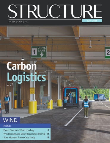
Carbon
Logistics p. 24
WIND INSIDE: Deep Dive Into Wind Loading 8 Wind Design and Mean Recurrence Interval 14 Steel Moment Frame Case Study 18
JULY 2026
SHEAR
STRENGTH When seismic and wind demands push your designs to the limit, Vulcraft and Verco provide the resources to evaluate steel deck and joist systems with precision and efficiency. Our Online Design Tools streamline analysis, helping you design with confidence under pressure. From diaphragm to wall anchorage design, our tools help evaluate deck, joists, connections, and other structural elements to ensure reliable performance under lateral forces. And when your project calls for something uniquely challenging, our design professionals help translate complex details into buildable solutions.
EXPLORE VULCRAFT.COM
EXPLORE VERCODECK.COM
ADVERTISER index
Please support these advertisers
Anthony Canfor.................................................................. 9 ASC Steel Deck................................................................. 4 LAVA..................................................................................... 3 Computers & Structures Inc...................................................... Back Cover ENERCALC......................................................................... 7 IES.......................................................................................... 12 NCSEE................................................................................. Inside Back Cover Nucor Vulcraft.................................................................... Inside Front Cover
STRUCTURE
®
CIRCULATION
subscriptions@structuremag.org
EDITORIAL BOARD Chair John A. Dal Pino, S.E. Claremont Engineers Inc., Oakland, CA chair@STRUCTUREmag.org Kevin Adamson, PE Structural Focus, Gardena, CA Marshall Carman, PE, SE Schaefer, Cincinnati, Ohio Erin Conaway, PE AISC, Littleton, CO Sarah Evans, PE Walter P Moore, Houston, TX
July 2026 Digital Issue Available Only at
STRUCTUREmag.org
Steven Judd Interstate Brick, West Jordan, Utah, and H.C. Muddox, Sacramento, California Linda M. Kaplan, PE Pennoni, Pittsburgh, PA Jessica Mandrick, PE, SE, LEED AP Gilsanz Murray Steficek, LLP, New York, NY Brian W. Miller Cast Connex Corporation, Davis, CA Evans Mountzouris, PE Retired, Milford, CT Kenneth Ogorzalek, PE, SE KPFF Consulting Engineers, San Francisco, CA (WI) John “Buddy” Showalter, PE International Code Council, Washington, DC Eytan Solomon, PE, LEED AP TYLin, New York, NY
Publication of any article, image, or advertisement in STRUCTURE® magazine does not constitute endorsement by NCSEA, CASE, SEI, the Publisher, or the Editorial Board. Authors, contributors, and advertisers retain sole responsibility for the content of their submissions. STRUCTURE magazine is not a peer-reviewed publication. Readers are encouraged to do their due diligence through personal research on topics.
EDITORIAL STAFF Executive Editor Alfred Spada aspada@ncsea.com
Managing Editor Shannon Wetzel swetzel@structuremag.org
ADVERTISEMENT–For Advertiser Information, visit STRUCTUREmag.org
10 hours → 2 hours Wood Design Software for wood buildings up to 6 stories.
MARKETING & ADVERTISING SALES Senior Director for Business Development & Marketing Monica Shripka Tel: 773-974-6561 monica.shripka@STRUCTUREmag.org
Sales Manager Audrey Schmook Tel: 312-649-4600 Ext. 213 aschmook@ncsea.com STRUCTURE magazine (ISSN 1536 4283) is published monthly by The ®
Start your free 30-day trial lavabuild.com
National Council of Structural Engineers Associations (a nonprofit Association), 20 N. Wacker Drive, Suite 750, Chicago, IL 60606 312.649.4600. Periodical postage paid at Chicago, Il, and at additional mailing offices. STRUCTURE magazine, Volume 33, Number 7, © 2026 by The National Council of Structural Engineers Associations, all rights reserved. Subscription services, back issues and subscription information tel: 312-649-4600, or write to STRUCTURE magazine Circulation, 20 N. Wacker Drive, Suite 750, Chicago, IL 60606.The publication is distributed to members of The National Council of Structural Engineers Associations through a resolution to its bylaws, and to members of CASE and SEI paid by each organization as nominal price subscription for its members as a benefit of their membership. Yearly Subscription in USA $75; $40 For Students; Canada $90; $60 for Canadian Students; Foreign $135, $90 for foreign students. Editorial Office: Send editorial mail to: STRUCTURE magazine, Attn: Editorial, 20 N. Wacker Drive, Suite 750, Chicago, IL 60606. POSTMASTER: Send Address changes to STRUCTURE magazine, 20 N. Wacker Drive, Suite 750, Chicago, IL 60606. STRUCTURE is a registered trademark of the National Council of Structural Engineers Associations (NCSEA). Articles may not be reproduced in whole or in part without the written permission of the publisher.
JULY 2026
3
J U LY 2 0 26
®
DELTAGRIP DG4
TM
ADVERTISEMENT–For Advertiser Information, visit STRUCTUREmag.org
The Better Way of Connecting Steel Roof Deck at Sidelaps
Contents
F E A T U R E S
CARBON LOGISTICS
By Jessica Westermeyer, PE, SE
Amazon’s DII5 delivery station and logistics facility is a breakthrough in industrial mass timber construction.
Patent Number: 11,872,644
24
z Lightest Pneumatic Sidelap Tool z Increased Connection Strength z Improved Connection Stiffness z Enhanced Crimping Force z Upgraded Durability z Faster Cycle Time
30
ASSESSING STRUCTURAL EMBODIED CARBON
By Ethan Fogle, PE, and Jay Arehart, Ph.D
A new prestandard provides a standardized path for carbon assessments..
In Every Issue ascsd.com/deltagrip-dg4
4
STRUCTUREmagazine
3 Advertiser Index 39 SE News 42 CASE in Point 44 SEI Update 46 NCSEA News
37
C O L U M N S a n d D E PA RT M E N TS
6 Editorial
37 In Focus
Are You Ready When the Call Comes?
Democratizing the Future: Why Technology Adoption Is Everyone’s Job
By CASE Coalition
By Brian Petruzzi, PE
8 Structural Design
48 Codes and Standards FAQ on SEI Standards
A Deep Dive into Wind Loading on Roof-Mounted Screen Walls
By Jeannette Torrents, PE, SE
By Todd Clapp and John O’Brien, NCSEA Wind Committee
14
49
Structural Design
Lost in Load Factors? Navigating Wind Design with Mean Recurrence Interval
Structural Forum
AI Use in Structural Engineering Practice, and the Preservation of Engineering Judgment By David O. Prevatt, Ph.D, PE
By Pengcheng ‘Alex’ Zhou, PE and James Fong, EIT
18
18 Structural Design
Design for Speed & Resiliency
22
By Matthew Bosch-Willett and Nathan Canney
22 Structural Design
Beyond the Bunker: Integrating Blast Resistance into Everyday Structures By Pritish Dey Sarkar
33
Structural Forum
Clarifying Engineer of Record and Insurance Consultant Responsibilities By Steven G. Provenghi, SE, FASCE
33
35 Codes and Standards
Structural Building Codes and Standards Developers Respond to Champlain Towers South Collapse By Jim Foreman, Ben Estrich, and Nicole Lane
35
JULY 2026
5
EDITORIAL Democratizing the Future: Why Technology Adoption Is Everyone’s Job By Brian Petruzzi, PE
M
y father-in-law is scared of two things: needles and spiders. So, on his 40th birthday, he got a tattoo of a spider, confronting both fears in a single, permanent act of defiance. It’s the only tattoo he has, and the story has stuck with me for years. I have always found his directness in dealing with fear and uncertainty refreshing. Identifying the thing that makes you uncomfortable and addressing it head-on is powerful. As I step into the role of NCSEA President, I believe our profession needs to adopt the same approach with technology. The uncertainty surrounding artificial intelligence—its potential, its limitations, and its implications for structural engineering—has created a collective unease across our industry. We can either let that discomfort paralyze us, or we can confront it directly. When we talk about AI in structural engineering, the conversation inevitably drifts towards concerns with licensing, life safety, and engineering judgement. We read about massive technology companies or large engineering firms developing custom generative design tools. This creates unease and a pervasive narrative that innovation is the exclusive domain of the Goliaths of our industry—those who possess the capital, personnel, and data infrastructure to push the boundaries of what is possible. But I believe we are looking at the technology equation backward. The structural engineering profession is predominantly made up of small to medium-sized firms. The highest return on investment for our industry will not come from a handful of large firms building bespoke tools that only they can use. Instead, the true transformation will occur when we democratize technology—when we create the forums, processes, and workflows that allow every structural engineer, regardless of firm size or resources, to consume and integrate these advancements into their daily practice.
The Innovation Gap The challenge we face is not a lack of technology; it is a lack of adoption. The tools exist, but the vision and road map for how to implement them broadly across the profession do not. For small to mid-sized firms, the barrier to entry often feels insurmountable. How does a 20-person firm find the time to evaluate AI tools while meeting project deadlines? How do we shift our firm cultures to 6 STRUCTURE magazine
True transformation will occur when we democratize technology—when we create the forums, processes, and workflows that allow every structural engineer, regardless of firm size or resources, to consume and integrate these advancements into their daily practice. embrace new workflows without losing the core engineering judgment that defines our value? This is the innovation gap—the space between the creation of a new technology and its widespread, practical application. Bridging this gap is a collective responsibility of our professional organizations.
The NCSEA Innovation Council To meet this critical need, the NCSEA Innovation Council was launched earlier this year to ensure all firms have the resources to navigate this transition. The Innovation Council is built on the belief that technology adoption must be a collaborative, community-driven effort. It is organized around five core themes: • Collaboration: NCSEA Forj Platform. • Education: Webinars, AI Certificate Programs, and Hackathons. • Partnerships: Academic, Software, and Organizational. • Ethics and Standards: NCSEA AI Policy Template. • Thought Leadership: White Papers, Case Studies, and Best Practices. Our initial focus is centered on AI and coding, with project teams already working on initiatives like “Coding for Structural Engineers” and our first ever hackathon. The Big Build: SE Hackathon is being organized on October 27 in collaboration with AEC Tech, one day prior to this year’s NCSEA Summit in San Francisco. The Big Build will focus on vibe-coding and is designed for structural engineers of all experience levels. Whether you’ve never
written a line of code or you’re a seasoned developer, you’ll find your place here.
A Call to the Community At a recent NCSEA Leadership Week—where we bring together 100+ structural engineering leaders for 72 hours of dialogue—someone approached me after a presentation and said “It’s clear you are an AI believer, and I am not an AI believer.” I have thought a lot about this framing, and I think it misses the point. I don’t know the future of AI, or how it will impact me personally or the profession more broadly. However, I am a believer in progress and the continual reinvention of myself and the people around me. I don’t know how to code. I don’t understand the full potential of digital twins or robotics. I am overwhelmed by the narrative around AI. But I decided that I can either stay passive and react, or be proactive and take control of the narrative as much as possible. For these reasons, NCSEA is creating forums where interested individuals can collaborate on all things innovation, so that as a profession we can organize around what we want the future to look like. This is where I challenge each of you: get outside your comfort zone. Set aside dedicated time to tinker with AI tools. Typically, leadership delegates tasks to their team to execute, but in this moment of technological shift, everyone—from the newest graduate to the senior principal— should be learning and experimenting. Encourage reverse mentorship, where the younger generation mentors the older generation on what is possible. This is a powerful way to foster inclusion, finding places for individuals interested in coding and automation to drive strategic value for firms that have historically only valued traditional structural engineering skill sets. Whether you are AI-curious or leading innovation efforts at your firm, the Innovation Council needs your voice. Join the 300+ individuals already on the Forj Community Platform today and help us democratize the tools that will shape the future of structural engineering. Our communities—and our profession—will be better for it. ■ Brian Petruzzi, PE, is the current President of NCSEA. He is passionate about supporting people, building community, and creating forums where diversity of thought is able to thrive.
structural DESIGN A Deep Dive into Wind Loading on Roof-Mounted Screen Walls Practicing engineers can use the suggestions in this article as a guide when designing buildings with screen walls. By Todd Clapp and John O’Brien, NCSEA Wind Committee
M
any practicing engineers (the authors included) have attempted to determine wind pressures on roof mounted screen walls and have wondered which provisions of the American Society of Civil Engineer’s Minimum Design Loads and Associated Criteria for Buildings and Other Structures (ASCE 7-22) should be used and whether they estimate wind pressures accurately. Wind pressures on these elements can be seemingly difficult to determine with any degree of accuracy and several code provisions within ASCE 7 may appear to provide conflicting information. Screen walls are walls that project vertically from a roof structure, whose purpose is often to conceal mechanical, electrical, or plumbing (MEP) equipment from view. They can be in any configuration or geometry, and they do not have a roof over them. They generally are used for aesthetic reasons and are not a part of the primary building structure. The requirements for screen walls are almost always driven by architectural design. Parapets may also serve as screen walls, or screen walls may be parapets. The International Building Code (IBC) defines a parapet as “the part of any wall entirely above the roof line;” while in the context of wind engineering we often assume it is a continuation of the exterior wall above the roofline. For this article, rooftop units (RTUs) are defined as mechanical or building HVAC equipment supported by a building roof structure.
Fig. 1. The mechanics of wind flow over a flat roof is illustrated in this building elevation.
Wind Flow Over a Building Figure 1 shows the mechanics of wind flow over a building with a flat roof without screen walls. When the wind flows up and over the building, it separates from the roof surface near the windward edge and creates separation vortices. Wind pressures in this zone are generally characterized with high uplift (suction). ASCE 7 provides a method to calculate the width of this zone as a function of the building height and width, called the “Width of pressure coefficient zone” represented by the symbol ‘a’. After a distance of ‘a’, this turbulent flow re-attaches to the flat roof and reloads a vertical surface with a windward pressure. Figure 2 shows the mechanics of wind flow over a flat roof with screen walls/parapets at both edges of the building. The windward screen wall/parapet is designed for the windward wall pressures on the front face and roof uplift pressures on the interior face. The leeward wall is designed for leeward wall pressures on the exterior face and windward wall pressures on the interior face. Figure 3 shows the local effects of wind flow on screen walls with wind flowing above and below the wall. Design wind pressures on screen walls will vary greatly, depending on the wind direction and their location on the roof. How practicing engineers can account for this variability is addressed later in this article. 8 STRUCTURE magazine
Fig. 2. The mechanics of wind flow over a flat roof with screen walls at roof edges is illustrated here.
Fig. 3. This screen wall section shows wind flow above and below a wall.
BUILD TALL WITH POWER COLUMN ®
TOMORROW’S ENGINEERED WOOD - TODAY! POWER COLUMN® FEATURES • Sustainable Forestry Initiative (SFI®) Certified • Manufactured with superior strength southern yellow pine MSR Lumber • Available in range of appearance grades for structural and architectural applications • Superior alternative for Tall Wall applications • Load path solution for Engineered Beam and Header Products • Framing members such as Power Beam® can easily be attached to Power Column® with simple connection detailing Anthony Forest Products is part of the Canfor Group of Companies CA N FO R . CO M
|
800.221. B E A M
|
A N T H O N Y FO R E S T. C O M
Anthony Forest Products Company, LLC
©
Calculating Pressures Applied to Screen Walls The ASCE 7 standard is a valuable tool for estimating wind pressures on a variety of building and non-building structures. However, the standard does not specify which provisions should be used to calculate wind pressures on screen walls. Additional confusion may arise when deciding whether main wind force resisting system (MWFRS) or components and cladding (C&C) pressures should be used, and how they are calculated. C&C wind pressures should be used for the design of all screen wall elements, roof supports, and connections. MWFRS pressures should be used for calculating wind story forces, base shears, and overturning moments used for the design of the lateral force-resisting system and foundations. Estimating design forces for rooftop equipment is often challenging during the early design phases because the locations, sizes, and layout of these elements may not be finalized yet. In this case, the engineer must apply judgement to make conservative estimates of locations and heights. Neglecting wind effects on these elements early in design can cause unconservative designs, leading to re-work or conflicts with architectural or MEP elements later in the design process. The authors have heard of engineers using a variety of ASCE 7 methods to calculate MWFRS and C&C pressures applied to screen walls. These include the following, but in the authors’ opinion, not all of these are correct: 1. Chapter 27, Wind Loads on Buildings: Main Wind Force Resisting System (Directional Procedure): The wall and roof pressure coefficients provided by the directional procedure were originally developed from wind tunnel tests for regular shaped buildings as a
function of wind direction. These are average pressures, intended to be used for the design of the building lateral force-resisting system. The building models tested during the development of these coefficients did not include screen walls. Section 27.3.4, Parapets, provides net pressure coefficients to account for the wind pressures on parapets. Generally speaking, using wall and roof pressures from this method to account for screen walls is not appropriate. However, parapet pressures determined from this section could be used for screen walls located near the building edge as described later in this article but may be conservative for screen walls located away from the building edge. 2. Chapter 28, Wind Loads on Buildings: Main Wind Force Resisting System (Envelope Procedure): Wall and roof pressure coefficients provided by the envelope procedure are described in the commentary as “pseudo-pressures,” which were developed through rigorous wind-tunnel testing and analysis for the building configurations described in the scope of the chapter. Similar to the Chapter 27 Directional Procedure, the research leading to these coefficients did not include screen walls, and using pressures from this method is not appropriate except where parapet pressures may be used near building edges as described later in this article. 3. Chapter 29, Solid Freestanding Walls and Solid Signs: The wind tunnel testing for walls and signs originated from studies for “plate-like” structures on ground (e.g. fences or walls). The provisions were later expanded based on additional testing of plate-like structures elevated on isolated supports (i.e. signs). While the pressure coefficients associated with this method account for the shape effects of wind interaction with screen walls, the underlying research does not consider that a freestanding wall is located on top of a building. The pressure coefficients may not accurately capture
Frequently Asked Questions Can shielding be considered when designing screen walls or RTUs in close proximity? It can seem intuitive that if a RTU is located behind a screen wall, penthouse, or another large RTU that wind loads might be lower. However, ASCE 7 does not currently allow any reduction in wind pressure due to shielding by other structures or by topographic features because of the “lack of reliable analytical procedures for predicting the effects of shielding.” However, this does not preclude the determination of shielding effects and the corresponding reductions in velocity pressure by means of wind tunnel testing. Research has shown that in certain conditions, an object upwind of another structure can create an effect called dynamic interference, which can cause increased wind pressures on the downwind object. In reality, structures have failed when a new structure was placed upwind. These are rare occurrences but should cause some pause when an engineer automatically assumes an upwind element shields a downwind element. The most recent relevant research for wind loads on mechanical units shielded by screen walls (Morrison and Miller, 2017) was based on wind tunnel testing of 4-foot tall screen walls. The following is a short list of relevant findings from this report: • If the RTU height is above the top of screen wall, then wind loads were not reduced. • RTUs within fully enclosed screen wall configurations observed wind loads that were between 45%-60% less than 10 STRUCTURE magazine
calculated using ASCE 7-10. • RTUs within partially enclosed screen wall configurations did not see reduced wind loads; however, wind loads were increased in some cases. • The presence of mechanical equipment behind the screen wall did not reduce the loading on the screen wall. If a very large obstruction is in front of a mechanical unit, in theory, uplift loads on the unit will be increased and horizontal loads will be decreased. The roof wind uplift coefficients shown in Figure A indicate that air flow reattachment occurs at about 2*h downwind from the edge of a roof, where ‘h’ is the mean roof height of
Fig. A. Wind flow over roof.
the wind flow effects exhibited as the wind flows over a building roof as discussed previously. 4. Chapter 29, Rooftop Structures and Equipment for Buildings (MWFRS): The research used in the development of these provisions included wind tunnel testing for roof mounted cubes, but did not consider wind pressures on, or the influence from screen walls. This method should be used to determine MWFRS pressures for rooftop equipment. The commentary to Section 29.4.1, Rooftop Structures and Equipment for Buildings, states that in the absence of other data, wind pressures on screen walls should use pressures determined from the rooftop structures and equipment provisions. ASCE 7-22 does not provide detailed C&C provisions based on the effective wind area of RTU elements. Section 30.8, Rooftop Structures and Equipment for Buildings, addresses C&C loads by directing the engineer to distribute the force calculated from Chapter 29 over the area of the RTU cladding element being considered. Recent research from Factory Mutual (FM) Global and University of Western Ontario provides guidance for rooftop equipment C&C and additional MWFRS considerations. This is currently working through the ASCE 7-28 balloting process. 5. Chapter 30, Wind Loads: Components and Cladding for Roofs and Walls: The roof and wall pressures in this chapter are derived from a wind tunnel testing process for bluff bodies (buildings), similar to the Directional Procedure described previously. The use of the directional procedure roof and wall pressure coefficients for roof mounted equipment or screen walls is not appropriate. 6. Chapter 30, Wind Loads: Components and Cladding for Parapets: Parapet pressures in Section 30.6, Parapets, describe the wind actions on individual surfaces of windward and leeward parapets, Cases A & B, respectively. Wind tunnel research has confirmed
the load cases reasonably represent the peak pressures developed on cladding at each face of a parapet. However, the research indicates that the peak pressures on each face do not occur simultaneously. Combining the pressures described by each load case into a net pressure for the design of a parapet element receiving wind load on each face (a parapet framed using cantilevered wall studs, for example) is likely conservative, but additional guidance is not contained in ASCE 7. The use of parapet pressures is appropriate for screen walls located at a building edge but may be conservative for screen walls located away from the building edge. The use of parapet pressures is not appropriate for rooftop equipment. 7. Chapter 31, Wind Tunnel Procedure: The wind tunnel procedure performed in accordance with Chapter 31 is the most accurate method of determining wind loads on screen walls. Computational Fluid Dynamics (CFD) could also be used in conjunction with wind tunnel testing as described by Chapter 31. (CFD is a tool that uses numerical analysis and algorithms to simulate, analyze and solve problems involving liquid and gas flows.) In many, but not all cases, wind pressures will be less than calculated using the ASCE 7 provisions when this method is used. The challenge with this method is that the design team must convince the project stakeholders that the benefits of performing a wind tunnel test will outweigh the upfront costs and lead time. In order to demonstrate the wide range of external pressure coefficients (Cp/GCp) that can be obtained using the methods above, the maximum and minimum coefficients for each method are listed in Table 1. Possible coefficients range from 0.6 to 5.5. Parapet coefficients tend to be the highest, and MWFRS wall coefficients tend to be the lowest. The Chapter 29 rooftop structures provisions provide
the building. Therefore, it may be reasonable to assume that if the height of obstruction = ‘h’, then the wind is turbulent (i.e., not able to reload a vertical surface) for 2*h down wind. Some theory supports the reduction of MWFRS for shielded RTUs downwind, but the research does not support any reduction in C&C wind loads.
ment to an existing building can create a wind sail effect that increases MWFRS and C&C loads. The increase in lateral load and overturning needs to be checked in accordance with the International Existing Building Code (IEBC). It can be beneficial to perform a wind tunnel test for existing building renovation projects that include new rooftop structures in order to possibly reduce wind pressures on these new elements and account for any shielding that may be present as mentioned previously. This may help minimize costly strengthening of existing building elements and the existing lateral system.
Can wind loading on screen walls be reduced for louvered or perforated panels? Wind pressures on perforated screen walls depend upon the screen wall geometry, the size/spacing of the perforations, and the wind speed. ASCE 7 commentary C29.4.1 states that in the absence of appropriate wind tunnel testing, the full wind load should be applied to porous screen walls. Wind flow takes the path of least resistance. At low wind speeds, wind may be able to easily pass through louvers and perforations. However, at design wind speeds the wind flow through the panel becomes constricted and the wind is more likely to flow around the full width/height of the wall, resulting in pressures similar to a solid panel. Recent research (Morrison and Miller, 2017) concluded that screen wall type/porosity did not significantly change wind loads. Do increased wind pressures on existing building elements need to be considered when adding a roof top structure to an existing building? Extending parapets or adding roof top screen walls and equip-
What Risk Category should be used for determining the basic wind speed for screen walls and RTUs? The Risk Category used for the design of screen walls and RTUs should not be less than the Risk Category of the building that they are connected to. This is intuitive for RTUs because they are required for the building to function properly. Likewise, a screen wall blowing off of a building’s roof could damage other parts of the building or cause an obstruction that restricts the intended function of the building. Additionally, if the equipment provides necessary service to another building, the Risk Category should also consider the building being served. In some cases, the equipment may be designed for a higher risk category than the building supporting it. Additional guidance can be found in the ASCE 7 Chapter 29 commentary.
JULY 2026
11
Table 1. Absolute Values of ASCE 7-22 External Pressure Coefficients (Cp/GCp) MWFRS-Parapets (ASCE 7-22: Ch. 27)
Solid Freestanding Walls (ASCE 7-22: 29.3)
Rooftop Structure Provisions (ASCE 7-22: 29.4.1)
C&C-Walls* (ASCE 7-22: Ch. 30)
C&C-Parapets* (ASCE 7-22: Ch. 30)
Max
1.5
4.3
1.9
1.8
5.6
Min
1.0
0.6
1.0
0.6
1.3
*C&C loads assume an effective wind area of 10 square feet
Table 2 (Part 1). Wind Design Parameters at Example Buildings Screen Wall Location
Basic Wind Speed, V (mph)
Exposure Category
Screen Wall Height Above Ground (ft)
Wind Pressure Zone
Building 1 - High Roof
120
C
97
Edge
Building 2 - Low Roof
170
C
55
Interior
Building 2 - High Roof
170
C
114
Edge
Building 3 - High Roof
115
B
202
Edge
Building 3 - High Roof
115
B
202
Interior
a fairly tight and central range of coefficients between 1.0 and 1.9. ASCE 7 requires using the rooftop structures provisions of Chapter 29 to calculate wind pressures on roof mounted mechanical equipment for both MWFRS and C&C loads. However, the ASCE 7 standard does not have specific language addressing screen walls. While the commentary Section C29.4.1 offers valuable recommendations, it is not enforceable code, and building officials or peer reviewers may reasonably question the design approach. However, this is the best currently available approximation in ASCE 7, and this is the method that should be used if a wind tunnel procedure is not performed. This approach can be conservative for buildings that have screen walls on lower roofs of buildings because it is based on the mean roof height of the overall building and not the height of the screen wall itself. The Chapter 29 rooftop structures procedure does not consider the location of the rooftop structure on the roof but instead provides a
single pressure regardless of location which can be unconservative for screen walls located near the edge of a roof. The ASCE 7 commentary to Section 29.4.1 states that screen walls located close to a building edge should be designed for parapet pressures. However, it does not provide a method for determining the proximity to the roof edge where roof top equipment pressures stop and parapet pressures begin. The authors believe, based on our understanding of the research that is the basis for ASCE 7, that it is reasonable to design screen walls located in edge or corner roof zones for parapet pressures and screen walls located in interior roof zones for Chapter 29 rooftop structures and equipment pressures. When calculating MWFRS pressures on screen walls that are in edge or corner roof zones, the wind pressures should be calculated per both Chapter 27 parapet provisions and Chapter 29 rooftop structures provisions and the largest of the two calculated pressures should be used for design.
ADVERTISEMENT–For Advertiser Information, visit STRUCTUREmag.org
Get 15% off with STR2026 iesweb.com/str
Real-World Examples
I E S
Proven
structural software for over 30 years
Flexible
licensing to meet your needs
Reliable
support from professional engineers
12 STRUCTURE magazine
In order to better understand the variability of the pressures that can be obtained from the different methods in ASCE 7 and how they compare with wind tunnel testing, three real world examples of mid-rise buildings with roof mounted screen walls are explored here. A reputable wind engineering consultant performed the wind tunnel testing for each example. See Table 2 for external pressure coefficients and corresponding design wind pressures for each screen wall as determined by different methods from ASCE 7 and wind tunnel testing. The recommended procedures and coefficients are shown in the table notes. Some of the procedures in Table 2 are not recommended but values are provided for the sake of comparison. This data shows the significant variability of the pressures obtained using each different procedure.
Table 2 (Part 2). Absolute Values of Screen Wall Coefficients and Wind Pressures at Example Buildings Screen Wall Location
MWFRSDesign Parapets Pressure (ASCE 7-22: (psf) Ch. 27) Cp
Solid Design Freestanding Pressure Walls (ASCE (psf) 7-22: 29.3) Cf
Rooftop Structures (ASCE 7-22: 29.4.1) GCr
Design Pressure (psf)
C&CWalls (ASCE 7-22: Ch. 30) GCp3
Design Pressure (psf)
C&CParapets (ASCE 7-22: Ch. 30) GCp3
Design C&C-Wind Pressure Tunnel Testing (psf) Design Pressure (psf)4
Building 1 High Roof
1.5
61
1.9
56
1.9 1
77
0.9
44
2.5 2
123
50
Building 2 Low Roof
1.5
86
1.9
93
1.9 1, 2
129
0.9
73
2.8
210
55
Building 2 High Roof
1.5
102
1.9
104.7
1.9 1
129
0.9
73
2.9 2
218
85
Building 3 High Roof
1.5
42
1.9
44
1.9 1
53
0.9
30
2.7 2
90
67
Building 3 High Roof
1.5
42
1.9
44
1.9 1, 2
53
0.9
30
2.7
90
67
Table 2 Notes: 1. This is the recommended ASCE 7 procedure and coefficient for calculating MWFRS pressure acting on this screen wall. 2.This is the recommended ASCE 7 procedure and coefficient for calculating C&C pressure acting on this screen wall. 3.C&C loads assume an effective wind area of 10 square feet. 4.The pressures listed are specific to the site and building geometry on which the wind tunnel testing was based. It is not appropriate to draw conclusions from these pressures for any structures other than the building and site for which they were originally intended.
The ASCE 7 recommended C&C procedure produced higher wind pressures when compared with wind tunnel testing in every case except for at the Building 3 interior condition. Building 3 happened to be the only building that was classified as Exposure Category B. If it had been classified as Exposure Category C, then the wind pressures would have been in better agreement. This highlights the critical role of surface roughness and exposure category in the calculation of accurate wind pressures. The C&C parapet pressures from Chapter 30 yielded high pressures in all cases when compared with wind tunnel testing. The remaining methods yielded varying results that were sometimes higher and sometimes lower than the wind tunnel testing. This information represents only a small sample of buildings and is not intended to be comprehensive. Any conclusions drawn from this information should be corroborated with the code and the literature.
Conclusion ASCE 7-22 does not currently provide specific code provisions for calculating wind pressures on screen walls. Wind tunnel testing or CFD performed by a wind engineering consultant will provide the most accurate and least conservative wind pressures for design. If those methods are not possible, the best available procedure for screen walls that are not located close to a roof edge is the Chapter 29 provisions for rooftop structures for MWFRS and C&C. The best available procedure for screen walls that are located close to a roof edge is the Chapter 30 parapet procedure for C&C. For MWFRS pressures on screen walls close to roof edges we recommend using either the Chapter 29 provisions for rooftop structures or the Chapter 27 parapet provisions for MWFRS, whichever results in the largest pressures.
Additional research and wind tunnel testing is needed to develop a wholistic method for calculating wind pressures on common configurations. The following is a list of enhancements to the existing method that should be considered. • Consider location of the roof top structure relative to the edges of the building. • Provide better agreement with wind tunnel testing and CFD. • Account for shielding from adjacent elements. • Account for perforations of various sizes and geometry for the screen wall. • Separately consider the effects of tornadoes or hurricanes on roof op structures where appropriate. Research can take a long time to be funded, completed, and incorporated into ASCE 7. In the meantime, practicing engineers can use the suggestions in this article as a guide to make educated decisions and use proper engineering judgement when designing buildings with screen walls. ■ Full references are included in the online version of the article at STRUCTUREmag.org.
Todd Clapp, PE, SE, is a Senior Project Engineer at Martin/Martin Consulting Engineers and a member of the NCSEA Wind Committee. John O’Brien, PE, SE, is a Senior Associate and Director of Structural Engineering at PES Structural Engineers. He serves as Chair of the NCSEA Wind Committee and Chair of the ASCE 7 Chapter 29 Task Committee for Wind Loads on Building Appurtenances and Other Structures.
JULY 2026
13
structural DESIGN Lost in Load Factors? Navigating Wind Design with Mean Recurrence Interval
Concepts such as mean recurrence interval offer a useful framework for interpreting wind design intent, even as code formats and load combinations change over time. By Pengcheng ‘Alex’ Zhou, PE and James Fong, EIT
W
ind design provisions across codes and standards, including ASCE 7 Minimum Design Loads and Associated Criteria for Buildings and Other Structures (2005 through 2022), ASCE 37 Design Loads on Structures During Construction, and Factory Mutual (FM), often appear inconsistent due to differing wind load factors used in load combinations. Focusing solely on these factors can obscure an unchanging design principle: the target wind design is governed by the mean recurrence interval (MRI), which remains consistent even as code formats and load factors evolve. Rather than getting “lost in load factors,” engineers can use MRI as a compass to interpret wind design provisions and communicate design intent more clearly with architects, contractors, and design-assist partners.
This probabilistic framework reflects the reliability objectives embedded in ASCE 7. Buildings with greater consequences of failure (Risk Categories III and IV) are assigned higher MRIs (1,700 and 3,000 years, respectively), resulting in lower probabilities of exceedance.
Basic Wind Speed Design wind pressure begins with the basic wind speed, obtained from the wind maps in ASCE 7 or the online ASCE Hazard Tool based on project location. The basic wind speed is a three-second gust speed at 33 feet above ground in Exposure C terrain, such as airports and similar open country exposures. These wind speeds are derived from statistical analysis of historical meteorological data from more than 500 stations, each with at least 15 years of record, and correspond to specific MRI depending on the building risk category.
Probability and Mean Recurrence Interval The design wind speed for different risk categories of buildings corresponds to the MRI of the wind hazard. For example, the ultimate design wind speed corresponding to risk category II buildings represents a 700-year MRI wind event. A common misconception is that a 700-year event occurs once every 700 years. In reality, the term corresponds to an annual probability of exceedance, Pa, of about 0.14% (Pa ≈ 1/700). The probability of experiencing at least one such event during the lifespan of the building varies with the targeted risk category. For example, over a 50-year building lifespan, a 700-year wind event has roughly a 7% chance of being exceeded (Fig. 1). P=1-(1-Pa)50=6.90% 14 STRUCTURE magazine
Fig. 1. Probability of exceedance for a 700-year MRI wind event.
Connecting Basic Wind Speed and Load Factors In general, design wind pressure, W T, in codes can be expressed in a simplified form as: W T=CF(V)2WLF Where, CF is a generic coefficient that accounts for factors such as building geometry, height, air density and terrain as defined in ASCE 7 and WLF is the wind load factor. Because wind pressure is proportional to the square of the basic wind speed, V, velocity is the primary driver for calculating wind pressure.
Previously in ASCE 7-05 In ASCE 7-05 and prior, the basic wind speed was provided in a single wind speed map based on a service level, 50-year MRI wind speed, V50. Wind pressure calculations included an importance factor, I, and a load combination factor of 1.6 to amplify this wind speed to appropriate ultimate design wind loads based on risk category: W T=CF(V50)21.6I
For example, I for a risk category II and III building was 1.0 and 1.15, respectively. To understand how these factors connect to MRI, Peterka and Shahid (1998) conducted research to establish a relationship between MRI, T representing time in years, and the ratio of wind speed for any return period, V T, relative to V50. They developed the following equation after analyzing long-term wind speed data for non-hurricane zones:
Solving for T, this relationship can be expressed as: T=0.00228e10 . As an example, ASCE 7’s target MRI for a risk category III building is 1,700 years. Solving this equation with T as 1,700 results in a WLF of 1.83, which is equivalent to the 1.6 load factor multiplied by the 1.15 importance factor from ASCE 7-05.
Changing Load Factors, Constant MRI – ASCE 7-10 to Present (ASCE 7-22) One disadvantage with ASCE 7-05 was that amplifying service level wind loads to reach ultimate level MRI targets was not consistent with the procedure for other hazards, particularly seismic loads. To address this, ASCE 7-10 transitioned away from the single wind speed map and introduced separate maps based on each risk category’s target MRI. Since the updated maps provided the ultimate level basic wind speed, the importance factor was removed and WLF reduced to 1.0. However, the target MRI for each risk category remained the same. The wind pressure calculation was simplified as: W T=CF(V T )21.0 For a risk category III building in ASCE 7-10, V T=V1700, which is read directly from the 1,700-year MRI wind map. This applies regardless of whether a building is in a hurricane or non-hurricane prone region as the maps incorporate hurricane wind speed data. ASCE 7 versions since 7-10 have maintained this framework, with slight revisions to the basic wind speed values as new wind data analysis became available. ASCE 7-22 also introduced wind speed maps for tornado zones which follow a similar logic to the previous chapters.
Factory Mutual Insurance Company (FM Global) If building owners choose to pursue FM insurance, certain building assemblies must be designed to meet FM’s load criteria. FM believes that property losses can be mitigated by identifying hazards using an engineered approach like ASCE 7. Table 1. Comparison of a Risk Category III Building Reference
Ultimate Wind Load Factor
Basic Wind Speed Map
Importance Factor
Target Ultimate Design Wind MRI
ASCE 7-05
1.6
50-year MRI
1.15
1,700
ASCE 7-10 to 7-22
1.0
1,700-year MRI
N/A
1,700
FM
2.0
50-year MRI
1.15
8,800
Fig. 2. MRI versus wind load factors using the Peterka and Shahid (1998) relationship.
FM’s procedure is like ASCE 7-05 in that the basic wind speeds are typically based on a 50-year MRI wind speed map. The ultimate design wind load pressure calculation includes an I of 1.15 and a safety factor of 2.0, written as: W T=CF(V50)2(1.15)(2.0) Unlike ASCE 7-05, FM assigns a uniform 1.15 importance factor, making wind pressure determination independent of risk category. The 2.0 safety factor also results in higher pressures compared to ASCE7. Using the Peterka and Shahid (1998) relationship, the equivalent return period for ultimate level FM wind pressures is about 8,800 years (Fig. 2). Recent updates to FM include separate wind speed maps for tornadoes, which follow the 10,000-year MRI maps from ASCE 7-22. Although FM pressures are amplified, FM requirements are only intended to be used for components and cladding elements such as roof assemblies, roof decks, and the securement of roof decks to structure below. FM pressures do not apply to the design of main wind force resisting system elements such as braces and shear walls. See Table 1 for a comparison of load factors and MRI between ASCE 7-05, ASCE 7-10, and FM.
0.6W and Serviceability The discussion of load factors and target MRI thus far has focused on ultimate level wind loads intended for life-safety design. MRI targets such as 700 years or 1,700 years represent extreme wind events that the structure’s main lateral force-resisting system must be designed to resist. However, these extreme events are not representative of day-today wind behavior. When evaluating serviceability criteria such as frame drift, ASCE 7 and AISC Design Guide 3 Serviceability Design Considerations for Steel Buildings recommend engineers to use a 10- or 25-year MRI wind speed, rather than the 0.6W used for allowable stress design, as the 0.6 factor leads to higher serviceability wind speeds than suggested. For example, using Boston wind data from ASCE 7-22 for a risk category III building, the 1,700-year MRI wind speed is 124 mph, while the 10-year MRI wind speed is approximately 74 mph. The load factor is =0.36 which is significantly less than 0.6 (Table 2). Ultimately, the target MRI wind speed used for drift may require input from the building owner for the target performance goal. For the deflection of individual structural members, the International Building Code (IBC) typically recommends using a 10-year MRI wind speed with a wind load factor as calculated above, or a roughly JULY 2026
15
Table 2. ASCE 7-22 Wind Speeds for a Risk Category III Building in Boston, MA Basic Wind Speed (mph)
Wind Load Factor
Target Wind MRI
74
0.36
10-year
83
0.45
25-year
91
0.54
50-year
98
0.6
100-year
124
1.0
1700-year
equivalent factor of 0.42 (after ASCE 7-05). Member deflections should be limited to the IBC requirements and coordinated with the facade manufacturer based on the selected facade product.
Wind Load During Construction Although it is not adopted by the IBC, ASCE 37 provides guidelines for determining wind loads on structures during construction. Per ASCE 37, buildings during construction shall be considered as risk category II unless otherwise required by the authority having jurisdiction. ASCE 37 provides reduction factors that modify the ASCE 7 basic wind speed based on the anticipated length of the construction period, reflecting the shorter duration of exposure. These factors are calibrated so that the probability of exceedance during the construction period is approximately the same as the probability of exceeding for the permanent structure during 50-year service life.
For example, a Risk Category II building designed for a 700-year MRI has approximately a 7% probability of exceedance over a 50-year service life as discussed before. A theoretical probability match for a 2-to-5-year construction duration would correspond to a wind speed reduction of roughly 0.82: approximately a 70-year MRI wind. ASCE 37 instead specifies a 0.9 reduction factor, which corresponds to a higher effective wind hazard level and therefore provides a conservative margin. Recent discussions for ASCE 37-25 have explored presenting construction wind speeds with equivalent MRI, in addition to the traditional reduction factors.
Conclusion Design standards will continue to evolve as new data and research improves our understanding of wind hazards. Although code formats and load combinations may change over time, concepts such as MRI offer a useful framework for interpreting wind design intent. By focusing on these underlying principles, engineers can better navigate future code developments. ■ Full references are included in the online version of the article at STRUCTUREmag.org. Pengcheng ‘Alex’ Zhou is an Associate at LeMessurier. (pzhou@lemessurier.com). James Fong is a Designer at LeMessurier (jfong@lemessurier.com)
ADVERTISEMENT–For Advertiser Information, visit STRUCTUREmag.org
2026 Structural Engineering Summit The conference the structural engineering community calls home.
October 27-30, 2026 Hilton Union Square San Francisco, California 16 STRUCTURE magazine
Register & Learn more
WWW.STRUCTUREMAG.ORG
FIND IT ALL IN STRUCTURE RESOURCES FOR THE PRACTICING ENGINEER
Article Archives Each new issue of STRUCTURE and its articles are posted to the website, dating back to 2012
Ask Archie, Our New SE GPT Check out our updated AIpowered tool educated on the NCSEA ecosystem, including STRUCTURE’s archives.
Free Webinars Watch a collection of free presentations from STRUCTURE and its partners.
Structural Engineering Resource Guide Find your next industry partner for anchors, foundations, concrete, software, wood products, steel, connections and more.
PLUS READ THE LATEST SE NEWS www.structuremag.org
structural DESIGN Design for Speed & Resiliency
A steel moment frame structure case study merges a modular biaxial steel special moment frame system and a prescriptive damped frame design method. By Matthew Bosch-Willett and Nathan Canney
D
esign in accordance with modern seismic codes is intended to achieve certain performance objectives depending on Risk Category (RC) and hazard severity. For example, a typical RC II structure (e.g., an office building) is expected to achieve life safety performance for the design earthquake (DE) event and collapse prevention at the maximum considered earthquake (MCE) (Table 1). The expectation for the life safety performance is that occupants remain safe during the earthquake but need to evacuate afterwards. In contrast, an RC IV structure (e.g., a hospital) is expected to achieve an Immediate Occupancy performance level at the DE earthquake, meaning that occupants remain safe and the facility retains most operations immediately afterwards. Achieving life safety, however, does not guarantee a community can recover quickly from severe events or return to normal operation. Modern society needs structures that are built quickly and have minimal downtime following a major seismic event. Combining the ConXtech ConXL400 modular biaxial structural steel special moment frame (SMF) system with fluid viscous dampers is one way to achieve this goal.
Table 1. Expected Performance Versus Risk & Ground Motion Severity Risk Category
Ground Motion
Performance Level
RC II
Design
Life Safety
MCE
Collapse Prevention
Design
Immediate Occupancy
MCE
Life Safety
RC IV
Modular Biaxial Steel Special Moment Frame The steel SMF in this study is a chassis-based modular system wherein modularity is implemented at the connections between members. The centerpiece is a wrap-around collar assembly, a one-size-fits-all bolted prequalified SMF connection that joins wide-flange beams to concretefilled composite 16-inch square Hollow Structural Section or built-up box columns. The collar is a biaxial moment connection allowing the same column to participate in orthogonal moment frames (Fig. 1). With collars distributed throughout the floor plate, the system engages more members in the lateral force resisting system (LFRS) than conventional designs, enhancing redundancy.
Dampers Fluid viscous dampers (FVDs) are velocity-dependent energy dissipation devices. FVDs are governed by the constitutive equation F = CVα, where F is the output force, C is the damping constant, V is the velocity, and alpha is the velocity exponent. Forcing a machined piston head through a viscous fluid is how FVDs convert kinetic energy into heat energy, reducing story drifts, accelerations, and yielding in the LFRS. All these benefits lead to more resilient buildings while reducing building material quantities. The Taylor damped moment frame (TDMF) is an ICC-approved alternative LFRS which utilizes SMFs and supplemental damping with FVDs. Developed and validated through the ICC AC494 and FEMA 18 STRUCTURE magazine
Fig. 1. The bolted modular biaxial SMF collar connection allows the same column to participate in orthogonal moment frames.
P-695 procedures, buildings designed in alignment with this procedure meet the code-intended collapse probabilities (i.e., 10% at MCER for RC II) and can be used per ASCE 7-22 Section 12.2.1.1. This prescriptive approach relies solely on modal response spectrum analysis (MRSA) rather than nonlinear analysis per ASCE 7 Chapter 18.
Fig. 3. Shown is the typical frame elevation of the archetype building. The structure is 104 feet tall.
Fig. 2. The archetype 6-story building in the case study has the same rectangular floor plan. Dampers were added to the corners of each floor.
Case Study: 6-Story Building The case study analyzes an archetype 6-story building located near Salt Lake City, Utah. All stories have the same rectangular floor plate with a total building height of 104 feet (Figs. 2-3). The building is in Seismic Design Category D with SDS = 1.062 and SD1 = 1.042. This building was designed in six different ways: RC II, III, and IV, with and without dampers. For the buildings with dampers, dampers were added to the corners on each floor using a single diagonal configuration (Figs. 2 and 4). For the RC III and RC IV designs, additional dampers were added in the lower stories to keep the damper force below a threshold needed for the connection design.
Analysis Procedures ConXtech analyzed the undamped structures using the MRSA procedure in ASCE 7-16 §12.9.1 and the damped structures using the prescriptive procedure in ICC ESR-4769 with the modified displacement amplification factor (Cd = 4½) and reduced base shear scaling. Centerline modeling without rigid end offsets was used to align with ConXtech’s prequalification test results. The low aspect ratio of the concrete-filled floors and roof justified rigid modeling for the diaphragms. With ρ = 1.0 and no torsional irregularities, story drifts were measured at the diaphragm center of mass per ASCE 7-16 §12.8.6.
Design Process ETABS software by Computers & Structures, Inc., was used for frame analysis and AISC 360 design checks, including composite column design with axial and bi-directional bending (PMM) interaction. All SMF beams used RBS cuts modeled explicitly to capture their effect on frame stiffness and to check the reduced section for load combination
Fig. 4. Dampers were added using a single diagonal configuration.
forces. Seismic detailing checks in accordance with AISC 341-16 §E3 and AISC 358-16 Ch. 10 were performed externally.
Initial Frame Design The moment frames in this case study were designed using the Effective Length Method (AISC 360-16 App. 7.2); all scenarios except RC II Damped had B2 < 1.1, permitting K = 1.0 for frame column design. As a highly distributed space frame, seismic axial loads in biaxial columns were below the 20% threshold of ASCE 7-16 §12.5.4; seismic loads were applied independently in the two orthogonal directions. The design initially ignored damper forces on the frames but later included them during final verification. For the Moment Ratio check in AISC 341-16 §E3.4a, the biaxial SMF columns were designed with sufficient strength to force hinging in all SMF beams in both directions simultaneously. Table 2 summarizes the LFRS designs.
Damper Design Damper properties were selected based upon a required 25% viscous damping at the DE level. The velocity exponent was 0.4 for all dampers (mandated by the ICC ESR-4769 procedure) and prescriptive equations were used to determine the damping constant, C. Table 3 summarizes the damper properties and forces for the three damped structures. Due to building symmetry, the dampers were the same in both response directions. JULY 2026
19
Table 2. Frame Design Summary RC II – Undamped
RC II - Damped
RC III – Undamped
RC III – Damped
RC IV – Undamped
RC IV – Damped
SMF Beams (Collar Qty.)
SMF Beams (Collar Qty.)
SMF Beams (Collar Qty.)
SMF Beams (Collar Qty.)
SMF Beams (Collar Qty.)
SMF Beams (Collar Qty.)
Roof
W24 (20)
W21 (16)
W24 (24)
W21 (22)
W24 (32)
W21 (32)
Level6
W24 (20)
W24 (16)
W24 (28)
W24 (22)
W24 (36)
W24 (36)
Level5
W27 (20)
W27 (16)
W27 (28)
W27 (24)
W27 (44)
W27 (40)
Level4
W30 (24)
W27 (20)
W30 (32)
W27 (28)
W30 (50)
W30 (40)
Level3
W30 (24)
W30 (20)
W30 (36)
W30 (28)
W30 (54)
W30 (40)
Level2
W30 (24)
W30 (20)
W30 (36)
W30 (28)
W30 (54)
W30 (40)
Total
132
108
184
152
270
228
Story
Table 3. Damper Designs Per TDMF Design Procedure Story
Risk Category II
Risk Category III
Risk Category IV
Total Quantity
C (k(s/in)0.4)
MCERDamper Force (kips)
Total Quantity
C (k(s/in)0.4)
MCERDamper Force (kips)
Total Quantity
C (k(s/in)0.4)
MCERDamper Force (kips)
Roof
8
53
193
8
61
220
8
81
288
Level6
8
81
267
8
107
351
8
141
453
Level5
8
107
352
8
141
456
8
186
592
Level4
8
141
492
8
162
549
12
162
538
Level3
8
141
492
12
123
421
12
186
623
Level2
8
186
608
12
141
450
16
162
508
Damper Forces on Frames Damper forces were combined with seismic demands per the prescriptive procedure, with 100% of the seismic load and 70% of the damper load (capturing out-of-phase behavior) and vice versa. ConXtech checked the shared DF/SMF beams for P-M interaction on the full beam section. The RBS was checked to ensure sufficient axial capacity to transmit the overstrength damper forces, but as a hinge element it was not deemed necessary to check the RBS for combined seismic and damping forces. For the shared DF/SMF columns, vertical damper forces (modeled as point loads) from each orthogonal frame direction were considered independently for strength checks using load combinations without overstrength on the seismic load effect.
Damper Connections Double gusset plates connect the dampers to the beam-column joints at each end of the dampers; the gussets connect to the damper clevis with pins. Considering the shallow brace angles in most stories and the desire to keep the gusset plate clear of the collar parts, ConXtech opted to connect the gusset plates only to the beam (Fig. 5). Special Case 3 of the Uniform Force Method (AISC Design Guide 29 §4.2.4) provided a suitable model for the load path for the damper forces through the gusset plate and the beam. Collar bolts were checked for combined shear and flexure including moments from the gusset-to-beam interface. Complete-joint-penetration welds connect the gusset plates to 20 STRUCTURE magazine
the SMF beam flange; stiffener plates prevent flange local bending due to the offset between the beam web and the double gusset plates. With a maximum prequalified beam flange width of 10½ inches, the connection detail accommodates a 575-kip damper or smaller.
Moment Ratio Revisited Adding gusset plates increased the RBS “a” dimension beyond the prequalification limits in AISC 358-16. Provided all other design checks are satisfied, this is acceptable because all the inelastic behavior will occur in the “b” dimension. Checking the projected maximum probable moment against the expected plastic moment of the full beam section limited the length of the gusset-to-beam interface. Reducing the “b” dimension to the minimum value of 0.65d helped alleviate the increase in shear amplification. The reserve capacity of the collar bolts was sufficient to accommodate the additional demand. The Moment Ratios were verified for the increased “a” dimensions and the damper axial forces.
System Resiliency Comparison The Seismic Performance Prediction Platform (SP3) by Haselton Baker Risk Group LLC was used to explore resiliency metrics for the six archetype structures. SP3 operationalizes the FEMA P-58 and ATC-138 frameworks to determine probabilistic distributions of metrics such as
Table 4. Steel Frame Weight Comparison
Fig. 5. The gusset plate was connected only to the SMF beam with an RBS cut at the collar.
expected loss and downtimes following a seismic event. Building specific structural properties were used along with default content libraries and fragility curves based on RC. Figure 6 shows the median recovery times for the six archetype structures to achieve Reoccupancy, Functional Recovery, and Full Recovery. Nonzero median recovery times at the DE and MCER are shown. Combining dampers with SMFs led to lower recovery times for each archetype and at every hazard level. Functional and full recovery downtimes were attributed mainly to damage to the elevators, facades, and HVAC systems. Residual drift was also a noteworthy contributing factor for the Undamped RC II at the MCER hazard. Loss of functionality to elevators and HVAC systems were the largest contributors to extended timeframes for Functional and Full Recovery at the DE and MCER hazards. The time required for a contractor to get setup to fix those elements almost uniformly pushed median recovery times to 100 days or more once those elements lost functionality.
Study Results & Conclusions Table 4 compares steel frame weight for the undamped and damped scenarios. Incorporating dampers reduced total steel weight by 15-20% for all Risk Categories while providing higher resilience vis-à-vis the undamped scenarios. This study found that the cost of the dampers and connections were more than the savings in steel, but foundation savings due to reduced base shear and overturning would help offset this premium. The following recommendations are given for designers using the
Risk Category
Undamped (Tons)
Damped Delta (Tons) (Tons)
Delta
II
1,036
880
-156
-15%
III
1,311
1,072
-239
-18%
IV
1,920
1,542
-378
-20%
XL400 moment frame with the TDMF procedure. • Use RBS cuts on all shared SMF/DF beams to ensure the plastic hinge forms beyond the gusset plate attachment. • Limit the damper size to 575 kips to fit the gusset plate attachment in the lengthened “a” dimension; use the minimum “b” dimension to mitigate shear amplification. • Use single-diagonal damper configurations for shallow brace angles, improving damper efficiency and ensuring the gusset plate attachment to the beam only. • Perform the Moment Ratio for shared SMF/DF columns as usual; include the lengthened “a” dimension. This case study demonstrated that combining rapid construction systems with improved prescriptive damper methods can create more resilient structures with a lower carbon footprint. ■ Full references are included in the online version of the article at STRUCTUREmag.org. Matthew Bosch-Willett, SE, PE, is the Director of Structural Engineering at ConXtech, Inc. He has broad-based experience with steel and concrete design in both highseismic and high-wind environments. Nathan Canney, PhD, PE, is the Director of Structural Engineering at Taylor Devices, Inc. His professional background is in performance-based earthquake engineering, damper applications and academic research in engineering and ethics education.
Fig. 6. Median Recovery Times with and without dampers: a) RC II, B) RC III, C) RC IV JULY 2026
21
structural DESIGN Beyond the Bunker: Integrating Blast Resistance into Everyday Structures A building doesn’t have to look like a fortress to have heightened security and resilience. By Pritish Dey Sarkar
B
last-resistant design is not just for bunkers. Its core principles can help make everyday buildings—offices, schools, hospitals—safer without looking like fortresses. This approach follows five clear security goals: deter, detect, delay, defend, and respond. Simple design choices achieve this. Landscaping and site layout create protective distance (standoff ). Curved driveways and barriers naturally slow vehicles. Improved glazing and window anchorage, selective structural hardening, and added robustness against progressive collapse defend the building itself. Thoughtful planning also aids surveillance and emergency response. These strategies are most effective and affordable when considered from a project’s start. The result is not a fortified building, but a smarter, more resilient one where safety is built into the everyday environment.
Rethinking Building Safety When most people hear the term “blast-resistant design,” they picture military bases, embassies, or heavy concrete walls. While these high-security facilities certainly rely on such engineering, the world has changed. The risks facing commercial offices, government centers, and even industrial plants include accidental industrial explosions and intentional threats. The goal for today’s architects and engineers is not to turn our cities into armed camps. Instead, the objective is to integrate safety concepts into standard building design. By using smart planning and subtle engineering, we can protect lives and property without sacrificing aesthetics or breaking the budget.
Respond: These are operational plans. They dictate how security personnel and emergency services react to mitigate the situation. While “Respond” relies on people, the first four rely heavily on design. 5.
Distance is the Best Defense The single most effective and cost-efficient way to protect a building is “standoff distance.” This is the physical space between a secured building and a potential threat, such as a vehicle carrying explosives. Blast pressure decreases rapidly as it travels through the air. A detonation that creates massive destruction at five feet might cause only minor damage at fifty feet. In an everyday setting, engineers achieve standoff distance without digging moats. They use site layout. By placing the building further back from the street and placing parking lots at a safe distance, designers drastically reduce the potential impact energy. Hardscaping elements like heavy planters, reinforced benches, or decorative bollards (short, sturdy posts) prevent vehicles from getting too close to the lobby. To
The Five Pillars of Protection Security experts organize protective design into five logical strategies. These strategies work together to create a layered defense system. 1. Deter: These measures discourage an attack before it happens. Lighting, clear signage, and visible security presence make a target less appealing. 2. Detect: This involves spotting a threat early. It includes screening checkpoints, sensors, alarms, and ensuring security staff have clear sightlines. 3. Delay: If a threat approaches, physical barriers impede progress. This buys time for a response. 4. Defend: This is the primary focus of structural engineering. It strengthens the asset—the building and its occupants—against the force of an impact or blast. 22 STRUCTURE magazine
Vehicle vector analysis looks at how a vehicle approaches a building and determines the potential for a crash.
the public, this looks like a plaza or a park; to a security engineer, it is a safety zone.
Controlling the Approach Designers must also consider how a vehicle approaches a building. This concept involves Vehicle Vector Analysis. If a driveway allows a vehicle to gain high speed and drive straight into the building entrance, the risk is high. To “delay” and “deter,” designers layout roads and driveways with curves and turns. This forces vehicles to slow down. Landscape architecture plays a vital role here. A low reinforced wall or a raised berm can stop a moving vehicle but still look like a garden feature. This integrates security into the visual environment, making the site safer while keeping it welcoming.
The Hazard of Glass In an explosion, flying glass causes the majority of injuries. Standard window glass shatters into razor-sharp shards that fly inward with tremendous force. To “defend” the occupants, engineers use laminated glass. This is similar to the glass used in In the event of an explosion, different types of glass will react in different ways. car windshields. It consists of two sheets of glass bonded together by a clear plastic interlayer. If the glass breaks, the plastic layer holds the fragments together, preventIntegrating Safety Affordably ing them from flying into the room. However, stronger glass transfers more energy to the window frame. If A common misconception is that blast-resistant design costs a forthe glass holds but the frame pops out, the danger remains. Therefore, tune. This is only true if a builder tries to add these features after the the design must anchor the window frames securely to the building’s building is finished. structure. This can be done by replacing standard screws with heavy-duty When the design team considers these principles from the very beginbolts that anchor deep into the building’s structural core, ensuring the ning, the cost premium is often minimal. Moving a building footprint frame holds fast against immense pressure. High-strength silicone can back by 20 feet on a site plan costs nothing in materials. Similarly, also used to bond the glass to the metal, creating a shock-absorbing seal. because laminated glass holds together, it catches blast energy like a sail, This allows the window to flex and catch the blast wave like a safety requiring heavier bolts and deeper anchoring. Though these stronger net, rather than ripping away from the wall. This approach creates a connections increase the price, choosing laminated glass over standard flexible, resilient system that protects people inside. glass is still a marginal cost increase compared to the safety benefit. By blending the strategies of deter, detect, delay, and defend into the architectural vision, we create buildings that are robust and resilient. Preventing the Domino Effect They do not look like bunkers; they look like modern, safe places to work and live. ■ The most catastrophic failure mode for a building is progressive collapse. This occurs when the failure of a single structural element—like Full references are included in the online version of the article a column on the ground floor—causes the weight of the floors above at STRUCTUREmag.org. to crash down, leading to a total or partial collapse of the building. To prevent this, engineers design for redundancy. They connect beams and columns in a way that creates alternative load paths. If one column fails, the surrounding structure acts like a bridge to span the gap and Pritish Dey Sarkar holds a master’s degree in structural engineering from hold the building up. Stanford University and is a Project Engineer at Pinnacle Structural Engineers For example, in concrete structures, builders run continuous steel bars in Houston, Texas. His expertise involves hardening buildings to protect them through joints to tie floors together. In steel frames, they use extra welds from hostile attacks and designing structural systems to resist extreme loads, and bolts so beams can bridge over a missing column without snapping. including blasts caused by explosions, ballistics from gunfire, and forced entry This prevents the “house of cards” scenario and ensures the building attempts by intruders. (pritishdeysarkar398@gmail.com) remains standing long enough for evacuation. JULY 2026
23
Carbon Logistics
DII5 replaced carbon-intensive concrete tilt-up walls with lowcarbon CLT walls.
Amazon’s DII5 delivery station and logistics facility is a breakthrough in industrial mass timber construction. By Jessica Westermeyer, PE, SE Project Team Owner: Amazon Design Architect & Sustainability Lead: ZGF Architects Architect of Record: Atlantic AE Contractor: Graycor Structural Engineer: KPFF Consulting Engineers CLT Fabricator: Sterling Structural
A
mazon’s DII5 delivery station in Elkhart, Indiana, the first large scale, owner occupied, mass timber logistics facility in the U.S., was conceived as a test and learn working laboratory to implement sustain-
ability strategies. More than 40 different sustainability initiatives were implemented across building, site, fleet, and MEP systems, including specific structural initiatives to reduce embodied carbon.
24 STRUCTURE magazine
Hybrid mass timber van-loading canopies flank each side of the warehouse. The 550-feet-long canopies comprise CLT roof panels and glulam framing supported on steel bents.
The delivery station project comprises a 171,000-square-foot warehouse and office block flanked by two 550-foot-long van-loading canopies. Mass timber was central to the facility’s carbon-reduction strategy, with the project using more than 500,000 board feet of cross-laminated timber (CLT). The building and site are pursuing International Living Future Institute’s (ILFI) Zero Carbon Certification. Industrial and logistics facilities have been the fastest expanding segment of U.S. commercial real estate since 2020, and their future construction will continue to be a significant source of U.S. carbon emissions. Historically, industrial buildings have prioritized speedto-market over sustainable initiatives, but at the speed and scale industrial facilities are being developed, even small carbon reductions add up to significant carbon savings across the full market sector. The new Amazon Delivery Station highlights how material changes, such as using CLT, can be pivotal in reducing carbon footprint, without compromising operations or speed of delivery.
A New Decision Framework The design team was given clear goals: maximize embodied carbon reduction without exceeding the project budget. ZGF Architects with help from KPFF performed a comprehensive whole-building and site life cycle assessment (LCA) to identify the largest sources of both embodied and operational carbon. The LCA identified the concrete elements of the structure, such as footings, slab-on-grade, and tilt-up concrete walls, as the largest contributors to the structure’s total embodied carbon. While no viable alternatives have been identified for footings and slabon-grade, perimeter concrete tilt-up walls were identified as the primary focus for reducing embodied carbon. The design team brainstormed alternate wall systems, ultimately selecting perimeter CLT walls because of their modular construction, durability, and sustainability benefits. The CLT provided a durable interior wall face and back up for the rainscreen exterior
JULY 2026
25
assembly. To maximize the impact of the CLT walls, KPFF designed and detailed the panels as CLT shear walls. This approach eliminated any need for a secondary perimeter lateral force-resisting system, such as steel-braced frames, which would only have increased the building’s carbon footprint. While mass timber is popular in Europe and Canada, its adoption in the U.S. has been slowed by U.S. code development. CLT shear walls were particularly ambitious for this project, as the state building code for Indiana was based on International Building Code (IBC) 2009, which was established well before mass timber language entered the building code. The team worked closely with the state authority having jurisdiction (AHJ) to approve an alternate means and methods request (AMMR) to use the prescriptive code requirements of IBC 2021 for the design and use of CLT as both horizontal diaphragms and lateral force-resisting systems, a process that would not be required in other U.S. locations that referenced more recent building codes. While the team investigated changing standard industrial criteria to reduce materials, clear height was deemed essential to operations. For this reason, two different CLT shear wall strategies were used, each optimized for its unique requirements. • At the warehouse, CLT shear walls required a 35-foot clear height to ensure operations were not impeded. • At the office, a more standard 12-foot ceiling height was desired.
Warehouse CLT Shear Walls Due to the tall floor-to-ceiling heights and high regional wind loads, it was not possible for a single 3-ply panel to span from floor to roof. Instead, the CLT panels were laid out with a horizontal orientation.
Working closely with the regional CLT supplier, Sterling, the team optimized the wall-layout while coordinating the structure with the dock-door locations. By simplifying panel layouts to limit fabrication complexity and using panel sizes that allowed the plant to streamline production, the cost per square foot of the panel was reduced. This provided room in the budget to allow further adoption of CLT at the adjacent van-loading canopies. The CLT panels consisted of sustainably harvested, SFI-certified Southern Yellow Pine 3-ply panels. The panels are 8-foot-tall by 17-foot-wide and span horizontally between steel wide-flange columns. These columns function as strongbacks to provide out-of-plane support for the panels and support the weight of the roof. While CLT-bearing walls were explored, they would have required thickening the CLT to five or seven ply, increasing both the fiber-volume and the cost of the wall system. All field welding near CLT was eliminated. Instead, the project used thousands of screws to tie the walls together. The CLT panels were fastened directly to the strongback with screws through the flange into the CLT in order to transfer out-of-plane wind loads and in-plane shear across the panel joints. Columns at the ends of CLT shear walls had a dual function to support roof dead loads and serve as hold-downs for seismic overturning. The horizontal panel-to-panel connection utilized a plywood spline set into the routed edges of the CLT and connected with self-tapping wood screws. The base of the CLT was protected by a moisture barrier and designed to bear directly on an 8 inch concrete curb. The panels were locked in place with proprietary steel angles screwed into the wall and fastened to the concrete with cast-in-place anchor bolts. The different construction tolerances between cast in place concrete and prefabricated CLT resulted in some gaps between the curb and wall. Wood shims were used to ensure good bearing and close gaps. During design, multiple base details were evaluated with contractor feedback, and the shimmed connection proved the most constructible for horizontal panels. Beyond the sustainability benefits of this system, the occupant experience is also greatly improved. The biophilic properties of the exposed CLT softens the interior feel of the warehouse. This new wall system
The warehouse structure consists of a panelized wood roof (1) supported on steel columns (2). At the perimeter wall, 3-ply CLT panels (3) span horizontally between the columns. The CLT panels are tied together with a horizontal plywood spine (4).
26 STRUCTURE magazine
In the office block, CLT wall panels are oriented vertically and create a beautiful feature wall along the main entry corridor.
also provided more options for daylighting. Larger clerestory-like windows were installed at the top of the wall in bays not required for shear walls. This dramatically increased available natural light.
Office Block Shear Walls The office block afforded greater flexibility to optimize grids and ceiling heights for mass timber. The roof-height was set to 12 feet from floor to roof, allowing a single wall panel to span vertically from the floor up to the top of the parapet without strong-backs or other supplementary steel or concrete framing above the finished floor. In addition to using the exterior walls for lateral resistance, a central wall reduced the diaphragm spans and created a beautiful feature wall along the main entry corridor. Occupants enter the building passing a round timber column constructed from a tree harvested during the site preparation. Similar to the warehouse, panel-to-panel connections used a plywood spline and custom steel angles at the top and bottom of the panel. Without the presence of strongbacks, conventional hold-downs were used at the end of shear walls. While the office block is industrial, and finishes were limited, the presence of wood in the offices, classrooms, and lunchrooms instantly elevates the space. The large windows illuminate the timber and allow views of the busy site. Both styles of CLT shear walls were designed in accordance with ANSI/AWC 2021 Special Design Provisions for Wind and Seismic (SDPWS), which allows CLT shear walls to be used with R = 1.5 for seismic design category B. This code path does not have defined design requirements. The alternate method path no. 2 for
moderately ductile CLT shear walls in low seismic regions, from the Oregon Statewide Alternate Method 15 01, was used as a guide for designing the walls and connections. This approach resulted in the first code-compliant CLT shear wall warehouse building located in a seismic region in the U.S.
Additional Carbon-Reduction Measures The LCA also identified the roof structure as a significant source of embodied carbon. Metal roof deck has high embodied carbon due to the energy-intensive manufacturing process. For the Indiana delivery station, the metal roof deck was replaced with a panelized wood roof that is composed of plywood and wood purlins. At the warehouse, this structure was paired with open-web steel joists. While a full glulam framed roof was evaluated for the warehouse, spans exceeding 50 feet would have required heavy members, driving up column and footing sizes and offsetting embodied carbon gains. The long span steel joists with a panelized wood roof proved to be a pragmatic hybrid that balanced carbon, cost, weight, and constructability. In the office, where programming was more flexible, panelized roof elements were supported on glulam framing on a grid optimized for glulam efficiency. At the van-loading canopies, metal roof deck and steel beams were swapped for glulam beams and CLT roof set-onsteel columns. Perimeter fascia was added to protect the wood from wind-driven rain. Where concrete systems could not be replaced wholesale, the project focused on responsible alternates to components: • Fiber reinforcing was used at the slab-on-grade to reduce steel JULY 2026
27
rebar tonnage and associated emissions, while maintaining serviceability for forklift traffic. • Specialty low cement mixes with cement replacement and optimized water cement ratios were used at the spread footings, curbs, and slab-on-grade. Collectively, these measures support the project’s ILFI Zero Carbon Certification (ZCC) trajectory and demonstrate a viable pathway for industrial-building typologies to move decisively toward Net Zero.
Construction Logistics While warehouse concrete tilt-up construction sequencing has been standardized, the Amazon mass timber warehouse required an original approach. For this project, the steel columns and open web joists were erected first, followed by CLT shear walls. This sequencing required interior temporary bracing of the roof until CLT shear wall installation was sufficiently complete, but it allowed a single mobilization of iron workers, thereby simplifying scheduling. For the timber, the contractor implemented a robust moisture-management plan that included pre-applied waterproofing, panel edge protection, and on site best practices to account for Indiana’s precipitation and cold winters. The project used Sterling CLT panels, which are smaller than panels available from other manufacturers.
The presence of wood in offices, classrooms, and lunchrooms instantly elevates these industrial spaces. Expansive windows illuminate the timber and provide views of the busy site.
28 STRUCTURE magazine
While the smaller panels meant more pieces, they also meant a smaller lift and smaller crew to hoist the panels into place and fasten them to the strongback columns. Additionally, the panels were easier to manipulate in the high Indiana winds. This design resulted in a surprisingly fast installation—a 60 percent reduction from the allotted install timeline. Fortunately, the manufacturer was able to work with the General Contractor, Graycor, and speed up production to facilitate faster delivery to the site. On future projects, additional schedule efficiencies may be achieved by prefabricating multiple panels to create “super panels,” reducing the number of lifts and waterproofing laps. Finally, the panelized roof system’s on ground assembly and large format lifts delivered both erection speed and jobsite safety.
Lessons Learned As with any project that aims to change established norms, there are lessons learned. Some key takeaways from the DII5 project are: • Prioritize big levers. Embodied carbon can account for up to half of a building’s total carbon footprint throughout its life. Identifying the largest sources of embodied carbon and utilizing thoughtful alternatives can result in substantial savings. • Structural efficiency. Efficient designs that strategically use steel for long-span conditions can reduce material quantities
•
• • •
and provide good carbon reductions when paired with lowcarbon alternates, such as CLT walls. Eliminating steel is not always the best solution for the project. Optimize grids where you can. Lower ceiling heights and shorter spans in support spaces expand options for efficient mass timber use, while also reducing materials and heating and cooling loads. Panel optimization. Designing to the supplier’s panel size, species, and capacities can significantly reduce cost per square foot without compromising performance. Engage the AHJ early. Early coordination with the AHJ reduces risk when requesting use of advanced materials or methods. Competing tolerances. Expect and design for different tolerances between materials such as concrete and CLT.
lower-carbon materials, such as CLT shear walls, carbon is significantly reduced. Making such an approach standard practice can directly translate into massive carbon savings when replicated at scale. The CLT lateral systems now codified in IBC 2024, SDPWS 2021, and ASCE 7 22 Minimum Design Loads and Associated Criteria for Buildings and Other Structures create a clear path for mainstream adoption, reducing reliance on AMMRs and lowering procurement risks for developers and contractors. Such a shift sets the stage for CLT shear wall implementation—and other carbon reductions—to be routine, rather than one-off exceptions. Structural engineers can offer realistic solutions to the growing climate crisis by embracing low-carbon alternates, thus delivering logistics facilities that move packages without moving the climate needle in the wrong direction. ■
Conclusion The next 50 years will bring billions of square feet of new industrial space to the U.S. With this magnitude of construction, owners are likely to prioritize sustainable design and construction. Amazon’s mass timber delivery station demonstrates that a carbon first decision process can coexist with the speed and operational constraints of last mile logistics. Each time we make thoughtful trade-offs to
Jessica Westermeyer, PE, SE, is an associate and licensed structural engineer at KPFF with a passion for mass timber. Her mass timber projects include a 2024 NCSEA SEE finalist (UW Health Science Education Building) and a 2023 DBIA National Merit winner (UW Milgard Hall). (jessica.westermeyer@kpff.com)
Amazon's mass timber delivery station was designed to meet International Living Future Institute's Zero Carbon Certification.
JULY 2026
29
Assessing Structural
Embodied Carbon A new prestandard provides a standardized path for carbon assessments. By Ethan Fogle, PE, and Jay Arehart, Ph.D
I
n 2019, the Carbon Leadership Forum issued the SE 2050 Challenge. In response, the American Society of Civil Engineers/ Structural Engineering Institute (ASCE/SEI) has responded with the SE 2050 Commitment Program with the goal of eliminating embodied carbon in building structures by 2050. Over 140 firms are currently committed to SE 2050 and actively measuring and reducing the embodied carbon of their projects. As this SE 2050 Commitment Program gained traction, participating firms, engineers, and designers learned the approaches to measuring embodied carbon can vary greatly among engineers, design stages, projects, and firms. To simplify the measurement approaches and provide consistency, the members of the SEI Sustainability Committee developed and published an ASCE/SEI Prestandard. Like other Prestandards, it is peer-reviewed and published with the goal of standardizing practices and reducing inconsistencies. Note that Prestandards create the basis for future Standards but are not typically adopted by an Authority Having Jurisdiction.
•
•
•
Tier 1 Assessment: A simplified embodied carbon assessment of a structural system. Appropriate for if the user wishes to study a structural system, quantify the cradle-to-gate embodied carbon, and inform early-stage design decisions. Tier 2 Assessment: An intermediate embodied carbon assessment. Appropriate for if the user wishes to demonstrate reductions in embodied carbon and report upfront emissions within a wholebuilding upfront carbon assessment. Demonstrating reductions and reporting upfront emissions require an increased level of specificity that the Tier 1 assessment does not provide. Tier 3 Assessment: A detailed embodied carbon assessment. Appropriate for if the user wishes to quantify the lifecycle carbon and create a precise assessment. While the demands of green building certification programs (e.g. Leadership in Energy and Environmental Design (LEED), California Green Building Standards Code (CALGreen), etc.) vary, the assessment tier structure of the Prestandard is flexible to accommodate their various needs.
The Prestandard The “ASCE/SEI Prestandard for Assessing the Embodied Carbon of Structural Systems for Buildings” recommends scope and a calculation methodology for assessing the embodied carbon emissions of structural systems. It breaks the assessment process into a manageable framework for the user. The Prestandard assumes the user has basic familiarity with structural engineering. For users without a basic familiarity of embodied carbon concepts and/or life cycle assessment (LCA), the Prestandard directs users in the assessment process and provides additional resources to start measuring and reporting embodied carbon.
Assessment Tiers Embodied carbon assessments are performed for a variety of reasons. By defining Assessment Tiers, the Prestandard provides structural engineers with flexibility in meeting the needs of the embodied carbon assessment with the available data, ultimately helping structural engineers and the wider design team make informed carbon decisions. Embodied carbon assessments require a clear goal and scope for a successful outcome. The Prestandard requires the user to set a goal for the embodied carbon assessment, including the reason for the assessment, the intended audience, and how the results will be used. After defining the goal, the user is able to determine the Assessment Tier to establish minimum requirements for all further stages of the carbon assessment, creating a consistent set of scopes and methodologies for evaluating embodied carbon of structural systems. 30 STRUCTURE magazine
Material Quantities Accurate material quantities are critical to a meaningful embodied carbon assessment. The Prestandard outlines the building components scope (inclusions and exclusions) specific to each Assessment Tier. Four material categories are defined alongside definitions and commentary for categorizing elements of a structural system: “Excluded,” “Primary,” “Accessory,” and “Ancillary.” For example, “Primary” structural components include all major building components that participate in the primary gravity and lateral load path (e.g. beams, columns, braces), while their connections are “Accessory” components. “Ancillary” components do not participate in primary gravity and lateral load paths, for example finish and facade support. The higher the Assessment Tier, the more robust the material quantities need to be included (See Table 3-1 from the Prestandard). The Prestandard outlines three acceptable data sources for material Table 3-1. Component Category Classification by Assessment Tier Assessment Type
Primary
Accessory
Ancillary
Tier 1
Included
Optional
Optional
Tier 2
Included
Included
Optional
Tier 3
Included
Included
Optional
Table 3-2. Minimum Acceptable Data Sources for Determining Material Quantities Assessment Type
Manual Approximation
Quantity Takeoff from Design Documentation
Contractor Submittals or Procurement Records
Tier 1
A
A
A
Tier 2
P
A
A
Tier 3*
N
P
A
Note: A=Allowed; P=Permitted at Tier 2 only for accessory and ancillary components where the information is not included in the documentation of the design. Permitted at Tier 3 only for accessory and ancillary components where Contractor Submittals or Procurement Records are not available or are incomplete; and N=Not allowed.
quantities, i.e., how the user should obtain material quantities and minimum acceptable data sources based on the Assessment Tier (See Table 3-2 of the Prestandard). The Prestandard defines the data sources in detail and explains how they are to be applied to a structural carbon assessment dependent on the Tier. Material quantity takeoff provided by contractor procurement records or submittals are the most accurate and typically reflect the as-built condition more accurately than the design documents and, in some cases, the material quantities may even account for material wastage. These quantity takeoffs are allowed for Tier 1, Tier 2, and Tier 3 assessments. Quantity takeoff from design documentation can include project drawings, sketches, narratives, or a structural building information model (BIM). Models that are sufficiently detailed can provide highly accurate and accessible sources of material quantities. However, the user must exercise judgement especially when obtaining material takeoff from a BIM as modeling practices vary widely, and it is common to have overlapping, duplicated, or missing elements/materials (e.g., rebar not modeled in concrete elements or kickers not modeled at a perimeter wall condition). Quantity takeoff from design documentation is allowed in Tier 1 and Tier 2 assessments. In limited instances, it is permitted in Tier 3. Quantity takeoff from manual approximation includes material quantities estimated using techniques such as rule-of-thumb estimation, use of design tables, or extrapolating results from design of a single bay over the entire building. This type of quantity takeoff is intended for early stages of a project and allowed for Tier 1 assessments. In limited instances, manual approximation is permitted for Tier 2 assessments, specifically for accessory or ancillary components where information is not explicitly included in the design documentation (e.g., primary framing connection material).
Calculation of Environmental Impact Calculation of environmental impact is a discussion worthy of its own article. The calculation pulls together all the threads of previous steps to tell a cohesive story about carbon impact. The Prestandard outlines major inputs and presents a consistent methodology for users. A reference study period (RSP) of 60 years is required. This is generally consistent with green building standards and rating systems, such as LEED, with some exceptions. Choosing an appropriate RSP may at times contradict the requirements of these standards and rating systems; however, the RSP should be selected to support the intended service life of the building.
The Prestandard adopts life cycle stages and modules defined by EN 15643, a European framework for assessment of buildings. The assessment tier will dictate exact life cycle modules that are included, optional, and excluded from the structural carbon assessment. This same logic applies to acceptable sources for carbon data which quantify environmental impact. This data can be broken into two major buckets—primary and secondary data. Primary data, reported in an Environmental Product Declaration (EPD), is carbon data specific to a given process or product and its manufacturing process. EPDs can be industry-average, region-specific, or product-specific, in order of increasing specificity. • Product-specific EPDs represent the impact of a specific product from a manufacturer across multiple facilities. They will provide the most complete picture of a product’s embodied carbon footprint and thus the most realistic carbon assessment. Once a steel fabricator, ready-mix supplier, glulam or Cross-Laminated Timber (CLT) manufacturer, or other supplier of structural material has been selected for a project, their product-specific EPD should be used, if available. NOTE: This is especially true of ready-mix concrete, where data based on strength class alone can lead to inaccurate carbon assessments. The Prestandard and NRMCA provide guidance for situations where mix-specific EPDs (which are inherently product-specific) are not available. • Industry-wide EPDs can be an ideal data source, especially early in design, before a steel fabricator or ready-mix concrete supplier has been selected. Industry organizations such as American Institute of Steel Construction (AISC), National Ready Mixed Concrete Association (NRMCA), American Wood Council (AWC), and others have produced industry-wide EPDs applicable for their representative product. NOTE: Industry-wide EPDs are also permitted for a more robust assessment or later in the design phases, if product-specific EPDs are not available. Secondary data quantifies environmental impact with either global or regional carbon data sets. These contain generic emissions factors for processes and products and may not be representative of a given manufacturing process. Both primary or secondary data are acceptable for a Tier 1 assessment although EPDs are preferred in all Tiers. (See Table 4-2 of The Prestandard). The Prestandard provides a methodology for how to consider both biogenic carbon that provides structural engineers with a more nuanced understanding of the impact that biogenic carbon has on the climate change impacts of their system. However, this topic is often one of the most confusing for structural engineers as to when and how they should JULY 2026
31
Table 4-2. Acceptable Sources of Carbon Data (Modules A1 to A3) Tier
Global Secondary Data
Region-specific Secondary Data
Industry-average EPD, Region-specific EPD, Region-specific Industry-wide EPD, or Benchmark, or EPD of Acceptable Third-party Baselines Proxy Material
Product-specific EPD*
Tier 1
A
A
A
A
A
Tier 2
N
P
P
P
A
Tier 3
N
N
N
N
A
Note: A=Allowed; P=Permitted data source only when more accurate data sources are not available; and N=Not allowed. *Product-specific refers to the confirmed product specified in Construction Documents. Supply-chain specific and facility-specific EPDs are types of Productspecific EPDs that are always allowed due to their increased level of specificity.
be considered. Here’s the crash course. Biogenic carbon is considered in two ways within the Prestandard: biogenic carbon content and biogenic carbon flows. Biogenic carbon content is a metric that measures the total amount of carbon dioxide equivalent that is stored in the structural system. Whereas biogenic carbon flow considers when biogenic carbon is sequestered and emitted across the structural system’s lifespan. Concrete carbonation, another confusing topic in LCA, is discussed in the Prestandard.
Reporting and Comparison Comparison of different carbon assessments is particularly important if the user wishes to draw conclusions about design decisions or demonstrate reductions in our structural embodied carbon—a key focus of the SE 2050 Commitment and green building rating systems. The Prestandard outlines requirements for reporting results of carbon assessments and methods of comparison for different carbon assessments. There are two distinct approaches when performing a carbon assessment to compare different systems or buildings. The first comparison approach is utilizing a carbon assessment to make design decisions. In this case, the intent of the requirements is not to provide a strict functional equivalence between comparisons, but to provide a basic level of equivalence. General items that must be held constant include site location, use-type, and code compliance in addition to structural design criteria such as risk category and environmental loads (snow, wind, earthquake, etc.). In general, most structural decisions made throughout a project could be viewed through a carbon assessment lens. This type of comparison is typical of situations early in the design process when considering different structural systems and evaluating general framing schemes. As with comparing design options in terms of cost, schedule, future plan flexibility, or other criteria, carbon assessment can be used as another weighting factor in these decisions. Some common strategies design decisions that would benefit from carbon assessment are: • Gravity system selection: Evaluate composite steel framing compared against glulam framing with CLT deck. • Lateral system selection: Evaluate braced frames compared against moment frames. • Column layout and stacking: Evaluate the impact of column transfers or other complex geometry. 32 STRUCTURE magazine
•
Concrete strength limits: Evaluate the impact of specifying a single strength class compared against varying strength class by requirements for individual element types. The second comparison approach is utilizing a carbon assessment to demonstrate reductions from a reference structural system. For this type of comparison, the functional equivalency must be more stringent between the reference assessment and the proposed. This includes performance criteria such as deflections, vibration, durability, superimposed dead and live loads, and environmental loading among others. Both structural systems must be geometrically similar including number of stories, structural clear height, gross floor area, etc. The referenced structural system is usually intended to represent “typical” construction practices for a building of the same type as the proposed system. For example, if a user intends to demonstrate reductions using a proposed wood-framed system in lieu of a reference steel-framed system, the two systems must be functionally equivalent in nearly every way. While spans may necessarily be shorter in the wood-framed system or the overall structural depth may vary between the two systems, each story’s clear height must be identical. This type of comparison will generally be required by Green Building Rating Systems or local, state, or federal policies.
Conclusion In conclusion, the Prestandard presents a clear, consistent methodology for carbon assessment that is generally in alignment with existing references, rating systems, and available data. It breaks down a new and complicated concept into a manageable framework that allows for completeness in the assessment and comparison between design options and reference systems. Whether you are performing embodied carbon assessments weekly or are brand new to measuring embodied carbon, this Prestandard provides a standardized path for carbon assessments. It is free to download from the ASCE bookstore thanks to the SEI Futures Fund. ■ Ethan Fogle is a structural engineer with HGA in their Washington, DC office. He is HGA’s SE 2050 Embodied Carbon Champion, a member of their Sustainability Steering Committee, and a committee member of the ASCE Structural Engineering Institute’s (SEI) Sustainability Committee. Jay Arehart, Ph.D, is faculty director of architectural engineering at the University of Colorado Boulder.
structural FORUM
Clarifying Engineer of Record and Insurance Consultant Responsibilities
ChatGPT used as a tool in the engineer’s handbag highlighted areas of opportunity for improved professional coordination during restoration and rehabilitation projects. By Steven G. Provenghi, SE, FASCE
P
racticing structural engineers working in the rehabilitation and restoration of existing buildings frequently encounter disagreements regarding the scope of required repairs. These disagreements most often arise between the Engineer of Record (EOR) responsible for design and permitting, and consulting engineers retained by insurance carriers whose scope is typically tied to damage evaluation and policy thresholds. While both roles are essential, differing interpretations of the Existing Building Codes (EBCs) can create tension, particularly when life-safety concerns intersect with insurance-driven repair limits. To better understand these role distinctions and code interpretations, a series of targeted questions were posed using ChatGPT. The resulting dialogue highlighted important structural, regulatory, and ethical distinctions not always clearly articulated in existing code language. This article summarizes that exploration and frames broader questions for the profession regarding how routine, non-disaster-related repairs should be addressed within the EBC framework.
Background: Practice Context Structural engineering projects that involve the evaluation and restoration of existing structures requires continuous engagement with the International Existing Building Code (IEBC), as well as local building codes. For instance, structural engineers in California must also consult the California Existing Building Codes (CEBC) and the Los Angeles Existing Building Code (LAEBC). Over the past two decades, these codes have evolved to address seismic upgrades, material compatibility, and substantial structural damage (SSD) thresholds. However, many routine repair scenarios fall into interpretive gray areas, especially when hazardous conditions are identified that do not meet SSD triggers.
Core Issue: Diverging Professional Roles Structural engineers may operate in different professional capacities: Engineer of Record, responsible for permitted design, code compliance, and public safety considerations. • Consultants retained by insurers, typically focused on damage causation, scope validation, and policy threshold evaluations. Conflict often arises when the EOR identifies a condition that is hazardous or unsafe from a structural standpoint, while an insurance consultant interprets the same condition through the narrower lens of damage thresholds, such as SSD triggers. These differing perspectives can lead to disagreements regarding whether repairs must address underlying structural deficiencies or may be limited to “like-for-like” material replacement. •
Case Example: Shear Wall Capacity Following Interior Finish Removal In a recent project involving a church structure, partial roof collapse triggered removal of interior gypsum plaster assemblies due to both structural damage and asbestos abatement requirements. Exterior cement plaster remained in place. Historically, combined interior and exterior plaster systems contributed to lateral shear resistance. Following removal of the interior plaster, the EOR evaluated the remaining lateral system and determined that new plywood shear walls and foundation hold-down retrofits were required to restore code-compliant performance. This determination was based on the principle that repairs should not perpetuate hazardous or unsafe conditions, even when SSD thresholds are not formally triggered. Conversely, the insurance consultant cited LAEBC provisions related to SSD thresholds and recommended repair using like materials, effectively leaving the reduced lateral capacity unaddressed. This scenario illustrates the broader professional challenge: how to reconcile life-safety responsibilities with threshold-based code triggers.
Using ChatGPT as a Tool A series of structured questions posed to ChatGPT focused on: The responsibilities of the Engineer of Record under the Los Angeles Building Code (LABC). • The authority assigned by LAEBC Section 302 regarding dangerous conditions. • The professional obligations of engineers who become aware of hazardous conditions. • The responsibilities of consultants retained by insurance carriers when informed of life-safety concerns. While ChatGPT does not replace professional judgment, it provided a structured framework that aligned closely with established regulatory and ethical standards. •
Key Findings From the AI-Based Analysis Engineer of Record Responsibilities ChatGPT correctly identified that the EOR’s responsibilities are distributed across multiple sections of the LABC rather than consolidated into a single provision. These responsibilities include: • Ensuring accuracy and completeness of construction documents. • Providing code-compliant structural design. • Reviewing deferred submittals. JULY 2026
33
Fig. 1. The partial roof collapse of this church triggered the removal of interior gypsum plaster assemblies.
• Coordinating special inspections and structural observations when required. Importantly, the analysis emphasized that approval by the Authority Having Jurisdiction (AHJ) does not relieve the EOR of responsibility for design adequacy.
Dangerous Conditions Under LAEBC Section 302 The analysis clarified an important distinction: LAEBC Section 302 assigns authority to declare and enforce correction of dangerous conditions to the Building Official, not to the Engineer of Record. However, once a dangerous condition is identified, the EOR’s role is to: • Evaluate the condition. • Design corrective measures. • Demonstrate technical compliance with applicable codes. This distinction reinforces that enforcement authority remains with the AHJ, while technical responsibility rests with the design professional.
Professional Duty When Hazards Are Identified ChatGPT emphasized that when an engineer becomes aware of a potentially dangerous condition, professional obligations are triggered regardless of enforcement authority. These include: • Promptly notifying the owner or client. • Recommending appropriate protective or corrective action. • Escalating concerns to AHJ’s only when necessary to protect life safety. This framework aligns with accepted standards of care and professional ethics in California practice.
Responsibilities of Insurance Consultants A particularly relevant portion of the discussion addressed consultants retained by insurance carriers. Once informed by the EOR that a hazardous condition exists, the consultant cannot rely solely on insurance damage thresholds to dismiss life-safety concerns. The analysis highlighted that consultants must: • Exercise independent professional judgment. • Avoid mischaracterizing code triggers as safety benchmarks. • Clearly distinguish insurance coverage determinations from structural safety considerations. SSD thresholds establish triggers for mandatory upgrades; they do not define whether a condition is safe. 34 STRUCTURE magazine
Implications for Practice These findings highlight a persistent gap between code language, insurance practice, and engineering responsibility. Existing Building Codes provide clear triggers for large-scale upgrades following major damage events, but they provide less explicit guidance for routine repair scenarios where hazardous conditions are uncovered incrementally. This ambiguity creates practical challenges for: • Engineers attempting to meet life-safety obligations. • Building officials interpreting repair scopes. • Insurance consultants balancing coverage limitations with public safety.
Recommendations for the Profession Based on this analysis, several opportunities for improvement emerge: 1. Clarity in EBC provisions addressing non-disaster-related repairs. 2. Improved guidance distinguishing insurance thresholds from structural safety requirements. 3. Expanded educational outreach regarding professional roles and ethical obligations. 4. Development of standardized language for communicating hazardous condition findings.
Conclusion The purpose of this exploration was not to assign fault, but to identify structural ambiguities within current practice. The interaction between EORs, insurance consultants, and building officials will continue to increase as rehabilitation of aging building stock becomes more common. Using AI tools such as ChatGPT to examine code interpretation highlights opportunities for clearer regulatory language and improved professional coordination. Ultimately, the goal remains unchanged: ensuring that repairs and alterations do not perpetuate hazardous conditions and that public safety remains the primary outcome of structural engineering practice. Lastly, we should not forget that ChatGPT is just one tool in our handbag, and it is the Engineers responsibility to verify the information provided by ChatGPT or others is accurate. ■ Steven G. Provenghi, SE, FASCE is the managing principal at Mackintosh & Mackintosh Inc. Consulting Structural Engineers Since 1941. He has over 50 years of experience working on existing buildings and structures.
codes and STANDARDS Structural Building Codes and Standards Developers Respond to Champlain Towers South Collapse
Potential code changes are being advanced by several organizations, including revisions to existing codes and standards as well as the development of new ones. By Jim Foreman, Ben Estrich, and Nicole Lane
C
hamplain Tower South, which collapsed in June of 2021, was a 12-story residential concrete tower, originally constructed in 1981 and located in the Town of Surfside in Miami-Dade County Florida. The collapse resulted in 98 deaths, one of the worst in U.S. history. The public investigation into the causes of the collapse has been led by a team at the National Institute of Science and Technology (NIST). Although the final NIST report is not expected until later in 2026, NIST has shared preliminary findings. Today, more than 5 years after the collapse, we are beginning to see how the lessons learned from that collapse may impact national building codes, which are often updated on 3-to-6-year cycles. Building codes are adopted and enforced by individual jurisdictions throughout the country. Although jurisdictions are free to write their own building code, most jurisdictions adopt national model codes, with revisions as necessary. The simplest (and most common) model is for a local jurisdiction to adopt the International Code Council (ICC) codes. The main ICC structural code for existing buildings is the International Existing Building Code (IEBC). The ICC codes also reference standards developed by other important national standards developers, such as: • American Society of Civil Engineers (ASCE). • American Concrete Institute (ACI). • American Institute of Steel Construction (AISC). • The Masonry Society (TMS).
Florida Codes and Laws Florida is one of the few states that has a state-wide building code. Florida’s legislature created the Florida Building Code (FBC) in 2002, which is a modified version of the IBC. The IBC (and the FBC) are updated every 3 years. Some of the material standards, like the steel and concrete standards, are only updated every 5-6 years. Although it can take years for national codes and standards to be updated and adopted, Florida quickly passed laws requiring inspections of older condo buildings. Florida State Bill 4D (SB4D) was passed in May 2022, as well as Senate Bill 154 (SB154 June 2023) and Florida House Bill 913 (HB913 - June 2025). Together, these bills require milestone structural inspections and reserve studies for condos that are three stories and higher. Structural inspections are required for buildings 30 years or older (or 25 years old if within 3 miles of the coastline). Prior to the Champlain Tower South collapse (since 1975), milestone structural inspections were required for buildings 40 years and older. Additional inspections are required every 10 years. The reserve studies are meant to ensure that condo associations are adequately funded to perform required maintenance and
The deteriorated facade of a building is inspected.
repairs. Many other cities and counties in the country have their own local ordinances requiring structural and facade inspections of existing buildings at regular intervals.
National Standards ASCE is responsible for some important standards and guidelines, including ASCE/SEI-11, Guideline for Structural Condition Assessment of Existing Buildings. Although this is a common document relied upon for structural condition assessments, it was last updated in 1999. After the Surfside condo collapse, the committee responsible for this guide was reformed and tasked with publishing an updated standard. The Call for New Members was announced in July of 2023. That committee is now active, and development of a new standard is underway with hopes for publication by 2028. The Champlain Tower South collapse spurred much public discussion regarding the fact that a structural building assessment had been performed there in 2018. That 2018 Structural Field Survey Report noted deterioration, cracking, spalling, and other issues throughout the property that required structural repair. However, the condo’s association did not immediately perform the recommended repairs, partially due to lack of funding and possibly due to a lack of perceived urgency. The newly formed ASCE/SEI-11 committee will be expected to provide guidance on how best to communicate the appropriate degree of urgency for any recommended repairs. Similarly, ICC appointed a new committee in September 2024 to develop a new document: ICC-1500 Standard for Existing Building Safety Inspections. According to the first public review draft, the goals for ICC-1500 include establishing reporting standards and assessment intervals for existing buildings. ICC-1500 is expected to define annual maintenance inspections for owners and require the involvement of JULY 2026
35
A new document, “ICC-1500 Standard for Existing Building Safety Inspections,” will establish reporting standards and assessment intervals for existing buildings.
licensed professionals to address any discovered issues. ICC-1500 may establish a requirement for visual building assessments by licensed professionals every 10-15 years. The committee is targeting publication in time for reference into the 2027 IBC. Since Champlain Tower South was a concrete building, NIST gave a thorough review of the concrete design and construction details of the building. Much of the NIST investigation has focused on the column-slab details of the building. While NIST has reported on several specific issues, such as concrete cover over slab reinforcing bars, column reinforcement congestion, and lack of column ties, none of those issues represent a deficiency in the current Building Code for Structural Concrete (ACI-318-25). Champlain Tower South was designed according to the 1977 ACI-318 edition. Since then, the ACI-318 provisions for punching shear have changed and detailing requirements for structural integrity have been added. Additionally, current ACI-318 provisions have many more provisions regarding chloride exposure. At this time, it does not appear that any ACI-318 provisions will be revised due to the findings from the collapse investigation. However, the Surfside collapse may bring more attention to ACI-562 Assessment, Repair, and Rehabilitation of Existing Concrete Structures. Traditionally, the IEBC was used by engineers for evaluations of damage and repairs to existing concrete buildings. First published in 2013, ACI-562 is a performance-based code meant to standardize the assessment and repair practices specific to the concrete industry. ACI-562 was not referenced in the IEBC until the most recent 2024 edition, in which ACI-562 is included as an approved material specific alternate to general provisions of the IEBC. IEBC-24 Section 405.1.1 states that “Repair of structural concrete shall be permitted to comply with ACI 562 Section 1.7,” with some exceptions. Licensed professionals working in a jurisdiction that adopts the 2024 IEBC now have a simple code path to use the methods outlined in ACI-562 for the assessment and repair of existing concrete structures for their projects. The current version of ACI-562 (2025) requires that the engineer determine whether severe strength deficiencies and dangerous conditions are present during an assessment; however, it does not include requirements or guidance for the engineer related to notifying the owner or jurisdiction of the timing and cost associated with the required repairs or strengthening. Although Champlain Tower South was a concrete building, the steel building code writers also recognized a need to improve the code provisions for existing steel buildings. Appendix 5 of AISC-360 Specification for Structural Steel Buildings provides requirements for the “Evaluation of Steel Structures.” In the 2022 edition of AISC-360, Appendix 5 was only four pages long, addressing topics like material properties and load testing. The next edition of AISC-360 will be issued in 2027. According to the public review draft of AISC-360-27 from August 2025, one of the major changes will be expansion of the scope of Appendix 5. In the new draft, Appendix 5 is titled “Existing Structures” and “applies to the evaluation, alteration, addition, and repair of existing steel structures.” The draft provisions of Appendix 5 appear to have more than tripled in length. Appendices are required provisions of the AISC-360 specifications. In jurisdictions where 36 STRUCTURE magazine
AISC-360-27 is adopted, engineers will be required to comply with the expanded Appendix 5 provisions. Similar to ACI-562, the intent of the expanded material-specific repair provisions in the steel building code is to improve the performance of existing buildings and extend useful service lives. The expanded scope of Appendix 5 is not yet final. Watch for AISC-360-27 to see which new provisions are aproved. Similarly, TMS has a committee tasked with developing a document with guidance for repair of existing masonry structures, TMS 405. The first public review period is planned for summer 2028, with hopes of publication in fall 2029, and reference by the ICC codes in 2030.
Conclusion The final NIST report presenting their analysis of the Champlain Tower South collapse is scheduled for release later this year (2026). While that report will certainly add to overall lessons learned from this collapse, much has already been shared during periodic updates. Code and standards writers have spent the last four years considering the lessons from the condo’s collapse and how to improve building codes to help make structures safer. Most codes and standards writing committees follow a “consensus based” process, meaning new provisions should be based on the experience of industry professionals on the committee, as well as their review of current research and findings. As the current code cycle concludes, and new documents are published, engineers will have plenty of time to digest the new recommendations and requirements related to existing buildings. Even once the 2027 IEBC is published, jurisdictions often take years to adopt a new building code. Meanwhile, the various publications inevitably will have gaps and coordination issues that will need to be addressed in the future. ■ Disclaimer This article presents the opinions of the authors, who have general understandings of the development of some relevant codes and standards. However, until those documents are published in their final form, the actual provisions and recommendations are unknown. Furthermore, there may be other relevant building codes enacting revisions related to the CTS collapse that were not discussed in this article.
Full references are included in the online version of the article at STRUCTUREmag.org. Jim Foreman, PE, SE is an Associate at Martin/Martin and an AISC committee member, specializing in investigative engineering. He leads a team of engineers that provide expert witness services for construction defect attorneys. Benjamin Estrich, PE, SE, is an Associate at Martin/Martin and an ACI committee member. He leads a team of engineers and architects who help owners assess, repair, and maintain their existing concrete structures. Nicole Lane, PE, SE, is a Principal at Martin/Martin and an ASCE/SEI-11 committee member. She leads a team of engineers focused on the repair and renovation of existing buildings.
in FOCUS
Volunteers assess the damaged and destroyed homes following Hurricane Michael in Panama City and Mexico Beach, Florida. January, 2019.
Are You Ready When the Call Comes?
This article is the second of a three-part Joint Summer Series, “Disaster Response and Lessons Learned,” produced by NCSEA, SEI, and CASE. By the CASE Coalition
W
hen a disaster hits, engineers are among the first people communities turn to. After a hurricane, earthquake, flood, or collapse, owners want to know if their building is safe to enter. Public officials need technical judgment. Emergency managers need answers. And the community needs to get back to normal as quickly as possible. That instinct to help is core to the profession. The commitment to public health, safety, and welfare is not just language in a code of ethics; it is the reason most structural engineers chose this work in the first place. When disaster strikes, engineers show up. That is not going to change, and it should not. But disaster response is not routine project work. And the gap between wanting to help and being prepared to do it responsibly is wider than most firms realize until they are already in the field, with an adjuster on one side, a building official on the other, and a contractor asking for a written conclusion before the end of the day. The firms that navigate that moment well share a common trait. They did not figure it out on the fly. They had already asked the hard questions, sorted out the insurance coverage, put the right agreements in place, and established who had authority to accept an assignment before the phone ever rang. That preparation is not complicated. It is just easy to put off until it is too late.
The Work Is Not All the Same One of the most important things to understand about disaster response is that it covers a wide range of services, and the differences between them carry real consequences. A rapid visual assessment is not the same as a full structural evaluation. Documenting existing conditions is not the same as making repair recommendations. Responding through an organized emergency management program is not the same as showing up independently at a private owner’s request. Those distinctions matter because the professional responsibilities, legal exposure, and insurance implications can vary significantly depending on what you are doing and for whom. Engineers who treat all disaster-response work as essentially the same tend to be the ones who end up in difficult positions later. Disaster environments also move fast, and scope has a way of expanding without anyone formally agreeing to it. An engineer arrives to do a quick walkthrough and leaves having fielded questions from an insurance adjuster, a general contractor, and a building official, all of whom want something in writing. If the scope was not clearly defined before that conversation started, it is very hard to walk it back afterward. JULY 2026
37
If the work is limited, the documentation needs to say so. If a full evaluation has not been performed, nothing in writing should imply that it has. If additional investigation is needed before conclusions can be drawn, that needs to be stated plainly, not footnoted.
What Engineers Get Wrong About Good Samaritan Protection Most engineers have heard of Good Samaritan laws. Most assume those laws protect them when they respond to a disaster. That assumption is not always right. Good Samaritan statutes are designed to encourage qualified professionals to assist in emergencies without fear of litigation. That is a reasonable and important policy goal. But these statutes are not uniform across states, they are not automatic, and they do not cover every type of disaster-response activity. Whether protection applies in a given situation, and on what factors, is more complicated than most engineers expect, and varies significantly by state. The session addresses those variables directly. The bottom line: find out what the law says in the state where you are working before you go, not after.
Insurance Is Not Automatic Either Professional liability coverage does not extend automatically to every disaster-response scenario, and the details matter. The specifics of how coverage applies, and where the gaps are, depend on the particulars of the assignment. Those are among the questions the session is designed to help firms think through in advance. Other coverages can come into play depending on the assignment and the conditions on the ground: general liability, workers’ compensation, automobile, umbrella. Post-disaster sites are not routine work environments, and field safety needs to be part of the planning conversation, not an afterthought. None of these are difficult questions to answer. But they have to be asked before the deployment, not after. Firms that expect their engineers to participate in disaster response should be sitting down with their insurance advisor and legal counsel in advance, reviewing their policies, and getting clear answers about what is and is not covered under different scenarios.
Firm-Level Preparation Matters as Much as Individual Readiness Even when individual engineers are well prepared, firms can still create unnecessary exposure by not having clear internal processes in place. Who has authority to accept a disaster-response assignment? Which engineers are qualified and trained to perform the work? How will field documentation be reviewed before it goes out? What approvals are required before an engineer deploys? On-call agreements and master service agreements can resolve a significant amount of ambiguity before disaster strikes. Getting scope, compensation, indemnity, and limits of service established in writing before you need them is far easier than trying to negotiate those terms in the middle of a response when time pressure is high and everyone wants answers immediately. A clear internal process is not about slowing things down. It is
38 STRUCTURE magazine
Joint Summer Series The Coalition of American Structural Engineers (CASE), the National Council of Structural Engineers Associations (NCSEA), and the Structural Engineering Institute of the American Society of Civil Engineers (SEI) are proud to announce their second Joint Summer Series with three free webinars and accompanying STRUCTURE magazine articles centered around a topic with the potential to broadly impact all aspects of structural engineering, from education and research to design and construction and business practice. This year’s topic is “Disaster Response and Lessons Learned.” Register for the webinars at https://program.acec.org/slug-2026-joint-summer-series-disaster-response. Session One: Tuesday, June 23, 1-2 p.m. ET Answering the Call: Structural Engineers, NCSEA, and Disaster Response Speakers: Klaus Perkins, PE, SE Session Two: Tuesday, July 28, 1-2 p.m. ET National Disasters/Good Samaritan Protection Speakers: Leo Argiris, PE, and Roger Guilian, JD, CRIS Session Three: Tuesday, August 25, 1-2 p.m. ET Natural Disasters and Their Impacts on Codes and Standards Speakers: Cherylyn Henry, PE, and Jessica Mandrick, PE, SE, LEED AP Bonus Session: Tuesday, September 29 1-2 p.m. ET 2026 Update of ATC-20-1 Procedures for Postearthquake Safety Evaluation of Buildings, Presented by ATC Speaker: Ayse Hortacsu
about making sure engineers can move quickly and confidently when the call comes, without making rushed decisions that create exposure for themselves, their firms, or the communities they are trying to help.
The Session That Covers All of This These are exactly the issues at the center of the upcoming CASE session, Natural Disasters and Good Samaritan Protection, part of the SEI, NCSEA, and CASE Summer Series on Tuesday, July 28, from 1:00 to 2:00 PM ET. The session is presented by Leo Argiris, PE, Executive Managing Principal of Greyling Insurance Brokerage, and Roger Guilian, JD, CRIS, Senior Vice President at Greyling. Between them they bring decades of direct experience working with engineering firms on risk management, insurance, litigation, and disaster response. They will cover the current landscape of Good Samaritan protection across the country, the insurance questions firms most commonly get wrong, and the contracts and internal processes that make the difference between a well-managed response and an expensive one. If your firm does disaster-response work, or expects to, this session is worth an hour of your time before you need it.■
SE NEWS New Bruce Springsteen Center for American Music Features Hybrid Structure
T
he Bruce Springsteen Center for American Music (BSCAM) at Monmouth University, West Long Branch, New Jersey, opened last month. This new cultural landmark is dedicated to telling the story of music in this country while celebrating Bruce Springsteen’s work within that tradition. The 30,000 square-foot building houses exhibits on the music of Bruce Springsteen and of American music; the Springsteen archives; a 240-seat auditorium for concerts, academic lectures and video screenings; and gallery space for changing exhibitions. The visionary behind the Bruce Springsteen Center for American Music is Bob Santelli, Founding Director of the Center, who has deep experience telling the story of rock and roll in museums, including the Rock and Roll Hall of Fame and Museum. COOKFOX was awarded the project through an invited design competition in 2019. DeSimone Consulting Engineering completed the work on the innovative, multi-disciplinary collaboration to design a hybrid structure for the BSCAM, devising and detailing a sustainable, hybrid structural system combining mass timber and steel along with concrete and masonry elements. DeSimone also engineered dramatic, two-story weathering steel and glass curtain wall facades through a unique service model that enhanced and expedited project delivery. DeSimone’s structural engineers worked in close collaboration with in-house detailers and facade and building envelope experts—along with mass timber fabricator Timberlab and structural steel contractor Metropolitan Walters—to integrate the hybrid mass timber core, steel perimeter structure of the galleries and archive portion of the building, the steel structure of the theater—and two distinct facade materials. A
The facade is composed of weathering steel rain screen panels.
The Bruce Springsteen Center for American Music is building is a mass timber structure.
key structural challenge included the creation of the center’s dramatic, double-height, 70-foot-long, column-free performance space, which opens up views to the outside through a two-story glass curtain wall on the building’s north elevation. The engineers designed the structural portion of the theater with steel to create the open, column-free space. In collaboratively modeling the mass timber and steel in a single, fully integrated, 3D Tekla model through a process called fabrication-ready modeling, the team resolved interfaces between glulam beams and columns, CLT floor panels, and steel components. This multidisciplinary approach bypassed the need for separate discipline models—typically produced across multiple firms—which significantly reduced coordination gaps, tolerance risks, and fabrication conflicts while enabling real-time collaboration, minimizing field adjustments, accelerating approvals, and streamlining fabrication for both materials. The main portion of the building features a sustainable mass timber structure featuring glulam and CLT beams, columns, and floor panels— exposed throughout the interior—along with a steel-frame perimeter structure, concrete roof slab, and masonry shear walls. The structural timber was selected for sustainability and to add natural, visual warmth to the interior, with steel, concrete, and masonry elements added for strength, durability, stability, and safety. DeSimone’s facade experts also collaborated closely with the structural engineering team in advising on the technical execution of this unique enclosure system, much of which ties back to the primary timber structure. Challenges included supporting the large, weathering steel panels on three elevations as well as the glass curtain wall on the theater’s north elevation, which is secured by 21 structural steel knife plates spanning two stories and doubling as architectural design elements within the theater interior. Designed as a net-zero-ready, all-electric building, it is Monmouth University’s first LEED-certified building (LEED Gold target), and reflects a practical approach to lowering embodied carbon through the use of timber. Working with mass timber fabricator Timberlab, DeSimone’s detailers optimized the framing to reduce glulam and CLT quantities, eliminating custom beam hangers to reduce embodied carbon and lower material costs—without sacrificing constructability, aesthetics, or acoustics. ■ JULY 2026
39
LETTERS TO THE EDITOR Comments on “Human Factors in Building Code Expansion” Article This article from the May 2026 issue of STRUCTURE received several comments from readers. STRUCTURE appreciates feedback from our readers and encourages comments.
Dear Editor, I read your excellent article titled “Human Factors in Building Code Expansion.” This article was long overdue and really resonated with me. I have been retired for several years now; most of my working career was as a bridge designer. I saw the AASHTO Bridge Design Specifications go from a single, paperback volume you could almost fit in your pocket to (as of my retirement) a large, 2 volume binder with hundreds of pages each, together with several separate design guide specifications. Although I designed many new bridges, my specialty was rehabilitation of old metal truss and concrete arch structures for local agencies that did not have the resources to replace these structures, many which were historically significant. Most of these bridges were over 50, and in some cases over 100 years old. I also designed the rehabilitation of many multi-girder and through girder structures built in the 1930s following widespread floods that occurred here during that time. The point I’m trying to make here is that despite being constructed with aged code provisions or very basic (load per square foot) specifications, these structures endured loads that sometimes far exceeded their design criteria for decades beyond their design life. Two issues now stand out to me. First, we’re now trying to squeeze every pound of steel or yard of concrete out of every structure at the expense of longevity. For bridges in the rust belt, this is especially concerning. We’re not building millions of widgets—we’re designing a single structure for a specific purpose. Secondly, meeting every code provision is extremely difficult. As alluded to in your article, one is resigned to jumping from section to section, to another reference, etc. in order to understand the requirements, some which are cloudy as best (thank goodness for the commentary section). The result: Engineers are at risk of liability because if something goes wrong that has nothing to do with the design, a missed/outdated code provision that has no bearing on the failure can be a costly consequence.
Thank you for publishing what I consider required reading. I’m sure there are many like me that hope that future code changes are made taking your recommendations seriously. Sincerely, David L. Kennicutt, M.ASCE, PE (NY) - inactive Dear Editor, Thank you for this month’s article in the Structural Forum, “Human Factors in Building Code Expansion.” My coworkers and I have been lamenting the expansion of the building codes for years now. We greatly appreciate your insights. Thank you. Sincerely, Tom Scarangella, PE Dear Editor, I just read the article, “Human Factors in Building Code Expansion.” What a great article. I only wish we could get more engineers to think like this and better understand our role as engineers within the greater context of society. I currently serve on the TMS 402/602 Code Development Committee. Dick Bennett is a Vice Chair for that committee. He forwarded the article to the Chair of the committee asking that this article be required reading for members of that committee. I concur with his request. One of my favorite ideas you suggest is that the first item of business in a new code development cycle should be identification of any provisions that can or should be deleted (or simplified). I have always felt that we often spend too much time seeking too much precision, which can give us the false impression of more accuracy in our results. Although adequate significant figures should be carried through the steps of calculations, we need to remember that anything more than two significant figures in our final answer is generally indefensible. Thanks again for a very interesting, well researched, and well written article. Sincerely,
Museum of AI Arts Opens in June in Los Angeles
D
ATALAND, the world’s first Museum of AI Arts opened to the public on June 20, 2026, at Frank Gehry’s The Grand LA. Designed in collaboration with architecture firm Gensler and engineered by global built environment consultancy Arup, DATALAND was conceived as a new model for cultural institutions and was realized in collaboration with NVIDIA, Google Cloud, Founding Olfactory Partner L’Oréal Luxe, Epson, L-Acoustics, Empatica, LG Electronics, Scaleable, Valerie Confections and CI Immersive, an affiliate of CAA. As prime engineer, Arup provided structural, mechanical, electrical, plumbing, IT, acoustics, lighting, and security services to support the museum’s AI-driven visitor experience. Aspiring to set the standard for how AI Arts is presented, curated, and experienced, the museum integrates advanced technologies seamlessly into the building’s walls, ceilings, and floors, allowing 40 STRUCTURE magazine
infrastructure to disappear into the architecture, while transforming the building itself into an active participant in the experience. DATALAND visitors will utilize Data.Link, an intelligent system designed to connect art, architecture, and audience through advanced AI systems, real-time data assimilation, integrated technologies, and wearable devices. As both prime engineer and AV Owner’s Representative, Arup helped translate DATALAND’s artistic vision into a coordinated and buildable delivery strategy. Arup directed and aligned the project’s technology systems, provided technical project management, and helped streamline decision-making between technology and architecture across the wider design team. This role was especially important on a project defined by immersive installations and complex technical demands. ■
Case Engineering Designing Structural Support for New City Hall in Earthquake-Prone New Madrid, MO
C
ase Engineering’s structural team partnered with DILLE POLLARD Architecture to provide earthquake-resistant structural design for a new city hall in New Madrid, Missouri. When complete, the new single-story, 6,242-square-foot building will house the city’s administration offices at its south end, public areas at the central core, and the council chambers at its north end. The new city hall is under construction at 331 Main Street in downtown New Madrid on city-owned land where a two-story commercial building once stood. The Mississippi River town of New Madrid is the county seat of New Madrid County in Missouri’s boot heel region. With a population of 2,700+, the city is known as the site of nearly 2,000 earthquakes in 1811 and 1812, some of which reached a magnitude 8 on the Richter scale – the most powerful earthquakes to ever hit the contiguous United States east of the Rocky Mountains in recorded history. Given the city’s location within the New Madrid Seismic Zone, Case Engineering’s structural team applied its seismic expertise to design a structure capable of withstanding known earthquake risks in the region. The structural design for the new city hall utilizes cold-formed metal roof truss framing and exterior load-bearing metal stud walls supported on shallow, conventional concrete foundations. “Case Engineering designs buildings in cities across the United States where earthquakes are prevalent; and as such, we are experts at handling seismic forces required by building codes,” said Case Engineering Principal/Senior Structural Engineer Stephen J. Sacco, PE “For the New Madrid City Hall project, we incorporated metal stud shear walls clad in plywood with hold-downs to resist extreme lateral loads. For increased resistance to seismic forces, our engineers strategically added Simpson Strong-Wall® shear walls, a proprietary structural system designed to
Keller Announces NA Leadership Updates
K
eller announces recent leadership updates for business development, technology, and corporate development in North America. David Finocchio has been promoted to Vice President of Business Development, and Kevin Dawson has been appointed Senior Vice President of Technology and Corporate Development. Finocchio joined Keller in 2010 as a project manager and has since held several leadership roles in business development, including Business Development Executive for the Northeast region and Director of Business Development for North America. Dawson joined Keller in 2003 as a field engineer and became a project manager in 2006, leading geotechnical construction projects involving ground improvement, excavation support, micropiles, and jet grouting. He later served as Vice President of the New England Branch before taking on a global transformation leadership role in 2022. In 2024, he was promoted to Senior Vice President of Engineering and Project Management.
help buildings resist lateral forces like wind and earthquakes. At a basic level, they are pre-engineered shear walls – vertical structural elements that prevent a building from swaying, racking or collapsing sideways.” Detailing and Revit modeling for the new building presented a greater challenge for the structural team than a typical box-shaped structure due to the design’s varying rooflines and unique brick and stone façade. “We’re looking forward to watching the project take shape,” said Sacco. Construction of the new city hall is expected to be completed this summer. CA Walker Construction of Dexter, Missouri, is the general contractor on the project.
NEU, RAF sign MOU
N
EU: An ACI Center of Excellence for Carbon Neutral Concrete (NEU) and the Resilience Action Fund (RAF) today announced the two organizations have signed a Memorandum of Understanding (MOU) documenting a shared commitment to advancing the adoption of resilient construction practices that will enhance the service life of structures that include concrete or potentially increase the use of concrete in the new and/or existing built environment. NEU and RAF staff will work together to develop and implement mutually acceptable procedures and guidelines to ensure compliance with the intent of this MOU in establishing any joint activities. Specifically, NEU and RAF will identify opportunities for the construction industry on the principles and economics of resilient practices followed by organizations such as the International Finance Corporation (IFC) and others. Both organizations will also expand national and international messaging to increase engagement on the resilience and sustainability of concrete structures. To learn more about NEU, its Members, and its Allied Organizations, visit neuconcrete.org. JULY 2026
41
CASE in Point
CASE Summer Meeting to Focus on Structural Engineering Practice and Business Leadership
T
he Coalition of American Structural Engineers (CASE) Summer Meeting, held August 5-6, will bring structural engineering professionals together to discuss emerging challenges and opportunities affecting the profession. The two-day event will focus on engineering practice, business leadership, risk management, and the evolving role of structural engineering firms. Sessions will examine issues such as firm resilience, industry trends, and strategies for navigating a changing business environment. Participants will also engage in roundtable discussions on workforce development, project delivery, and the future direction of structural engineering practice. The program includes a briefing on a significant Washington-area project and a related site visit, providing attendees with insight into the technical and management considerations
behind a major infrastructure development. In addition to educational programming, the meeting will provide opportunities for collaboration among practitioners, firm leaders, and industry stakeholders.* The second day will be dedicated to CASE committee meetings and strategic planning activities that help shape future coalition initiatives and resources. Discussions and committee work conducted during the meeting are expected to inform CASE priorities related to business practices, risk management, and professional development. The annual gathering serves as a forum for addressing issues that affect structural engineering firms and the broader engineering industry. *Registration for day two is restricted to CASE committee members only. Visit acec.org to register. ■
Research Watch: ACEC Research Institute Report Examines AI’s Role in the Future Engineering Firm
T
he ACEC Research Institute’s latest Firm of the Future report, Redefining the Firm: Talent, Technology and Transformation, examines how artificial intelligence and ongoing workforce shortages are reshaping the engineering industry. The report argues that the profession is entering a period of significant change as firms face growing infrastructure demands while competing for a limited supply of engineering talent. Rather than replacing engineers, AI is expected to expand engineering capacity by automating repetitive tasks and allowing professionals to focus on higher-value decisionmaking and problem-solving. The study suggests that traditional business models built around labor hours and project delivery may become increasingly strained as AI-driven efficiencies change how value is created and measured. It also identifies data as one of the industry’s most underutilized strategic assets, with firms that effectively leverage project data positioned to gain a competitive advantage. According to the report, engineers are evolving from executing individual tasks to
42 STRUCTURE magazine
orchestrating systems that combine human expertise with AI-enabled analysis. The research further predicts that infrastructure owners will increasingly expect engineering firms to provide services beyond project completion, including asset monitoring, predictive maintenance, and lifecycle advisory support. Emerging technologies such as sensors, digital twins, and connected infrastructure platforms are expected to accelerate this shift. The report outlines six key ideas shaping the future engineering firm and provides recommendations related to data strategy, workflow redesign, talent development, and digital workforce governance. Based on interviews with leaders from engineering, technology, and infrastructure organizations, the study concludes that future success will depend less on workforce size and more on a firm’s ability to organize and scale intelligence. The report is the latest installment in the ACEC Research Institute’s ongoing Firm of the Future research series. You can download the report by going to acec.org/researchinstitute/. ■
News of the Coalition of American Structural Engineers CASE Releases Guide for Developing Effective Internship Programs
T
he Coalition of American Structural Engineers (CASE) has released Tool 1-5: Creating an Effective Internship Program, a new publication aimed at helping structural engineering firms establish and enhance internship programs. Developed by the CASE Toolkit Committee, the resource provides practical guidance for firms seeking to attract, develop, and retain future engineering talent. The publication outlines key elements of successful internship programs, including onboarding processes, mentorship structures, project assignments, learning opportunities, and performance evaluations. Designed specifically for the structural engineering profession, the guide emphasizes
providing interns with meaningful project experience and regular feedback while integrating them into firm culture. The publication also addresses the role internships can play in strengthening recruiting pipelines and supporting long-term workforce development efforts. As firms continue to navigate industry-wide talent shortages, the resource offers a framework for creating internship experiences that benefit both students and employers. The guide is intended for firms launching internship programs for the first time as well as those seeking to improve existing initiatives. You can download Tool 1-5 on the Resource page on ACEC.org. ■
ACEC Launches Updated Online Learning Platform
A
CEC recently launched a new online storefront and education platform designed to improve access to the organization’s training, events, and professional development resources. The updated system introduces a redesigned interface and enhanced functionality intended to streamline how users browse, register for, and access educational content. The platform includes a mobile-responsive design and simplified navigation, allowing users to access courses and materials across devices. It also features a more efficient registration and checkout process,
expanded browsing across different learning formats, and integrated tools such as calendar functionality for upcoming live sessions. Users can access previously purchased or enrolled content through their ACEC account, where education materials are organized in a centralized location. The platform also supports firm-wide participation by enabling easier enrollment for multiple users within an organization. The launch represents an update to ACEC’s delivery of education and training resources, with additional enhancements expected as the platform continues to evolve. ■
Policy Watch: BUILD America 250 Act Includes Major Bridge Investment and Project Delivery Reforms
T
he BUILD America 250 Act (H.R. 8870) would authorize approximately $580 billion over five years for federal surface transportation programs, including $375 billion for federal highway programs and significant investments in bridges, transit, and rail infrastructure. The legislation represents a roughly 4% increase in Highway Trust Fund spending compared to the Infrastructure Investment and Jobs Act (IIJA). For structural engineers, one of the most notable provisions is the authorization of more than $9 billion annually for bridge programs, with an additional $2 billion subject to future appropriations. The bill also establishes a new Surface Transportation Accelerator Grant program that would consolidate several existing discretionary grant programs into a single funding source for transportation projects in urban, rural, and regional communities. State departments of transportation would see increased highway formula funding under the legislation, with average state allocations projected to rise by approximately 3.4%
compared to Fiscal Year 2026 levels. The measure includes several project delivery reforms aimed at accelerating transportation improvements, including expanded use of categorical exclusions, enhanced interagency coordination, and streamlined environmental review and permitting processes. Engineering and design provisions direct the U.S. Department of Transportation to provide guidance on contracting practices, develop best practices for improving competition and contract specificity, and expand training opportunities through the National Highway Institute. The bill also reauthorizes technology-focused programs and makes digital construction technologies eligible expenses under various highway programs. If enacted, the legislation would shape federal transportation investment priorities through 2031 while providing new funding opportunities and project delivery tools for infrastructure owners, engineers, and contractors. To learn more about the bill, visit the Advocacy page on acec.org. ■
JULY 2026
43
SEI Update FY27 Board of Governors Election Open President-Elect
S
EI members have the opportunity to choose the President-elect and a Governor to join the FY27 Board as it guides SEI’s priorities and direction, including the incorporation of Structures Congress into ASCE2027 and the selection of new Institute Focus Initiatives. Eligible SEI members will receive voting instructions via email on July 1, including a link to candidate bios and statements outlining their goals and vision for the Board.
Kenneth Sharpless PE, F.SEI, F.ASCE
Elaina Sutley Ph.D, PE, F.SEI, M.ASCE
Governor: Technical Community
Linda Kaplan PE, F.SEI, M.ASCE
M.Z. Naser Ph.D., PE, M.ASCE
SEI Establishes Central Canada Chapter
NASA-Supported Research to Improve Snow Load Mapping
S
S
EI has established a Central Canada Chapter in collaboration with the ASCE Central Canada Section, strengthening connections within the structural engineering community across Manitoba, Ontario, Saskatchewan, and Nunavut. With 44 local chapters, SEI continues to expand opportunities for technical exchange, professional development, and member engagement at the local level.
EI is part of a multi-institution team selected for a NASA Research Opportunities in Space and Earth Sciences (ROSES) grant to develop high-resolution snow load mapping for potential inclusion in ASCE/SEI 7. NASA, ASCE/SEI, and academic partners will apply machine learning to satellite data to improve how snow loads are defined for structural engineering practice.
New Overhead Power Line and Substation Publications Available
S
EI has released two new companion Manuals of Practice, MOP 160, Overhead Power Line and Substation Foundations: State of Practice, Basics, Type Selection, Geotechnical Topics, and Specialty Analysis, and MOP 161, Overhead Power Line and Substation Foundations: Design Loads, Strength Factors, Threshold Criteria, and Design/ Construction Methodologies. The publications are available digitally beginning July 14, with print editions releasing July 31. Developed by the SEI Task Committee on Overhead Power Line and Substation Foundations, these companion volumes provide comprehensive guidance for structural engineers working in this specialized area of practice.
44 STRUCTURE magazine
News of the Structural Engineering Institute of ASCE Connecting Students to Structural Engineering Careers
T
he SEI Connecticut Chapter hosted its third Structural Engineering Student Career Forum at Central Connecticut State University, bringing together students, employers, and practicing engineers across sectors. The event provided a platform for employer presentations, a candid career panel, and structured networking,
helping students gain a clearer understanding of career pathways within structural engineering. Supported by the SEI Futures Fund, the forum continues to strengthen connections between students and the profession, reinforcing early engagement and supporting the next generation of structural engineers.
ASCE/SEI 32 Seeks Additional Committee Members
CROSS-US Brings Failure Lessons to ASCE Forensics Congress
A
C
SCE/SEI 32: Design and Construction of Frost-Protected Shallow Foundations is seeking additional General Interest and Regulatory members to participate in the revision of the standard. Targeted updates include improvements to construction details, updates to the air freezing index map, revisions to insulation requirements, and consideration of Canadian practice. Representatives of research organizations, public interest groups, standards and code organizations, and regulatory agencies are encouraged to apply by July 31 through the ASCE standards committee application process.
ROSS-US will present at the ASCE Forensic Engineering Congress, taking place October 22 to 25 in Lake Buena Vista, Florida. The Congress brings together engineers, owners, and industry professionals to examine real-world failure events and advance forensic engineering practice. CROSS-US, an entity of SEI, provides trusted, anonymized safety information based on structural reports of concerns, near misses, and incidents, helping professionals improve design, construction, and performance across the built environment.
Catastrophe Modeling Workshop Advances Engineering Insight into Risk
T
he SEI Committee on Reliability and Performance Indicators convened a workshop at ASCE Headquarters, bringing together structural engineers, risk modelers, and industry representatives to examine how engineering expertise informs catastrophe modeling. Supported as an SEI Technical Community Special Project, the effort reflects ongoing work to advance reliability-based approaches to structural system performance, including hazard, vulnerability, loss, and resilience modeling. Insights from the workshop will inform an SEI technical report with recommendations for strengthening the integration of engineering knowledge into catastrophe modeling practice.
JULY 2026
45
NCSEA News SEAoNY Challenges Future Engineers with Balsa Wood Truss Competition
T
he Structural Engineers Association of New York (SEAoNY) recently brought students and professionals together for its annual Balsa Wood Truss Competition, hosted by the Young Members Group and Sustainable Design Committee at Buro Happold. The hands-on event challenged participants to design and construct balsa wood trusses, putting structural engineering principles into practice through a friendly competition focused on strength, efficiency, serviceability, durability, and sustainability. Teams worked against the clock to develop innovative designs before testing their structures under load. More than just a competition, the event provided an opportunity for
Connecting Beyond the Office: MNSEA YMG Pickleball Social
N
etworking does not always have to happen in a conference room. The MNSEA Young Members Group recently took a more active approach by hosting a pickleball social designed to connect members with their local Simpson Strong-Tie representative. The mix of friendly competition and casual conversation made it easy for attendees to connect both on and off the court. Games kept the energy high, while post-match drinks gave everyone a chance to continue the conversation in a relaxed setting. The result was simple but impactful. New connections were formed, relationships were strengthened, and members had the opportunity to engage with an industry partner in a more approachable way. Events like this show that meaningful networking can come from keeping things simple and fun. 46 STRUCTURE magazine
emerging and experienced engineers to collaborate, network, and explore the creative problem-solving that defines structural engineering. By combining technical knowledge with teamwork and innovation, participants gained valuable insight into how design decisions influence structural performance. Events like the Balsa Wood Truss Competition continue to showcase the ingenuity of the structural engineering community while helping foster connections between students, young professionals, and industry leaders. SEAoNY also extends its appreciation to SBCA and Think Wood, whose support helped make the event possible.
News from the National Council of Structural Engineers Associations Pipeline Problems, Strategic Plans, and a Profession Thinking Ahead
T
he U.S. Bureau of Labor Statistics projects a need for roughly 25,000 new engineers every year through the end of this decade. But the structural engineering pipeline, already strained by the retirement of Baby Boomers, is about to get thinner: U.S. colleges are reporting a 20% drop in international students, and H-1B visa challenges are closing a door that many firms have relied on. Those numbers framed the conversation at NCSEA’s 2026 Leadership Week, held May 19–20 in Des Plaines, Illinois, but they were far from the only one. Over two days, SEA leaders, NCSEA committee chairs, and board members worked through the issues and opportunities shaping structural engineering associations and the profession at large. Leadership Week is an annual event held by NCSEA to help shape the association community within our profession. The SE shortage isn’t just a pipeline problem. Participants explored strategies at every stage: K–12 outreach, internship opportunities, mentorship structures for young engineers, and workplace cultures that encourage retention. Strategic planning was another major focus, approached from two directions. SEA leaders worked through what it takes to build a plan that’s future-focused, data-driven, and built to be used rather than filed away. Separately, NCSEA shared updates on its own strategic planning process, giving leaders a look at where the organization is headed. SEA leaders also gathered in regional coalition groups to explore partnership opportunities, including joint conferences, shared programming, and other ways local groups can accomplish more by working together.
On the national front, NCSEA’s advocacy campaign We See Above & Beyond is shifting from brand awareness toward something more substantive—a practical resource for architects, developers, and building owners, built on content from practicing SEs in the We SEE Task Group. Whether the topic was workforce pipelines, strategic planning, or advocacy, the underlying question was the same: what does it take to keep this profession strong? Two days didn’t answer it completely, but that’s not really the point. Leadership Week is where the work begins.
‘The Big Build’ Challenges Structural Engineers to Put AI to the Test
A
rtificial Intelligence is already changing how structural engineers work. The question is what to build with it. On Tuesday, Oct. 27, 2026, structural engineers will get the chance to find out at The Big Build: SE Hackathon, a fullday preconference event at the 2026 NCSEA Structural Engineering Summit where teams will use AI tools to design, build and demo working solutions to the everyday problems they face on the job. Co-hosted by AECtech and the NCSEA Innovation Council, the event runs from 8 a.m. to 7:30 p.m. at the Hilton San Francisco Union Square and is sponsored by InspectMind. Participants will begin the day with a hands-on lab introducing the fundamentals of vibe coding — using AI tools and workflows to create software and automate tasks with minimal traditional programming experience. After a lightning round of project pitches, attendees will form teams on-site and spend the remainder of the day building their projects, with mentors circulating throughout to provide guidance. The day concludes
with team presentations and live demos, judged across three categories: Best Overall Hack, Most Collaborative and Most Relevant. AECtech, a leader in AEC-focused hackathons and technology workshops since 2013, will guide participants through the basics on-site, and mentors will be available to support builders at every skill level. Engineers may attend individually or bring an existing team; those without a team will form one during the event’s lightning round. The Big Build can be purchased as a standalone ticket or added to Summit registration. Pricing is $299 for NCSEA members and $399 for non-members, with team discounts available. Both lunch and dinner are included. The hackathon’s speaker lineup draws from Thornton Tomasetti’s CORE studio, including Abhishek Bawiskar, David Mans, Nico Azel, and Sophie Moore. Registration and event details are available at ncsea.com/ summit/hackathon.
JULY 2026
47
codes and STANDARDS
FAQ on SEI Standards
Questions you always wanted to ask. By Jeannette Torrents, PE, SE
T
his quarterly article addresses some of the questions received about structural standards developed by the Structural Engineering Institute (SEI) of the American Society of Civil Engineers (ASCE). Questions from engineers, building officials, and other design professionals are often considered to develop future editions. These topics and more are discussed on the ASCE Peer-to-Peer Standards Exchange Forum. ASCE/SEI members can ask and answer questions in the forum. Visit https://collaborate.asce.org/standardsexchange/home to learn more and read about other topics.
Enclosure Classification When calculating the total area of openings in a wall that receives positive external pressure, does failure potential of the glazing need to be considered, e.g. a window breached by wind-borne debris? Answer: Windows that meet the protection requirements for glazed openings, or that are permitted to be unprotected per ASCE 7-22 Minimum Design Loads and Associated Criteria for Buildings and Other Structures Section 26.12.3, do not need to be considered as openings.
Seismic Requirements for Unanchored Storage Racks Does ASCE 7-22 Chapter 15, Seismic Design Requirements for Nonbuilding Structures, apply to movable, unanchored, free-standing storage rack systems? Answer: No. Chapter 15 only applies to anchored storage racks.
Differential Settlement Threshold Section 12.13.9, Requirements for Foundations Subject to Seismically Induced Soil Displacement or Strength Loss, of ASCE 7-22 references Table 12.3-3 for the differential settlement threshold for foundations subject to seismically-induced soil displacement or strength loss. Should the table reference actually be 12.13-3, Differential Settlement Threshold? Answer: Yes. This table reference was corrected in Errata 1 for ASCE 7-22, issued in September 2024. Errata are available for free download at asce.library.org. A full list of available errata and formal interpretations for ASCE/SEI standards can be accessed at https://www.asce.org/communities/institutes-and-technical-groups/structural-engineering-institute/ asce-7-and-sei-standards.
Ice Dams and Icicles Along Eaves ASCE/SEI 7-22 Section 7.4.4, Ice Dams and Icicles Along Eaves, states that the uniformly distributed load of 2pf applies to unventilated roofs with a thermal factor, Ct, less than or equal to 1.1. Is there a similar requirement for ventilated roofs as there was in ASCE 7-16? Answer: No. From a thermal standpoint, modern ventilated roofs are equivalent to unheated roofs and are not subject to ice damming. 48 STRUCTURE magazine
Ice Loading
Why does ASCE/SEI 7-22 Section 10.4.1, Ice Load, allow for a larger reduction in the volume of ice, Vi, for horizontal plates than for vertical plates (0.6 versus 0.8)? Answer: The trajectory of freezing raindrops is determined by their vertical fall speed and the horizontal wind speed. The wind direction is conservatively assumed to be perpendicular to the face of the vertical plate. Because freezing raindrops tend to be small, their fall speed is typically smaller than the wind speed, resulting in more ice on vertical plates than on horizontal plates. For a flat plate, why is the surface area, As, used to calculate the volume of ice the area on only one side of the plate? Answer: The ice is assumed to form on the top of horizontal plates and on the windward side of vertical plates and angled plates. Does ice accumulation depend on the type of surface? For example, a horizontal sunshade with aluminum airfoil blades vs a horizontal sunshade with terracotta blades? Answer: No. If the air and surface temperature are both at or below 32F, the impinging precipitation will accumulate as ice, independent of the material.
NAVD 88 The ASCE Hazard Tool provides elevation with respect to NAVD 88. What does that mean? Answer: NAVD 88 is the North American Vertical Datum of 1988 used as the reference for zero elevation in North America. NAVD 88 is not equivalent to Mean Sea Level (MSL). Every Flood Insurance Rate Map (FIRM) and Flood Insurance Study (FIS) is referenced to a specific vertical datum. Prior to the mid-1990s, the National Geodetic Vertical Datum of 1929 (NGVD 29) was used as the reference for zero elevation. FEMA requires that all new flood maps and updates within the continental United States be referenced to NAVD 88. The 100-year flood elevations shown in the overlay on the ASCE Hazard Tool come from the FEMA National Flood Hazard Layer and are with respect to NAVD 88. ■ This article’s information is provided for general informational purposes only and is not intended in any fashion to be a substitute for professional consultation. Information provided does not constitute a formal interpretation of the standard. Under no circumstances does ASCE/SEI, its affiliates, officers, directors, employees, or volunteers warrant the completeness, accuracy, or relevancy of any information or advice provided herein or its usefulness for any particular purpose. ASCE/SEI, its affiliates, officers, directors, employees, and volunteers expressly disclaim any and all responsibility for any liability, loss, or damage that you may cause or incur in reliance on any information or advice provided herein.
If you have a question you want to be considered in a future issue, please send it to sei@asce.org with FAQ in the subject line. Visit asce.org/sei to learn more about ASCE/SEI Standards. Jeannette Torrents, PE, SE, F.SEI, is the Technical Director of ASCE’s Structural Engineering Institute.
structural FORUM AI Use in Structural Engineering Practice, and the Preservation of Engineering Judgment Early-career task-level work can shape the development of judgment over time. By David O. Prevatt, Ph.D, PE
D
iscussions around artificial intelligence use in structural engineering practice have largely centered on how engineering work can be reorganized around automation, workflow optimization, and decomposable tasks—raising deeper questions about the role of professional judgment in that transition. These discussions often present AI integration as efficient, rational, and inevitable. That convergence is worth pausing on because of what it quietly assumes about the nature of engineering work and professional judgment. These discussions often focus on automating or restructuring tasks such as load calculations, connection design checks, and code compliance verification—activities that are already highly structured and therefore readily amenable to AI-assisted workflows. Together, these developments reflect a broader shift in structural engineering practice—from work grounded in sustained professional judgment toward work organized around decomposable tasks, procedural compliance, and workflow optimization using software, and, more recently, large language models and AI tools. This article considers what these assumptions imply for engineering judgment over time. Before proceeding, I note that this reflection was developed with the assistance of a large language model. As a practicing structural engineer and educator, I recognize the value of these tools in supporting analysis, structure, and communication. At the same time, their use highlights a central tension: they can extend professional capability while also potentially altering the conditions under which engineering judgment is developed, particularly for early-career engineers within increasingly task-discretized practice. The arguments, judgments, and conclusions presented here are my own.
The Evolving Structural Engineering Practice At the center of the recent discussion about AI adoption in structural engineering practice is an implicit premise: that engineering work can be broken into separable tasks and reassigned or automated. Tasks are separable, workflows decomposable, and professional value is often measured through speed, consistency, and cost. Within this logic, replacing human effort with automation is framed as optimization rather than loss of professional engagement. The routine appearance of this perspective in professional venues suggests that engineering work is increasingly treated as a sequence of procedures that can be specified, checked, and transferred, rather than as a practice that depends on accumulated experience and judgment. An NCSEA professional development webinar on structural
Engineering judgment develops through continuity of practice, responsibility for outcomes, and repeated engagement with uncertainty in real settings—what can be understood as practice-based knowledge.
engineering judgment in urgent failure response, “What Should We Do Now? Implementing Structural Engineering Judgment in Urgent Response to Localized Structural Failure” highlights a paradox: structural engineers are expected to make rapid, high-consequence decisions under uncertainty in moments of failure, even as everyday practice becomes increasingly organized around modular tasks, decomposed workflows, and compliance metrics. The profession affirms judgment rhetorically, even as the opportunities for engineers—especially early in their careers—to develop judgment through direct project responsibility are reduced. Over the past several decades, structural engineering practice has largely organized around compliance, verification, and liability management. Codes, standards, and software have delivered undeniable gains in safety and reliability. At the same time, these tools and requirements have narrowed the domain in which judgment is expected to operate. Engineers are rewarded for demonstrating procedural correctness rather than exercising discretion informed by long experience. Judgment remains essential to practice, but it is often developed and exercised informally and is not consistently supported within formal structures of accountability. Early-career engineers receive few explicit signals—through incentives, evaluation, or mentorship—about when and how judgment should be exercised or developed. In this context, AI does not arrive as a rupture but as a continuation. If engineering work is defined principally as rule-based application and bounded optimization, automation follows naturally. The convergence of recent discussions around artificial intelligence in structural engineering practice suggests that a broader systemic shift may be underway: the normalization of AI as a tool within the engineering consulting practice. At the same time, less attention is given to how early-career engineers develop grounded judgment—historically through continuity of practice and experience across projects, exposure JULY 2026
49
Who will develop the experience required to recognize and respond when conditions fall outside standardized workflows?
to consequences, and responsibility carried over time. Whether the development of such judgment can persist among these engineers as practice is increasingly organized around discretized tasks that can be distributed across human and automated assistants remains an open question.
Weakening of Practice-based Judgment Engineering judgment develops through continuity of practice, responsibility for outcomes, and repeated engagement with uncertainty in real settings—what can be understood as practice-based knowledge. For structural engineers, this has traditionally meant learning by doing: developing fundamental skills, working through calculations and detailing decisions, and seeing how designs perform when field conditions inevitably diverge from assumptions. It is in these moments—when conditions are incomplete, conflicting, or unexpected—that judgment is formed. Engineering judgment is not simply rapid decision-making or pattern recognition. It is produced through prolonged exposure to consequences while operating under constraint: seeing how structures age, how failures unfold, and how systems perform over time in real projects, including conditions that fall outside design assumptions. As engineering labor becomes fragmented, outsourced, or automated, the conditions that support development of this form of judgment will weaken. Tasks and associated knowledge are decomposed and redistributed, often limiting the opportunity for early-career engineers to follow a problem from initial design through construction and performance. This approach can reset or shorten professional engagement with a problem after each transaction, resulting in the firm retaining its symbolic outputs—drawings, calculations, reports—while individuals lose the capacity for cumulative learning. Firm-level performance in structural engineering may appear adequate in the near term even as the depth of understanding within individual engineers quietly erodes over time. This divergence is not easily visible within individual projects or tasks; it becomes apparent only when engineering practice is examined across time and across many projects.
The Long View Judgment does not accumulate unless engineers remain in contact with the long consequences of their decisions—across years and repeated cycles of use and adaptation. When that contact weakens, learning does not accumulate even if performance metrics are met. Over time, the profession becomes highly efficient at satisfying immediate requirements while becoming less capable of recognizing slow, compounding forms of failure that fall outside contractual or regulatory horizons. This dynamic is most visible in domains where performance unfolds over decades. Residential infrastructure exposed to natural hazards provides a clear example. Following the 1970 Lubbock, Texas, tornado, research led by Professor Kishor Mehta of Texas Tech University 50 STRUCTURE magazine
identified practical design approaches for improving the performance of low-rise residential construction under extreme winds. Subsequent decades of research have reinforced these findings and demonstrated their effectiveness in reducing damage. Yet these approaches have not been systematically incorporated into model residential building codes or standard construction practice. As a result, neighborhoods continue to be built with very similar or comparable vulnerabilities in tornado-prone regions, resulting in the catastrophic damage patterns that recur across events. This persistence of vulnerability reflects that loss-mitigating knowledge does not accumulate in our residential infrastructure through practice over time. This raises a practical question for firms and for the profession: who will develop the experience required to recognize and respond when conditions fall outside standardized workflows—particularly when those conditions are incomplete, conflicting, or diverge from typical design assumptions or if those workflows increasingly define earlycareer practice? The divergence between academic research and professional practice makes this pattern easier to see. Research engineers at our universities analyze repetitive damage across hazard events and decades, observing how loss accumulates systemically. Practicing engineers typically operate at the scale of individual new design and construction projects within defined codes and liability structures. Neither perspective is deficient, but the gap can obscure long-horizon concerns and weaken the connection between judgment and the profession’s broader value to society. Informal discussions with senior engineers in both academia and practice point to a consistent concern. AI is understood as another tool—much like the slide rule, calculator, or finite element software— but one that must be used without displacing independent judgment. At the same time, a more fundamental question emerges: if engineering is reduced to procedural compliance and AI-mediated output, what distinguishes the value of the engineer from the tools themselves? This concern extends to how engineers are trained. When education and early practice reward procedural correctness over judgment under uncertainty, the conditions required to develop that judgment weaken. The challenge, then, is not only how judgment is applied, but how it is cultivated and sustained across generations. This places renewed importance on how firms structure early-career training and mentorship, responsibility and continuity of project engagement. Engineering practice is increasingly organized around efficiency and compliance, while research develops tools that are accelerating this transformation. Both respond rationally to prevailing incentives. The combined effect, however, is a profession that risks weakening the conditions under which engineering judgment develops—even as it continues to bear responsibility for safety and public trust. The use of AI in developing this reflection underscores a central distinction: AI can extend analytic reach, but the formation and preservation of professional engineering judgment remain human responsibilities. ■
David O. Prevatt, Ph.D, PE, F.SEI, F.ASCE is Professor of Civil & Coastal Engineering and Kisinger Campo & Associates Term Professor at the University of Florida. His research focuses on wind engineering, residential infrastructure and structural performance under natural hazards with emphasis on resilience, and long-horizon continuity.
RECORDS Eliminate the hassle of resubmitting your College transcripts Exam results Employment verifications Professional references each time you apply for licensure in an additional state.
Build your NCEES Record today. ncees.org/records