STRUCTURE NCSEA | CASE | SEI
AUGUST 2026
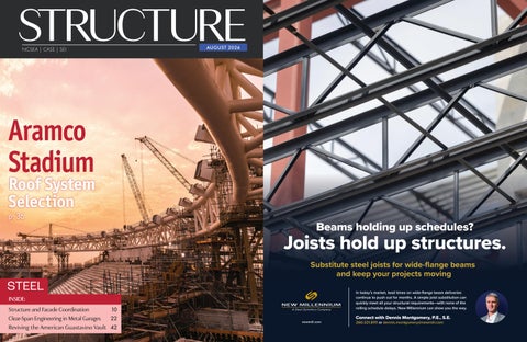
Aramco Stadium
Roof System Selection p. 36
Beams holding up schedules?
Joists hold up structures. STEEL
Substitute steel joists for wide-flange beams and keep your projects moving In today’s market, lead times on wide-flange beam deliveries continue to push out for months. A simple joist substitution can quickly meet all your structural requirements—with none of the rolling schedule delays. New Millennium can show you the way.
INSIDE: Structure and Facade Coordination 10 Clear-Span Engineering in Metal Garages 22 Reviving the American Guastavino Vault 42
newmill.com
Connect with Dennis Montgomery, P.E., S.E. 260.321.8111 or dennis.montgomery@newmill.com
P O W E R F U L R E S U LT S VISION MEETS
START HERE. VERSATILITY Complex designs. Tight timelines. Increasing
Break from the demands. norm withToday’s Vulcraftconstruction specialty joists performance
flexibility. Built for durability and versatility,
and steel deck. Our custom-engineered joist projects require more than standard solutions.
our products help transform complex designs
solutions pair seamlessly with high-performance Nucor Vulcraft-Verco delivers custom-engineered deck to deliver strength, efficiency, and design steel joists, deck, and bar grating that provide
into standout structures.
strength, efficiency, and design flexibility for demanding projects. In addition, we offer intuitive online tools and expert design guidance to ensure the right solution every time. As part of the Nucor family, we combine high-quality, low-embodied carbon steel with responsive service and on-time delivery to keep projects moving.
SCAN TO LEARN MORE
VULCRAFT
View our site to contact an expert today.
VERCO
POWERFUL PARTNERSHIPS. POWERFUL RESULTS.
ADVERTISER index
Please support these advertisers
STRUCTURE
®
CIRCULATION
ASC Steel Deck................................................................. 4 ASDIP................................................................................... 11 Bull Moose Industries....................................................... 23 CANAM.............................................................................. Inside Back Cover CAST CONNEX............................................................... 7 Chicago Clamp................................................................. 12 Computers & Structures Inc...................................................... Back Cover CTS Cement........................................................................ 28 ENERCALC......................................................................... 9 IDEA STATICA................................................................... 15 IES.......................................................................................... 3 LeJeune Bolt Company.................................................... 20 MAX USA CORP............................................................... 19 NCEES................................................................................. 55 New Millenium.................................................................. 24 Nucor................................................................................... 34-35 Nucor Vulcraft.................................................................... Inside Front Cover Steel Dynamics.................................................................. 17
subscriptions@structuremag.org
EDITORIAL BOARD Chair John A. Dal Pino, S.E. Claremont Engineers Inc., Oakland, CA chair@STRUCTUREmag.org Kevin Adamson, PE Structural Focus, Gardena, CA Marshall Carman, PE, SE Schaefer, Cincinnati, Ohio Erin Conaway, PE AISC, Phoenix, AZ Sarah Evans, PE Walter P Moore, Houston, TX Steven Judd Interstate Brick, West Jordan, Utah, and H.C. Muddox, Sacramento, California Linda M. Kaplan, PE Pennoni, Pittsburgh, PA Jessica Mandrick, PE, SE, LEED AP Gilsanz Murray Steficek, LLP, New York, NY Brian W. Miller Cast Connex Corporation, Davis, CA
August 2026
Evans Mountzouris, PE Retired, Milford, CT
Digital Issue
Kenneth Ogorzalek, PE, SE KPFF Consulting Engineers, San Francisco, CA (WI) John “Buddy” Showalter, PE International Code Council, Washington, DC
Available Only at
STRUCTUREmag.org
Eytan Solomon, PE, LEED AP TYLin, New York, NY
Publication of any article, image, or advertisement in STRUCTURE® magazine does not constitute endorsement by NCSEA, CASE, SEI, the Publisher, or the Editorial Board. Authors, contributors, and advertisers retain sole responsibility for the content of their submissions. STRUCTURE magazine is not a peer-reviewed publication. Readers are encouraged to do their due diligence through personal research on topics.
EDITORIAL STAFF Executive Editor Alfred Spada aspada@ncsea.com
Managing Editor Shannon Wetzel swetzel@structuremag.org
ADVERTISEMENT–For Advertiser Information, visit STRUCTUREmag.org
Get 15% off with STR2026 iesweb.com/str
MARKETING & ADVERTISING SALES
I E S
Senior Director for Business Development & Marketing Monica Shripka Tel: 773-974-6561 monica.shripka@STRUCTUREmag.org
Sales Manager Audrey Schmook Tel: 312-649-4600 Ext. 213 aschmook@ncsea.com STRUCTURE magazine (ISSN 1536 4283) is published monthly by The ®
Proven
structural software for over 30 years
Flexible
licensing to meet your needs
Reliable
support from professional engineers
National Council of Structural Engineers Associations (a nonprofit Association), 20 N. Wacker Drive, Suite 750, Chicago, IL 60606 312.649.4600. Periodical postage paid at Chicago, Il, and at additional mailing offices. STRUCTURE magazine, Volume 33, Number 8, © 2026 by The National Council of Structural Engineers Associations, all rights reserved. Subscription services, back issues and subscription information tel: 312-649-4600, or write to STRUCTURE magazine Circulation, 20 N. Wacker Drive, Suite 750, Chicago, IL 60606.The publication is distributed to members of The National Council of Structural Engineers Associations through a resolution to its bylaws, and to members of CASE and SEI paid by each organization as nominal price subscription for its members as a benefit of their membership. Yearly Subscription in USA $75; $40 For Students; Canada $90; $60 for Canadian Students; Foreign $135, $90 for foreign students. Editorial Office: Send editorial mail to: STRUCTURE magazine, Attn: Editorial, 20 N. Wacker Drive, Suite 750, Chicago, IL 60606. POSTMASTER: Send Address changes to STRUCTURE magazine, 20 N. Wacker Drive, Suite 750, Chicago, IL 60606. STRUCTURE is a registered trademark of the National Council of Structural Engineers Associations (NCSEA). Articles may not be reproduced in whole or in part without the written permission of the publisher.
AUGUST 2026
3
AU G US T 2 0 26
®
DELTAGRIP DG4
TM
ADVERTISEMENT–For Advertiser Information, visit STRUCTUREmag.org
The Better Way of Connecting Steel Roof Deck at Sidelaps
Contents
F E A T U R E S
ROOF SYSTEM SELECTION FOR ARAMCO STADIUM
By Padraic Leonard, Sultanh Algethami, and Khaled Almohaisen Patent Number: 11,872,644
36
Key parameters influence roofing system selection between standingseam metal and insulated sandwich panel in modern stadiums.
z Lightest Pneumatic Sidelap Tool z Increased Connection Strength z Improved Connection Stiffness z Enhanced Crimping Force z Upgraded Durability z Faster Cycle Time
42
42
REVIVING THE AMERICAN GUASTAVINO VAULT
By Margaret Cowie, PE
Restoration of the hybrid vaults at Michigan Central Station took careful planning and significant structural analysis.
ascsd.com/deltagrip-dg4
4
STRUCTUREmagazine
In Every Issue 3 Advertiser Index 56 SE News
58 SEI Update 60 CASE in Point 62 NCSEA News
P O W E R F U L R E S U LT S VISION MEETS
START HERE. VERSATILITY Complex designs. Tight timelines. Increasing
Break from the demands. norm withToday’s Vulcraftconstruction specialty joists performance
flexibility. Built for durability and versatility,
and steel deck. Our custom-engineered joist projects require more than standard solutions.
our products help transform complex designs
solutions pair seamlessly with high-performance Nucor Vulcraft-Verco delivers custom-engineered deck to deliver strength, efficiency, and design steel joists, deck, and bar grating that provide
into standout structures.
strength, efficiency, and design flexibility for demanding projects. In addition, we offer intuitive online tools and expert design guidance to ensure the right solution every time. As part of the Nucor family, we combine high-quality, low-embodied carbon steel with responsive service and on-time delivery to keep projects moving.
SCAN TO LEARN MORE
VULCRAFT
View our site to contact an expert today.
VERCO
POWERFUL PARTNERSHIPS. POWERFUL RESULTS.
C O L U M N S a n d D E PA RT M E N TS
8 Editorial
52 InFocus
Beyond the Toy Box: Building a Wider Base for the Profession
Building the Profession Alongside the Structure By CASE Coalition
By Ken O’Dell, SE and Natalie Tse, SE LEED AP
10 Structural Design
65 Structural Forum
So You Want to Start Your Own Firm Part 3: Finance & Accounting
Structure and Facade Coordination By Joseph Schuster, PE, SE, and Matthew Kuba, PE
By John Dal Pino
16
Structural Design
Seismic Strengthening of Existing Concrete Structures with FRP By Garrett Hagen and Aniket Borwankar
22
Structural Design
22
Clear-Span Engineering in Pre-Engineered Metal Garages and Shops for Residential Applications
26
By Logan Hermer
26 Structural Design
Harvesting Green Energy From a Gray Garage By Jake P. Phelan and Mike J. Bolduc
30
InSights
Adaptive Reuse for Affordable Housing: A Concurrent Feasibility Framework By Prital Shukla
48
48 InFocus
Natural Disasters and Their Impacts on Codes and Standards By Cherylyn Henry, PE, and Jessica Mandrick, PE, SE
52
6
STRUCTUREmagazine
CONNECT SEAMLESSLY CAST CONNEX® Diablo Bolted Splice™ (DBS) is a cast steel fitting that enables unobtrusive field bolted splices in circular hollow structural section (HSS) members. Pre-Drilled Screw Holes for Cover Plates
Pre-Drilled Screw Holes for Cover Plates
Engineered PreDrilled Bolt Holes
Cover Plate (Optional)
Diablo Cast Steel Splice
Cover Plate Screw
Structural Bolt
Washer & Nut HSS/Pipe Structural Steel Member
Weld bevel, allowing adjoining tubular members to be square-cut for shop welding.
Request sample specification and download Datasheets at: www.castconnex.com.
Learn More About this Product
Effortless to use as it eliminates field welding, and expertly designed such that the bolted connection is inboard of the outer diameter of the HSS.
Seamless DBS splice connectors are offered with thin-gauge plates to conceal the splice, although they can be left uncovered.
DIABLO BOLTED SPLICE™ info@castconnex.com | 1-888-681-8786
www.castconnex.com
Easy to Specify pre-engineered solution, available in sizes to fit a range of HSS/Pipe.
EDITORIAL Building the Profession Alongside the Structure By CASE Coalition
S
tructural engineering is a profession built on judgment, experience, and trust. Engineers learn the technical foundations of practice through education and training, but much of what makes someone effective in the profession is developed over time through exposure to projects, colleagues, mentors, and difficult decisions. That is why it is important to involve young professionals early. Early-career structural engineers are entering a profession that is becoming more complex. They are expected to understand evolving codes, new technologies, changing project delivery methods, risk management, client expectations, and the growing need for coordination across disciplines. At the same time, many are still learning how to communicate clearly, exercise professional judgment, and navigate situations that do not have an obvious answer. Those skills cannot be developed through technical work alone. Young professionals need opportunities to connect with peers, learn from experienced engineers, and see how others approach the challenges of practice. Professional organizations, technical groups, committees, and industry networks can provide those opportunities, but only when firms and senior professionals make a deliberate effort to bring younger engineers into the conversation. Too often, professional involvement is treated as something that comes later in a career, after an engineer has gained a certain title, completed licensure, or moved into management. By then, an important opportunity may have been missed. The earlier an engineer begins building a professional network, the more useful that network becomes. Connections made at the beginning of a career can grow alongside the individuals involved. A peer met through a committee, conference, or technical program may later become a trusted colleague, a source of advice, a project partner, or simply someone who understands the pressures of the profession. Those relationships can be particularly valuable for young engineers who work in small firms or highly specialized roles. They may have limited access to peers at a similar career stage within their own workplace. Professional involvement gives them a broader community and a chance to learn how other firms and teams operate. It also helps young engineers understand that many of the challenges they face are not unique to them. Questions about workload, communication, technical confidence, career development, licensure, and professional responsibility are common. 8 STRUCTURE magazine
A direct introduction, an invitation to speak, or a small assignment can make the difference between someone feeling included or deciding not to return. Being able to discuss those issues with peers can reduce isolation and help young engineers develop perspective. It can also make it easier for them to recognize when they need guidance and to seek it before a problem grows. Access to resources is another important benefit. The structural engineering profession produces a wide range of technical guidance, practice tools, contract resources, risk management materials, webinars, and educational programs. Yet young professionals may not know those resources exist, where to find them, or how to apply them. Early involvement can help bridge that gap. It exposes younger engineers to resources beyond the documents immediately required for their current assignments. It shows them where to look when they encounter unfamiliar issues and helps them build the habit of seeking out reliable professional guidance. That habit matters because structural engineers will repeatedly face situations that fall outside their direct experience. No engineer can personally encounter every building type, project condition, contractual issue, or technical challenge. A strong professional network and familiarity with trusted resources provide a way to learn from the collective experience of others. Young professionals also bring value to the organizations and groups they join. They enter the profession with different experiences, expectations, and ways of working. Many are comfortable with emerging technologies and new forms of communication. They may see inefficiencies or barriers that established professionals have come to accept. Their questions can reveal where existing guidance is unclear, outdated, or difficult to access. Involving younger engineers should not mean inviting them to observe from the back of the room. Meaningful participation requires giving them a role. That may include asking them to help plan an educational session, serve on a working group, contribute to a technical resource, participate in a peer discussion, or offer feedback on how information is communicated. These opportunities allow
young professionals to develop leadership and communication skills while contributing to work that benefits the broader profession. Mentorship is also more effective when it extends beyond a single firm. Internal mentors are essential, but external relationships provide a different kind of perspective. An engineer outside the workplace may be able to offer objective advice, share a different approach, or help a young professional understand how the profession varies across firms and markets. Professional involvement also helps young engineers see the larger context of their work. A calculation is never just a calculation. It exists within a project, a contract, a business relationship, a regulatory environment, and a responsibility to protect the public. Exposure to broader professional discussions helps younger engineers understand how those pieces fit together. That understanding supports better judgment. The profession should also recognize that participation is not equally accessible to everyone. Time, travel costs, workload, and a lack of encouragement can all become barriers. Firms that value professional involvement should make space for it by supporting attendance, allowing time for committee work, and treating participation as part of professional development rather than as an extracurricular activity. Senior engineers also have a responsibility to make professional spaces more welcoming. It can be difficult for a young engineer to enter a room filled with experienced professionals and feel confident enough to contribute. A direct introduction, an invitation to speak, or a small assignment can make the difference between someone feeling included or deciding not to return. The future of structural engineering will depend on more than technical competence. It will depend on whether the profession can develop engineers who are connected, informed, confident, and prepared to lead. That development should not begin after someone reaches management. It should begin early, while professional habits are still forming and while relationships have time to grow. By involving young professionals now, the structural engineering community is not simply preparing future leaders. It is strengthening the profession in the present. ■ Open to all ACEC members, the Coalition of American Structural Engineers (CASE) is recognized in the structural engineering industry for helping firms strengthen business practices, manage liability, and advocate for the profession.
When your spreadsheets stop scaling with your practice. Visible Code References Clear Pass/Fail Result
Clear Inputs
Responsive Graphics
Detailed Outputs
Professional tools for professional engineering. 30-day FREE Trial | enercalc.com
SINCE 1982
structural DESIGN Structure and Facade Coordination
Structural engineers can reduce the risk of facade-related litigation with these practical recommendations. By Joseph Schuster, PE, SE, and Matthew Kuba, PE
T
he concrete superstructure has topped out on your latest project, but there’s a problem. The window wall facade can’t be installed because the panels don’t fit between the slabs. The contractor blames your design, saying the slab edges are deflecting more than the panels can accommodate. You’re the structural engineer—you didn’t design the facade. Could this really be your fault? Facade systems are among the most complex building components, in part because they require close coordination among several parties. When facade problems occur, structural engineers can be drawn into disputes. In most facade litigation cases, the structural engineer is not the prime defendant. Design errors are generally attributable to the architect and facade designer (often under a contractor’s delegated design). Construction defects are generally attributable to the contractors. However, the structural engineer has an important role to play in achieving a successful facade design and installation. When those responsibilities aren’t met or when a structural engineer’s decisions directly contribute to facade installation and performance issues, the engineer can be sued. For cases involving construction delays or modifications to the facade or structure, damage claims can exceed the engineer’s design fees by orders of magnitude.
Know Your Responsibilities Most facade litigation claims stem from poor coordination between the design professionals and contractors. Structural engineers should understand their coordination responsibilities to minimize their facade claims risk. Standard practice is not directly defined in building codes, but guidance can be found in industry standards, such as: • AISC Design Guide 22, Facade Attachments to Steel-Framed Buildings. Section 3.3 discusses the roles and responsibilities for the various parties in the facade coordination process. While the guide is specific to steel buildings, the coordination responsibilities apply to many types of structures. • CASE Guideline 962, National Practice Guidelines for the Structural
Engineer of Record, includes a discussion of the typical scope of services for the structural engineer of record. Broadly speaking, the structural engineer is responsible for: • Designing slab edge details that can support facade-imposed loads and that are compatible with the selected facade attachment concepts. • Clearly communicating structural component tolerances at facade attachment points. By how much could the spandrel beam and slab edge locations vary from the locations specified? • Clearly communicating structural movements at the facade attachment points, including slab edge deflections, interstory drifts, differential column shortening, and more. • Reviewing facade submittals to confirm: - Loads imposed on the structure are consistent with structural design assumptions. - Connection details match design intent and are compatible with slab edge design. - Facade detailing aims to accommodate anticipated structural tolerances and movements. In the structural engineer’s contract, scope related to facade coordination should be clearly defined, along with explicit callouts for excluded tasks such as review of facade submittals beyond imposed loads and connection tolerance capability.
Common Errors Facade litigation claims against design professionals have a few recurring themes in terms of coordination, design, and installation.
Inadequate Support for Facade Components This straightforward design error occurs when slab edge or spandrel beam details designed by the structural engineer are not sufficiently stiff to limit deflection or not sufficiently strong to provide adequate
Fig. 1. Left: As shown in this illustration from AISC Design Guide 22, minor spandrel rotations can create large deformation at the facade support points. Right: Spandrel rotation is typically addressed through full-depth stiffeners or diagonal braces (kickers) connected to the spandrel bottom flange. (Figures copyright American Institute of Steel Construction. Reprinted with permission. All rights reserved.)
10 STRUCTURE magazine
YOUR DESIGN SIMPLIFIED.
The All-In-One Structural Engineering Software used by professionals worldwide. USER-FRIENDLY INTERFACE | POWERFUL DESIGN CAPABILITIES | CLOUD-BASED WWW.ASDIPSOFT.COM
SUPPORT@ASDIPSOFT.COM
Fig. 2. Left: Brick masonry will expand after installation, while CMU will shrink. Right: Inadequate jointing of the brick facade can lead to cracking and spalling.
When Good Labor is Short, Why Not Make the Job Easier? Joist Grip Framing Clamp System
ADVERTISEMENT–For Advertiser Information, visit STRUCTUREmag.org
Support your rooftop loads in uplift and download conditions. The distributed load capacity of 4,000 lbs per complete system makes the Joist Grip Framing Clamp System the ideal support for rooftop unit installations.
Pipe Header System Hanger Clamps, rated for 1,000 lbs each allow hanging of equipment below the roof deck while utilizing the ability of the Framing Clamps to distribute the load to panel points on the top chord of the bar joist.
Suspension Clamp System Panel Point Bridge Utilize the Panel Point Bridge to safely suspend HVAC equipment, conveyors or other ceiling fixtures without welding or drilling using the Suspension Clamp System.
Upper Deck Fall Protection System Using corrugations in the standard roof deck, the Upper Deck Fall Protection Anchorage System easily clamps to the top chord of the bar joist or wide flange support. Visit with
Chicago Clamp Company Booth #852 at the upcoming
NASCC: Steel Conference in Atlanta Plan your next project using Chicago Clamp Systems™
708.343.8311 12 STRUCTURE magazine
support for the facade. Inadequate stiffness is far more common than insufficient strength. Frequently, deflections are an issue at unreinforced masonry facades, where the spandrel beams and lintels must typically be designed for a dead + live load deflection of L/600 (TMS 402, Building Code Requirements for Masonry Structures, Section 5.2.1.4.1)—much more restrictive than the deflection requirement for typical steel framing members. Deflection requirements for spandrels and lintels should always be confirmed with the architect and facade designer. Failure to design to the deflection requirements can result in cracking, visible deflections, and other serviceability problems. For heavy facades (e.g., brick, stone, and concrete), the structural engineer must also pay close attention to torsional rotations of the spandrel beams. If the facade is highly eccentric to spandrel beams of a steel-framed building, a small amount of spandrel rotation can result in significant deformations at the facade support locations (Fig. 1). While facade panels anchored at two successive floors during installation may help to restrain outward tilt at the building’s lower stories, the problem can resurface at the top floor/parapet, where the facade cannot provide rotational restraint. Check spandrel rotation and, where required, design kickers or full-depth shear connections to minimize torsional effects. Inadequate strength can be an issue when communications are insufficient. Examples include changes in facade support strategies, loading locations, weights, and other forces that occur after the structure is designed. To avoid that communication gap, diagrams on structural drawings clearly showing typical facade loads and support arrangements used for framing design can provide a basis for discussions.
Movement Incompatibility Facade installation problems can arise if structural and facade movements are incompatible. Most structural engineers know to present
Fig. 3. Example sketches for effective means of communicating concrete slab edge tolerances.
anticipated slab edge live load deflections and interstory drifts on drawings for use by the facade designer. In practice, these movements are rarely the source of facade failures. One reason may be the reality that most buildings never experience design seismic and wind events or full design live load. While these movements must be properly communicated to the facade designers, other types of movement— such as thermal, moisture expansion, and creep behaviors—are more commonly overlooked and more likely to result in performance issues. Masonry facades can prove particularly tricky for designers who are not aware of one simple fact: in contrast with concrete shrinkage, brick masonry expands after installation, as it absorbs moisture from the atmosphere. Consider a cavity wall facade with a concrete masonry unit (CMU) bearing wall as backup for a clay brick exterior wythe. For this type of construction, the CMU structure and brick exterior move in opposite directions. The brick undergoes moisture and thermal expansion, while the CMU experiences drying shrinkage as well as axial shortening as loads are added. Failure to detail the brick facade with sufficient joints of suitable width to accommodate the total relative movement can result in cracking and spalling of the masonry (Fig. 2). While the architect is typically responsible for this detailing, developing appropriate details without input from the structural engineer is difficult. Brick and CMU movements are determined from shrinkage and expansion coefficients that come from Section 4.2 of TMS 402. Further detailing recommendations are available in Tech Note 18A, Accommodating Expansion of Brickwork, published by the Brick Industry Association (BIA). Structural engineers should be familiar with these recommendations and should confirm that the facade designers have the structural movement information needed. Building lateral displacements under gravity loads can also adversely impact facade installation. Consider a high-rise concrete building with an offset elevator core. Experienced structural engineers would anticipate that during construction, the building will begin to lean away from the core due to larger axial deformations and creep of columns under gravity loads compared to the less-stressed core. In recent facade litigation, the structural engineer of record correctly calculated during the design phase that a 50-story building would lean by approximately six inches. The lean was accounted for in the structural model, so the structural engineer did not see a need to communicate the magnitude to the remainder of the design team. Unfortunately, the aluminum facade panels were detailed with much less adjustability than required to accommodate the building movements. The panels could not be made to fit around the corners of the leaning superstructure and needed to be refabricated. For tall concrete structures, best practice is to discuss building lean magnitudes early in the design process. In this case, costly facade panel refabrication could have been avoided by structural compensation measures during
construction, such as column cambering, by facade panels with more adjustability, or a combination of measures.
Poor Communication of Slab Edge Deflections and Tolerance Closely related to the issue of movement incompatibility is failure by the structural engineer to communicate slab edge deflections and tolerances. Contractors understand that facade attachment points may not end up exactly where they were specified to be. But input from the structural engineer is required for the contractor to understand exactly how much they will deviate. Structural tolerances should be communicated during the design development phase, or even earlier, so the facade can be detailed accordingly. The structural engineer should provide actual construction tolerance values instead of general references to the standards. For example, a sketch that shows that the slabs on a concrete building may be ¾ inches higher or lower than specified is much more helpful than a note broadly stating that the facade must accommodate tolerances from ACI 117 (Fig. 3). Specifying erection tolerances more stringent than those provided in industry standards (e.g., ACI 117 Specification for Tolerances for Concrete Construction and Materials, and AISC 303 Code of Standard Practice for Steel Buildings and Bridges) should be considered only for special circumstances, with the implications discussed ahead of time with the design team and contractors. Similarly, slab edge deflections must be clearly communicated on the design documents. A facade designer will want to know three things: 1. How much the slabs will have deflected at the time the facade
Fig. 4. Concrete slab deflections can create installation issues for window wall systems, which must fit between the slabs. AUGUST 2026
13
is being installed. The slab edge deflection values must be combined with the construction tolerance to get the total potential slab edge deviation. The facade designer should know to do this, but it is good practice for the structural engineer to confirm. 2. How much more will the slab deflect after the facade is installed (due to superim- Fig. 5. This slab edge deflection note created confusion for the facade designer. Does the long term posed dead loads, live loads, and creep). total deflection include or exclude the short term deflections? What’s included in the “Short Term DL” 3. Interstory drifts due to wind and seismic deflection? loads, with clearly identified load factors (e.g., wind service drift = h/400 max under 0.7W). types and locations of the planned facade anchors. The structural drawSeparate deflection and story drift values should be provided for atypi- ings should include diagrams showing facade loads and locations, along cal conditions, such as podium floors or longer spans; it is inefficient to with exclusion areas where facade anchorage is not permitted (e.g., as design the entire facade to accommodate worst-case deformations that seismic deformation zones and areas with post-tensioning strands). occur at only a few bays or stories. Buildings with window wall facade For concrete buildings, conflicts between rebar and facade anchors systems require additional attention to detail. Unlike curtainwalls, which can cause serious construction delays. To avoid these headaches, the typically have generous adjustability, window walls must fit between best practice is for the structural engineer to work with the architect the slabs. Problems occur most frequently when window wall facades and contractor to ensure the implementation of one of the following are used in conjunction with non-prestressed concrete slabs that have strategies: aggressive span-to-thickness ratios. Because window wall head tracks • Use cast-in anchor channels instead of post-installed facade are often set straight and level, slabs with significant deflections can anchors to provide location flexibility. While these systems have “pinch” the available clear dimension between slab (Fig. 4). an upfront cost, cast-in anchors are the most effective way to Deflection information should also be clear and easy to follow. The genprevent facade anchor/rebar conflicts. eral notes excerpt in Figure 5 comes from a set of structural drawings. The • Perform rebar scans using ground penetrating radar (GPR) after facade designer interpreted the note to indicate that the total maximum slab placement to mark bars on the slab. This approach must also slab edge deflection was 1.23 inches, inclusive of both the “Short Term incorporate facade anchorage detailing with sufficient adjustLL” and “Short Term DL” values. The structural engineer later testified ability so that post-installed anchor locations can be adjusted in that the values were additive; the total maximum slab edge deflection was the field to avoid the rebar. actually 1.23 inches + 0.28 inches + 0.77 inches = 2.28 inches (close to • Mark no-fly zones. By having facade anchor locations marked twice as much as what the facade designer had considered). It was also on the forms, the contractor can make minor adjustments to unclear what loads were included in the “Short Term DL” deflection. rebar placement to avoid conflicts. This option requires the most Clearer communication of the slab edge deflections could have prevented coordination between the trades. serious facade installation issues that led to a lawsuit. While the general contractor is responsible for overseeing coordination between the concrete and facade subcontractor, the structural Structure and Facade Attachment Conflicts engineer should avoid making the coordination more difficult than necessary. In one facade litigation case, the structural engineer insisted, While the structural engineer of record does not typically design the for no clear structural engineering reason, that edge rebar be located facade attachments, they should still have some understanding of the exactly 3 inches from the edge of the slab—directly in line with the facade anchors. Not surprisingly, the contractor blamed the structural engineer for the resulting anchor conflicts.
Recommendations for Facade-Structure Coordination
Fig. 6. Example slab edge section cut with clear communication of facade loading assumption. Detail shows location of imposed loads, with load magnitudes, Fx and Fz, listed in a separate table (not shown). Notes clearly delegate the final connection design to the curtain wall contractor.
14 STRUCTURE magazine
Involvement from the structural engineer is required throughout the design and construction process to help facilitate a smooth facade installation process. With that in mind, the following is a list of key items for the structural engineer to consider during each phase of the project:
Design Phase Review the facade concept with the architect to identify potentially problematic conditions. For example, speak up if the design team and owner are pushing for unusually thin concrete slabs and long spans. Suggest that the project team consider details that can prevent facade installation conflicts, such as cast-in facade anchors instead of post-installed anchors. Communicate structural movements and tolerances to the design team so that the facade can be detailed accordingly from the get-go. For concrete structures with long-term creep, make sure the facade designer understands both the initial and long-term slab edge movements, and that the tolerances and deflections must be combined to get the total potential slab edge deviation.
Construction Documents Include section cuts that clearly show the structural slab edge details with the relationship to the facade. Clearly list the structural movements (slab edge deflections, inter-story drift, creep, etc.) and structural tolerances in the construction documents. Provide the actual +/- tolerance values, not just references to industry standards.
Construction Administration Review facade submittals, while including clear disclaimer language indicating you have not designed the facade and that your review is limited to reviewing loads imposed on the structure. Look for and
take exception to potentially problematic facade detailing, such as inadequate facade adjustability and facade anchorage details that will potentially conflict with structural components.
Construction Require the contractor to perform slab edge surveys before and after the shores are removed. Review the first few surveys to identify slab placement tolerance issues or slab deflections that exceed what would be predicted by analysis. Every project is different, and the recommendations in this article are not always applicable. However, facade coordination is not something that the structural engineer can ignore. Being a proactive participant in the coordination process—and being aware of the common coordination pitfalls—can go a long way in preventing facade disputes and potentially substantial litigation costs for structural engineers. ■
Joseph Schuster, PE, SE, is a Principal at Thornton Tomasetti and leads the forensics practice in TT’s Newark office. His work focuses on facade and structure-related litigation support work, including expert testimony. Matthew Kuba, PE, is a Principal at Thornton Tomasetti and is the Midwest Regional Facade Engineering practice leader. He specializes in facade analysis and investigation, including finite element modeling and thermal performance analysis of glass and steel specialty structures.
ADVERTISEMENT–For Advertiser Information, visit STRUCTUREmag.org
CONNECTION DESIGN AT ITS BEST Design any connection Steel anchorage workflow Integrates with your software Grouping and Batch design Parametric templates
www.ideastatica.com
Try the full version for 14 days for free AUGUST 2026
15
structural DESIGN Seismic Strengthening of Existing Concrete Structures with FRP
Current fiber-reinforced polymer (FRP) strengthening guidance and emerging research have practical design implications for practicing engineers. By Garrett Hagen and Aniket Borwankar
F
iber-reinforced polymer (FRP) composites have become a widely accepted solution for strengthening existing concrete structures. While established guidance exists for gravity, flexural, and column confinement applications, seismic strengthening with FRP has historically lacked clear, consensus-based design direction. In recent years, this gap has narrowed due to targeted experimental research, jurisdictional guideline development, and ongoing updates to national standards. Recent advances include large-scale testing, ongoing work in the consensus standards, and the development of retrofit guidelines like the City of West Hollywood FRP guidelines and HCAi PCS preapproval guides, whereby the community works toward a coherent framework for applying FRP to seismic retrofit projects involving columns, walls, diaphragms, collectors, and chords.
Why FRP Retrofit Guidance Is Evolving Now A large inventory of existing concrete buildings in seismic regions was constructed prior to the introduction of modern detailing
requirements for deformation compatibility, transverse reinforcement, and complete seismic load paths. Common deficiencies include inadequate shear strength in columns and walls, insufficient confinement, thin or lightly reinforced diaphragms, and collectors designed only for gravity loads. While performance-based seismic evaluation methodologies in ASCE 41 and the corresponding concrete provisions from ACI 369 have shifted engineering practice toward displacement-based evaluation and component-level performance objectives for existing buildings, little retrofit design guidance has been provided for FRP enhancement of deficient concrete components. FRP strengthening has grown rapidly as an attractive retrofit option due to its high strength-to-weight ratio, minimal added mass, and constructability advantages. However, much of the existing FRP guidance, particularly ACI 440.2R, was developed primarily for force-based strengthening of beams and columns under gravity or monotonic loading. Direct extension of these provisions to seismic applications, characterized by cyclic loading and the post-yield deformation demands of the retrofitted concrete component (rather than of the FRP itself, which remains essentially linear-elastic to rupture), has led to inconsistent interpretation and application. This article summarizes recent research, code development, and field experience that collectively establish a clearer design basis for FRP seismic strengthening of existing concrete structures, with an emphasis on practical implementation for structural engineers.
Historical Context: What Existing FRP Guidance Was (and Was Not) Designed For
An FRP collector with a composite plate anchorage system is shown.
16 STRUCTURE magazine
The ACI 440 family of documents established the foundational framework for externally bonded FRP strengthening in the United States, building on earlier evaluation criteria such as ICC-ES AC125, first issued in 1997. The first design guidance arrived with ACI 440.2R-02 in 2002 (preceded by the companion ACI 440.1R01 in 2001), with subsequent editions in 2008 and 2017. These provisions target a minimum safety objective and applications
Building Construction
HighStrength Steel MADE STRONGER. MADE SMARTER.
A572-65, as offered by Steel Dynamics, is high-performance structural steel, engineered for superior strength and durability through advanced microalloying. With a minimum yield strength of 65 KSI, A572-65 delivers enhanced mechanical performance—making it the ideal choice for heavy construction, critical infrastructure, and large-scale projects. Manufactured in the USA to meet or exceed ASTM specifications, A572-65 provides the confidence engineers demand and the reliability builders trust.
For more information, visit lpg.steeldynamics.com or email us at high-strength@steeldynamics.com.
with relatively well-defined stress states, short bond lengths, and limited cyclic demand, such as shear and flexural strengthening of beams and columns. Seismic strengthening, by contrast, must accommodate repeated load reversals, reinforcement yielding, and force redistribution while maintaining deformation compatibility, with the governing performance objective often being deformation capacity rather than peak strength. Absent seismic-specific guidance, engineers were forced to extrapolate from these gravity-based provisions, leaving uncertainty regarding force and ductility reduction factors, usable strain limits, anchorage and detailing requirements, and acceptance criteria. Recent research and guideline development are beginning to resolve these inconsistencies.
Seismic Retrofit Applications of FRP in Concrete Buildings FRP seismic strengthening strategies can be broadly categorized by structural component type. Columns, walls, diaphragms, collectors, and chords form an integrated seismic load path and must be addressed holistically in retrofit projects. FRP strength and detailing design is often delegated to an FRP vendor-provided engineer, which leads to many disconnects between the integrated seismic system and the component action requirements that are affected by supplemental FRP. More clear guidance is needed both for consistency in design applications and for mitigating disconnects in information between the building project engineer and FRP providers. As is common practice with the design of typical seismic force-resisting systems, the building project engineer should be comfortable taking responsible charge for the entirety of the structural system, including the enhancement and interaction of FRP-retrofitted components. Indeed, certain jurisdictions do not permit delegated or deferred design of FRP strengthening at all: the Division of the State Architect (DSA), California Healthcare Agency, HCAi / OSHPD, and the City of West Hollywood do not accept deferred approval of FRP systems, and the structural engineer of record (SEOR) is therefore responsible for the full integrated design of the combined FRP and seismic system. The following design objectives are beginning to be better documented in FRP guidelines and consensus standards update proposals.
Columns: Shear Strengthening and Ductility Enhancement Shear Strengthening. For existing reinforced concrete columns with inadequate transverse reinforcement, the primary objective of FRP shear strengthening is to prevent brittle shear failure and ensure flexure-controlled behavior. FRP is proportioned to supplement deficient shear capacity such that the nominal shear strength exceeds the shear corresponding to development of 18 STRUCTURE magazine
expected flexural strength, establishing a clear hierarchy of strength and failure mode consistent with ASCE 41 objectives. Ductility and Confinement. FRP jacketing is also widely used to enhance column ductility through confinement of the concrete core. Two complementary approaches are commonly used in practice: 1. Direct application of ACI 440 confinement models to estimate enhanced concrete strength and ultimate strain capacity. 2. In the West Hollywood Appendix F Sections 8.2.1, 8.3.1, and 9.3, an equivalency-based approach is used in which FRP confinement is translated into an equivalent volumetric transverse reinforcement ratio, allowing direct use of ASCE 41 column modeling parameters and acceptance criteria. Both approaches are recognized in recent retrofit guidance and allow FRP-confined columns to be integrated consistently into ASCE 41 nonlinear analysis and acceptance frameworks. NIST Guidelines for Seismic Design and Evaluation of Concrete Members Retrofitted Using Externally Applied FRP PART I: FRP Jacketed Concrete Columns provides further recommendations on modeling and acceptance criteria which is analogous to the provisions of conventional concrete columns.
Walls: Shear Strengthening and DeformationCompatible Behavior
For reinforced concrete shear walls, FRP retrofit objectives depend strongly on wall geometry, aspect ratio, existing reinforcement, and quality of existing concrete. It is noted that older buildings have been known to exhibit concrete strength as low as 1,500 psi or less, which can limit FRP bond. Flexure-Controlled Wall Retrofits. Where geometry permits, FRP can be designed to increase shear strength such that flexural yielding of the vertical reinforcement governs wall response. In this case, wall behavior is governed by flexure, which is treated as deformationcontrolled under ASCE 41, and FRP debonding does not control global wall performance. Shear-Controlled Wall Retrofits With Deformation Capacity. Many existing walls are too squat to be practically converted to flexure-controlled behavior. Recent large-scale experimental programs, including testing performed by Simpson Strong-Tie in collaboration with academic and industry partners, have demonstrated that shear-controlled walls can nevertheless achieve stable, deformation-compatible behavior when robust FRP anchorage is provided (while the Simpson Strong-Tie results are not published, for example, the diaphragm test programs reported in Virginia Tech Report CE-VPI-ST-23-07 and the FRPRCS-16 work of Zhang et al. show similar behavior for diaphragm shear and collectors sustaining strength beyond delamination). In these tests, anchors maintained FRP tension capacity after initial debonding, allowing sustained lateral strength, stable hysteretic response, and distributed damage. The City of West Hollywood FRP Shown is a concrete wall-slab connection with Biguidelines (Appendix F Sections 8.2.2, directional FRP fabric. 8.3.2, and 10.0) explicitly recognize
this deformation-controlled shear behavior and prescribe modeling parameters and acceptance criteria for FRP-strengthened shear walls whose governing action remains shear-controlled. These provisions are aligned with ASCE 41-23 wall acceptance criteria and are supported by observed experimental behavior.
Diaphragms, Collectors, and Chords Seismic retrofits frequently identify deficiencies in diaphragm shear strength, collector tension capacity, and chord continuity. FRP offers distinct advantages for these components due to its minimal added thickness (e.g., roughly a quarter inch) and ability to be installed on the top surface of slabs, thereby avoiding conflicts with architectural finishes and mechanical systems. Recent research and guideline development have clarified appropriate strain limits, anchorage requirements, and acceptance criteria for these applications. FRP Tension Ties and Collectors. Collectors and tension ties are typically classified as force-controlled components. Research by Zhang et al. and others has demonstrated that debonding governs usable FRP strain in long and thick ties. Anchorage detailing directly influences whether conservative lower-bound or median debond strain limits are appropriate. Current jurisdictional guidance, for example West Hollywood Guideline Appendix F, Section 13.0, generally requires at least moderate anchorage, permitting median strain limits consistent with experimentally observed behavior. It is noted that minimum concrete thickness limitations are generally consistent for FRP anchors as to other epoxy anchor types. FRP for Diaphragm Shear. Beam analogy remains the predominant
framework for evaluating diaphragm shear. Experimental studies conducted at Virginia Tech have demonstrated that FRP can significantly enhance diaphragm shear strength and stiffness (concrete component yield deformations are generally constant for a given geometry, but strength is increased with FRP). Debond strain limits developed for column applications have been shown to provide reasonable predictions for diaphragm strengthening when adequate anchorage is provided.
Seismic Demand Considerations: Why Forces and Deformations Matter Establishing Seismic Demand ASCE 41 Tier 3 procedures permit both linear and nonlinear analysis methods to establish seismic demands. Beam analogy remains common for diaphragms and collectors, while finite-element shell models with section cuts are increasingly used to capture force transfer and amplification effects. Regardless of the analysis method employed, engineers must ensure that demand estimation is consistent with the assumed load path and deformation mechanisms.
Deformation Compatibility FRP behaves as a linear-elastic material and, absent special detailing, is classified as force-controlled under ASCE 41. However, experimental
ADVERTISEMENT–For Advertiser Information, visit STRUCTUREmag.org
AUGUST 2026
19
evidence demonstrates that when appropriate anchorage is provided, FRP-strengthened components can sustain significant deformation while maintaining load-carrying capacity. As a result, identifying realistic usable strain limits, rather than ultimate fiber rupture strain, is central to seismic FRP design. It is noted that the West Hollywood Guidelines, Appendix F Sections 8.1 and 8.2, provide guidance for component action classification for both existing and FRP-retrofitted components in the context of ASCE 41.
Anchorage Design and System Reliability While FRP systems have traditionally relied on adhesive bond to the concrete, progressive debonding is brittle in nature, and the combination of concrete cracking and debonding can degrade
concrete more than concrete alone. Given the variability of seismic response, FRP anchoring can provide a more reliable load transfer mechanism even after delamination has occurred, allowing for more deformation capacity of the strengthened component. Recent large-scale testing, including programs conducted at University of Aukland and Virginia Tech, has demonstrated that properly detailed anchorage maintains FRP tension after debonding, limits damage localization, and significantly enhances reliability and deformation capacity.
Types of Anchorage and Practical Detailing Several anchorage approaches are used in practice, and the article distinguishes among them because their reliability can differ: • Embedded FRP anchors — dry or pre-saturated fiber bundles inserted into drilled holes and splayed into a fan over the laminate. These are widely used but require specialized installation, are highly sensitive to installer skill, and cannot be meaningfully inspected once installed. Pre-saturated or pre-cured anchors exhibited more predictable performance, with narrower distribution or predicted results, compared to bundled anchors (or field cured anchors), which showed significant scatter (Zhang et. Al, 2026) • FRP through anchors—used to develop the FRP through the member thickness, particularly at diaphragm-to-wall and collector-to-wall transfers.
ADVERTISEMENT–For Advertiser Information, visit STRUCTUREmag.org
FASTENING THE FUTURE FOR THE PAST 50 YEARS
TNA® is the only fastening system that delivers both a quantifiable Snug Tight condition – ensuring every bolt in a connection meets a minimum requirement for tension – and the precise required angle for the perfect final pretension. No other system or method can match the TNA® Torque + Angle Fastening System for producing the highest level of accuracy and reliability in both the snug and final tensioning processes. Our TNA® Bolts meet the requirements of ASTM F3148 and are 100% Melt & Manufacture in the U.S. The Combined Method (Torque + Angle) is an approved RCSC installation method.
www.tightenright.com
SPEC APPROVALS & CERTIFICATIONS ASTM F3148-17a Specification | RCSC Specification for Structural Joints Using High-Strength Bolts; Combined Method of Installation ANSI/AISC 358 Prequalified Connections for Special & Intermediate Moment Frames for Seismic Applications AISC 360-22 Specification for Structural Steel Buildings | AASHTO LRFD Bridge Design Specifications, 10th Edition AASHTO LRFD Bridge Construction Specifications, 4th Edition, 2024 Interim Revisions AASHTO Steel Bridge Fabrication Specifications, 1st Edition | AREMA Manual for Railway Engineering
800.872.2658 | lejeunebolt.com | sales@lejeunebolt.com ©2026 LeJeune Bolt Company | All Rights Reserved. | Images used with permission. | TNA® is registered in U.S.A. Patented.
20 STRUCTURE magazine
Concrete shear wall strengthening with CFRP is shown.
• Proprietary prefabricated plate-and-fastener systems (e.g., Fyfe Duktil plates)—prefabricated composite plates combined with conventional concrete screws or wedge anchors. Effective anchorage design prioritizes avoidance of brittle concrete failure modes, promotion of load redistribution following debonding, and constructability. Experimental results indicate that anchored FRP provides the most robust and reliable seismic performance. Testing has also demonstrated that the type of anchorage used can result in differences in overall performance, which may be considered depending on the engineer’s desired performance considerations. The traditional embedded FRP anchors have been shown to have inconsistent results due to the required specialized installation procedures, the skill level of the installer and the inability to perform any meaningful inspection once the anchors are installed. Prefabricated composite plate anchors with conventional concrete screws or wedge anchors have been shown to provide improved performance when compared to the FRP anchors, while they are more easily installed and can be easily inspected on site. Again, minimum concrete thickness is generally aligned with other applications of the analogous anchor types.
System-Level Considerations FRP retrofit must be evaluated at the system level to ensure continuity of the seismic load path and compatibility with existing reinforcement and adjacent components. Strut-and-tie representations are often useful for understanding node behavior and force transfer. Construction quality control is critical, as FRP performance is highly sensitive to surface preparation, installation procedures, and inspection.
Emerging Standards and Future Direction The City of West Hollywood has adopted comprehensive FRP retrofit guidelines for non-ductile concrete buildings, representing one of the most complete jurisdictional frameworks for seismic FRP strengthening currently in use. These guidelines integrate ASCE 41 analysis procedures with explicit FRP design requirements for columns, walls, diaphragms, collectors, and chords. In parallel, the California Department of Health Care Access and Information (HCAi) is reviewing FRP preapproval criteria structured similarly to the West Hollywood provisions. At the national level, updates to ACI 440 and ACI 369 are underway, informed by recent research, testing, and practitioner experience.
Conclusions Recent research and ordinance-level guidance have substantially advanced the state of practice for FRP seismic strengthening of existing concrete structures. Key lessons include the importance of deformation-compatible design, the central role of anchorage in governing performance, and the need to evaluate retrofit measures at the system level. As national standards continue to evolve, practicing engineers now have a clearer and more reliable framework for employing FRP in seismic retrofit projects. Effective FRP seismic design requires not only robust detailing but also clearly specified field testing for FRP fabric as well as anchorage systems. ■
Full references are included in the online version of the article at STRUCTUREmag.org.
Garrett Hagen, SE is a Principal at Degenkolb Engineers, with 15 years of experience in design, evaluation, and retrofit of buildings in high-seismic regions. Based in Southern California, his work focuses on performancebased seismic engineering, seismic risk mitigation, and the implementation of innovative structural systems.
A FRP tension member undergoes cyclic testing on low strength concrete. (Courtesy: University of Auckland Structures Testing Lab)
Aniket Borwankar is the Director of Strategic Engineering at Fyfe (a Henkel Company), based in Southern California, where he works within the Civil Composites team. He brings over 17 years of experience in structural engineering, including a decade focused on the design, evaluation, and retrofit of building systems, and more than 7 years specializing in fiber-reinforced polymer (FRP) composites.
AUGUST 2026
21
structural DESIGN Clear-Span Engineering in Pre-Engineered Metal Garages and Shops for Residential Applications
In this column-free interior of a clear-span metal building, rigid-frame geometry carries the roof load to the sidewall columns, leaving the full width open for vehicle storage and shop use.
As more homeowners choose metal buildings over traditional wood-frame construction for vehicle storage and workshop space, structural engineers are increasingly involved in the design review and permitting process for these structures. By Logan Hermer
R
esidential pre-engineered metal buildings (PEMBs) have moved out of the rural agricultural lane and into mainstream suburban and exurban lots over the last five years. Structural engineers who once saw a residential PEMB drawing package only on the occasional ranch project now see them land on permit-review desks for twocar suburban garages, hobbyist shops on five-acre exurban lots, and single-tenant rural shops attached to primary residences. The volume has changed the review workload and with it the questions that arrive from the authority having jurisdiction (AHJ). This article maps that shift from the supply side of these buildings, where the order patterns, the catalog conventions, and the homeowner questions surface first. The structural judgment stays with the reviewing engineer. The aim is to describe what arrives on the desk and why, so the review and the client conversation start from common ground.
What Ships in the Manufacturer Package The homeowner-purchased PEMB package is the source of the new workload. The shell ships with manufacturer-stamped drawings from a delegated engineer working for the supplier, covering the frame, the secondary members, the bracing, the base reactions, and the anchor bolt requirements. Depending on the jurisdiction, the AHJ may accept that package outright, may require a wet-stamp from a local structural engineer, or may route the package to an independent reviewing engineer for site-specific verification. The package rarely needs a top-to-bottom redesign. What it does not include is the part tied to the specific lot. Wind speed, 22 STRUCTURE magazine
ground snow load, exposure category, soil bearing capacity, and slab thickness all depend on where the building lands. The reviewing engineer is also the person the building department calls when the homeowner asks about adding a lift, hanging a hoist, or framing in a future mezzanine, and those requests sit outside the manufacturer’s stamped scope.
Frame Geometry for Common Residential Sizes Clear-span PEMB geometry at residential scale clusters around six common widths, each paired with a predictable eave height range. The frame style changes with width, and that difference shows up on the manufacturer drawings before any review begins. • 20 feet and 24 feet widths: Light-gauge tubular rigid frames are the common geometry. Eave heights typically run 8 feet to 10 feet for residential garage use. These frames ship with a single straight column on each sidewall and a peaked rafter assembly that connects with bolted moment plates. • 30 feet width: The threshold where heavier C-section or built-up I-section primary frames start to appear. Eave heights of 10 feet and 12 feet are the residential workhorse pairings, especially for homeowners planning a two-post lift. • 40 feet width: Tapered-column rigid frames begin to dominate the manufacturer catalogs at this width. Eave heights of 12 feet and 14 feet are common, with 14 feet requested by buyers planning RV bays.
• 50 feet and 60 feet widths. Tapered-column rigid frames are the standard geometry. Eave heights of 14 feet and above are common. Residential use at these widths is usually a shop or shop-house combination rather than a pure garage. Member sizes, moment values, and deflection criteria live on the manufacturer’s stamped drawings, not in the width and height alone. Two packages at the same nominal size can carry different members depending on the supplier and the load order, so the drawing set is the reference, not the catalog page. A tapered-column frame also carries different anchor bolt callouts than a straight-column frame at the same width, which matters when comparing two quotes.
Where the Frame Meets the Foundation The connection between the PEMB column base and the concrete foundation is the single most common point of confusion in residential PEMB permitting. The manufacturer ships a base plate with a predefined anchor bolt pattern, an anchor bolt diameter, an embedment depth, and a required concrete compressive strength. What the manufacturer does not ship is the foundation design that confirms the concrete around the anchor delivers that capacity on the actual lot. Residential PEMB foundations in the U.S. most often take one of two forms. The first is a monolithic turn-down slab with a thickened perimeter, typically 12 to 18 inches deep at the perimeter and 4 to 5 inches in the field. The second is a separate strip or pad footing under each column line, with a non-structural slab on grade poured separately. The base plate callouts usually assume the thicker perimeter section is present, so the foundation is where the manufacturer’s scope ends and the site engineer’s begins.
Three mismatches surface most often when a catalog package meets a real lot. The foundation depth on the site plan may not match the embedment the base plate assumes. The rebar detailing may not match what the anchor pull-out calculation assumes. The concrete strength ordered for the pour may not match the value on the anchor calculation. Each of those is a site-specific call, which is why the foundation almost always needs its own design rather than a copy of the catalog detail.
Wide Openings and Open-Wall Shops Open-wall configurations are common in residential metal shops, and they are one of the most frequent upgrade triggers on the order side. A two-car garage with a single 16-feet-wide roll-up door in the gable end is a standard catalog package. A shop with a 30-feet wide opening across most of a 40-feet sidewall, with no infill above, usually is not. The manufacturer’s drawings handle lateral load in these layouts through portal frames at the opening, X-bracing in the opposite sidewall and at least one endwall, and roof diaphragm action between them. When a buyer asks for an opening that takes up most of a tall sidewall, the standard catalog package often is not the one that ships. The supplier routes that order back for additional engineering, and the reviewing engineer confirms the result against the site demand under ASCE 7.
Regional Patterns in Catalog Specs and Upgrade Orders Across residential clear-span PEMB orders, a few recheck items cluster by region. The Gulf Coast wind belt from Texas to North
ADVERTISEMENT–For Advertiser Information, visit STRUCTUREmag.org
SPENDING GREEN... TO GO GREEN
Scan for more info about our Sustainability efforts.
Bull Moose Tube made a major investment in a new 350,000 ton-per-year facility in Sinton, Texas – with the goal of providing you with the “greenest” steel tube in the United States. •
SUSTAINABILITY-FOCUSED | Our state-of-the-art facility boasts the lowest carbon footprint for steel pipe & tube in the United States. Additional Bull Moose products means a greater range of possibilities for your designs…while helping you achieve your green initiatives.
•
MORE HSS AND NEW PIPE PILE CAPACITY | Our new mill enables us to produce HSS up to 14” square and 18” round, up to ¾” walls, and the ability to enter the pipe pile market.
ASTM STANDARDS WE MEET: A252 | A500 | A847 | A1085 | CSA G40.20/G40.21 | EN 10219
800.325.4467
BullMooseTube.com AUGUST 2026
23
foot), and parts of the Sierra Nevada and Wasatch Front carry loads above 100 psf. Catalog drawings prepared for a national-average snow load rarely cover the high end without an upgrade order. The Midwest carries combined moderate snow and moderate wind, often at exposure C on open agricultural lots. The Southwest seismicadjacent zones, including parts of California, Nevada, and the Wasatch Front in Utah, add a seismic check on the bracing system and the anchor base plate detail. In any of these zones, the reviewing engineer should request site-specific load confirmation before signing off on the permit drawings for residential metal garage packages, and the supplier should be ready to provide an upgraded engineering package when the catalog version does not cover the site demand.
A residential metal garage on a slab-on-grade in a suburban setting shown here is a two-car package that increasingly lands on permit-review desks.
Carolina drives the most upgrade orders. Manufacturer drawings often arrive with a 115 mph or 120 mph design wind speed assumed, and the site wind speed under ASCE 7 (the American Society of Civil Engineers minimum design load standard) can be higher, particularly in hurricane-prone coastal exposure zones. Whether the catalog speed covers the site is the reviewing engineer’s call, and a higher value means an upgraded engineering order. The Mountain West and northern-tier snow belt drives the second cluster. Counties in Colorado, Wyoming, Idaho, and Montana frequently carry ground snow loads above 50 psf (pounds per square
What the Drawing Set Contains and Where the Gaps Usually Are A residential PEMB drawing set is consistent enough that an engineer reviewing one for the first time can find the high-value items quickly. The recurring gaps fall into a handful of places.
Design Wind Speed and Ground Snow Load The drawings print a design wind speed and a ground snow load near the load notes. These are catalog values, not site values, so they are the first thing to compare against ASCE 7-22 and any locally adopted amendment. The exposure category, the risk category, and the importance factor on the sheet may also reflect a catalog default rather than the project site.
ADVERTISEMENT–For Advertiser Information, visit STRUCTUREmag.org
Beams holding up schedules?
Joists hold up structures. Substitute steel joists for wide-flange beams and keep your projects moving In today’s market, lead times on wide-flange beam deliveries continue to push out for months. A simple joist substitution can quickly meet all your structural requirements—with none of the rolling schedule delays. New Millennium can show you the way.
newmill.com
24 STRUCTURE magazine
Scan to separate the myths from the facts:
A primary frame and secondary members are erected on a finished slab, before sheeting. The column base plates and anchor bolts at grade form the load path between the frame and the foundation.
The finished exterior of this completed residential shop on a rural lot gives no indication of the frame type or the design loads carried, which is why the stamped drawing set stays the reviewer’s reference.
Anchor Bolt Embedment and Foundation Depth
primary frame, base plate, and foundation, and it has to be specified before fabrication rather than added later. 3. Is the manufacturer’s wind speed sufficient? The drawings print a catalog wind speed. Whether it covers the site is an ASCE 7-22 question for the reviewing engineer, along with the locally adopted International Building Code (IBC) amendment. If the site value is higher, the supplier places an upgraded engineering order. 4. How does the frame resist uplift? Anchor bolts at each column base are the load path between frame and foundation. The embedment, foundation depth, and rebar complete that path on the lot, and whether they are adequate is the site engineer’s call. 5. Can the homeowner hang a lift or a hoist from the frame? Only if the frame covers that point load. A standard residential frame is not catalog-rated for a hanging two-post lift or a one-ton chain hoist, and adding one after the fact means new drawings. 6. Is the roof panel and fastener pattern sufficient as a diaphragm? The drawings call out a panel gauge, fastener spacing, and diaphragm rating. Whether they meet the site’s lateral demand is the reviewing engineer’s check.
The base plate detail assumes an anchor bolt embedment depth. The site foundation plan has to provide that depth, and the rebar around the anchor has to match what the anchor pull-out calculation assumes. The drawing set carries the assumption, not the confirmation.
Gable End and Endwall Callouts The drawings detail the gable end wind girt and the endwall bracing for the loads the catalog assumed. On a higher-demand site, those callouts are a common point where the catalog package and the site demand part ways.
Base Plate Weld and Inspection Notes The drawings call out the base plate weld type, size, and inspection level. Many details specify fillet welds with an inspection requirement that the AHJ will want carried into the special inspection schedule.
Frame Reactions The drawings tabulate the column base reactions by column line for vertical, horizontal, and uplift components. The foundation design uses those reactions, so a foundation drawn without them is a gap worth catching before the pour.
Common Questions During Residential Permitting The same questions come up repeatedly during residential PEMB permitting. Each has a short, direct answer that does not require redesigning the package. 1. Does the slab need to be engineered separately? Yes. The anchor calculation assumes a concrete strength and embedment, but the foundation thickness, rebar layout, and bearing capacity are separate scope. On the supply side this is the most common gap between what ships and what the lot needs. 2. What if the homeowner wants a future second story? The catalog frame covers a single-story load. A second story means a different
Closing Residential pre-engineered metal garage and shop volume is growing, and the reviewing engineer is becoming a regular participant in the permit cycle for these structures. A clean review catches the load and foundation mismatches early, before fabrication, which protects the homeowner from the most expensive surprise on the largest building most of them will ever buy. Suppliers who ship these packages and engineers who know the catalog conventions, the assumptions, and the questions the AHJ will ask make that handoff smoother on both sides. ■
Logan Hermer is the Director of Web Development at Metal America, a metal construction company in Austin, Texas. He has written more than 200 articles on metal buildings, garages, concrete, and commercial steel structures from the building-supply and buyer-education side. He is not a structural engineer and does not act as the engineer-of-record for any project referenced here. (logan@metal-america.com)
AUGUST 2026
25
structural DESIGN Harvesting Green Energy From a Gray Garage
Adding a solar array canopy to a parking garage requires some structural engineering design but can add value to the owner’s investment. By Jake P. Phelan and Mike J. Bolduc
R
enewable energies can provide a great boost to sustainability and energy independence by harnessing the sun, wind, and water that is around us. Each of these sources needs different conditions for optimal harvesting. Solar energy requires large surface areas with direct sun exposure to place photovoltaic (PV) arrays. In the built world, parking lots and parking garages provide a prime opportunity to expand solar energy production. Parking garages offer raised solar opportunities in urban and suburban environments, and in turn, a solar canopy can provide weather protection at the top level to increase a garage’s service life and reduce maintenance. These benefits have led to an increasing number of municipalities requiring solar canopies over new parking garages and exploring options to add canopies to existing garages. Adding solar array canopies to new or existing parking garages requires specific design considerations and customizations for each application.
Solar Array Options Choosing the right type of array and framing system for a solar array canopy involves answering several questions: Is covering the entire garage feasible? What is the desired electrical output? Will the orientation of the garage affect the sun exposure? Is the owner hoping to achieve a certain aesthetic? How will the canopy manage precipitation runoff ? While covering the entire garage is often ideal, it can be impractical for post-installed canopies on existing garages. Elevator or stair headhouses located in the corners can block the structural members that would be the connection points for new canopies. End bays of garages are often
longer than the middle bays, so heavier framing is needed to span these areas. Unusual geometry such as an L-shaped garage may also limit coverage, but even partial coverage can be a worthwhile investment to an owner looking to save on both energy costs and maintenance. Where only partial coverage is achievable, the owner may review the layout with an electrical consultant to determine whether the proposed canopy’s output can meet (or exceed) the site demand.
Array Orientation One of most critical factors for a solar canopy’s effectiveness is the orientation and exposure of the garage itself. In the northern hemisphere, a solar array is most effective when it is oriented towards the south. A solar array should be tilted to face the sun as directly as possible, so for a garage with a predominantly east-west layout, a monoslope or stepped array will maximize its effectiveness (Figs. 1-2). Monoslope canopies are typically the most efficient framing methods, while a stepped array will allow more sunlight onto the roof deck. Garages with north-south orientations offer flexibility for array layouts, since the preferred south-facing layout is impractical for the garage spans. An inverted V-shaped canopy can assist with water management to direct water away from the sides and towards an internal drainage system. This system may be more desirable in northern climates, so snowfall can be better retained; however, this may require the designer to account for higher loads from increased snow loading. When only minor efficiencies are to be gained between systems, the framing type can simply come down to the garage owner’s aesthetic preference.
Figs. 1-2. A monoslope array canopy (left) is generally the most efficient framing methods for solar panels. A stepped array canopy (above) allows more sunlight onto the roof deck.
26 STRUCTURE magazine
Fig. 3. A gasketed system with panels supported directly by purlins allows easier panel access from the underside of the array.
Fig. 4. A non-gasketed system requires a metal roof deck under the panel array, which eliminates the need for a watertight surface but makes access to the panels more difficult.
Water (or Precipitation) Management Canopy water runoff can be managed with either a gasketed or nongasketed system. A gasketed system involves supporting the solar panels directly on the purlin framing, with EPDM (Ethylene Propylene Diene Monomer) gaskets between each panel. This system allows easier panel access from the underside of the array, with the ability to replace individual panels relatively easily (Fig. 3). A non-gasketed system typically requires a metal roof deck under the array, which eliminates the need for gaskets to create a watertight surface, as precipitation is collected by the deck (Fig. 4). While this system reduces the need for maintenance (there are no gaskets to maintain or replace), it makes access to the panels more difficult. Any malfunctioning panels must be replaced from the top side. For this reason, non-gasketed systems often require aisles between solar panel areas, which reduces the overall output of the system. Both water management systems provide benefits to the garage maintenance and the user experience. Vehicles on the top level are shaded in warmer climates and shielded from precipitation including snow in colder climates. Omitting a water management system will concentrate water falling on the concrete surface which may prematurely deteriorate sealant joints and the concrete surface. In colder climates water falling from solar joints may create ice buildup on the parking deck as the surface is less likely to melt in the shade.
Tree Style Array Another type of solar panel array is a column tree system, where individual columns each support a panel array, but the system does not form a full canopy over the parking surface, but rather covers just the parking stalls. This type of system is popular for on-grade parking (Fig. 5), as each tree is supported by its own footing. This system lacks the economy of a full canopy frame and is particularly difficult to install on existing garages. The cantilever column lateral system for the tree style array imposes a large moment force at the base. Garage columns may not be able to support these moment loads, as discussed later in this article.
Base Garage Evaluation Regardless of the system chosen or any potential layout variations, precast concrete garages typically do not require strengthening or supplemental reinforcement to support a new steel-framed solar canopy. The only additional gravity load is the dead weight of the steel frame and canopy itself because snow load will have been accounted for on the
Fig. 5. Ground-mounted canopy trees, shown here during construction, are popular for on-grade parking because each tree is supported by its own footing.
garage roof deck. The relative lightness of the canopy compared with a multi-level garage also means that added seismic loads are relatively negligible. Because the canopy is an open structure, the added lateral wind load is relatively minor when compared with the base garage loads. Wind uplift must be considered at the canopy base connections but is not likely to affect the base structure. Although a garage will rarely require foundation or superstructure strengthening to support the addition of a solar array canopy, confirming the existing structure and foundations can handle the additional weight is required.
Canopy Framing Options The typical framing layout of a steel canopy consists of structural steel columns supported by steel girders along the garage perimeter and in the long direction middle, with jack beams running over the top of the girders and purlins over the jack beams (Fig. 6). The jack beams run perpendicular to the drive aisle. A typical parking bay is roughly 60 feet wide comprised of two 18-foot-long parking spaces with a 24-foot-wide drive aisle running between them. For a two-bay garage, the jack beams need to span approximately 120 feet with an intermediate support. Splices are typically placed at the third-points of these beams, so each piece is approximately 40 feet long to assist with shipping and erection. Member lengths will vary depending on the number of 60-foot-wide trays a garage contains, but the basic framing system is generally consistent for the various array shapes described above. The canopy columns typically land on the garage column or wall elements above the top level. In cases where the column or wall elements do not rise above the top level, the new steel columns may require openings in the roof deck to connect to the columns below. The canopy system is typically very light with a shallow profile, so neither wind nor seismic loads generate significant forces on the canopy relative to the base garage; however, they must be addressed. Designers can select from a few options for the canopy lateral force resisting system. Because parking garages are relatively rigid structures, the designer can analyze the canopy framing performance with minimal increase in the garage drift. A moment-framed system for a garage canopy is the most common for the 60-foot span over the parking trays as braces would impede vehicular access. The steel connections are relatively simple; however, the overall framing is heavier, as the members must be stiffer to limit story drifts. A variety of column base connection options are available and discussed here. In the long direction and along the perimeter of the garage, the designer may employ tension-only cable X-braces parallel to the drive aisle. These AUGUST 2026
27
Fig. 6. A typical solar array canopy primary steel framing plan is shown. Note the array does not extend over the end bay of the garage.
BEYOND GWP
braces are an efficient method of limiting drift in the long direction of the garage, though they require more detailing from the designer and increased maintenance as they are more prone to corrosion and deterioration. X-braces are also typically used for horizontal bracing of the canopy diaphragm.
Base Connections Sustainable project design goes beyond lower Global Warming Potential (GWP) targets and requires: ; Creating resilient, durable structures ; Optimizing designs
ADVERTISEMENT–For Advertiser Information, visit STRUCTUREmag.org
; Improving construction efficiencies ; Reducing total material consumption ; Minimizing life-cycle costs, repairs & maintenance ; Extending asset life
Maximize your investment value with Komponent®.
Komponent shrinkage-compensating concrete optimizes sustainability while improving structural behavior, dimensional stability, and durability. Improved construction efficiencies help meet demanding project schedules and speed time to completion. Request design support, specification assistance, EPD or GWP information, or other project support needs. Susan Foster, sfoster@ctscement.com, (714) 614-7392
Dallas City Hall: 50 years and going strong. Sustainability that outlasts the GWP metric.
Shrinkage-Compensating Concrete & Grout Solutions
28 STRUCTURE magazine
Scan to read about our sustainability capabilities
For new garages, designers can coordinate canopy connections, but in an existing garage the construction type and geometry can drive the canopy design for a post-installed condition. Parking garages may be constructed of precast concrete, cast in place concrete, steel framing, or a combination of these systems. While connection details will vary based on the construction type, the principles of how the connections work are consistent. Whether the base connection is pinned or fixed is a primary consideration in the canopy design. The canopy manufacturer typically prefers a fixed moment base connection to increase the moment frame efficiency and reduce overall steel tonnage. Providing a fully fixed connection, however, is contingent on the capacity of the base garage framing below and the access to install the fixed connection. Garages where the columns rise above the top parking level (typical in precast garages) are well-suited for fixed moment connections. Exposed steel columns allow the canopy column to connect directly to the existing column and an exposed concrete column allows the new canopy to connect with the column to transfer moment into the column. For concrete columns, a top connection with vertical, post-installed dowels is typically insufficient or impractical to engage enough development length, the common approach for a fixed base connection is a “saddle” connection anchored to the sides of the column, as shown in Figure 7. By engaging the sides of the
Fig. 7. A saddle connection anchored to the sides of the column allows a fixed moment base.
Fig. 8. A pinned base connection is similar to a standard building column base, with four vertical anchor bolts through a steel baseplate.
column, the connection can “grab” the column lower and engage more vertical column reinforcement while mitigating the anchor breakout forces from the applied moment loads. While manufacturers typically prefer fixed base connections, these connections can sometimes be impractical due to accessibility or limited capacity of the base structure. In these cases, a simple pinned connection may be used, which requires stiffer framing above to limit canopy deflections but is an easier base connection to install. Pinned connections may be preferred for ease of installation, limited capacity of smaller cast-in-place columns, or conditions where the column does not penetrate the top level. The pinned connection is similar to a standard building column base, with four vertical anchor bolts through a steel baseplate (Fig. 8). The lateral system in a precast concrete garage often consists of intermediate shear walls in both directions. Shear walls (e.g. litewalls) are particularly useful parallel to the drive aisles, as they can support offset ramps between levels and do not require that the parking decks on either side of the wall be at the same elevation. These walls, however, are typically lightly reinforced and may not support the moment demands from a fixed-base connection. Furthermore, the shear walls panel joints often align with the column grid, so the new steel column base connection must bridge the wall panel joint. Because of these limitations, the designer often uses pinned interior base connections, even if the perimeter columns use a fixed base connection.
New Garages A new parking garage offers more flexibility to incorporate solar array canopies into the base design. Including allowances for a canopy can provide a more economical design and an expedited schedule for canopy construction. If the canopy erection is integrated into the garage erection, the crane does not have to reach over the existing garage, and the erection is not limited by equipment on the roof level of the exiting garage. This can offer initial cost savings to an owner. If the canopy is installed after the garage, the owner may need to consider several additional factors. Site logistics and construction loading may require smaller steel framing segments if a crane cannot reach the roof level and smaller erection equipment is used on the roof level of the garage. The design phase is the ideal time to include moment-framing capacities in the columns. Showing the assumed solar design loads on the drawings will facilitate the base connection design for the array. Designers can provide extra reinforcement or extend columns to make the moment connections easier to complete. Furthermore, in concrete columns, the designer may even include anchor bolts for future canopy attachment, as shown in Figure 9. These bolts will allow for a clean finished aesthetic but may limit the future solar array anchor design options as the canopy designer must coordinate baseplates with the pre-installed anchor bolts.
Conclusion Parking garages are particularly well-suited for the installation of steel framed solar array canopies. The system is customizable to work with both new and existing garages through a variety of lateral systems and base connections. An engineer well versed in the different conditions described herein can provide value to an owner trying to maximize their investment and support renewable green energy from their gray garage. ■ Jake Phelan, PE, is a Consulting Engineer in the Waltham office of Simpson Gumpertz & Heger Inc. (SGH). He has designed multiple precast parking garages and designed or peer reviewed solar canopy attachments for garages designed both by himself and by others.
Fig. 9. Cast-in-place anchors can support a future solar array canopy.
Mike J. Bolduc, PE, is an Associate Principal in the Waltham office of Simpson Gumpertz & Heger Inc. (SGH). He has 25 years of structural design and renovation experience including commercial, healthcare, and industrial buildings along with a specialty in precast concrete parking garage and solar canopy designs.
AUGUST 2026
29
inSIGHTS Adaptive Reuse for Affordable Housing: A Concurrent Feasibility Framework
Adaptive reuse works as an affordable housing mechanism, but developers and the design team must confront and quantify the practical constraints in every project. By Prital Shukla
A
s cities struggle with escalating housing shortages, adaptive reuse is emerging as a practical and impactful strategy for delivering new, affordable units within dense urban cores. Vacant commercial structures can be converted into safe, code-compliant, and financially feasible housing. The challenge lies in aligning structural realities, zoning constraints, and building code requirements with the pressing need for cost-effective housing. New construction often involves extended timelines and high material and labor costs. Adaptive reuse offers a pathway to preserve embodied carbon, reduce waste, and leverage existing infrastructure. These opportunities succeed only when developers, architects, and engineers understand the regulatory nuances that govern conversions. By exploring both barriers and opportunities, development teams can help stakeholders more effectively evaluate whether reuse is feasible and strategically advantageous for an existing structure.
Rethinking How Adaptive Reuse Is Greenlit During the feasibility phase, the traditional adaptive reuse workflow is linear: first, zoning approval, then building code review. That sequence creates material feasibility risk because zoning yield can appear achievable before life-safety, accessibility, and structure upgrade requirements can be tested. Zoning and planning boards evaluate bulk regulations and proposed uses. They do not evaluate egress configurations, fireresistance ratings, or life-safety compliance, all of which are major cost drivers and can result in the denial of building permits for reuse projects. Those constraints surface later, during construction permitting, when design investment is already substantial. The consequences are predictable. Consider a mixed-use project in which a development team spent two years navigating planning board approval for a commercial-plus-residential ground floor on a
Building geometry, structural layout, egress, and building systems determine whether adaptive reuse remains economically viable or crosses into reconstruction.
30 STRUCTURE magazine
Concurrent Feasibility Matrix for Adaptive Reuse Housing Early screening criteria to test whether a conversion remains true reuse or crosses into reconstruction economics. Feasibility Factor
Reuse Opportunity
Barrier / Reconstruction Trigger
Structural Retention Ratio
High retention of the primary frame preserves reuse economics and limits demolition waste.
Major replacement, reinforcement, or lateral upgrades push the project toward reconstruction economics.
Floor Plate Depth + Light/Air
Shallow spans support efficient units with daylight, air, and oper- Deep plates may require light wells, courtyards, facade able windows. changes, or lost rentable area.
Floor-to-Floor Height
Adequate height allows MEP distribution, fireproofing, acoustics, Low heights conflict with ducts, rated assemblies, ceilings, and residential comfort. and maintenance access.
Structural Grid Geometry
Regular grids align with units, demising walls, corridors, and egress paths.
Misaligned grids force transfer framing, inefficient units, reduced yield, or invasive work.
Construction + Occupancy Classification
Compatible construction reduces fire-rating, accessibility, and systems-upgrade scope.
Residential reclassification can trigger ratings, exits, accessibility, seismic, or wind review.
Egress Configuration
Existing cores and floor plans that support required exits avoid permit-stage redesign.
Narrow lots may not fit a required second means of egress, even after zoning approval.
Envelope, Fenestration + HVAC
Operable windows and shallower plans simplify residential light, air, and ventilation.
Sealed HVAC-era facades or limited openings can require major facade and mechanical upgrades.
Regulatory Certainty
Concurrent zoning, code, accessibility, and structural review surfaces risk before design hardens.
Late AHJ interpretations, variance counts, or review cycles compound entitlement risk.
Financial + Policy Threshold
Tax incentives, affordable set-asides, zoning recapture, and unit-yield efficiency can offset premiums.
Without incentives, scale, or practical yield, upgrade costs can eliminate the pro-forma case.
2,500-square-foot urban lot. The project received zoning approval. When it reached the construction permitting stage, the design was denied because the narrow lot could not support a code-required second means of egress for a mixed-use first floor. After two years and the associated consultant costs, the project the client intended to build was no longer feasible. An alternative approach to a linear feasibility phase is to run the zoning yield and building code analyses in parallel before the design hardens. Life-safety requirements, particularly the premiums that accompany occupancy reclassification, must inform the test fit from day one, not serve as a downstream filter. Where code interpretation is ambiguous, early engagement with the Authority Having Jurisdiction (AHJ) can surface gray areas before they become redesign triggers. Most jurisdictions offer pre-submission questions, and informal discussions with AHJ staff remain an underused resource during feasibility.
Building Selection Criteria: When Reuse Becomes Reconstruction Not every vacant building is a conversion candidate. The assessment framework covers three variables: construction classification, structural retention ratio, and the scope of alterations required to meet the current code for the target occupancy.
A useful early metric is the extent to which the primary structural system can be retained without triggering upgrade costs that approach reconstruction economics. When the percentage of the primary structure being retained drops low enough that upgrade costs approach a full rebuild budget in the pro forma, the project is considered a reconstruction in economic terms, regardless of what the facade suggests. Teams that misclassify a reconstruction as reuse inherit reconstruction economics without reconstruction flexibility. Instead, that misclassification imposes reuse constraints on an existing structural system that’s largely being replaced. Reuse red flags include: • Insufficient heights. Floor-to-floor heights that cannot realistically accommodate mechanical, electrical, and plumbing (MEP) distribution, fireproofing, and acoustic assemblies for residential use. • Grid misalignment. It is critical for structural grids to be aligned with efficient unit planning and egress paths. • Unpredictable scope. Material conditions that escalate scope unpredictably may not be a good fit for reuse. Positive indicators for reuse include: • Compatible classifications. Look for construction classifications that are already compatible with the target occupancy. • Minimal intervention. Structural geometry that supports residential planning without invasive intervention reduces unforeseen costs. • Flexibility. Lateral systems capable of accommodating the new AUGUST 2026
31
openings and discontinuities introduced by a conversion are highly beneficial. A thorough assessment looks for red flags and positive indicators on reuse projects before submitting for permits.
Structural Typology and Code Triggers That Determine Conversion Potential Taking a unitary approach during the feasibility phase allows teams to address a key discrepancy early: zoning establishes the theoretical development yield, but code, accessibility, structural intervention, and building system constraints determine the practical yield based on public health and safety. Establishing a conversion basis of design that provides a shared code-aware analysis covering egress concepts, accessibility routes, and structural upgrade assumptions closes this gap before investment grows. Occupancy reclassification from commercial to residential is the primary cost trigger in determining whether a building is a candidate for adaptive reuse or reconstruction. It activates new requirements across fire-resistance ratings, stair and exit configurations, accessible route provisions, parking and loading requirements, and potentially seismic and wind upgrades, depending on the scope of alterations and the jurisdiction. Upgrading to meet light and air requirements is especially challenging for structures designed around heating, ventilation, and air conditioning (HVAC), as these buildings have deep floor plates that earlier buildings didn’t need. Lot geometry compounds these constraints. Narrow urban lots may not support desired configurations due to building code noncompliance, regardless of zoning permissions. In addition to the required life-safety upgrades, structural factors, such as floor-to-floor height, grid geometry, and material condition, determine whether the building can absorb the residential program without interventions that erase the economic case for reuse.
Performance-based Compliance and Quantifying Adaptive Reuse Outcomes Performance-based compliance reframes building codes from a constraint into a design tool that provides the flexibility that prescriptive paths often deny, especially for buildings with nonstandard configurations. For commercial-to-residential conversions, that flexibility can matter most in energy code compliance, where older masonry and concrete masonry unit (CMU) assemblies may meet current thermal envelope standards through design solutions rather than prescriptive defaults. The design flexibility that performance-based compliance allows is often critical to making adaptive reuse viable. Ground adaptive reuse feasibility decisions on measurable outcomes, including cost per unit, time to approval, unit yield efficiency, structural retention ratio, and embodied carbon can be avoided versus a new-build baseline. Entitlement certainty metrics, such as variance count, review cycles, and AHJ interpretation risk, are valuable because they quantify regulatory complexity alongside construction costs. Where available, it’s important to include the value of policy incentives, such as property tax exemptions for commercial-to-residential conversions with affordable set-asides, that offset the life-safety and structural premiums adaptive reuse projects carry. 32 STRUCTURE magazine
Adaptive Reuse Feasibility Spectrum
When Reuse Stays Reuse & When It Crosses Into Reconstruction Feasibility Factor
63 Wall Street — Reuse Within the Envelope
25 Water Street— Reuse at the Reconstruction Threshold
Building Era & Type
37-story prewar tower predating widespread building-code adoption.
1969 commercial tower built around HVAC with deep office floor plates.
Light & Air
Shallow lease span from perimeter to core already satisfied residential light-and-air requirements.
Deep floor plates required carving two light-well courtyards through the core to meet light-and-air requirements.
Structural System
Existing steel frame absorbed the residential program with no new lateral system or vertical addition.
New diagonal bracing system installed to add capacity while avoiding a costly foundation retrofit.
Building Envelope
Limestone-and-brick façade retained and restored; program fit within the existing envelope.
Portions of the façade reclad to meet fenestration requirements; lost area recaptured through vertical addition.
Yield
476 residential units delivered within the existing building envelope.
One of the largest office-to-residential conversions in the United States, dependent on recaptured zoning envelope.
Primary Cost Driver
Interventions triggered by occupancy reclassification—not structural or façade overhaul.
Multiple cost triggers crossed at once: light wells, vertical addition, new bracing, and recladding.
Feasibility Outcome
Clean reuse: the structure and envelope supported conversion without reconstruction economics.
Penciled only because scale, recapturedenvelope value, and early regulatory certainty offset the thresholds; otherwise it collapses into reconstruction.
Concurrent Feasibility Analysis Drives Competitive Advantage The adaptive reuse market favors teams that can answer the threshold question early: At what point does reuse become reconstruction? This is not a philosophical debate but a quantifiable one. Taking a concurrent feasibility approach is critical to quickly defining scope without underestimating the reuse work. When projects
These projects illustrate opposite ends of the adaptive reuse feasibility spectrum: one aligned naturally with housing conversion, the other made viable only through major intervention and strong economic offsets.
underestimate reuse costs, they adopt reconstruction economics, but with the limitations of adaptive reuse. The strategic advantage lies with teams that define the adaptive reuse and reconstruction boundary during feasibility, not after design investment. Two Manhattan conversions illustrate opposite ends of the feasibility spectrum this framework is designed to surface. The conversion of 63 Wall Street, a 37-story prewar tower, delivered 476 residential units within the existing building envelope. Because the tower predates widespread building code adoption, its shallow lease span from perimeter to core satisfied residential light-and-air requirements. Its steel frame absorbed the residential program without a new lateral system or vertical addition, and the limestone and brick facade was retained and restored. The cost of this conversion was driven by the interventions the occupancy reclassification triggered, not by structural or facade overhaul. At the other end of the spectrum stands 25 Water Street, one of the largest office-to-residential conversions in the United States. The 1969 tower’s deep commercial floor plates required carving two light-well courtyards through the core for light and air requirements, recapturing lost area through vertical addition, installing a new diagonal bracing system to avoid foundation retrofit, and recladding portions of the facade to meet fenestration requirements. Each intervention crossed a cost trigger identified in this framework. The project was penciled because its scale, the value of the recaptured zoning envelope, and early regulatory certainty offset those thresholds. Without any one of these factors, the project
would have collapsed into reconstruction. The contrast between these projects is exactly what this framework’s threshold questions are designed to surface before design investment is committed. These projects demonstrate there are no theoretical boundaries to adaptive reuse, but they also highlight the practical constraints that every project must confront and quantify. Adaptive reuse works as an affordable housing mechanism when the evidence supports it. The framework presented provides design architects and structural engineering teams with the tools to make that determination while design flexibility still exists. ■
Full references are included in the online version of the article at STRUCTUREmag.org.
Prital Shukla, AIA, is a licensed architect in New Jersey and New York and the founder of PS Architecture and Design Inc. Her work focuses on zoning-driven development, adaptive reuse, and affordable housing projects across the New York and New Jersey metropolitan area. She collaborates with developers, land-use attorneys, and planners to translate zoning incentives into buildable, financially viable projects. (prital@psarchdesign.com)
AUGUST 2026
33
DISCOVER THE FUTURE OF DATA CENTER CONSTRUCTION
SUSTAINABLE STEEL SOLUTIONS TO BACK YOU UP Cabinets & Racks
High-Performance & Overhead Doors
Pre-Engineered Metal Buildings
Steel Foundations & Piling
Conduit
Hollow Structural Sections (HSS)
Racking
Transmission Towers
Fasteners
Insulated Metal Panels
Rebar
White Space Components
Grating
Joists & Joist Girders
Sprinkler Pipe
High-Strength Structural Steel
Metal Deck
Solar Structures
Let’s Build Together nucor.com/data-centers
Photo courtesy Aramco
Roof System Selection for Aramco Stadium
Key parameters influence roofing system selection between standingseam metal and insulated sandwich panel in modern stadiums.
L
arge-span stadium structures require envelope systems that balance structural efficiency, durability, thermal performance, and constructability. Among the most widely adopted solutions are standing-seam metal roofing systems and insulated sandwich panel systems, each offering distinct advantages for complex geometries and high-performance building envelopes. Both systems are evaluated here within the context of the Aramco Stadium project in Khobar, Saudi Arabia, highlighting performance criteria that influenced the adoption of an aluminum standing-seam roof rather than the originally specified sandwich panel, focusing on mechanical performance, weatherproofing characteristics, thermal efficiency, and installation methodology. Through a technical comparison, this study identifies the key parameters that influence system selection in modern stadium developments. The findings contribute to a deeper understanding of roofing system behavior in high-demand sports infrastructure and
36 STRUCTURE magazine
By Padraic Leonard, Sultanh Algethami, and Khaled Almohaisen
provide a framework for informed material selection in stadium design. Roofing systems used in large-span structures pose a distinct set of technical challenges driven by their scale, exposure conditions, and structural behavior. Large roof surfaces are subjected to significant wind effects and temperature-induced movement, while the supporting structural systems experience accumulated deflections that must be accommodated without compromising envelope performance. Simultaneously, contemporary roof architecture increasingly adopts complex and non-linear geometries, imposing additional demands on cladding systems with regard to flexibility, constructability and tolerance. Within this framework, the roofing system fulfills a critical role as both the protective envelope and the interface with the load-bearing structure. The selected system must provide weather tightness and durability while accommodating structural movement, thermal effects and service-life demands. Metal roofing systems are therefore widely
Fig. 1. The original roof design per project documents comprised top and bottom sheets bonded to an integrated insulation core.
adopted in large-span applications due to their strength-to-weight ratio, durability and flexibility. Among metal roofing solutions, standing-seam metal roofing systems and insulated sandwich panel systems represent two distinct approaches to roof construction. Each system is governed by design and performance principles influencing load transfer, thermal movement, constructability and lifecycle performance. A thorough understanding of these system behaviors is crucial for informed system selection in large-span roof design.
Insulated Sandwich Panel Roofing System The original roof skin design is composed of insulated metal sandwich panels fixed to the secondary steel structure. The system, as illustrated by Figure 1, comprises top and bottom sheets bonded to an integrated insulation core, forming a composite panel that simultaneously offers environmental protection, thermal insulation and acoustic performance. The panels are mechanically fixed to the secondary steel members using manufacturer-approved fasteners. This configuration allows the transfer of dead, live, and environmental loads to the supporting steel structure while ensuring stability of the overall system. Weather tightness is provided by the profiled overlaps and sealed joints, with the external sheet acting as the primary weather-resistant layer. Thermal performance is achieved through the continuous insulation layer, limiting heat transfer through the roof and reducing solar heat gain within the stadium. The composite panel configuration additionally contributes to acoustic attenuation, supporting internal comfort requirements. Factory fabrication of the panels under controlled conditions ensures material properties and performance are consistent throughout the stadium roof. While the system offers an efficient construction solution and integrated performance, the reliance on through-fixings and panel joints requires careful detailing to address thermal expansion and structural deflection. In large-span roof structures, this must be accommodated through appropriate panel sizing, joint configuration, and fixing layouts to prevent degradation of weather-tightness and to perform as intended over its design life.
metal sheet, typically using aluminum or steel material, is roll-formed on site to the desired length extending up to 100 meters, minimizing number of joints exposed to water ingress and reducing risk of long-term leakage while improving durability. Cold bending of the sheets allows curvature down to a 4,000 mm radius, making it highly adaptable to Aramco Stadium’s elliptical form. Structural performance of the system is achieved through the continuous seams and concealed clips that secure the sheets to the secondary steel members without penetrating the outer skin, eliminating fastener leakage risks common in conventional sandwich panel systems. These clips are designed to allow for temperature-induced movement of the sheets, preventing stress concentrations. Adjacent top sheets are joined by snap-locked seams, creating a continuous watertight connection eliminating need for visible through-fixings. Testing in accordance with EN 14782, ASTM E1646 (watertightness), and ASTM E283 (air permeability) standards verified system reliability under extreme weather conditions. Acoustic performance is enhanced through integration of perforated liner trays and mineral wool insulation, achieving weighted sound reduction index (Rw) ratings up to 45 depending on configuration. Installation logistics are optimized by lightweight aluminum components, reducing structural load demands on the secondary steel. Notable international projects employing standing-seam includes the Allianz Arena (Germany), Wembley Stadium (United Kingdom), and Hamad International Airport (Qatar), confirming its suitability for global landmark structures. To achieve the structural and acoustic requirements of the Aramco Stadium project, three specially designed build-ups were proposed (Fig. 2).
Standing-seam Metal Roofing System Standing-seam metal roofing systems consist of continuous metal sheets joined along raised interlocking seams specifically engineered for large scale and complex roof geometries. The top
Fig. 2. Three standing-seam system build-ups were proposed for the Aramco Stadium Project. AUUST 2026
37
Non-Acoustic Build-Up at Roof The build-up located at the innermost portion of the roof where acoustic performance is not mandatory features a non-perforated linear tray as the bottom layer (Fig. 3). The top layer of the system is an aluminum sheet roll-formed on site and the layers in-between are filled with layers of fiber insulation as denoted by numbers (3) and (6) on Figure 3 and LPDE membrane sandwiched between to provide for the watertightness and moisture control. The total weight of the system here is 4.4 pounds/square foot (21.49 kilogram/square meter), with an acoustic rating of Rw 41 and U-value of 0.20 W/m2.K.
Acoustic Build-Up at Roof
Figs. 3-4. Non-acoustic build-up at the dome roof of Aramco Stadium is detailed and pictured here (below) with acoustic rating and weight.
The buildup in Figure 5 is located at the middle portion of the roof, where acoustic performance is required. The build-up for this section is similar to the non-acoustic liner tray system, however the bottom liner tray fixed to the secondary steel is perforated as indicated by number (7) on Figure 5. The perforations reduce the sound wave reflections, allowing the sound waves to travel into the insulation layers of the build-up. This improves sound absorption thereby increasing the acoustic performance of the roof. The total weight of the system here is 20.69 kg/m2, with a slightly higher acoustic rating of Rw 43 and U-value of 0.20 W/m2.K.
Non-Acoustic Build-Up (Structural Deck System) at Petals For the last system build-up at the lowest part, the system features a structural decking as the base layer, ideal for larger spans and better structural performance (Fig. 7). The total weight of the system here is 5.08 pounds/ square foot (24.81 kilograms/square meter), with an acoustic rating of Rw 43 and U-value of 0.25 W/m2.K.
Case Studies Case studies offer valuable insight on the performance of metal roofing system solutions under similar large-span envelopes and challenging climates. The Hazza Bin Zayed Stadium in Al Ain has been widely referenced in studies evaluating the long-term behavior of sandwich panel 38 STRUCTURE magazine
Figs. 7-8. Non-acoustic build-up at the outer petals of Aramco Stadium is detailed and pictured here (right) with acoustic rating and weight.
Figs. 5-6. Acoustic build-up at the dome roof of Aramco Stadium is detailed and pictured here (below) with acoustic rating and weight.
system assemblies exposed to high temperatures, especially within the Gulf region with multiple recent stadium projects. Postcompletion observations noted repeated thermal movement within the roof structure, resulting from prolonged exposure to high solar radiation and significant diurnal temperature fluctuations. Over time, the differential expansion between the metal facings and the insulation core contributed to deterioration of the panel joints and sealant interfaces. While initial performance requirements were met by the system, its long-term behavior revealed limitations in accommodating sustained thermal stresses typical in the Gulf region. By comparison, stadiums such as the Allianz Arena in Munich utilizing a standing-seam aluminum system demonstrated more favorable long-term behavior under similar performance requirements. The system was specially engineered to accommodate thermal movement without inducing significant internal stress through continuous panels and concealed sliding clips. Long-term service data highlight maintained structural integrity, weather tightness and minimal maintenance intervention. The system’s ability to accommodate movement while preserving envelope integrity has been widely identified as a key advantage in large-span roof applications. These findings collectively support the selection of standing-seam roofing rather than conventional sandwich panel assemblies for projects such as Aramco Stadium, where longterm durability and controlled structural behavior are critical design considerations.
Results and Discussion Structural Behavior and Movement Accommodation Standing-seam roofing systems accommodate structural and thermal movement through concealed sliding clips that allow controlled metal panel displacement while resisting wind uplift forces. This design mitigates stress concentrations and enhances system reliability under cyclic thermal loading and structural deflection conditions. This is particularly critical in large-span roofs where thermal expansion and structural deflection can be substantial. In contrast, sandwich panel systems rely on mechanical fixings and joint-detailing to manage movement. While this approach provides sufficient structural stability, it offers less tolerance for deflection. In large-span roofs, restrained movement can lead to increased stress concentrations, leading to connection AUUST 2026
39
fatigue resulting in joint distress or local deformation if not carefully considered during design.
Constructability and Geometric Flexibility Standing-seam roofing systems are formed to suit varying radii, facilitating installation across complex roof geometries, especially found in stadiums, and ensuring adaptability to support non-planar roof geometries. The system’s top metal sheet is roll-formed on-site to support architectural vision while ensuring a seamless surface. Sandwich panel systems, by contrast, support the stadium’s construction goals as part of an accelerated project, benefiting from the prefabrication of the system. However, the inherent stiffness of sandwich panels accommodating only flat or single-curved geometries limits its suitability for curved roof designs, requiring additional detailing to achieve the final shape.
40 STRUCTURE magazine
Thermal and Envelope Performance Thermal performance in standing-seam systems is governed by several insulation layers installed within the roof assembly, allowing more flexible choosing of the insulation type and thickness. However, this must also involve careful coordination to ensure thermal performance across the roof meets requirements and performs as intended. Sandwich panels, in contrast, rely on the insulation core to achieve desired thermal performance under factory-controlled conditions. This approach simplifies thermal design and reduces risk of thermal-bridging during construction.
Weather Tightness and Durability The weather performance of standing-seam systems is achieved through the seamless design and concealed fixings of the system forming a
continuous skin and reducing the number of exposed joints. This design ensures limited exposure to water, being tested for watertightness under simulated wind-driven rain at pressures exceeding 1,200 Pa, ensuring long-term weather resistance and durability. Performance of sandwich panel systems heavily relies on joint performance and mechanical fixings of the panels. Over time, thermal cycling may degrade the joints and lead to micro-leakage. Field data from other stadiums within the region highlight similar issues, requiring frequent maintenance.
sheets are perforated allowing sound waves from inside the bowl to travel into the insulation layers. Acoustic rating of this assembly, validated through stadium mock-up tests is Rw 43-45 dB, complying with FIFA facade acoustic requirements and demonstrating increased spectator comfort. Sandwich panel systems generally provide lower acoustic insulation levels, with laboratory test findings expressing Rw values between 30-32 dB, sufficient for industrial and commercial buildings. This requires further measures for sound attenuation within the roof envelope.
Acoustic Performance
Service Life and Maintenance
Acoustic requirements differ depending on building type and occupancy. The standing-seam build-up components are carefully chosen to meet those requirements. For the middle section of the Aramco Stadium roof where acoustic requirements apply, the bottom metal
The long-term performance of the standing-seam system is typically higher than other metal roofing solutions due to their corrosion resistance and maintenance ease. Case studies including the Allianz Arena and Wembley Stadium document lifespans of 40-60 years. The specialized modular design of the system further allows localized replacement reducing maintenance disruption. Sandwich panels, in contrast, degrade after 20-25 years due to environmental exposure and joint durability. Maintenance of panels disrupts the surrounding area, as adjacent panel removal is typically required for replacement.
Sustainability Considerations Sustainability considerations were critical in the adoption of an aluminum standing-seam system rather than the originally specified sandwich panel system. The top and bottom metal sheets of the system are aluminum, a fully recyclable material without loss of intrinsic properties, facilitating closed-loop material cycle and circular economy objectives. By comparison, the metal facings of sandwich panels are bonded with the insulation cores, complicating end-of-life separation resulting in higher energy recycling process or increased landfill waste. The lightweight nature of the aluminum panels also contributes to structural efficiency. The reduced deadload decreases demand on the supporting steel structure, reducing embodied carbon through decreased steel tonnage. Lifecycle assessment studies show that aluminum roofing systems can achieve up to 30-40% lower embodied energy relative to conventional composite systems. These performance characteristics align with sustainability objectives of Saudi Vision 2030 as well as global certification frameworks such as LEED V4 and BREEAM. Additionally, the demountable nature of the system allows for potential reuse in future applications, further reducing lifecycle environmental impact.■ Padraic Leonard is a seasoned project management professional with approximately 21 years of international experience. Currently serving as a Supervisor for the Aramco Stadium Project, he played the pivotal role in leading the delivery of the stadium’s concrete structure, structural steel, and the stadiums complex facade including iconic petal roof Sultanh Algethami was a project engineer supporting the roofing facade works. She holds a bachelor’s degree in civil engineering from the University of Manchester. Khaled Almohaisen was the lead project engineer overseeing the internal and roofing facades of Aramco Stadium. Almohaisen has contributed to major capital projects across the Kingdom, including King Salman Energy Park (SPARK) and the King Salman International Complex for Maritime Industries and Services.
Construction on Aramco Stadium in al-Khobar, Saudi Arabia, began in 2024. It is expected to be completed in 2026 and ready to host the AFC Asian Cup in 2027. It will have a 47,000-seat capacity. (Photo courtesy Aramco.) AUUST 2026
41
Fig. 1. Top: The condition of the Waiting Room of Michigan Central Station in 2018 is shown. Plaster finishes have been partially lost at the arches. Bottom: The restored Waiting Room was open to the public in 2024. (Photos courtesy Quinn Evans Architects)
Project Team Architect Quinn Evans
Structural Engineer TYLin General Contractor: Christman-Brinker
Reviving the American Guastavino Vault Steel Subcontractor Midwest Steel
Masonry Subcontractor Grunwell-Cashero, Graciano, Leidal & Hart
42 STRUCTURE magazine
Structural Analysis and Restoration of the Hybrid Vaults at Michigan Central Station By Margaret Cowie, PE
T
he monumental waiting room ceiling at Michigan Central Station was designed and built by the R. Guastavino Company in 1912, as part of the construction of the train station in Detroit. After the station closed permanently in 1988, the vaulted ceiling, along with the rest of the building, fell into disrepair and was nearly demolished decades later. Now recently restored as part of Ford Motor Company’s new downtown Detroit office campus, this Guastavino ceiling serves as an example of how a combination of iterative site documentation and nuanced structural analysis, using historic methods with modern computational tools, can allow for a repair strategy that minimizes impact and maximizes preservation of original structure. The structural tile assembly that makes up the ceiling is derived from traditional timbrel or Catalan vaults and was brought to the United States and patented by Spanish builders Rafael Guastavino I Moreno and his son, Rafael Guastavino I Exposito. This type of vaulting is made up of layers of thin structural clay tiles set in overlapping courses with a Portland cement mortar and allows construction of a wide range of structures varying in both size and complexity. The design for Michigan Central Station consists of four arches spanning north to south and three sail vaults, located between the arches. The vaults are built of several layers of structural terra cotta tiles and a single layer of glazed ceramic tiles; the arches are built of many layers of structural tile and finished with ornamental plaster. While it appears that the sail vaults are supported on the arches, the vaults are, in fact, partially supported by steel trusses. The presence of a secondary load path creates structural ambiguity and complexity in the system. TYLin’s work on this project, led by Quinn Evans, touched every piece of the building to assess, repair, and restore the original structure. Significant structural efforts would be required to complete the restoration, first just to ensure that the building could be saved. After sitting empty for decades with damaged or missing roofs and windows, the structure was rapidly deteriorating. The very permeable envelope permitted a near constant flow of water into the building, allowing plants to grow out of the concrete floor slabs in the tower and corroding steel framing throughout. In some areas, steel was so badly corroded that it disintegrated when touched, and concerns were raised that the building may no longer be salvageable. The TYLin engineering team began work with extensive structural evaluation to better understand the feasibility of bringing this building back to life.
Fig. 2. The condition of the interstitial space above the Waiting Room in 2018 is shown. Debris on the vault is mostly from the walls at the perimeter of the upper monitor roof. (Photo courtesy TYLin)
Guastavino Vault Terminology Timbrel Vault: A traditional form of structural masonry construction using overlapping layers of thin terra cotta tiles set in thick mortar beds with fast-setting mortar, allowing construction of lightweight curved geometries. Commonly referred to as “Guastavino Vault” in the United States based on the patented work of the R. Guastavino Company. Sail Vault: A four-sided domed vault, with the perimeter of the dome is cut down to allow the vault to land on four discrete spring points. The geometry reflects a sheet or “sail” held at four points and inflated by the wind. Spring Point: The support point from where an arch or vault begins to curve upwards. Intrados: The interior curve of a vault, dome, or arch. Extrados: The outer curve of a vault, dome, or arch. Pendentive: Steep sloped triangular element near the base of a domed vault, which allows transition between the center dome and the square perimeter of the vault. Graphic Statics: A 2D method of analysis of structures using geometric graphical means of solving analysis problems. This technique was used for the original engineering design of the R. Guastavino Company’s more complex structures and documentation of the analysis is available on original design drawings for some projects.
Investigation
The conditions of the waiting room ceiling, at the start of the project, reflected that of the full building. Much of the decorative plaster had been lost, exposing the structural terra cotta clay tiles at the arch above. The soffit tiles at the vaults, while still mainly intact, showed areas of cracks, lost or loose tiles, and staining (Fig. 1). Above the ceiling, the conditions were similarly poor. The walls at the upper monitor roof were missing and roofing and flashing were gone, allowing water to enter the interstitial space (attic) above the vaults and come into contact with the steel roof trusses and tile. Broken and loose tiles and other debris were scattered across the tops of the vaults (Fig. 2). Initial site visits focused on global evaluation of the structure to ensure the team could safely access the space to begin the survey work. The roof structure is made up of concrete slabs spanning to steel purlins that frame to small secondary (east-west) trusses. These
secondary trusses sit above the vaults and are supported by the primary trusses. The primary (north-south) trusses are much deeper and clear span from the north to south walls of the waiting room. They are aligned with the main arches of the Guastavino ceiling. The primary trusses are a full story tall, extending the full height of the attic interstitial space. The bottom chord of the primary trusses is partially embedded in the Guastavino arches. The gusset plates extend below the bottom chord with additional clip angles AUUST 2026
43
Figs. 3-4. Right: A sounding tool assesses the condition of the extrados of the vaulted ceiling. Far right: Delamination and extensive corrosion was found at a steel lattice beam. (Photos courtesy TYLin, 2019)
that appear to be designed to better engage the tile at the embedded bottom chords. The design team had access to a limited number of original design drawings. The earliest architectural drawings identified the ceiling as “imitation stone,” which we assume to indicate plaster scored to mimic stone based on similar finishes used elsewhere in the station, while later historic drawings show the change to Guastavino tile. From the available documents, it is unclear if the design of the trusses had been adjusted to reflect the change in the ceiling system, moving from a fully hung plaster ceiling to a system of tile vaults that were supported partially on tile arches and steel trusses. Original structural design drawings were not found, and available drawings were limited to steel shop drawings and a single sheet from the original Guastavino drawings. From this limited documentation, it was unclear whether the vaults were designed to span to the arches, with all load landing at the spring points, or to span to the roof trusses. Given the multiple load paths, it was assumed that some combination of these approaches was used. Without the other Guastavino Company drawings or steel design drawings, these questions had to be answered through additional investigation and analysis, which would be crucial to ensure appropriate repairs could be executed safely. The next phase of work involved significant time on-site to accurately document the geometry and conditions of the vaulted ceiling both for the soffit tile at the intrados and the structural tile and steel trusses in the interstitial space above at the extrados. Documentation included probes and local cores to measure tile thickness at various areas across the ceiling. Existing conditions and deficiencies were documented, including loose tile, missing plaster, and cracks at the soffit tile. The entirety of the ceiling was sounded at the extrados (upper surface) using an acoustical sounding tool that allowed rapid assessment of the arch and vault assemblies (Fig. 3). Sounding allowed the team to identify tiles that might look to be in good or fair condition but had delaminated from the lower layers. Generally, the delaminated tiles were concentrated near the steeper portions of the vaults at the pendentives, as well as at areas where the tiles were “smooth” instead of ridged from the extrusion process. The conditions at the pendentives frequently corresponded to soffit tile distress, as these 44 STRUCTURE magazine
areas had seen more consistent exposure to water and, in freezing conditions typical of Michigan winters, formation of ice. The condition of the steel was an added challenge and drove the need for the substantial documentation and analysis that would be completed on this project. Because many steel members and connections were embedded, much of the repair work would not only impact the steel frame but also require local removals of tile. In many areas, the structure needed full member replacements. Areas closer to the base of the arches were often the worst, where steel corrosion had reached a point of near complete deterioration and section loss (Fig. 4).
Analysis
Many Guastavino structures are based on simple forms of masonry construction such as an arch, a dome, or a vault. Graphic statics is an analytical tool well-suited for these simple forms. Using this technique, the 3D structure can be reasonably represented by a 2D curve or, where required, multiple curves. Many structures built by the R. Guastavino Company were designed using graphic statics, and the analysis is occasionally included on the Guastavino Company’s drawings. The process of using graphic statics is described in handbooks and engineering textbooks from the period when the R. Guastavino Company was active. It remains an effective tool for analysis of vaulted structures today. However, for some of the Guastavino Company’s structures--generally those vaults in buildings where steel is the primary structure and the mass of masonry bearing walls is not present to resist gravity and lateral loads from the thrust reactions of the vaults--the complexity of the vaults and supporting structure are not a good fit for graphical analysis methods. Guastavino structures were originally marketed primarily as fireproof floor construction. Later, following the Guastavino Company’s work at the Boston Public Library in the 1890s, the arches, domes, and vaults became more prominent architectural features and were even proposed as alternates to concrete and steel. But, in the early twentieth century, Guastavino began incorporating steel into larger monumental ceiling vaults, allowing the tile
Fig. 5. Shell elements representing tile vaults from SAP2000 finite element model, with tertiary bracing struts (insets). At the south (upper right inset) single-wythe brick walls braced the arch; at the north, heavier walls built into columns, horizontal arches (low) and buttresses (high) were used to provide additional support. (Image courtesy TYLin, 2019)
vaults to span even larger distances with less weight. The addition of the integrated steel frame adds a second structural system that shares load with the vaults, and the assumptions and simplifications required to use a 2D graphic statics analysis may no longer accurately represent the behavior of the combined structure due to the more nuanced boundary conditions. A graphics statics analysis, following historical methods, does not easily account for partial support offered by alternate load paths such as an integrated steel frame or allow estimation of load sharing based on stiffness compatibility. However, the simplified approach of hand methods and graphical analysis remains an important first step in masonry vault evaluation. Following the initial evaluation, additional modern analysis methods, including computational design tools such as Rhino and Grasshopper and finite element modeling, provided additional clarity on structural behavior and informed repairs, based on the complex interaction between the masonry and steel structures. Initial analysis focused on simplified 2D finite element models of the trusses alone, with a conservative loading assumption that the trusses were supporting the full weight of the vaults. These initial checks showed deficiencies in this load path as the sole means of support because the trusses did not have sufficient capacity for these imposed demands. Additionally, hand methods were used to check capacity of the structure if the vault was assumed to be self-supported and spanned to the steel building frame at the spring points. This simplified approach showed that this load path alone was not viable, as the cantilevered steel beams and connections supporting the arch springing points did not have adequate capacity to support the full gravity and thrust reactions of the vaults. The results of this preliminary analysis confirmed the indeterminate structure was making use of multiple load paths and sharing load between the structural tile and steel roof trusses. Based on the level of repairs required, it was determined a finite element model should be built to more accurately evaluate the load sharing and allow the design of efficient repairs for both deteriorated steel and tile. A full model of the waiting room structure was built using Grasshopper and Rhino computational tools and imported to SAP2000 for finite element analysis. Steel members, including columns, beams, bracing, and truss members were modeled as frame elements, concrete slabs as shell elements, and the tile vault
as meshed triangular shell elements. The vaults were modeled with accurate thickness based on hand-documentation of the existing geometry and material properties based on physical testing. The model was developed through an iterative documentation process, involving multiple return site visits to confirm and clarify geometry. While initial documentation focused on primary geometry and tile thickness, later observations more thoroughly documented small “tertiary” tile bracing elements, such as horizontal bracing arches, tile buttresses, and single-wythe brick walls constructed at steeper portions of the vaults and arches at areas of potential arch instability or weakness (Fig. 5). The inclusion of the bracing elements in the structural model significantly improved both stiffness and behavior. Nonlinear staged construction analysis further improved the level of accuracy of the model. This analysis allows the application of load to mimic the original construction sequence of the waiting room: first building and loading the steel framing and trusses, followed by the tile at the arches, then the vault bases and pendentives, and finally the center of the vaults (Fig. 6). This significantly improved some of the model deficiencies such as excessive steel deformation from columns pushing outwards due to thrust of the vaults.
Fig. 6. Staged construction analysis phases for non-linear analysis. The steel frame (upper left), the steel frame and arches (upper right), the initial phase of construction of the vaults (lower left), and the completed vaults. (Image courtesy TYLin, 2019) AUUST 2026
45
Fig. 7. Iterations of vault and truss models showing primary (right) and secondary (center) stress contours and defleced shape at trusses (left). Iterations include variations to material stiffness and truss link connectivity. (Images courtesy TYLin, 2019)
Additional iterations included adjustments to material properties, stiffnesses, and connectivity between trusses and vaults using link and spring elements. The results from this envelope of cases were evaluated and compared to establish a smaller subset of baseline “existing condition” models that most closely represented the expected behavior of the vaults and were then used to evaluate proposed repairs (Fig. 7). Results from the finite element model were post-processed and compared with simplified hand methods, a critical piece of the analysis process. The direct model results are tied to inputs and assumptions made, and by changing inputs, the engineer can greatly alter the takeaways from the analysis. Engineering judgement and critical comparisons with hand calculations are necessary to interpret the results from envelope of iterations. One area that required a wide envelope of results and methods was the end of the primary arches, which land on cantilevered steel beams that had seen significant deterioration and were supported by emergency shoring installed at the beginning of the project. Given the deteriorated condition of the steel, it was clear there was a redundant load path for the vertical reaction and the thrust of the vault. TYLin established three load paths: support from the trusses, cantilevered framing at the spring points, and friction with masonry strut walls at the pendentives. The team assembled results from each of these individual load paths along with combinations of the three. These results were compared to steel member capacities to estimate the percentage of load shared through each load path. From this, bounded member demands were determined, allowing an appropriate design for the cantilever repairs that did not require added reinforcement beyond the original structural configuration. The repair approach was to only introduce reinforcing and repairs where necessary. Refining the analysis allowed a more judicious repair approach, retaining as much of the original historic fabric as possible in keeping with preservation goals of the project.
Fig. 8. Soffit tile restoration from the underside was a major consideration in the repair design. (Photo courtesy TYLin, 2021)
construction. The finite element model was used to evaluate appropriate construction live loading limits for workers and materials. The structural finite element model was further developed during construction to evaluate temporary conditions as repairs were executed. One of the most complex repairs occurred at multiple locations at the truss nodes at the bottom chord intersection with horizontal and vertical bracing members, where the connection was partially embedded in the tile (Fig. 9). The repairs required tile removal along with steel replacement at severely corroded members. Multiple steel members would be temporarily disconnected to complete repairs, significantly altering the load sharing between the two systems during the repair process.
Construction
A major consideration for the repair design was to ensure construction could proceed on both the soffit tile from the underside (Fig. 8) and the structural tile from the top side. To meet the construction schedule, these activities were slated to happen in parallel, which meant the approach for structural repairs could not rely on extensive shoring of the vaults from below. Instead, analysis would need to justify stability of the vaults during 46 STRUCTURE magazine
Fig. 9. Shown is a construction sketch for truss node repairs. (Image courtesy TYLin & Christman-Brinker, 2020)
Figs. 10-12. (Left to right) In-progress repair of truss node (TYLin & Christman-Brinker, 2020); repaired truss node with locally replaced tile (TYLin, 2021); and ongoing structural repairs at vault extrados and steel trusses (TYLin, 2021). All of the steel in the trusses, including purlins at the roof, were cleaned and painted.
The engineering team worked closely with the contractors to develop an initial proposed sequence of member repairs that limited removals to one member at a time. Non-linear staged analysis evaluated the redistribution of stresses through steel and tile elements during each construction stage. Based on the analysis, repairs were completed with adequate access using only very limited shoring; a steel HSS strut was welded across the arch between trusses to resist the unbalanced thrust from adjacent vaults while the original brace was disconnected (Fig. 10), the element repaired, and the original load path restored (Fig. 11). Using this iterative and collaborative approach, repair continued throughout the steel and tile structures at the interstitial space to restore the deteriorated structure back to its original condition. Based on the structural analysis, the team determined acceptable levels of corrosion at steel elements and only called for repair of elements that crossed this threshold, limiting unnecessary tile removals and additional steel reinforcing. The repairs were executed in-kind with a high level of care and craftsmanship (Fig. 12). The number of masons with experience working with Guastavino structures is limited, so the design drawings and specifications called for a high level of training and mock-ups (Fig. 13) for the contractors to control the quality of work. Though building Guastavino vaults does require unique materials, skills, and techniques, training programs are available to teach these skills. Two teams of masons worked to restore the vaults. One was a partnership between a local company (Grunwell-Cashero) and a masonry contractor with extensive experience with Guastavino vaults (Graciano); the other was a local firm whose masons attended a three-day training course (Leidal & Hart). Identifying skilled contractors and specifying mockups allowed for a successful restoration process using traditional craftsmanship.
Conclusion
The Michigan Central Station reopened to the public in 2024. While most of the structural work to repair the steel trusses and structural tiles above the ceiling is not visible to visitors, that work enabled the transformation of the waiting room back to the level of finish it exhibited in 1913 when it was first constructed. The restoration highlights the importance of nuanced structural analysis for preservation of monumental buildings constructed with archaic materials and technologies. The structural work focused first on a thorough understanding of the complex and ambiguous load
Fig. 13. Mockup structural tile repair at vault pendentive. (Photo courtesy TYLin, 2020)
paths. Modern analysis tools, including finite element modeling, were critical in more closely understanding the load sharing, but the tools were not relied upon alone. Engineering judgment and comparison with original design methods such as graphic statics and simplified analyses were used to validate results, develop repair strategies, and facilitate construction. Additional time spent documenting and developing a creative approach towards analysis reduced the duration and complexity of construction due to a more accurate understanding of the structural behavior. The team was able to complete repairs with fewer interventions, aligning with the project’s goals to restore and preserve the monumental historic structure. ■ Margaret Cowie is a licensed structural engineer working in Washington, DC at T.Y.Lin. Her project work encompasses a range of building types and systems, with a focus on historic preservation and adaptive reuse. Much of Cowie’s work has focused on analysis of unreinforced masonry structures, including restoration of Guastavino structures at Michigan Central Station, the Smithsonian Natural History Museum, Buffalo Central Terminal, and several others throughout the United States. AUUST 2026
47
in FOCUS Natural Disasters and Their Impacts on Codes and Standards
This article is the third of a three-part Joint Summer Series, “Disaster Response and Lessons Learned,” produced by NCSEA, SEI, and CASE. By Cherylyn Henry, PE, and Jessica Mandrick, PE, SE
I
n the aftermath of disasters, people are often left wondering what they could have done to prevent the catastrophic loss of life and property damage. In some cases, the answer is in policy change, such as warning notification systems or mandatory evacuation procedures. In the world of codes and standards, we examine the performance of engineered structures, looking for lessons learned and areas where our codes and standards can be improved. Major storm events can provide the data and information needed to advance our abilities to protect the health, safety, and welfare of the public. ASCE provides the bridge between data collected in the field and implementation in codes and standards. ASCE is home to more than 75 standards, and SEI supports nearly a third of these standards. ASCE/SEI has deployed several teams of structural engineers to assess post-disaster performance. How did the structures perform during the flood, tornado, or seismic event? Was the hurricane a design-level wind event? Did the flood event exceed the design mean recurrence interval? Did the structures perform as expected given the hazard? The goal of these deployments is to study engineered structures, particularly those designed to codes with design requirements comparable to ASCE/SEI standards, and determine whether any of the assessments could lead to changes in codes and standards. Lessons learned from two such post-disaster deployments directly informed the latest editions of ASCE/SEI 7 Minimum Design Loads and Associated Criteria for Buildings and Other Structures and ASCE/SEI 24 Flood Resistant Design and Construction. The Atlantic hurricane season in the United States runs from June 1 through November 30, with the greatest activity occurring in August through October. The 2017 hurricane season was particularly active, with 17 named storms, 10 hurricanes, and six major hurricanes. These storms produced high winds, heavy rainfall, and storm surges. Hurricane Irma passed by St. Thomas in the U.S. Virgin Islands on September 6. Hurricane Maria was not far behind, passing to the south of St. Thomas on September 19. Each of these storms carried an estimated maximum wind speed of 160 to 165 mph. In October of 2017, ASCE/SEI deployed a team of three engineers to study the wind effects from both Hurricanes Irma and Maria on St. Thomas in the U.S. Virgin Islands. The effort included comparing the observed effects of the damage caused by the storms to the wind provisions in ASCE/SEI 7-16. The fieldwork included four areas: a comparison of design wind speeds with estimated event wind speeds, wind speed-up effects due to the topography of the island, performance of solar panel arrays, and windborne debris regions along with the performance of impact-resistant glazing. The complete post-disaster assessment results were published in Hurricanes Irma and Maria in the U.S. Virgin Islands: Building Performance Observations and Recommendations for ASCE 7. 48 STRUCTURE magazine
Joint Summer Series The Coalition of American Structural Engineers (CASE), the National Council of Structural Engineers Associations (NCSEA), and the Structural Engineering Institute of the American Society of Civil Engineers (SEI) are proud to announce their second Joint Summer Series with four free webinars and three accompanying STRUCTURE magazine articles centered around a topic with the potential to broadly impact all aspects of structural engineering, from education and research to design and construction and business practice. This year’s topic is “Disaster Response and Lessons Learned.” Register for the webinars at https://program.acec.org/slug-2026-joint-summer-series-disaster-response. Session One: Tuesday, June 23, Recorded Answering the Call: Structural Engineers, NCSEA, and Disaster Response Speakers: Klaus Perkins, PE, SE Session Two: Tuesday, July 28, Recorded National Disasters/Good Samaritan Protection Speakers: Leo Argiris, PE, and Roger Guilian, JD, CRIS Session Three: Tuesday, August 25, 1-2 p.m. ET Natural Disasters and Their Impacts on Codes and Standards Speakers: Cherylyn Henry, PE, and Jessica Mandrick, PE, SE, LEED AP Bonus Session: Tuesday, September 29 1-2 p.m. ET 2026 Update of ATC-20-1 Procedures for Postearthquake Safety Evaluation of Buildings, Presented by ATC Speaker: Ayse Hortacsu
The team found that the estimated wind speed for St. Thomas was roughly 20% higher than the ASCE 7-16 ASD design wind speeds, and close to the 7-16 ultimate design wind speeds. The observed damage from the storm primarily appeared to be to elements that were designed to earlier building codes, though it was clear in several cases that the building construction did not comply with design requirements. For example, masonry cells with reinforcing steel were ungrouted, and rooftop equipment was not mechanically fastened to the roof structure. Figures 1-3 show structural failures at a post office, and Figures 4-5 show a rooftop unit blown off of its curb, damaging the roof membrane and structure and allowing water infiltration.
Fig. 1. A post office reinforced CMU cell was found without grout. (Photo by Cherylyn Henry.)
Fig. 2. The south wall of the post office collapsed. (Photo by Cherylyn Henry.)
Fig. 3. Wall reinforcement was not developed in the foundation wall where the wall collapsed. (Photo by Cherylyn Henry.)
Fig. 4. The rooftop unit was unseated from the curb. (Photo by Cherylyn Henry.)
The majority of the failures observed, when construction was not a consideration, were failures of non-structural elements, such as window frame anchorage and building envelope maintenance. The topographic study found that the wind speed-up effects were greater for 2D ridges than for escarpments or 3D axi-symmetrical hills. It was difficult to classify the terrain features in the field using ASCE 7-16. Fig. 6 shows a topography map of one of the studied sites, and Fig. 7 shows the challenge posed to the practicing engineer in calculating these speedup effects. Given these findings, one of recommendations of the study was to provide wind speeds with topographic effects incorporated. This provision was incorporated in ASCE/SEI 7-22 as a result of the study’s recommendation. Observed solar array damage was primarily due to panel detachment from the rails and from impact from windborne debris, shown in Fig. 8. The ASCE/SEI 7-28 committee is working to add wind load criteria for ground-mounted solar panels based on the team’s recommendations. The team’s windborne debris observations validated the current ASCE/SEI 7 test missile criteria and confirmed that the omission of windborne debris criteria for exterior walls for most Risk Category II buildings is appropriate. Recommendations for improvement to the standard included the review of roof assembly windborne debris criteria for higher risk category buildings in windborne debris regions, which is currently under review by the ASCE 7 Wind Load Subcommittee. Hurricanes are major disasters and can be accompanied by significant flooding events. Hurricane (Superstorm) Sandy is a key example. This storm formed in late October 2012 and made landfall in New York City as a post-tropical cyclone on October 29, bringing with it massive
Fig. 5. Shown is the exposed building interior after a rooftop unit was blown off its curb. (Photo by Cherylyn Henry.)
Fig. 6. Topographic Map at Study Site (Source: USGS 1982) AUGUST 2026
49
Fig. 8. Windborne debris caused damage and rail detachment of PV panels.
hurricane-drive storm surges up to 13.8 feet in height. The ASCE Urban Flood Study after Hurricane Sandy in 2012 was commissioned to study flood damaged buildings in lower Manhattan. The study focused on lower Manhattan as its dense urban environment and extensive subterranean spaces could complement other post-storm studies of single-family residential neighborhoods. The seven-person study team consisted of structural, forensic, civil-hydrology, and MEP engineers. The team conducted site visits, interviews, and research at five high-rise buildings, the South Street Seaport area, an electrical power plant, and a hospital. The high-rise buildings in the study were observed to have taken on
20 to 30 feet of water during Superstorm Sandy, with up to 5 feet of water above the ground floor and typically two below-grade levels fully inundated. Observed structural damage to the high-rise buildings was minimal due to the robust column and wall sizing at the base of the structures. However, the inundation of the below-grade mechanical room levels wiped out the building systems. The high rises lost their electrical panels, substations, transformers, hot water heaters, heating equipment, refrigeration equipment, ductwork, conduits, fire water pumps, elevators, and fuel storage. These below-grade levels took 4-7 days to pump out all the water, weeks to clean up, and months to make sufficient repairs to restore power. Repairs to the building systems and relocation of building systems to upper levels of the buildings were designed and constructed in the years that followed. Superstorm Sandy’s flood elevations and extents exceeded the 100year flood across large areas of the city. A recommendation from the study was to locate mechanical and electrical equipment above the 500-year flood elevation so that the risk of loss of mechanical systems is less than 10% in 50 years and the buildings can continue to operate after a flood event. This recommendation was realized in ASCE 24-24 when the Design Flood transitioned to the 500-year floodplain extent and 500-year flood elevation for Risk Category II structures. Buildings that had emergency generators located above the flood waters still struggled to fuel their generators after Superstorm Sandy. The hospital in the study had fuel pumps to its generators in a dryfloodproofed enclosure. The enclosure failed to remain watertight
Fig. 9. Hurricane Sandy recovery in Lower Manhattan is shown here. (Photo by Jessica Mandrick).
Fig. 10. Floodwaters left a waterline above the ground floor. (Photo by Jessica Mandrick).
Fig. 7. The topography at the study St. Thomas site posed challenges for calculating wind speed-up effects.
50 STRUCTURE magazine
Where structural engineering goes next
ADVERTISEMENT–For Advertiser Information, visit STRUCTUREmag.org
and the pumps subsequently shorted out. Fuel sent to the site needed ultimate real-life test when people and communities are depending on to be hauled up 13 flights of steps to the emergency generator as them. ASCE is at the forefront of enhancing codes and standards by elevators were taken out by the flood. Building operators need to providing engineers with this unique knowledge and understanding allow sufficient fuel storage to operate emergency equipment for an of structural performance post-natural disaster.■ extended period and emergency equipment needs to be placed in areas not susceptible to flooding or out of reach. Requirements were Cherylyn Henry, PE, F.SEI, F.ASCE, is a senior project manager with ZAPATA, adopted in ASCE 24-24 for Flood Design Class 3 and 4 buildings and was part of ASCE’s deployment to the U.S. Virgin Islands following to provide a means to connect to temporary power above the Design Hurricanes Irma and Maria. Henry is the chair of the ASCE/SEI 7-28 Wind Flood Elevation or fuel supplies for emergency generators to provide Load Subcommittee. at least 72 hours of power to critical functions. Jessica Mandrick, PE, SE, is a partner at Gilsanz Murray Steficek and was part Dry floodproofing measures failing or being overtopped is a common of the ASCE 24 Urban Flood Study Team. Mandrick currently serves on the observation among post Hurricane field assessments. For Flood Design ASCE/SEI 7-28 Flood Load Subcommittee and is the current chair of ASCE/ Class 3 and 4 buildings, ASCE 24-24 now requires dry floodproofed SEI 24: Flood Resistant Design and Construction. areas comprised of multiple stories below grade to have at least two shafts to allow for the automatic passage of water to the lowest physical floor to limit the accumulation of flood loads on a floor system in the event that the dry floodproofing measures fail. In other data collected from Hurricane Sandy on Long Island, houses were observed to be suspended on helical piles where all the surrounding soil was scoured away. Imagine a house supported on toothpicks. This led the ASCE 24-24 committee to incorporate helical piles into the standard and to require designs to account for all soil conditions over the design life of the helical anchors, including scour and erosion. Observations for flood mitigation outside of disasters have also lent themselves to proposed additions in ASCE standards. It is common in the South for homes to be built with no basement and with the lowest floor March 1-5 | Philadelphia constructed as a slab-on-ground. As flood maps change, flood elevations and insurance premiums rise, and homeowners experience the effects of flood, many owners have chosen to elevate their existing homes. In many instances, slab-on-ground houses, which For the first time, ASCE’s technical institutes and the Center were not designed to span, have been elevated for Technical Advancement come together in one flagship on piers or walls to become suspended slabs. event, including SEI, Geo-Institute, the Forensic Engineering Some of these slabs subsequently failed. New Division and more. language in ASCE 24-24 prohibits the elevation of a slab-on-ground unless the existing Expect structural programming grounded in practice, slab is assessed, strengthened where required, research, and standards, with new insights and crossand supported to meet the load requirements disciplinary perspectives on performance, materials, policy, of ASCE 7 and ASCE 24. and the future of the profession. The provisions of standards such as ASCE/ ASCE2027 is more than a conference—it’s a transformative SEI 7 and 24 establish the minimum requireexperience. ments to provide a reasonable level of safety, health, and general welfare through structural strength and stability in the face of natural disasters. These codes and standards are sometimes challenged by catastrophic events, when engineers ask themselves, how can we do better. Each edition of the standard Learn more at go.asce.org/SEIatASCE2027 evolves based on not only the latest research and new use cases, but also on recommendaRegistration opens this summer tions from these post-disaster deployments that assess how provisions stand up to their
AUGUST 2026
51
inFOCUS Beyond the Toy Box: Building a Wider Base for the Profession
The SEAOC SE Pathways Initiative is a multistage program that fosters career growth in the profession, from college enrollment through retirement. By Ken O’Dell, SE and Natalie Tse, SE LEED AP
D
Fig. 1. Pathways participants exchange notes at the 2023 NCSEA Summit Welcome Reception in Anaheim, California.
uring a recent dinner party, a 4-year-old boy was given the hosts’ grandchild’s toy box. The young boy immediately dug out the colored blocks of various sizes and shapes and started stacking them. Soon his older sister came over, and in typical sibling fashion, applied external lateral forces to knock the block tower over. Interestingly, shortly after the sibling “windstorm” died down, she was also immersed in block building and joined her brother in creating interesting structures. At first these masterpieces were tall and slender, but as the children repeatedly encountered the phenomenon of slenderness vs. stability, they began to widen the base of their towers. Like all good engineers, they continued to be inspired by the opportunities and stacked the blocks as if aiming for the sky. With each wobbly collapse they adapted their approach until they achieved a single, jointly constructed tower that reached for the clouds. Their adaptations included buttress elements and ever-widening bases while balancing width to height. In their endeavors, these young kids highlight an innate mindset many of us start with--that of the inner engineer. Taking this innate desire to build, the two turned sibling rivalry into collaborative design as they worked together to complete the towering coup-de-gras. Our budding engineers highlight some fundamentals of structural engineering in today’s marketplace. Engineering is complex; stability must outweigh slenderness but can be married with aesthetics. Engineering is challenging; the rigor of design criteria, such as external forces and the pressure of competition add stress to our workdays. Engineering can be inspiring; the two remained focused in building blocks while their parents held “boring” conversations with neighbors. Importantly, they showed that engineering is best done with a spirit of collaboration. As we grow and choose career paths, we put away the simple blocks and undertake ever increasing levels of difficulty in our studies and practice. In our efforts, we learn that engineering is not as simple as stacking blocks. We also observe that for some, the blocks can be barriers more 52 STRUCTURE magazine
than inspiration, and for others the lack of access to blocks is isolating. In this observation the Structural Engineers Association of California (SEAOC) seeks a “big sibling” role in knocking down these stumbling blocks while helping empower the inner engineer to build inspirational towers along an individual’s career pathway.
The Rise of the SE Pathways Initiative In 2020, SEAOC launched an initiative focused on capturing and empowering the spirit of our inner engineers. This initiative came about when a group of colleagues reacted to Northern California’s (SEAONC) and NCSEA’s SE3 (Structural Engineering Equity and Engagement) efforts to understand what early and mid-career professionals shared as stumbling blocks to their personal and professional growth. The SEAOC SE Pathways to the Profession Program, supported by SEAOC’s four member organizations—SEAONC (Northern California), SEAOSC (Southern California), SEAOCC (Central California), and SEAOSD (San Diego)—and over 35 firms and individual donors, is an effort to strengthen the future of structural engineering by expanding access, opportunity, and engagement for the next generation of professionals. The program engages university students and early-career professionals through the Pathways Cohort at the annual SEAOC Convention. The convention cohort has now been successfully implemented at four major events: the 2022, 2024, and 2025 SEAOC Conventions and the 2023 NCSEA Summit. Each year, the SE Pathways Program brings together approximately 25 university students and 25 early career professionals to attend the SEAOC convention, connect with peers and industry leaders, and participate in workshops designed to support their growth and success. Over 125 individuals have applied for the most recent Pathways cohorts.
Understanding the Workforce Landscape
Fig. 2. Early career professionals talk about career growth and expectations at a speed mentorship session at the 2025 SEAOC Convention in Portland, Oregon.
Empowering the Next Generation of Structural Engineers Like many technical professions, structural engineering can be filled with silos, often self-inflicted when our heads are down focused on details and schedule. In these silos, isolation can often be overburdening, leading many to seek other opportunities. The SEAOC SE Pathways program is designed to broaden participation and retain individuals in the profession by breaking these traditional silos and opening doors. The core principles of SE Pathways are intentionality, inclusion, engagement, mentorship, and retention. A key program goal is to create life-long enthusiasm for each individual’s chosen career.
SEAOC SE Pathways Convention Experience A dedicated Pathways planning team, working with the SEAOC convention committee, prioritizes pairing participants in the cohort with experienced professionals to allow for small group mentorship. This includes a welcome reception and cohort breakfast and at least two dedicated workshops for the participants. Each of these is crafted from conversations and feedback from early career professionals and offers insight from those paving the way for future professionals. The workshops focus on how to navigate entry into the profession, touching on topics such as stress, burnout, building technical competency and good work ethic, and communicating with managers. The first workshop is typically structured with presentations followed by small peer-to-peer roundtable conversations which can then be collectively shared with the larger group. The second workshop includes a facilitated panel discussion with industry leaders who share how they have confronted issues discussed in the first workshop. All programming decisions are aimed at creating a unique and supportive experience for participants, including exposure to industry trends, advancements in research and technology, and celebration of structural engineering excellence.
Mentorship and Community Building However, the most important focus is empowering cohort members to engage their peers and engineering colleagues regardless of the number of years of experience and to embrace the notion that the
Data from national surveys conducted by NCSEA in conjunction with further studies completed by the SEAONC SE3 committee reveal important trends in the structural engineering workforce. While women and non-white professionals are increasingly entering the field, they remain underrepresented in leadership roles. For example, women make up approximately 35% of the structural engineering workforce yet only 10% hold the title of principal or owner. Similarly, non-white professionals represent approximately 37% of staff/entry level poisons while holding less than 15% of principal and ownership roles. The data also indicates that women and non-white professionals are more likely to leave the profession than their white male counterparts, which could result in continued demographic imbalance at leadership levels and increasingly less opportunity for advancement into those desired leadership roles. These trends highlight the need for stronger retention and advancement pathways within the structural engineering profession. Addressing these trends and bridging identified gaps is a strategic imperative for ensuring a robust and sustainable future workforce; a workforce that reflects the very communities we serve as professional engineers charged with protecting the health, safety, and welfare of the public.
early relationships formed at events such as a technical summit are those that will sustain them as they build a strong and lasting career path of their choosing. The SEAOC Pathways Program encourages mid-career professionals to connect back to college or high school settings where stories can be shared with aspiring engineering students. Many convention cohort attendees end up joining the Pathways planning committee, driven by a desire to give back. We make an effort to stay connected with our cohort members to encourage contributions to technical committees and a broadening professional community throughout their careers.
Building a Legacy of Sustained Growth NCSEA member organizations can use the SEAOC Pathways model to create their own sustainable change. Creating a legacy requires collective action within member organizations and contributions from industry professionals. It begins with champions, a dedicated committee, and powerhouse individuals who will advocate for and support the program. For SEAOC, a clear vision for the group with defined goals, targeted deliverables with reasonable timeframes allowed for mini celebrations as each accomplishment or milestone was met. This vision and planning are essential to the program’s success. It is equally critical to draw on a diverse group of motivated contributors excited to bring personal perspectives and stories in championing the efforts. In this diversity, SEAOC was able to provide conversations and opportunities that impacted each participant where they were on their individual paths, rather than attempting to harness generic content expecting cohort members to “fit into the industry norm.” Together the team of advocates, committee members, and supporters develops comprehensive programing and a strategic plan to secure funding and resources. Building strong partnerships with schools, universities, and industry leaders amplifies the program’s influence, creating a ripple AUGUST 2026
53
Fig. 3. SE Pathways Cohort members meet with mentors during the welcome reception at the 2023 NCSEA Summit in Anaheim, California.
Fig. 4. The SEAOC SE Pathways Committee meets at the 2024 SEAONC Convention in Portland, Oregon.
effect that extends beyond an organization’s traditional boundaries. Each year, the committee chairs in conjunction with the organization’s leadership should encourage colleagues to share ideas for strengthening the workforce. These ideas become strategies for developing Pathways programing. Additionally, new contributors, often previous cohort members, with minimum exposure to professional organizations are invited to consider leadership roles for tasks. These individuals are paired with champions and past leaders to receive support in cultivating trust, managing task lists, and maintaining engagement, and accountability. A commitment to continuous improvement through feedback and evaluation ensures the program’s impact on the profession and wider community is profound and lasting. Through these collective efforts the SEAOC SE Pathways Program supports individuals in not just building structures, but in transforming the very foundation of our profession for generations to come.
The Profession We Leave Behind: A Vision for the Future If you have been around the authors enough, you have likely heard the phrase “we will retire from a fantastic career in structural engineering, but the profession we retire from will not be ours, it will be
the profession of those following us.” This phrase is a hallmark of the SEAOC Pathways Program which seeks to ensure the profession we all retire from, regardless of retirement date, is as rich and fulfilling as the profession we entered as excited new graduates. Ensuring a fulfilling career for the next generation means stepping into the “big sibling” role today. Whether you choose to establish a Pathways program in your local section, volunteer your time to guide a young engineer, or provide the financial backing needed to sustain these initiatives, your involvement matters. Let’s work together to leave behind a profession that is stronger, more diverse, and more collaborative than the one we entered.
Want to Learn More? Leaders of member organizations wishing to introduce a similar program to their region are encouraged to watch the short SEAOC Pathways documentary , where filmmaker Anne Colton interviews cohort participants and contributors to the program at the 2023 NCSEA Summit, hosted in Anaheim, California. They are encouraged to contact the authors for further inquiries and resources ■ Full references are included in the online version of the article at STRUCTUREmag.org. Kenneth O’Dell, SE, is a principal with MHP, where he manages design and seismic renovation projects while providing staff guidance in design, coordination, project management, and construction support. Since joining MHP, O’Dell has undertaken several hundred projects as Engineer-of-Record with recent significant work in community college and K-12 markets. Natalie Tse, SE LEED AP, is an associate at IDA Structural Engineers with experience in educational, commercial/retail, residential, science and technology sectors. Tse is the co-founder of SE3 (Structural Engineering Engagement and Equity), a national committee formed to study and address issues of employee engagement, equity, and retention, and an ambassador to the SEAOC SE Pathways initiative.
Fig. 5. Program sponsors, advocates, and ambassadors chat at the 2024 SEAOC convention.
54 STRUCTURE magazine
RECORDS Eliminate the hassle of resubmitting your College transcripts Exams results Employment verifications Professional references each time you apply for licensure in an additional state.
Build your NCEES Record today. ncees.org/records
SE NEWS NIST Releases Technical Findings on What Caused the 2021 Partial Collapse of Champlain Towers South
T
he National Institute of Standards and Technology’s National Construction Safety Team released its technical findings on the cause of the partial collapse of the Champlain Towers South building on June 24, 2021, which took the lives of 98 people. Following an extensive technical investigation, the team has concluded that the collapse began in early June 2021, when two connections between garage columns and the pool deck failed. These initial column failures caused cracks to grow and loads to redistribute in the pool deck over the next three weeks, resulting in the transfer of their loads to adjacent slab-column connections that were not strong enough to support them. This led to the larger catastrophic collapse on June 24. Investigation co-leads Judith Mitrani-Reiser and Glenn Bell explain the findings in a video presentation (https://www.nist.gov/video/ncstchamplain-towers-south-investigation-technical-findings-june-2026 ). The video includes a high-level introduction to the findings, followed by detailed technical explanations with visualizations, photographs and animations.
Based on the evidence and the principles of structural mechanics used to assess the building, the team believes the following scenario is most likely to have happened on June 24, 2021, weeks after the failure of the initial two columns: The failure spread to other elements of the pool deck and street-level parking structure, eventually unseating the southern edge of the pool deck slab from a supporting wall. This caused the slab to sag further and eventually break away at its northern edge from the face of the middle part of the tower. When the pool deck slab broke away, it damaged two connections supporting that part of the tower. The failure then progressed through the Middle part of the tower, followed by the East part. The team will now focus on writing its final report, which will include all the evidence analysis, test results and computational modeling to support the findings released this summer. The report will also include recommendations for changes to standards, codes and practices, as well as additional research that might be needed, and will serve as a road map as NIST works with others to improve building safety. ■
SELC Structural Caucus at the NCEES Annual Meeting
AISC Releases Updated Structural Stainless Steel Standards
T
T
he Structural Engineering Licensure Coalition (SELC) invites NCEES member licensing board members to participate in the Structural Caucus Monday, August 17, at the upcoming NCEES Annual Meeting in Henderson, Nevada. For more information, download the brochure at Schedule-of-Events-2026_spreads-1-1.pdf. This forum is designed to foster meaningful discussion on structural engineering licensure across the United States. Participants will have the opportunity to exchange perspectives on emerging issues, discuss regulatory challenges, and explore opportunities to advance public protection through more consistent structural licensure. The forum will include an update on the computer-based PE Structural exam and discussion of several other timely topics, including: • The use of artificial intelligence (AI) in structural engineering practice and its implications for licensure and regulation. • Architects practicing structural engineering, particularly in jurisdictions that require licensed Structural Engineers (SEs) to design significant structures. • The importance of developing greater consistency in SE licensure requirements across U.S. jurisdictions. SELC looks forward to working together with NCEES Member Boards to shape the future of structural engineering licensure and strengthen public safety through thoughtful, consistent regulation. ■
56 STRUCTURE magazine
he latest versions of two American Institute of Steel Construction standards, AISC Specification for Structural Stainless Steel Buildings (ANSI/AISC 370-25) and AISC Code of Standard Practice for Structural Stainless Steel Buildings (ANSI/AISC 313-25), are now available. They can be downloaded for free at aisc.org/standards. Developed by the AISC Committee on Structural Stainless Steel, the 2025 editions mark the second iteration of both standards since their 2021 debut. The updates ensure alignment with the 2022 standards for carbon steel (ANSI/AISC 360-22 and ANSI/AISC 303-22) while addressing the unique characteristics of stainless steel. “The 2025 stainless standards represent a big step forward from their first editions,” said Mark Holland, chair of the AISC Committee on Structural Stainless Steel for the 2021 and 2025 development cycles. “The committee worked hard to bring these updates forward on a short cycle as AISC continues to respond to the growing needs of the construction community to have the best information available in the area of structural stainless steel.” AISC 370-25 introduces improvements to the provisions for specifying alloys, new flexural design requirements for singly symmetric I-shaped members and single angles, and updates to the determination of shear strength of stainless steel bolts. AISC 313-25 provides a clear and consistent set of requirements for backoff and runoff tabs and standardizes terminology to match AISC 370. ■
Murray Engineering Announces New Ownership and Continued Legacy of Innovation
M
urray Engineering, the New York-based structural engineering firm founded by Robert J. Murray, PE, has transitioned ownership to Andrea Shear, PE, and Anthony Piderit, PE, SE, experienced leaders within the firm. Established in 1998, Murray Engineering provides structural engineering services to the cultural, institutional, hospitality, residential, and commercial sectors. Licensed in multiple states, the firm leads projects in new construction, adaptive reuse, forensic investigations, restoration, modular structures, and historic preservation.
Under the new leadership, Murray Engineering will maintain local ownership and remain focused on delivering thoughtful structural solutions while maintaining the collaborative culture and client relationships that have defined the practice for nearly three decades. With offices in New York City and Rhinebeck, Murray Engineering serves private developers, institutions, building owners, agencies, nonprofits, and artists. The firm provides each project with technical rigor, attention, and personalized service, regardless of size. ■
NEU, RAF Sign MOU to Drive Resiliency, Sustainability Throughout the Global Built Environment
N
EU: An ACI Center of Excellence for Carbon Neutral Concrete (NEU) and the Resilience Action Fund (RAF) announced the two organizations have signed a Memorandum of Understanding (MOU) documenting a shared commitment to advancing the adoption of resilient construction practices that will enhance the service life of structures that include concrete or potentially increase the use of concrete in the new and/or existing built environment. NEU and RAF staff will work together to develop and implement mutually acceptable procedures and guidelines to ensure compliance with the intent of this MOU in establishing any joint activities. Specifically, NEU and RAF will identify opportunities for the construction industry on the principles and economics of resilient practices followed by organizations such as the International Finance Corporation (IFC) and others. Both organizations will also expand national and international messaging to increase engagement on the resilience and sustainability of concrete structures. To learn more about NEU, its Members, and its Allied Organizations, visit neuconcrete.org.
ACI Foundation Now Accepting Fellowship and Scholarship Applications
T
he ACI Foundation is now accepting applications for the 20272028 academic year. The ACI Foundation offers 50 fellowships and scholarships to high-potential students in concrete-related graduate and undergraduate degree programs, and two student excellence awards for students studying in eligible Middle East and North Africa (MENA) countries. ACI Foundation fellowships are offered to both undergraduate and graduate students pursuing a concrete-related degree at an accredited institution in the United States or Canada. Students in eligible countries can apply for the ACI Foundation MENA Student Excellence Award and the ACI Foundation Saudi Arabia Student Excellence Award. Students must obtain two endorsements, with one being from an ACI member. Fellowships provide the following benefits: • An educational stipend of 10,000 USD. • Airfare, hotel, travel stipend, and registration to attend two ACI Concrete Conventions (travel contingent upon state and country laws). • An internship, if required.
•
Recognition at ACI Conventions, in Concrete International, and on the ACI Foundation’s website and social media. ACI Foundation scholarships are offered to undergraduate and graduate students pursuing concrete-related degrees or programs. International students are eligible to apply for all scholarships that are not region-specific as defined by the sponsor. Among other requirements, students must obtain two endorsements, with one being from an ACI member. Each ACI Foundation scholarship includes an educational stipend of 5000 USD (two scholarships are paid in CAD) and recognition in Concrete International and on the ACI Foundation’s website and social media. The purpose of the ACI Foundation’s student fellowship and scholarship program is to identify, attract, and develop outstanding professionals for future careers in the concrete industry. The deadline to submit applications is November 1, 2026. The full award cycle covers the 2027 fall semester through the 2028 spring semester. Additional details are available at www.acifoundation.org/scholarships. ■ AUGUST 2026
57
SEI Update ASCE/SEI 7-22 Supplement 5 Open for Public Comment
T
he public comment period is now open for a proposed supplement to ASCE/SEI 7-22: Minimum Design Loads and Associated Criteria for Buildings and Other Structures. The proposed revisions include updates to seismic provisions in Chapters 11 and 21 as they apply to the Central and Eastern United States (CEUS). Structural engineers and other stakeholders are invited to review the proposed changes and submit
comments through the ASCE Public Comment System through August 30, 2026. Interested parties may create a free ASCE user account to access the public comment materials. Resolution of public comments will follow ASCE’s ANSIaccredited standards development rules. Access the public comment materials by scanning the QR code.
SEI Launches ASCE 7 Seismic Legacy Initiative
S
EI has established the ASCE 7 Seismic Legacy Task Committee to document the development, evolution, and intent behind key seismic provisions in ASCE 7. The committee will compile historical references and firsthand accounts from current and former ASCE 7 Seismic Subcommittee members, preserving institutional knowledge for practicing engineers and future standards developers. The committee is chaired by Mason Thau, EIT, M.ASCE.
SEI Committee Publication Receives 2026 State-of-the-Art Civil Engineering Award
E
Mason Thau, EIT, M.ASCE, Chair
ffects of Climate Change on Life-Cycle Performance of Structures and Infrastructure Systems: Safety, Reliability, and Risk has received ASCE’s 2026 State-of-the-Art Civil Engineering Award, which recognizes outstanding works that review, evaluate, and document state-of-the-art methods, theories, and technical information for the benefit of the profession. Developed by SEI’s Reliability-Based Performance Indicators for Structural Systems Committee, the publication examines how climate change affects the safety, reliability, risk, and long-term performance of structures and infrastructure systems. This publication is available through the ASCE Library.
Portage Tornado Assessment Report Released
S
EI has published Portage, Michigan, Tornado of May 7, 2024, Post-Disaster Assessment: Building Performance Observations and Recommendations. The report documents the ASCE/SEI post-disaster assessment of the EF2 tornado that struck Portage, Michigan, and evaluates observed damage against the tornado provisions in ASCE/SEI 7-22. The assessment focuses on a heavily damaged warehouse facility and provides recommendations for future standards development, including considerations for large warehouse-type buildings, tornado design requirements, effective plan area provisions, post-event damage documentation, and wind data collection practices. The report reflects SEI’s ongoing commitment to translating real-world performance into improved design guidance, resilience, and public safety. The full report is available at https://ascelibrary.org/
58 STRUCTURE magazine
News of the Structural Engineering Institute of ASCE 2027 Recognition Cycle Now Open
A
pplications and nominations are now being accepted for SEI’s 2027 recognition cycle. Opportunities include advancing to SEI Fellow, the O. H. Ammann Research Fellowship, and a variety of SEI and ASCE honors recognizing excellence across the structural engineering profession. Areas of recognition include: • Technical achievement and innovation. • Research and publications.
• Codes and standards development. • Professional leadership and service. • Collaboration and community impact. • Chapter and student chapter excellence. • Emerging researchers and future leaders. A full list of opportunities is available on the SEI website. Deadlines begin October 1.
SEI’s Professional Community Strengthens Engagement on Sustainability and Resilience Policy Issues
Call for Papers: Climate Adaptation and Resilience
S
S
New MOP for Solar PV Structures Now Available
Upcoming Webinars
EI has launched the Professional Committee on Sustainability and Resilience Public Policy within its Professional Community to strengthen the structural engineering profession’s engagement with sustainability- and resilience-related policy issues. The committee will monitor emerging policies, coordinate with industry partners, and Juliana Berglund-Brown, support efforts that advance sustainability and M.ASCE, Chair resilience within structural engineering practice. The committee is chaired by Juliana Berglund-Brown, M.ASCE.
A
SCE/SEI Manual of Practice 162: Design and Construction of Solar PV Structures, is now available for purchase through the ASCE Library. Developed by the SEI Solar PV Structures Committee, the manual provides guidance for the design and construction of ground-mounted, rooftop, elevated, and floating solar photovoltaic systems. The publication serves as a reference for structural engineers involved in solar energy projects.
EI’s Journal of Structural Engineering is accepting submissions for ASCE’s multi-journal special collection on climate adaptation and resilience for buildings and infrastructure. Topics of interest include performance-based and life-cycle engineering under uncertainty, design for future climate conditions and nonstationary loads, probabilistic modeling of hazards and structural degradation, and integration of resilience into codes and standards. The submission deadline is January 5, 2027.
August 6, 2026 Groundbreaking Advancements in Sustainable Structural Engineering through the Use of Engineered Bamboo in Building Construction August 26, 2026 Introduction to Manuals of Practice 160 and 161 September 22, 2026 Designing for Impact: Case Studies in Reducing Embodied Carbon September 24, 2026 Overhead Power Line and Substation Foundation Loading and Geotechnical Topics Registration information is available through the ASCE Continuing Education platform.
AUGUST 2026
59
CASE in Point Redefining the Firm: Talent, Technology, and Transformation
T
he ACEC Research Institute has released Redefining the Firm: Talent, Technology, and Transformation, the latest report in its Firm of the Future research series, examining how artificial intelligence, workforce challenges, and evolving business models are reshaping the engineering profession. Building on the Institute’s previous research into AI adoption and the future workforce, the report argues that the industry is approaching a fundamental inflection point, not simply because of new technology, but because the traditional relationship between engineering expertise, billable labor, and value creation is rapidly changing. Drawing on interviews with engineering executives, technology leaders, and industry experts, the report concludes that engineering firms must begin thinking beyond AI as a productivity tool. Instead, AI is presented as a new form of “digital labor” that allows engineers to generate, evaluate, and refine design solutions at unprecedented speed while shifting the engineer’s role toward judgment, decision-making, and client advisory services. At the same time, firms face mounting workforce shortages and increasing infrastructure demand, creating pressure to deliver more complex projects with fewer available professionals. Rather than focusing solely on faster project delivery, the report suggests that engineering firms will increasingly compete on how
effectively they organize data, integrate digital systems, and extend their expertise beyond design into the full lifecycle of infrastructure assets. It predicts that firms will rely on smaller, AI-enabled teams, treat project data as a strategic business asset, and transition from traditional time-and-materials business models toward delivering measurable client outcomes. The report also explores the emergence of new roles centered on AI governance, digital delivery, and data management as firms evolve alongside these technological changes. The publication concludes with a strategic roadmap for engineering firm leaders, outlining practical steps for preparing organizations for this transformation. Recommendations include developing firmwide data strategies, redesigning engineering workflows around AI, investing in hybrid engineering talent, expanding services across the infrastructure lifecycle, and preparing to manage an increasingly digital workforce. While the report acknowledges that professional judgment, trust, and accountability will remain central to engineering practice, it argues that the firms best positioned for the future will be those willing to rethink how intelligence, technology, and human expertise work together to create value. You can read the full report the tool on https://www.acec.org/ research-institute/. ■
CASE Access Now Included With ACEC Membership
A
CEC has eliminated separate dues for most coalitions, allowing ACEC member firms to participate in the Council of American Structural Engineers (CASE) at no additional cost. The Design Professionals Coalition remains the only exception. For structural engineering firms, the change removes a cost barrier to engaging in CASE activities and accessing CASE-developed resources, including contract language guidance, business practice
tools, and peer discussions focused on structural engineering practice. Important membership update Firms that previously participated in CASE must actively rejoin the coalition under the new structure to maintain access. Prior participation does not automatically carry forward. Use the QR code provided to rejoin. ■
EJCDC Releases New Progressive Design-Build Contract Documents
T
he Engineers Joint Contract Documents Committee (EJCDC) has released a new Progressive Design-Build (PDB) Series, expanding its library of contract documents to support projects using the increasingly adopted delivery method. The series is designed for projects in which Owners select a Design-Builder based primarily on qualifications, with project pricing developed collaboratively as the design progresses. The release includes 23 integrated contract documents, consisting of seven documents developed specifically for Progressive DesignBuild and 16 traditional Design-Build documents that support both traditional and progressive delivery methods. The collection includes
60 STRUCTURE magazine
owner-contractor agreements, general conditions, procurement documents, administrative forms, and supporting guidance intended for use throughout the project lifecycle. The new series is intended to provide a standardized contractual framework from procurement through project completion. The documents address key elements of the Progressive Design-Build process, including Phase 1 services, development of the project scope and price, transition to construction, and the allocation of responsibilities among project participants. You can purchase the tool on acec.org by clicking Resources and then Contracts and Publications. ■
News of the Coalition of American Structural Engineers ACEC Annual Forums
R
egistration is now open for ACEC’s annual Forums, bringing together engineering industry professionals from across the country for peer-to-peer learning, networking, and discussions on the business challenges shaping the profession. Organized around key functional areas including Business Development & Marketing, Finance, Human Resources, Information Technology, Young Professionals, and Women in Leadership, the Forums provide attendees with practical insights, collaborative problem-solving, and valuable industry connections.
The ACEC Forums are designed to help engineering firms strengthen operations, develop future leaders, and stay ahead of evolving industry trends through workshops, roundtables, and educational programming tailored specifically to the engineering and design services community. ACEC members are encouraged to register early and take advantage of one of the organization’s most valuable professional engagement opportunities. To register for the Forums, visit https://www.acec.org/membercenter/get-involved/forums/. ■
ACEC Fall Conference
T
he 2026 ACEC Fall Conference will take place October 25–28, 2026, at the JW Marriott Phoenix Desert Ridge in Phoenix, Arizona. Industry leaders and professionals from across the country will gather for several days of educational programming, networking opportunities, and conversations focused on the future of the engineering industry. More details and registration information will be released in the coming months. ■
Research Watch: ACEC Research Institute Highlights Best Practices for Progressive Design-Build Projects
T
he ACEC Research Institute recently released a new study examining the use of Progressive Design-Build (PDB) and the practices associated with successful project delivery. The research is based on an analysis of 239 projects, 581 survey responses representing 439 firms, and interviews with project teams from the building, transportation, and water sectors. The report identifies several characteristics common among successful Progressive Design-Build projects, with an emphasis on the importance of the Phase 1 process. According to the research, projects that devoted more time to defining scope, establishing project goals, identifying risks, developing cost estimates, and aligning expectations before executing the final construction contract experienced stronger cost and schedule performance. The study also found that owner engagement remained a key factor throughout the process. Projects with consistent collaboration between owners, designers, and contractors during early project development reported greater confidence in
decision-making and fewer changes after construction began. The report notes that structured communication, clearly defined responsibilities, and early risk identification contributed to improved project outcomes. Among the projects analyzed, the median cost variance was 0.6 percent, while the median schedule variance was 0.0 percent. Nearly half of all projects were completed at or below their original cost, and almost two-thirds finished on or ahead of schedule. In addition, 88 percent of surveyed firms reported that their use of Progressive Design-Build has increased over the past five years, reflecting broader adoption of the delivery method across the industry. The report includes recommendations for owners, engineers, and contractors, as well as case studies illustrating how Progressive Design-Build has been applied on completed projects. The full report and an executive summary are available through the ACEC Research Institute. You can read more at https://engineeringinc.acec.org/.■
AUGUST 2026
61
NCSEA News YMG Spotlight: Gingerbread Shake Table Challenge
T
he SEAONC Young Members Group and Seismology Committee co-hosted a gingerbread house competition for students and young professionals at Thornton Tomasetti’s San Francisco office. Participants from Stanford University, UC Berkeley, San Francisco State University, and local engineering firms formed teams of four to design and construct the tallest possible gingerbread structure, then tested their creations on a shake table. More than 50 people attended, including over 20 students. The event gave students hands-on exposure to structural dynamics and seismic design concepts alongside practicing engineers, and created informal networking and mentorship opportunities between the two groups. SEAONC leaders see the format—pairing a design-build challenge with a shake table test—as a model other SEAs could adapt for their own student outreach, whether through similar competitions, shake table demonstrations, or networking events.
Structures, World Cup, and Pop Culture: Inside NCSEA’s Young Member Trivia Night
T
he NCSEA Young Member Support Committee (YMSC) hosted its annual Trivia Night in June, one of the most popular fixtures on the young member calendar and a chance for Young Member Groups (YMGs) from SEA organizations across the country to compete together. The event runs online, with many YMGs gathering in person at a central location — often a member firm’s office — to form a team for the night, some pairing the competition with pizza and other refreshments. This year’s contest covered a wide range of categories, including music, geography, structures, the World Cup, and pop culture. A new addition this year was a series of pre-event challenges, giving teams the chance to earn bonus points ahead of the main competition; nearly every team took part. After a close and spirited contest, SEAONY took first place in the Central/ East region and SEAONC took first place in the Mountain/West region. Beyond the competition, Trivia Night gives YMGs across the country a low-pressure way to connect with one another and network.
Upcoming Webinars Register at www.ncsea.com/webinars Sept. 10
Sustainable Design—YouTube’s Climate-conscious Campus Expansion CE Credits: 1.0
Sept. 15 Design and Construction Practices for Point-supported CLT Systems CE Credits: 1.0 Nov. 19
62 STRUCTURE magazine
Learning From Collapse: Forensic Lessons From the Field CE Credits: 1.0
News from the National Council of Structural Engineers Associations
NCSEA Announces Keynote Lineup for 2026 Structural Engineering Summit
T
he National Council of Structural Engineers Associations (NCSEA) has announced the keynote lineup for the 2026 NCSEA Structural Engineering Summit, set for Oct. 27-30 at the Hilton San Francisco Union Square in San Francisco. The three keynote sessions will address leadership communication, workplace engagement and the growing role of artificial intelligence in structural engineering practice.
Day 1 Keynote: Wednesday, Oct. 28, 8:30-10 a.m.
Amy Eliza Wong
Amy Eliza Wong will open the Summit with “Mastering Conversational Intelligence – Build a Team that is Stronger than the Structures You Design.” Wong is a certified executive coach who has spent more than 20 years helping leaders and teams communicate with purpose, drawing on expertise in neuroscience, transpersonal psychology and design thinking. She has delivered leadership development and transformational communication strategies to executives at some of the largest technology companies in the world.
Day 2 Keynote: Thursday, Oct. 29, 1-2:30 p.m. Justin Jones-Fosu will present “Work (and Lead) to a Different Beat.” Jones-Fosu is an international speaker, author and CEO
of Work. Meaningful., delivering 50 to 60 keynotes a year to Fortune 500 companies and classrooms alike. His work centers on helping people build bridges over barriers through meaningful dialogue.
Day 3 Keynote: Friday, Oct. 30, 11:30 a.m.-12:30 p.m. Dr. Mehdi Nourbakhsh will close the keynote series with “Building the Justin Jones-Fosu Impossible: AI and the Future of Structural Engineering.” Nourbakhsh is an internationally recognized keynote speaker, author and CEO of YegaTech, a consultancy that guides leaders through the complexities of AI transformation. With more than two decades of experience at the intersection of architecture, engineering, construction, manufacturing and advanced technology, he helps organizations harness AI for real, human-centered innovation. Registration for the 2026 NCSEA Structural Engineering Summit, including access to all keynote sessions, is open Dr. Mehdi Nourbakhsh at NCSEASummit.com.
Summit Preconference Events Focus on Vibe Coding and Retention
A
ttendees looking to make the most of their trip to San Francisco can take advantage of two preconference events on Tuesday, Oct. 27, ahead of the Summit’s keynote lineup.
The Big Build: SE Hackathon 8 a.m.-7:30 p.m. | $299 members / $399 non-members Co-hosted by AECtech and the NCSEA Innovation Council, this new full-day event puts structural engineers on the building side of code. Participants learn the basics of “vibe coding” and prompting, then form teams to prototype real solutions to everyday workflow problems. Team pricing is available for groups of four ($1,000 members/$1,300
non-members) or eight ($1,900 members/$2,500 nonmembers); email ncsea@ncsea.com for details.
Bridge the Gap: Connecting Engagement to Retention 12:30-5 p.m. | $199 members / $299 non-members Hosted by the SE3 Committee, this half-day session explores what it takes to build a stronger structural engineering community across generations, career stages, and borders, with practical tools for mentorship, retention, and connection. Both events take place at the Hilton San Francisco Union Square. Registration is open at NCSEASummit.com.
AUGUST 2026
63
>1,000
structural engineers. One Summit. 2026 NCSEA Structural Engineering Summit October 27–30 • San Francisco
13+ PDHs
90+
Exhibitors
40+
Sessions
1st
Hackathon* * Additional registration required.
Join 1,000+ practicing structural engineers for technical programming, PDH-eligible training, and a firsthand look at where the profession is headed. New this year: the first-ever Big Build SE Hackathon, co-hosted with AEC Tech.
Register at NCSEASummit.com Hilton San Francisco Union Square
Scan to register
structural FORUM So You Want to Start Your Own Firm Part 3: Finance & Accounting This final article of a three-part series explores the financial aspects of running your own structural engineering firm, from taxes to billing. By John Dal Pino
Y
our old firm had an accounting department. You did the engineering work, and the accountants supported you. They made sure adequate money was in the company coffers to pay you twice a month, sent and collected invoices, paid the bills, dealt with the bank (larger firms need lines of credit that allow them to cover differences between incoming and outgoing cash flows), kept the lights and heat on, and interacted with the state and federal taxing authorities. Unless you or your family has run a small business before, you will need to get up to speed on everything that goes on in the accounting department. Are you capable of handling the financial issues yourself or do you need to hire a bookkeeper or use an online financial platform? Since money likely will be tight when you first start out, you will probably be doing this yourself. But even if you get help, you will need to understand what is being done on your behalf.
How will you pay yourself? You are used to receiving a steady paycheck, but that is probably because your old firm had a line of credit with a bank to pay you during slow periods or when Accounts Receivable (AR) lagged. The conservative approach for you is to only pay yourself as you collect the money. This means planning ahead. Paying yourself as you collect your earnings is likely to mean the money flow will be uneven and “lumpy.”
Withholdings for Social Security and Medicare taxes You pay estimated personal taxes on a quarterly basis. However, the IRS wants Social Security and Medicare taxes to be paid at least monthly. You will need to create an Electronic Federal Tax Payment System (EFTPS) account with the U.S. Department of the Treasury so you can transfer money directly from your company account. At the end of each quarter, you will file a Form 941-- Employer’s QUARTERLY Federal Tax Return with the IRS, which summarizes the wages and taxes paid during the quarter.
Remember you wear two hats In addition to being perhaps the sole structural engineer of your company, you are also the CEO. You will need to attend to plenty of non-project specific business activities. The IRS expects you to pay yourself for that work as an officer of the company in a separate role
and to pay Social Security and Medicare taxes on that amount too. One person equals two-employees.
Separate your company banking from your personal account This is easy to do, and you will invite stress if you don’t. You will see why later on. Deposit all the revenue you receive (either by check or direct deposit) into the company account and then pay yourself (net of tax withholdings) by transferring money into your personal account.
Quarterly estimated personal taxes You may not have done this before since tax withholdings were taken care of by accounting, but you need to pay your estimated annual tax bill on a quarterly basis by filings with the IRS and your state tax board. This money comes from your company account.
End of year W2 and W3 filings You will need to prepare and file the W2 and W3 (similar to a W2 but for the SSA) forms with the SSA and provide a W2 to your employees (meaning yourself ). Keeping an accurate record of what you paid yourself during the year and what you filed with the SSA is critical because it all needs to sum up correctly. The SSA and IRS computers are good with math.
Tracking time and expenses Some of us are better at tracking their time than others. When you work on many projects in a day and are being pulled this way and that, the last thing you want to do at the end of the day is to sit down and fill out your timesheet. I plead guilty, your honor. But I advise you break that habit. I suspect many of your projects will be done on an hourly basis and many clients will want to know what you did for them each day. You will also need to develop a system for tracking expenses that are company-related, further sub-divided into those that are billable to a job (and therefore find their way onto an invoice) and those that are not. The non-billable expenses are costs to the business and therefore tax deductions on the company tax return. Yes, your company has a AUGUST 2026
65
tax return, too, and the net income flows to your personal tax return for S Corp filers.
Records management Your old firm had a record retention policy that stated what to keep and for how long and what can be thrown away. Drawings, calculations, specs and correspondence (paper letters and emails). You will need one too. Insurance company folk joke that left to their own devices, engineers would never throw anything away. If they think that is funny, take the hint! But more importantly, you need to protect yourself against cyberattacks, computer file corruption, and computer hard drive failures. Your old firm may have had an IT department or at least an IT consultant. You probably won’t. You can do all of your work on a cloud-based platform, but you probably won’t. Set up an automatic file back-up system so you don’t need to think about it.
Billing for the Work Equally important to doing the work is billing for the work you have done and getting paid for it promptly. “Cash is king “ as the old saying goes, so moving money from your client’s account to your account is a critical function and obviously important to your firm’s health and success. At the start, you may not have an accounting software package to log your hours on a timesheet that can be used to create invoices. As a sole proprietor, I have found that I can use a simple spreadsheet that I add to each day, and then sort by job number, date, tasks and hours spent and expenses billable to the client and copy all of it to an invoice template. This works well enough for a firm of one or two people, when you might be working on five to ten projects at a time. If you are new to accounting, this also allows you to see how the accounting and billing process works in practice, before you automate billing. Eventually you will want to consider getting an appropriate accounting software package since it will save you time better spent on marketing and doing work. But in the beginning, even simple packages offer more “horsepower” than you will probably need. Your invoices should note the name of the project as the client refers to it (not as you refer to it), the client’s billing codes, and a clear description of the work you performed. The client can reject an invoice that isn’t formatted as they wish. Even though this may sound obvious, add at the bottom that the invoice is “payable upon receipt” and that your invoice states the expected payment time consistent with your proposal terms. If you take invoicing and payment activities seriously, hopefully your clients will understand your professionalism and do the same. Don’t be bashful or reluctant to discuss payment or ask about the status of payment. You worked hard for your money, and the client owes prompt payment to you. You are not their bank. You will need to keep track of invoices sent and the date sent so you can track accounts receivable, or AR. If you are getting paid within 30 days, things are going well. If an invoice is still outstanding after 45 days, make a call to inquire when you can expect payment. Be respectful but firm. Remember “cash is king” and you cannot spend or pay yourself with money you don’t have. This is particularly important when just starting out on your own because you may have a large fraction of your billings with only one or two clients. If the invoice isn’t paid after 60 days, something is likely wrong. To minimize the amount of AR aging, you can do two things. First, understand when your client processes invoices and make sure your invoice arrives a few days before. It doesn’t hurt to give them a friendly call to 66 STRUCTURE magazine
If you take invoicing and payment activities seriously, hopefully your clients will understand and do the same. Don’t be bashful or reluctant to discuss payment or ask about the status of payment. You worked hard for your money, and the client owes prompt payment to you.
confirm receipt. This is also an opportunity to say hello and inquire about new work since marketing opportunities should never be overlooked. Missing the client’s invoicing processing date by even one day could add 30 days to the time until you receive payment. Second, work directly for the entity with the money if you can. Working for an intermediary, such as an architect or contractor, will likely only add to the time for payment since there are more chances for missed steps by others along the way. Intermediaries will also usually only “pay when paid,” so if they are not good about getting paid promptly themselves—or your invoice is caught up in a group of invoices that are not being paid promptly for reasons that don’t involve you—these delays will trickle down to you too. Extended AR aging, 60 to 90 days or more for a small firm, may be acceptable for larger firms, but should serve as a sign of trouble for a smaller firm and indicate the possibility of you not getting paid, i.e. turning into bad debt. This may occur for many reasons, such as the client is having financial troubles, the intermediary is having financial troubles, or there is a dispute about the validity of the invoice and the scope of services.
In Closing I hope that you found helpful my summary of what I learned and what you can expect and need to understand when considering starting or starting your own firm. I have tremendous respect for every small business owner. They took the leap into the unknown for reasons they may not be able to articulate and ended up with more work and two distinctly different jobs when they had only one safe one before. They may have known little about running a company, or they were smart and discussed the challenges and opportunities with a trusted friend or mentor. Yet whatever they did, and regardless of the number of questions they asked or advice they were given, unknowns will always come up. Starting a business will be a bit scary, since you are putting yourself out front, exposed so to speak, with no one to hide behind. I am quite sure this is an uncomfortable place for many engineers, but you will find it can be an exciting and rewarding opportunity too. Didn’t you always want to be the boss? ■ This article is intended for informational and educational purposes only and should not be considered financial, accounting, tax, or legal advice. Every business has unique circumstances, and laws and regulations may vary by location and change over time. Before making financial or tax-related decisions, consult a qualified accountant, tax professional, or attorney who can provide advice tailored to your specific situation.
John A. Dal Pino, SE, is a Principal with Claremont Engineers Inc., Oakland, California and the Chair of the STRUCTURE Editorial Board.
COMPLETE HEAVY STRUCTURAL STEEL SOLUTIONS • Direct purchasing power with steel mills • In-house structural steel engineers, detailers and installation team • High-quality steel components and efficient work processes
1-866-466-8769
canam.com