9 minute read
What’s New in ASD7.14

In August 2022, the Advanced Spring Design 7(ASD7) software was updated and includes many enhancements to improve the product. Below is a list of the changes to version 7.14 that springmakers may find interesting.
If you have any question about these changes or any questions about the software in general, please feel free to reach out to Todd Piefer, vice president, applications development, Universal Technical Systems, Inc. (UTS) at 815-963-2220 or email: todd.piefer@uts.com.
UTS has been SMI’s software partner for nearly 20 years. Piefer is responsible for creating the mathematical models used in the ASD7 software as well as other products for UTS. He has a wealth of knowledge about the software and springs.
Piefer offers live ASD7 software demonstrations for both existing customers and new prospects free of charge via GoToMeeting. Presentations typically take about an hour.
Snap Rings
Index and t/b ratio variables added to forms and reports.
Options
A default report header can now be saved in the Options form.
Materials
A “%” prefix is added to any duplicate names when new materials are added either by updates or imports.
Materials are now displayed in the forms with the standard preceding the name. This may also help in cross-referencing other standards defined in the SMI Encyclopedia of Spring Design.
Window Positioning
The positioning of the Design Status window and other windows is now directly next to the input/output form instead of on the edge of the ASD window.
New Materials Added:
ASTM A1000 Grade A Cr-Si
ASTM A1000 Grade B Carbon
ASTM A1000 Grade C Cr-V
ASTM A1000 Grade D Cr-Si-V
ASTM F136 Ti 6AI 4V ELI
Wire
Updated Rocket-Missile Wire MTS coefficients.
Travel
Some of the compression, extension and torsion spring programs include a new variable labeled as “Travel.” Travel is defined as the deflection between the two cycle points.
End Types
The ASD conical spring program now allows for nine end types:
Both ends open, not ground
Both ends open, ground
Both ends closed, not ground
Both ends closed (stacked), ground
Both ends nested
Small end closed; large end nested
Small end closed, ground; large end nested
Small end nested; large end closed
Small end nested; large end closed, ground
The word “nested” implies that a closed coil on the small end is nested within the smallest active coil. On the large end, “nested” implies that a closed coil is nested around the largest active coil. A nested end coil has a pitch of 0. The word “closed” has the same definition it has for cylindrical compression springs. That end coil has a pitch of one wire diameter.
The coil diameter variables go from the ID of the small end to the OD of the large end. If an end coil is nested, Coil ID and OD are for the nested coil. The adjoining active coil will be sized appropriately. An adjoining small end active coil will have an ID that is 2.5 wire diameters greater than the closed coil. An adjoining large end active coil will have an OD that is 2.5 wire diameters smaller than the closed coil. All active coils are assumed to have the same pitch.
Spiral Torsion Springs
The program has been overhauled. Equation PS-21 from the SMI Encyclopedia of Spring Design (an approximation that supposedly could be used in estimating an arbor diameter resulting in equal coil spacing) was found to be inconsistent with other key design formulas and has been deactivated in the program. Existing designs that used that equation will no longer use that equation as a constraint so some outputs will not be displayed. Another input should be added to complete those designs. The new solution will be fully constrained and more accurate.
End constraint options (fixed versus hinged) have been added. Hinged designs result in 25% more deflection from a given torque.
The Turns to Solid value in the form is now formatted to four decimal places.
Spiral Forms 3D Images
The 3D images were updated for all four spiral forms programs.

Extension Springs
The 3D image for springs with dead coils and no hook on one end has been fixed.
The form handles springs with hooks on just one end more consistently.
New/Modified Help Topics
Guidance for importing ASD’s 3D coordinates into SolidWorks.
Design Notes for Spiral Torsion springs
SMI added commentary on the Torsion Spring rate equation and the impacts of friction.
Rocket-Missile Wire Added
Rocket-Missile Wire has been added to the list of available materials. Two entries were added: one for wire sizes less than 0.08 inches and another for wire sizes from 0.08 to 0.12 inches. This is because of a significant discontinuity in the tensile strength data. The data was provided by Mapes Wire Corporation and was originally developed by National Standard.
Two new entries for Chrome Silicon have been added to the list of available materials. Class B is also known as Chrome Silicon Vanadium. Class C&D is also known as Chrome Silicon Molybdenum. Tensile strength data for both comes from ASTM A877.
The Minimum Tensile Strength (MTS) material property data for Chrome Silicon Valve wire has been updated based on ASTM A877. The resulting MTS values will be higher. This will also impact fatigue life calculations, resulting in increased estimates. The Max Diameter value changed from 0.625 to 0.375 and extrapolation for larger wire should NOT be done.
A new DXF image control is now used in the Show DXF window and in the reports. The old control was conflicting with some display configurations.
Improved formatting of the email addresses on reports.
Left-hand wound extension spring 3D images were not displayed properly. This has been fixed.
CalcEdge Apps
We will be using CalcEdge to share preliminary versions of spring design calculations before they are considered for additions to the Advanced Spring Design program (ASD). This will help us in testing and gathering feedback. See the CalcEdge Apps section of the help for more information
Torsion Springs
• Improved formatting of the ASD7 spring design reports keeps the DXF image and design notes on page 1 of the report. • Input of arm angle or angle between arms is now permitted and impacts the design if the optional allowable body length value has been input. • Double torsion springs can now be pitched and not just close wound.
Extension Springs
• 3D image rendering has been improved. Hooks are centered more accurately, for example. • Swivel hook wire diameter is now saved with the design.
• Tapered dead coils are now properly accounted for in the rate calculation. • Rectangular wire weight calculation is more accurate. • “Full Loop” has been added as an end type. This is the same as selecting “Machine” with an input of 0 for the hook gap value. • Two different end types can now be specified.
Washer Springs
The reports have been corrected and correctly formatted.
Materials
• Hastelloy C276 has been added to list of materials in the “Round” category and is available for use in helical spring designs. • The APB value for Stainless 17-7 has been changed from 60% to 75%. • Users can now control the sequence in which materials are displayed in the forms. So if you add a new material, it no longer has to remain at the bottom of the list. • A bug was fixed which caused the program to crash if you tried to save more than one material at a time.

Spiral Torsion Springs
• The 3D image is now rendered more accurately. • The labels and formatting on the form are improved. • The program now solves for the strip thickness if the torque to set is specified.
Two Conical Springs in Series
For the case of one end small and the other large, the 3D image is now rendered more accurately.
Tolerance Grade Default Setting
The default for new designs can now be set to Commercial or Precision by selecting Options in the Tools menu.
Series Compression Springs
Variable TPavg has been added to set the transition pitches equal to the average of the surrounding pitches. A check box in the forms allow users to activate this.
Design Notes
A quirk in the programming prevented users from using the Enter key to add lines to notes when saving designs. This has been fixed.
3D Coordinates Export
A new option is available in the Tools menu — 3D Coordinates Export. Users can now export the coordinates to a CSV formatted file. Such files can be imported into other programs such as
Get Trained
If you are an ASD7 user, you’ll want to take advantage of SMI’s spring design training program which consists of three fundamental, seven basic and four advanced classes. Fundamentals courses were developed with new hires and non-technical staff in mind. Basic classes are designed to meet the needs of production and technical staff, including engineers, designers and inspectors. Advanced courses address a higher level of expertise for engineers, designers and other technical staff. The SMI technical committee has been working to develop these programs.
Two fundamentals training modules, “Spring Fundamentals” and “Overview of Springmaking Materials,” are available to the public on the SMI website: www.smihq. org. SMI member feedback for these modules has been very favorable.
Courses are organized as focused, real-world spring design training programs, combining basic spring design content for each spring type with practical hands-on use of SMI’s ASD7 software.
For each spring type, students will learn: • The seven-step spring design process • Definitions and terminology • Design theory • Design stress analysis • How to input engineering design data into the
ASD7 software • Important ASD7 tolerancing criteria Classes benefit students by increasing their spring design knowledge and benefit their company by having an SMItrained associate as part of their team. For more information and to register for classes, visit smihq.org/page/ spring-design-training-program
spreadsheets or solids modeling software. So, for example, the data used in the ZX, ZY and XY centerline plots in the extension spring programs is now available for export and use in other software.
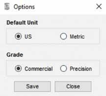
Figure 1
Tolerance Grade Default Setting
The user is now able to set the default for Tolerance Grade to either Commercial or Precision.
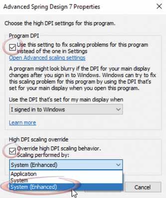
Fix for Scaling problems
Microsoft has introduced a setting to fix scaling problems for users with high DPI settings. This fix will allow the user to continue to use high DPI settings without causing ASD forms to be cut off.
To activate this setting (Figure 2): 1. Locate the ASD7.exe file on your local hard drive. Typically this is found in the folder “C:\Program Files (x86)\
UTS\Advanced Spring Design 7 \” 2. Right-click on ASD7.exe and select
“Properties” 3. Click the “Compatibility” tab 4. Click the “Change high DPI settings” butt 5. a) Check the box “Use this setting to fix scaling problems for this program instead of the one in Settings”
b) Check the box “Override high DPI scaling behavior. Scaling performed by:
c) Select “System (Enhanced)” from the dropdown box
(Figure 3) 6. Click “OK” 7. Click “OK”


Figure 2 Figure 3