2 minute read
General

from Hyster C299 (H170FT, F175FT36, F190FT) Internal Combustion Engine Trucks Service Repair Manual
by amanda

This section has the description and repair procedures for the steering axle.
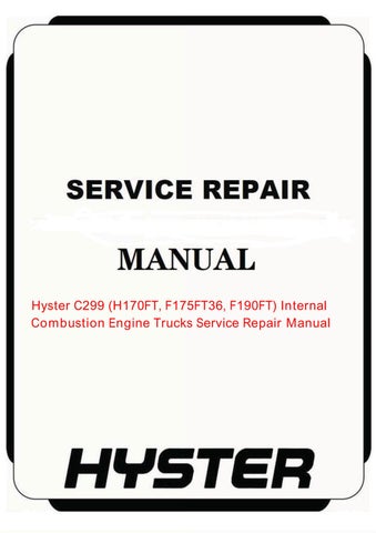
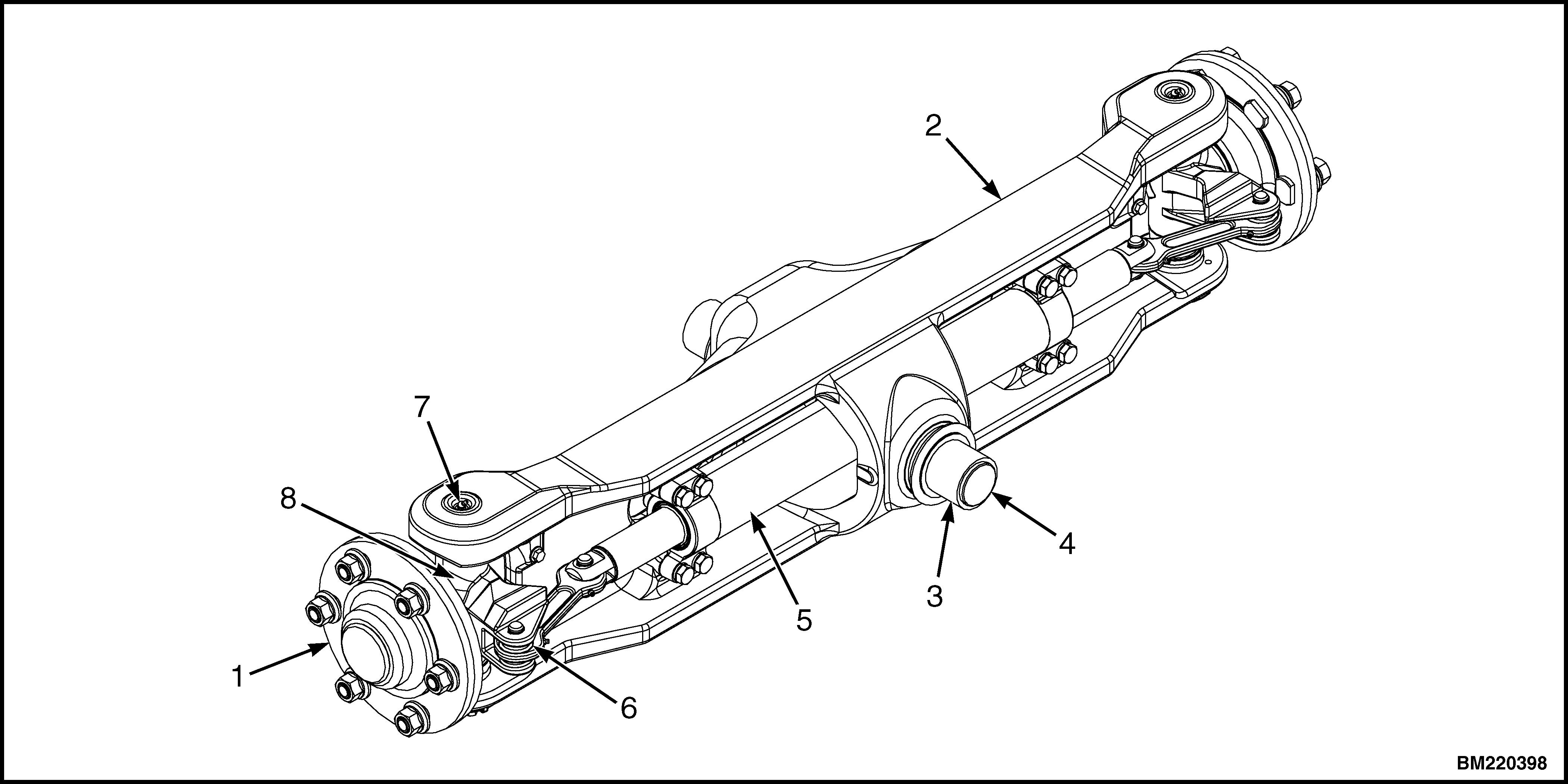
The steering axle assembly includes an axle frame, steering cylinder, and two spindle and hub assemblies. See Figure 1. The steering axle is articulated and is connected to the frame with two mounting plates and four capscrews and washers. See Figure 2.
Advertisement
The end caps of the steering cylinder are also the mounts for the cylinder and are held to the shell by the mount capscrews. There are O-rings, seals, and wipers in the end caps to seal the caps to the shell and rod. The ends of the piston rod extend from both ends of the cylinder. A single piston and the seal are at the center of the rod. Oil pressure on one side of the piston moves the piston in the bore. The piston pushes an equal amount of oil from the opposite side of the cylinder.
When the piston reaches the end of the stroke, a relief valve in the steering circuit controls the oil pressure. The tie rods that connect the spindle arms to the cylinder are not adjustable. See Figure 1.
Each spindle turns on two tapered roller bearings in mounts in the axle frame. The preload on the bearings is controlled by shims at the lower bearing cap.
1. HUB ASSEMBLY 2. AXLE FRAME 3. BUSHING 4. STUB SHAFT 5. STEERING CYLINDER 6. TIE ROD 7. LUBE FITTING 8. SPINDLE
Figure 1. Steering Axle Arrangement
The wheels rotate on two tapered roller bearings and are held on the spindles by a castle nut. The bearing preload of the wheels is adjusted by the castle nut. The grease seals protect the bearings from dirt and water. Wear sleeves protect the hub from wear by the seals.
For information on performing regular maintenance and service on the steering axle, see service manual
Periodic Maintenance 8000SRM1957 for lift truck models • H6.0-7.0FT (H135-155FT) (L006) Periodic Maintenance 8000SRM1959 for lift truck models • H8.0FT, H8.0FT9, H9.0FT (H170FT, H175FT36, H190FT) (C299)
For information related to lift truck capacities and specifications, see service manual
Capacities and Specifications 8000SRM1958 for lift truck models • H6.0-7.0FT (H135-155FT) (L006)
Capacities and Specifications 8000SRM1960 for lift truck models • H8.0FT, H8.0FT9, H9.0FT (H170FT, H175FT36, H190FT) (C299)
1. CAPSCREW AND WASHER 2. MOUNTING PLATE 3. FRAME 4. STEERING AXLE 5. STUB SHAFT AND BUSHING