1 minute read
Checks, Lift Trucks Manufactured After August, 2012 And Equipped With Fork Positioner


Table 1. Fork Tip Alignment
Fork Tip Alignment Specifications Standard Fork
Advertisement
Lengths Maximum Fork Tip Difference1
mm (in.) mm (in.)
914 (36) 27 (1.08) 1067 (42) 32 (1.26) 1219 (48) 37 (1.44) 1372 (54) 41 (1.62) 1524 (60) 46 (1.80) 1829 (72) 55 (2.16) 1Difference of alignment between fork tips must be no more than 3% of the total fork length.
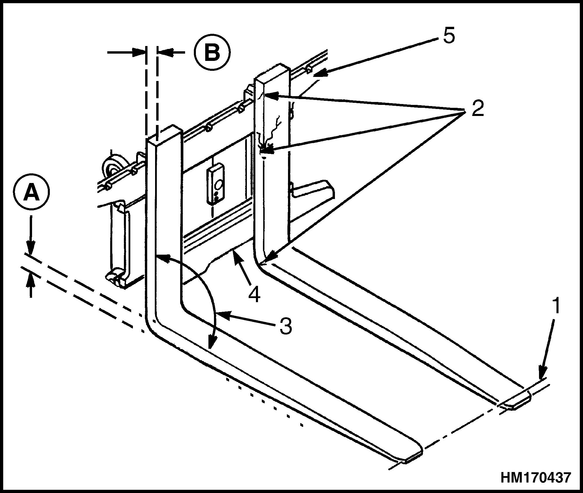
A. HEEL OF FORK (MUST BE 90% OF DIMENSION B) B. ORIGINAL FORK THICKNESS (DIMENSION B) 1. TIP ALIGNMENT (MUST BE WITHIN 3% OF FORK LENGTH) 2. CRACKS 3. MAXIMUM ANGLE 93° 4. FORK REMOVAL NOTCH 5. CARRIAGE
Figure 8. Fork Check
3. Check that the bottom of each fork is not excessively worn.
4. Check for smooth and proper operation of the fork lock pins. Repair or replace any damaged or broken fork lock pins or components and lubricate, as necessary. See Figure 4.
CHECKS, LIFT TRUCKS MANUFACTURED AFTER AUGUST, 2012 AND EQUIPPED WITH FORK POSITIONER
WARNING
Never repair damaged forks by heating or welding. Forks are made of tempered steel using special procedures. Always replace damaged forks as a pair.
1. Inspect forks for cracks and wear.
2. Check alignment of fork tips. Difference in height of fork tips must be less than three percent of fork length. See Table 2 and Figure 9.
Some applications may require closer alignment. If forks DO NOT meet specification they both must be replaced.
3. Check that the bottom of each fork is not excessively worn.
Table 2. Fork Tip Alignment
Fork Tip Alignment Specifications Standard Fork
Lengths Maximum Fork Tip Difference1
mm (in.) mm (in.)
1219 (48) 37 (1.44) 1981 (78) 59 (2.32) 1Difference of alignment between fork tips must be no more than 3% of the total fork length.


