Energy in transition
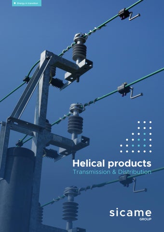
Helical products
Transmission & Distribution
1
About us Sicame Group is one of the key players in the electrical equipment business worldwide. It has been able to adapt and develop to support the continuous evolution of electricity infrastructure in France and around the world, and become the largest independent entity in its sector. A true player in the energy transition, it offers its customers new products and services to improve energy efficiency, deal with environmental risks and support the development of electric vehicle and solar power plant markets.
70
567 M€
3,600
years of worldwide success
2023 turnover
employees
Transmission
Distribution
Our fields of activity
With decades of history and recognized expertise, our Transmission and Distribution division is specialized in designing, manufacturing and producing comprehensive ranges of products and plays a pivotal role in the supply of power across the world. Our T&D team engineers, planners and environmental specialists is actively working on the cornerstones of a 21stcentury energy grid economy. By reducing the electricity sector’s carbon emissions, we contribute to realising the promise of a sustainable future.
Electromobility
Renewables
Sicame Group is specialised in products and services related to transmission and distribution of electrical energy, renewables, electro-mobility, safety equipment and industrial applications. Commercial & Industrial
OEM
Services
5 continents 26 countries 50 companies around the world Products distributed in 157 countries
2
V
3
Design concept Helical wire design
Layer direction
Designs of helical wires are an optimum combination of conductor diameter, material used, inside diameter, pitch, lay direction, number of rods and length applied.
In order to obtain maximum efficiency it is essential that products are manufactured with an identical layer direction to the outer layer of conductor or strand on which they are applied.
The inside diameter of the helical fitting is less than the outer diameter of the conductor so that each rod exerts a uniform low radial pressure inherent with spring tempered material.
Inside diameter
Pitch Rod diameter
Z: Left hand layer
Number of rods per set
Aspect of the products
After application of the correct number of rods, a slight gap between the rods should be present, Study the 3 following examples,
Our products are presented under the following forms: ● Set of rods: armor rods, line guard
Example 1: Excellent application.
● Sub sets made of glued rods: tie rods
Example 2: Satisfactory, but may lead to applying an extra, unneeded rod. Extra rod produces bridging condition and eventual rod abrasion.
● Sub sets made of glued and gritted rods: repair splices, distribution grip, deadends and service grip Set of rods
Example 3: Extra rod, expanded tube condition, affords little protection, allows severe abrasion and other conductor damage. If undecided about adding an extra rod; leave it out. Rods 12
12 2
9 8 7
5 6
Rods
13
3
10
4
9
Gritted sub-sets rods
13
12 1
11
10
Sub-sets of rods
Rods
1
11
1
11 2
2
10 3
Conductor
3
9 4 8 7
6
5
Conductor
4
8 7
6
5
End finish Depending on the voltage, ends of the individual rods may either chamfered, ball ended or EHV (Extra High Voltage) ended. EHV end finish is generally only required if transmission lines voltage is more than 330 kV.
Conductor
Loop configuration Open looped and twisted looped deadends can be provided.
Twisted looped Chamfered
4
S: Right hand layer
Ball ended
Open looped
EHV ended
5
Transmission grid OPGW, ADSS and Armor Rods
Armor rod - spacer damper
Armor rod - vibration damper
OPGW suspension set
OPGW deadend
Armor splice Long span suspension
ADDS long span deadend
6
Plastic spiral vibration damper
7
Distribution grid Tie’s and deadend
Angle tie Top tie
Double side tie
Cross over tie Distribution Service deadend
Double support tie
Guy grip deadend
ADSS deadend
8
ADSS suspension tie
9
Armor rods Armor rods length should be modified for specific installation Armor rods are used in protecting conductors at suspension points, stockbridge vibration dampers, and angles up to 30°. Armor rods help decrease strains and extend conductor life, especially in severe conditions. Advantages ● Recommended for protection at suspension points and angles up to 30° ● Prevents conductor bending ● Decreases mechanical strains caused by wind, tension, and vibration ● Extends the life of conductors, particularly in severe conditions
Armor grip suspension
D
Armor rods for AAC/AAAC/ACSR/ACAR
Line guards Line guards offer safe and economical protection for rigid and overhead line conductors. Advantages ● Lightweight design ● Safe and economical protection for conductors ● Effective against friction and short-circuit damage at attachment or suspension points ● Reduces radio and television interference compared to other guard fittings
Transmission D Φ
Line guards for AAC/AAAC/ACSR/ACAR
10
11
OPGW & ADSS
Repair sleeves Application
Armor grip suspension set for OPGW-Single armor grip suspension set
The repair sleeve restores the full conductivity and mechanical strength to the conductor(homogeneous and ACSR) where the damage does not exceed 33% of the outer layer and when located outside the support area.
Armor grip suspension
Application The armor grip suspension is used for the movable suspension of conductors and optical fiber aerial cables on suspension towers. 1
D
2
Repair sleeves for AAC/AAAC/ACSR/ACAR
3
4
Φ
5
1. 2. 3. 4. 5. 6.
Shackle Housing Inserts Armor rods Parallel groove clamp Ground cable
6
Helical deadend for OPGW - Single helical deadend set
Armor splices Armor splices are recommended for repairing severely damaged conductors at suspension points. They are especially useful in the support zone and positioned not less than 150 mm from existing armor rods or lineguards to improve frictional contact. Advantages ● Restores electrical characteristics of ACSR and homogeneous conductors
Application Helical deadends are ideally suited for the full tensioning of OPGW. Deadends are composed of five or more preassembled helical rods which are covered with small-grained sand on the inside to improve the frictional contact. The loop of the deadend is protected from abrasion by means of a thimble. The deformation of the cable is omitted as the radial compression is distributed over a large contact area. 5
● Reconstitutes mechanical properties, especially for aluminum strands of ACSR
4
2
3
1
● Positioned to improve frictional contact ● Distributes radial compression over a large contact area, minimizing cable deformation
D
OPGW
6
Armor splices for AAC/AAAC/ACSR/ACAR 7
Φ
1. 2.
Reinforcing rods Helical deadend
3. 4.
5. 6.
Shackle Parallel groove clamp
7.
Ground cable
Line splices
Armor grip suspension set for ADSS - For short span<150 m
Restorative repair
Application
Line splices restore original conductivity and full mechanical strength to homogeneous conductors.
The helical rods are designed for ADSS telecommunication system. They are used for span lengths up to 150 m approximately.
For ACSR conductors, they will hold the original conductivity and full mechanical characteristics of the outer aluminum strands.
The suspension rods with the helical loop are the supporting accessory. The shorter and straight reinforcing rods are only used for stiffening the area around the suspension point. The loop of the fitting is stabilized and protected against abrasion with a ring type thimble.
2
1
D
3
Line splices for AAC/AAAC/ACSR/ACAR ADSS
Φ
1.
12
Thimble Turn buckle
Suspension rods
2.
Reinforcing rods
3.
Round thimble
13
Armor grip suspension set for ADSS for short span<220 m
Helical deadends for ADSS for medium span<300 m
Application
Application
The helical rods are designed for ADSS telecommunication system. They are used for span lengths up to 220 m approximately. The suspension rods with the helical loop are the supporting accessory. The straight reinforcing rods are used for stiffening the area around the suspension point. The loop of the fitting is stabilized and protected against abrasion with a ring type thimble.
Helical deadends are ideally suited for the full tensioning of ADSS. Deadends are composed of five or more pre-assembled helical rods which are covered with small-grained sand on the inside to improve the frictional contact. The loop of the deadend is protected from abrasion by means of a thimble. The deformation of the cable is omitted as the radial compression is distributed over a large contact area.
3 1
2
ADSS
1.
Suspension rods
2.
Reinforcing rods
3.
1
Round thimble
2
4
3
5
ADSS
Armor grip suspension set for ADSS for long and medium span<600 m Application The armor grip suspension is used for the movable suspension of self supporting optical fibre aerial cable on suspension towers. 1 5
rip or g
2
4
Arm
3
et ion s
ens
susp
g
sin Hou
ADSS 1.
Shackle
2.
Extension link
3.
Housing
4.
Inserts
5.
Armor-rods
Helical deadends for ADSS for long span<600 m Application Helical deadends are ideally suited for the full tensioning of ADSS. Deadends are composed of five or more preassembled helical rods which are covered with small-grained sand on the inside to improve the frictional contact. The loop of the deadend is protected from abrasion by means of a thimble. The deformation of the cable is omitted as the radial compression is distributed over a large contact area. 1
Helical deadends for ADSS for short span<150 m Application These deadends are designed for the full tensioning of ADSS cables in short span lengths up to 150 m or 10 KN of RTS. The loop of the deadend can be protected against abrasion by a thimble.
1. 2. 3.
Shackle Extension link Thimble
4. 5.
Helical deadend Reinforcing rods
2
4
3
5
ADSS
Tension and suspension for ADSS round drop cable for short span<50 m Application ● ● ●
Helical deadends for ADSS for short span<220 m
Suspension set for ADSS round drop cable span < 50 m Maximum vertical load: 3000 N Minimum slipping load: 200 N
Application Helical deadends are ideally suited for the full tensioning of ADSS. Deadends are composed of five or more preassembled helical rods which are covered with small-grained sand on the inside to improve the frictional contact. The loop of the deadend is protected from abrasion by means of a thimble. The deformation of the cable is omitted as the radial compression is distributed over a large contact area. 1
2
3
4
5
3
2 1 1. 2. 3.
14
1.
Shackle
2.
Extension link
3.
Thimble
4.
Helical deadend
5.
Reinforcing rods
Suspension rods Housing AXIS
15
Overhead distribution lines Distribution deadends for bare cables Deadends are designed to hold bare homogeneous cables in distribution construction. Mechanical strength of these deadends is superior to the one of homogeneous cables. But, for steel-core cables the strength is approx 95% of the breaking load of the aluminum strands. This products are manufactured with aluminum covered steel for ACSR and homogeneous conductors, with copper covered steel for copper conductors. These distribution deadends must be used with a clevis thimble and insulators, with smooth contoured surfaces, adequate groove widths and loop diameters. Open looped
Deadend
Bare cables
Service grip deadends for bare cables Service grip deadend are designed to secure conductors for house service connections. Service grip deadend are recommended for house service by reason of minimal length, maximum economy and neat appearance. Service grip deadend is a limited tension deadend: for bare homogeneous messenger conductors (aluminum, aluminum alloy and copper) the holding strength of grip is about 80~90% of the rated conductor strength. With ACSR-AACSR conductors, the holding strength does not exceed 40~65% of the rated strength. Service grip deadends are manufactured with aluminum covered steel for AAC, AAAC and ACSR and copper covered steel for copper conductors.
Top ties Distribution ties are designed for securing conductors in the top groove of rigid insulators vertically mounted. This specific distribution tie provides perfect resistance to mechanical strain under all types of motion including aeolian vibration, galloping and sway. Distribution tie design takes into account a tie pad to protect the bare conductor from abrasion at the conductor insulator interface. Tie pads are not required with covered conductors. This product is manufactured with the same grade material as the conductor to which it is applied.
Distribution
Top ties for bare cables
16
17
Side ties Side ties are designed for securing conductors in the side groove of insulators. Both vertically or horizontally mounted. They eliminate fatigue and wear problems on conductors. Its design takes into account a tie pad to protect the bare conductor from abrasion at the conductor-insulator interface. Tie pads are not required with insulated conductors. This product is manufactured with aluminum covered steel for ACSR and homogeneous conductors, with copper covered steel for copper conductors and galvanized steel for direct application on insulated conductors.
Guy-grip deadends
Cross over ties
Double side ties Double side ties are designed for securing conductors in the side groove of insulators on double cross arms where the line angle is between 0°~80°. They eliminate fatigue and wear problems on conductors. Its design takes into account a tie pad to protect the bare conductor from abrasion at the conductor-insulator interface. This product is manufactured with aluminum covered steel for ACSR and homogeneous conductors, with copper covered steel for copper conductors.
MVCC MV covered conductor network is mainly used in urban or outer-urban zones or forest areas. Mainly used conductors: AAC/AAAC/ACSR/copper, single or double insulated/HDPE/XLPE. There are various types of conductors on MVCC networks, each of them with its own technology and cross-section. Users are advised to check compatibility of the accessory with the cable used. Our products range covers majority of conductor sections & types. Our accessories have been tested and approved by our customers for many years.
Angle ties Angle ties are designed for securing conductors in the side groove of single vertical mounted insulators where the line angle is between 20°~60°. They eliminate fatigue and wear problems on conductors. Its design takes into account a tie pad to protect the bare conductor from abrasion at the conductor-insulator interface. This product is manufactured with aluminum covered steel for ACSR and homogeneous conductors, with copper covered steel for copper conductors.
18
Twin ties Twin ties are designed for securing covered conductors in the top groove of rigid insulators vertically mounted. This specific twin tie provides perfect resistance to mechanical strain under all types of motion including aeolian vibration, galloping and sway. Well anti-aging properties for the plastic coating.
19
Non metallic helical products
Fig 1
Fig 2
Fig 3
Plastic spiral vibration damper Rigid alignment tie Plastic rigid alignment insulator ties help keep insulators securely in place, preventing them from becoming misaligned or dislodged, which could lead to electrical arcing or mechanical failure.
Advantages ● Vibration reduction
Advantages
● Increased lifespan
● Insulator stability
● Improved reliability
● Improved line Performance
● Cost-effectiveness
● Reduced maintenance
● Easy installation
● Corrosion resistance
They can be easily applied during installation or retrofitted onto existing power lines.
● Lightweight and easy to install They can be easily applied during installation or retrofitted onto existing power line insulators.
● For attachment of covered conductors 35 to 240 mm² to pin type insulators ● Easy to install on cable/conductor without any tools ● UV resistant thermoplastic material
* Without optical consideration of the cable. Tensile test to be done with a sample of cable.
20
Plastic spiral vibration dampers are used in overhead power lines to mitigate the effects of wind-induced vibrations. They are typically applied to overhead conductors to reduce the risk of fatigue failure and prolong the lifespan of the conductors.
Span length
Number of PSVD
Anchoring/Suspension
100 - 200
2
Fig 1
201 - 350
4 (2 subsets of 2)
Fig 2
351 - 550
6 (2 subsets of 3)
Fig 3
Construction and installation ● Made of weather and corrosion resistant thermoplastic material ● The helically formed rod has a smaller diameter area for gripping the cable/conductor and a larger diameter area for the damping section ● Ideal for use on: • Bare conductor • Optical ground wire (OPGW) • Covered conductor • Optical fiber cable (OFC) • Overhead shield wire 21
Laboratory testing and Industrial manufacturing processes
More than just a Group Our social commitment, missions & values
All Sicame accessories are tested and comply with international standards.
Laboratories capabilities worldwide Customer intimacy
●• Certified laboratories ●• State of art equipment ●• 3rd party services ●• Expertise ●• University partnership
We are recognized by our customers as a credible and valued global partner by providing solutions to each situation based on our customer’s needs.
Tests and R&D Our transmission & distribution laboratory is assisting both design activities and product verification. In the design stage it is supporting the technical department in its activity of research and development while in the product verification stage all quality control mechanical verifications and tests are carried out including batch acceptance tests.
Innovation by everyone, everywhere In our Group, innovation is everyone’s business.
We can perform also independent tests under accreditation or not for third party (cable manufacturers, utilities …). Test bench systems have the flexibility to meet specific requirements.
Components mechanical tests:
Are performed at our laboratories worldwide that are fully equipped for all kinds of destructive and non-destructive tests.
Engaging with passion
Full scale mechanical tests:
We create an environment which allows all our collaborators to act as entrepreneurs in the Group.
We are also capable of carrying out full scale mechanical tests in independent and accredited laboratories so as to verify the real mechanical behavior of the full strings.
Manufacturing Manufacturing activities are carried out in our factories directly or through our sub-suppliers and partners within Sicame Group. ●• Manufacturing processes excellence centers ●• Interconnected supply chain among business unit network ●• Complete manufacturing processes inside business unit
COFRAC ACCREDITATION ST-ETIENNE LABORATORY
2222
Social responsability We believe that the sustainable development of the company is built through the fair balance between economic performance and respect of the Group’s human dimension.
Team spirit Brought together by a common goal, we develop a close collaboration within and between the teams, based on transparency, trust and respect of our collective and individual identities.
23
24
GBS23TRA0210_Helicoidal ties&spiral_vibration dampers: Photo : Sicame GBS