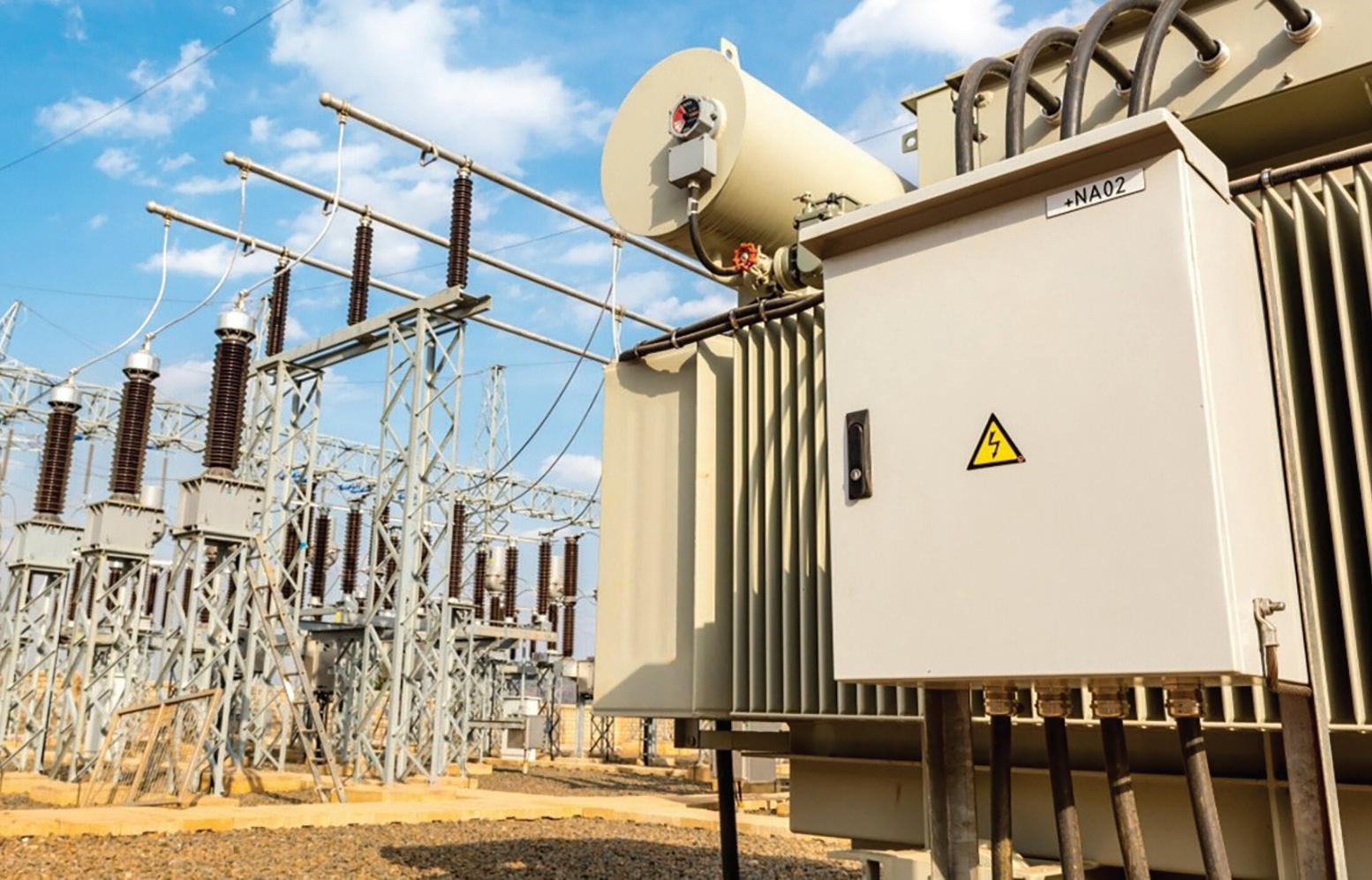
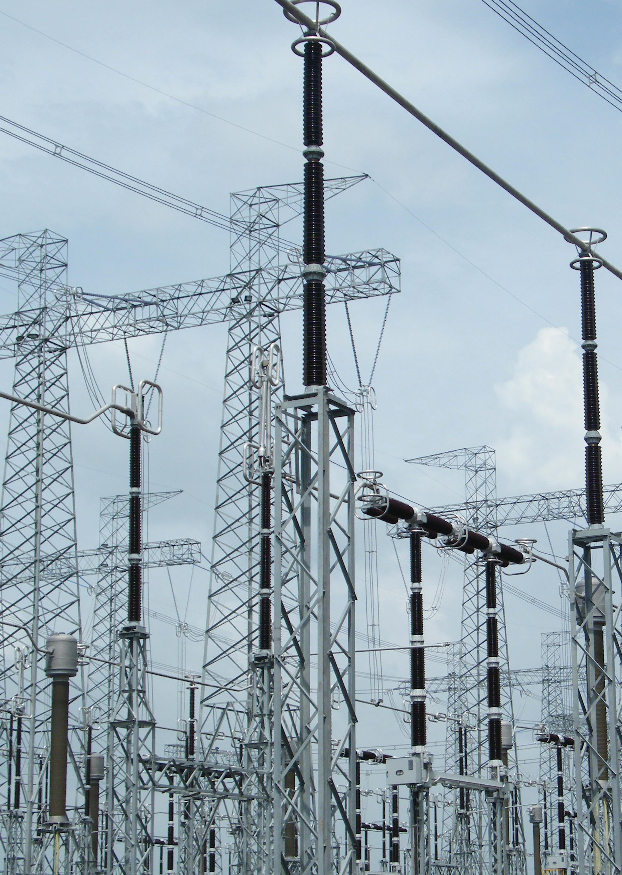
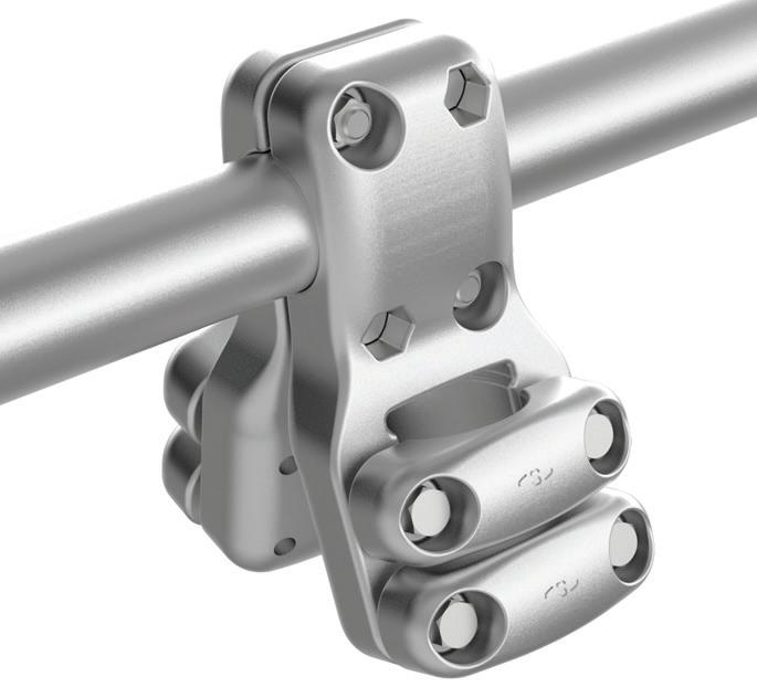
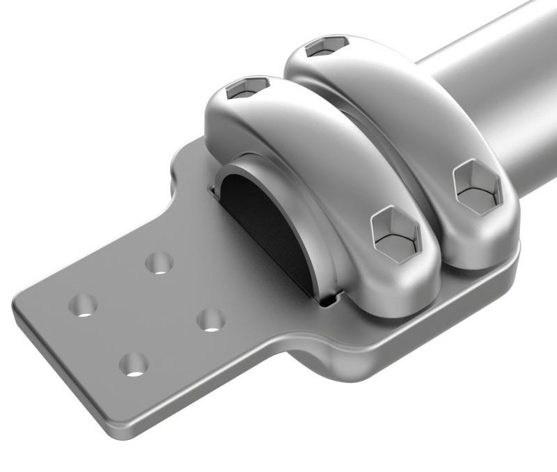
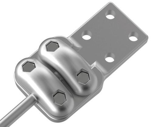
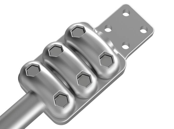
Sicame Group is one of the key players in the electrical equipment business worldwide. It has been able to adapt and develop to support the continuous evolution of electricity infrastructure in France and around the world, and become the largest independent entity in its sector.
A true player in the energy transition, it offers its customers new products and services to improve energy efficiency, deal with environmental risks and support the development of electric vehicle and solar power plant markets.
70
3,600 employees
Our fields of activity
Sicame Group is specialised in products and services related to transmission and distribution of electrical energy, renewables, electro-mobility, safety equipment and industrial applications.
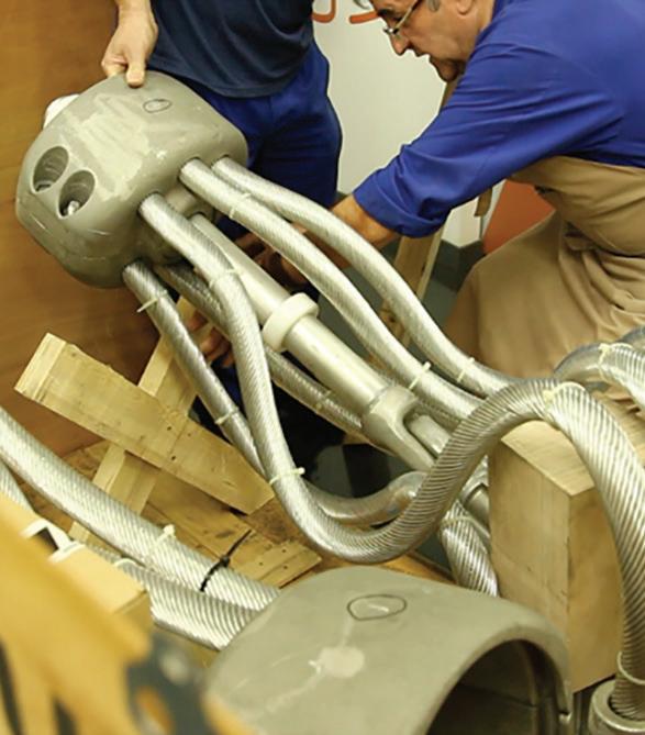
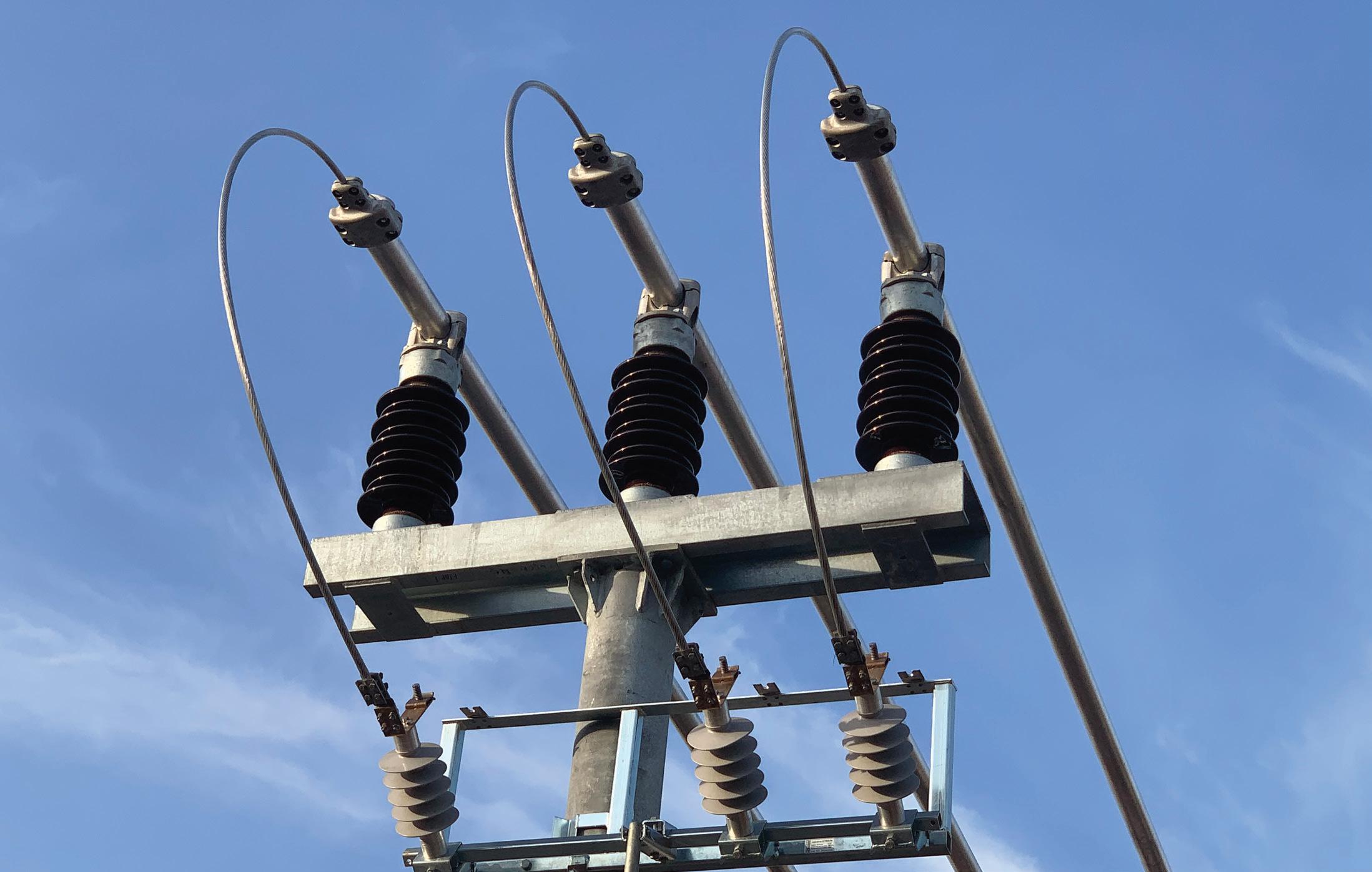
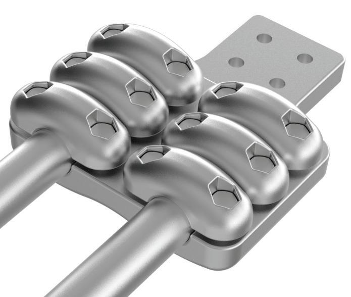
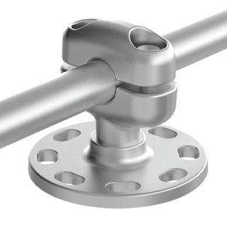
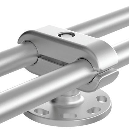
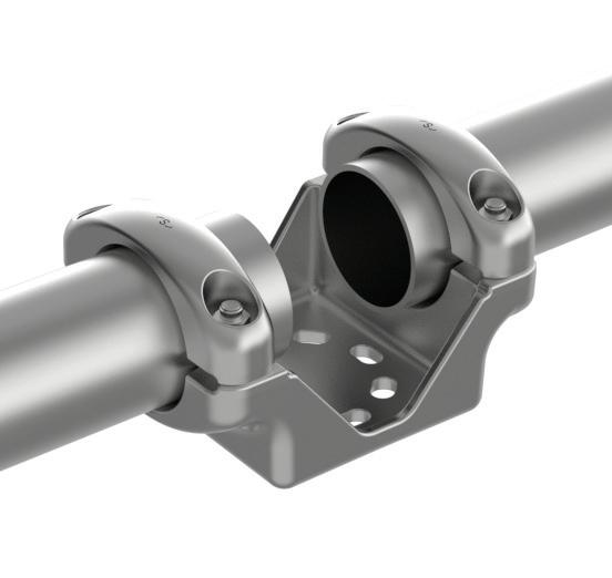
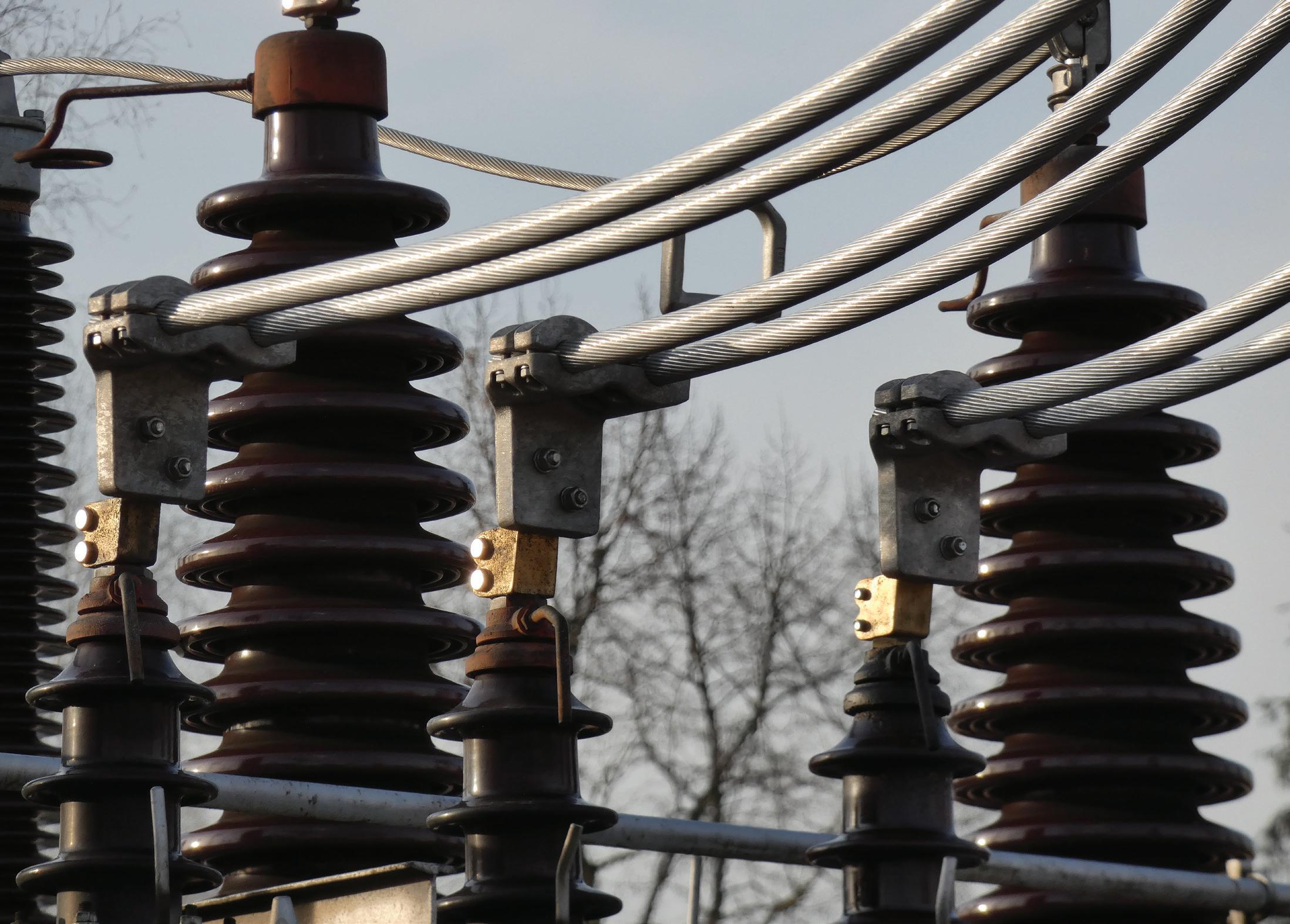
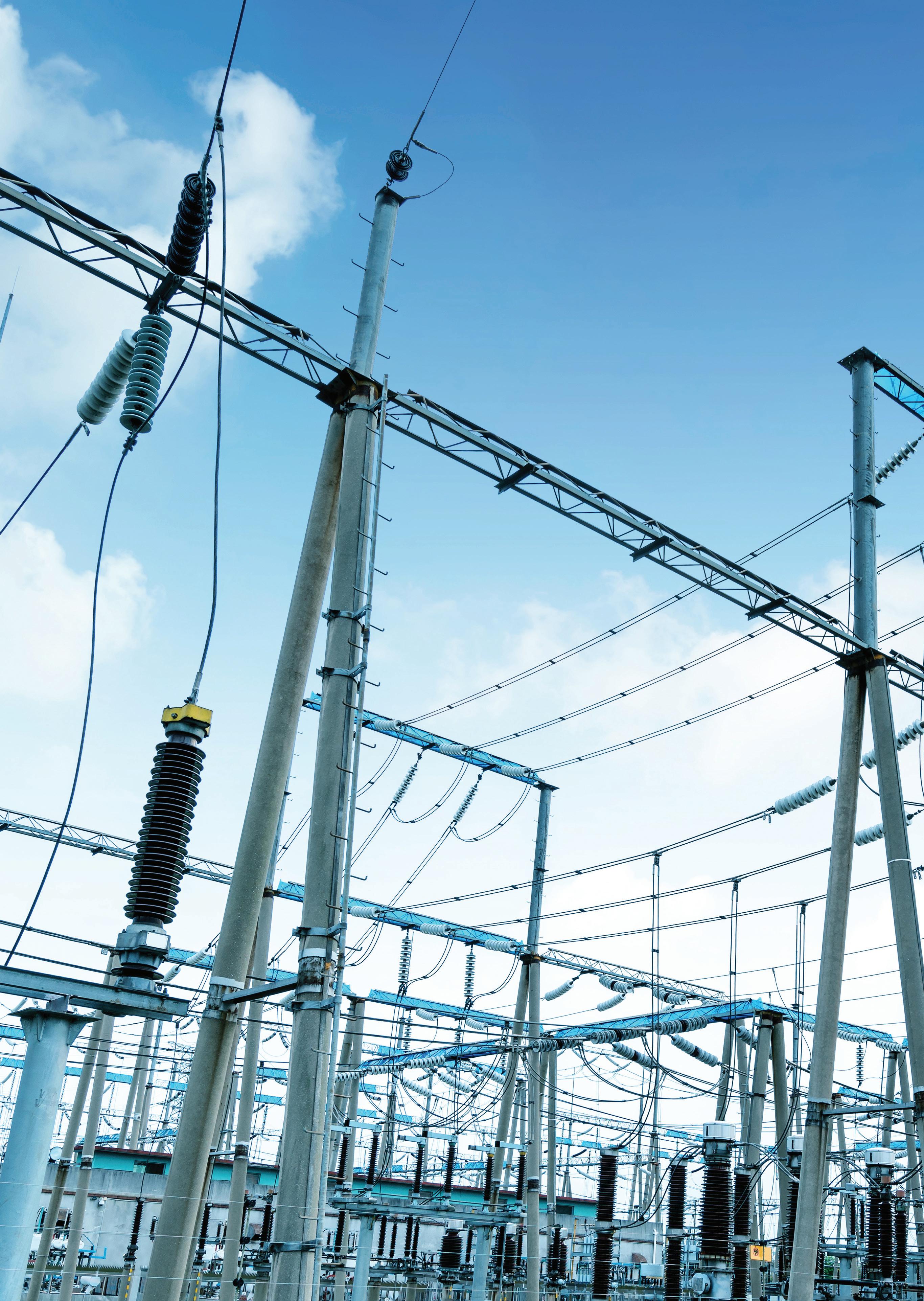
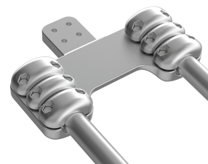
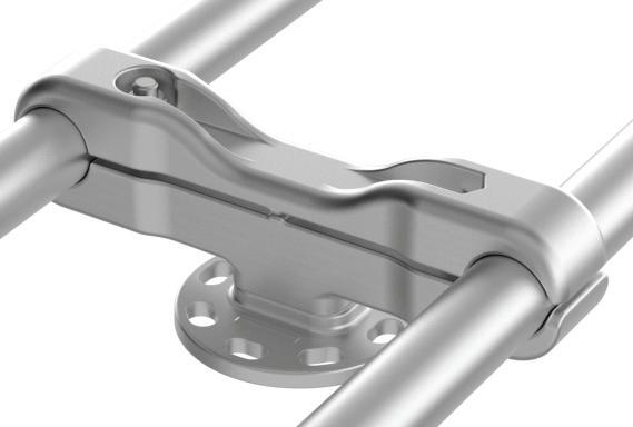
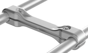
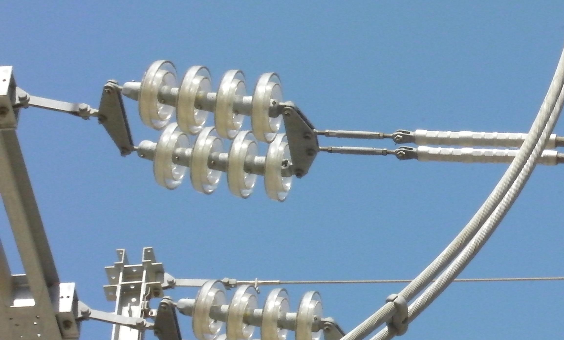
Sicame Group is a recognized world leader specialized in the definition and manufacturing of components, accessories, equipment’s & services for building Transmission and Distribution electrical networks. With decades of background and recognized expertise, Sicame Transmission business unit is specialized in designing, manufacturing and producing comprehensive ranges of Transmission lines and systems connectors, dampening systems, hardware and most advanced substation fitting solutions, adapted to the most technical configurations such as 8-bundle Spacer dampers, UHV HVDC connectors or innovative high temperature conductor accessories.
Sicame Transmission relies on world class brands - renowned and trustworthy in the Transmission realm thanks to unique know-how - giving our customers the best in class solutions. Sicame Transmission is specialized in designing, manufacturing and testing products for High and Extra High Voltage Overhead Transmission Lines.
A century of Engineering Leadership Our Transmission & Substation set of companies carry an unmatched combined know how heritage.
Widest range of tested high voltage components. The combination of our ranges and testing facilities allows for a completely tested thorough HV, EHV and UHV line and system accessories.
Technical introduction
R&D Expertise
Developing the new generation of 1200 kV AC and 800 kV DC
SICAME’s engineering team has acquired internationally recognized expertise in customized substation configuration design, enabling us to provide full technical evaluation for:
• 3D designs
• Laboratory testing
• Thermal simulations
• Antivibration studies
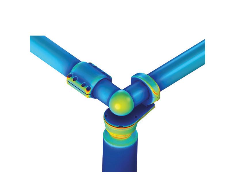
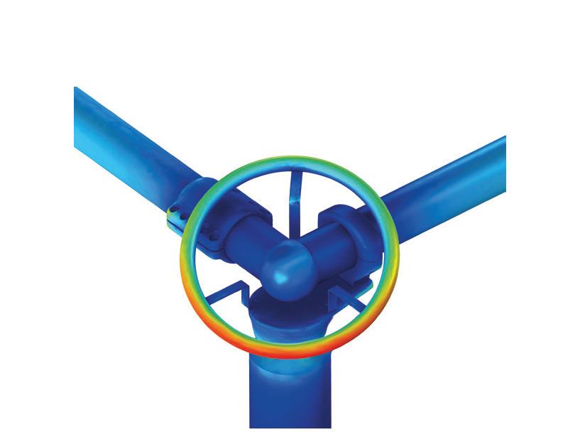
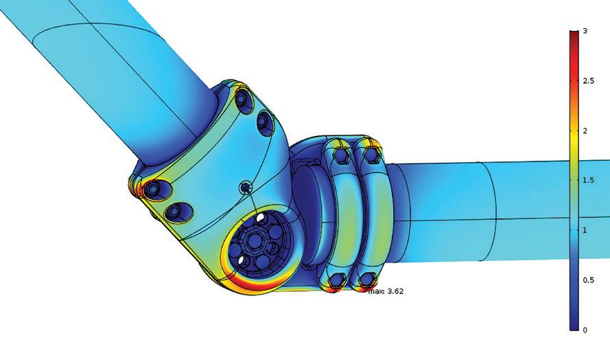
• Corona simulations
Personalized solutions (LSS connectors line for the disconnection in effect. Lighter corona protections, device line to damper vibrations in the substation tubes,...)
Our Research and Development Engineering Teams focus on:
• Identification of UHV performance factors
• Investigation of new materials
• Exploration of new designs
Approvals
Our products meet and are approved by the main international standards IEC, NEMA, ASTM, UL, VDE, AENOR and DIN.
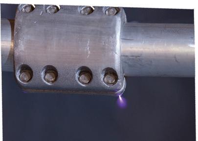
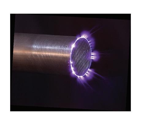
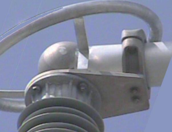
Corona in the base of the support, as expected from corona simulation.
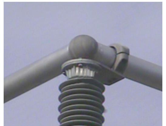
No corona detected, as expected from corona simulation.
High and Ultra High Voltage Research and Development Center
Sicame and the MCIA center (Motion Control and Industrial Applications) collaborate in the creation of the high and ultra high voltage Research and Development center. It is a unique center in Europe because of its characteristics, equipment and facilities. MCIA is an affiliated center of the Polytechnic University of Catalonia, which focuses on research, innovation and product development.
The state-of-the-art center provides the Sicame R&D team with the opportunity to constantly expand its knowledge by conducting several types of tests and simulations, with the aim of offering its customers the most efficient and innovative solutions.
In addition, the company collaborates with the MCIA center and the Polytechnic University of Catalonia, funding several theses to ensure continuous research in HV system applications.
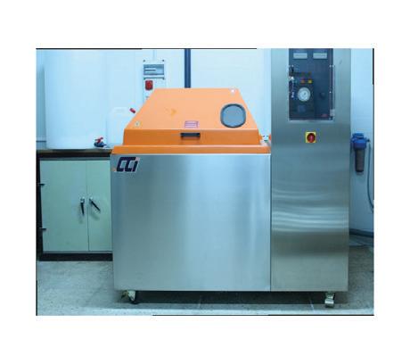
All new developments are tested and validated at the Investigation center and high voltage test through: Electrical tests, Mechanical tests, Chemical and metallographic tests and controls, Outside tests for Corona / RIV, Corrosion tests in salt fog chamber.
Technical specifications
Technical information
Pullout strength test ANSI/NEMA CC1 §2.7-3.2
• The connectors for stranding conductors(s) are designed to withstand the mechanical loads which can be applied on the conductor(s)
• The minimum pullout strength of the connector is a tensile load of 8896 N applied.
• No failure to be observed during the test
Cantilever strength test - ANSI/NEMA CC1 §2.8-3.4
• Support devices are designed to withstand the mechanical loads which can be applied to the supports fixed in structures or post insulators
• The minimum cantilever strength of support is a transverse load of 8896 N is applied
• This mechanical value is representative of the forces applied to the connections in case of short-circuit and external loads, like wind, applied to the bus bar and beard for whole structure system
• No failure to be observed during the test
Torque strength test - ANSI/NEMA CC1 §3.5
• The conductor(s) are assembled in the connector and the bolts are tightened uniformly and alternatively in accordance with their instruction manual (document reference: IICS01), increments until 50% over the nominal torque value is achieved
• No failure to be observed during the test
Temp. Rise test - ANSI/NEMA CC1 §2.6 §3.1
• Connectors must not provoke any temperature rise in a substation circuit and should not transfer any additional heating to other component or equipment of the substation layout
• NEMA CC1 standard criteria’s are as follows: The connectors tested have a temperature rise less than or equal to the hottest connected conductor for the same current
• No damage or failure to be observed during the test
• Included resistance test in the according to IEC 62271-1
Short-circuit test – IEC 62271-1 §6.6
• The connectors are designed to carry-out the short-circuit current that may flow through the conductors on which it is installed
• This short-circuit current must not cause any damage to the connector and neither burn on the contact surfaces nor welding between the parts must occur during the short-circuit
• Included resistance test according IEC 62271-1
Resistance test - IEC 62271-1 §6.4
• This test shows the difference between the electrical resistances of the connector, before and after testing should be less than 20%
• This test can be done in Temperature Rise Test, Short Circuit test and Salt Spay Corrosion Test described in this document
Heat cycle test - ANSI C119.4
• This test consists of checking the stability of the electrical resistance after performing a number of cycles, which depends on the class of the connector
• This stability is achieved if all resistance measurement does not vary by more than ±5% from the average of all the measurements at specified intervals during the course of the test
• According IEC 62271-1 neither Positive Corona spark nor light are observed on the surface of the products with naked eyes at the nominal voltage equal to Un=1.1xUr/√3 where Un: Phase-ground voltage, Ur: Phase-to-Phase Voltage
• The maximum Radio Interference Voltage (R.I.V.) level is less than 2500 μV (68 dB) at 1.1 xUr/√ 3 with a 300 Ω test circuit impedance. According IEC 61284 the corona extinction (corrected values according to IEC 60060-1) shall exceed the specified minimum corona extinction. The RIV recorded at the specified test voltage shall not exceed the specified maximum RIV
• The curve indicating the RIV against the test voltage shall not present any sudden change between the specified test voltage or conductor voltage gradient and 110 % of the specified test voltage or conductor voltage gradient
Salt spray corrosion test – IEC 60068-2-11
• The connector tested is assembled with the conductor(s) and/or palm required and the whole object is exposed to 500 hours of salt mist in a chamber
• The resistance shall not increase more than 20% between the first and final measurement
Type test reports
Type test applicable standards and specifications:
• SICAME has over 50 years’ experience in design and manufacture of HV and EHV substation connectors
• The Company designs its HV connectors in line with best practice and to internationally recognized industry standards. The standard we adhere to, where appropriate, and that are internationally recognized are:
ANSI/NEMA CC1 Standard:
Electric Power Connection for Substation from American National Standard and National Electrical Manufacturers Association.
IEC Standards:
International standard from the International Electrotechnical Commission.
BS EN Standards:
British Standard European Standard.
* The type test required can be studied
Technical information Standards
Hardware:
We recommend A2-70 or A4-80 in accordance with EN ISO 3506-1 standard.
Characteristics of A2-70 and A4-80 steel in accordance with ISO 3506-1
Our nuts are coated with an anti-seize special treatment.
Description:
This special treatment is a suspension of high-molecular polymers in water. To optimize the lubrication properties this special treatment contains specially selected PTFE. The treatment is used as a coating agent and develops this a well adhering, touch-proof lubricating film after drying. It has been developed to achieve define low friction coefficients with a minimum variation range.
Field of application:
This special treatment is used for mass part lubrication. A typical application example is the coating of stainless-steel screws/bolts and nuts, self-tapping or self-forming screws, rivets, sheet-metal screws, and chipboard screws.
Aluminium:
EN 1706 Aluminium and aluminium alloys. Castings. Chemical composition and mechanical characteristics. EN ISO 6892-1 Metallic materials. Tensile test. Part 1: Test method (at room temperature). ISO 8062 Dimensional tolerances for castings.
Aluminium alloy EN 1706 AC-42100
Aluminium alloy EN 1706 AC-42100
Mechanical properties of the alloy casted in sand for separately cast test bar
aluminium alloy EN 1706 AC-42100
conductivity properties of the alloy casted in sand for separately cast test bar
Material Electrical conductivity measured at 20ºC [MS/m] [1/μΩm] Thermal conductivity [W/mK] EN 1706 AC-42100 20÷27
Copper:
EN 1982 Copper and Copper alloys.
EN ISO 6892-1 Metallic materials. Tensile test. Part 1: Test method (at room temperature).
ISO 8062 Dimensional tolerances for castings.
Alloy and chemical properties and castings:
Numeric
Alloy and mechanical properties:
1N/mm2 = 1MPa
Correlation studies on various existing connector lines, as well as mechanical and electrical engineering considerations in the early seventies, resulted in the establishing of a few simple design rules. Basic idea for all our connectors range is that the connector, at full load, has to run cooler as the conductor(s) to be connected. In order to guarantee this, these rules were applied to shape the connectors lines. Hereafter we will set these basic design rules and describe in more detail the various peculiarities of the designs.
Contact force:
It is well established that the contact resistance of a mechanical connection depends upon the contact force between the surfaces in contact (and not upon contact pressure). As a result of various correlation studies, as well as from laboratory tests it was decided to link the contact force to the amperage of the connection.
A simple rule was set: F=k*I
F : Contact Force ( N ) - I : Current ( A ) - K : constant ( N/A)
For the constant k, a minimum value of 40 Newton Ampere is chosen
Contact surface
The Aluminum material has the propensity to undergo plastic (permanent) deformation when submitted to stress (pressure or traction). This permanent deformation is called “cold flow” and it depends upon pressure, temperature and time.
Studies during the many years of experience, as well taking physical properties in consideration, has led to the definition for the maximum contact force (N/mm). At every specific temperature, there exists a threshold pressure, which is such that up to this limit, there is practically no cold flow. At 110°C, this limit is in the vicinity of 27 N/mm. This is the maximum limit contact pressure adopted for the design of this connector line, which was chosen as the highest steady-state temperature of an Aluminium connection. A short period of overheating during fault currents do not adversely affect a well-designed connection.
Exceeding the maximum force or temperature for a long period of time it will lead to cold flow and loss of the connection quality.
Amperage
Studies during the many years of experience , as well taking physical properties in consideration, has lead to the definition for the allowed maximum Amperage per mm2 is < 0,4 to 1 A / mm2 depending on the type of connector. The dimensioning of the connectors is based on the above mentioned definitions with, as a result, for all product lines a “ run cooler as conductor ” performance as result. This philosophy is established in all variations of our substation connectors.
Connector design
The objective here is to engineer a connector device following the basic rules of adequate force, contact surface and amperage, as given by the rules established previously. A good design should be compact in size. As the force generating mechanism was of major importance, and should be under control, we decided to go for a bolt-nut-washer configuration (no threaded holes).
In order to minimize the possible malfunction of the bolt-nut-washer mechanism, it was also decided to apply the bolting torque to the nut (and not to the bolt head). This is important when tightening on a cylindrical conductor, as there is always a resulting wedge effect, when the components are put under stress. When tightening on the bolt head, the wedge effect would impart to the bolt shaft an alternating bending stress, which is detrimental to the assembly.
Connector grooves to accommodate cables or buses are cast to size of the nominal diameter of the conductor. This diameter is marked on the clamping element. At the end of the groove a cavity is provided for the cutting burs of the conductor ending.
Basic multi-cap design
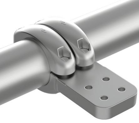
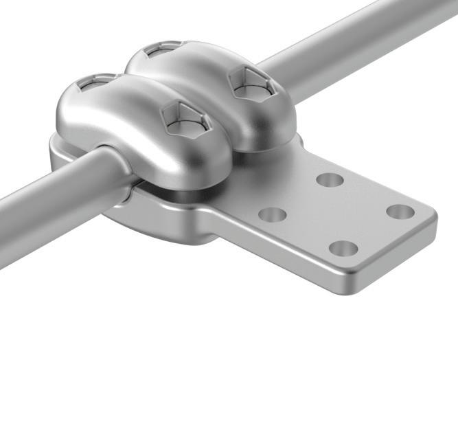
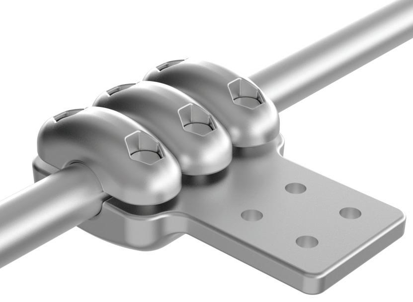
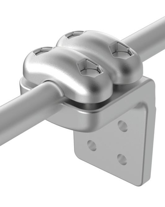
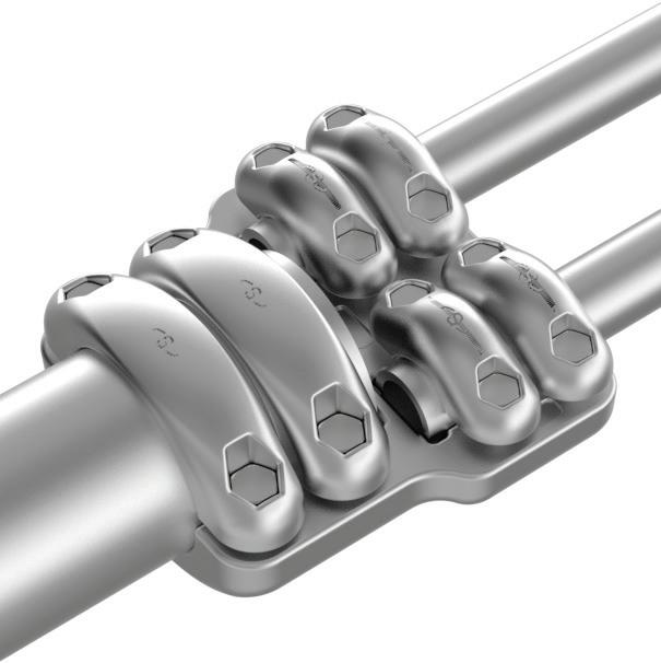
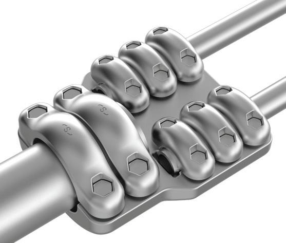
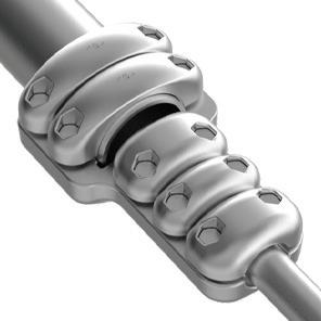
The connector design is based on the multi-cap principle. The body of the connector carries the current, and caps are used to transmit the contact force to the conductor and the body.
A cap carries 2 bolts (and not more). The choice of the “2 bolts per cap” is for mechanical and reliability considerations. Mechanically, each cap transmits its force to a well defined part of the conductor, and guarantees a contact pressure between the conductor and the current carrying body, at the location of the cap.
In a single-cap design, when 6 bolts are used, it may happen that only the extremities of the cap transmit pressure to the conductor (deformed cap). This would result in too high pressure on the extremities, and low pressure at all at the centre of the cap.
Compactness of design
Compactness was achieved by placing the bolt shafts as close as possible to the conductor. Doing so also decreased the bending moment at the centre - line of Cap and Body, giving a second-effect lowering of the bulkiness of the connector.
Preparation of surfaces
Copper (Cu)
Copper conductors do not require any special preparation. Copper oxide is generally broken down by a reasonably low value of contact pressure. Unless the copper is badly oxidized, a good contact can be achieved with very little cleaning (see accessories).
Aluminum (Al)
Oxidation of Aluminum conductors is inevitable. Aluminum oxide is hard, tenacious, and forms a high resistant film. The oxide film forms very rapidly on surfaces exposed to air. Failure to remove this oxide can produce a high electrical resistance and ultimately, a failure of the connection. The steps are:
• Clean the contact surface with a dry stainless steel wire brush (see accessories), until it is bright and clean
• Contact grease should then be applied immediately after cleaning, using another stainless steel wire brush and the surface scraped again through the contact grease. For cables, ensure that the contact grease penetrates between the wires as deeply as possible
• Mark an area 1/4” wider than the connector to brush and coat thoroughly with the contact grease to ensure the contact area is exceeded. Generous application of the contact grease is required
If the connector includes a tinned surface, usually for bimetallic connections, it should not be brushed even if the conductor to connect is copper made. Only Aluminum conductors should be brushed and contact grease applied.
Preparation of bolted connectors
copper (Cu)
Copper bolted connectors do not require any special preparation, except where there is excessive dirt or dust. This can be removed with a clean dry cloth or brush (see accessories).
Aluminum (Al)
For all Aluminum bolted connectors, irrespective of the conductor material, it is essential that contact grease be applied to both surfaces that are in contact. Where both surfaces are Aluminum:
• Surfaces must be cleaned using a dry stainless steel wire brush (see accessories) to remove dirt and dust
• Contact grease should then be applied immediately after cleaning, using another stainless steel wire brush and the surface scraped again through the contact grease
• Ample contact grease must be applied so that it squeezes out of the sides as the final torque to the bolts is applied
If the connector includes a tinned surface, usually for bimetallic connections, it should not be brushed even if the conductor to connect is copper made. Only Aluminum conductors should be brushed and contact grease applied.
Installation for substation connectors
Handing of connectors
• Connectors should be handled with care. Even slight damage to the outer surface of a connector can create corona
• Be particularly careful with cables of expansion connectors, damage of the cable can cause cable breakage as well as local corona.
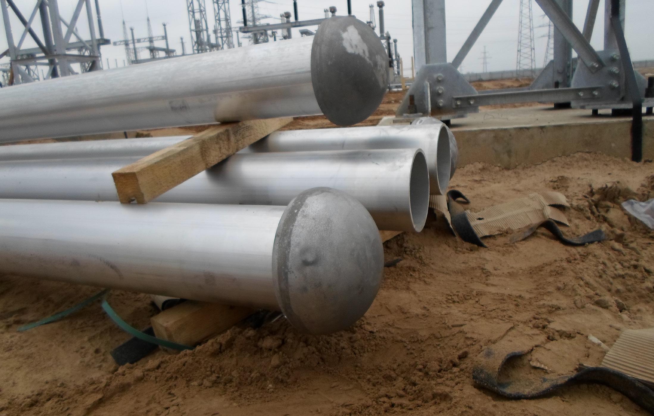
• Avoid dropping or placing the connector on sandy soil. Soil particles can lodge in the threading and damage the bolt. In such cases, the connector should be cleaned with a soft brush.
• Check that the conductor diameter is in the correct range of diameters for the connector being used.
Installation
• Ensure that the conductor is fully inserted into the connector, ensuring it goes to the end of the cavity.
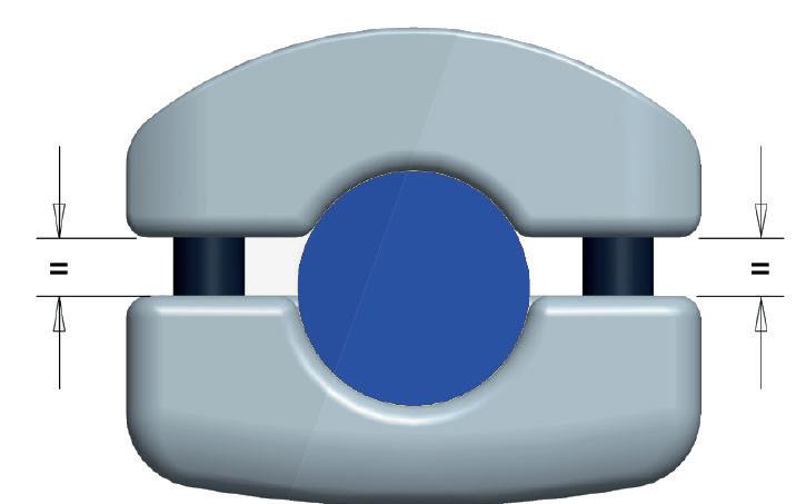
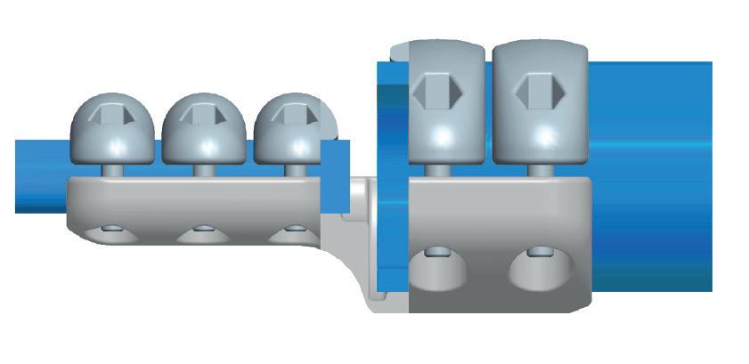
• When assembling make sure the cap is the same distance from both sides. Introduce the screw or nut into the hex hole, depending on the connector and layout, and apply the appropriate torque.
Mechanical joints
Placing the elements
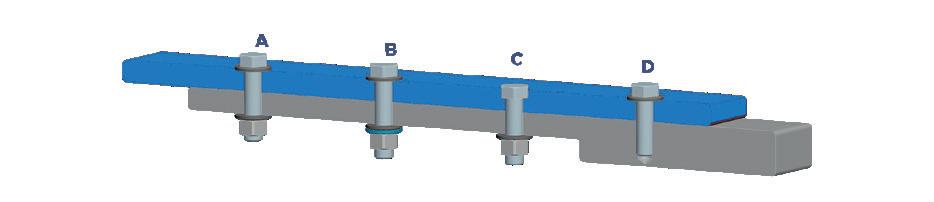
• For mechanical assemblies there are different provisions for securing the various elements
• The basic elements of the assembly are: bolts, washers, washers and nuts
• The following shows the four configurations used
• We do not recommend any change in the standard hardware and installing a hardware not delivered by our company or under our authorization
• In the same way, we do not recommend to install any type of grease for the bolts and nuts assembled in the connectors, since the standard hardware delivered has surface treatment to avoid the gripping in the mechanical union
• These changes without the authorization of our engineers, installing external hardware or using greases, can modify the behavior of the assembly, upsetting the resultant torque and the forces applied
• If in any case is required to use a different hardware and/or a grease in the hardware union, contact us with the technical datasheet of the hardware and/or grease used and will be the technician and engineers of SICAME who warranty the correct installation of the connector
Note: For standard orders, hardware is supplied with surface treatment to avoid gripping problems in these union elements.
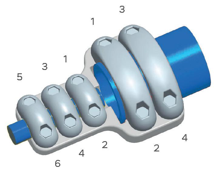
Tightening Sequence
• Initially the screws should be tightened to 60% of the total torque, in the sequence described below
• Subsequently, tighten in the same sequence to the total recommended tightening torque. Always starting at the “end of the conductor” side of the connector and working to the other side of the connector
• We recommend you use the correct torque wrench and sockets
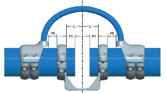
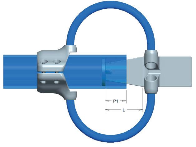
• Expansion connectors allow for expansion and contraction of the conductors as the temperature varies
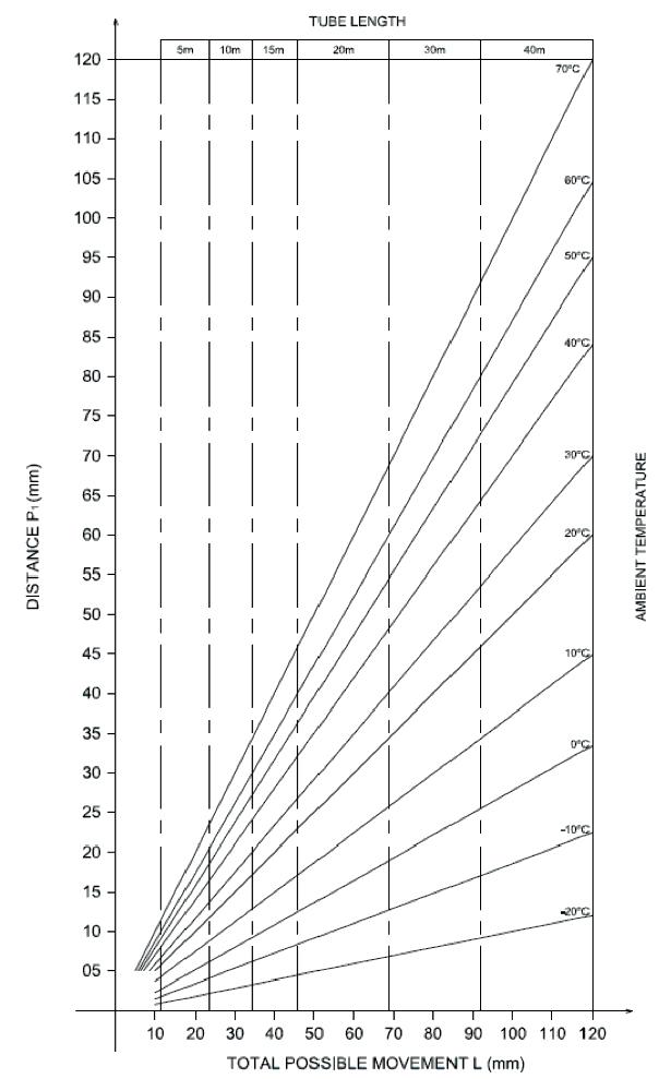
• The Ideal temperature when mounting connectors is 20˚C, for other temperatures, different spacing will be required, these spacing can be determined by following the chart below
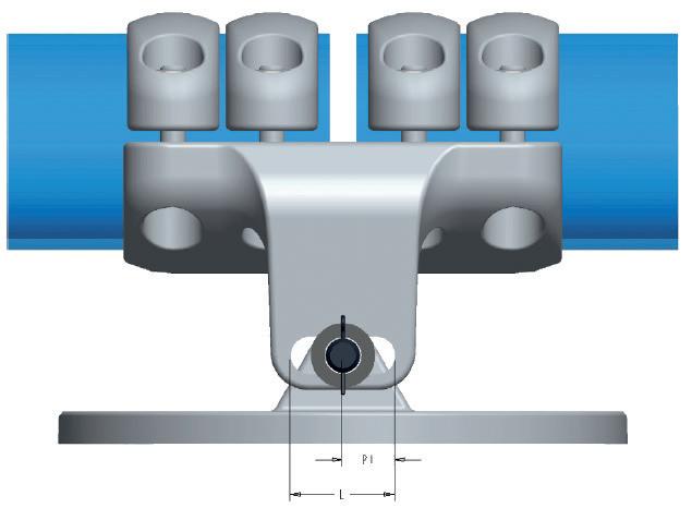
• The dimension (L) is the total possible movement of the connector
• At room temperature, 20˚C, P1 = L / 2 (see graph), while P2 is always the difference in length between L and P1
T˚ ambient 50˚C
L = 60 mm
Look up the graph attached
P1 = 47 mm
P2 = L - P1
P1 = 47 mm P2= 13 mm
P2 = L - P1
Cupal sheets
Cupal sheets are used when bimetallic connections are required, the following installation procedure should be adopted.
• Prepare the surfaces of the conductor and the surface of the sheet of cupal as described previously by treating the surfaces of the foil as that of a connector
• Install the cupal sheet, in the cavity of the connector
• It is important when installing the bimetallic sheets that the copper component is placed at the bottom of the connection, so that the app rent salts corrosion does not affect the conductor / Aluminum connector which could result in accelerated degradation of the contact
Compression connectors
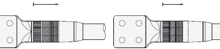
The connectors can be assembled for compression with different forms depending on the requirement, for example, circumferential, hexagonal..
There are two methodologies when crimping:
• Space compression
• Overlap compression (normally 1/3, 1/4, 1/5)
In the first instance, a number of compressions may be applied which are spaced a short distance apart. In the second case, the compressions will overlap by a fraction (see below) of the overall width from the edge of the previous compression.
To affect correct compression the following steps should be taken.
• Banding the cable end before cutting (prevents fraying)
• Thoroughly clean the cable to be connected
• Apply the contact grease (see accessories) to both the conductor and the connector
• Insert the cable into the connector. Remember to remove the ring (band) from the cable end
• Selection and preparation of the tool to perform the compression
• For multiple compressions begin the compression from the cable end of the assembly and ensure you withdraw towards the end of connector for subsequent compressions
Welded connectors
The welding methods recommended are the tungsten inert gas (TIG) and metallic inert gas (MIG), as set out in NEMA CC1 - 2009.
Aluminum 4043 alloy rod shall be used as filler material for Aluminum welded connections between sand castings, extruded Aluminum shapes or cables.
Alternating current shall be used for TIG welding, whereas reversed polarity direct current shall be used for MIG welding. Argon or helium, or a mixture of the two shall be used as shielding gases.
It is highly recommended that the welding operation would be performed by personnel with high skill level in Aluminum welding, because of the difficulty of this process.
Before the welding, it is necessary to:
• Remove oil, oxides, soiling and moisture from the surfaces to be welded. The conductor and power connector welding areas have to be cleaned with a degreasing agent (solvent)
• Sufficient time must be allowed for evaporation of the solvent before welding. Moreover, after solvent cleaning, the oxides shall be removed by brushing with a stainless steel wire brush
• Test the welding machine settings by making a test bead on an Aluminum casting
• Visually inspect the connection to determine proper edge preparation and alignment into the joint
All the melt shall be made with clean metal. During the weld, a smooth and continuous flow of metal with parent metal should be maintained. When several passes are to be made, check the previous pass before laying down the next one, to detect the presence of poor fusion or cracks.
The completed weld must have a smooth finish and indicate good fusion. After the welding it is recommended to accurately clean the weld, to ensure a smooth surface and avoid the corona appearance.
Bimetallic connectors
• For the bimetallic mechanical connectors special care must be taken when handling to ensure that the layer of varnish on the joint between the Aluminum and copper is not damaged
• This varnish is an environmental protection to ensure no corrosion takes place. If for any reason this layer is damaged the bimetallic connector should be replaced
Maintenance
• Connectors delivered by SICAME require no special maintenance
• All products shown in this manual are used in substations and have not been designed for a reinstallation or reopening. In case it is required, please do not hesitate to contact us
• For each connection to be done, it is highly recommended to perform a previous visual inspection prior to installation to ensure products have not been damaged during transportation nor loose pieces are lost, thus requiring an eventual replacement
• Do not hesitate to contact us if you have any queries in this regard. In any case, store your connectors in a dry and clean location before installation
Bonneville Power Administration US
Manitoba hydro Canadá
BC Hydro Canadá
Hydro Quebec Canadá
Hapam
Os Países Baixos
Tennet
Os Países Baixos
RTE
França
ELIA
Bélgica
Transelec
Chile
Engie energia
Chile
ENEL
Chile
National
Reino unido
Scottish Power
Escócia
She
Escócia
ESB
Irlanda
Facebook
Irlanda
Eolicas
Portugal
Hitachi
Suécia
Energinet
Dinamarca
Enel
Itália
Statnett
Noruega
SEC
Arábia Saudita
ARAMCO
Arábia Saudita
EDM
Moçambique
STEG
Tunísia
GECOL
Líbia
Sonelgaz
Argélia
EDEL
Angola
Fingrid
Finlândia
Ge grid
Finlândia
Ukenergo
Ucrânia
Energa
Polônia
Tauron
Polônia
PGE
Polônia
Hyundai
Coréia
NTDC
Paquistão
PLN
Indonésia
SECO
Camboja
PGCIL
Índia
Projects in North America
Celilo converter station is located near the Columbia river, is the northern station of the Pacific DC Intertie, a 1,360 - kilometer HVDC link that connects to the Sylmar converter station in Los Angeles. It transmits electricity from the Pacific Northwest to as many as three million households in the greater Los Angeles area.
The upgraded Celilo station is owned by Bonneville Power Administration.
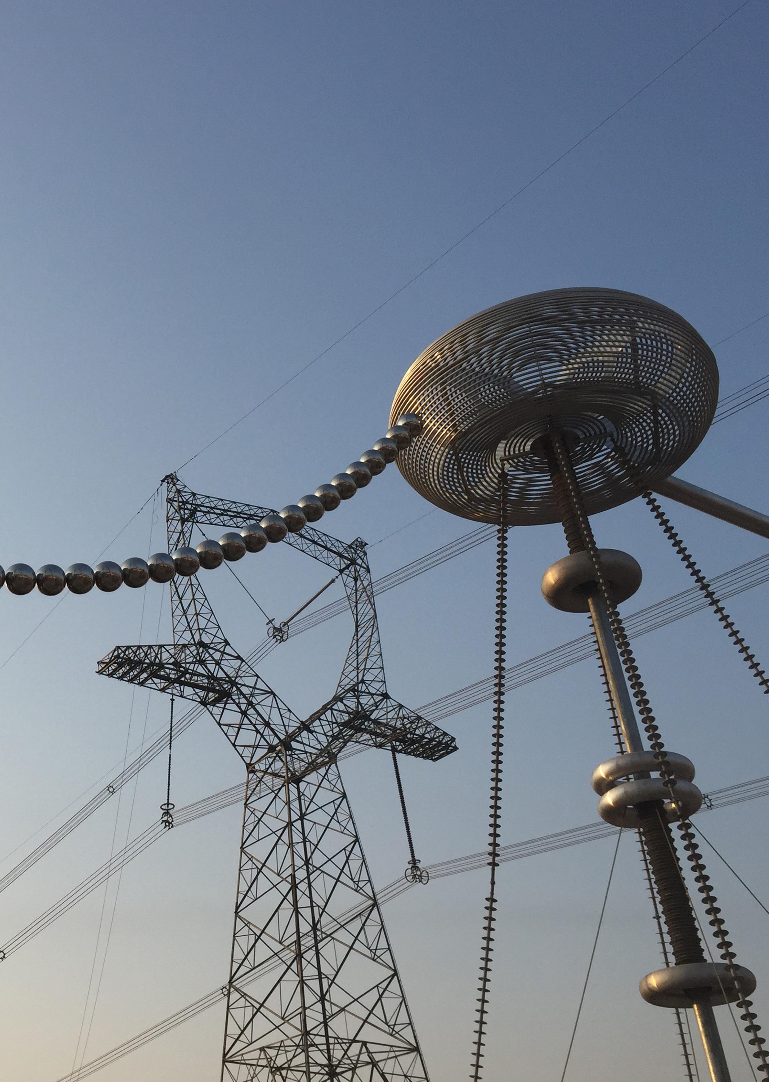
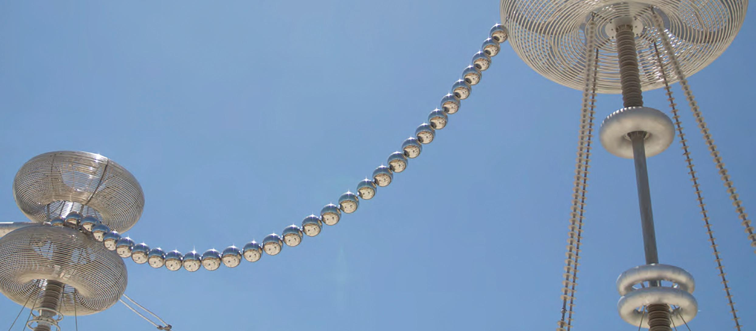
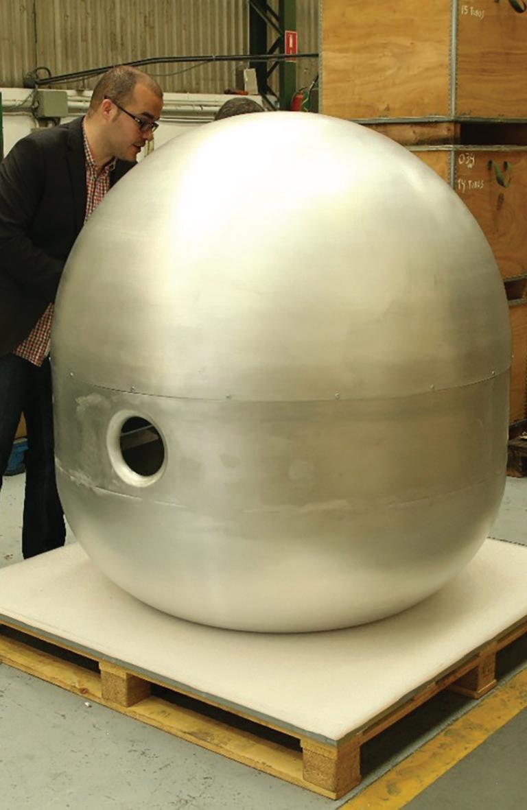
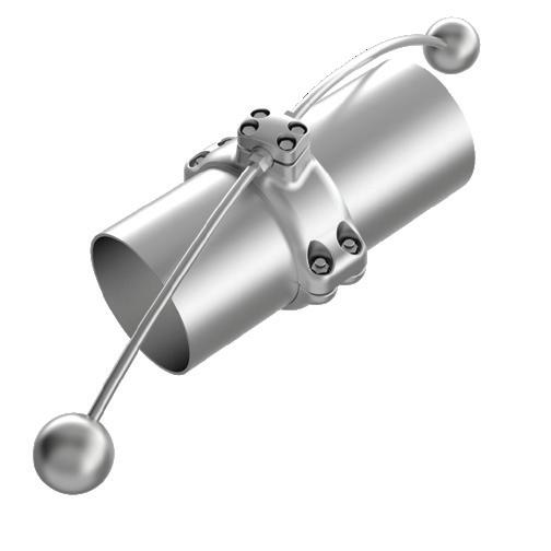
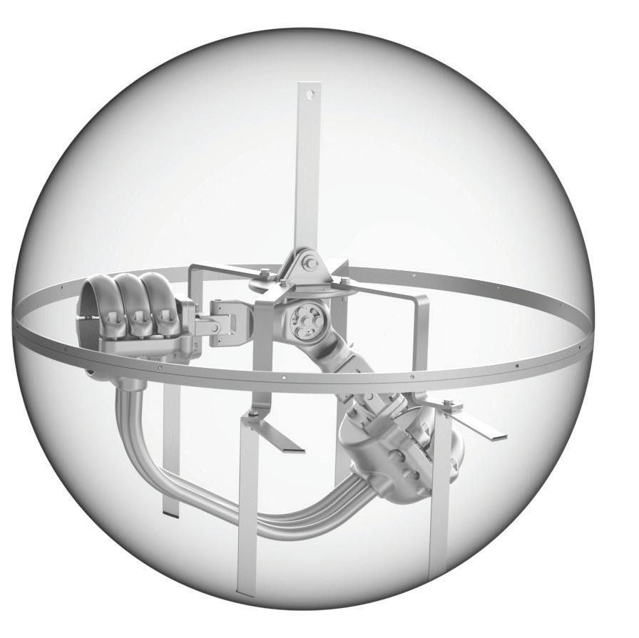
Sicame designed and manufactured all corona spheres protection as well adjustable connectors for 560 kV DC and 500 kV AC.
Celilo station converter
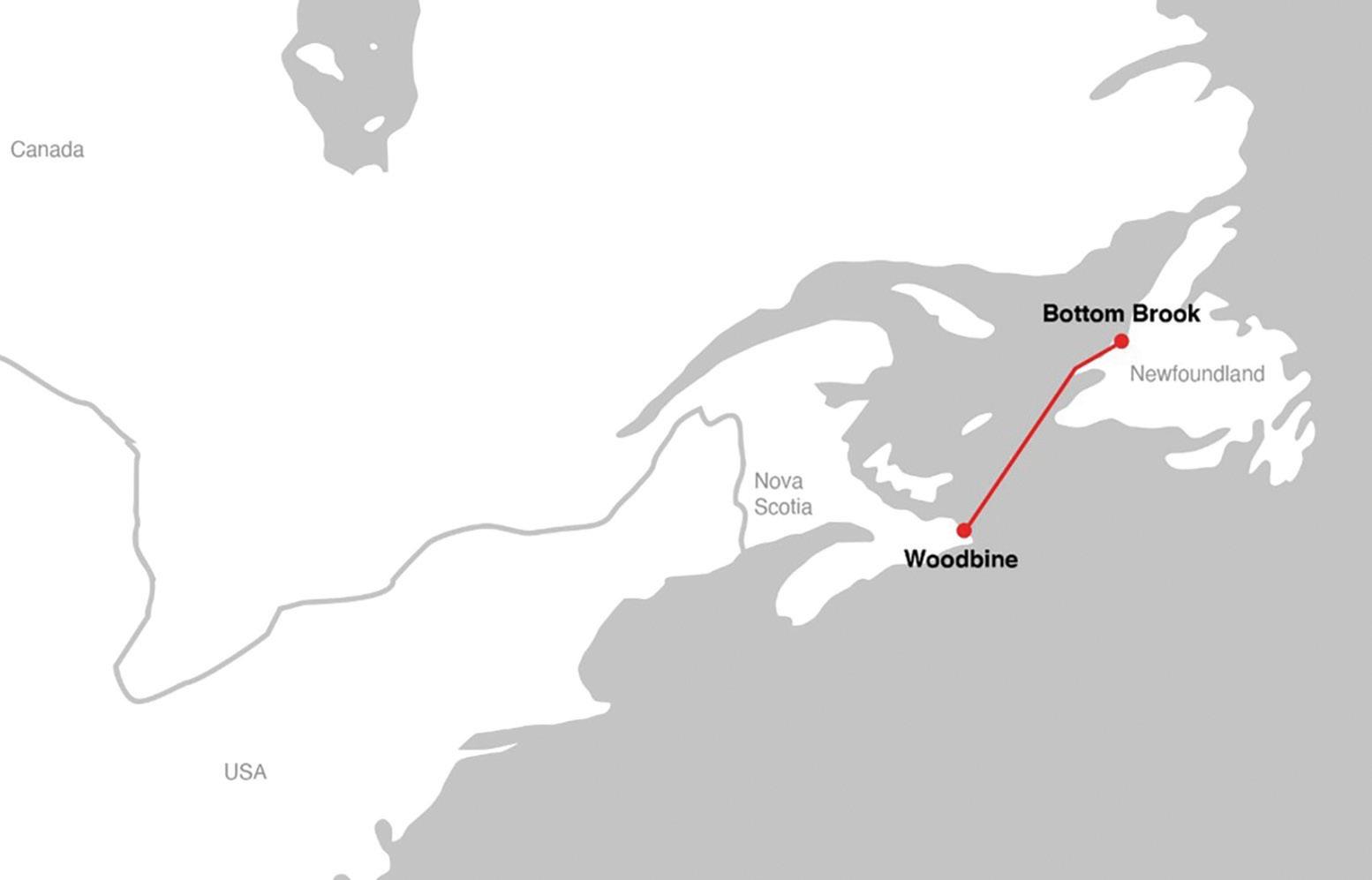
Maritime link project is the first electricity link between the island of Newfoundland and North America.
The maritime link project is a 500 MW high-voltage direct current (HVDC) connection that enables clean, renewable electricity generated in Newfoundland and Labrador to be transmitted to the North American grid in Nova Scotia. Integration of additional renewables is contributing to Canada’s emission-reduction efforts.
In addition to the two converter stations for the ±200 kV HVDC link, the project scope also included two 230 kV AC substations in Newfoundland, one 345 kV AC substation in Nova Scotia, and two cable transition stations.
Power transmitted:
500 MW
Direct voltage: ±200 kV
Maritime link HVDC station converters
These HVDC converter stations are part of the Manitoba Hydro Bipole III transmission project. The entire transmission line is acting as an “electricity highway,” bolstering the reliability of Manitoba’s electricity supply by reducing dependence on existing HVDC transmission lines and converter stations while also ensuring low-loss transport of renewable hydropower from northern generating stations to meet growing energy requirements.
HVDC converter stations are specialized substations that support the conversion of electric power from high voltage alternating current (AC) to high-voltage direct current (HVDC), or vice versa, a critical component to interconnecting separate power systems. The HVDC project consists of two stations: Keewatinohk and Riel. The Keewatinohk Station is located in the far north of Manitoba, about 45 km north of Gillam, MB. The Riel station is located outside of Winnipeg.
Voltage: 1000 V DC (+/-500 V DC)
Current: 2000 A
Bipole III riel station converter
Chibougamau SVC
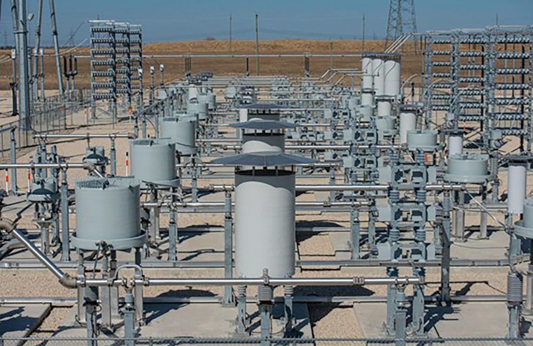
Sicame provided ultra high voltage connectors for SVC (Static Var Compesator) substation. SVC to stabilize a large 735 kV transmission system in Canada.
In Canada, Hydro-Québec is operating several Static Var Compensators (SVC) in its 735 kV transmission system. The 735 kV grid transmits a total of 15000 MVA of environmentally friendly hydro power over six lines from the generating stations along La Grande Rivière at James Bay down to the Montréal area some 1000 km to the south.
Purpose of SVC is:
• Regulate and control the 735 kV voltage under normal steady-state as well as contingency conditions;
• Provide dynamic, fast response reactive power following system contingencies such as network short circuits and line and generator disconnections;
• Enhance the first swing stability by maintaining system voltages during large disturbances
Un = 150 kV
In = 2.665 A
Icc = 29 kA/s
Un = 150 kV
In = 4.533 A
Icc = 40.3 kA/s
80 kA / 2 pipes
It is the first large-scale multi-terminal HVDC transmission in the world.
The project consists of building a transmission line extending approximately 100 km between Appalaches substation in Saint Adrien d’Irlande (near Thetford Mines in the Chaudière Appalaches region) and a connection point on the Québec–Maine border. The project’s overall aim is to increase the exchange capacity between Québec and New England.
The new 320 kV direct-current line will connect to the future New England Clean Energy Connect (NECEC) line, slated for construction in Maine.
In tandem with this project, a new AC-to-DC converter will be installed at Appalaches substation to supply the planned transmission line.
Sicame has provided high voltage connectors to be installed on the station converters. All connectors are designed and tested by our R&D experts to ensure the high level of performance required to work at this voltage level.
Necec HVDC station converter
Other reference projects worldwide
Meftah Substation
Mamba and Rilima substations
Lagoa Substation
Karnafuli substation
substation
Bipole III Riel and Keewatinhok substations
Cumbre and Changos substations
wind farm substation
Busbar vibration dampers installed in several substations in
and Akosombo substations
substation
substation
data center substation
Poggio a Caiano substation
Daugavpils and Grobina substations
Jhimipr wind farm and Quaid-e-Azam solar farm substations
Makow substation
Tavira substation
Ras Abu Fontas substation
kV Abqaig substation
CMS (Caithness-Moray HVDC link) Blackhillock and spittal station converters
Kaolack substation
and Kasserine Sud Substations
substation
substation
Al Taweelah and Al Ain substations
Krakovskaya ssuubbssttaattioionn
Nemo HVDC link - Richborough, Bolney and Ninfield substations
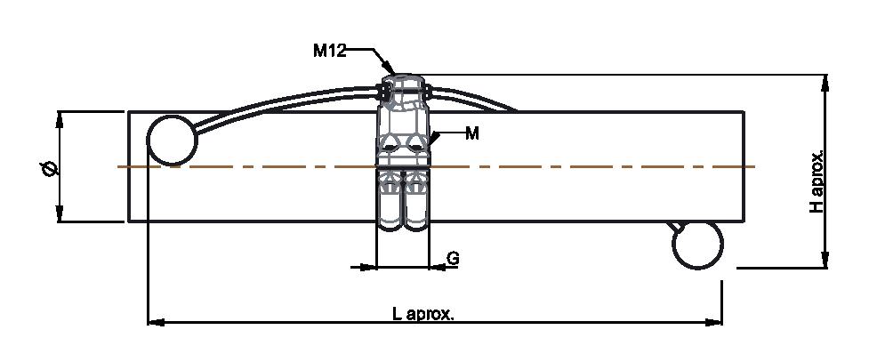
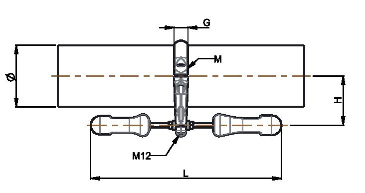
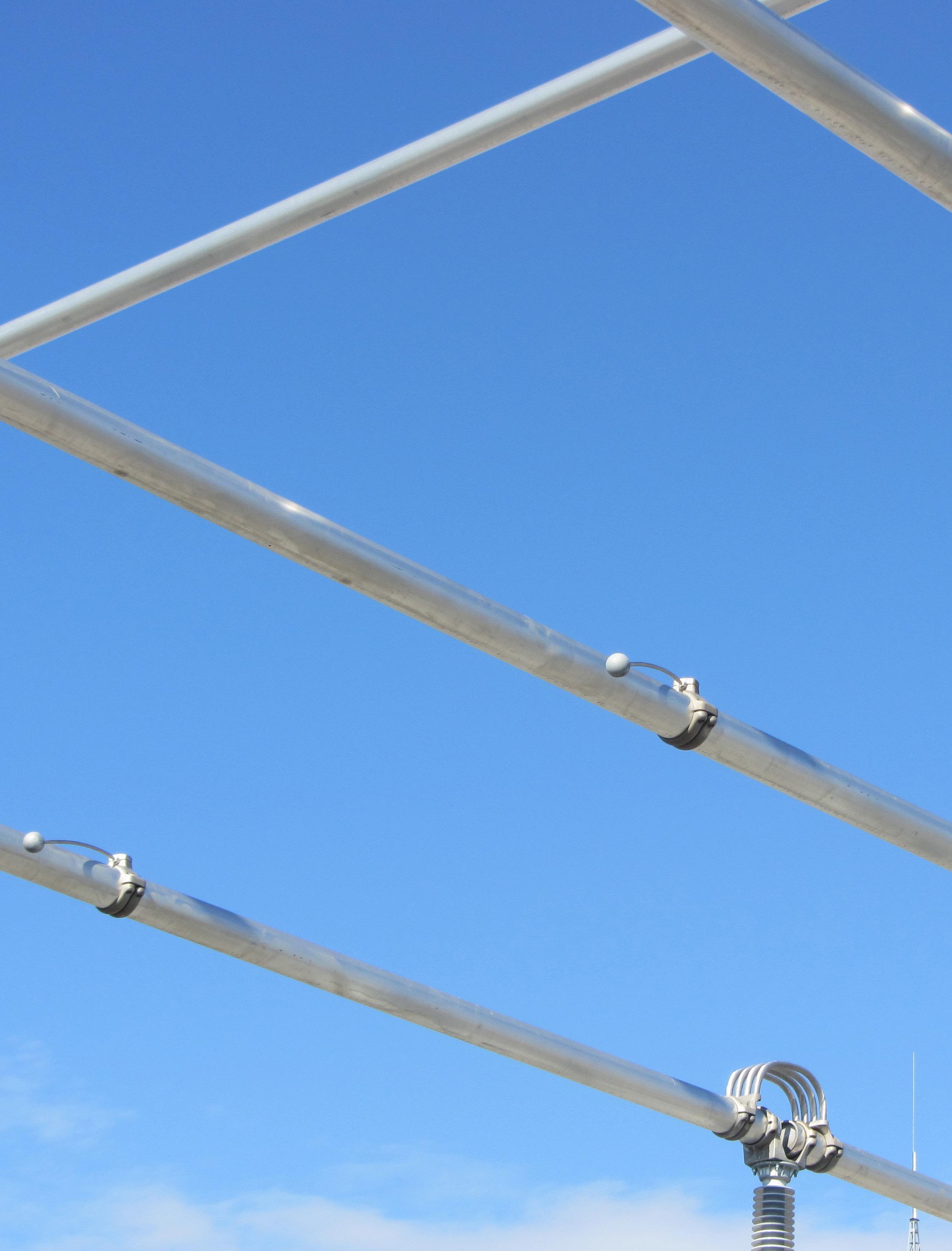
High voltage (HV) and ultra high voltage (UHV) substations are, depending on their geographical location, exposed to climatic conditions: special wind.
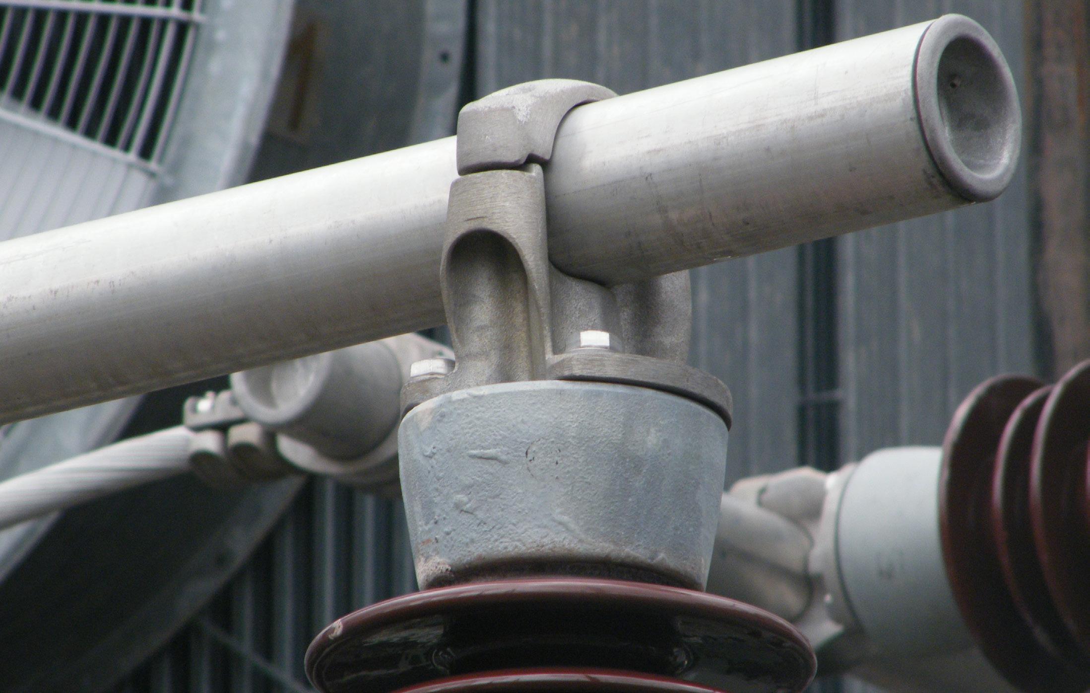
The wind causes sinusoidal turbulence to the substation busbars that in return causes variations in the carrying capacity with the fluid (air) moving in the same way as on an airplane’s wing.
In certain frequency conditions, busbars that are exposed to the wind can reach its natural resonance frequency (low frequency) that creates severe vibrations that can damage the installation.
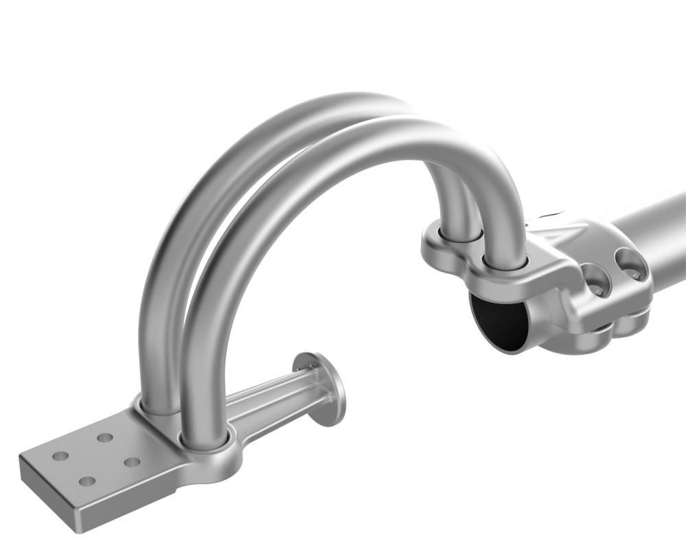
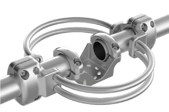
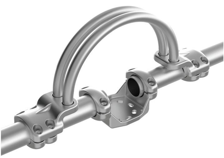
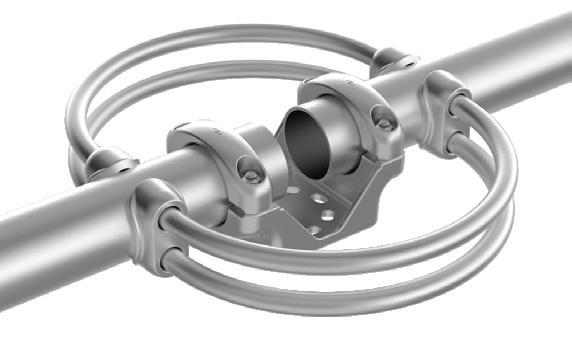
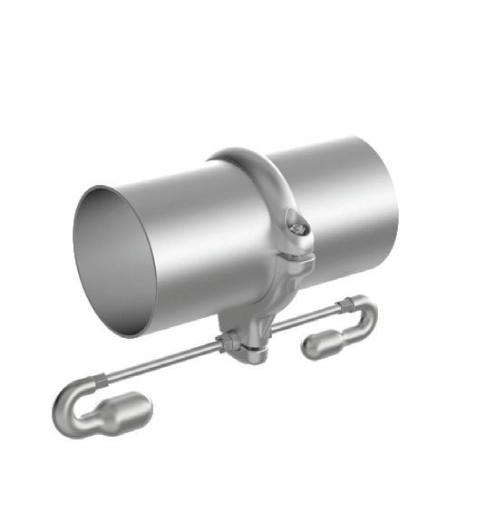
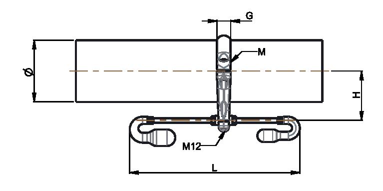
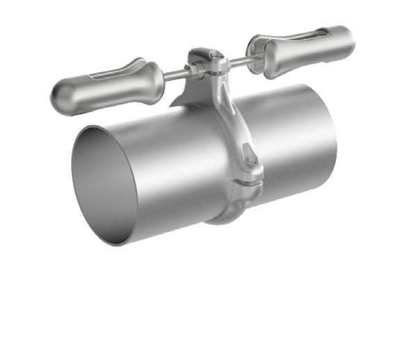
To solve this problem, a means of shock-absorption must be fitted to the tube that opposes and dissipates the vibration, taking into account the tube’s natural resonance frequency.
The most common solution to date is to place a cable inside the tube. But this cheap method is not satisfactory as the cable subjected to the vibrations may come out of the tube if the end caps are not properly tightened or welded they could be loose, creating a short circuit when they touch the ground.
Furthermore, if the cable within the conductor starts to vibrate, it may produce a noise that would be registered as a false-positive for a malfunction.
Being aware that the various current solutions are neither technically nor economically satisfactory, SBI Connectors in consultation with SALVI requested the participation of Milan (Italy) and Stellenbosh (South Africa) Polytechnic Universities in researching a new generation of dampers: the busbar damper.
This new generation is suitable for the majority of situations and is highly efficient. Following positive results from the experimental tests, the new damper offers the following advantages:
• Protects and lengthens the lifetime station equipment
• No maintenance is required because the counterpoise’s initial fixed setting
• Provides almost total dissipation of vibrations caused by wind
• Can be adapted to all existing stations
• Simple, quick configuration
• Cost effective
Damper A, B & C
Fig. 1
Fig. 2
Fig. 3
Table dimensions:
Table selection:
SDAM60BNS
SDAM60DNS 2
SDAM60ENS 2
SDAM60FNS 3
SDAM73BNS
SDAM73DNS 2
SDAM73ENS 2
SDAM89BNS
SDAM101DNS 2 SDAM101ENS 2
SDAM101FNS 3
SDAM114ANS
SDAM114BNS 1
SDAM114DNS 2
SDAM114ENS 2
SDAM114FNS 3
SDAM143ANS
SDAM143BNS 1
SDAM143CNS 1
SDAM143DNS 2
SDAM143ENS 2
SDAM143FNS 3
SDAM168ANS
SDAM168BNS 1
SDAM168CNS 1
SDAM168DNS 2
SDAM168ENS 2
SDAM168FNS 3
SDAM219ANS
SDAM219BNS 1
SDAM219CNS 1
SDAM219DNS 2
SDAM219ENS 2
SDAM219FNS 3
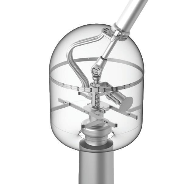
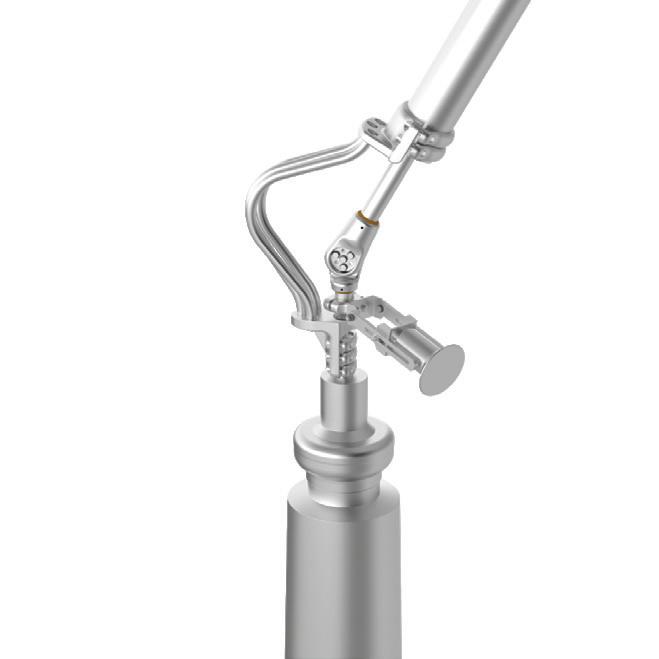
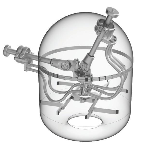
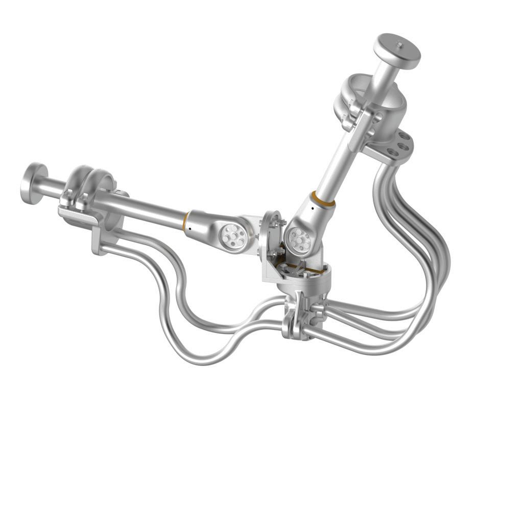
Busbar adjustable connector
current solution:
Disadvantages of the current solution
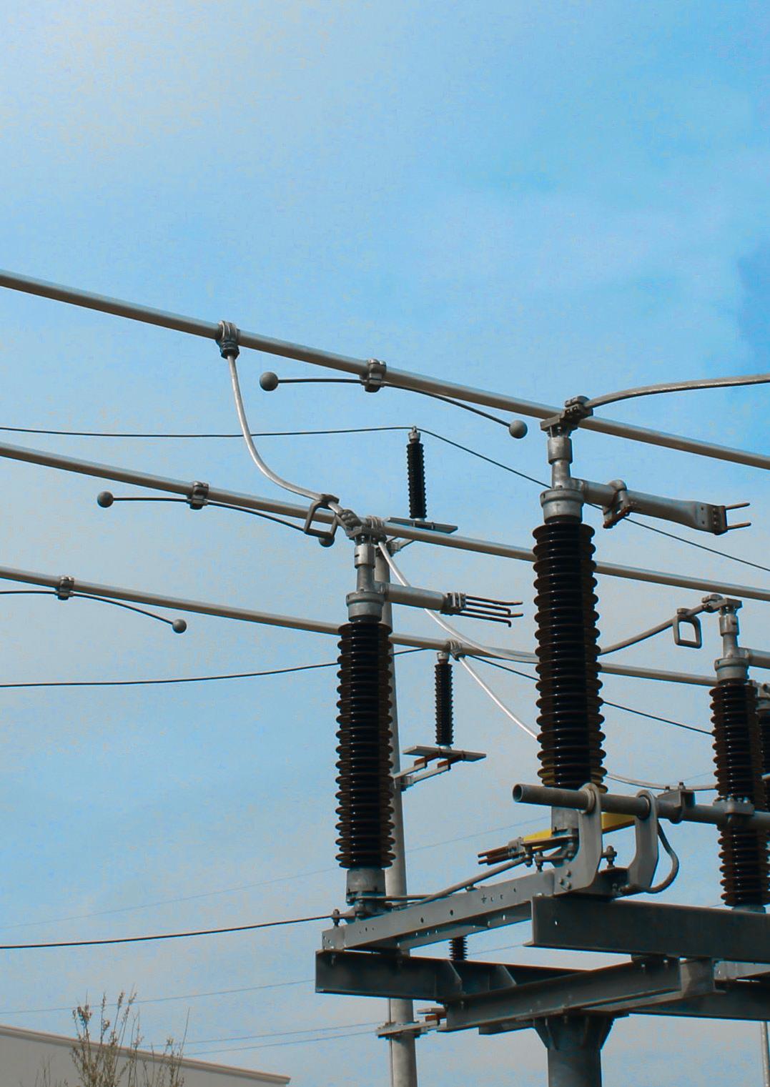
Angled busbar connections in most of the substations are obtained either by bending the tube or by welding an Aluminum sphere to join the tubes.
Welding operation must be made on site, difficult to perform due to the precision required, the weather conditions and construction site constraints.
Bending busbar operation must be done at the manufacturing plant using a special Aluminum alloy and heat treatment. This special manufacturing process increase the product cost. Special transport for bending busbars is also an additional expense.
New Sicame solution:
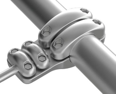
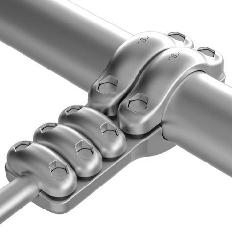
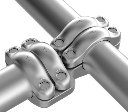
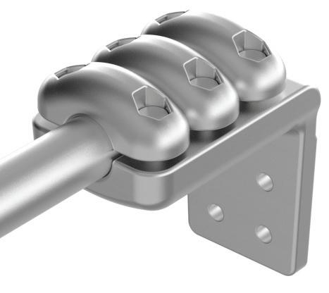
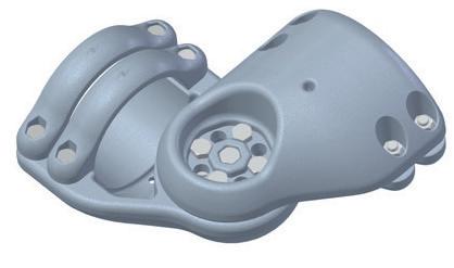
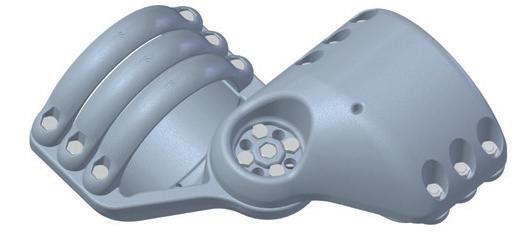
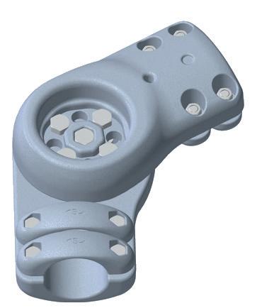
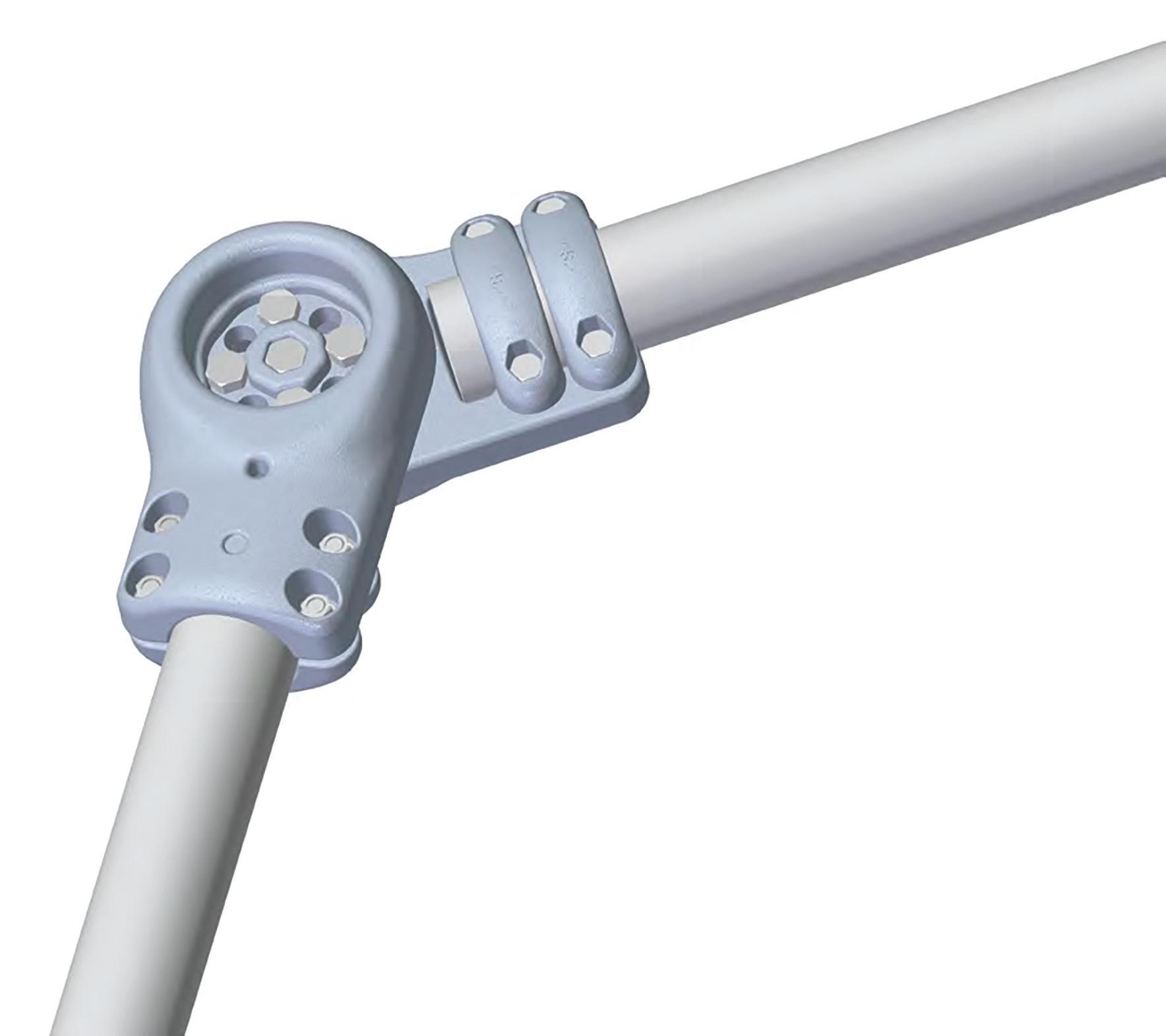
Elbow connector for busbar from 60˚ to 180˚.
• Adjustable on site
• Easy and fast installation
• Cost effective Design type for busbars from Ø 80 to 180 mm and Ø 200 to 400 mm
Most usual angle configurations:
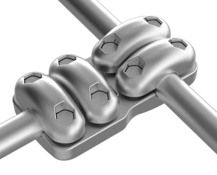
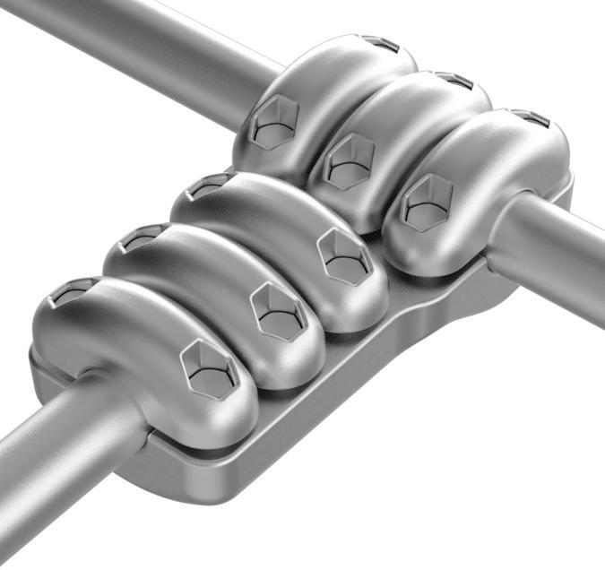
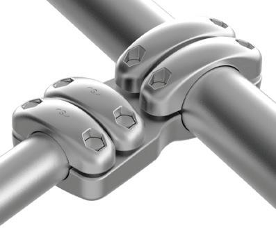
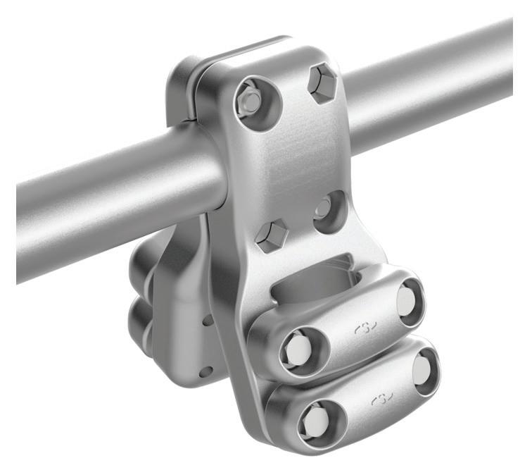
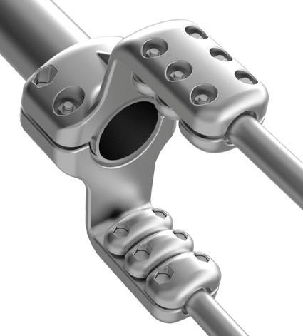
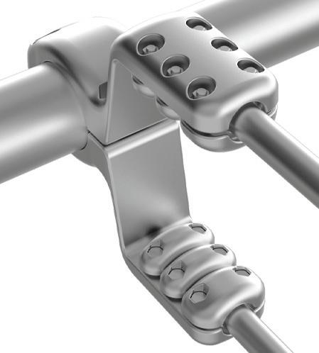
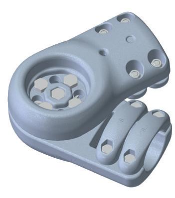
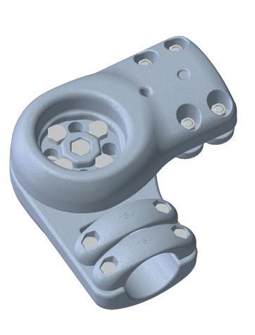
Adjustable connector that allows angular connections between Aluminum busbars from 60˚ to 180˚.
Adjustable connector solution avoids bending or welding busbars in the substation and makes installation work faster, easier and more cost effective.
Adjustable connector that allows angular connections between Aluminum busbars from 60˚ to 180˚.
Adjustable connector solution avoids bending or welding busbars in the substation and makes installation work faster, easier and more cost effective.
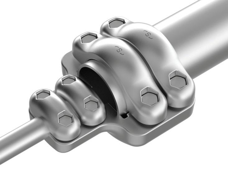
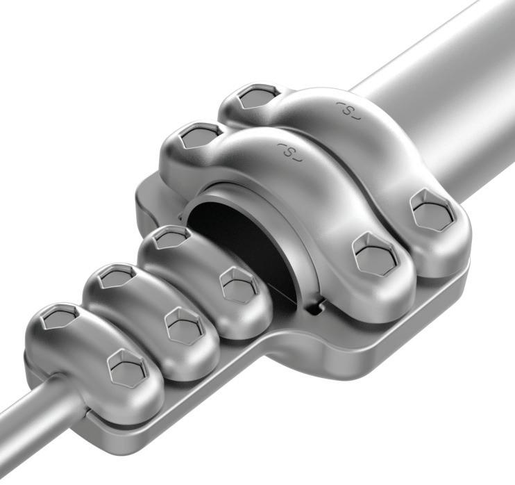
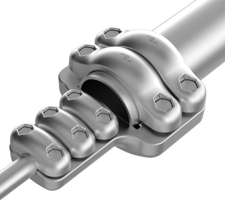
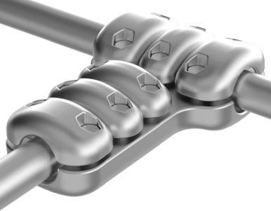
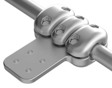
Special adjustable system with 5 bolts that assure a right contact surface performance and allow different angle configurations from 60˚ to 180˚ depends on the tube diameter.
Angle adjustment is possible by keeping the central bolt fixed without connection disassembly.
Screw, washer and hexagonal nut A2 stainless steel. Available under requirement in A4 stainless steel.
Body in sand casting silicon aluminium alloy primary fusion.
Caps in gravity casting silicon aluminium alloy primary fusion.
Possibility to connect different busbar diameters using the same adjustable system.
Corona simulation Simulation parameters
Solution for HVDC converters
HVDC (High Voltage Direct Current) Solutions
HVDC technology involves the transmission of electricity using direct current (DC) instead of alternating current (AC). In an HVDC system, electrical power is converted from AC to DC at a converter station, transmitted over long distances through DC transmission lines, and then converted back to AC at another converter station for distribution.
The primary advantage of HVDC over traditional AC systems is its efficiency in long-distance transmission. AC power loses energy due to resistance and inductance in the transmission lines, especially over long distances. In contrast, HVDC transmission reduces these losses significantly, making it more efficient for distances exceeding 600 kilometers (approximately 373 miles).
HVDC systems also offer improved stability and control. DC transmission allows for precise control of power flow, enabling grid operators to manage power distribution more effectively. This is particularly beneficial for integrating renewable energy sources, which can be intermittent and variable. Additionally, HVDC systems can connect asynchronous power grids, allowing for the interconnection of different regions with varying electrical standards.
Recent advancements in HVDC technology have focused on enhancing the performance and reliability of converter stations, which are critical components of HVDC systems. Innovations in power electronics, such as voltage-sourced converters (VSCs), have played a significant role in this regard.
These advancements in HVDC converter technology have had a significant impact on grid performance. They have enabled the construction of more efficient and reliable HVDC substations, capable of handling higher power capacities and supporting the integration of renewable energy sources. The improved efficiency and control provided by these technologies are essential for modernizing the power grid and meeting the growing demand for clean and reliable energy.
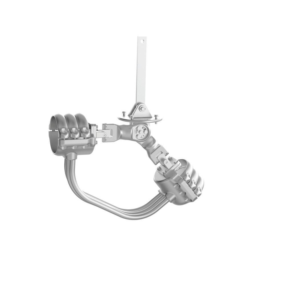
Sicame has extensive experience in the design and manufacture of connectors for HVDC station converters, and its products have been installed in several HVDC converter worldwide. Find here some examples of customized designs for HVDC converters applications.
Wildlife mitigation
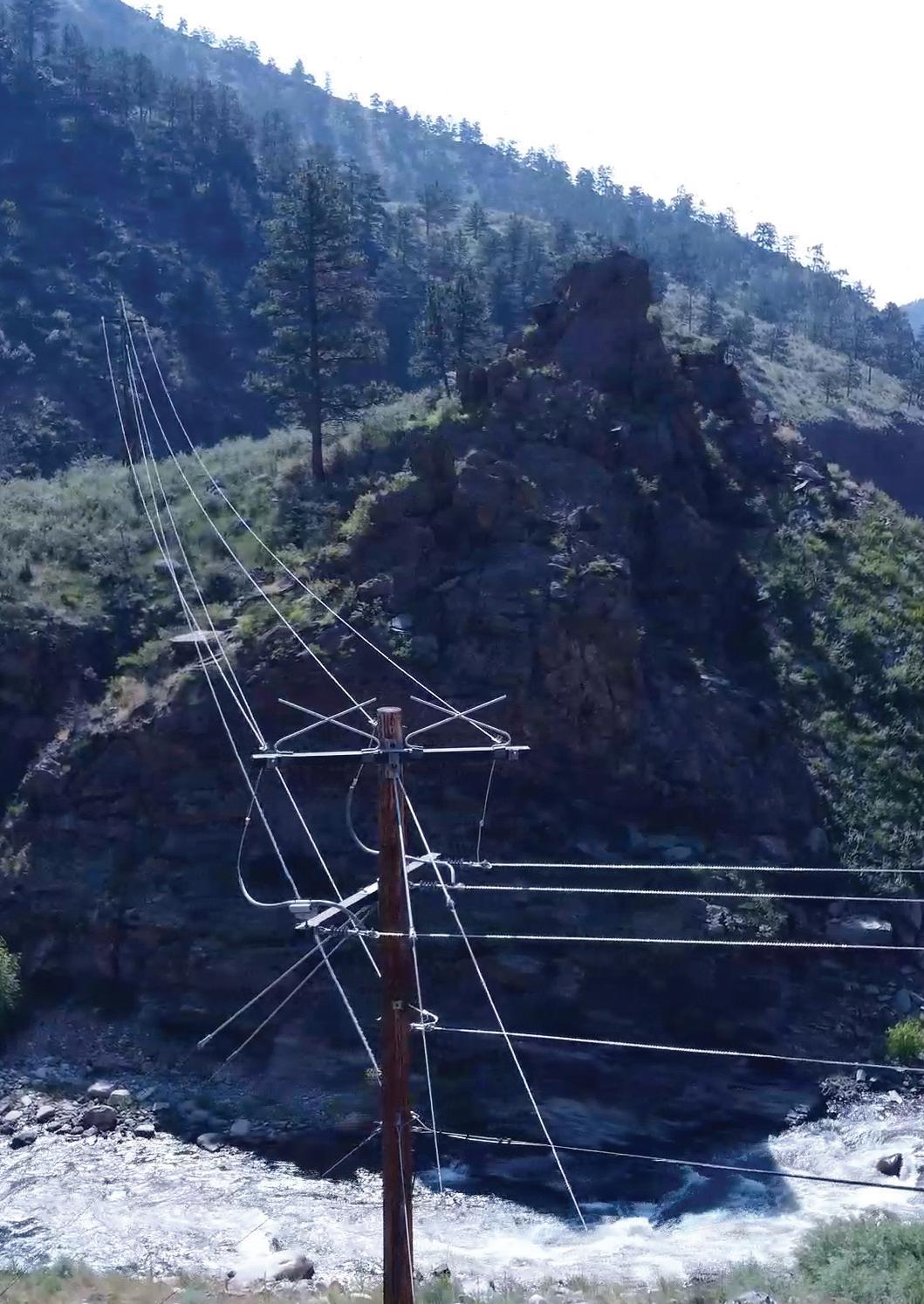
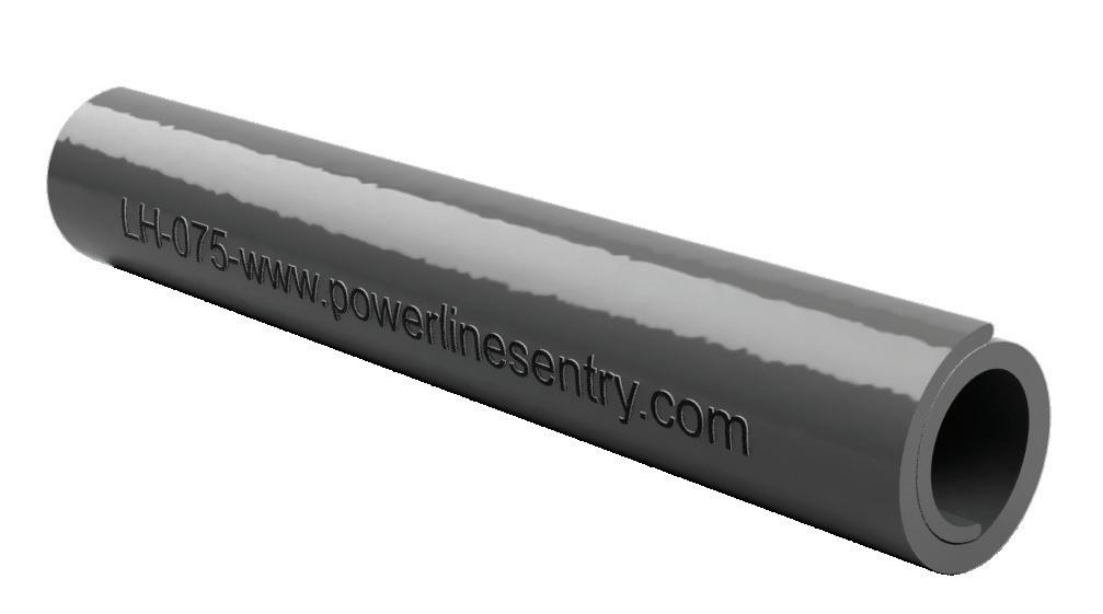
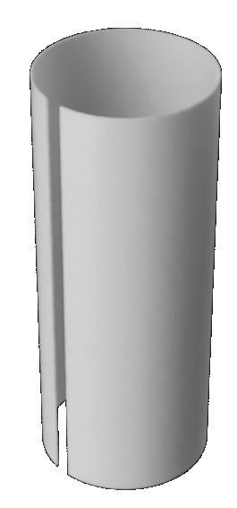
Line hose prevents electrocutions by insulating dangerous energized areas. It can be used on any bare or non-insulated area or wire to add insulating protection.
Only tear resistant line hose in the industry
• Best in class silicone Rip-stopTM line hose does not tear/ deteriorate/get hard/brittle
• Protects lines from contact-caused outages and adverse environmental conditions including vegetation, wildlife, weather, etc
• Available in gray and hi-viz orange or yellow
• 50% overlap provides superior coverage
• 35 kV insulation rating
• V-0 flame retardant material
• Easy hot stick or glove install
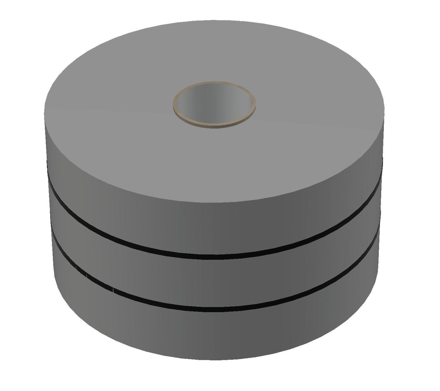
Fusing tape
Fusing tape provides an irreversible bond that is resistant to moisture, oxygen, ozone, UV, and corona over a wide temperature range
• Self fuses to seal
• Provides irreversible bond, but bonds only to itself
• Will not tear once sealed
• Protects over a wide temperature range
• Insulation barrier is resistant to moisture, oxygen, ozone, UV, and corona
• >15 kV phase-to-ground insulation rating per layer when installed with 2/3 overlap and 10% stretch
• >69 kV insulation available with additional layers
• Non conductive - provides <30 kV insulation per layer
Squirrel and woodpecker deterring pole wrap
V-O
Tests
ASTM D-149 Dielectric strength
ASTM D1822 Tensile impact
ASTM D746 Low temperature brittleness
ASTM D1693 Environmental stress crack resistance
Results
kV @ .040"
FT-LB/IN
°C
hrs
Universal cutout and loadbreak cutout covers
Cutout covers insulate exposed portions of cutout equipment to prevent electrocution events and power outages.
Adjusts to fit
• Only adjustable cover in the industry
• > Standard cover clips provide 2” (5 cm) height adjustment for universal secure fit on most polymer and porcelain 100 and 200 amp cutouts
• > Loadbreak cover features Raptor ClawTM roto lock for adjustable internal diameter, providing a universal secure fit on ABB, Hubbell-Chance, Aluma-Form and Maclean style loadbreak cutouts (shed widths up to 5”)
• Neck adjusts to the size of the cutout for a tight and secure universal fit
• Fully covers all energized portions
• Allows insulator sheds to naturally clean
• Open design allows for easy access during inspections
• Standard cover allows for load break tool access
• V-0 flame retardant material
• Hot stick friendly, snaps into position, no locking pins
Hotstick Attachment Point
CT-D04
most polymer and porcelain 100 and 200 amp cutouts
ABB, Hubbell-Chance, Aluma-Form and Maclean style loadbreak cutouts (shed widths up to 5”)
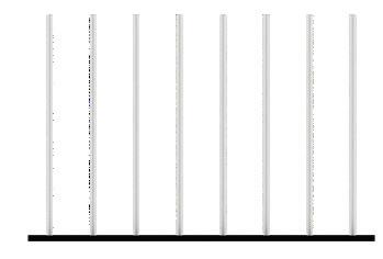
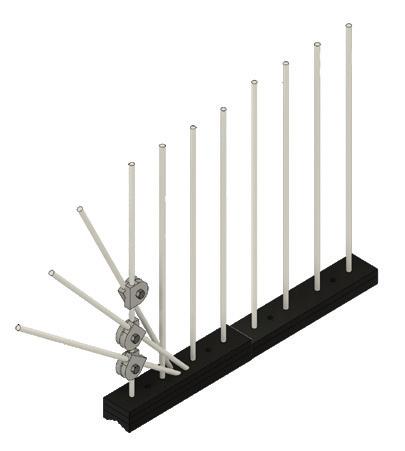
Perching excluders on transmission structures isolate dangerous energized areas and deter birds of prey from using structures as hunting perches.
Adjusts to fit
• Blunt-tipped solid fiberglass spikes deter perching, as proven by live flight cage raptor tests conducted in collaboration with the Rocky Mountain Raptor program
• Engineered to maintain structural integrity under extreme environmental conditions for decades
• Durability and effectiveness have been highlighted in the pilot programs by the Washington State fish and wildlife and the bureau of land management
• Optional side extension covers vertical insulators or ends of cross arm
• Self-extending rods: the lower end of each rod has a point intended both for driving in and connecting; the upper end is pierced, receiving, without any sleeve, the point of the previous rod
Features:
• Steel with copper electroplating: minimum thickness 350 μ m
• Resistance: ≥ 70 daN/mm 2
Cosses C2C-95Z, TO-2-19 and TO-3-16/19
A3MC-15Z Cosses C2C-95Z, TO-2-19 and TO-3-16/19
Accessories:
• Driving pins: CH-MZ, CH-LMZ and CH-MP
• Connection terminals: C2C-95Z, TO-2-19 and TO-3-16/19
C2C-95Z
A3MC-..-
A3MC-..-
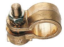
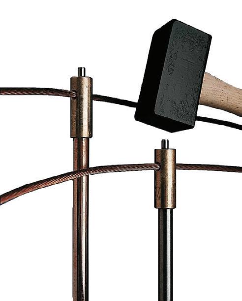
Connector heads for earthing rods
Connector heads for earthing rod.
Network type: LV
Application:
• Head/rod connection obtained by conical press-fitting with force
• Head/cable connection made by striking a stainless steel peg located in the upper part of the head. This strike guarantees the connection head/posts and head/cable
• For earthing rods: Ø 17,3 mm copper-steel and Ø 16 mm stainless-steel
• Right-angled running through copper cable 25-29 mm 2
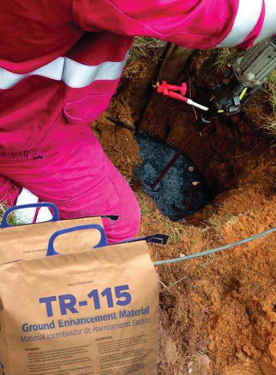
Improvement of earthing systems
Improvement of earthing systems.
Network type: LV | Standards: IEC 62561-7
Application:
• Material of very high conductivity which considerably improves the efficiency of earth circuits
• Spread around the earth conductors at the bottom of the trench, it allows to locally reduce earth resistance and impedance
• Can be used dry or mixed with water
Physical and chemical features:
• Solubility in water: not very important
• Specific gravity (H 2 O=1): 0.9
• Melting temperature: 3500 ° C
• Appearance: grey powder
Composition:
• Aluminum silicate hydroxide
• Carbon
• Hydraulic binders
• Quartz crystals
• Dust fixing oil
• Sulphur
Grounding and short circuiting equipment
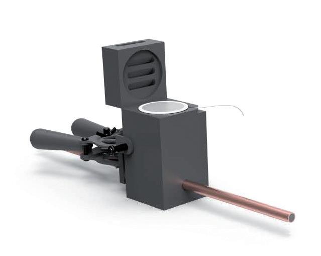
Exothermic connection
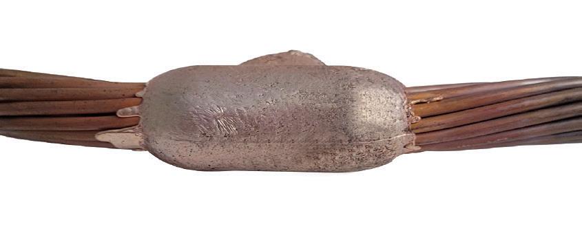
The ultimate solution for safe and reliable exothermic connections
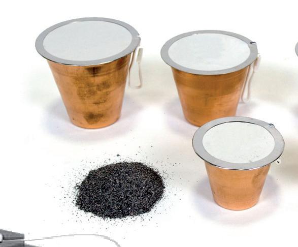
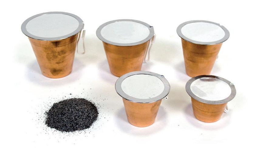
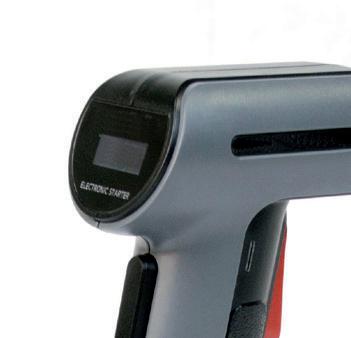
Cat’advanced weld consists of the following components:
Graphite mold Ref. CEW-XXXXXXX
Handle clamp Ref. CEW-HC
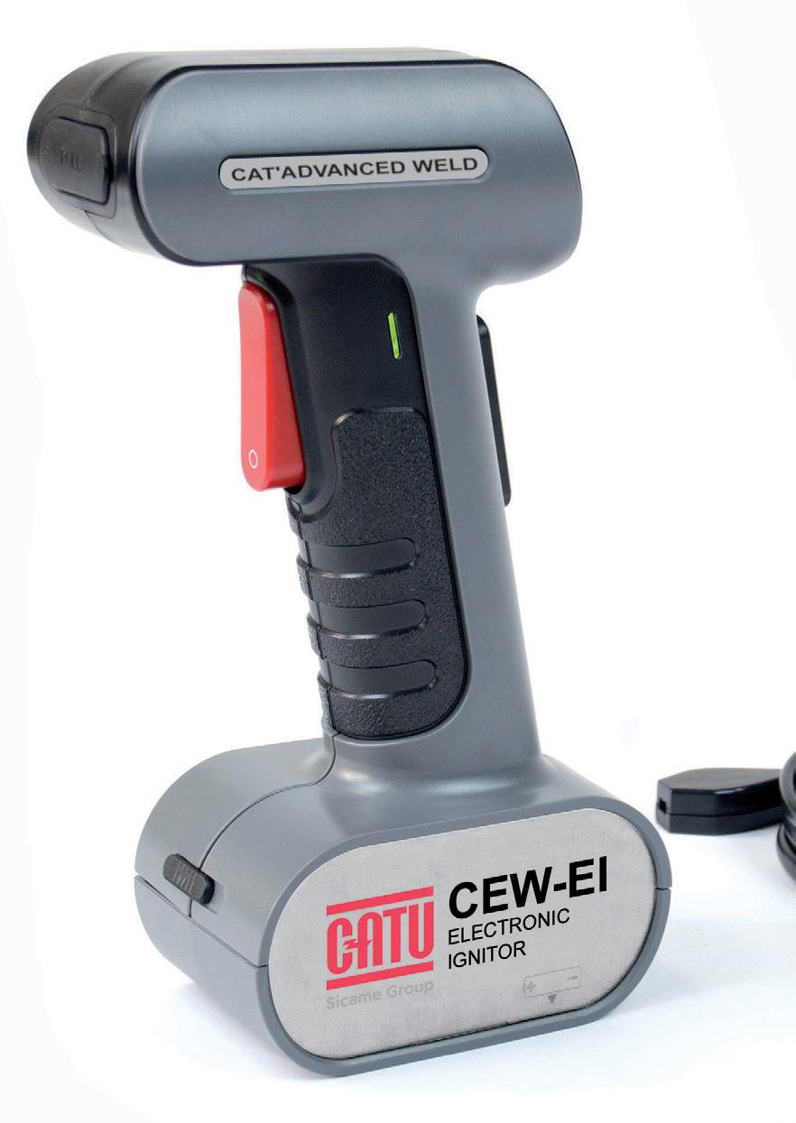
LED display screen: - battery level status - number of welds performed
Cup of welding powder Ref. CEW-WPWW
Gloveasy
Superior performance:
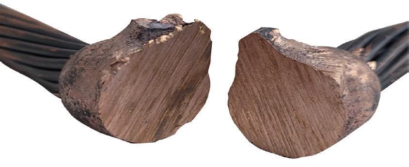
• High-quality electrical connection: Achieves a molecular bond that ensures long-lasting durability
• Corrosion resistance: Designed to withstand harsh environments, ensuring reliability over time
• High conductivity: Ensures optimal electrical performance
• Mechanical strength: Exceptional resistance to mechanical stresses
User-friendly:
• Fast installation: No need to handle welding metal - simply “plug and play”
• Easy to use: Simplified installation to reduce the risk of error
• Quick setup: Achieve a permanent connection in 5 steps
• Easy to store and transport: No starting powder included in cup
Electronic ignitor
Handle clamps
Welding powder
mold
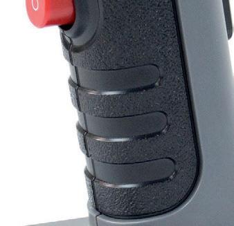
Safety light and warning sound Ignition starts when pressing 2 keys simultaneously
Minimum of 5000 welds
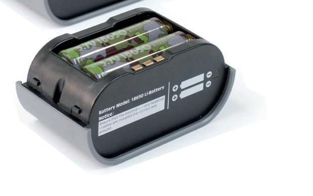
Delivered with 1.8 m lead and Type C charger
Used to close the mold
Unique handle clamp for all configurations
Gloveasy: user-friendly to operate with gloves Ergonomic
Heat resistance
Self contained welding material with copper oxide and aluminium Safer transportation and storage
Available in 65 g, 90 g, 115 g, 150 g, 200 g ie : CEW-WP150 (welding powder 150 g)
Delivered with metal plate indicating the quantity of powder required (from 65 to 200 g)
Part number to be defined according to customer needs ie : CEW-050T050 (T connection for 2 cables of 50 mm2)
Extensive configurations to meet your needs
CAT’ADVANCED WELD offers a range of configurations to suit multiple applications: