9 minute read
Rolling your own…


In my last article we had a look at some of the reasons behind how and why we determine an estimated weight and balance, and determined the estimates on our Concept 3 aircraft. I have since had a play around with various combinations of pilot, fuel and baggage weights and determined that the geometry is working out OK for this design.
How so? Well, the worst forward case gave me a CofG position at 22% of the chord back from the leading edge, while the worst aft case gave me 32% which is sensible for a traditionally configured aircraft.
Detailed specification
I outlined in the April Issue the differences between a basic and detailed specification and that we will be populating our detailed spec this month. Something that needs to be done before we can continue towards making estimates on stability and aerodynamic loads.
To do this, I am going to cheat slightly. I have my scale drawing from which all the parameters can be taken to populate the LAAs own ‘Aircraft Data’ spreadsheet.
You don’t have to use this spreadsheet, but spreadsheets make otherwise monotonous calculations much quicker and considerably less soul destroying, should you find an error.
To find this spreadsheet, go to LAA Website>Main menu>Engineering>Designing Aircraft> Preliminary Design>Aircraft Data Spreadsheet.
Should you wish to know what these calculations are and how they work, you can either reverse engineer the spreadsheet or buy a good aircraft design book, such as *Hiscock’s, which will show you how to calculate all these manually… I have done it this way in the past and it does get very repetitive, especially if you need to go back and alter something in the design causing the need to repeat everything, each time a change in geometry is made.
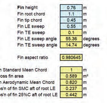
You can see the detailed specification in Figure 1. Note: more information will be added in later stages, such as airfoil data.
Stability analysis
Can we determine the exact stability of our design? Yes, but it involves quite a lot of complex calculations. You can do these if you wish, but quite a lot of very successful homebuilt designs have been developed without going to these lengths. Forthunately, we can get a good idea of the static stability using basic formulae and the information contained in the detailed specification. The LAA’s Aircraft Data spreadsheet will determine these for us, but if you’re curious, then here’s some more detail.
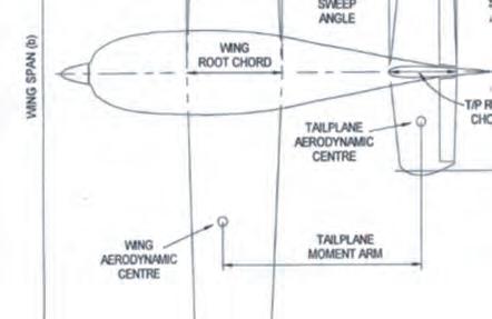
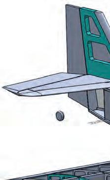
To determine the various coefficients, we will need some geometry data from our three-view. Figure 2 provides a simple illustration of what values we will need.
· Fin Volume Coefficient
Fin volume coefficient = (fin area x fin moment arm) / (wing area x wing span)


The best way I can describe this, is that it is an indication as to how much it wants to keep straight. The higher the value the more it wants to align itself with the oncoming airflow; the lower the value, the more it will hunt, like an arrow or wind vane with too small a tail. We are looking for a value between 0.02 & 0.05. LAA’s Head of Flight Test, Andy Draper, once told me that during the development of the Europa, the original tall fin gave a very ‘stiff’ directional stability, so it had to be reduced in height by several inches – in other words, its fin volume coefficient was too high. You want the aeroplane to be reasonably stable so that it doesn’t need too much footwork to keep straight in normal flight, or in turns. But
Lv = Length to vertical tail (to the aerodynamic centre of the fin)
Lh = Length to Horizontal tail (as above, but for the tailplane)


Sv = Area of vertical tail

Sh = Area of horizontal tail too much directional stability makes the aeroplane undesirably responsive to side gusts in flight, and very difficult to deal with in a crosswind landing, where the pilot has to purposely yaw the aeroplane just before touchdown to line up with the runway. Too much weathercock stability can even make it difficult to taxi across wind.
· Horizontal Tail Volume Coefficient
Tailplane volume coefficient = (tailplane area x tailplane moment arm) / (wing area x wing mean chord)


The tailplane volume coefficient is the equivalent to the fin volume coefficient, being a measure of the tailplane authority for the behaviour about the pitch axis. The two coefficients work out with very different values, however.

The fin volume coefficient is inevitably much smaller than the tailplane volume coefficient not only because the fin area is less than the tailplane area, but also because the ‘characteristic length’ divisor for the fin volume coefficient is the wing span whereas for the tailplane volume coefficient it’s the wing mean chord We are looking for a value between 0.3 & 0.6
If the value is too small, the aircraft will be unstable in pitch and be very sensitive to changes in CG. If your design has powerful flaps, you will probably find that you need a horizontal tail volume coefficient towards the upper end of the range to cope with the change in trim that you get when the flaps are extended.
Spiral Stability
After determining the tailplane and fin sizes for your design, to give you the right level of stability in pitch and yaw, the next thing to consider is the spiral stability, that is, the tendency to recover to wings-level if it gets banked over by a control input or gust. A spirally stable aircraft will almost immediately lift the depressed wing and resume level flight, while an unstable one, left to its own devices, will gradually increase in bank angle and would wind up in a tightening spiral dive if the pilot didn’t take notice and intervene first. The spiral stability is chiefly determined by the combination of the wing dihedral angle and the size of the fin, and also, whether the wing is mounted on the fuselage in the high or low position. The greater the fin area (or strictly, the fin volume ie fin area x fin moment arm), the more dihedral angle is needed to achieve a particular level of spiral stability.
The dihedral angle produces lateral stability which is generally a good thing, but it does tend to erode the control authority in roll. Hence zero dihedral in combination with a large fin gives good results in something like an Extra 300 where aerobatic manoeuvrability is most important and spiral stability isn’t a problem because the pilot is very much ‘hands on’ throughout. At the other end of the scale, generous dihedral suits an aircraft intended for touring or gentle pottering. Avoid a lot of dihedral in combination with a small fin size, as this configuration is prone to so-called ‘Dutch Roll’, where the aircraft tends to oscillate in combined roll and yaw in a fidgety fashion. Choosing the ideal dihedral angle for your design could fill a book, but as a basic rule of thumb, if your design has essentially unswept wings and a typical layout then if you use between zero and two degrees dihedral on a high winger, and between three and five degrees with a low wing, and use the higher end of the ranges if you want a more stable platform, then you won’t be far out. For an all-out aerobatic low or mid-wing machine you might choose to have no dihedral at all. Remember though that an optical illusion always makes a high wing with no dihedral look ‘droopy’, it needs a degree or so to look ‘right’.
Controls free
For the volume coefficients, the LAA spreadsheet assumes the area of the rudder and elevator as part of the equations, this gives a ‘fixed stick and pedal’ value. If we wanted to get an idea of ‘hands off’ stability, remove the added control surface areas in the equations and just use the fixed elements. This gets tricky if it’s a flying stabilator or fin, as seen on the Europa or VP1, which generally use anti-servo tabs to make them behave part-way between a fully fixed and a fully free surface. The Tiger Moth is an example of a type, which because it has a large rudder and small fin, is directionally quite stable ‘feet on’ the pedals, but if you remove your feet from the pedals in a full power climb, the ball will move to one side as the aeroplane diverges in yaw of its own accord.
Choosing safe values for our coefficients puts us in the right ballpark and we can be pretty sure that given a sensible CG position our design should fly well enough right off of the bat, and if necessary the design can be finessed during flight testing based upon the opinions of experienced test pilots. If you are designing something that is a little unusual and not of a traditional configuration, then the above formulae won’t work without making some adjustments.
While I have more than enough faith in my design’s stability based on the values I have calculated, I may also build a 20% scale Radio Control (R/C) model to give further confidence. An R/C model aids in determining a CG range as well as control surface deflections – but do remember, because its control surfaces are connected rigidly to servos, rather than free to find their own position in the airflow, an R/C model enjoys enhanced ‘stick fixed’ stability compared to its full-size counterpart.
Rather than build an R/C model, you could do this equally well if you ran multiple CFD (computational fluid dynamics) simulations or perhaps used flight simulation software like X-Plane. Did you know that NASA and Lockheed frequently build sub-scale demonstrators as they are often cheaper than large wind tunnel models? All these methods to boost faith are possibly overkill in such a normal configuration of aircraft as we are contemplating in this series, and possibly just an excuse to build another R/C model…


Concept 3 Stability

From our detailed specification, we can use the formulae mentioned prior to plug in the variables and see what we get (Figure 3).
· Pitch Stability Plugging in the variables for Horizontal makes it not as effective at a straight fin such as those found on an RV or Eurofox. In other words, sweepback of the fin will promote spanwise (or fin-wise flow), which will reduce the lift curve slope of the fin, so we’ll need more area to compensate.
Tail volume gives us a value of 0.60 which is a sensible number. If this was too large or too small then I would need to make changes to the tailplane or the tail moment arm, which would mean adjusting my three-view, weight and balance and detailed specification. For now, though, the value of 0.60 should work fine.

Remember what I said earlier about these accepted ranges of coefficients relating usually to ‘stick fixed’? The coefficients I attained assume that the elevator and rudder are fixed in position. So hands-off, the values would actually be less, giving less stability. If my coefficients had turned out towards the bottom end of the accepted range, and / or my design had particularly large control surfaces in relation to the fixed fin and tailplane, then I would probably do another design iteration to get my design into a more stable configuration, rather than risk it being dangerously unstable.
Beware of the aft CofG trap, where your aeroplane turns out with an aft CofG, which tends to make it unstable. You could cure this with a bigger tailplane, but of course that would move the CofG even further back, which would then require a bigger tail still… If in doubt, remember it’s much easier to cure a CofG that’s too far forward than one that’s too far aft.
Looking ahead
I really want to show how an amateur designer might go about designing an aircraft. These articles account for just a few per cent of the total effort put into this design, and the word count for the articles means it’s a question of knowing what to include and what to leave out.
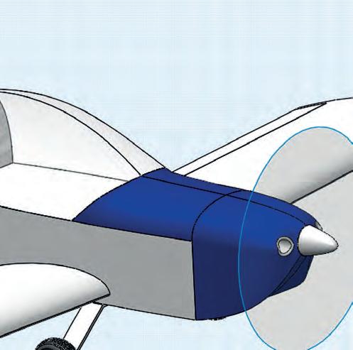
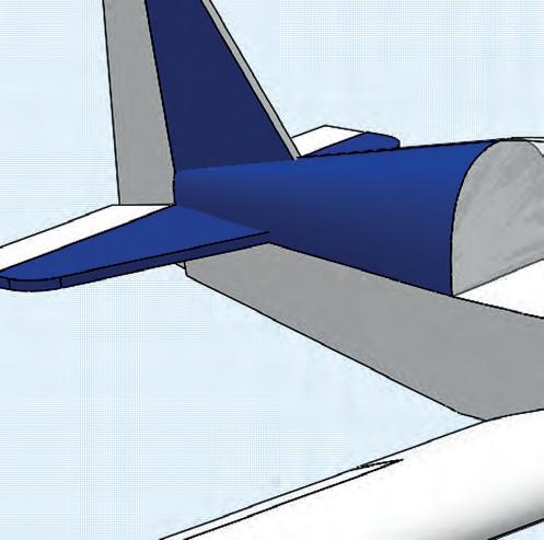
So you know where all this is headed, Figure 4 currently shows how far I have got. The design is actually very nearly finished, and all my calculations need to be taken from the notepad to a more professional looking report. I will be covering some of the loads and stressing in a future article, and anticipate the next one to cover airfoil selection and performance estimates. If there is a particular element of the detailed stressing work that you are interested in or want to see, email the editor, let him know and I’ll try to include it.
· Directional Stability
It is calculated that the fin volume coefficient is 0.06. This is actually quite high for a fin that, to me, looks slightly on the small side. However, I won’t change this because of the significant fin sweep, which
Finally, I’d like to thank Francis Donaldson for casting a wise eye over this article. ■
*Hiscocks: This refers to the excellent paperback book Design of Light Aircraft by Richard D Hiscocks


