9 minute read
Rolling your own…


At the end of part one, having come up with our design concept I mentioned we would move on to coming up with a detailed specification. First, I have to confess to having made a few changes… Why, you ask? Well, for a number of reasons, but it goes to show how quickly things can change when designing an aircraft, especially this early on!
The new concept
What are the changes I have made? Well, numerous, but the most notable is in the choice of powerplant. What has become Concept 3 is now designed around the use of an industrial V-twin engine of approximately 28-32hp, rather than the previous idea of a VW engine. I have chosen this powerplant as, while the VW is a very proven conversion (in most of its flavours), the industrial V-twin has had great success in the Luciole and SD1 Minisport as well as several other one-off aircraft that appear to be doing well. The industrial V-twins have enough flight time to show merit in their use as an aircraft engine. Not to mention that a brand-new Briggs & Stratton engine will only set you back £1,500 or so… double it, by the time it is configured for flight. The industrial V-twin also benefits from excellent fuel economy, if you design an aircraft to fly on 25hp, it should prove economical, right? We will investigate that at a later date when we do our performance estimates. this is where we can make some educated guesstimates on our empty weight and balance. Should any problem areas arise, we can go back to our concept and make some tweaks… If the CofG becomes very sensitive to pilot weight, maybe we can move the pilot forward, or shift the wing back. Can the tail be made larger? Can we increase our payload should our estimates come out heavy? Will we need a bigger wing area? Usually, the first step is making a scale drawing on graph paper from which accurate measurements and areas can be taken to form a basic and detailed specifications.
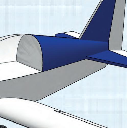
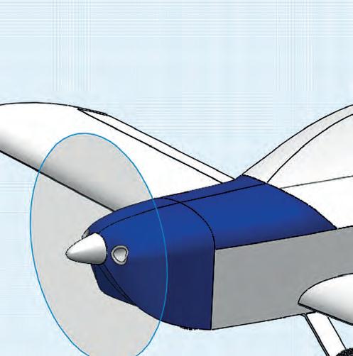
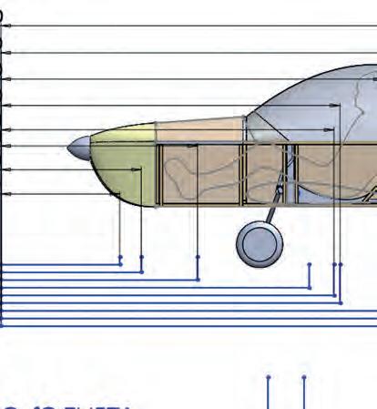
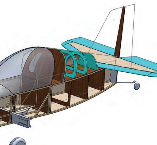
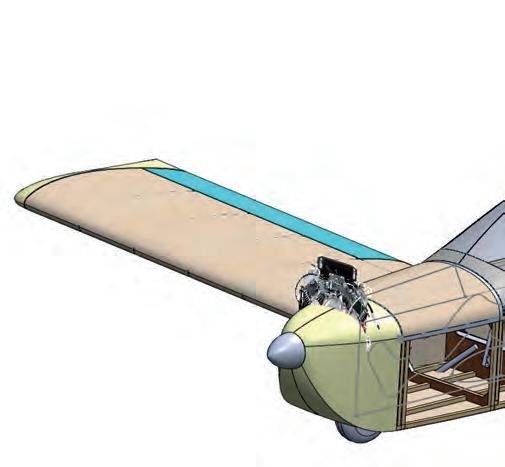
Above Some changes since last time, gives us Concept 3.
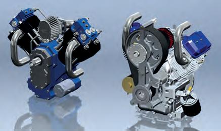
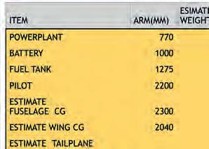
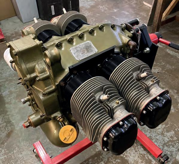
Right Briggs and Stratton V-Twin.
So, for the other changes? Well, the aircraft is smaller, lighter and generally looks prettier (in my mind). It won’t meet the 140kg payload target, but I am happy to accept that as it will be designed for a 130kg payload instead, meaning bigger fellas like myself can still fly it… It’s also not much of a hindrance as V-twins in this power range typically burn 5l/h… as opposed to the VWs 12-16 L/h.
You may be wondering if there are any drawbacks? Well, there are. First and foremost, we now need the aeroplane to perform on not much more than half the power we were previously contemplating, so we’ll need to be more focused on minimising weight and drag to make it viable. I’ve also decided that this design will have a bubble canopy. I initially planned on a canopy that used three single pieces of acrylic that are only being bent in one plane which should, in theory, make for a much cheaper and simpler canopy. The reason I decided against this simpler canopy was that I could not get the single-curvature canopy to fair in where it met the curved fuselage sides and turtledeck. It would work just fine, but it looked ugly, and I didn’t like it.
Basic specification: The specification that is given on nearly all aircraft manuals typically include wingspan, wing area, chord (or aspect ratio) length, height, MTOW, number of seats, powerplant and sometimes fuel quantity. If you look on Wikipedia for any aircraft design, it usually shows a very good basic specification for the type.
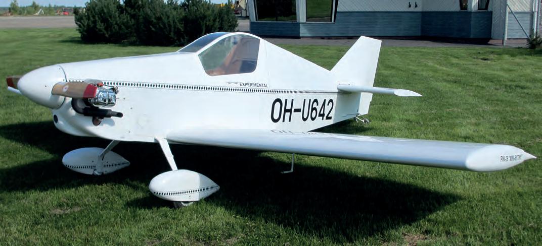
Also, once I put the model in CAD, I found that the pilot could not turn his / her head to look over the wing without grazing their nose on the Perspex. Making the sides of the canopy more nearly vertical to give the pilot’s head more room, only created a very boxy looking aircraft. Again, it looked ugly. The PIK-26, a lovely single-seater created by the Finnish aircraft designer Kai Mellen, has achieved good looks with an angular canopy by having a splice in all four fuselage longerons, meaning rather than a curving fuselage down to the tail, the fuselage angles change dramatically at the back of the canopy. While longeron splices can be accounted for in calculations, it’s not something I wanted to do for a simple structure. So, while the aircraft looks slightly different now from how it did before, the goals are still being met. Considering most LAA aircraft have compound curvature canopies, I’m guessing it won’t be too much of an issue to make or find something to suit.
Preliminary design
Now that we have a promising looking concept, we can now continue towards the preliminary design that essentially forms the basis of a number of key aerodynamic and load considerations. Equally important,
Detailed specification: Working beyond the basic specification to include areas for the tailplane, fin, and their centre of areas. The distance between the wing’s 25% Mean Aerodynamic Chord (MAC) and the centres of areas of the tail surfaces, the dihedral angle, sweep angle, wing and tail incidence angles, control surface dimensions and G-loadings. A good detailed specification should basically give a very good representation of the aircraft’s geometry.
The detailed specification is also used to determine volume coefficients and spiral parameters which give an indication as to a design’s stability, and latterly, are used to determine the aerodynamic loads on the airframe. For now, we’ll focus on the criteria for W&B and work our way through populating our detailed specification.
When you are first working on the concept and coming up with the basic specification, most likely you will estimate / guess the aircraft’s weight based on a knowledge of the weights of similar sized aircraft using an engine of the same or similar type. For the detailed specification you need to take it to the next level by doing a W&B estimate, adding up the projected individual weights of the component parts and calculating what the weight and CofG would be based on these target estimates.
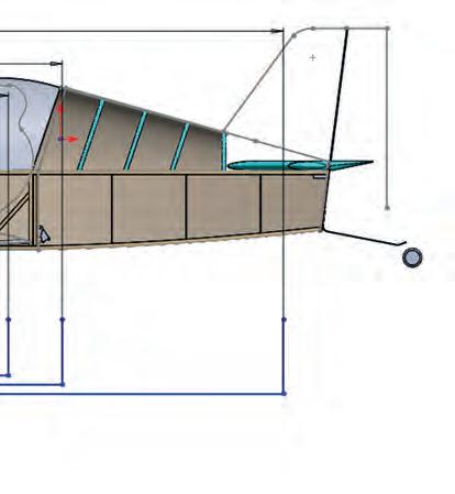
Adding up the component weights is of course easy, but to work out the empty CofG we need to determine all the moment arms of the components. To do this, we first must assume a datum point. For those unfamiliar, the datum can be literally anywhere lengthways (perpendicular to the longitudinal axis), though placing it ahead of the aircraft makes things easier as it avoids having to deal with both positive and negative signs. In our case I’ve arbitrarily set the datum one metre ahead of the firewall. So, let’s start by finding the arm lengths for the following.
Powerplant Fuel Tank Battery
Pilot
Estimate fuselage CG (structure only)
Estimate wing CG (structure only)
Estimate horizontal CG
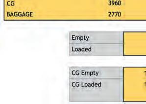
Baggage (Considered how much you want)
Having determined the arm lengths by measuring our three-view, we must now estimate what the weights of the above items will be – this is a little harder. You could determine the approximate weight of the fuselage by determining the amount of material being used and account for landing gear, hardware and so on, which is basically what I have done. This will give us an approximate empty weight which we can then compare with our payload requirements to give a gross weight. Similar-sized aircraft have been built around the 100120kg range (this is where research really helps). It will be in the detail design that I can then work on various parts and pieces to possibly bring the empty weight down.
This is one method of doing it. I know through studying similar aircraft designs that for the wing area this aircraft will have, a 250kg gross weight would give a sensible wing loading and stall speed. Another approach would be to start with an intended stall speed and a projected max gross weight, and use these to work out the wing area I need, based on a realistic value of the max lift coefficient. Of course, the weight, the wing area, aspect ratio, and overall drag will have a major effect on the aircraft’s performance with a given powerplant. You may need to go around the design loop several times over before you find a combination that will work for you.
Have a look at table 1, below, where I have added up the various items from our list above. This is where I could oversaturate the article with maths, but as mentioned above, to determine things like fuselage weight, I simply determined the approximate amount of material being used, calculated the volume, and then multiplied by the density of the material. As my design develops within Solidworks, I can assign a material to each component which will help me keep on top of my W&B, this is one of the benefits of computer aided design. You can make manual calculations to get a pretty good estimate though.


For example, I know I will need four longerons in the fuselage that will be produced from sitka spruce. From studying various similar designs we know that 20x20mm longerons will provide more than adequate strength for an aircraft of these dimensions and weight. I anticipate that when we begin the stress work, later, I will probably find that the 20x20mm spruce is over generous and we could come down to something more like 15x15mm, which will reduce our empty weight. It’s better to overestimate our weights at this stage than to underestimate them, otherwise we risk building an aeroplane that turns out much heavier than expected and consequently are either understrength or short on performance.
So, from our drawing we can see that each longeron will need to be about (remember these are estimates) 3.8 metres in lengths, so:
Longeron Volume = (0.02m x 0.02m) x 3.9m = 0.00156
Sitka Spruce Density = 347 kg/cubic metre.
Thus, one of our longerons should weigh approximately 0.00156 x 347 = 0.54 kg, or 540 grams.
In a similar way we could work out the weights of the ply fuselage sides, the uprights, firewall, bulkheads, nuts and bolts, and the control system.
The much simpler and less accurate way would be to assume the weights of the components. In that case, for example, we’ve assumed our aircraft has a gross weight of 250kg with a 130kg payload. The empty weight is therefore 250-130 = 120kg. If the planned engine installation weighs 35kg that would mean that ‘firewall aft’ our aircraft must weigh only 250-35- 130 = 85kg.
Given this total for the airframe, dividing out our 85kg, let’s estimate that our wings weigh 20kg each, our tail weighs 5kg, and our fuselage weighs 40kg. Pretty wild assumptions, but quite possibly within a good enough ballpark to give sensible estimates on W&B. Of course, these assume ready-to-fly weights, meaning that the fuselage is fully equipped with instruments, seats, fuel tank, undercarriage etc. This method will only work well when you try and design the sub-assemblies to your predicted weights, i.e., if your wing design looks like it’s target 20kg. That could mean, for example, sacrificing a folding wing idea and going for a one-piece wing, or substituting a strut-braced wing for a cantilever job.
Weight & Balance
Now that I have determined my arm lengths and my estimate on the design’s weight, I can now go on to determine the estimated location of my empty weight CofG. Basically, you have to multiply the weight of each component by the distance from the centre of gravity of the component from the datum, to give the moment of the component about the datum. Add the moments from all the components together, then divide the total moment by the total of the weights of the components to give the distance of the aircraft’s empty CofG from the datum line. Aircraft owner / operators should know how to do this already, so I won’t go into this further here!
Having calculated this through, I have determined that my empty CofG is just aft of the main gear. That’s good, as it’s about where I needed it to be. Now that I have a good estimate on my aircraft’s empty weight and CofG, I can use the LAA’s W&B spreadsheet (see LAA website > Engineering > Designing Aircraft > Preliminary Design) and have a play around and see how far forward and aft I can get the CofG by changing pilot, fuel and baggage weights for worst fore / aft CofG cases. As a first shot, these need to be within 20 to 33% of the wing chord. You may notice if you check my calculations that I also check the situation with the aircraft with a full fuel tank and no one in the cockpit. This is to be sure that even with a full tank, the aeroplane won’t tip on its nose without a pilot on board! Details like that are important and easily missed. You can also see that while I assumed a design gross weight of 250kg, my 116.5kg empty gives just over my 130kg target payload. This is through a combination of educated guess work and accurate measurements and predictions of weight. I hope to bring down my empty weight slightly to account for the added weight that is inevitably gained during most aircraft builds.
I hope you are enjoying this simplistic approach to aircraft design. There are a number of books which go into much greater detail than I can here for these articles. Hiscocks’ Design of Light Aircraft is a good starting point, as well as Bud Evans’ Lightplane Designers Handbook Next time, we will populate our Detailed Specification and determine some basic stability parameters. ■
The Alpi P300R sub 600Kg High Performance Light Sport Aircraft
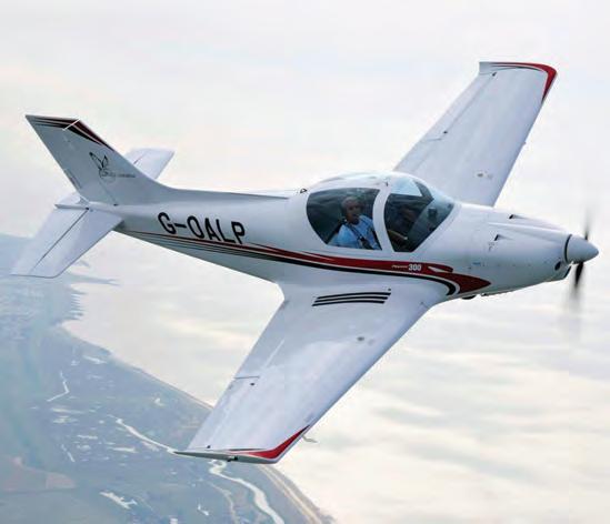
Probably the best in class and made from sustainable materials Fun, Fast and Affordable. Book yours for 2022! Find out more at: www.flypioneer.uk
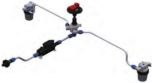
ANDAIR FUEL SYSTEM COMPONENTS COMBINE MODULAR DESIGN, SUPERB QUALITY AND THE FLEXIBILITY TO SUIT ANY AIRCRAFT BUILD PROJECT.
Having built a reputation for excellence in the design and manufacture of light aircraft fuel system components within the amateur-build aircraft sector, Andair has now established a significant presence in the commercial aviation market as well. www.andair.co.uk