3.0
MONORAIL MR
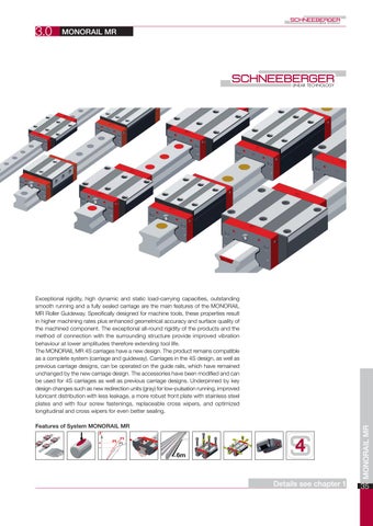
Features of System MONORAIL MR
Details see chapter 1
MONORAIL MR
Exceptional rigidity, high dynamic and static load-carrying capacities, outstanding smooth running and a fully sealed carriage are the main features of the MONORAIL MR Roller Guideway. Specifically designed for machine tools, these properties result in higher machining rates plus enhanced geometrical accuracy and surface quality of the machined component. The exceptional all-round rigidity of the products and the method of connection with the surrounding structure provide improved vibration behaviour at lower amplitudes therefore extending tool life. The MONORAIL MR 4S carriages have a new design. The product remains compatible as a complete system (carriage and guideway). Carriages in the 4S design, as well as previous carriage designs, can be operated on the guide rails, which have remained unchanged by the new carriage design. The accessories have been modified and can be used for 4S carriages as well as previous carriage designs. Underpinned by key design changes such as new redirection units (gray) for low-pulsation running, improved lubricant distribution with less leakage, a more robust front plate with stainless steel plates and with four screw fastenings, replaceable cross wipers, and optimized longitudinal and cross wipers for even better sealing.
35
36
Page number
Overview of types, sizes and available options Product overview MR Rails Product overview MR Carriages
3.2
C
A
//
Technical data and options
// D,E C
B2 D
3.3
E
MR Buildsize 25 MR Buildsize 30 MR Buildsize 35 MR Buildsize 45 MR Buildsize 55 MR Buildsize 65 MR Buildsize 100
Accessories MONORAIL MR Accessories overview MR Rails accessory details MR Carriages accessory details
3.4
Order key
38 38 39
40 40 42 44 46 48 50 52
54 54 55 58
61 Order key MR Rails Order key MR Carriages
61 61
MONORAIL MR
3.1
37
3.1
Overview of types, sizes and available options
MR Rails
Product overview MR Rails
N standard
ND standard, through hardened
Size 25
MR S 25-N
MR S 25-ND
Size 30
MR S 30-N
NU with tapped holes at the bottom
NUD C with tapped holes, for cover strip through hardened
CD for cover strip, through hardened
Buildsizes / Rail build forms MR S 25-NU
MR S 25-C
MR S 25-CD
MR S 30-NU
Size 35
MR S 35-N
MR S 35-ND
MR S 35-NU
Size 45
MR S 45-N
MR S 45-ND
MR S 45-NU
MR S 35-NUD
MR S 45-C
MR S 35-C
Size 55
MR S 55-N
MR S 55-NU
MR S 55-C
Size 65
MR S 65-N
MR S 65-NU
MR S 65-C
Size 100
MR S 100-N
Features
•
Screwable from above
•
Screwable from below Small assembly effort
•
Great single-part system length
• • •
Usable for bombardment with metal chips
•
For the support of metal covers
• • • •
•
•
• •
•
Available options for MR Rails
Details see chapter 2
Accuracy
Straightness
Reference side
Coating
Highly accurate
Standard
Ref. at bottom
None
Very accurate
Ref. on top
Hard chromium
Accurate Standard
Available accessories for MR Rails Plugs
38
Cover strips
Details see chapter 3.3 Assembly tools
3.1
Overview of types, sizes and available options
MR Carriages
Product overview MR Carriages
A standard
B standard, long
C compact, high
D compact, high, long
E compact, high, for lateral fixation
MR W 25-E
F compact
G compact, long
P standard, extra long
Buildsizes / Carriage build forms Size 25
MR W 25-A
MR W 25-B
MR W 25-C
MR W 25-D
Size 30
MR W 30-A
MR W 30-B
MR W 30-C
MR W 30-D
Size 35
MR W 35-A
MR W 35-B
MR W 35-C
MR W 35-D
MR W 35-E
MR W 25-F
MR W 25-G
MR W 30-F
MR W 30-G
MR W 35-F
MR W 35-G
Size 45
MR W 45-A
MR W 45-B
MR W 45-C
MR W 45-D
MR W 45-F
MR W 45-G
Size 55
MR W 55-A
MR W 55-B
MR W 55-C
MR W 55-D
MR W 55-F
MR W 55-G
Size 65
MR W 65-A
MR W 65-B
MR W 65-C
MR W 65-D
Size 100
MR W 100-A
MR W 100-B
MR W 65-P
Features Screwable from above
•
•
Screwable from below
•
•
•
•
•
• •
Screwable from the side
•
For high loads and moments For medium loads and moments
•
•
•
•
•
•
•
For limited installation space
• •
Available options for MR Carriages
•
•
Details see chapter 2
Accuracy
Load
Reference side
Coating
Highly accurate
Low
Ref. at bottom
None
Very accurate
Medium
Ref. on top
Accurate
Hard chromium
High
Standard Lube connections
Left center
Upper left side
Oil protect
Right center
Upper right side
Grease protect
Top left
Left side
Full greasing
Top right
Lower left side
Right side S10+S12+S13+S20+S22+S23
Lower right side
locked using threaded pins
S32+S33+S42+S43
locked using threaded pins
Available accessories for MR Carriages Additional wipers Metal wiper
Bellows Lube nippels
Details see chapter 3.3 and 2.1 Assembly rails Lube adapters
Lubrication plates
MONORAIL MR
Lubrication
39
3.2
Technical data and options
MR Size 25
MR S 25 Drawings
Clearance for end piece assembly
= Locating side = Marked side
MR W 25 Drawings
C3 A
M3x4
O-ring 6,75x1,78
M3x4
L
La
L2
L6
L1 C4
L
L6
La
C7 L1
47
47
10 6
C7
10 6
C4
L
La
L6
L2
C1
J A
O-ring 6,75x1,78
M3x4
C4
L1
M6x6
B2
B2
C7
O-ring 6,75x1,78
11 10 6
10
O
9
J A
J
45° B2
E
B 7,5
M6
18
9
C,D,F,G M6
B N C1
C1 6,5
C3 O
M6x6 C3
M8 6,8
M6x6
A,B O
B N
47
MR W 25 Rigidity diagram
= Locating side
MR W 25 Load rating Tensile load
C/C 0 Deformation δ [μm]
C/C 0 MR W 25 A,C,E,F
MQ /M0Q MLM0L
MR W 25 B,D,G
C/C 0
40
Compressive load
Load F [kN]
ML /M0L
3.2
Technical data and options
MR Size 25
MR S 25 Dimensions
MR S 25-N
MR S 25-ND
MR S 25-NU
MR S 25-C
B1:
Rail width
23
23
23
23
MR S 25-CD 23
J1:
Rail height
24.5
24.5
24.5
24.5
24.5
L3:
Rail length max.
6000
1500
6000
3000
1500
L4:
Spacing of fixing holes
30
30
30
30
30
L5/L10: Position of first/last fixing hole
13.5
13.5
13.5
13.5
13.5
Gew.: Rail weight, specific (kg/m)
3.4
3.4
3.8
3.3
3.3
Available options for MR S 25
MR W 25 Dimensions and capacities
MR W 25-A
MR W 25-B
MR W 25-C
MR W 25-D
MR W 25-E
MR W 25-F
MR W 25-G
A: System height
36
36
40
40
40
36
36
B: Carriage width
70
70
48
48
57
48
48
B2: Distance between locating faces
23.5
23.5
12.5
12.5
17
12.5
12.5
C1: Position of center front lube hole
5.5
5.5
9.5
9.5
9.5
5.5
5.5
C3: Position of lateral lube hole
3.5
3.5
7.5
7.5
7.5
3.5
3.5
C4: Position of lateral lube hole
13
24.2
18
21.7
18
18
21.7
C7: Position of top lube hole
12
23.2
17
20.7
17
17
20.7
J: Carriage height
29.5
29.5
33.5
33.5
33.5
29.5
29.5
L: Carriage length
88
110
88
110
88
88
110
La: Cross wiper spacing*
83
106
83
106
83
83
106
L1: Exterior fixing hole spacing
45
45
35
50
35
35
50
L2: Interior fixing hole spacing
40
40
-
-
35
-
-
L6: Steel body length
60
79.4
57
79.4
57
57
79.4
N: Lateral fixing hole spacing
57
57
35
35
-
35
35
O: Reference face height
7.5
7.5
7.5
7.5
15
7.5
7.5
C0: Static load capacitiy (N)
49800
70300
49800
70300
49800
49800
70300
C100: Dynamic load capacity (N)
27700
39100
27700
39100
27700
27700
39100
M0Q: Static cross moment capacity (Nm) 733
1035
733
1035
733
733
1035
M0L: Static longitud. moment capacity (Nm) 476
936
476
936
476
476
936
MQ: Dyn. cross moment capacity (Nm) 408
576
408
576
408
408
576
ML: Dyn. longitud. moment capacity (Nm) 265
521
265
521
265
265
521
Gew: Carriage weight (kg)
0.9
0.6
0.7
0.7
0.5
0.6
0.7
Note: *Required to determine the rail length from the projected travel distance
Available options for MR W 25
MONORAIL MR
Capacities and weights
41
3.2
Technical data and options
MR Size 30
MR S 30 Drawings 15
11
J1
N 9
L5
L10
L4
B1
L30-2
15
J1
NU M8
L5
B1
L4
= Locating side = Marked side
L10
L30-2
MR W 30 Drawings B N
C,D,F,G 10
M8
A
10 6
O-ring 6,75x1,78
M6x6
L
L6
L1
La
C7
M6x6
C4
L
La
L6
L2
C4
L1
O
B2
15
10 6
C7
O-ring 6,75x1,78
J
9 A
J
45° B2
C1
M6x6 C3
C1 7,5
M6x6
A,B M10 8,5
19 O
C3
B N
= Locating side 57
57
MR W 30 Rigidity diagram
MR W 30 Load rating Tensile load
C/C 0
Deformation δ [μm]
15
C/C 0
10 5 -40
-30
-20
-10
MR W 30 A,C,F
0
10 -5
20
30
MQ /M0Q MLM0L
MR W 30 B,D,G
-10
C/C 0
-15
42
Compressive load
Load F [kN]
ML /M0L
3.2
Technical data and options
MR Size 30
MR S 30 Dimensions
MR S 30-N
MR S 30-NU
B1:
Rail width
28
28
J1:
Rail height
28
28
L3:
Rail length max.
6000
6000
L4:
Spacing of fixing holes
40
40
L5/L10: Position of first/last fixing hole
18.5
18.5
Gew.: Rail weight, specific (kg/m)
4.6
5.2
Available options for MR S 30
MR W 30 Dimensions and capacities
MR W 30-A
MR W 30-B
MR W 30-C
MR W 30-D
MR W 30-F
MR W 30-G
A: System height
42
42
45
45
42
42
B: Carriage width
90
90
60
60
60
60
B2: Distance between locating faces
31
31
16
16
16
16
C1: Position of center front lube hole
6
6
9
9
6
6
C3: Position of lateral lube hole
6
6
9
9
6
6
C4: Position of lateral lube hole
16
26.5
22
22.5
22
22.5
C7: Position of top lube hole
16
26.5
22
22.5
22
22.5
J: Carriage height
35.5
35.5
38.5
38.5
35.5
35.5
L: Carriage length
108
129
108
129
108
129
La: Cross wiper spacing*
103
124
103
124
103
124
L1: Exterior fixing hole spacing
52
52
40
60
40
60
L2: Interior fixing hole spacing
44
44
-
-
-
-
L6: Steel body length
70
91
70
91
70
91
N: Lateral fixing hole spacing
72
72
40
40
40
40
O: Reference face height
8
8
8
8
8
8
C0: Static load capacitiy (N)
74900
98500
74900
98500
74900
98500
C100: Dynamic load capacity (N)
39500
48900
39500
48900
39500
48900
M0Q: Static cross moment capacity (Nm) 1332
1751
1332
1751
1332
1751
M0L: Static longitud. moment capacity (Nm) 966
1614
966
1614
966
1614
MQ: Dyn. cross moment capacity (Nm) 702
869
702
869
702
869
ML: Dyn. longitud. moment capacity (Nm) 510
801
510
801
510
801
Gew: Carriage weight (kg)
1.5
0.9
1.2
0.8
1.0
1.1
Note: *Required to determine the rail length from the projected travel distance
Available options for MR W 30
MONORAIL MR
Capacities and weights
43
3.2
Technical data and options
MR Size 35
MR S 35 Drawings
Clearance for end piece assembly
Locating side Marked side
MR W 35 Drawings
C1
M8
C3
11
M6x6
A
B2 M6x6
O-ring 6,75x1,78
= Locating side
10 6
M6x6
L
La
L6
C4
L2
L
La
L1
L6
C7
C7
10 6
C4
L
La
L6
L2
68
12
J
O
12 A
O-ring 6,75x1,78
M6x6
C4
L1
M8
E
B
B2
C7
O-ring 6,75x1,78
15 10 6
C,D,F,G
L1
45° B2
J
A
12
C3 O
M6x6
N C1
M10 8,5
C1 10
M6x6
B
A,B
O
23,5
J
C3
B N
68
68
MR W 35 Rigidity diagram
MR W 35 Load rating Tensile load
C/C 0 Deformation δ [μm]
C/C 0 MR W 35 A,C,E,F
MQ /M0Q MLM0L
MR W 35 B,D,G
C/C 0
44
Compressive load
Load F [kN]
ML /M0L
3.2
Technical data and options
MR Size 35
MR S 35 Dimensions
MR S 35-N
MR S 35-ND
MR S 35-NU
MR S 35-NUD
MR S 35-C
B1:
Rail width
34
34
34
34
34
J1:
Rail height
32
32
32
32
32
L3:
Rail length max.
6000
1500
6000
1500
6000
L4:
Spacing of fixing holes
40
40
40
40
40
L5/L10: Position of first/last fixing hole
18.5
18.5
18.5
18.5
18.5
Gew.: Rail weight, specific (kg/m)
6.5
6.5
7.1
7.1
6.3
Available options for MR S 35
MR W 35 Dimensions and capacities
MR W 35-A
MR W 35-B
MR W 35-C
MR W 35-D
MR W 35-E
MR W 35-F
MR W 35-G
A: System height
48
48
55
55
55
48
48
B: Carriage width
100
100
70
70
76
70
70
B2: Distance between locating faces
33
33
18
18
21
18
18
C1: Position of center front lube hole
7
7
14
14
14
7
7
C3: Position of lateral lube hole
7
7
14
14
14
7
7
C4: Position of lateral lube hole
17
30.5
23
25.5
23
23
25.5
C7: Position of top lube hole
14
27.5
20
22.5
20
20
22.5
J: Carriage height
40
40
47
47
47
40
40
L: Carriage length
116
143
116
143
116
116
143
La: Cross wiper spacing*
111
138
111
138
111
111
138
L1: Exterior fixing hole spacing
62
62
50
72
50
50
72
L2: Interior fixing hole spacing
52
52
-
-
50
-
-
L6: Steel body length
80
103
76
103
76
76
103
N: Lateral fixing hole spacing
82
82
50
50
-
50
50
O: Reference face height
8
8
8
8
22
8
8
C0: Static load capacitiy (N)
93400
128500
93400
128500
93400
93400
128500
C100: Dynamic load capacity (N)
52000
71500
52000
71500
52000
52000
71500
M0Q: Static cross moment capacity (Nm) 2008
2762
2008
2762
2008
2008
2762
M0L: Static longitud. moment capacity (Nm) 1189
2214
1189
2214
1189
1189
2214
MQ: Dyn. cross moment capacity (Nm) 1118
1537
1118
1537
1118
1118
1537
ML: Dyn. longitud. moment capacity (Nm) 662
1232
662
1232
662
662
1232
Gew: Carriage weight (kg)
2.2
1.5
2.0
1.8
1.8
1.6
1.6
Note: *Required to determine the rail length from the projected travel distance
Available options for MR W 35
MONORAIL MR
Capacities and weights
45
3.2
Technical data and options
MR Size 45
MR S 45 Drawings
Clearance for end piece assembly
Locating side Marked side
MR W 45 Drawings
A,B
18
B2 10 6
O-ring 6,75x1,78
M6x6
M6x6
C4
L
La
L6
L1 C4
L6
La L
L1 L2
C7
C7
O-ring 6,75x1,78
C1
A
A
18 10 6
M10
J
15
31 J
45° B2
C,D,F,G
O
M6x6 C3
C1 11
M6x6
B N
M12 10,5
O
C3
B N
= Locating side
84
84
MR W 45 Rigidity diagram
MR W 45 Load rating Tensile load
C/C 0 Deformation δ [μm]
C/C 0 MR W 45 A,C,F
MQ /M0Q MLM0L
MR W 45 B,D,G
C/C 0
46
Compressive load
Load F [kN]
ML /M0L
3.2
Technical data and options
MR Size 45
MR S 45 Dimensions
MR S 45-N
MR S 45-ND
MR S 45-NU
MR S 45-C
B1:
Rail width
45
45
45
45
J1:
Rail height
40
40
40
40
L3:
Rail length max.
6000
1500
6000
6000
L4:
Spacing of fixing holes
52.5
52.5
52.5
52.5
L5/L10: Position of first/last fixing hole
25
25
25
25
Gew.: Rail weight, specific (kg/m)
10.8
10.8
11.8
10.6
Available options for MR S 45
MR W 45 Dimensions and capacities
MR W 45-A
MR W 45-B
MR W 45-C
MR W 45-D
MR W 45-F
MR W 45-G
A: System height
60
60
70
70
60
60
B: Carriage width
120
120
86
86
86
86
B2: Distance between locating faces
37.5
37.5
20.5
20.5
20.5
20.5
C1: Position of center front lube hole
8
8
18
18
8
8
C3: Position of lateral lube hole
8
8
18
18
8
8
C4: Position of lateral lube hole
21.25
38.75
31.25
38.75
31.25
38.75
C7: Position of top lube hole
17
34.5
27
34.5
27
34.5
J: Carriage height
50
50
60
60
50
50
L: Carriage length
145
180
145
180
145
180
La: Cross wiper spacing*
140
175
140
175
140
175
L1: Exterior fixing hole spacing
80
80
60
80
60
80
L2: Interior fixing hole spacing
60
60
-
-
-
-
L6: Steel body length
100
135
100
135
100
135
N: Lateral fixing hole spacing
100
100
60
60
60
60
O: Reference face height
10
10
10
10
10
10
C0: Static load capacitiy (N)
167500
229500
167500
229500
167500
229500
C100: Dynamic load capacity (N)
93400
127800
93400
127800
93400
127800
M0Q: Static cross moment capacity (Nm) 4621
6333
4621
6333
4621
6333
M0L: Static longitud. moment capacity (Nm) 2790
5161
2790
5161
2790
5161
MQ: Dyn. cross moment capacity (Nm) 2577
3527
2577
3527
2577
3527
ML: Dyn. longitud. moment capacity (Nm) 1556
2874
1556
2874
1556
2874
Gew.: Carriage weight (kg)
4.3
3.0
4.0
2.3
3.1
3.2
Note: *Required to determine the rail length from the projected travel distance
Available options for MR W 45
MONORAIL MR
Capacities and weights
47
3.2
Technical data and options
MR Size 55
MR S 55 Drawings
Clearance for end piece assembly
Locating side Marked side
MR W 55 Drawings
M14 12,5
20 10 6
B2 M6x6
10 6
O-ring 6,75x1,78
M6x6
C4
C4
L6 La L
L1
L6 La L
L2
C7
C7
O-ring 6,75x1,78
L1
A
A
J
35 J
45° B2
M12 19
C3 O
M6x6
18
C1 13,5
C3
O
M6x6
C,D,F,G
B N C1
A,B
B N
98
= Locating side
98
MR W 55 Rigidity diagram
MR W 55 Load rating Tensile load
C/C 0
Deformation δ [μm]
30
C/C 0
20 10 -200
-150
-100
-50
MR W 55 A,C,F
0
50 -10
100
150
MQ /M0Q MLM0L
MR W 55 B,D,G
-20
C/C 0
-30
48
Compressive load
Load F [kN]
ML /M0L
3.2
Technical data and options
MR Size 55
MR S 55 Dimensions
MR S 55-N
MR S 55-NU
B1:
Rail width
53
53
MR S 55-C 53
J1:
Rail height
48
48
48
L3:
Rail length max.
6000
6000
6000
L4:
Spacing of fixing holes
60
60
60
L5/L10: Position of first/last fixing hole
28.5
28.5
28.5
Gew.: Rail weight, specific (kg/m)
15.2
16.6
14.9
Available options for MR S 55
MR W 55 Dimensions and capacities
MR W 55-A
MR W 55-B
MR W 55-C
MR W 55-D
MR W 55-F
MR W 55-G
A: System height
70
70
80
80
70
70
B: Carriage width
140
140
100
100
100
100
B2: Distance between locating faces
43.5
43.5
23.5
23.5
23.5
23.5
C1: Position of center front lube hole
9
9
19
19
9
9
C3: Position of lateral lube hole
9
9
19
19
9
9
C4: Position of lateral lube hole
25.75
46.75
35.75
46.75
35.75
46.75
C7: Position of top lube hole
21.5
42.5
31.5
42.5
31.5
42.5
J: Carriage height
57
57
67
67
57
57
L: Carriage length
172
214
172
214
172
214
La: Cross wiper spacing*
167
208
167
208
167
208
L1: Exterior fixing hole spacing
95
95
75
95
75
95
L2: Interior fixing hole spacing
70
70
-
-
-
-
L6: Steel body length
120
162
120
162
120
162
N: Lateral fixing hole spacing
116
116
75
75
75
75
O: Reference face height
12
12
12
12
12
12
C0: Static load capacitiy (N)
237000
324000
237000
324000
237000
324000
C100: Dynamic load capacity (N)
131900
180500
131900
180500
131900
180500
M0Q: Static cross moment capacity (Nm) 7771
10624
7771
10624
7771
10624
M0L: Static longitud. moment capacity (Nm) 4738
8745
4738
8745
4738
8745
MQ: Dyn. cross moment capacity (Nm) 4325
5919
4325
5919
4325
5919
ML: Dyn. longitud. moment capacity (Nm) 2637
4872
2637
4872
2637
4872
Gew: Carriage weight (kg)
6.8
4.5
6.1
3.7
4.8
5.0
Note: *Required to determine the rail length from the projected travel distance
Available options for MR W 55
MONORAIL MR
Capacities and weights
49
3.2
Technical data and options
MR Size 65
MR S 65 Drawings
Clearance for end piece assembly
Locating side Marked side
MR W 65 Drawings
O-ring
O-ring
O-ring
Locating side
MR W 65 Rigidity diagram
MR W 65 Load rating Tensile load
C/C 0
Deformation δ [μm]
30
MR W 65 A,C
20 10 -200
-150
-100
-50
C/C 0 MQ /M0Q
MR W 65 B,D
0
50 -10
100
150
MLM0L MR W 65 P
-20
C/C 0
-30
50
Compressive load
Load F [kN]
ML /M0L
3.2
Technical data and options
MR Size 65
MR S 65 Dimensions
MR S 65-N
MR S 65-NU
B1:
Rail width
63
63
MR S 65-C 63
J1:
Rail height
58
58
58
L3:
Rail length max.
6000
6000
6000
L4:
Spacing of fixing holes
75
75
75
L5/L10: Position of first/last fixing hole
36
36
36
Gew.: Rail weight, specific (kg/m)
22.8
24.5
22.5
Available options for MR S 65
MR W 65 Dimensions and capacities
MR W 65-A
MR W 65-B
MR W 65-C
MR W 65-D
MR W 65-P
A: System height
90
90
90
90
90
B: Carriage width
170
170
126
126
170
B2: Distance between locating faces
53.5
53.5
31.5
31.5
53.5
C1: Position of center front lube hole
13
13
13
13
13
C3: Position of lateral lube hole
13
13
13
13
13
C4: Position of lateral lube hole
31.75
58
51.75
53
48.5
C7: Position of top lube hole
27.75
54
47.75
49
44.5
J: Carriage height
76.2
76.2
76.2
76.2
76.2
L: Carriage length
207
260
207
260
331
La: Cross wiper spacing*
201.5
254
201.5
254
324.8
L1: Exterior fixing hole spacing
110
110
70
120
200
L2: Interior fixing hole spacing
82
82
-
-
200
L6: Steel body length
148.5
201
148.5
201
272
N: Lateral fixing hole spacing
142
142
76
76
142
O: Reference face height
15
15
15
15
15
C0: Static load capacitiy (N)
419000
530000
419000
530000
748200
C100: Dynamic load capacity (N)
232000
295000
232000
295000
366000
M0Q: Static cross moment capacity (Nm) 16446
20912
16446
20912
29479
M0L: Static longitud. moment capacity (Nm) 10754
17930
10754
17930
32300
MQ: Dyn. cross moment capacity (Nm) 9154
11640
9154
11640
14429
ML: Dyn. longitud. moment capacity (Nm) 5954
9980
5954
9980
15800
Gew: Carriage weight (kg)
13.5
8.0
10.4
20.3
10.2
Note: *Required to determine the rail length from the projected travel distance
Available options for MR W 65
MONORAIL MR
Capacities and weights
51
3.2
Technical data and options
MR Size 100
MR S 100 Drawings
Locating side Marked side
(Wiper)
MR W 100 Drawings
O-ring
Locating side
MR W 100 Rigidity diagram
MR W 100 Load rating Tensile load
C/C 0
Deformation δ [μm]
30
C/C 0
20 10 -200
-150
-100
-50
MR W 100 A
0
50 -10
100
150
MQ /M0Q MLM0L
MR W 100 B
-20
C/C 0
-30
52
Compressive load
Load F [kN]
ML /M0L
3.2
Technical data and options
MR Size 100
MR S 100 Dimensions
MR S 100-N B1:
Rail width
100
J1:
Rail height
92
L3:
Rail length max.
3000
L4:
Spacing of fixing holes
105
L5/L10: Position of first/last fixing hole
51
Gew.: Rail weight, specific (kg/m)
55.3
Available options for MR S 100
MR W 100 Dimensions and capacities
MR W 100-A
MR W 100-B
A: System height
120
120
B: Carriage width
250
250
B2: Distance between locating faces
75
75
C1: Position of center front lube hole
12.5
12.5
C3: Position of lateral lube hole
12.5
12.5 67
C4: Position of lateral lube hole
40.3
C7: Position of top lube hole
40.3
67
J: Carriage height
100
100
L: Carriage length
296.5
400
L1: Exterior fixing hole spacing
150
200
L2: Interior fixing hole spacing
-
-
L6: Steel body length
204.5
308
N: Lateral fixing hole spacing
220
220
O: Reference face height
20
20
C0: Static load capacitiy (N)
976610
1470000
C100: Dynamic load capacity (N)
401115
605000
M0Q: Static cross moment capacity (Nm) 60645
91471
M0L: Static longitud. moment capacity (Nm) 26143
39432
MQ: Dyn. cross moment capacity (Nm) 24959
37646
ML: Dyn. longitud. moment capacity (Nm) 10759
16229
Gew: Carriage weight (kg)
40.0
27.0
Available options for MR W 100
MONORAIL MR
Capacities and weights
53
3.3
Accessories
Overview
MR Rails accessories overview Accessories
MR S 25
MR S 30
MR S 35
MR S 45
MR S 55
MR S 65
MR S 100
Plugs: Plastic plugs Brass plugs Steel plugs
MRK 25 MRS 25 MRZ 25
MRK 30 MRS 30 MRZ 30
MRK 35 MRS 35 MRZ 35
MRK 45 MRS 45 MRZ 45
MRK 55 MRS 55 MRZ 55
MRK 65 MRS 65 MRZ 65
MRK 100 MRS 100 MRZ 100
Cover strips: Cover strip (spare part) Securing band for cover strip (spare part) End piece for cover strip (spare part)
MAC 25 BSC 25-MAC EST 25-MAC
-
MAC 35 BSC 35-MAC EST 35-MAC
MAC 45 BSC 45-MAC EST 45-MAC
MAC 55 BSC 55-MAC EST 55-MAC
MAC 65 BSC 65-MAC EST 65-MAC
-
Assembly tools: Installation tool for steel plugs Hydraulic cylinder for MWH Installation tool for cover strip
MWH 25 MZH MWC 25
MWH 30 MZH -
MWH 35 MZH MWC 35
MWH 45 MZH MWC 45
MWH 55 MZH MWC 55
MWH 65 MZH MWC 65
MWH 100 MZH -
MR Carriages accessories overview
54
Accessories
MR W 25
MR W 30
MR W 35
MR W 45
MR W 55
MR W 65
MR W 100
Additional wipers: Additional wipers Viton Metal wiper
ZCV 25 ASM 25
ZCV 30 ASM 30
ZCV 35 ASM 35
ZCV 45 ASM 45
ZCV 55 ASM 55
ZCV 65 ASM 65
ZCV 100 ASM 100
Bellows: Bellows Adapter plate for bellows (spare part) End plate for bellows (spare part)
FBM 25 ZPL 25 EPL 25
-
FBM 35 ZPL 35 EPL 35
FBM 45 ZPL 45 EPL 45
FBM 55 ZPL 55 EPL 55
FBM 65 ZPL 65 EPL 65
-
Assembly rails: Assembly rail
MRM 25
MRM 30
MRM 35
MRM 45
MRM 55
MRM 65
MRM 100
Lubrication plates: Lubrication plate
SPL 25-MR
-
SPL 35-MR
SPL 45-MR
SPL 55-MR
SPL 65-MR
-
Front plates: Cross wiper (spare part)
QAS 25-STR
QAS 30-STR
QAS 35-STR
QAS 45-STR
QAS 55-STR
QAS 65-STR
QAS 100-STR
Lube nippels: Hydraulic-type grease nipple straight Hydraulic-type grease nipple 45° Hydraulic-type grease nipple 90° Flush type grease nipple M3 Flush type grease nipple M6 Grease gun for SN 3-T und SN 6-T
SN 6 SN 6-45 SN 6-90 SN 3-T SN 6-T SFP-T3
SN 6 SN 6-45 SN 6-90 SN 6-T SFP-T3
SN 6 SN 6-45 SN 6-90 SN 6-T SFP-T3
SN 6 SN 6-45 SN 6-90 SN 6-T SFP-T3
SN 6 SN 6-45 SN 6-90 SN 6-T SFP-T3
SN 6 SN 6-45 SN 6-90 SN 6-T SFP-T3
SN 6 SN 6-45 SN 6-90 SN 6-T SFP-T3
Lube adapters: Lubrication adapter M8 round-head Lubrication adapter M8 hexagon head Lubrication adapter G1/8 hexagon head Swivel screw connection for pipe d=3 mm Swivel screw connection for pipe d=4 mm Swivel screw connection M6 Swivel screw connection M6 long Swivel screw connection M8 Swivel screw connection M8 long
SA 6-RD-M8 SV 3-D3 SV 6-D4 SV 6-M6 SV 6-M6-L SV 6-M8 SV 6-M8-L
SA 6-RD-M8 SV 6-D4 SV 6-M6 SV 6-M6-L SV 6-M8 SV 6-M8-L
SA 6-RD-M8 SA 6-6KT-M8 SA 6-6KT-G1/8 SV 6-D4 SV 6-M6 SV 6-M6-L SV 6-M8 SV 6-M8-L
SA 6-RD-M8 SA 6-6KT-M8 SA 6-6KT-G1/8 SV 6-D4 SV 6-M6 SV 6-M6-L SV 6-M8 SV 6-M8-L
SA 6-RD-M8 SA 6-6KT-M8 SA 6-6KT-G1/8 SV 6-D4 SV 6-M6 SV 6-M6-L SV 6-M8 SV 6-M8-L
SA 6-RD-M8 SA 6-6KT-M8 SA 6-6KT-G1/8 SV 6-D4 SV 6-M6 SV 6-M6-L SV 6-M8 SV 6-M8-L
SA 6-RD-M8 SA 6-6KT-M8 SA 6-6KT-G1/8 SV 6-D4 SV 6-M6 SV 6-M6-L SV 6-M8 SV 6-M8-L
Accessories
MR Rails accessory details
Plastic plugs MRK plastic plugs are used as a low-cost method of closing off the rail attachment holes. They can be fitted manually with fairly simple tools. Plastic plugs are recommended for use with protected axes or in environments with low levels of contamination, e.g. handling. Quantity supplied: Pack of 25 pcs. Order code: MRK xx xx = Size, sample order: 6 x MRK 65
Brass plugs Brass plugs are used in applications with increased contamination or external temperature influences, e.g., in the case of chip impact or whenever a smooth and gap-free rail surface is required. A hydraulic MWH fitting tool is recommended for correct installation. Order code: MRS xx xx = Size, sample order: 48 x MRS 65
Steel plugs Made of stainless steel, the two-part steel plugs are suitable for applications with greater demands on the mechanical stability of rail surfaces, e.g. when mechanical loads are higher or in open chip spaces. They combine the advantages of simple and very precise installation and a high degree of mechanical stability. Function: The clamping ring lies loosely on the screw head in the hole in the rail. When the slightly conical plug is pressed in, the ring is expanded to establish a positive frictional connection between the plug and the hole in the rail. When fitted, the plug is flush with the rail surface where it ensures that the wipers operate to the optimum degree and have an optimum service life. A hydraulic MWH fitting tool is necessary for correct installation. Order code: MRZ xx xx = Size, sample order: 48 x MRZ 65
MONORAIL MR
3.3
55
3.3
Accessories
MR Rails accessory details
Cover strip (spare part) A SCHNEEBERGER MAC cover strip combines technical functionality with simple handling and neat appearance. Made of stainless spring steel, the strip is suitable for demading applications with increased contamination or external temperature influences. It provides the following advantages: – Reliable fixing along the length as it is clipped into a special groove – Additional fixing of the ends of the strips using locking parts (EST xx-MAC) – Very robust thanks to the substantial thickness of the material – The strip free top surface of the rail can be used to support covers – Can be fitted and removed several times – Protection of the wipers during installation as the rail holes are recessed in the groove – Available in any length up to 30m When ordering guide rails with cover strips, they are included in the scope of supply. Order code: MAC xx-yy xx = Size, yy = Rail length in mm, sample order: 1 x MAC 65-4320
End piece for cover strip (spare part) EST end pieces are used to close the ends of MAC cover strips. To do this, these plastic parts are inserted on both ends of the rail into the gap under the cover strip. Their special design prevents the ends of the cover strip from lifting and reduces the danger of injury on the sharp edges of the cover strip. Order code: EST xx-MAC xx = Size, sample order: 2 x EST 65-MAC
Securing band for cover strip (spare part) The BSC securing band for cover strips is used to secure the ends when mechanical loads are high. To do this, the protruding band ends are cut off at right angles and burr-free, and a fastening thread is fitted to the front face of the rail. Securing bands are used in applications with high vibration levels, with rails in open chip spaces, with rail lengths of less than 600 mm or for vertical fitting and the subsequent risk that EST endpieces could fall out. The securing band also covers the ends of the cover strips and reduces the risk of injury on the sharp corners of the ends. Order code: BSC xx-MAC xx = Size, order example: 2 x BSC 65-MAC
56
Accessories
MR Rails accessory details
Installation tool for cover strip A MWC fitting tool is used to simplify the fitting of an MAC cover strip. At the same time, it ensures that the cover strip sits securely in the rail groove without any gaps. Order code: MWC xx xx = Size, sample order: 1 x MWC 35
Installation tool for steel plugs MRZ and brass plugs MRS An MWH hydraulic cylinder is a single-action block cylinder used to create the required insertion force. A standard hydraulic unit that provides the pressure required for the insertion process is connected to the 1/4“ threaded connection. The hydraulic cylinder fits all sizes of MWH fitting tool and must be ordered separately. Order code: MWH Sample order: 1 x MWH
Hydraulic cylinder for MWH An MZH hydraulic cylinder is a single-action block cylinder used to create the required insertion force. A standard hydraulic unit that provides the pressure required for the insertion process is connected to the 1/4“ threaded connection. The hydraulic cylinder fits all sizes of MWH fitting tool and must be ordered separately. Order code: MZH Sample order: 1 x MZH
MONORAIL MR
3.3
57
3.3
Accessories
MR Carriages accessory details
Additional wiper Viton ZCV additional wipers provide extra protection of the carriages in heavily contaminated environments. Made of Viton® (fluoroelastomer), they are suitable for use with aggressive coolants. As their flexibility allows them to be pushed over the rail cross section, retrofitting is possible without the need to remove the carriage from the rail. ZCV wipers can also be used in combination with ASM metal wipers. Order code: ZCV xx xx = Size, sample order: 2 x ZCV 65
Metal wiper The ASM metal wipers made of stainless steel are used when large, loose particles of dirt on the guideway need to be removed. The radial gap between the wiper and guideway is narrower than in the MR-4S front panel and is therefore designed in such a way that the particles cannot get stuck. The metal wipers are particularly effective when combined with additional ZCV wipers. Order code: ASM xx xx= Size, sample order: 1 x ASM 65
58
Accessories
MR Carriages accessory details
Bellows Standard bellows are available for MONORAIL sizes MR 25 – MR 65, the purpose of which is to provide additional protection against dust and water splashes. The bellows are made of synthetic fabric coated on both sides with plastic. The bellows cover the entire length of the rail and their cross section matches the faceplate of the carriage. The external dimensions of the carriage are thus not exceeded by the bellows. Installation is simple and takes little time. A ZPL adapter plate is required to attach the bellows to the carriage. The adapter plate is screwed to the front plate of the carriage using a central screw. An EPL end plate is screwed to the end face of the rail. The bellows are fastened by two rivets to both the adapter plate and the front plate. Retrofitting can only be realised with induction hardened rails as the rail ends have to be drilled for the attachment of the EPL end plates. When ordering a guideway with bellows, the fixing holes for the end plates are arranged in the rails. Order code: FBM xx-yy xx = Size, yy = Number of folds, sample order: 1 x FBM 65-137
Adapter plate for bellows (spare part) The adapter plate is used to attach the bellows to the carriage and is included with every order for bellows. It is made of black anodized aluminium. On an MR 25 size, the adapter plate is also used for a lateral lubrication connection. The outer contour of the adapter plate corresponds to that of the carriage front plate, the bellows and the end plate. The central fastening screw is included in the scope of supply. Order code: ZPL xx XX = Size, sample order: 2 x ZPL 65
End plate for bellows (spare part) Made of black anodized aluminium, the end plate is used to attach the bellows to the end of the rail. It is included with every order for a set of bellows. The attaching holes must be drilled in the rail if the bellows are to be retrofitted. For this reason, we recommend the use of induction-hardened rails for retrofits. The external dimensions of the end plate correspond to that of the carriage front plate, the bellows and the adapter plate. Both fastening screws are supplied with the end plate. Order code: EPL xx xx = Size, sample order: 2 x EPL 65
MONORAIL MR
3.3
59
3.3
Accessories
MR Carriages accessory details
Assembly rail The assembly rail is required when a carriage has to be removed from the rail and then reinstalled during the installation of the MONORAIL. It is advisable to leave the assembly rail in the carriage to protect the rollers against contamination. If necessary, the two internal carriage attaching screws can be fitted and tightened through the two holes in the assembly rail. Order code: MRM xx xx = Size, sample order: 1 x MRM 65
Lubrication plate An SPL lubrication plate is used wherever long lubrication intervals are required. Thanks to its integral oil reservoir, the rolling elements are supplied with an automatic and uniform supply of lubrication over an extended period. It is ideally used in dry and clean environments as in handling technology or on the ancillary axes of machine tools. The advantages are: – Assured supply of lubrication in any installation position – Long lubrication intervals of up to 5,000 km or 12 months according to use – Refill apertures closed with screws – Reduced outlay on lubrication and accessories – Low environmental impact thanks to minimum consumption of lubricant – Wipers have a long service life as oil is also supplied to the top surface of the rail For maximum travel distances without re-lubrication, the lubrication plates are always used in pairs and the carriages are given an additional filling of grease. The lubrication plates have the same dimensions as the carriage front plates and are installed in front of these. Retrofitting is possible. Additional ZCV wipers must be provided in applications in which particles of dirt can come into contact with the guideways. Order code: SPL xx-MR xx = Size, sample order: 2 x SPL 65-MR
Cross wiper (spare part) The double-lipped cross wipers are subject to natural abrasive wear and must therefore be checked regularly and replaced if necessary. To do this, the front panel is loosened and removed from the front plate. The wiper can then be removed and replaced. Order code: QAS xx-STR xx = Size, sample order: 1 x QAS 65-STR
60
3.4
Order key
Individual guide rails and carriages are ordered in accordance with the order codes described below. Q.v. chapter 2.1 and chapter 3.3 for the order key for accessories. Separate order codes are used in each case for rails, carriages and accessories. This also applies to different versions of rails and carriages. All guide components are supplied individually as standard, i.e. unassembled. If required, SCHNEEBERGER can also supply rails and carriages assembled incl. accessories as complete systems. Please note the ordering instructions in chapter 2.4 if this applies.
Order code for MR Rails 2x
MR S
35
-N
-G1
-KC
-R1
-918
-19
-19
-CN
Quantity Rail Size Type Accuracy Straightness Reference side Rail length L3 Position of first fixing hole L5 Position of last fixing hole L10 Coating
NB Q.v. chapter 3.1 to 3.3 for an overview of types, details of shapes, available options and accessories. Q.v. chapter 2 for a description of the options. If possible, standard lengths are preferred for L3 rail length. These are calculated with the table values in chapter 3.2 using the following formula: L3 = n x L4 + L5 + L10 Standard L5 / L10 = ( L4 / 2 ) - 1,5
L3max.
Order code for MR Carriages 4x
MR W
35
-A
-G1
-V3
-R1
-CN
-S10
-LN
NB Q.v. chapter 3.1 to 3.3 for an overview of types, details of shapes, available options and accessories. Q.v. chapter 2 for a description of the options. When ordering version 4S MR carriages, „(4S)“ is added to the end of the order code.
MONORAIL MR
Quantity Carriage Size Type Accuracy Preload Reference side Coating Lube connection Lubrication as delivered condition
61