
4 minute read
Parts List


500-296
500-010
SB6c only refer to page 18 for SB6w
Assembly Instructions
If you have purchased the SB6w model, please refer to the rear wheel assembly instructions on page 18.
Some factory assembly may have been carried out for you, which may differ slightly from the following instructions.
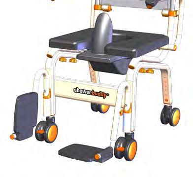
Step 1
Insert Caster Legs (part #500-296 Front and 500-010 rear) into Leg Frame (part #500-001).
SB6 caster legs differ between front & rear. Ensure the correct ones are used Ensure all push pins are set at the same height location to ensure the wheeled base is level and does not rock when sitting on all 4 caster wheels.


Step 2
Sit Seat Frame (part #500-021) on top of Leg Frame (part #500-001) and secure in position by screwing in 4 x Fixing Knobs (part #500-078).
Note: This part may come pre-assembled from the factory.
Step 3
Slide Back Rest Frame (part #500-042) down through Arm Clips (part #500237) and into the Seat Frame (part #500-021). Make sure that push pins are fully depressed before inserting the back rest frame.

Step 4
Fit Left Hand Arm (part #500-043) and Right Hand Arm (part #500-045) by positioning the axle (smaller diameter) part of the tube against the hollow tube across the rear of the Seat Frame (part #500-021) and sliding into this tube.


The Push Pin (part #500-269) will need to be pushed in (depressed) to allow the arms to be fully inserted into this tube.
Once fully inserted the Push Pin will “pop out” into the formed slot to lock the arm into position. This prevents the arm from being removed again without depressing the Push Pin.
Step 5
Note: This part may come pre-assembled from the factory.
Fit Commode Cushion (part #500-020) by positioning onto the Seat Frame (part #500-021) and align the 4 fixing locations.

Fix down using 4 x Seat Fixing Knobs (part #500-079) and tighten.
The Cushion will have the Commode Bucket Connectors (part #500-059) pre-fitted at the factory.
Step 6
The Footrest Assemblies will come pre-assembled from the factory.
To install these assemblies insert the Left and Right hand Footrest Support Tubes (parts #500-253 and #500-254 respectively) into the Seat Frame (part #500-021) as shown on the diagram.
Ensure the location pins are seated inside the location grove shown (part #500-259)

Adjust the Footrest height to suit the user as shown ensuring that the screw lock is fully tightened and the foot supports are level.

Note: The Footrest to Seat Cushion distance can be increased further, if required, by raising the seat height.
To adjust the Seat Height adjust the Caster Legs (part #500-296 front & 500-010 rear) by using the Push Pins in the legs and ensure that the push pins fully engage the height adjustment holes evenly.


Step 7
The Commode Bucket (part #500-072) can be pushed into position from the rear of the chair and is held in position by the Commode Bucket Connectors (part #500-095) pre-fitted to the cushion at the factory.
The Commode Bucket lid is for use after the bucket has been removed from the chair.
A Commode Deflector (part #500-074) is able to be fitted to the Commode Bucket after the bucket is fitted to the chair. The deflector may be fitted after the User is seated to allow easier transfers of the User to and from the chair.


You can also fit the deflector without the bucket by sliding it into the factory fitted clips (part #500-255) on the seat base
The chair is now fully assembled and ready for use.
Operation
Caster Wheels
All caster wheels can be locked and unlocked by depressing the foot brake pedal on each caster wheel. All caster wheels should be locked during the transfer of the user to and from the chair.

The caster wheels should be rotated outwards towards the front and rear of the chair to make the chair more stable during transfers.

Seat Height Adjustment
To raise or lower the seat height depress the push pin in the caster leg as shown and move the caster leg up or down to suit the user height requirement.
Ensure all push pins are set at the same height location to ensure the wheeled base is level and does not rock or feel unstable. The chair must sit on all 4 caster wheels.
Warning
If you find a push pin is not fully engaging or “popping out” into position after use DO NOT use the chair. Consult your supplier for adjustment.
The chair may be adjusted to have a higher seat height at the front and lower at the back to suit user requirements. This can be accommodated by adjusting the front caster leg only to be extended further than the rear caster leg. Under no circumstances should there be more than 1-adjustment position difference between front and rear (approximately 20mm).
In every circumstance the chair must be adjusted with all caster wheels set to touch the ground at the same time otherwise the chair will rock and will not be stable. DO NOT use the chair unless all 4 caster wheels are firmly on the ground.

Footrest / Height Adjustment / Fold Away
The tray style footrests fitted to your chair are not designed to carry user weight. They are designed for a user to rest their feet.
WARNING - DO NOT STAND on the footrest as the chair may become unstable and tip forward causing injury to the user.
To raise or lower the footrests unscrew the locking knob in the footrest supports (parts #500-253 and part #500-254) and move the footrest supports up or down to suit the user height requirement.
Should the user be very tall and require additional seat cushion to footrest adjustment, raise the seat height (as detailed earlier) while having the footrest support at

The footrests can be folded and swung away when not in use or during transfers.
1. Lift the footrest plate and fold it up until
2. Lift footrest assembly and rotate to swing the entire leg out and away should more
To remove completely simply lift away from

