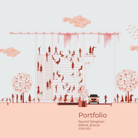
Portfolio Saumil Sanghavi KRVIA, B.Arch 2016-2021
Cirriculum Vitae
Competetions
FOAID “Wood is Good” 2018-2019 Second place | Furniture Design
INTACH Heritage Awards 2018
Second place in city stage | Documentation Competetion
Name
Saumil Sanghavi
Contact Info
Ph. No. : +91-9820265863 Email ID : sanghavisaumil@gmail.com LinkedIN : https://www.linkedin.com/in/ saumil-sanghavi-206635214
Based in Mumbai
Education
Kamla Raheja Vidyanidhi Institute for Architecture (KRVIA) Mumbai University | Bachlor of Architecture | 2016- 2021
Ecole d’architecture Strasbourg
Exchange Program | Design Studio | Nov, 2019
Exibitions
Braj: Architecture of the Parikrama Exibitied at KRVIA | CEPT Library | Kalakriti Art Gallery
Positions and Responsibilities
Film Secretary | Student Council - 2018 Study Trip Incharge | 2016 - 2018 Head of Graphics | Annual Exibition 2018 Student Incharge | Student Work Exibition Class Representative | 2020
Skills
AutoCAD | SketchUp | Rhino | Grasshopper | V-Ray | Adobe Suite | ArchiCAD | Microsoft suite | Sketching | Model Making
Interests
Reading | Photography | Music | Cinema | Travelling
Professional Experience Research Fellow
Research Fellow for Community Based Participation Research and Advocacy PUKAR | July, 2021 - Ongoing
Andres Jaque / Office for Political Innovation Internship | Jan - May, 2020
I am an curious, ambitious, hard working, passionate and collaborative individual who has a keen eye to understanding the underlying systems that govern design. The Portfolio is a compilation of selected works which looks at the attempts at understanding space, the systems that allow for its creation and form across the 5 years of architecture school and attempts to show the rigorous processes followed for each project and how each project has moulded my thought process. I aspire to be a contributing member of society through informed design solutions.
Table of Contents
1
Mumbai Skywalk Project: An extension of everyday life
2
De(Coding) / Re(Coding) Architecture
3
Revitalising the Importance of Golconda Fort
4
Reviving Bodli Gate
5
Reclaiming the Water’s Edge
6
Study Trip Documentation: Braj
7
Internship at Andres Jaque / Office for Political Innovation
8
Smart City and Heritage
9
Between the Lines
10
Sports Centre in Benhram Baug
11
Youth Hostel in Patiala
12
Allied Design - 2
13
Allied Design - 4
14
Material Exploration
15
Study Trip: Patiala, Badami
Mumbai Skywalk Project An Extension of Everyday Life Undergraduate Thesis Guide: Pinkish Shah
The role of infrastructure in nation building is essential and these projects have a very large and long-term effect on not only the economics and mobility of the city, but also on its socio-cultural and environmental fabric. But in practice, these projects are highly insular to their neighbourhoods. The thesis argues that this singular imagination of such projects within the context of a large urban city should be critically revaluated. The thesis attempts to look past this singular imagination of Infrastructure through the lens of the Mumbai Skywalk Project. The Mumbai Skywalk Project was initiated by the MMRDA in 2007 and a total of 36 skywalks have been constructed by various organisations till date. These ‘skywalks’ connect railway stations to nearby important transportation nodes. The thesis acknowledges the existence of these projects within their respective neighbourhoods and consciously attempts to carefully analyse these existing artefacts within their respective neighbourhoods and provide alternative imaginations of these projects. Rather than proposing a new system for the project, the thesis works with the existing Skywalks and works towards their re-integration within their neighbourhoods such that these projects work towards the generation of multi-level urban public space within the neighbourhood and provide alternatives to this singular imagination in the role of Infrastructure and the city.
Right: Exploded Axonometric of the Proposed Design at the Borivali (W) skywalk
“The skywalk’s columns create a nuisance for vehicular movement and impedes it.” says the traffic police stationed at the booth.
The skywalk’s several columns on the wide sidewalk provide liveable spaces for the Naik family.
The project attempts to understad the typology of the skywalk and looks at the relatioship within and underneath these elevated transportation infrastructure systems with everyday life. This is documented through a matrix and several axonometrics talking about the relationship of the skywalk to the built environment and its interaction with everyday life.
There is an acute shortage of direct sunlight into the house due to the proximity of the skywalk. Tubelights need to be switched on even in at noon.
Pramod Bhai uses the skywalk for jogging during off peak hours in the morning.
Top: Axonometric views of several skywalks across the city looking at how everyday life interacts with skywalks Left: Matrix of typologies of all skywalks in MMR region Bottom: Masterplan for Borivali (W) skywalk
The skywalk at Borivali (W) is chosen as the urban intervention. This skywalk due to its rich context , use and relationship to the railway station. The project attempts to create a multilevel urban realm to allow for not only increased interaction of the skywalk with the ground plane but also create a socio-cultural realm along its lenght as a means to diversify the singular imagination of the skywalk. To do this, a part of the road is pedestrianised and mezanine level are created to allow for interactions at multiple levels across the skywalk. A part of the redestrain road is pervious and acts as a bio-swale to allow for water to percolate into the ground. The skywalk opens into an amphitheatre which acts as a focal point of the skywalk at the commercial core of the site. On the other side, the existing pedestrain subway is expanded to create an amphitheatre which responds to the extended plinth of the railway station to create social spaces at the railway station edge. A steel parasol is used as a visual edge to the project which allows for landscape to hang onto. At the skywalk level, the skywalk extends into nearby commercial buildings to create a multi level urban plaza.
Top: Diagrams to understand the Nature of urban roads Right: (Top to Bottom) Ground Floor plan Mezzanine Level plan Skywalk Level plan
Area B
Area A
Area D
Area C
Cross section of Area A
Cross section of Area C
Cross section of Area D
Module Design
Module when Closed
Module when Open
Fixed part of Module
Structural and Services Core of Module
Module furniture layout for food kiosk
Module furniture layout for clothing / accessories kiosk
Multiple staircases are placed across the project and each staircase due to its individual identity through form and color create a local identity which along with the vertical landscape mesh creates a unique space at each instance. The project at the upper levels is occupied by retail modules. These modules are designed to be interactive. The modules allow for several different sorts of retail activities within them and can be also occupied by multiple retail vendors at the same time. It allows for movement through and across it and activates all of its sides. The module when not in use can be closed to reduce its footprint
Top: Seating with an incorporated planter bed; Visually light seating made of wire mesh
and allow for more space at the upper levels. The modules are accompanied by seating spaces designed as well. Multiple different types of seating are designed based on their position of the skywalk.
(De)Coding / (Re)Coding Architecture
A Precast fabricated module construction system is used where all residential modules are bolted onto the structural system of the building.
Semester 9 Bridge Design Studio
Collaborators: Krishna Parmar, Sakshi Kajave, Rutuja Vartak, Vedvrat Kelkar Guide: Sameep Padora, Vami Koticha, Sakshi Ghulati
The studio looked at understanding the form of housing developments in Mumbai through the lens of the Devevlopment Control Regulations. This was studied through the lens of BDD Chawl Worli. Understanding the current DCR and the reulstant formal nature of built space was studied and then multiple stakeholders were identified (BMC, MHADA, Private Developer, Citizens, Activists) and the project was imagined throug hthe lens of these stakeholder priorities. Negotiations were simulated between stakeholders for each stakeholer proposal to understand how each stakeholder responds to each others demands.
4 seperate modules are designed which can be attached onto the existing structure. These modules can be attached anywhere along the building based on the preferences of the residents. The offsets between all units should not be considered in FSI calculation as they are not habitable spaces. TYPE 1 - Rehab Unit - 46.5 sqm TYPE 2 - EWS Unit - 24 sqm TYPE 3 - MIG Unit - 66 sqm TYPE 4 - HIG Unit - 93.5 sqm Recreational Open space
Up: Plan of proposal for the Private Developer
A central green corridor is provided for public is flanked by a commercial retail space on one green corridor is also directly connected to the proposed underground metro station.
use. This e side. This e
The building is designed such that it can accomodate additional units after consuming all FSI on site such that if MHADA needs to increase the number of tenants on site, it can be easily done.
Housing modules are lifted into place by a moving crane on the top.
A large open space is provided which during construction will function as a prefabricated module manufacturing shed and later be public space with amenities as given in the DCR
A seperate Commercial office space block is provided on site to maximise its capital value. This block also has a direct connection to the proposed underground metro station.
The proposed metro station of Worli of Metro line 3 has been realigned
Up: Axonometric view of proposal for the Private Developer
Demand The design of the project should be done in such a way that it can be constructed using prefabrication construction methods to reduce costs through economies of scale. It will increase the pace of the project and allow for faster project completion.
Key Plan
BMC shall not allow the buildings to go highrise as this technique is unfamiliar in mumbai, and in case of fire the prefab construction dont work as an integrated structural unit
A
A 45m high central greenway is proposed o which cuts through all buildings which acts as a spine which also has retail spaces abutting i greenway is also directly connected to the pro metro station
The feasibility of this construction depends on the transportation costs and challenges as the size and nature of the prefabricated units will be limited by the kind of transportation. Also, tenants will only be able to occupy units after the completion of the project as opposed to in-situ construction. The design of the unit and aesthetics should not be compromised because of limitations and reductions in costs as the scale of the project is large and it will serve as an image for the city as a whole.
Up: Stakeholder discussions were simulated to understand the perspectives of all stakeholers on site.
A
on site a green it. This oposed
Down: Master Section
B
C
A large paved surface is provided besides the ground floor which not only acts as a open public space, but also as a staging ground for lifting housing units into place.
The building allosw for future expansion through the addition of modules in the upper voids. This will also ensure a future source of income from the project post construction.
C
B
Master Section
Understanding the formal priorities of each stakeholer eventually led to a concensus proposal after several negotiations between all stakeholders. The concensus proposal is a compromise between all stakeholders for the creation of a built space. Through the concensus proposal, changes to the DCR were also proposed which would make the built form more ideal for all stakeholders on site based on their negotiations. The project did not attempt to create strong architectural design but rather attempted to understand the larger stakeholder negotiations that dictate the formation of our built environment.
12 m
Along 18m road a setback of 12m green open space is provided. Informal market place or regulated vending zone provided within the setback along pedestrian streets.
Rehab Unit - 46.5 sqm MIG Unit - 50 sqm conserved buildings HIG Unit - 75 sqm Recreational Open space Amenities Commercial
Up: Concensus Masterplan proposal
Podium linked through bridg the internal pesestrain street green spaces.
ges along t providing
Down: Axonometric view of proposal for the Private Developer
Angle between two buildings should not be more than 70 degrees to ensure light and ventilation.
Saleable area for the redevelopment will consist of 10% HIG, 35% MIG and 55% Commercial of total saleable BUA.
55 % Comercial and Retail
35 % MIG
10 % HIG
Common balcony space between two units.
Amenities of school and balwadis provided within the cluster.
Mhada will set up a museum to conserve its century-old chawls. In worli, 2 structures will be conserved and will house pictures and archives of BDD and will be used for tourism. The museum will be situated in a large public open space, which during festivals will be used to host large gatherings.
Public parking provided adjacent to the metro station to act as a feeder system to the Metro line.
The proposed Metro 3 line is realigned such that the Worli metro station opens into the BDD Worli Plot.
Revitalising the Importance of Golconda Fort Urban Design - 7
Collaborators: Kashish Singh, Mishti Shah, Jinal Shah, Savlee Tikle, Shrusti Shah, Vedvrat Kelkar Guides: Sonal Sundarajan, George Jacob, Samarth Das
The studio looked at the city of Hyderabad and the precinct of the Golconda fort was chosen as a site for a master plan as a means to allow the precinct to be an important foci for the city again. The master plan while studying the precint also looked at the the fort wall surrounding the precinct which is a 6.5km long path that surrounds the precinct which was largely unused and to re-appropriate the fort wall as an important piece of infrastructure of the modern day.
This region was developed further for the studio
Reviving Bodli Gate Architectural Design - 7
Collaborators: Kashish Singh Guides: Sonal Sundarajan
The project looks at creating a relationship between the fort wall and the ground. A new road is proposed is proposed to pass through the now defunct Bodli Gate. Programtically, the cultural functions of the site as proposed here as the community edge of the fortwall. The project is imagined as a connection of the ground with the Fortwall and allows people to have a varied relationship with the Fortwall and the Moat. The project is wrapped around a large central plaza which forms an amphitheatre to interact with the Moat and Bastion of the Fortwall. The roof of the project gradually rises up from the Central Plaza and reaches the Fortwall. This roof is punctured at several instances to let in natural light into the spaces within the project.
Top: Mapping relationship of all programs and stakeholders Bottom: Masterplan for Bodli Gate
Top: Axonometric view of the Project
N Top: Site plan showing part of project detailed individually
Top: Formal operations on the wall Movement diagram from ground level onto the Fort wall through the project Bottom: Sectional Elevation showing the entire project on either sides of the wall
Top: Basement plan
Top: Section through the Central Public Plaza from the road
Top: Section showing Relationship of the Central Public Plaza and Amphitheatre
Top: Ground Floor plan shoiwng the Central Public Plaza
Top: First Floor plan showing multiple Terraces leading to the Wall
Reclaiming the Water’s Edge Architectural Design - 6 Guide: Mayuri Sisodia
The studio looked at the Institutions of Faith in the Landscapes of Braj. The site is located beside Vishram Ghat on the banks of Yamuna in Mathura. The project looks at re-igniting the relation between the Yamuna river and the River edge. The project looks at the unmediated interface between people and the river where interactions that might not happen at religious ghats can easily happen. The river edge is modified to allow for increased interaction with the river. Stormwater upwards from the site is taken in and treated to remove large debris from the water and introduce it in the river. The project occupies a minimal footprint on site to ensure maximum space is opened up for the public with the central void used for stormwater treatment. A stepped ghat is created on the river edge on one side and a sunken amphitheatre is created on the other side. This alongside the balconies at multiple levels on the project allows for interaction with the river in multiple ways. Through its architectural languange, the project tries to reclaim space for personal interactions with the river.
Right: The matrix shows the relation of physical space with its mythological story and its relations to our personal self.
Top: Figure ground showing density of built form while approaching Vishram Ghat and how the site offers a relief in terms open spaces and vistas of the river. Right: The imagination of space on site.
Right: A drawing showing how various kinds of spaces are formed at the rivers edge and around the building.
Top: The Ground floor plan mediates the relation between the land and the river edge while working around contours of 5m. It is setback from the front and back and occupies a very small footprint to maximise the ground cover for interactions between people and the water’s edge.
Top to Bottom: Longitudinal section thorugh the building showing the relationship of the Ground, Water’s edge and the building. River elevation showing the facade of the building
Study Trip: Braj
3rd year class documentation Collaborators: Shalaka Joshi, Charvi Parakh Guides: Rohan Shivkumar Shirish Joshi
The Third Year Study Trip looked at the documentation of the landscape of Braj in and around the cities of Mathura,Vrindavan,Gokul and Govardhan. This documentation deviated from the cartesian method of documentation through plans, sections and elevations as those drawings tend to only focus on the architectural form and does not look at it’s cultural aspects. Thus inspirations were taken from Mughal miniature paintings and how they flattened and unfolded spaces around each other.
The Exibition has been featured at CEPT in Summer 2019 and Kalakriti Comtemporary Art Gallery in Hyderabad.
A hand-drawn panel of Krishna Janma Bhoomi Pencil on Tracing Sheet 5x 594x841mm
Shiv Taal
It is a 300-year-old ‘kund’ constructed exclusively with sandstone is situated in a relatively isolated locality of Mathura. It as an Akhada on one side and is flanked by railway lines on opposite sides.This isolation creates an atmosphere of solitude.Just like the water of the Kund, the space seems to be frozen in time.Legend states that Shiva was intruiged by Krishna and descended down into this Kund and transformed into a woman by taking a dip in it, enabling him to participate in Krishna’s ‘Rasleela’
A narrow lane on the side leads to a bustling ‘akhada’ where men practice ‘kushti’ and consume ‘bhang’ post practice.
As per legends, when Mughals raided the land, a ‘shivlinga’ in the ground was broken by Aurangzeb.
The water is stagnant and covered with green algae which depicts the lack of ecology and rising levels of pollution. The water level has receded over time.
One of the temples located just outside Shiv Taal is a Krishna mandir. It started as a stone idol which was developed into a tiny temple.
Andres Jaque / Office for Political Innovation Architectural Internship
Mentor: Roberto Gonzales Garcia
A 1:100 model of the Collegio Reggio School was built for an exibition at the Telefonica Foundation hosted by the Foster Foundation in Madrid. Collaborators: Rajvi Anandpara, Shubhankar Bhajekar, Meerati Rana and Mishti Shah Supervisor: Jesus Cortes
A research project was undertaken titled ‘Transscalar Architecture of COVID-19’ The film interrogates territorial divides, the condition of migration and the making of refugeeness, old and new geometries of colonialism, tax justice, access to healthcare, racism and xenophobia, warfare rhetoric, surveillance, urban infrastructures, public spaces, and borders. But also; entanglement, cooperation, inventiveness, engagement, and emerging forms of togetherness Collaborators: Rajvi Anandpara, Shubhankar Bhajekar, Meerati Rana, Mishti Shah, Dristhi Gandhi and Maria Karagianni Supervisor: Andres Jaque, Ivan Munera and Roberto Gonzales Garcia
Source Top to Bottom and Left to Right: Eduardo Anizelli, TPG, KFC, Remo Casilli, Danyalle Khamra, AFP, STR/AFP, TPG, Paul Sancy
A research project was undertaken to study ‘wetness’ in and around the Yangtze river for the 2020 Shanghai Bienalle titled ‘Bodies of Water’ Collaborators: Mishti Shah and Maria Karagianni Supervisor: Andres Jaque, Ivan Munera and Roberto Gonzales Garcia
Source Top to Bottom and Left to Right: Harry Grover Seeley, Dejiang Huang, Laya Skriver, Shuying Goshen, Steven Benson, Voith-seimens, Ekrem Canli, Shu Gao, Du Bin
Smart Cities and Heritage
Student Exchange KRVIA, ENSAS Strausbourg, KIIT Karlsruhe Exchange 2019 Guide: Sebastian Perraul, Shraddha Sejpal Collaborators: Leonie Goertz
The student exchange worked at the idea of a ‘Smart City’ in the context of the heritage of Chandigarh. Sector 56 is a new development aimed at housing the city’s poor. The sector was planned by the Chandigarh Housing Development Board and is planned in a careful manner to allow for the presence of social spaces of several scales in the neighbourhood. The study aimed at analysing the existing fabric of this neighbourhood and to give recommendations that can be implimented under the ‘Smart City Mission’ in Chandigarh. Since there are large families living in each apartment or house, recommendations to expand the space of the home into these open public spaces were given.
Figure Ground
Right; Top to Bottom: Site Analysis Bottom: Morphology of the Housing fabric
Housing Typology
Housing Morphology in the Sector
Social Spaces
Bottom: A exisitng floor plan showing the layout of an individual unit
Top: A view of a temporary pavillion in the open spaces
Since there is lack of space in each apartment with ever expanding families, the space of the corridor has become the extended living spaces for each house. A proposal for expanding this living space into the open space in front of each apartment block as a temporary pavillion was given. These spaces are not used efficiently and creating temporary pavillions can extend the boundaries of the home and allow these spaces to be used well.
Balcony Kitchen Toilet
Room
Social space
1m
2m
4m
Betweel the Lines FOAID Wood is Good ‘18-’19 Competetion entry (2nd prize)
Guide: Ali Baldiwala, Hussain Indorewala, Apurva Parikh Collaborators:Naitik Gala, Yashvi Gala,Asmita Patniak, Rashi Dave, Saivi Shah, Savlee Tikle
The project was about building a multi-functional funrniture out of a given quantity of wood that was provided. The design looked at a compact piece which could expand volumetrically to reveal spaces within. The design also looked at the sectional nature of a wooden log and how to optimise the utilisation of wood. It evolved to be a furniture piece that catered to all age groups of people. The furniture looked at creating seating and standing spaces along with some storage spaces and a small desk for kids.
Plan at 550mm
Front Elevation
Top to Bottom: Drawings made for construction Left: The furniture is imagined as a plane which can open to reveal spaces and be compacted when not in use to save space.
Right: Various iterations of elevations were produced where different parts of it open to serve different functions.
Right: Constructed Furniture at display during FOAID 2018-2019. Bottom: Snippets showing how the furniture transforms.
D2
BY
BW
BU
BR
W6
BP D3
5050
5000
5000
5000
BM W6
BJ
BG
BD
5000
5000
BC
BA
W4
D3
D3 5000
5000
5000
5000
W4 BC
BA
CF C1,C2,C3,C4
CE C5,C6,C7,C8
C9,C10, C11,C12
BD CD C13
CC
CB C14
CA C16
BZ C15
C17,C18,C19, C20,T1,T2,T3 BY
BX C21,C22
BW T4,T5,T6
BV C23,C24,C25,C26
C27,C28
BU T7,T8,T9
BT
BS C29,C30,C31
BR T10,T11,T12
BQ C32,C33,C34
BP T13,T14,T15
BO C35,C36
BN C37,C38,C39
BM T16,T17,T18
C42 SHEET 2
BG
BJ
SHEET 3
T19,T20,T21
BL
C47,C48, C49,C50
BK C40,C41,C43, C44,C45,C46
BJ
BM BI
C59,C60,C61
BH C51,C52,C53,C54
T28,T29,T30
BG T22,T23,T24
C67,C68,C69, C70,C71
BF
T31,T32,T33
BE C55,C56,C57,C58
BA
C67,C68,C69, C70,C71
BD T25,T26,T27
AZ
BP BC T28,T29,T30
AY
C62,C63,C64, BB C65,C66
AX
S1,S3
AW T34,T35,T36,S2
T37,T38,T39
AV C72,C73,C74, C75,C76,C77
AT
AU C78,C79,C80
AS
T43,T44,T45
AR C81,C82,C83
AQ S4
T46,T47,T48
C84,C85,C86, C87,C88,C89
AP
AO
T49,T50,T51
C90,C91,C92, C93,C94,C95
AN
AM
BR
BU
SHEET 2
AL
BW SHEET 1
C98,C99
C96,C97
AK
AJ
T55,T56,T57
T58,T59,T60
AI
AF
T61,T62,T63
C106,C107, C108,C109
AH
AE
C100,C101, AG C102,C103, C104,C105
AD
C112,C113, C114,C115 AB
AC C110,C111
AA T67,T68,T69
T52,T53,54
BY
Right: Ground floor plan with centre lines. Bottom: Front elevation showing the verandah. F6
+150
+150 +0
+0
KIDS PLAY AREA
PLANTER BED
41
42
44 43
C95,C105
+150
D2 CHANGING ROOM 3100X3400
40 38
39
+150
UP
R 150 UP T 300
D1
+3750
D1
34
35
3 2 1 +1950
+3750
+2550
29
30
31
32 28
3 2 1
4
+1350
33
+3150
+1650
DN R 150 T 250
D1
C97
W3
C95
W9
C99
W3
C105
C89 D2 CHANGING ROOM 3000X3400
D1
D1
+3750
C82
W3
C88
W3
+150
D2
DN R 150 T 250
W3
+0
W3
KIDS PLAY AREA
C87
C103 C93
27 23
24
-1600
25
D1
S2
S4
+750
C92
D1
26
W3
BASKETBALL COURT 15000X30100
+0 PLANTER BED
DUCT 7200X1500
C109
C102
22
C115 W2
D1
+150
17
18
19
20 16
W1
S1
C110
C113
+0
14
15 13 12 11
C97,C99
C77,C89
C80,C83
C95,C105
5
6
7
8
T35
T44
T47
T59
T56
T62 +450
C66,C76,C88
C1,C9,C17,C23,C106,C112 C8 T1,T4,T7,T10,T13,T16,T19,T22, T25,T28,T31,T34,T37,T40,T43, T46,T49,T52,T55,T58,T61,T64,T67
T2,T5,T8,T11,T14,T17,T20,T23, T26,T29,T32,T35,T38,T41,T44, T47,T50,T53,T56,T59,T62,T65,T68
F6
4
+450
+450
DN
1
2
3
T27
T42
DN
T45
T48
+450 DN
+450 DN
T57
T54
T51
T60
T63
T66
T69
+450 DN
C13
C16
T3,T6,T9,T12,T15,T18,T21,T24, T27,T30,T33,T36,T39,T42,T45, T48,T51,T54,T57,T60,T63,T66,T69
C14
1
T39
DN
C15
2
T36 +450
3
T33
4
9
UP
6
T30 +450 DN
2 1
5
10
T67
T64
7
T68
T65
8
T32
+450
T24
C94,C104
C5
C67,C78,C81
9
+450 DN
T21
C71,C86
C61
C31,C34
10
T18
C27,C35
C96,C98
C62,C72,C84
C29,C32,C40,C47,C51,C55
11
T15
C90,C100
12
T12
C18,C21,C24,S1, C107,C110,C113
13
T23
F6
T9
C92,C102
C91,C101
14
T20
DN
2 1 T6
C79,C82
C38,C45
C59
C4,C12
C41,C48,C52,C56
15
T11
F6
+450 DN 2 1 T3
C15
C3,C6,C11,C42,C49 ,C53,C57,C64,C69,C74
C2,C7,C10,C63,C68,C73,C85
C19,C22,C25,C108,C111,C114
16
BH
BE
C14
C37,C44
C28,C30,C33,C36,C43, C50,C54,C58,S2,S4
W2 W2
D1
W2
C114
D2
-1050
D1
C112
T61
+150
T8
T5
+450
BI D2
C39,S3
C60
C65,C70,C75,C87 C93,C103
C20,C26,C109,C115
W2
D1 S1 F2 D1 C1 Wa2
D1 1500X900
C111 CHANGING ROOM 4950X3000
17
21
SLOPING SLAB
WALL HEIGHT: 2400
S1 F1 C1 Wa2
D2
HANDICAP TOILET 2550X2550
D2
S1 F1 C1 Wa1
DN
18
UP
19
-1050
10 9 8 7 6 5 4 3 2 1
4 3 2 1
20
W3
21
C100 D3
22
D1
W2
D1 1200X900
W2 +150
W1
W3
C107
C98
C96
W3
DUCT 2550X1000
+450
C106
T58
23
+750
D1
W2
W3
C90
C84 D3
T55
24
W3
SWIMMING POOL 10000X22000
+750
+750
CAFE
W3
+150
D2
C85
C81
R 150 T 300
25
+0
D1
W2
D2
C69
C46
C104
S1 F1 C1 Wa1
+750
C75
S1 F1 C1 Wa1
KITCHEN 3550X9000
PLANTER BED
W4
C74 C64
C86
W1
C101
C108
300MM OVERFLOW DRAIN
C73
W4
S2 F4 C1 Wa3
C78
W4
T52
26
+750
C57
S1 F5 C1 Wa1
+150
W4
C91
-2250 C68
C63
W3
+750
C67
D3
W4
T53
T50
T49
27
D2
+750
PLANTER BED
C83
D1 W2
C94
-250
TOILET 1200x2500
36
D2
D1
D1 W2
D1 C79
C76 1 2 3
+750
W2
S3
37
C71 +750
STORE ROOM 2100X4250
D2
C70
R 150 T 300
W5
C58
DOCTOR'S OFFICE 2 4550X3300
+750
D2
DOCTOR'S OFFICE 1 4550X3750
C56
RECEPTION 6750X6000 D1
C72
C62
T46
28
STORAGE ROOM 4550X2300
+750
S1 F1 1200X900 C1 Wa2 D1 W2
1 2
2 1 UP
R 150 T 300
29
C43
D1
+0
T43
30
C54
+0
W4
C35
PLANTER BED C55
T40
1 2 R 150 T 300
+750 2 1
UP
T41
T38
T37
31
4 3 2 1
R 150 T 300
C50
PLANTER BED
C36
D3
C53
D2
FIRST AID ROOM 4550X4750
+150
W4
C52 C48
+750
S2 F3 C1 Wa1
W4
W4
1 2 R 150 T 300
+750
2 1 UP R 150 T 300
T34
32
+0
C44
DUCT 1200x2000
C46
PLANTER BED
C45
C37
C33
C49 C42
PLANTER BED +0
W7
D5
C41
DN
C51
D3
C47
T31
33
W6
C34
+150
C66 1 2 3 R 150 T 300
+450 F3
C65 +600
+0
DUCT 4950X750
C31
S1 F3 C1 Wa1
+750
C30
C28
W2
TABLE TENNIS 7300X6450
PLANTER BED +0
C27
34
C26
W2
D1
C25
W1
S1 F5 C1 Wa1
D1
T28
T25
35
D1
W2
W2
D1 1200X900
-750 10 9 8 7 6 5 4 3 2 1
W1
D2
-1050
D1
1200X900
1 2
T29
T26
36
D1
D2
C21
D1
C40
W6
D3
+750
2 1 UP T22
37
W2
C22
-1050
S1 F2 C1 Wa2 1200X900
W2
+0 C32
C29
W6
R 150 T 300
+750
+0
2 1 UP
T19
38
DUCT 7200X1500
C20
+150
+0
W4
D1
WALL HEIGHT: 2400
F1 S1 Wa2 C1
CHANGING ROOM 4950X3000
C18
PLANTER BED
CARROM S1 F3 9550X4050 C1 Wa1
C24
4 3 2 1 UP
PLANTER BED
+750
+0 C23
T16
T13
39
ADMIN 3750X4250
D2
W1
C17 UP
T17
T14
+0
C80
C77
W6
C12 W4
MANAGER 2 ROOM 4000X4250
D1
C11
D2
D1
D1 1500X900
C10
C7
10 9 8 7 6 5 4 3 2 1 DN
F1 S1 Wa1 C1
PLANTER BED
+450
3 2 1
C9
T10
40
C61
+0
PLANTER BED
D1
+0
+0
C4
W2
C6
D2
D1
F2 S1 Wa2 C1 D1
W2
W2
C19 D2
D2
D2
D1
C8
D2
STAGE
C38 +150
PLANTER BED PLANTER BED
C5
C3
+0
W2 D1
MANAGER 1 ROOM 5750X3900 W4
C2
HANDICAP TOILET 2550X2550
D6 RECEPTION 8000X3000
DUCT 2550X1000
S1 F1 C1 Wa1
T7
41
C80,C83
C71,C86
C60
C5
C3,C6,C11,C42,C49 ,C53,C57,C64,C69,C74
C27,C35
C96,C98
+300 C1
T4
+450
T2
C16 W8
C13
W8
42
C77,C89
C66,C76,C88
C39 +150
PLANTER BED +0
C38,C45
C59
C4,C12
C91,C101
C62,C72,C84
C67,C78,C81
C8
C29,C32,C40,C47,C51,C55
T1
+150 +150
BL
S1 F8 C1 Wa1
44 43
6150 W4
C92,C102
C41,C48,C52,C56
GUIDES AND COACHES ROOM 5750X3650
W4
850
1000
BO
SECURITY CABIN 3000X3000 +300
BQ
C13
BS
T3,T6,T9,T12,T15,T18,T21,T24, T27,T30,T33,T36,T39,T42,T45, T48,T51,T54,T57,T60,T63,T66,T69
BT
+150
950
BE 4750
C37,C44
CHESS 9550X4050
C20,C26,C109,C115
C28,C30,C33,C36,C43, C50,C54,C58,S2,S4
C2,C7,C10,C63,C68,C73,C85
400
SHOWER AREA 6700
400 300
C19,C22,C25,C108,C111,C114
C90,C100
C18,C21,C24,S1, C107,C110,C113
400
2000
850
D5
1050
400
100 400
400
4400
PUBLIC TOILET 300 400
100 1550
2150
600 850
W4
1750
2100 750
1700
1950
1400
1300 2200
950
C1,C9,C17,C23,C106,C112
2000
1150 2600
750
2500
S1 F5 C1 Wa1
600 450 1150 450 600
1750
3850 1100 2600
750 950
2750
2900
850
C31,C34
450 200 600
9450
3500
7550
2900
2050
1700
1700
2250
650 1750
C79,C82
2250
C93,C103
200 600
5400
600 450 1150 450 600
W7
D3
1800
C65,C70,C75,C87
200 600 450 600 200 1900
S1 F3 C1 Wa1
250
400 400 650
2700
BV
C15
BY
C14
2550 650 1550
CC
C97,C99
BH
4750
C46
BI
6450
C39,S3
BL
2200
C94,C104
BO
BQ 5400
1750
9950
2700 800
1050
BS 2200 2000 1900 1400
1900
1350
900
2250
8900
1000
1750
8500
2800 800
1150
2MM THK ACP SHEET
4400
400
PUBLIC TOILET
300
100 1550
2150 600
1700
850 2000
2750
3200
400 400
400 6700
400 400
SHOWER AREA
1000
BT 4150 W2
W2
1300
C16
BV 6800
1150
350
1000
1300
2100 200
1200
F1 S1 Wa2 C1 W2
10550
750
2250
850
750 2250
850 2250
1050
300
3450 550 1100 500 550 1550 50 2150 50 50 100 100 2400 200 100 2500
D2
600 450 1150 450 600
1750
400
2150 150
S1 F1 C1 Wa1
D2
1650
7400
350 700100 1950
750 950
T1,T4,T7,T10,T13,T16,T19,T22, T25,T28,T31,T34,T37,T40,T43, T46,T49,T52,T55,T58,T61,T64,T67
900X1100
1000X1100
3400
1000
1350 DUCT 1500X3400 1300
900X1100
900X1100 3400
3500 50
400
350
1750
2500 650 50 1350 750 750 200 1200 1850 850 100 100 1100
600 450 1150 450 600
3850 1100
1300
2600
2100
950
T2,T5,T8,T11,T14,T17,T20,T23, T26,T29,T32,T35,T38,T41,T44, T47,T50,T53,T56,T59,T62,T65,T68
BY 2750
1000X1100
CC
1000X1100
CE
9050
1000X1100
650 150 150
CF
2250
6000
F1 S1 Wa2 C1 W2
W4
1400 1750
W4
2200
CE
650 2 1
S1 F1 C1 Wa1
+150
100
5900
2200
C1,C2,C3,C4 CF
C13 CD
C16 CA
C14 CB
550
C5,C6,C7,C8 CE
2450
650 C15 BZ
C21,C22 BX
T4,T5,T6 BW
+150
BT C27,C28
5400
5050
C9,C10, CC C11,C12
2400
C17,C18,C19, BY C20,T1,T2,T3
2600
1500 T7,T8,T9 BU
2400
C23,C24,C25,C26 BV
1100
3850 T10,T11,T12 BR
C35,C36 BO
T13,T14,T15 BP
1150
C29,C30,C31 BS
1300
2800
C32,C33,C34 BQ
SHEET 3
T16,T17,T18 BM
BL
BI
BJ T19,T20,T21
900 C37,C38,C39 BN
2700
100
C47,C48, C49,C50
C51,C52,C53,C54 BH
T22,T23,T24 BG
BF
2200
2400
SHEET 2
2450
150
C42
2550
C40,C41,C43, BK C44,C45,C46
1850
600
C59,C60,C61
T28,T29,T30 BC
C62,C63,C64, BB C65,C66
BA T28,T29,T30
C67,C68,C69, C70,C71
5000
650
C55,C56,C57,C58 BE
4350
2900 AZ
2100 AY
C72,C73,C74, AV C75,C76,C77
AT
1550 C67,C68,C69, AX C70,C71
AS
3050 T34,T35,T36,S2 AW
S1,S3
1400 AU
T37,T38,T39
3600 C78,C79,C80
AP T43,T44,T45
3000
T25,T26,T27 BD
400 1900
S4 AQ
3100
C81,C82,C83 AR
AN T46,T47,T48
SHEET 2
1900 C84,C85,C86, AO C87,C88,C89
AL
3700 SHEET 1
T49,T50,T51
AJ
AK
1300 C90,C91,C92, AM C93,C94,C95
C96,C97
C98,C99
T52,T53,54
5000
T31,T32,T33
100
2750 AI
2200 AH
4150 T55,T56,T57
T58,T59,T60
T61,T62,T63
C106,C107, C108,C109
AF
AE
AD
850 C100,C101, C102,C103, AG C104,C105
2600
100
C110,C111 AC
C112,C113, AB C114,C115
50
2250
4950
100 T67,T68,T69 AA
R PARAPET LEVEL +5600 GYM SILL LEVEL +5600 TERRACE LEVEL +5250 TERRACE LEVEL +4950 M BOTTOM LEVEL +4500 ET CHAJJA LEVEL +4450 ER LINTEL LEVEL GYM SLAB LEVEL +4450 BOTTOM LEVEL 2 +3300 BOTTOM LEVEL 1 +3300 ER CHAJJA LEVEL +3300 RE LINTEL LEVEL +3150 MIN LINTEL LEVEL +2050 OOR SLAB LEVEL +2050 NTRE SILL LEVEL +1900 NTER SILL LEVEL +1650 ADMIN SILL LEVEL +1200 ET CHAJJA LEVEL +1200 NTRE SILL LEVEL +850 WALKWAY LEVEL +150 +0 GROUND LEVEL SPORTS CENTRE -800 BASEMENT LEVEL BASEMENT LEVEL -1100
YM LINTEL LEVEL +6450 T PARAPET LEVEL +6450
TERRACE LEVEL +6450 BOTTOM LEVEL 2 +6450 BOTTOM LEVEL 1 +6450
M PARAPET LEVEL +6450
CF 5000
The studio looked at resolving the Architectural Design project that was done the previous semester in an effort to further the design of the building through innovating details and looking at aspects of the building that are not possible to look at in an Architectural Design studio. Guides: Dhyanesh
Working Drawing - 2
Sports Centre in Behram Baug
+9300 BUND WALL LEVEL +8750 SLAB LEVEL
450 MM ACP DUCT
+7880 BEAM BOTTOM LEVEL
RCC COPING DRIP MOULD
NOTES :
4300
550MM BUND WALL BRICK BAT KOBA
7150
200X200 M.S CHANNEL SECTION
+1250 SILL LEVEL +750 PLINTH LEVEL +150 PATH LEVEL +0 GROUND LEVEL
450X750 MM M.S BOX SECTION 40 MM TUBULAR SECTION WELDED TO BOX SECTION 40 MM M.S HOLLOW CIRCULAR SECTION WELDED TO BOX SECTION 24 MM M.S PLATE
TUBULAR M.S TRUSS
300
2400
3150 CHAJJA LEVEL
D
700
7850
WATERPROOFING LAYER 51MM HIGH STRUCTURAL STEEL DECKING
5MM M.S PLATE ANGLE CLEATS 5MM M.S PLATE
E
5 MM M.S PLATE
1950
ANCHOR BOLTS`
BEAM CONNECTION 1 AT A SCALE 1:10
300
SECTION A-A' SCALE: 1:100
300
200X200 M.S CHANNEL SECTION WELDED TO BOX SECTION TRUSS WELDED TO BOX SECTION 16 MM HOLLOW CIRCULAR SECTION 450X750 MMM.S BOX SECTION
BEAM CONNECTION 2 AT B SCALE 1:10
1950
6250
F
1000 MM RCC CHAJJA
250
550 MM THK BUND WALL BULL NOSE
150
5350
DRIP MOULD
300
10 MM DIA REBARS@300C/C
B
BRICK BAT COBA
8 MM DIA REBARS@200C/C
300
VATTA
DRIP MOULD
WATERPROOFING LAYER
5350
AX
2550
2800
AM
51 MM HIGH STRUCTURAL STEEL DECKING
AJ
AI
AG
AB BUND WALL DETAIL AT C SCALE: 1:10
AE
3000
300
2800
AO
A'
A
AZ
1950
1700
A
BB
1. ALL DIMENSIONS ARE 2. DO NOT SCALE THE D 3. FOLLOW WRITTEN DI 4. THIS DRAWING IS TH ARCHITECT AND SHOUL WITHOUT HIS PERMISSIO THIS DRAWING IS THE C PROPERTY OF THE ARCH 5. ALL STRUCTURAL DIM TO BE REFERRED FROM STRUCTURAL ENGINEER 6. ALL SERVICES TO BE SERVICES CONSULTANT 7. FOR ALL OTHER DETA OTHER RELEVANT DRAW 8 ALL EXISTING GROUND TO BE VERIFIED BY THE BEFORE COMMENCEMEN 9. IN CASE OF ANY DISC IMMEDIATELY BROUGHT NOTICE OF ARCHITECT/
5MM M.S PLATE
12 MM DIA REBARS@200C/C
3000
5MM M.S PLATE
16 MM DIA MB
W3
W3
1050
W4
5350
450MM THK BRICK WALL
D3
25MM EXTERNAL PLASTER BULL NOSE VATTA 600X450 EXTERNAL PLINTH BEAM
W4 D2
D2
S1 F5 C1 Wa1
W3
D2
S2 F4 C1 Wa3
F1 S1 Wa2 C1
W3
50MM HIGH M.S BENT PLATE
STRIP ELEVATION AT 1:25
6200
W2 F1 S1 LOUVRE EDGE DETAIL AT D Wa2 C1 SCALE: 1:5
F7
3750
BB
16600
C PLAN AX SCALE: 1:100
AZ
6350
5550
AJ
AM
AO
6350
2750
3200
AI
SITE: BEHRAM BAU
KAMLA RAHEJ INSTITUTE FOR AND ENVIRONM
90 MM M.S. BALL BEARING
7400
10MM AEM.S HOLLOW CIRCULAR SECTION
AG
SECTION H-H'
SPORTS AND HEALT 75MM M.S HOLLOW CIRCULAR SECTION
75MM M.S HOLLOW CIRCULAR SECTION
WALL SECTION AT 1:25 7100
200 MM M.S. HOLLOW CIRCULAR SECTION
W2
S2 F3 C1 Wa1
250MM RUBBLE SOLING
AB
200 MM M.S. HOLLOW CIRCULAR SECTION
2MM WELD 75MM M.S HOLLOW CIRCULAR SECTION 5MM M.S BENT PLATE
TEAK WOOD PANELS
550X25MM TEAK WOOD PANELS
G
20MM M.S HOLLOW CIRCULAR SECTION
AY
AV
AS
PLAN OF LOUVERS WHEN OPEN AT C SCALE :1:25
AP
AN
AJ
AL
LOUVRE DETAIL AT G SCALE: 1:5
AH
AF
AB
YEAR B.ARC
DATE :
24/04/2019
SHEET:
WALL SECTION
SIGN :
LOUVRE JOINERY DETAIL AT E SCALE: 1:10
AD
SAUMIL S
YEAR : 3RD
460X25MM TEAK WOOD PANELS
PLAN OF LOUVERS WHEN CLOSED AT C SCALE :1:25
ALL DIMENSIONS ARE NAME :
AA
BRICK PARAPET 51MM STRUCTURAL M.S DECKING 200MM M.S CHANNEL SECTION
W4
W4
W8
W3
W9
W3 25MM SAND FACED EXTERNAL PLASTER 25MM THK STONE SLATE ROOFING
5000
5000
W4
D3 AY
5000
5000
5000
5000
5000
5000
5000
D3
W4 AV
AS
AP
AN
5000
5050
700MM DEEP BTC FACIA BOARD
5000
D3 AL
AJ
W3
AH
230X300MM BTC POST AF
W3
AD
AB
AA
Youth Hostel in Patiala Architectural Design - 4 Guide: Ekta Idnany
The studio looked at housing typologies by means of documentaing several houses and a fort in the City of Patiala. This then led to a selection of site based on ht edocumentation and thus looking at a housing typology. The site looked at a Youth Hostel in a very densly packed site which is surrounded by a market and a bustling road on all isdes. The project started by documenting our undersanding of patiala by the means of narrative strips which helped us look into some aspets of the city.
Left: Axonometric showing the delayering of current site conditions. The market and roads wrap around the site while the site is on a plinth which distances itself from the public life of the street.
Top to Bottom: Various iterations were made to understand how to make the site more accessible to the public and create an important thoroughfare which connects all 3 junctions around the site.
Left: Various volumetric iterations were made where the built form responds to the 3 juntions and the tank and dargah on site.
Right: Final model shwoing how the built form seemlessly merges the site and allows easy access within. And Parks are also introduced on site to increase public throughfare through site.
Allied Design - 2 1st year
Guides: Dipti Talpade, Apurva Iyengar, Nibedita Mishra
Some tiny black bugs were scratching at the underside of the lampshade. -Haruki Murakami The Project looks at studying the sentence in isolation and making a costume through its understanding as an extension of the body
Top: Black and White photograph showing the costume. Built using Metal wire,thread,Black electrical tape. Bottom: A drawing looking at the ordered chaos of insects around a light source
Allied Design - 4 2nd year
Collaborators: Kashish Shah Guides: George Jacob, Mansi Bhatt
The studio was divided into 2 parts. First it looked at self replicating modules and the different configurations that they could form. And the second part looked at using those modules to create spaces by interpreting a painting.
Left: An individual module which is selfrepeating in nature. Right: Development of module into a 5x5x5cm.
Bottom: Arranging the modules in different configurations.
Section showing spaces within L’Incertitude du poète -Giorgio De Chirico, 1913 AD
Top: Front view of Model Made using 5x5x5 cm white modules and 10x5x1.5 cm mud bricks.
Top: View of Model Made using 5x5x5 cm white modules and 10x5x1.5 cm mud bricks.
Material and Structural Exploration
Various kinds of different materials were explored during the course in Concrete, Bamboo, rammed Earth and also looks at understanding structural prinnciples through model making.
Left to Right: Formwork for the model with braces put wherever necessary. After pouring, the comcrete is left to set for 2 days. The final model after removing the formwork.
Semester 4 Patiala Fort Wall Model Part of the Patiala Measure Drawing Exibition. Making the brick
Left to Right: Fine sieved soil, Rice husk and sand were mixed in a ratio of 6:3:1 and kneaded toghether with water. The mixture was sized and placed in a mold of a 10x10x10 cm brick. About 4000 bricks were made in the studio over the course of 2 weeks. The bricks are left in the open for 1-2 weeks to be sun-dried.
Semester 3 Architectural Design Model
Semester 4 Building Construction Material Exploration Workshop
Collaborators: Mishti Shah, Aayushi Sirsikar, Aman Savla, Annuja Shah, Karina Sanghvi, Tanvi Sankhe, Rashmi Varma, Devna Desai, Aparajita Sanyal
Top: Strengthning of corner using jute threads. Bottom: Horizontal weaves are tied to strenghten the structure.
Semester 4 Patiala Fort Wall Model Part of the Patiala Measure Drawing Exibition. Making the Fort Wall
Left to Right: Wall under construction FinalModel,Dome detail Tank Model
Final installation made using Bamboo and Jute rope. Size: 3m x 3m
Study Trip: Patiala 2nd year
Collaborators: Aparajita Sanyal,Devna Desai, Pranal Mahadik, Manasi Gaikwad
The studio looked at documenting housing typologies in Patiala through the means of measure drawings. The Qila Mubarak and the houses around it were documented which spanned a time period of 300 years and through the documentation, different methods of construction were studied. This documentation was accompanied by a scaled model of a section of the fort wall
Left: Front Elevation Right: Section through the house showing the courtyard
Top: Ground floor plan Bottom: First floor plan
Study Trip: Badami 1st year
Collaborators: Annuja Shah
The studio looked at documenting spaces through sketched plans,sections and elevations as a means to understand how a building can be drawn in the cartesian method.
Right: Plan of Cluster of Houses Bottom: Sections through Cluster of Houses.
55mm f/13 1/4000
Thank You Saumil Sanghavi Mumbai, India +91-9820265863 | sanghavisaumil@gmail.com