HF / 6M / 2M / 70CM Analog / Digital RS-BA1 Software (Version 2)
Iç-R8600
10 kHz – 3 GHz
Wideband SDR Receiver RS-R8600 Software
Iç-2730B
2M / 70CM Analog
Iç-2730A
2M / 70CM Analog
2026 BOARD OF DIRECTORS
PRESIDENT
Alan Spindel*
EXECUTIVE VICE PRESIDENT
Nick Pennance*
VICE PRESIDENT
Richard P. Biby*
VICE PRESIDENT/COUNSEL
Chester “Barney” Scholl, Jr.
VICE PRESIDENT/CO-COUNSEL
Edward Ryan*
TREASURER
Andy Maxymillian
SECRETARY
Precious Fodor
DIRECTORS
JonPaul Beauchamp
Dr. James Breakall
Jack Burbank
Karen Clark
Dr. Nathan Cohen
Cheryl Giggetts
Ronald J. Jakubowski
PRESIDENTS EMERITI
Stephen Jeffries
Rachel Jones
Michael Kalter
Charles Kirmuss
Carole Perry (Emerita)
Dr. Ajay Poddar
Dr. Julio Urbina
Steven L. Aldinger John Facella P.E.
David Bart Mal Gurian
Sandra Black Carroll Hollingsworth
Philip Casciano Bruce McIntyre
Mercy Contreras Stan Reubenstein
Timothy Duffy Anthony Sabino, Jr
STAFF
Amy Beckham, Administrative Director
Awards & Fellows: Charles Kirmuss
Banquet: Open
Constitution & By-Laws: Chester B. Scholl, Jr.
Edward Ryan*
Education: Rich Biby
Executive: Alan Spindel*
Finance: Andy Maxymillian
Historical/Museums & Archives: Jim and Felicia Kreuzer
Interview Series: Open
Marketing: David Bart*
Membership: Chester B. Scholl, Jr.
Mentoring Program: Open
Nominations & Elections: Jon Paul Beauchamp
Publications: David Bart*
RCA Radio Amateur Club License: Edward Ryan*
Rocky Mountain CO Chapter: Karen Clark/Mercy Contreras
Scholarships: Alan Spindel*
Shows/Conferences: Alan Spindel*
Sponsors/Fundraising: Karen Clark
Strategic Planning: Nick Pennance
Technical Symposium: David Bart, Dr. Nathan Cohen
Website: Alan Spindel*
Women in Wireless: Cheryl Giggetts
Youth Activities: Carole Perry
*Executive Committee Member
Dear Fellow RCA Members,
This has been a banner year for RCA. We have welcomed over 400 new members and signed affiliate agreements with AFFCE and several other sister organizations — partnerships that broaden our reach across the wireless arts.
Our sponsorship drive is already on pace to hit our 2026 goals. Thanks to EVP Nick Pennance and Treasurer Andy Maximillion for backing up Sponsorship Committee Chair Karen Clark — their work is paying off.
A few highlights from the year so far. The Orlando Hamcation booth stayed busy from open to close, and our Youth Forum was standing room only. At IWCE, we reinstated the Young Professionals program after its pandemic hiatus; the awardees were featured at the RCA breakfast and at the keynote presentation. The IWCE Fellows Dinner drew another full house — it is now firmly established as a tradition. The NAB Show was a tremendous success: RCA moderated three sessions at the BEIT conference and sponsored a fourth on practical lessons from broadcast engineering, which was later picked up in a Radio World article.
COMING UP:
• Dayton Hamvention — two educational forums plus our annual Youth Forum.
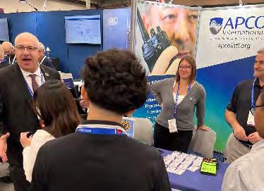
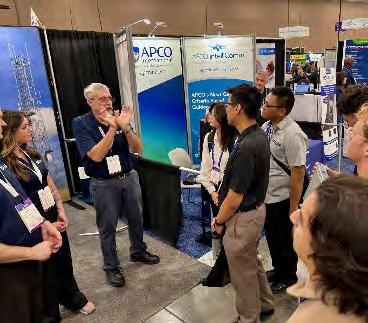
• APCO — stop by the RCA booth for your invitation to the APCO Fellows Dinner and the latest club news.
• IEEE World Forum on Public Safety Technology (WF-PST) — Boulder, CO, September 21–26.
It is an exciting time for RCA. I am proud to be part of an organization with this much history that remains so widely respected across every branch of the wireless arts. Thanks to all of you for making that possible.
And once again, my thanks to David Bart for the tireless work that turns this Proceedings into a reality every year.
ALAN SPINDEL
President The Radio Club of America Inc.
SATURDAY, NOVEMBER 21, 2026
WESTIN
Help Us Honor the Legends, Leaders, and Innovators of Communications
From broadcasting and public safety to wireless, satellite, engineering, and emerging technologies, the Radio Club of America Awards celebrate the people shaping the future of communications. Nominations now open for the 2026 awards program.
For more than a century, the Radio Club of America has recognized the pioneers, visionaries, and leaders whose work has advanced the communications industry and inspired future generations. Now it’s your opportunity to spotlight the individuals making a difference today.
The RCA Awards honor outstanding achievement across a wide range of fields — including wireless innovation, broadcasting, engineering, public safety communications, education, journalism, satellite technology, and industry leadership. Whether it’s a groundbreaking technical achievement, decades of service, transformative leadership, or emerging innovation, every nomination helps recognize the people moving our industry forward.
Do you know someone whose work deserves national recognition? Nominate a colleague, mentor, innovator, or rising leader who has made a meaningful impact on the communications profession. Award recipients are recognized among peers and industry leaders at one of the communications industry’s most respected organizations.
Celebrate achievement. Inspire the next generation. Submit your nominations today.
Learn more about the RCA Award categories and make nominations at www.ly/2026RCAAwards or scan QR code.
2026 RCA Awards
2025 Banquet and Board Meeting
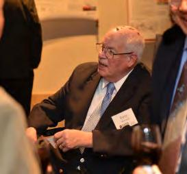
On behalf of the Radio Club of America, the members thank the board of directors for all their efforts, work, and generous service to benefit the club and the general public. Without your commitment, RCA would grind to a halt, depriving everyone of this wonderful organization. Since 1909, RCA’s board members and volunteers have been the lifeblood of its membership, bringing programs, scientific discoveries, technical symposia, tours, demonstrations, awards, and recognitions. There are far too many to name. Each fall, we elect a new board of directors who are approved at the November board meeting and who officially take office on January 1. Congratulations, and thank you all for your generous contributions to RCA!!
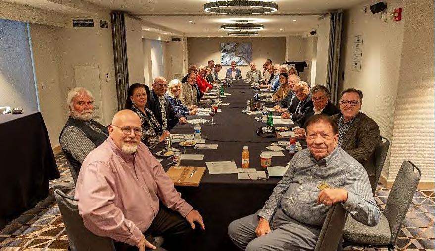
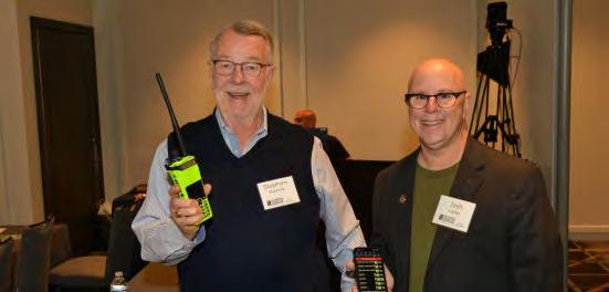
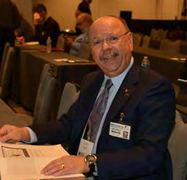
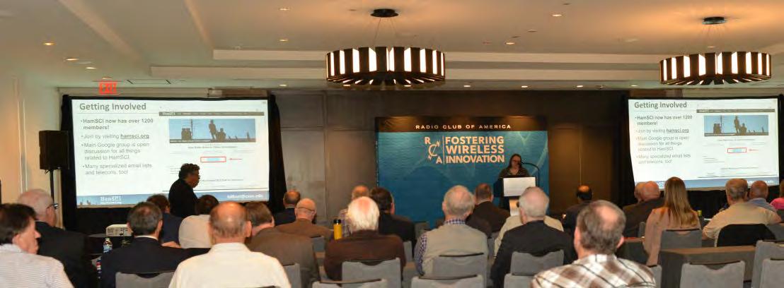
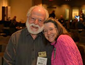
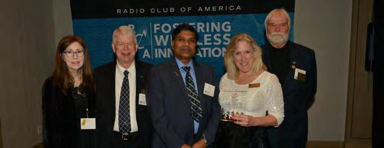
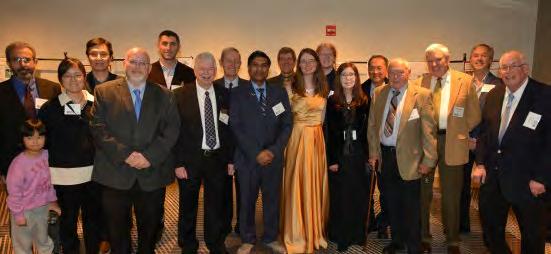
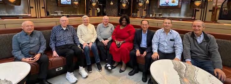
November 2025 Board of Directors Meeting in DC. The 2025 board and the upcoming 2026 board members were all present.
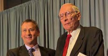
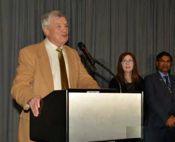
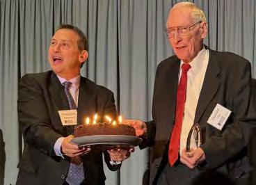
RCA 2025 Technical Symposium coordinators, David Bart and Dr. Nathan Cohen.
Welcoming New Leadership: RCA Announces Board Appointments and 2026 Election Timeline
The Radio Club of America (RCA) is pleased to welcome five distinguished leaders to its Board of Directors: Rachel Jones, Precious Fodor, Louis Fiore, Jack Burbank, and Stephen Jeffries. Each brings a unique perspective and deep expertise across the wireless, broadcasting, and technology sectors, further strengthening RCA’s mission to advance innovation, education, and professional excellence in the communications industry.
Their appointments reflect RCA’s continued commitment to cultivating a dynamic and forward-looking leadership team. As the industry navigates rapid technological evolution— from next-generation wireless networks to the convergence of media and connectivity—these new board members will play a vital role in guiding the organization’s strategic direction and expanding its impact.
Rachel Jones is recognized for her leadership in emerging wireless technologies and cross-industry collaboration. Precious Fodor contributes a strong background in engineering and innovation, with a passion for mentoring the next generation of professionals. Louis Fiore, a longtime advocate for spectrum policy and industry standards, brings decades of experience and insight. Jack Burbank adds depth in broadcasting and media operations, while Stephen
Jeffries offers expertise in organizational leadership and strategic growth. Together, they represent the breadth and diversity of the modern wireless ecosystem.
These newly appointed board members will serve through December 2027, working alongside RCA’s leadership to enhance member engagement, expand educational programming, and strengthen partnerships across the global communications community.
Looking ahead, RCA will hold its next Board of Directors election in 2026. Nominations for this election are due by September 30, 2026. Members interested in participating in the nomination process can access the nomination form, along with the Board of Directors Roles and Responsibilities document, at www.radioclubofamerica.org/Board_Elections. This election provides an important opportunity for members to help shape the future leadership of RCA and ensure continued alignment with the evolving needs of the industry.
Please join us in welcoming Rachel, Precious, Louis, Jack, and Stephen to the RCA Board of Directors. Their leadership and vision will help guide RCA into its next chapter of growth and innovation.
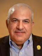
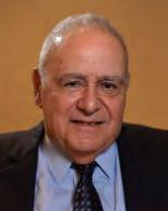
Rachel Jones Precious Fodor
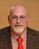
Louis Fiore Jack Burbank
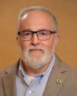
Stephen Jeffries
Well Attended RCA Tours and Fellows Dinner Preceded The November Banquet
Prior to the November 2025 awards banquet and technical symposium, Radio Club of America (RCA) members embarked on several tours and participated in a Fellows Dinner. The day featured an amazing array of experiences and historic locations in a full schedule.
TOURS
An evening lighted monument tour via motor coach included stops at:
• Capitol, White House, Washington Monument, Jefferson Memorial, WWII Memorial
• Lincoln Memorial
• FDR Memorial
• Iwo Jima Memorial
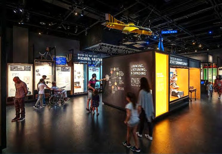
A separate daytime tour included two museums. Their extensive holdings offered many exhibits and places to wander.
• NSA Cryptologic Museum
• Spy Museum
The Spy Museum in Washington DC.
The Spy Museum in Washington DC.
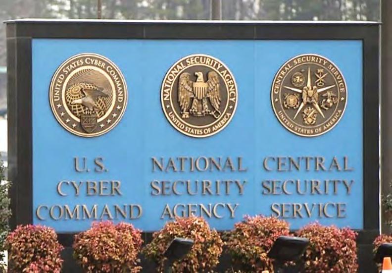
The NSA Museum is located at the home of several US national security agencies.
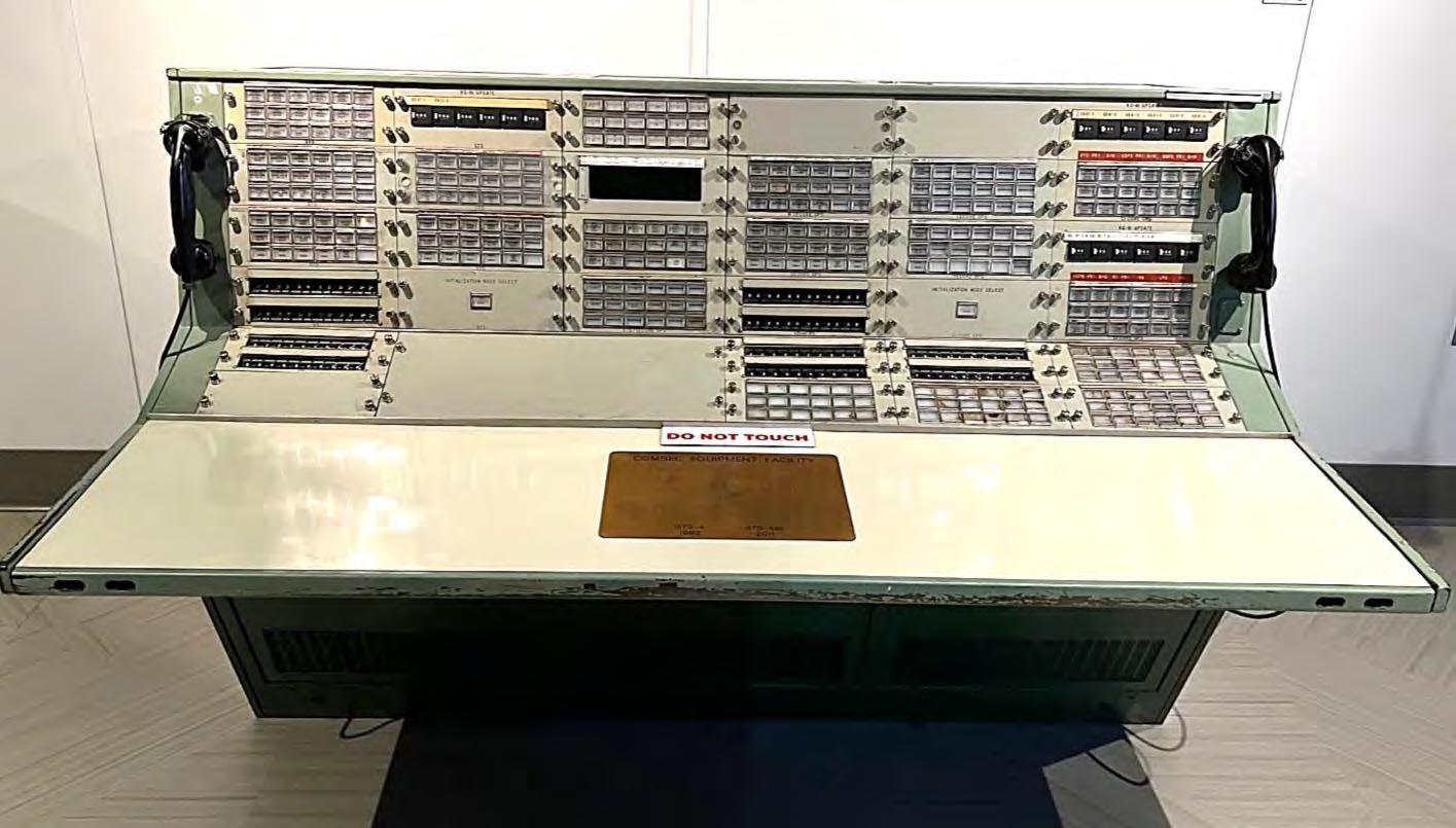
This COMSEC equipment facility controlled secure crypto communications between the Space Shuttle and Houston’s
Space Center from 1982 to 2011.
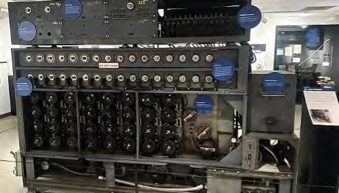
The 1943 U.S. Navy Bombe cryptanalytic machine, at the NSA Museum, the legendary WWII code-breaking machine designed to solve four-rotor Enigmas used by German U-boats.
Johnson
2025 BANQUET RECAP
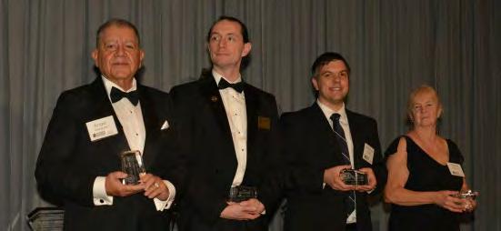
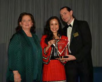
Congratulations To RCA’s 2025 Banquet Participants and Award Recipients
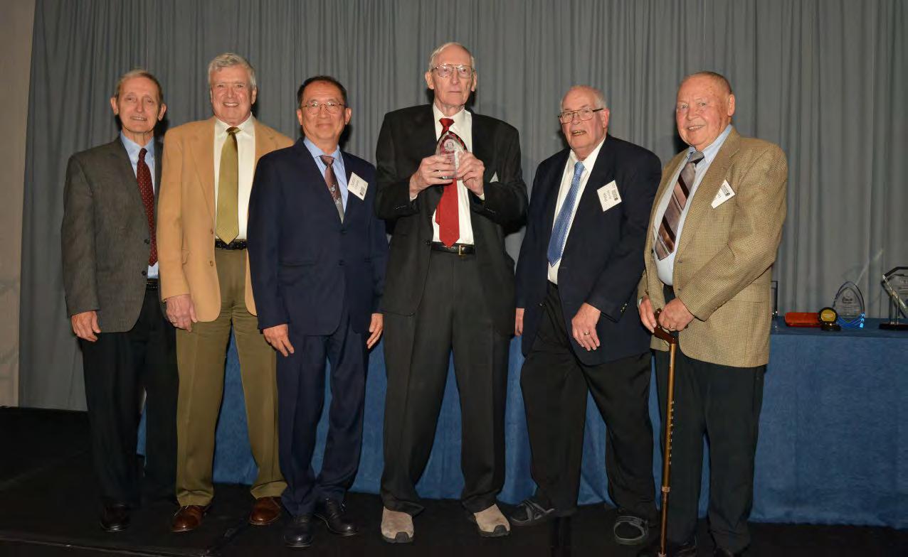
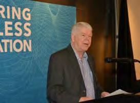
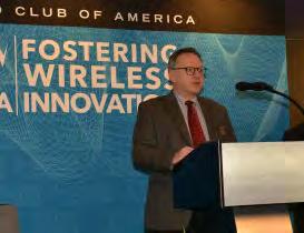
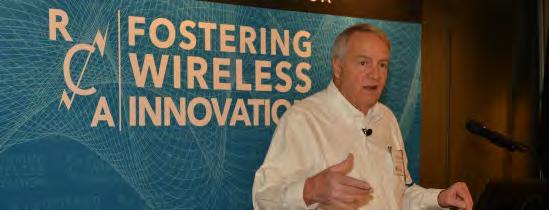
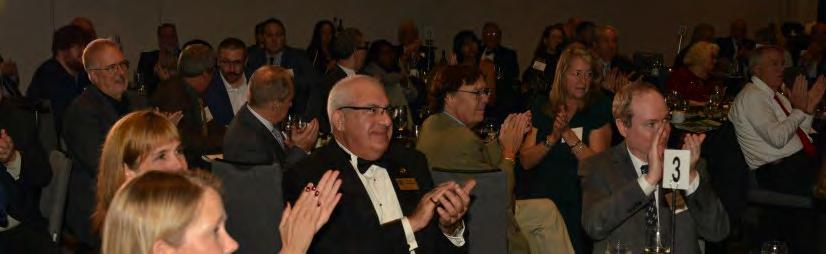
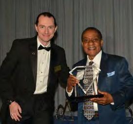
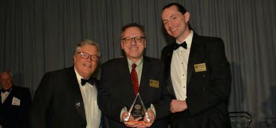
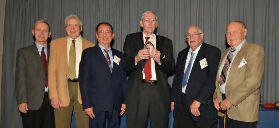
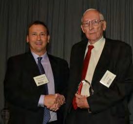
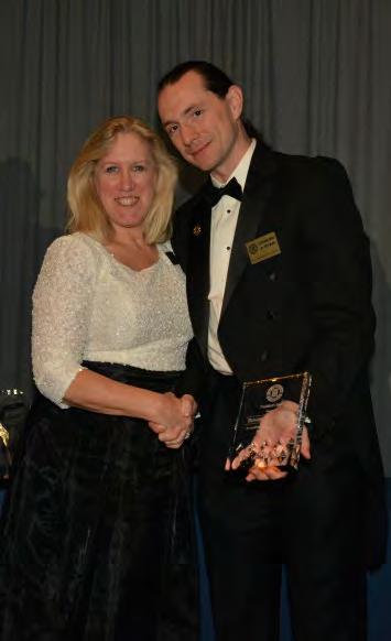
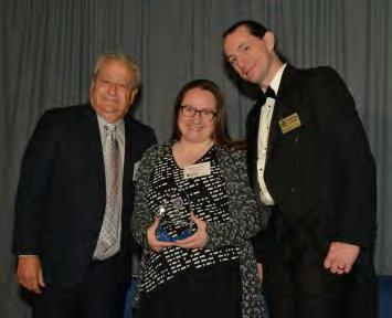
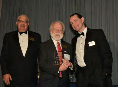
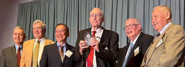
In November 2025, the Radio Club of America (RCA) held its 116th Awards Presentation. We commemorated the anniversary of the many accomplishments of Dr. Robert W. Wilson and Dr. Victor B. Lawrence. Dr. Wilson received the Armstrong Medal, and Dr. Victor B. Lawrence received the Lifetime Achievement Award. Both Drs. Wilson and Lawrence spent significant portions of their careers at Bell Laboratories. The year 2025 marked the centennial of Bell Labs, and RCA was honored to recognize the work of this world-famous laboratory. Congratulations!
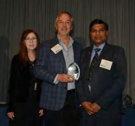
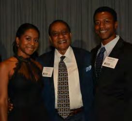
RCA’s 2025 awards banquet recognized the wonderful examples set by scientific and professional leaders for the rest of us through their many achievements and their generous support of students, professionals, academics, and amateurs. This was a busy evening, celebrating 26 people:
• 13 major awards
• 2 RCA leadership service awards
• 2 board service recognitions
• 1 young professional award
• 8 fellows.
Thank you to the banquet planning committee, the awards and fellows committee, and the board for its hard work! In particular, we thank Amy Beckham and the entire Sapphyre team for pulling off a wonderful celebration!
Thank you to all our sponsors and donors, as well as those who purchased items in the donation auction; your generous contributions help enable RCA to continue providing our programs and services.
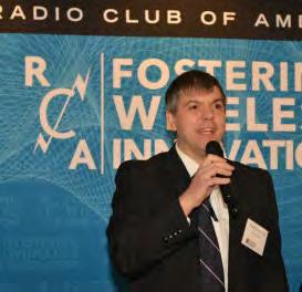
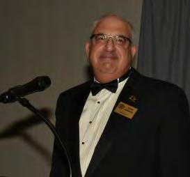
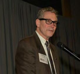
Thank you to all who participated, and we appreciate the wonderful team of presenters: Tim Duffy (Master of Ceremonies), Alan Spindel (RCA President), Ed Ryan (cohost), Dr. Kinuko Masaki (keynote address), and the many people who introduced and presented the awards. The entire ceremony was recorded and can be viewed on RCA’s YouTube channel
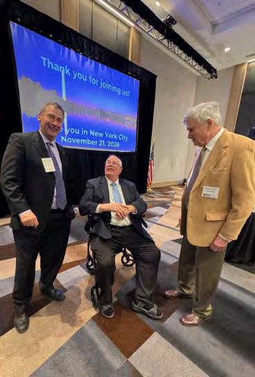
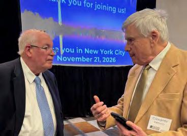
We invite everyone to return for the next award banquet and Technical Symposium, to be held in New York City on November 21, 2026.
RADIO CLUB OF AMERICA’S 2025 AWARDS
Congratulations to all of RCA’s 2025 award recipients and the new class of RCA Fellows who received recognition at the banquet last November. Each recipient deserves recognition for their many contributions to radio and wireless communications. Their work has helped lead the way toward creating and preserving the arts and sciences in wireless communications. Their efforts continue to bring forth new technological advances, benefiting the wireless industry and mankind.
THE ARMSTRONG MEDAL
Dr. Robert Woodrow Wilson
For outstanding achievements and lasting contributions in the arts and sciences of radio and wireless communications.
LIFETIME ACHIEVEMENT AWARD
Dr. Victor B. Lawrence
For significant achievements and a major body of work accomplished over a lifetime that has advanced the art and science of wireless technology.
DR. ARNO PENZIAS AWARD
Dr. Donald C. Cox
For significant contributions to basic research involving RF and related subjects, to inspire future generations of scientific professionals.
DR. ULRICH L ROHDE AWARD
Dr. Peter Wolniansky
For significant contributions to innovation in applied radio science and engineering in the wireless industry, to inspire future generations of wireless professionals.
PRESIDENT’S AWARD
Margaret J. Lyons, PE, RF/Communications Engineer
For unselfish dedication to the work of the Radio Club of America.
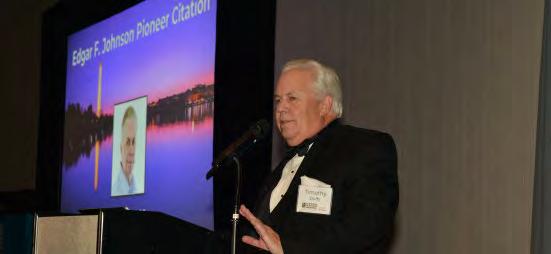
EDGAR F. JOHNSON PIONEER CITATION
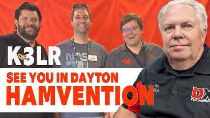
Timothy Duffy – K3LR
For noteworthy innovations and contributions to the success of the Radio Club of America or to the radio industry.
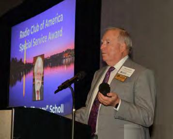
SPECIAL SERVICE AWARD
Chester B. Scholl, Jr.
For RCA members who have performed significant work to advance the goals and objectives of the Radio Club of America.
VIVIAN CARR AWARD
Dr. Kinuko Masaki
Recognizing outstanding women for their achievements in the wireless industry.
JAY KITCHEN LEADERSHIP AWARD
David Bart
For leadership that embodies energetic advocacy, cooperation, avid interest, respect for all, and humor, and who has achieved a high level of success leading a wireless association, government agency, or commercial enterprise.
EXCELLENCE IN SALES AND MARKETING AWARD
Larry Weber
For “Esprit de Corps” in sales, marketing, and promotion in the wireless industry, and saluting dedication to the industry, and a professional and ethical approach to business relationships and integrity when representing the industry and working for the betterment of the Radio Club of America.
JACK POPPELE AWARD
Robert “Bob” Orban
For important and long-term contributions to the field of radio broadcasting.
BARRY GOLDWATER AMATEUR RADIO AWARD
Julio Ripoll, WD4R
Recognizing unique contributions to the field of amateur radio.
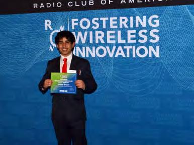
CAROLE PERRY YOUNG PROFESSIONAL AWARD
Dr. Kristina Collins, KD8OXT
Honoring a young professional who was part of the RCA Youth Activities Program in their formative years and who has gone on to a career in wireless science.
US
NAVY CAPTAIN GEORGE MCGINNIS MEMORIAL AWARD
CTRCS Roy S. Lamberton
For service and dedication to the advancement and preservation of U.S. Naval Cryptology, as nominated by the U.S. Naval Cryptologic Veterans Association (NCVA).
RCA Inducts 2025 Class of Fellows
Each year, RCA elevates a small group of members to Fellow status whose contributions are deemed outstanding to the art and science of radio communications or to the Radio Club of America. Elevation to Fellow status is approved by the board of directors after nomination and review. This occurs when they have been a member of RCA for at least five years and have made substantial contributions to the science and/or art of radio broadcasting, or to RCA itself.
The RCA board of directors selected the following members to be elevated to Fellow status in 2025. Roman Kaluta accepted on behalf of the 2025 class of RCA Fellows, delivering his comments at the awards ceremony. Congratulations to all for their many contributions!!
RADIO CLUB OF AMERICA’S 2025 FELLOWS
Brian Daly
AT&T Assistant Vice President and AT&T Fellow.
Felicia Kreuzer
Antique Wireless Association Board of Directors and Assistant Museum Curator.
Stephen Martini
Past-President, Association of Public-Safety Communications Officials (APCO).
Edward Ryan Tutunjian & Bitetto, P.C.; RCA Vice President / Co-counsel.
Dr. Nathaniel Frissell
Associate Professor of Physics and Engineering at The University of Scranton.
Monte Simpson
Public Safety Communications Leader, 47-year career.
Roman Kaluta
Director of Business Development –Public Safety Liaison and Customer Advocate for JPS Interoperability Solutions.
Angel Vazquez
Head of Telescope Operations and Puerto Rico Coordination Zone Spectrum Manager, Arecibo Observatory.
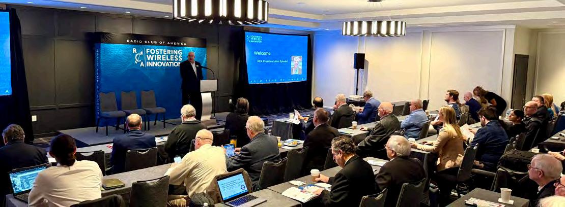
RCA’s 2025 Technical Symposium Was a Huge Success!
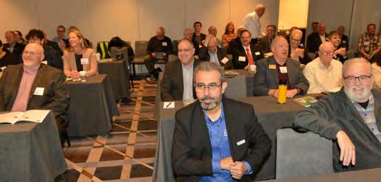
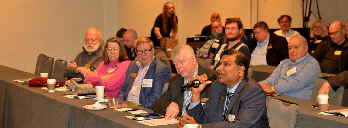
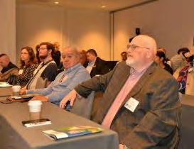
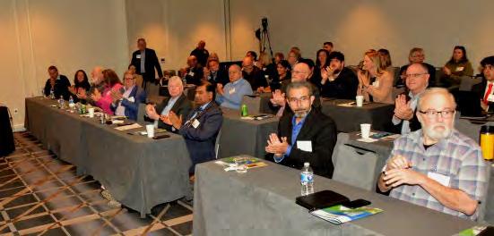
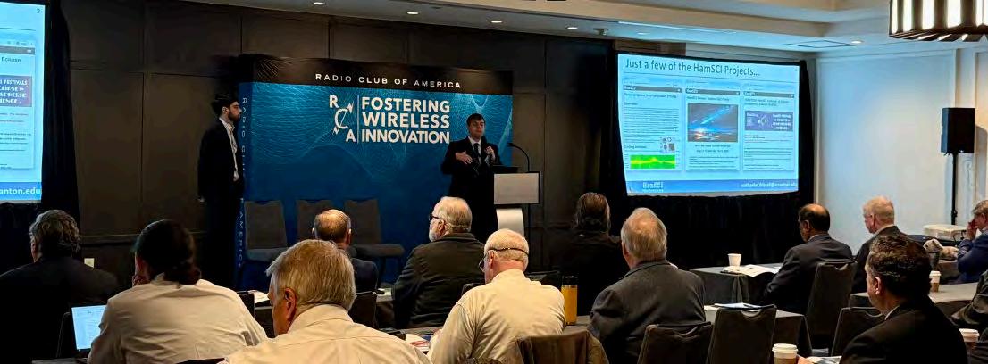
The Technical Symposium held in Washington, D. C. on November 22, 2025, was a spectacular success. RCA’s annual opportunity to learn about innovative wireless technology had significant participation. The all-day symposium is indeed one of the wireless industry’s premier events.
TECHNICAL SYMPOSIUM
RCA presented 12 sessions, 1 panel, and hosted 12 poster presentations. A bevy of research and industry leaders. covered GPS security and countermeasures, propagation, ionospheric disturbances, interoperability, McMurdo Station operations, communication history and outlook, disaster relief and Cubesats, broadcasting, the National Hurricane Center, Loran, beam curving, and BLAST. The panel discussed the outlook for public safety and the use of push-to-talk over cellular. Student poster presentations were warmly welcomed during the reception, giving students the opportunity to meet radio science and industry notables. Congratulations to everyone for making this a stimulating day of technology education and discussion!
The presentation slides and a video of the presentations are available on the RCA website, and presentations can be seen on the RCA YouTube channel.
Thank you to Dr. Nathan “Chip” Cohen and David Bart (Technical Symposium Co-chairs), and the Technical Symposium Committee, including Dr. Ajay Poddar, Dr. Jim Breakall, Dr. Julio Urbino, and Dr. Kit August, for organizing this terrific 2025 event. Thank you to our many sponsors. In particular, we thank our IEEE partners at the Antennas and Propagation Society, North Jersey Section, and Eta Kappa Nu (HKN) for their generous support of the poster presenters.
THANK YOU TO OUR 2025 TECHNICAL SYMPOSIUM PRESENTERS
GPS Security and Countermeasures: PNT in GPSDegraded Environments — Jack L. Burbank
The Lion In the (Propagation) Path — Kristina Collins
Large Scale Traveling Ionospheric Disturbances with the WSPR/PSK Reporter/RBN Data — Nathaniel Frissel and Diego Sanchez
FirstNet Fusion: The Evolution of Interoperability — Jennifer Harder
Frozen Frequencies: Life and Radio Work at McMurdo Station — Rachel Jones
Evolution of Technology for Transformative Communication for Humanity — Victor Lawrence
Eyes In the Sky: Advancing Disaster Relief Coordination with Convolutional Neural Networks and Real-Time CubeSat Data — Abigail Merchant
War Stories from the Front Line of Broadcasting — Mike Pappas
Amateur Radio at the National Hurricane Center — Julio Ripoll
Loran, or “There and Back Again” — Charles Schue
Curving Beams: A New Generation of Wireless Capabilities — Caroline Spindel
Blast AKA MIMO — Peter Wasily Wolniansky
PUBLIC SAFETY PANEL: Current Developments and an Outlook for Public Safety and the Use of Push-to-talk Over Cellular — Roman Kaluta (moderator), Thomas Kelly, Harlin McEwen, Josh Lober
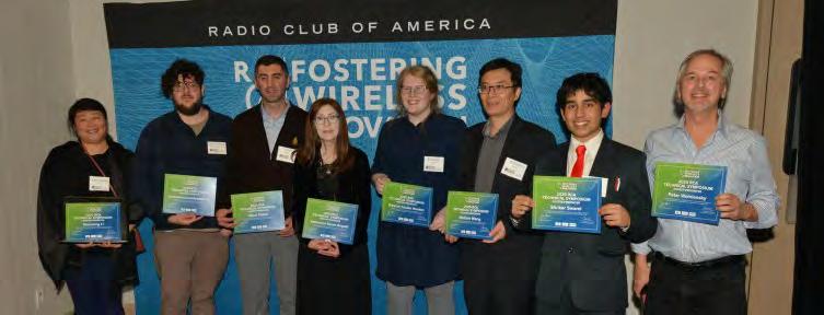
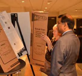
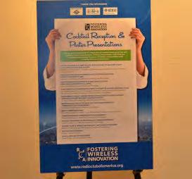
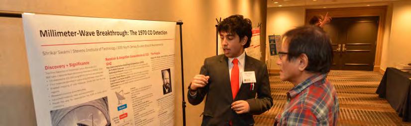
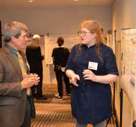
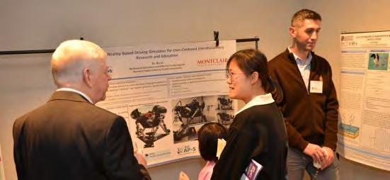
RCA’s 2025 Technical Symposium featured 12 poster presentations by advanced college and PhD students, and a few professional contributions, including one on RCA’s impact on changing paradigms in communications. The students were positioned around the reception area wall, giving them an excellent opportunity to meet RCA luminaries. They were very well received. The posters fostered great discussion and welcome participation from attendees. Thank you to everyone who brought these terrific materials to RCA!!
THANK YOU TO OUR 2025 TECHNICAL SYMPOSIUM POSTER PRESENTATIONS
Anti-Blackness in Cyber Spaces: Applications of Machine Vision in Studies of Race and Racism — Xuemeng Li, PhD (Hunter College) and Demetrios Lambropoulos (Rutgers University, New-Brunswick)
Modeling Cellular Networks: Base Station Clustering From Open-Source Data — Demetrios Lambropoulos (Rutgers University, New Brunswick)
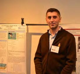
Electromagnetic Absorption and Cancellation: Principles and Practical Limits — Yosuf Ozkan (New Jersey Institute of Technology)
A Multimodal Collaborative Robot System For HumanCentered Tasks — Dr. Weitian Wang (School of Computing at Montclair State University and Director of Montclair Collaborative Robotics and Smart Systems Laboratory)
An Extended Reality-Based Driving Simulator For UserCentered Interdisciplinary Research and Education — Dr. Rui Li (School of Computing, Montclair State University)
Behind Evolution of Technology For Transformative Communication For Humanity — Chris Lawrence (Stevens Institute of Technology)
MIMO Communications – Peter Wolniansky, et. al. (in addition to AT&T Labs, also Affiliated with Rutgers University for IEEE)
Transformative Communication For Humanity — Nathan Lawrence, et. al. (Stevens Institute of Technology)
History: Discovery of Interstellar Carbon Monoxide — Shrikar Swami, et. al. (Stevens Institute of Technology)
History Karl G Jansky, Am Skellett, And Radio Astronomy — Katherine Grace August, PhD (Stevens Institute of Technology)
Setting the Standard — Eleanor Louise Heaton
RCA: A Century of Changing Paradigms — David Bart
Preparations are already underway for the 2026 Technical Symposium in Washington, DC. A call for abstracts for this year’s Technical Symposium, along with an invitation to prospective presenters to submit their ideas, is available on the RCA website.
We hope to see you all live in 2026!
Plans For The RCA 2026 Technical Symposium
The 2026 Technical Symposium will be in New York City on Saturday, November 21. Topics and speakers are still being organized. We are looking for presenters in any of the areas of wireless technology, including antennas, broadband, broadcast, cellular, land mobile radio, military, satellite, or other wireless-related technologies. We will again welcome poster presentations. RCA especially likes to feature ‘early work’ and offers researchers and companies an opportunity to gain feedback on the technologies they are developing.
We are calling for abstracts from potential presenters. Please contact the 2026 Co-chairs, Dr. Nathan “Chip” Cohen and David Bart, if you have suggestions or ideas. Please email info@radioclubofamerica.org or visit https:// radioclubofamerica.formstack.com/forms/technical_symposium_submission.
Also, make your reservations early. The hotel block sells out quickly. Information is on the RCA Website.
2025 Technical Symposium Photos
2025 Technical Symposium Photos
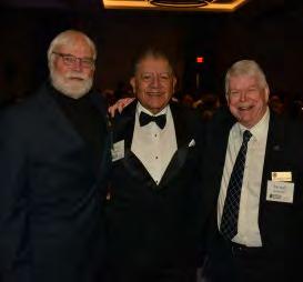
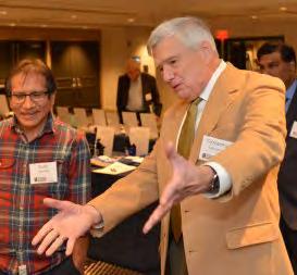
2025 Awards & Banquet Photos
2025 Poster Presentation Photos
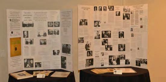
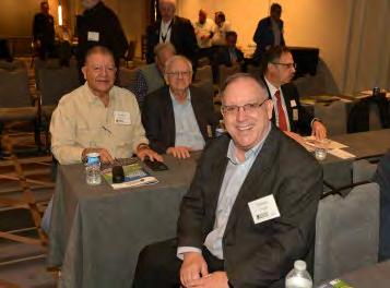
2025 Board Social Dinner
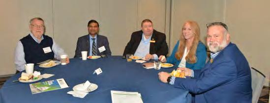
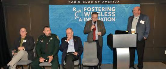
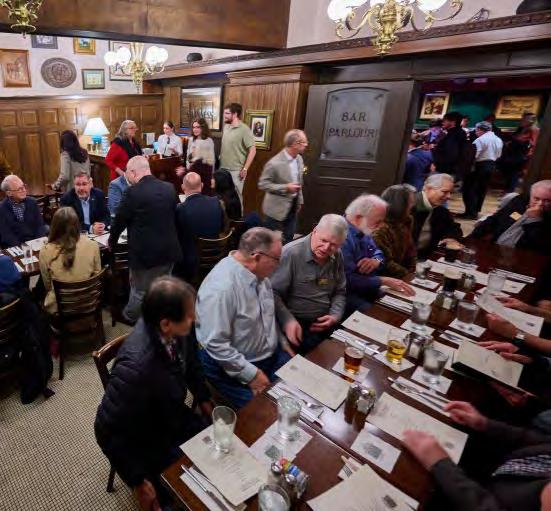
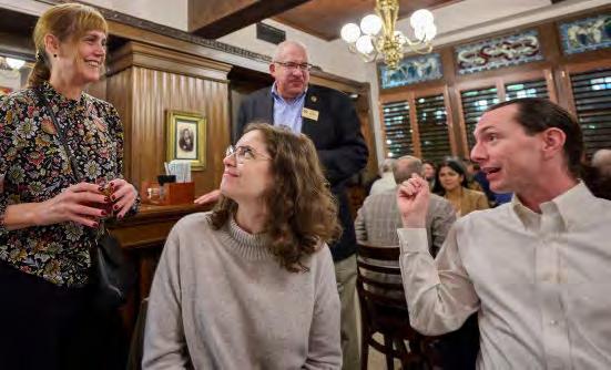
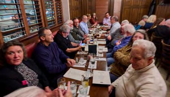
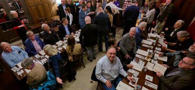
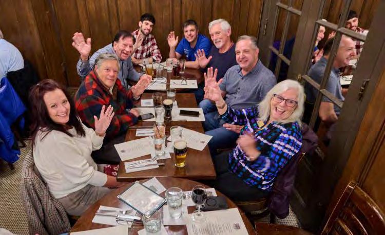
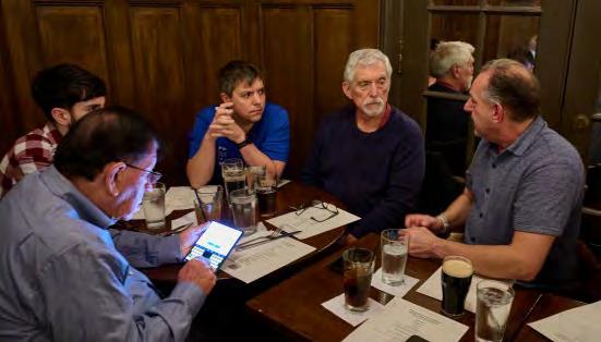
RCA held a reception and dinner at The Dubliner, a legendary Irish pub near the hotel, across from the Union Station complex. The dinner was extremely well attended, with about 60 people tightly packed into the reserved room. Spirits were high as the group shared stories and a rousing good time.
2025 Fellows Dinner
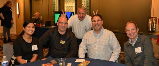
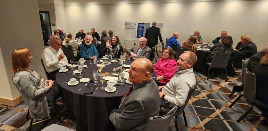
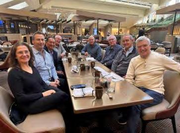
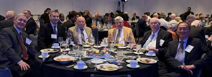
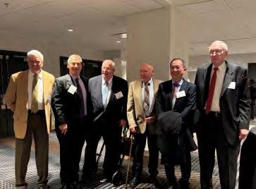
RCA held a special Fellows Dinner at the hotel. We are making this a new regular feature of the banquet weekend. The dinner was well attended, with about 35 people sharing stories, networking in a reunion type atmosphere.
RCA’S Video Interview Series is on Youtube
Radio Club of America (RCA) president emeritus John Facella continues to host RCA’s online interview series. Many of the sessions are recorded and are available on RCA’s YouTube Channel.
These programs provide meaningful and interesting discussions about experiences, viewpoints, and developments in wireless technology. They provide a valuable historical resource. Each interview runs approximately 1 hour. Guests include a wide range of notable figures in wireless, discussing their careers, passions for radio, views on industry trends, and outlooks for technology. If you missed any of these interviews, they are available at https://www.youtube.com/ playlist?list=PLx5vFACfP6FkoU02HpbqMNFBziAAiqqCB
HISTORY SHARED AND PRESERVED
The RCA Interview Series has hosted more than 50 people to date. It provides a valuable record of leaders participating in many aspects of RF. RCA’s Interview Series is one of the larger oral/video history collections
comprising interviews of electrical engineers and related technologists dealing with wireless technology. RCA’s YouTube Channel also includes presentations from its Technical Symposiums, available at https://www.youtube. com/@radioclubofamerica7981/playlists.
Thank you to everyone participating in RCA’s Interview Series and other programs. Together, you have made history, shared it, and preserved it for posterity.
THANK YOU 2025 SPONSORS
The Radio Club of America Board of Directors and its members would like to thank the generous 2025 sponsors. Be sure to tell them that you saw their company mentioned in the Radio Club of America Awards Program.
2025 AWARDS PROGRAM SPONSORS
TITANIUM
Thanks to our sleek new RCA web site, opportunities to host innovative virtual programs and more new ways to connect with RCA members, being an RCA sponsor is a better-than-ever investment in the future.
Contact Karen Clark, Sponsor Committee Chair at kjclark33@comcast.net for more information!
Our organization grows and encourages innovation because of your support. With your support, our organization continues to grow and encourage innovation.
Thank you!
E-mail: andrew.maxymillian@bluewing.com
Andy Maxymillian, PMP
Save the Date!
2026 TECHNICAL SYMPOSIUM AND 117TH BANQUET & AWARDS PRESENTATION
SATURDAY, NOVEMBER 21 | NEW YORK CITY
Registration for the 2026 Technical Symposium and Banquet will open after Labor Day.
REASONS TO ATTEND THE RCA BANQUET AND TECHNICAL SYMPOSIUM
Front-row access to what’s next in wireless
Gain insider perspective on emerging technologies—6G, private networks, satellite integration, and beyond—directly from the experts shaping them.
High-impact, executive-level content
Sessions are curated for substance over noise, delivering practical insights you can immediately apply to strategy, innovation, and operations.
Unmatched networking with industry leaders
Connect with senior executives, engineers, policymakers, and innovators across the wireless and broadcast ecosystem in a highly engaged setting.
Cross-industry perspective you won’t find elsewhere
Explore how adjacent sectors—telecom, broadcasting, defense, and academia—are converging to drive the future of connectivity.
Visibility for you and your organization
Whether attending, speaking, or sponsoring, the symposium offers a platform to elevate your brand and thought leadership within a prestigious community.
Be part of RCA’s legacy of innovation
Engage with one of the industry’s most respected organizations and contribute to conversations that shape the next generation of wireless advancements.
Inspiration that goes beyond the evening
Hear powerful stories of innovation, leadership, and impact that will energize your thinking and perspective long after the event ends.
Prime New York City experience
Enjoy an unforgettable evening in NYC—combining worldclass hospitality, iconic ambiance, and the energy only the city can offer.
SPACE-BASED RF POWER TO GROUND (PTG): THE DREAM AND THE PATH
By Dr. Nathan Cohen
INTRODUCTION
Unlike other species, people are poorly designed for living without controlling, utilizing, and directing the environment of the Earth. Left to our own biology, there are inherent limits on what we can achieve. Beyond that, we need the enablement of technology and technology needs power. Power is the currency by which we shape ourselves, produce harmony with the world, and enhance the human condition. The problem, then, is not the creation of energy, but access to it.
All usable energy on Earth is, in one form or another, solar in origin. Fossil fuels are stored sunlight. Wind, water, and weather are solar-driven. Geothermal, nuclear, and tidal energy are echoes, remnants of planetary accretion afforded by being captives of the Sun. Even biological systems are powered by the same radiative flux from our star. The Sun is not simply a contributor to the terrestrial energy budget—it is the source of power.
On the surface of the Earth, direct solar energy is intermittent by nature. Day and night, weather, and atmosphere break what is otherwise a continuous radiative field into fragments. The result is not a lack of energy, but a lack of continuity. Terrestrial systems compensate with storage, over-build, and distribution, adding complexity to recover what is naturally steady at the source. On the surface of the Earth, solar power collection is limited by the vagaries of being of the Earth.
In space, this constraint disappears. The solar flux is continuous, stable, and always available, at 1361 watts / m^2. In space, the limitation is no longer sourcing the power: It is defining the system and delivering it back to Earth. Yet the delivery of this is both a promise and a problem. How do we tap into the solar power of space and bring it to the Earth? How do we bring ‘power to ground’ (PTG)?
PTG has been proposed for decades. The validity of its physics has never been in question. The Sun provides the energy. Electromagnetic theory provides the means of transmission. And yet, systems have remained unrealized— not because they are impossible, but because they have been problematic to execute and, possibly, incompletely conceived.
In this two-part piece, the power-to-ground problem is detailed and summarized, and in doing so, a new approach is presented, based on surface area as the defining parameter for power acquisition and system success. This first part establishes the governing physics and system definition; quantitative implementations and engineering realizations are treated in Part 2. Wireless RF plays a key role in all future PTG and with its success, is likely to become a dominant field of RF endeavor. Here we consider those prospects and the trials that deter the success of PTG.
THE WIRELESS PIPE AND THE GOLDILOCKS DILEMMA
The case for PTG is straightforward: collect solar radiance, convert it to watts, transmit it to the ground, and convert it to electricity. The power is beamed electromagnetically from a satellite. That beam acts as a “wireless pipe” with matched ends. The beamwidth at the satellite sets the spot size on the ground through diffraction, and the ground power-receiver system is scaled to match that area and collect the power.
This requires beam-to-spot matching. If the distance—the length of the pipe—increases, the spot size increases accordingly, and the receiver system must scale to match it. When there is such matching, space introduces little attenuation, and the wireless pipe is effectively independent of distance in delivered power.
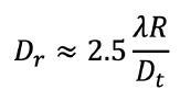
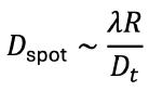
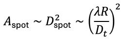
A simple mathematical analysis shows the basics. For a distance R, a wavelength λ , a transmit aperture diameter D t, and a ground power receive diameter Dr, approximately 95% of the power is received when (for an FWHM-defined Gaussian beam):
The pipe analogy is therefore appropriate: in a lossless system, the delivered power equals the collected power, and the system is governed by the ratios of the relevant diameters at both ends of the pipe. But complexities and complications remain.
Choosing the spectrum for the pipe presents a Goldilocks dilemma: finding a transmission regime that is “just right.”
A laser, for example, while highly collimated, does not escape diffraction. Its spot size still grows with distance according λ R/D t. Because the wavelength is small, the beam can be made extremely narrow, but this creates a different constraint: the required pointing accuracy becomes correspondingly extreme. For practical apertures, the beam footprint on the ground can also be very small, requiring extremely precise pointing control to avoid missing the receiver system or depositing energy off-target. In addition, laser systems are typically conversion-intensive and require significant thermal management so that the mean time between failures is not unacceptably short.
Visible-light transmission, apart from lasers, offers no clear advantage. Incoherent beams do not remain well-collimated over long distances, requiring very large optical systems to control the ground spot size under diffraction. Visible light trades the pointing constraints of lasers for aperture and optical complexity, while also introducing atmospheric scattering and sky illumination concerns.
Infrared systems are constrained, poor choices because atmospheric absorption results in severe attenuation of IR power to the ground.
RF occupies the most useful middle ground. Its wavelength is long enough to relax pointing accuracy demands and avoid the severe off-target risk of an optical beam, yet short enough to permit directed transmission with practical apertures and controlled spot sizes at the ground. It is therefore a Goldilocks regime: not so narrow as to be
operationally critical, and not so broad as to become ineffective.
RF transmission benefits from well-established atmospheric transparency windows. In particular, the microwave window, long recognized in SETI as a region of minimal cosmic and atmospheric noise, also defines a regime of minimal atmospheric absorption for terrestrial propagation. This window spans roughly from about 1 GHz to 35 GHz, bounded by the principal absorption lines of water vapor and oxygen. Within this window, attenuation through the atmosphere is low under most conditions, allowing RF power beams to propagate to the ground with relatively little loss, even in the presence of clouds or moderate weather, in contrast to optical and infrared systems. The result is a transmission channel that is not only reasonably efficient, but operationally reliable and largely insensitive to atmospheric variability.
RF beams have an advantage in that they can distribute power over large areas at low intensity, providing inherent safety margins and graceful degradation under pointing errors. RF transmission avoids the unrealized optics of visible-light systems and the worst atmospheric penalties of many infrared bands, while remaining compatible with large-area receiving structures on the ground—functionally equivalent to large-scale solar farms. RF transmission therefore emerges as the regime that simultaneously satisfies the physical, atmospheric, and system-level constraints of practical PTG.
Power from Microwave—The 19th Century Pioneer
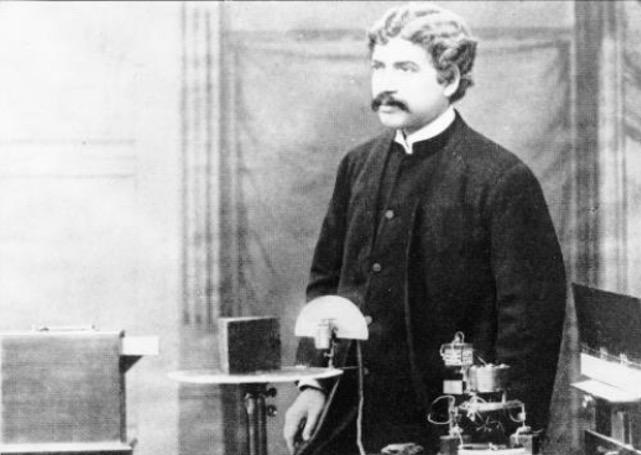
Jagadish Chandra Bose (1858–1937) was working astonishingly far ahead of his time. In 1890s Calcutta, he didn’t just explore radio—he pushed it into the millimeter-wave regime, building an entire experimental system from scratch: spark transmitters operating around 60 GHz, waveguides to direct the energy, dielectric lenses to focus it, and the first horn antennas to launch controlled beams.
With this setup, he demonstrated that electromagnetic waves at very short wavelengths could be manipulated like light—focused, polarized, and steered with precision—laying conceptual groundwork that wouldn’t be fully appreciated until decades later in telecommunications and radio astronomy.
His experiments culminated in a striking demonstration in 1895: he transmitted energy across 23 meters, through walls, triggering a bell and igniting gunpowder(!) at the receiving end. Yet despite this breakthrough, the work stopped short of practical application. The transmitted power was enough to trigger events but not sustain usable energy transfer, and the components
of the era were too crude for efficient systems at such high frequencies. As a result, industry turned toward longer, more manageable wavelengths, leaving Bose’s millimeter-wave innovations as a brilliant but premature glimpse of the future—proof that directed highfrequency energy was possible, even if the technology of his time couldn’t yet make it useful.
THE PIECES OF THE PIPE
The wireless pipe is not a single device, but a system described by function components that must operate together to enable power delivery from space to ground. Each component plays a distinct role. At a minimum, a practical PTG system consists of the following components:
1.
Solar Collector (Space Satellite)
The solar collector captures incident solar radiance in space and converts it to usable electrical power. This is typically implemented as photovoltaic arrays or other high-efficiency solar energy conversion systems. In this regime, the defining parameter is not simply conversion efficiency, but collecting area, since the available power scales directly with the size of the surface exposed to the Sun. In other words, the power gathered goes as the effective diameter squared.
2.
Power Conditioning and Conversion (Space Satellite)
The collected electrical power must be conditioned, regulated, and converted into a form suitable for transmission. This includes DC power management, voltage transformation, and conversion into RF power via a transmitter and amplifiers. While critical, this stage does not
define the system’s capability; rather, it preserves the power gathered by the collector and prepares it for transmission in another form, that is RF. Losses accumulate additively so that a sizeable but not total amount of the collected power gets converted, as an ‘engine’ into RF.
3.
Transmit Antenna (Space Satellite)
The transmit antenna defines the beam. It converts RF power into a directed electromagnetic field and establishes the beamwidth that determines the ground spot size. Its diameter and phase control capability are central to system performance, governing diffraction and therefore the geometric expansion of the beam. In this sense, the transmitter is not defined by its power alone, but by its aperture, which sets the fundamental relationship between wavelength, distance, and spot size. The spot size, as previously discussed scales inversely as the antenna’s diameter.
4. Beam Control and Pointing System
A control system is required to maintain alignment between the transmit beam and the ground receiver. This includes beam steering, phase control (for phased arrays), and tracking systems to ensure that the transmitted power
Power from Orbit—The Systems Engineer Source
Peter Glaser(1923-2014) is most closely associated with the invention of the solar power satellite, but his technical contributions extended well beyond that single concept into a broader portfolio of aerospace and energy-system engineering. Trained as an engineer and working at Arthur D. Little, Glaser approached problems at the systems level—integrating materials science, thermal physics, RF, and space systems design into coherent architectures.
In addition to his landmark 1973 patent on space-based solar power, Glaser was also an inventor on earlier work such as thermal conductivity measurement systems for cryogenic and space environments. These devices addressed a fundamental engineering constraint in spacecraft design: accurately characterizing heat transfer in insulation and structural materials under extreme temperature gradients. This work reflects a recurring theme in his career—developing enabling measurement and control techniques for high-performance systems operating outside terrestrial conditions.
Across his career, Glaser contributed to a wide range of advanced concepts, including solar and arc imaging furnaces, photovoltaic energy conversion systems, lunar surface and extravehicular (EVA) technologies, and wireless power transmission for high-altitude platforms. His studies also encompassed power relay satellites, remote sensing architectures, and contamination and dust mitigation systems for space hardware—each addressing a specific bottleneck in the realization of large-scale space infrastructure.
remains properly directed over long distances. Although RF systems relax pointing requirements relative to optical systems, alignment remains essential, as it determines whether the transmitted energy remains within the bounds of the receiving aperture.
5. Free-Space Propagation Channel
The transmission path through space and atmosphere forms the body of the pipe. In RF systems, this spectral channel introduces minimal attenuation within the microwave window but imposes geometric spreading governed by diffraction. What appears as loss is not absorption, but expansion of the beam, and this expansion diameter must be matched at the receiver for effective power capture.
6. Ground Receiving Antenna (Rectenna)
The ground receiver is implemented as a rectifying antenna, or ’rectenna’—a large-area array of antenna elements coupled to rectifying circuits that convert incident RF power directly into DC electrical power. The rectenna defines the effective collection aperture and must be scaled to match the transmitted beam spot for efficient power capture. In this sense, the receiver is the complement of the transmitter, and its area is as critical to system performance as the transmit aperture.
7. Power Collection, Storage and Grid Interface (Ground Segment)
The DC power produced by the rectenna must be aggregated, conditioned, and converted into gridcompatible electrical power. This includes inversion to AC, voltage regulation, and integration into existing electrical infrastructure. Storage is also essential to average out the system against loss of PTG coverage. This stage completes the pipe, transforming received energy into usable electrical power at scale.
8. Some System Limiting Considerations
While each component is necessary, system performance is governed by a small number of dominant constraints.
Surface area defines the system. The transmit aperture sets the beam through diffraction, and the receive aperture sets what is captured, with delivered power following directly from their matching. Diffraction imposes the geometry, fixing the ground spot size as λ R/D t and requiring that expansion to be matched rather than overcome. Efficiency multiplies across the chain, with no single conversion stage dominating but all contributing to the total. Pointing defines stability, as RF systems tolerate misalignment but still require the beam to remain within the receiving aperture. The atmosphere selects the band, with the microwave window providing low-loss transmission and regions outside it rapidly degrading performance. Scalability follows area, as increasing system capacity requires expanding apertures rather than increasing intensity. The wireless pipe is therefore not limited by transmission, but by geometry, with surface area governing both the collection and delivery of power.
THE HISTORICAL PATH: OPENED, NOT CLOSED
The historical path to power-to-ground has been builtup over decades, and includes the most grand-in-scale engineering proposals ever devised by man. But grandeur itself has not prevented PTG. The parts are known, its physics is understood, and the components of the system have been individually demonstrated. What has not occurred is closure: a complete working and successful system. The system has not been assembled in a way that completes the chain from collection to delivery, and the result has been a sequence of implementations in which the pieces exist but do not fully resolve into a working whole, or at least one that is viable compared to extant solar farms. In other words, the engineering of the system has not closed in on a workable design.
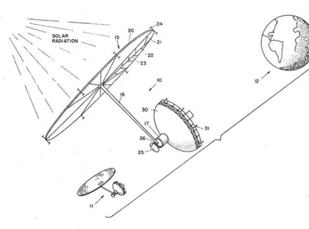
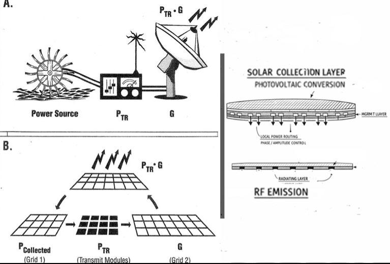
The modern formulation of PTG originates with Peter Glaser (1973), who proposed a space-based solar power satellite transmitting energy to Earth via microwaves. See the adjacent Figure 1. The system consisted of a photovoltaic array in geostationary orbit, converting solar radiance into electrical power, feeding a microwave transmitter with separate dish antenna, operating in the centimeter-wave band, and illuminating a ground-based rectifying antenna array. The architecture was explicit: collection, conversion, transmission, and reception. The principal elements of the system were identified at the outset.
1: Artist view of a Glaser PTG satellite. Note antenna totally distinct from solar panels. This system is engineered for predominantly separate and sequential components. High power aggregation to the antenna poses a fierce burden on componentry and is a design weakness of the system. Author credit.
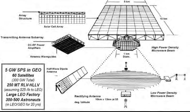
The Solar Power Satellite studies conducted in the 1970s by NASA and the U.S. Department of Energy expanded this concept into detailed system designs (see Figure 2 for example of a gargantuan PTG concept). These studies examined platforms in geostationary orbit with solar arrays extending several kilometers, producing gigawatt-level electrical power. Transmission was to be accomplished through immense phased-array microwave antennas, typically hundreds of meters to over a kilometer in diameter, operating near 2.45 GHz or 5.8 GHz. The transmitted beam
FIGURE
was directed toward groundbased rectenna fields spanning tens of square kilometers, composed of distributed antenna elements coupled to rectifying circuits. These studies included full link analyses, beam control considerations, and efficiency estimates, providing a complete system description at the conceptual level. That these megaprojects rivalled and exceeded the building of the pyramids for shear effort is a clear indication of failure to engineer a system with a ‘closed’ design.
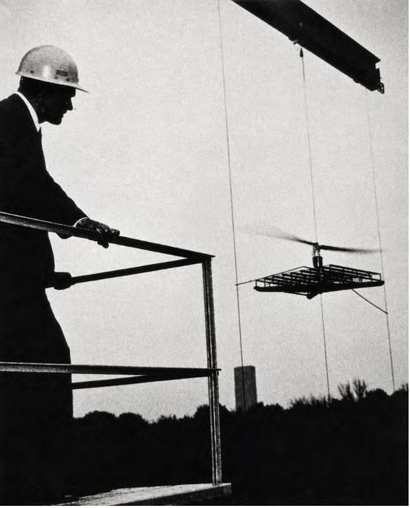
At the ground, reality proved in better proportions: the rectenna was one of the earliest components to be demonstrated experimentally. Work led by William C. Brown (1969) and Figure 3 in the late 1960s and early 1970s established the feasibility of converting microwave energy directly into DC electrical power. These systems used arrays of dipole antennas feeding rectifying diodes, achieving high conversion efficiencies under controlled conditions. The design was modular, consisting of large numbers of lowpower elements combined over area, and could be extended
FIGURE 2: This massive proposed PTG was designed to be kilometers in size and require a city in space to build and service it, a well meaning but generationally intensive pyramid in the sky. NASA credit.
FIGURE 3: William Marks dons a hardhat as his rectenna(bottom structure) powers a helicopter by microwaves. In PTG the rectenna replaces or doubles as the solar farm. Raytheon credit.
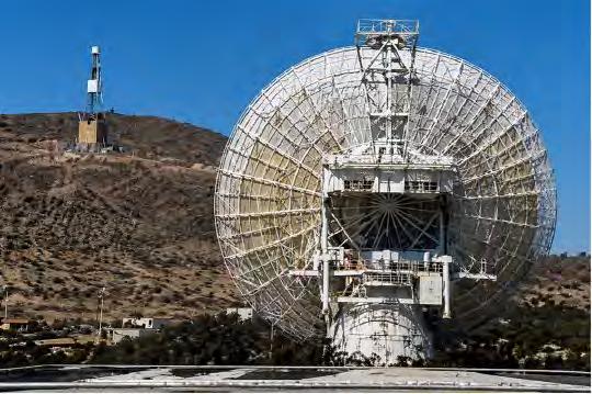
FIGURE 4: Seminal 1975 PTG experiment using a Goldstone NASA antenna (in stowed position) to transmit high power, taken to DC by a distant rectenna (shown left). NASA credit.
by increasing the number of elements rather than increasing the power handled by any single device.
Transmission technology took its design knowledge from established antenna and radar systems. Phased arrays provided a means of forming and steering microwave beams electronically, with beamwidth determined by the ratio of wavelength to aperture size. In the PTG context, these arrays were scaled to large physical dimensions to produce narrow beams over long distances. The underlying principles were well understood, and the primary challenge, naively, was seen as one of scale and implementation rather than of fundamental capability.
An integrated demonstration of microwave power transmission was conducted in 1975 at Goldstone by NASA Jet Propulsion Laboratory. In this experiment, tens of kilowatts of microwave power at approximately 2.4 GHz were transmitted over a distance of about 1.6 kilometers and received by a rectenna array, which converted the energy back into electrical power (see Figure 4). The demonstration (Dickinson, 1975) included beam formation, transmission, and reception, confirming that the complete chain could be realized in practice, though at a scale far below that required for space-based systems.
Subsequent work in Japan, led by JAXA and its predecessor organizations, continued the development of microwave power transmission systems (Nakamura et al., 2017). These efforts focused on phased array control, lightweight antenna structures, and rectenna performance, with both ground-based experiments and conceptual space-based designs. European studies under European Space Agency (Cougnet.,et al,2004). examined similar architectures, often emphasizing modular construction and incremental deployment strategies. Across these programs, the same system elements appeared consistently, and their individual operation was progressively refined.
Despite this continuity of development, we have no working PTG from the sky after some 50-plus years. The reasons are not found in the absence of components, but in no small part, the manner in which those components were treated. The collector, transmitter, and receiver were often developed and evaluated as separate subsystems, each optimized according to its own criteria. System-level integration was considered but not consistently enforced as the primary design constraint across all elements simultaneously. Large, expensive, and beyond existing capabilities, these components were optimized for intent but failed to attract sufficient commitment to execution.
The result is that PTG has remained a system in pieces and experiment rather than a system in operation. The path has been opened but not closed. What has been missing is not physics, nor devices, but a design discipline that treats the system as a single geometric and energetic entity, governed by aperture, matching, and scale from the outset. Until that closure is imposed—until collection, transmission, and reception are solved as one problem rather than three—
the system will continue to exist as demonstration, not infrastructure.
UNVEILING THE IMPORTANCE OF APERTURE
The objective of PTG systems can be stated directly: A space-based PTG system must deliver power to the ground at a scale and density that is competitive with, or exceeds, terrestrial solar generation. A large ground-based solar installation typically delivers average power density on the order of 10’s of W/m² when averaged over time, accounting for intermittency and atmospheric effects. A space-based system operates in continuous solar flux and is not subject to these constraints. The objective is therefore not to replicate terrestrial solar performance, but to exceed it, or augment it, delivering an aggregate time-averaged power density at the ground.
PTG can replace ground solar or be part of a hybrid which aggregates solar and PTG.
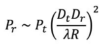
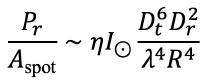
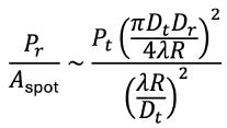
This PTG objective can be expressed directly in terms of the transmission geometry. The received power follows the well-known Friis path link relation, and in aperture form it depends on the product of the transmit and receive apertures, and inversely on wavelength and range. In its idealized form for circular apertures, received and transmitted powers are related by
As shown by this equation, aperture is not a convenient description—it is built into the equation governing the system, in the form of diameter as the parameter. Thus the system makes explicit use of surface area (as espoused by diameter) at both ends, and the coupling between those surfaces determines the outcome. For PTG,this equation is the personification of the saying ‘form follows function’.
Aperture defines the scale of the system. Delivered power and power density are set by how that power is distributed over area at the receiver. If the receiving area is constrained to practical dimensions, the transmitting system must be sized accordingly.
Cost follows from this directly. The dominant elements of the system are large-area constructions—solar collectors, transmit apertures, and rectenna fields—and their extent defines both capability and cost.
What remains is a review of how this equation defines a systems engineering approach on what has otherwise been a series of individual components, not unified in platform, but only serially concatenated in purpose. Disturbing that assumption frees up a new and important design space for PTG called the ‘aperture engine’.
THE APERTURE ENGINE: UNIFYING THE SYSTEM
Prior efforts on a PTG system carried systems engineering by distinct components. Even in Glaser’s original conception, the microwave antenna is separated from the solar panels, treated almost as an appendage, with distinct components attached. But structure carries consequences, and that consequence is decisive: here we show the system need not be defined by virtue of separate components, but by its surface. It is parametrized by area. It is defined by aperture.
The historical path has produced the components of PTG but has not closed the system. The elements exist, and their operation is understood, but they have not been assembled in a way that resolves the transfer of power from source to ground as a single construction. The missing element is not a device, but a definition of the system itself.
The aperture engine is that definition.
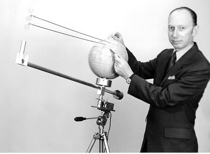
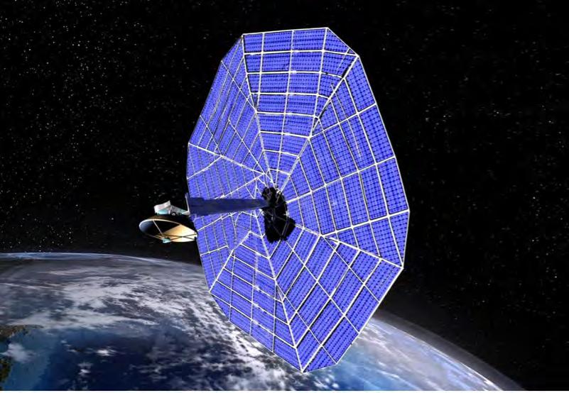
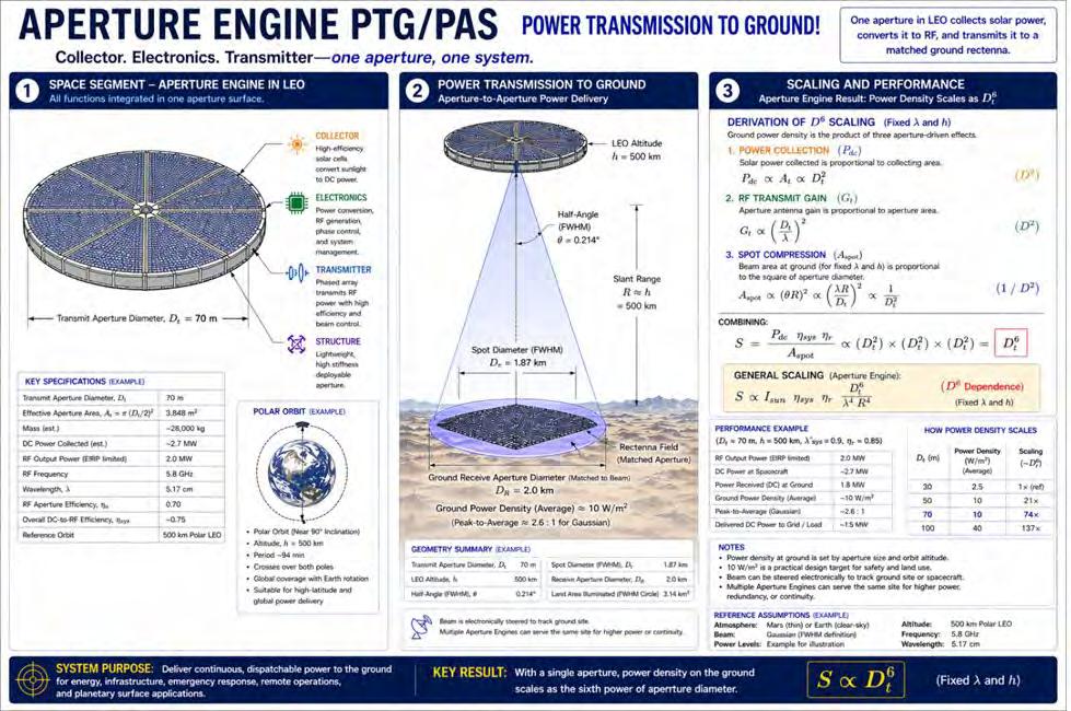
Formally, an aperture engine (Cohen, 1998) is a surfacebased power system defined by aperture, that takes solar radiation and, through layers of relevant electronics, converts that into RF power for transmission. Antenna and solar collector are not separate manifold surfaces; they are the same surface acting in different roles with built in energy conversion. Hence an ‘engine’. See Figure 5.
Taken into the realm of the PTG pipe, the solar collector, the transmit antenna, and the ground receiver are not independent subsystems. They are not separate components acting in isolation, but surfaces that define a single energytransfer structure. Power is collected over area, formed by
area into a beam, and recovered over area at the ground. It is an aperture engine which starts with sunlight, converts to electricity, transmits as RF, is collected as RF, and converted again to electricity. In all stages it is surface— aperture—which is the defining factor of the system.
Unlike prior PTG designs, a PTG aperture engine never concentrates power on itself. In comparison a prior PTG system cranks overwhelming power into an antenna feed component, as an example of a dubious systems approach. The surface of an aperture engine with all its functional components, never experiences a concentration of power density beyond the solar constant value, and the concentration of power, elsewhere, happens by virtue of the surface acting as a phased array at the far field. Concentrated power is at the ground, not at an aperture engine component. Certainly in-line power storage articulates a need for on board power aggregation but the aperture itself, in its functions, never experiences concentrated power. Because prior PTG designs, such as lasers, concentrate power within one or more components of the system, they experience severe problems with thermal management and inefficiency. Not so with a PTG aperture engine. This is a major design advantage of aperture engines, not previously articulated in PTG designs.
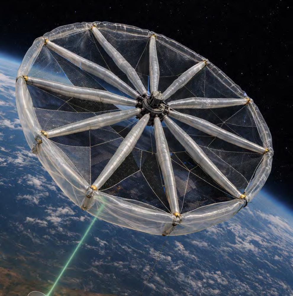
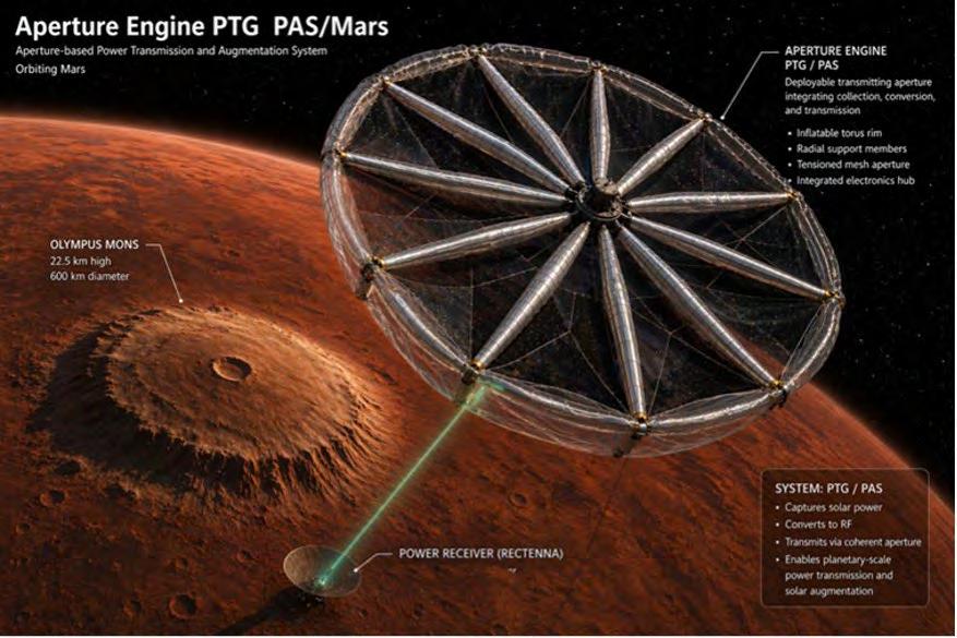
Aperture engines naturally prevent failure from high power concentration in components because no component is distinct and separate, nor experiences high power aggregation. See Figure 6 for a depiction of a PTG aperture engine, in this case a proposed one for Mars power delivery.
A PTG system is not defined by total received power, but by delivered power density at the ground. Here’s why. The beam defines a spot. The system resolves in power per unit area within that spot. We define the solar constant as such a power density. We continue that same framework in assessing PTG as a system. Can we quantify a PTG aperture engine by its power density?
This key role of surface emerges directly from an equation that governs power transfer through the PTG pipe. The
FIGURE 5: Cohen’s 1998 publication of an aperture engine broadly defined a new class for power in space. In PTG surface acting as both solar collector and directional antenna with a sandwich structure for power conversion and electronics. On right, sandwich is split to show antenna section (bottom). Author credit.
parameters are not arbitrary; they are imposed by the physics. It is easy to lose their physical meaning in abstraction but taken together they point to a single quantity: aperture. The derivation follows in the attached Appendix.
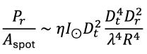
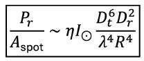
From this mathematical analysis , we see that when the transmitting aperture is also the solar collector, the system reduces to a single relation with an unexpected non linear advantage. It is defined here as the Aperture Engine Power Density Equation:
where, I⊙is the solar constant in W/m², and η is an efficiency factor. Note energy conservation restricts utility of the equation to where the received power is less than the transmitted power: increasing receive diameter cannot increase coupling beyond unity.
The sixth-power dependence is dictating the importance of aperture. It is neither intuitive nor trivial to see aperture articulated in the equation. The transmitting aperture
appears three times in the system, and each appearance is physically distinct. As a collector, it sets the amount of solar power gathered, scaling as D t 2. As a transmitting aperture, it determines the gain of the beam, contributing another D t 2 . Through diffraction, it also sets the size of the ground spot; increasing aperture reduces that spot, introducing a third D t 2 factor in power density. These are not separate effects arising from distinct components, but the same surface acting in different roles. Their combined action produces the D t 6 dependence. This is the key result.
What are normally treated as separate processes— collection, antenna gain, and beam spreading—are here shown to be inseparable. They are different expressions of the same geometry. Once this is recognized, the wireless pipe is no longer a sequence of components, but a single geometric system defined by aperture.
In this system, the transmitting surface aperture determines the structure of the pipe. It sets how much energy enters the system, how that energy is directed, and the size of the region over which it is distributed at the ground. The receiving aperture does not independently define the system; it samples it. Its role is to capture a portion of a spot that has already been determined by the transmitting
FIGURE 6: A small, inflated balloon-supported aperture engine acts as PTG to Mars in a possible future embodiment, in this artist depiction. Aperture engines do not aggregate power on components; the power concentrates in the far field via the RF antenna array. Author credit.
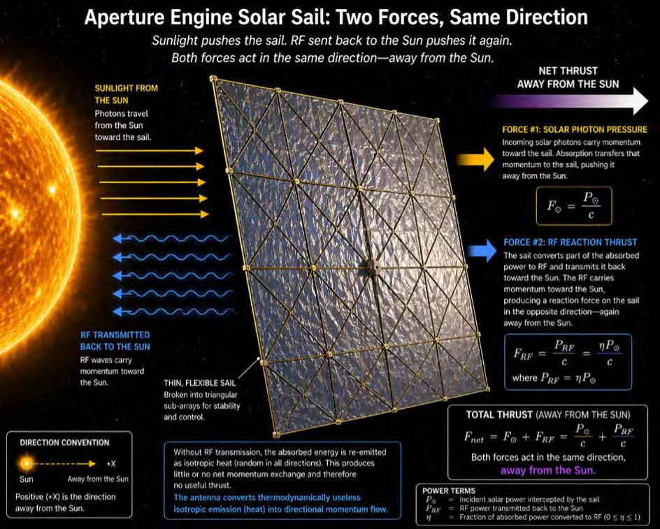
Solar Sails with Aperture Engines: the RF Bonus
An aperture engine collects solar radiation over an area A, converts part of that energy into electrical power, and transmits part of it as a directed RF beam. Because electromagnetic radiation carries momentum as well as energy, this process produces forces on the structure. The surface is not only a power-transfer system; it is a momentum-exchanging system.
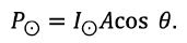
Let the incident solar flux be I⊙. The power intercepted is
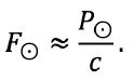
Photons carry momentum p=E/c, so the incoming solar radiation produces a force on the surface
This force acts away from the Sun. Absorbing the photons in the photovoltaic layer does not reduce this effect; it defines it. The surface is pushed simply by receiving energy and momentum from the incident radiation.
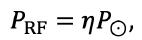
A fraction η of that absorbed power is converted into RF and transmitted from the same side of the surface that receives the sunlight. If the RF beam is directed back toward the Sun, then
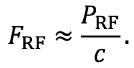
and the emitted radiation carries momentum toward the Sun. By conservation of momentum, the structure experiences a recoil force in the opposite direction, again away from the Sun,
The two effects act in the same direction. Incoming sunlight imparts momentum to the surface, and the transmitted RF beam carries momentum back toward the source, producing a second reaction force. The same photons are first absorbed and then re-emitted in a controlled form, and both processes contribute to thrust.
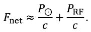
The resulting net force is therefore
Both terms point away from the Sun. The first arises from the absorption of incident solar photons. The second arises from the reaction to RF emission directed back toward the Sun.
In the absence of directed transmission, the absorbed energy must still be re-emitted, primarily as thermal radiation. If that emission is approximately isotropic (heat), it produces little or no net momentum exchange and therefore contributes negligibly to thrust. The system remains driven only by the direct radiation pressure of the incident sunlight.
The antenna changes this fundamentally. By converting absorbed energy into a coherent, directed electromagnetic beam, it imposes a preferred direction on the outgoing momentum flux and creates an additional, useful recoil force aligned with the solar radiation pressure.
The antenna converts thermodynamically useless isotropic emission (heat) into directional momentum flow. Small steps, but continuous ones.
In practical terms, sunlight pushes the system away from the Sun, and the RF transmitted back toward the Sun pushes it away again. The two contributions add. This is propulsion derived entirely from electromagnetic momentum exchange, requiring no propellant, only the controlled absorption and re-emission of radiation.
FIGURE 7: Possible higher powered aperture engine PTG for Earth, with some estimate of parameters. Larger aperture engines can easily exceed solar farm outputs. The concept also allows a more practical augmentation of retrofitted existing solar farms. Author credit.
surface. The system is therefore governed by a single aperture-defined geometry in which the transmit surface sets the system and the receive surface sets the fraction recovered.
The implication is immediate and non-linear. Doubling the transmit diameter increases the delivered ground power density by a factor of sixty-four. This is not incremental scaling. It is a regime change. The system objective does not respond linearly to size; it accelerates with it.
An important aspect of this equation is that it simplifies when the diameter of the ground spot matches the diameter of the illuminating beam. In this matched case, the coupling removes the separate receive diameter dependence and the expression becomes dependent only on the transmit diameter as D_t^4. Matching thus simplifies the system to a single transmitted aperture, and the power density scales as the fourth power.
This matched case, where coupling removes the independent receive diameter and the expression reduces to a fourth-power dependence on transmit diameter, is the typical regime considered in estimating PTG performance. These prior efforts separated collection from antenna and therefore did not produce a fourth-power dependence on
transmit aperture diameter. That dependence arises only when both functions are unified on a single transmitting surface.
Aperture-coupled or matched, the power density increases dramatically, following a power-law dependence on transmit aperture. The multiple roles of the transmit aperture give rise to this high-order power-law scaling, inviting exploitation.
This is why the aperture matters.
The transmitting surface is not simply part of the system. It gathers power from the solar flux, forms that power into a directed beam, and compresses that power into the ground spot defined by diffraction. Power, efficiency, and transmission alone do not define the outcome--the aperture does.
The consequence follows directly. Increasing delivered power density does not require increasing intensity within the beam, as experienced by the machinations of the antenna alone. It requires increasing the scale of the transmitting aperture. The receiving aperture then determines how much of that beam is captured and must be sized accordingly.
DONOR GIFT: COMMEMORATIVE CODE PRACTICE OSCILLATOR
We all know that students today are often more interested in computers than wireless. As a result, the future of wireless depends on getting more youth interestesd in wireless.
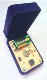
Here is a great opportunity to support our RCA Youth Program under Director Carole Perry and obtain a free gift as a result. Carole has been driving our Youth Program for 30 years this year! As a surprise to her, Director Charles Kirmuss commissioned a CW Morse code practice oscillator that was the same design Carole used years before with her early amateur radio classes with middle school and high school.
If you donate at least $30 to Carole's RCA Youth Program, you will receive a commemorative code practice oscillator. Your donation will be used to assist with costs like awards to the children, donation materials for school radio clubs, travel expenses for youth presenters to the Technical Symposium, and more.
In addition, if you renew your RCA membership for three years, you will also receive a code practice oscillator.
If you have interest in donating to the Youth Program, please email Director Carole Perry directly (wb2mgp@gmail.com) and she will provide instructions as to how to send a check.
If you wish to renew your membership for three years, contact Amy Beckham (Amy@radioclubofAmerica.org) for details on getting the code practice oscillator.
The system scales through area, and its performance follows from that scaling.
This resolves the historical incompleteness. Previous approaches treated collection, transmission, and reception as separable problems—defined by virtue of separate components. In the aperture engine, they are one mechanism. The same surface that gathers energy defines how it is delivered. The beam is the geometric expression of the system.
Because the system is governed by surface area, it can be realized as a multi-use structure. The system grows by replication of surface, not by increasing the burden on individual components. Once this is recognized, the wireless pipe is no longer a sequence of components, but a single geometric system defined by aperture. The aperture engine is not an addition to the PTG system. It is the system expressed in its proper form.
Figure 7 gives a summary and notional view of an aperture engine PTG system.
LET THE NUMBERS DEFINE THE SYSTEM
What can a PTG aperture engine tell us about how best to use the pipe? Let us explore some numbers and their implications.
For illustration, two RF wavelength regimes are considered. The first, at 6 cm, represents the conventional microwave region. The second, at 0.9 cm, lies within the satellite communication bands. This choice is deliberate. It occupies a notch of relative atmospheric transparency adjacent to the strong water vapor absorption band near 1.35 cm. It is not lossless, but it is usable, and it reduces diffraction substantially. The trade is explicit: accept a modest atmospheric penalty in exchange for a meaningful reduction in required aperture.
The receiving aperture is taken as a 500 m diameter rectenna field, comparable in scale to a moderate solar farm. The transmit aperture is then determined directly from the aperture engine power density relation. Two orbital regimes are considered. Geostationary orbit provides nearcontinuous solar access and fixed geometry relative to the ground, interrupted only by brief eclipse periods. A low Earth orbit at approximately 600 km reduces range by nearly two orders of magnitude, but provides only partial coverage at any given location. These are not incremental variations of a single design. They represent fundamentally different system realizations under the same governing relations.
The listed power densities range from 10 W/m² to 300 W/ m² at the ground. These values span PTG operating regimes, from augmentation of existing solar farms to dedicated power delivery at scale, all within the same receiving footprint.
GEO CASE (R ≈ 36,000 KM)
Target power density S D t at 6 cm D t at 0.9 cm
10 W/m²
30 W/m²
100 W/m²
300
At geostationary orbit, the numbers are set by range. Even at shorter wavelengths, the transmitting surface remains on the order of kilometers. This is not a design refinement; it is imposed directly by diffraction at distance. The advantage of GEO lies in continuity. The platform remains fixed relative to the ground and operates with near-constant access to solar flux. The system is large, but it is persistent, stable, and capable of continuous delivery.
LEO CASE (R ≈ 600 KM)
Target
10
30
100
300
At low Earth orbit, the same physics produces a system of a different scale. Note that the system remains aperturegoverned across the relevant propagation regimes. The reduction in range reduces the required transmit aperture by nearly two orders of magnitude. At 0.9 cm, the transmitting surface falls into the tens-of-meters class. These are not speculative structures. They are within reach. The cost of this reduction is coverage. A platform at 600 km does not remain fixed relative to the ground, and any given site is illuminated only intermittently. Continuous delivery therefore becomes a matter of system design, not a limitation of the physics.
These tables do more than illustrate scaling. They define the regimes.
At GEO, the system is aperture-limited and continuous. At LEO, it is coverage-limited and intermittent. The aperture engine does not remove this distinction. It makes it unavoidable. The choice between regimes is therefore not a matter of preference, but of what aspect of the system one chooses to carry: aperture scale or coverage complexity.
The decisive result appears in the lower left of the LEO table. At 0.9 cm and 600 km, a transmitting aperture on the order of tens of meters produces ground power densities on the order of 10 W/m² over a 500 m receiving field. This is not an extreme condition. It is a modest one, achieved without large structures or elevated intensities. It is directly compatible with augmentation of existing solar generation, which itself is typically, on average 10-20 W/m².
At this point, the governing constraint emerges. Ground power density is not limited by what can be transmitted,
but by what can be tolerated. Values on the order of 10 W/ m² define the practical operating regime for broad terrestrial deployment due to exposure considerations. Once this constraint is applied, the system no longer advances by increasing intensity. It advances by increasing area and maintaining continuity.
This places the system in direct comparison with terrestrial solar generation. As moderate-scale solar installation delivers time-averaged power densities on the order of tens of watts per square meter, there are thousands of such installations already in operation, occupying land, connected to the grid, and producing power at scale.
The implication is immediate and consequential. A PTG system operating within exposure limits can deliver continuous power at a comparable areal density to existing solar farms. It does not need to exceed them in instantaneous intensity. It only needs to match them in average delivery while operating continuously to manifest utility.
From this follows a different architecture.
PTG does not compete with solar farms. It augments them. Existing solar installations can be retrofitted with rectenna
RCA Mentorship Program
A way to share your knowledge and experience, or learn from the best!
The new RCA Mentorship Program is designed to pair RCA members together, providing opportunities for young professionals to learn and emulate the experience of more seasoned RCA members. Several mentoring pairs have already been formed and more are being formed. Learn more on the RCA website.
structures, allowing the same land area to receive both solar flux and transmitted power. Under these conditions, total delivered energy per unit area increases substantially, and in many cases can approach a doubling of effective capacity without requiring additional land, siting, or grid integration. This is not a marginal improvement. It is a system-level shift.
The aperture engine does not enable high-intensity transmission. It enables safe, distributed, continuous delivery over large areas that already exist and are already in use. The system closes not by exceeding terrestrial power density, but by matching it continuously and adding to it. The numbers do not suggest a possibility. They establish a path, and that path leads to a practical system.
In Part 2, a viable aperture-based system is presented that implements this architecture with modest satellite constellations in low Earth orbit, and shows how PTG can be realized within less than a generation. These values are carried forward in Part 2 into system architectures, including efficiency, constellation design, and grid-level integration. The path to PTG will be detailed, as well as its challenges that lie ahead.
ACKNOWLEDGEMENTS
As a Viking Intern with the Radio Science team, I was privileged to work with Bill Michael (NASA Langley) and Mario Grossi (Raytheon), who challenged me to think about power to Mars and thus Earthly climes. With the 50th anniversary of Project Viking I dedicate this paper to their memory, with thanks. Ad Astra Per Aspera. On to Mars and power to all!
REFERENCES
Brown,W., “Experiments Involving a Microwave Beam to Power and Position a Helicopter.”
IEEE Transactions on Aerospace and Electronic Systems, Vol. AES-5, No. 5, pp. 692–702, 1969.
Cohen,N.,”Aperture Engines for SETI”, SetiQuest,4,3, 1011, 1998.
Cougnet.,C., et al., “Solar Power Satellites for Space Exploration,”
European Space Agency (ESA), Advanced Concepts Team (ACT),
ESA Report ACT-RPR-NRG-2004, 2004.
Dickinson,R., “Evaluation of a Microwave HighPower Reception-Conversion Array for Wireless Power Transmission,”
NASA Contractor Report NASA-CR-145625, Jet Propulsion Laboratory (JPL-TM-33-741), September 1975
Glaser, P., US Patent 3,781,647, Method and apparatus for converting solar radiation to electrical power, 1973.
Nakamura, S.; Maekawa, K.; Sasaki, K.; Mihara, S. “SSPS activities at Japan Space Systems.” Space Solar Power Systems, Vol. 2, pp. 6–9, 2017.
APPENDIX
The Friis equation related transmitted and received powers:
The delivered ground power density over the beam spot is:
The diffraction-limited beam spot diameter is given by diffraction optics:
so converting the area, the beam spot area scales as Therefore,
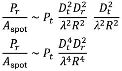
Collect terms:
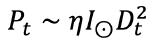
For an aperture engine the transmitted power is also tied into the diameter of the antenna aperture: The transmitting aperture is also the solar collector, so the transmitted power scales with collected solar power:
Substitute this into the previous result:
which yields
Why the sixth power appears It comes from three distinct roles of the same transmitting surface:
Those are:
• collection of solar power: D t 2
• transmit gain / beam formation: D t 2
• spot compression in power density through diffraction: D t 2 That is the Aperture Engine Power Density Equation.
November 16–19, 2026 Pasadena Convention Center
LIGHT AND SOUND: ARTEMIS II’s REVOLUTIONARY COMMUNICATIONS
By David Bart
NASA’s Artemis II mission on April 1–11, 2026, marked the first time in more than 50 years that humans have traveled to the Moon. This was the second flight of the Space Launch System (SLS) and the first crewed flight of the Orion spacecraft. Originally designated Exploration Mission-2 (EM-2), the mission was a test flight supporting subsequent Artemis missions to return humans to the lunar surface. The four-person crew named their ship Integrity.
The communications architecture for Artemis II bridges NASA’s 1960s heritage with the high-bandwidth, laser-driven future of deep space exploration.
MISSION OBJECTIVES
Distance, Objectives, and Orion
The Artemis II mission objectives resembled those of Apollo 8 in 1968, the first crewed lunar flight of the Apollo program, although the Artemis II free-return trajectory
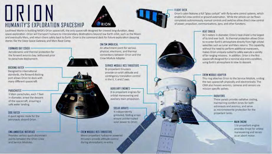
The Orion spacecraft. (Lockheed Martin)
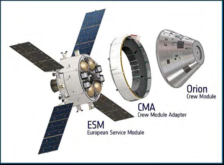
The three main components of the Orion spacecraft. (NASA)
resembled that of Apollo 13 in 1970. The Artemis II crew set the record for human distance from Earth at 252,756 miles (406,771 km), breaking Apollo 13’s record of 248,655 miles (400,171 km).
The Artemis II mission also tested significant systems necessary for returning to the lunar surface. The primary goal was to validate the Orion spacecraft’s systems, crew operations, and mission procedures ahead of sustained lunar exploration. These included complete tests of navigation, docking, life support, and other critical systems.
NASA’s Orion spacecraft is a deep-space vehicle designed for the Artemis program to carry astronauts to the Moon and beyond. “Integrity” is the specific name given to the Orion spacecraft, its callsign for the capsule, that was selected by the four-person crew to represent trust, respect, candor, humility, and integrated effort.
The Orion spacecraft has three main sections: the crew module (CM), where the astronauts live during the mission; the European Service Module (ESM), built by the European Space Agency, which provides all the consumables needed by the crew as well as power and propulsion; and the Crew Module Adapter (CMA), which connects the two. The complete service module includes ESM and CMA. The CMA houses avionics, communications, cameras, and sensors via mission-specific pallets. Four independently gimballed folding solar arrays provide power. Each solar panel is approximately 7 meters (23 feet) long. When fully deployed, the arrays span approximately 19 meters (62.25 feet) tip-totip, providing 11 kW of power.
MISSION CUBESATS
The Artemis II mission included the launch of CubeSats under NASA’s CubeSat Launch Initiative (CSLI) program. Five slots were available for CubeSats. Three CubeSats tested communications systems or the impact of space on electrical systems.
• The ATENEA satellite from Argentina’s National Space Activities Commission studied radiation shielding, mapped the surrounding radiation environment, gathered GPS data for mission planning, and tested a long-distance communication system.
• SHAMS (or SHMS, also referred to as Space Weather CubeSat-1), which means “Sun” in Arabic, is a mission from the Saudi Space Agency that measured aspects of space weather in high Earth orbit.
• Germany’s TACHELES examined the impact of space conditions on electrical components used in lunar vehicles.
• The K-RadCube from the Korea Aerospace Administration studied a material simulating human tissue for the effects of space radiation.
• The fifth CubeSat slot was occupied by an avionics unit. ATENEA and SHAMS completed their objectives. The other two were unable to raise their perigee and stay in orbit.
COMMUNICATIONS CHALLENGE
A number of challenges for improved space communication remained after the Apollo program. Apollo’s lunar television was restricted by the requirement to operate with minimal power while transmitting over 240,000 miles. NASA engineers used a non-standard slow-scan format of 10 frames per second at 320 lines of resolution. This was far below the commercial television broadcast standards of the time, with 30 frames per second at 525 lines of resolution. The grainy, shadowed footage that television audiences remember seeing resulted from signal degradation and multiple signal conversions. The original signals from the lunar surface traveled tremendous distances and underwent numerous data conversions over microwave links and analog phone lines on their way to Mission Control, then back out through television broadcasters. A half-century later, the Artemis program developed a dual radio frequency/digital approach to overcome or bypass many of these issues.
CORE STAGE COMMUNICATIONS
The Artemis II SLS core stage, engines, boosters, and Interim Cryogenic Propulsion Stage (ICPS) all have computers and software that monitor and control their functions.
Of the many systems, the flight control system, led by three redundant flight computers, monitors the rocket’s condition, senses vehicle motion, generates navigation and control data,
Core stage avionics throughout the elements of SLS monitor the rocket’s health and control the flight. (NASA)
operates main propulsion-system valves, monitors the main propulsion system and engine controls, and routes flightcritical commands to engine thrust vector control systems and controllers. The flight computers each have 256 MB of RAM, and the primary flight computers manage over 750,000 lines of code that govern critical systems, including guidance and communications.
The core stage telemetry system includes radio and Ethernet communications with the ground, telemetry control, engineering and development flight instrumentation, and a motion imagery system.
ONBOARD COMMUNICATIONS
Onboard Artemis II, a primary audio system enables the crew to speak with each other and with the Mission Control Center while wearing their spacesuits, as well as during the in-orbit mission phase while in shirtsleeve operations. An emergency communication system allows two-way voice communications during the mission if the primary communications system fails. Search-and-rescue radios and satellite phones were available after landing for communication with the recovery team.
L3Harris supplied the NASA Orion audio system, facilitating clear, continuous voice communication between the astronauts and mission control in Houston. Inside the capsule, the astronauts used handheld microphones, speakers, and headsets. They also used Microsoft Surface tablets, known as Personal Computing Devices (PCDs), to access flight procedures, review plans, and manage data. The audio system included:
• redundant internal and external crew communications, voice recording and playback, and the audio interface for search-and-rescue operations.
• an Audio Control Unit (ACU) featuring five voice channels for communication flexibility, low power consumption, and increased efficiency with 13 alarms for real-time situational awareness.
• a Speaker Unit (SU) that provided the audio output.
• an Audio Interface Unit (AIU) that clipped onto each astronaut’s suit, providing a configurable, voice-activated feature for hands-free operation.
These audio systems worked with data systems that incorporated the Time-Triggered Ethernet (SAE AS6802, TTEthernet, or TTE) standard, which provided a fault-tolerant synchronization strategy for maintaining time synchronization in Ethernet networks. TTE outlines synchronous, timetriggered packet switching for critical integrated applications, such as integrated modular avionics (IMA) architectures. SAE International released TTE in 2011, and TTTech Aerospace developed its own deterministic version for NASA applications.
In Orion, TTE carried data between the spacecraft’s systems and its external communications hardware, connecting nearly 50 communications endpoints. Data rates reached 1,000 Mb/s, allowing Orion to handle numerous flight-
critical functions such as life support monitoring, navigation, and propulsion control on the same physical network infrastructure as less time-sensitive data, such as imagery and crew voices. The use of deterministic scheduling ensured that safety-critical data always received priority.
REMOTE COMMUNICATIONS WITH EARTH
Artemis II: A Hybrid Approach
Artemis II upgraded Apollo’s original radio systems and introduced an entirely new medium: laser light. The mission combined these two systems, incorporating a hybrid approach that modernized the S-band radio system with a revolutionary laser terminal.
Antennas
Orion used a high-speed communications system that employed four S-band phased-array antennas (PAA) on the crew module and two on the service module. PAAs provided the primary link for voice, video, and high-rate data. These antennas delivered a near-continuous connection with Earthbased networks throughout the mission.
Phased-array antennas allowed signals to be controlled and directed without requiring any physical movement of the antennas. The four phased-array antennas provided overlapping 360-degree coverage around the capsule, relying on electronic control to detect radio signals. The four separate antennas provided redundancy and ensured uninterrupted communication even as the spacecraft rotated or maneuvered.
The antennas, developed by BAE Systems (formerly Ball Aerospace), were integrated directly into the CM, allowing them to remain operational even after the ESM and CMA were jettisoned before re-entry. The PAAs were successfully flight-tested during the Artemis I mission in 2022. The PAAs are some of the few parts of the Artemis I spacecraft that were reused for the Artemis II mission to reduce costs and leverage proven hardware.
The PAAs were used for video, data, and voice communications with the spacecraft, as well as command uplinks, telemetry downlinks to ground stations, and live video/voice feeds for the four-person crew. NASA’s Tracking and Data Relay Satellite (TDRS) systems and NASA’s Near Space Network (NSN) and Deep Space Network (DSN) maintained contact with Earth.
Two additional S-band antennas were located on the ESM, providing high-gain communications during transit to and from the Moon.
Apollo and Unified S-band (USB)
During the Apollo era, communication relied on analog engineering, which tested the raw endurance of equipment and systems. To consolidate telemetry, voice, and television into a single stream, NASA developed the Unified S-band (USB) system.
Before USB, spacecraft required multiple antennas and frequencies for different tasks: VHF for voice, UHF for tracking, and different bands for telemetry. Apollo combined
these into a single “unified” frequency of approximately 2.106 GHz (uplink) and 2.287 GHz (downlink).
• Data Rates: Apollo’s maximum downlink speed was only 51.2 Kb/s, slower than a 1990s dial-up modem.
• Television: Video from the Moon was transmitted in a slow-scan format with 10 frames per second at 320 lines to fit within the narrow signal bandwidth.
• The Network: The Manned Space Flight Network (MSFN) relied on 26-meter (85-foot) antennas spread across the globe to ensure at least one station always had a line of sight to the Moon.
Optical Communications System (O2O)
Artemis II communications introduced the new O2O system. S-band continued to provide mission-critical radio links to the spacecraft, but O2O enabled much faster communication and the transmission of large amounts of data via optical systems.
The OCU (Optical Communications User Terminal) refers to the broader, operational role of the O2O hardware. OCU is often referred to within the context of the “OpCom” payload or terminal, serving as the “user” terminal that establishes a “transparent Ethernet bridge” to send data.
• Operational Role: Because light has a much higher frequency than radio, it can carry significantly more data, which is necessary for handling high-resolution images, flight procedures, and real-time voice communication, video conferencing, and mission management.
• Mechanism: O2O pulses infrared lasers with a wavelength of 1,550 nm (nanometers), a frequency of approximately 193 THz. O2O uses the Modular, Agile, Scalable Optical Terminal (MAScOT) to enable highspeed laser communications.
rendering of
• Performance: O2O achieves downlink speeds of up to 260 Mb/s and uplink speeds of 20 Mb/s; over 100 times faster than conventional radio networks and nearly 5,000 times faster than Apollo’s peak capability.
• Capacity: This bandwidth allowed the Artemis II crew to transmit 4K ultra-high-definition live video in real-time and to send large science files that would have taken days to download via radio.
Funded by the Space Communications and Navigation Program (SCaN) and undertaken by the Exploration and Space Communications (ESC) projects division, O2O transmitted science data, procedures, flight plans, communications, and served as a vital link between Orion and mission control on Earth.
NASA’s Goddard Space Flight Center in Greenbelt, Maryland, manages the Orion Artemis II Optical Communications System. O2O was developed by a team of engineers from NASA’s Goddard Space Flight Center and the Massachusetts Institute of Technology Lincoln Laboratory. The partnership has led to multiple laser communications missions, such as the 2013 Lunar Laser Communications Demonstration (LLCD), the 2021 Laser Communications Relay Demonstration (LCRD), and the 2022 TeraByte InfraRed Delivery (TBIRD) payload. SCaN has demonstrated the benefits of laser communications for mission communications.
On April 4, 2026, the fourth day of Artemis II’s 10-day mission, NASA announced the O2O system’s success. In less than four days, O2O had already downlinked 100 GB of data, while the spacecraft was approximately 169,000 miles from Earth.
Radio and S-band: The Reliable Backbone
Despite the allure of lasers, the S-band (2.2–2.3 GHz) radio frequency remained the primary link for mission-critical commands and astronaut health data.
• Apollo’s vs. Artemis II’s S-band: While the frequency bands are similar, Artemis II used digital modulation and sophisticated encryption. Where Apollo’s signals could technically be eavesdropped and monitored by large
Orion O2O optical module. (NASA)
Artist’s
Orion’s O2O Optical Module sending laser pulses to Earth. (NASA)
amateur dishes, Artemis II’s signals were highly secure digital packets that utilize proprietary digital modes.
• Ka-band: For higher-speed radio data, Orion also utilized Ka-band frequencies (26–40 GHz), which offered more bandwidth than S-band but were more susceptible to atmospheric interference.
Even while recognizing the basic strengths of radio, Artemis II moved beyond its limitations by using optical lasers, achieving a massive increase in data transmission rates from the 51.2 Kb/s reached in the Apollo era.
Orion’s primary S-band radio link provided a downlink data rate of approximately 1–2 Mb/s from lunar distances, sufficient for telemetry, crew voices, and compressed imagery, but insufficient for uncompressed high-resolution video or large data files.
At these speeds, data compression is essential. When large volumes of data reach Earth using S-band radio, it arrives faster than the DSN’s capacity for uncompressed playback. For the Artemis II mission, NASA compressed the data stream reaching Earth to manage the volume. Data compression reduced image and video quality, but prioritized bandwidth for crew voice communications and mission health data. NASA traded high-resolution images for the more critical voice and telemetry.
In addition to S-band, Orion carried a UHF communications system for proximity operations. The UHF system is expected to become more important in future missions. The UHF system is intended for short-range communications when operating near other vehicles (such as docking with the lunar module or a space station) or during spacewalk activities.
Lasers
O2O is officially classified by NASA as a Detailed Test Objective. NASA is still assessing its operational utility in a human-crewed deep-space environment and is not relying on it for anything mission-critical. The Artemis II mission demonstrated that lasers successfully provided benefits over radio, making this technology a complementary alternative.
Laser communications (optical comms) solved the so-called spectrum crunch. Radio frequencies have limited bandwidth and are crowded. Lasers offered a more robust solution. Computer-based avionics significantly enhance accuracy, reliability, and safety in space travel by replacing manual, analog, and mechanical systems with high-speed digital processing.
Radio waves spread as they travel. Radio signal beam divergence measures the rate of angular increase in a radio wave beam’s diameter (or radius) as it travels away from a transmitter antenna. This is the natural spreading of electromagnetic energy over a larger area as the signal propagates through space, resulting in a decrease in power density (signal strength) at the receiver. A radio signal transmitted from the Moon becomes wider than the Earth by the time it arrives. When a radio signal from the Moon reaches Earth, it is 2.5 million km (1.5 million miles) wide and significantly weaker, with a path loss of approximately 200–210 dB at common microwave frequencies.
In contrast, a laser beam remains tight, with low divergence over long distances. A tighter beam preserves transmitted energy but requires greater accuracy when pointing toward a receiver. On the Orion spacecraft, this requires the two-axis gimbal to point the laser with extreme precision. Upon arrival at a target ground station on Earth, 240,000 miles away, the laser beam is approximately 6 km (3.75 miles) in diameter, with approximately one milliradian of pointing accuracy. This is analogous to hitting a three-foot target from over eight American football fields away. Once pointing accuracy is achieved with the aid of computer-based avionics, the laser system becomes a viable, more precise alternative to radio. The laser terminal on the spacecraft is small (about the size of a house cat). It pulses infrared laser light using a very precise 4-inch telescope to aim the beam from lunar orbit. The 4-inch telescope is mounted on a two-axis pivoted support (gimbal) with fixed backend optics. The gimbal precisely points the telescope and tracks the laser beam toward the desired data recipient. The backend optics, which include light-focusing lenses, tracking sensors, fast-
Apollo vs. Artemis II Communications
S-band (Analog/Digital)
Downlink Speed~51.2 Kb/s
Video Quality Slow-scan, B&W/Grainy Color
Pointing AccuracyLow (Wide radio beam)
Security Unencrypted / Open
Network
Ka-band, & Optical (Laser)
to 260 Mb/s (Laser)
Ultra-HD
(Narrow laser beam)
Encrypted / Digital
(Manned Space Flight Network)Deep & Near Space Networks
steering mirrors, and other components that finely point the laser beam, are located beneath the gimbal in a separate assembly.
The small O2O system uses a lighter, smaller terminal than traditional radio systems. O2O terminals also consume less power than radio transmitters with equivalent data rates. These features offer higher payload efficiency by saving precious mass onboard the spacecraft, leaving more room for scientific equipment.
MODERN GROUND INFRASTRUCTURE
The ground segment has evolved from the fragmented Manned Space Flight Network (MSFN) of the 1960s into a seamless, integrated global network managed by NASA’s Space Communications and Navigation (SCaN) program.
Deep Space Network (DSN)
The DSN is the primary means of receiving the signals from the Artemis II mission once it leaves Earth’s orbit. The DSN is managed by NASA’s Jet Propulsion Laboratory in Southern California. It consists principally of three giant 70-meter (230-foot) radio antennas spaced roughly 120 degrees apart, providing a near- continuous connection between Orion and Earth. Each site hosts multiple dish antennas:
1. Goldstone Deep Space Communications Complex in the Mojave Desert near Barstow, California
2. Madrid Deep Space Communications Complex near Robledo de Chavela, Spain
3. Canberra Deep Space Communication Complex located at Tidbinbilla, Australia.
For Artemis II, the DSN has been upgraded with new 34-meter (112-foot) antennas and cryogenic receivers to handle the digital complexity of the Orion spacecraft. The
Artemis II communications are mounted on the Crew Module Adapter of the Artemis II spacecraft, as seen during vehicle assembly. (NASA)
Artemis II avionics on the Crew Module Adapter of the Orion Artemis II spacecraft. (NASA/SPIE)
DSN was critical for re-establishing contact after Orion emerged from behind the far side of the Moon, where direct line-of-sight with Earth was temporarily lost.
DSN communicates on multiple radio frequency bands: S-band near 2 gigahertz, X-band near 8 gigahertz, and Kaband near 32 gigahertz. DSN has migrated toward X-band and Ka-band for high-volume data return, since higherfrequency bands carry more data per unit time for a given antenna size.
For Artemis II, Orion’s primary radio communications link operated in S-band, with a downlink data rate of
approximately 1–2 Mb/s from lunar distances. That was sufficient to carry telemetry, voice, and compressed imagery on Artemis II, but future missions will need to meet far more data-intensive demands.
Near Space Network (NSN)
During the launch and Earth-orbit phases, Orion communicated using the NSN, managed by NASA’s Goddard Space Flight Center.
NSN was originally developed to support the Space Shuttle program and now supports missions traveling within 1.25 million miles from Earth. This distance includes low Earth orbit, geosynchronous orbit, highly elliptical orbit, and lunar missions.
NSN operates a fleet of support satellites and more than 40 government- and commercially owned ground-station antennas.
• TDRS (Tracking and Data Relay Satellites): A constellation of satellites in geostationary orbit allowed Orion to communicate with the ground even when it did not have a direct line of sight to a ground station.
• Commercial Stations: Unlike the NASA-only Apollo era, the NSN now integrates commercial ground stations to provide continuous coverage. A global network of Earthbased antennas helps ensure seamless tracking during translunar injection and the final return to Earth.
The allocation of DSN and NSN coverage during the Artemis II mission depended on the spacecraft’s location and trajectory at any given time.
An antenna at the Goldstone Deep Space Communications Complex. (NASA)
NSN and DSN network utilization in the Artemis II mission. (NASA)
Optical Ground Stations (OGS)
Atmospheric conditions can pose problems for laser light, such as fog, rain, clouds, and humidity. Because lasers cannot penetrate these conditions, the O2O system requires specialized ground terminals in high-altitude, clear-weather locations. Orion’s O2O terminal must point its 4-inch telescope with extreme accuracy toward OGS while Orion is moving at thousands of miles per hour. NASA operates two primary OGS:
1. White Sands, New Mexico — operated by NASA/ Goddard Space Flight Center
2. Table Mountain, California — operated by NASA/Jet Propulsion Laboratory.
Other Ground Stations
An additional experimental OGS station at Mount Stromlo in Canberra, Australia, operated by the Australian National University (ANU), was available as a backup for the Artemis II mission. The European Space Agency (ESA) also operates an OGS at the Instituto de Astrofísica de Canarias in Tenerife, which was used to test and commission laser communication terminals on early Artemis satellites. The Goonhilly Downs Earth Station, located in Cornwall, UK, was actively involved in supporting the Artemis II mission. Its 32-meter (105-foot) GHY-6 satellite dish antenna provided critical communications and passive tracking services as the world’s first commercial deep-space ground station.
The Far Side Blackout
Despite these technological leaps, some basic physics remains unchanged. When Orion passed behind the Moon, it entered a shadow where both radio and laser signals to Earth were blocked by the Moon’s mass.
For Artemis II, this communications blackout lasted approximately 41 minutes. Unlike the Apollo astronauts, who were truly isolated during this time, the Artemis II crew relied on onboard autonomous systems that were far more capable than the 1960s flight computers, and they used the O2O system to send bursts of all recorded data immediately upon re-emerging into Earth’s view.
• Earthset and Earthrise: Just before the blackout, the crew witnessed Earthset (Earth dropping below the lunar horizon), and upon re-establishing communication, they viewed Earthrise, marking the beginning and ending of the blackout period.
• Scientific Observations: During the blackout, the crew took photos of the far-side terrain, including craters and mountain ranges not previously seen in person, and observed a total solar eclipse.
• Safety Procedures: While this was a planned communication outage and a critical moment where the crew is entirely independent, the spacecraft’s automated systems functioned independently before re-acquiring signals with NASA’s DSN.
NASA is working toward a solution to overcome the blackout period. The Lunar Communications Relay and Navigation Systems (LCRNS) project is collaborating with industry
partners to enable communications around the Moon by placing relay satellites in lunar orbit to provide continuous connectivity, even on the Moon’s far side. In 2024, NASA selected Intuitive Machines to develop the first set of lunar relay satellites. These are planned for demonstration during the Artemis III mission. A longer-term vision involves creating a lunar network, called LunaNet, to provide interoperability and GPS-like capabilities on the Moon.
Optical Ground Station at White Sands. (NASA)
Optical Ground Station at Table Mountain. (NASA)
NEW BEGINNINGS IN SPACE COMMUNICATIONS
Laser Technology on the Moon
The Artemis II mission is the first crewed mission to use lasers for high-definition data communication from the Moon to Earth, but it was not the first lunar mission to utilize laser technology.
The Apollo 11 mission deployed a retroreflector array on the Moon to receive laser beams from Earth for distance ranging. The Apollo 11 crew placed a Lunar Laser Ranging retroreflector on the Moon in 1969, enabling Earth-based lasers at Lick Observatory to pulse and reflect off the Moon to measure the distance. Fifty-five years later, Polaris Dawn in 2024 tested SpaceX Starlink laser-based communications in low Earth orbit. Artemis II in 2026 was the first human spaceflight mission to use laser communications in an operational role.
Several key successes paved the way for the use of lasers in Artemis II’s communications:
• 2013 — Lunar Laser Communications Demonstration (LLCD) — sent laser communications signals from the Moon at 600 Mb/s
• 2014 — Optical Payload for Lasercomm Science (OPALS) Experiment — a four-month laser communications demonstration onboard the International Space Station
• 2017 — Optical Communications and Sensor Demonstration (OCSD) — provided the first-ever highspeed laser communications downlink from a CubeSat to a ground station
• 2021 — Laser Communications Relay Demonstration (LCRD) aboard the International Space Station (ISS) — NASA’s first demonstration of a two-way laser relay system, operating in geosynchronous orbit, that provided a platform for testing how lasers handle atmospheric interference and communicating high-resolution images and videos of ongoing experiments to Earth from orbit
• 2022 — TeraByte InfraRed Delivery (TBIRD) mission — demonstrated burst-like laser downlinks of 200 Gb/s from low Earth orbit using CubeSats
• 2023 — Integrated LCRD Low Earth Orbit User Modem and Amplifier Terminal (ILLUMA-T) — NASA’s first endto-end laser relay by communicating with LCRD at 1.2 Gb/s downlink and 155 Mb/s uplink from ISS
• 2023 — Psyche mission — part of a 3.5-year journey to reach the Psyche asteroid, over 150 million miles from Earth, when, during the first year, the onboard Deep Space Optical Communications (DSOC) payload tested laser communications in deep space
On the Artemis II mission, the laser system could downlink data at speeds of 20–260 Mb/s, between 100–200 times faster than Orion’s S-band radio link, when operating at a lunar distance.
• With S-band alone, Orion’s data downlink is limited to approximately 7 GB of data per day, and Orion could not downlink all of its recorded data.
• With just 1 hour per day of O2O communications, Orion’s data downlink increased to approximately 36 GB of data per day, a six-fold increase per day.
• At 260 Mb/s, Orion’s downlink capacity increased to 117 GB per day, a twenty-fold increase.
• Two 1-hour transmissions at 260Mb/s per day allowed Orion to downlink 234 GB per day, enough to transmit all of its recorded data on the second day.
• The overall cumulative impact of O2O data transmission over multiple days climbs substantially.
Evolving Technologies
The evolution from Apollo to Artemis II is the story of a raw beginning that has matured into a deeper experience, taking the best of Apollo, the Space Shuttle, and other technologies and combining them with new advances specifically designed for Artemis to improve its safety and efficiency.
Notably, the Orion capsule is larger and can fit more crew members than Apollo. It is also much more technologically advanced. Apollo had only a single flight computer. Orion has two redundant flight computers operating simultaneously.
An IEEE Milestone plaque was dedicated on Aug. 1, 2019, at Lick Observatory on the 50th anniversary of Apollo 11. (IEEE)
The Apollo Lunar Laser Ranging retroreflector on the Moon. (NASA)
Feature
Apollo vs. Artemis II Spacecraft
(1969-1972) Artemis
Each of these includes two redundant computer modules, giving it a total of four redundant systems. One of Orion’s redundant computers has only three-quarters of the weight of Apollo’s sole computer. One Orion computer provides 128,000 times more memory and is 20,000 times faster than Apollo’s system.
LunaNet
The Artemis II mission was the next step in establishing a long-term presence on the Moon. The goal is to open the
lunar surface to greater exploration. This activity will require new, more robust technologies for lunar communications, navigation, and networking. The SCaN program is developing more standards and a new architecture to establish LunaNet, enabling the installation and rapid expansion of network capabilities on the Moon. International efforts to establish common standards for Lunar communications date back nearly 50 years. As a result of the expanded focus on the Moon and Mars, the Communications, Navigation,
LunaNet interoperability systems, showing the uses of RF, Navigational, and Optical communications. (NASA/Japan Aerospace Exploration Agency (JAXA))
Lunar surface operations of LunaNet, showing RF and Wi-Fi links. (NASA)
Positioning, and Timing (CPNT) architecture was renamed LunaNet in 2020.
The LunaNet framework is intended to allow industry, academia, and international partners to build and operate LunaNet nodes alongside NASA. These nodes will provide four distinct services: networking, navigation, detection and information exchange, and radio/optical science services. Draft interoperability specifications are already serving as a starting point for technical discussions among industry and government experts worldwide.
Traditional radio-frequency and Wi-fi are going to play important roles. For example, Nokia Bell Labs, in partnership with Intuitive Machines and NASA, is working to deploy the first cellular network on the Moon. NASA launched the Intuitive Machines IM-2 mission on February 26, 2025, and landed the Athena Nova-C lander on the Moon on March 6, 2025. This was part of NASA’s Commercial Lunar Payload Services (CLPS) initiative. IM-2 landed near the Moon’s south pole to search for water ice and test communication technology. The Lunar Surface Communications System (LSCS) is a 4G/LTE network designed to provide critical, high-speed, and reliable connectivity for lunar rovers, landers, and future human exploration. Unfortunately, Athena landed on its side, and one of the two radio antennas was inoperative, resulting in significant power limitations and reduced communication. Yet, it was a first step. The work goes on.
Projected communication needs are expected to exceed the planned radio-frequency communications capacity. The ability to send continuous data streams or bursts of significant data volume is a new asset to deploy. Therefore, planned optical communications capabilities are expected to augment RF by providing the higher data throughput needed to accommodate the increasing data volumes at the Moon and in long-distance Earth-Moon communications.
CONCLUSION
While communications from Apollo gave us a crackling voice and a grainy, shadowed image, the Artemis II mission provided a high-definition, data-rich experience that made the Moon feel like a part of our modern digital world. By blending the reliability of S-band radio with the revolutionary speed of laser communications, NASA is ensuring that the next “giant leap” onto the Moon by a human being is captured in 4K resolution, in Ultra High Definition (UHD). Artemis III’s planned landing on the surface of the Moon in 2027 should be spectacular!
SOURCES
Articles
[1] Bluestein, A., “How Artemis II is Beaming Back Stunning Video From The Moon,” Scientific American, Apr. 5, 2026.
[2] Gaines, A. and Parde, N., “Lincoln Laboratory Laser Communications Terminal Launches on Historic Artemis II Moon Mission,” MIT News, Apr. 2, 2026.
[3] “How the Artemis II Orion Capsule Maintains Communications With NASA,” New Space Economy, Apr. 4, 2026, https://newspaceeconomy.ca. Retrieved Apr. 19, 2026.
[5] Murphy, K., “NASA Laser Communications Terminal Delivered for Artemis II Moon Mission,” June 13, 2023, https://phys.org/news/. Retrieved Apr. 17, 2026.
[6] Todd, I., “Artemis II Will Broadcast 4K From The Moon— Laser Tech Could Give Us Netflix-Style Views of the Lunar Surface.” BBC Sky at Night Magazine, Apr. 2026.
Blogs and Website Articles
[7] “Artemis II Broadcast Pipeline: Laser Comms, 4K, And The Truth.” RedShark News, Apr. 2026, https://www. redsharknews.com. Retrieved Apr. 17, 2026.
[8] Basson, B., “Broadband from The Moon: How Artemis II Pushes NASA Beyond Apollo’s Radio Frequencies,” X (formerly Twitter) / Broadband Breakfast, Apr. 2026.
[9] Gerhart, D., KK7WXV, “Artemis II Radio Plan.” Coos County Radio Club, Feb. 28, 2026, https://coosradioclub. com. Retrieved Apr. 17, 2026.
[10] “Laser vs. RF: How Artemis II is Revolutionizing Space Communication,” Video Transcript/Blog, TelecomTech, Apr. 9, 2026, https://www.youtube.com.
[11] Mazaboina, S., “How NASA Engineered Audio Communication for Human Spaceflight” HackerNoon, Mar. 19, 2026, https://hackernoon.com/. Retrieved Apr. 17, 2026.
[12] McDowell, J., “Three of the four Artemis II CubeSats were meant to fire propulsion systems to raise perigee and stay in orbit. Only one (Saudi Arabia’s SWC-1) managed to do so, and the others (TACHELES and K-RadCube) reentered at first perigee, having failed to achieve orbital insertion” (Tweet), Apr. 10, 2026. Retrieved April 12, 2026, via X (formerly Twitter), McDowell, Jonathan [@planet4589].
[13] Powers, K., “NASA Terminal Transmits First Laser Communications Uplink To Space,” Oct. 9, 2024, https:// phys.org/news/. Retrieved Apr. 17, 2026.
[14] Wattles, J. ”Intuitive Machines Attempts to Land Historic Water-Hunting Mission On The Moon,” CNN, Mar. 6, 2025, https://www.cnn.com. Retrieved Apr. 19, 2026.
Corporate and Non-US Agency Materials
[15] “Artemis-Bound: Saudi Arabia Launches Space Weather Explorer SHMS,” Saudi Space Agency, https://ssa.gov.sa/en/. Retrieved Apr. 7, 2026.
[16] “Artemis II – Small German Satellite to Fly to the Moon,” German Aerospace Center, Sep. 18, 2024, https:// www.dlr.de/en/. Retrieved January 18, 2026.
[17] “Exploration and Cislunar Infrastructure,” BAE Systems Brochure D1495, 2024, www.baesystems.com.
[18] “From Apollo to Artemis: The Evolution of Crewed Lunar Missions,” Canadian Space Agency, Jan. 30, 2026,
[19] Modul8 Team, “Between a Rock and a Hard(Ware) Place: Nokia Bell Labs Researcher Designs the First Lunar Cellular Network,” MODUL Space Innovations / A NOKIA Venture, Website blog, May 22, 2024. https://www. modul8space.com/blog/. Retrieved Apr. 19, 2026.
[21] “NASA Signs Agreement with Argentina’s Space Agency for Artemis II CubeSat,” NASA, May 20, 2025, https://www. nasa.gov/blogs/missions/. Archived from the original on Nov. 27, 2025. Retrieved May 23, 2025.
[23] “Saudi Arabia Achieves Historic Milestone with Launch of ‘Shams’ Satellite Aboard Artemis II Mission,” Saudi Space Agency, Apr. 4, 2026, https://www.spa.gov.sa/en/ N2552642. Retrieved Apr. 7, 2026.
NASA Guides, Websites, and Related Presentations
[24] Artemis II Reference Guide, NASA, 2026, https:// www.nasa.gov/wp-content/uploads/2026/01/a2-referenceguide-012825.pdf.
[25] Exploration and Space Communications: LEMNOS, NASA, https://www.nasa.gov/goddard/esc/o2o/. Retrieved Apr. 17, 2026.
[26] Gillmer, S. R., Smeaton, C. V., Burnside, J. W., Torres, J., Hubbard, W., Bennett, C., DeVoe, C., Wellman, J. A., Rey, J. J., Zervas, M. J., Khatri, F. I., Shih, T., Guldner, O., Padula, M., Robinson, B. S., “Demonstration of a Modular, Scalable, Laser Communication Terminal For Manned Space Flight Missions,” Conference Proceedings: Optomechanics and Optical Alignment, Society of Photo-Optical Instrumentation Engineers (SPIE), Aug. 11, 2021, 118160E (2021), DOI:10.1117/12.2599014, https://ntrs.nasa.gov.
[27] Khatri, F., “Optical Communications for Artemis II Crewed Mission,” MIT Lincoln Laboratories Presentation, Oct. 30, 2025, https://ntrs.nasa.gov/api/ citations/20250009875/.
[28] Lane, R.; Beaman, D.; Ryals, C.; Hitt, D., “Hitching A Ride on History: NASA’s Space Launch System Artemis II CubeSats,” Small Satellite Conference, Salt Lake City, Aug. 11, 2025. doi:10.26077/6469-38e7. Retrieved Apr. 20, 2026.
[29] “LunaNet Interoperability Specification Document Version 5,” SCaN Control Board, NASA, Jan. 29, 2025, https://www.nasa.gov/wp-content/uploads/. Retrieved Apr. 23, 2026.
[31] Schauer, K., “LunaNet: Empowering Artemis with Communications and Navigation Interoperability,” NASA, Oct. 7, 2021, https://www.nasa.gov/centers-and-facilities/ goddard/. Retrieved Apr. 19, 2026.
[32] Schauer, K., “NASA Laser Communications Innovations: A Timeline,” NASA, May 26, 2021, https://www.nasa.gov/ centers-and-facilities/goddard/. Retrieved Apr. 19, 2026.
[33] Schauer, K., “Networks Keeping NASA’s Artemis II Mission Connected,” NASA, Jan. 28, 2026, https://www. nasa.gov/missions/artemis/. Retrieved Apr. 17, 2026.
[34] Schier, J., “Interoperability in the Lunar Sphere through LunaNet and International Cooperation,” Interop Conference–Tokyo 2024, June 2024, NASA. Retrieved Apr. 23, 2026.
[35] Sempsrott, D. ed., “Then and Now: Apollo to Artemis,” NASA website, Dec. 19, 2022, https://www.nasa.gov/ missions/artemis/artemis-1/. Retrieved Apr. 17, 2026.
David Bart is the President Emeritus of the Radio Club of America, Editor of the RCA Proceedings, and an RCA Fellow. He is also the Vice Chair of the IEEE History Committee and Chair of its Milestones Subcommittee. He is a Vice President and Fellow of the Antique Wireless Association. He has received numerous awards for his work in the history of communications.
Wear it on its own, or add Life Member, Senior Member, or Fellow bars to reflect your unique membership distinctions.
• $9.95 for the standard pin
• $3 per bar for Life Member, Senior Member, and Fellow bars
ORDER AT: https://bit.ly/3eqX64O Prices include shipping & handling. DISPLAY YOUR RCA MEMBERSHIP WITH OUR CUSTOMIZABLE MEMBER PINS!
THE OPTIMIZED WIDEBAND ANTENNA (OWA) YAGI
By James K. Breakall, Ulrich L. Rohde, Ajay K. Poddar
[EDITOR’S NOTE: This paper is based on the author’s presentation at IEEE Antennas and Propagation Society 75th Anniversary Symposium in Florence, Italy in July, 2024.]
ABSTRACT
This paper presents a robust methodology for significantly enhancing the performance of Yagi antennas, focusing on decreasing the Voltage Standing Wave Ratio (VSWR) while increasing gain and the front-to-back (F/B) ratio over an extended bandwidth. Developed by Prof. Breakall in the early 1990s using sophisticated global optimization techniques via NEC4 software, this approach achieves a direct 50 Ohm dipole feed. Termed the Optimized Wideband Antenna (OWA), the technique utilizes parasitic elements placed in close proximity to the driven element to stabilize bandwidth, similar to a sleeve antenna. This paper details the application of this method to complex Yagi configurations, resulting in antennas characterized by low VSWR, high peak gain, and suppressed rear sidelobes across a wider-than-typical frequency range.
INTRODUCTION
The design and optimization of OWA Yagi antennas typically aim to achieve a direct 50 Ohm feed point impedance, minimal peak VSWR, and maximum gain and
front-to-back ratios across a desired frequency range. This is achieved by varying all element lengths and spacings. A significant finding in OWA Yagi designs is that the first director must be placed extremely close to the driven element (often < 0.05 lambda). This configuration raises the feed point to 50 Ohms, allowing for a simple 1:1 current balun instead of more complex matching systems like gamma or T-matches. Shown in Figure 1 is a classical design from the National Bureau of Standards (now NIST) for a conventional 5 element Yagi.
Table 1: Performance Comparison of NBS vs. OWA Yagi Designs
Metric NBS Yagi (Standard) OWA Optimized Yagi
Feed Type
Matching
Impedance
50 Ohm Feed
(Gamma/T) 1:1 Balun Only
Bandwidth (VSWR <= 2)~2% 17%
Rear Sidelobes -10 to -15 dB from peak < -30 dB from peak
Figure 1. Measured Azimuth Pattern of NBS 5 Element Yagi (Points) compared to NEC4 simulation (Blue).
3. Original NBS 5 element Yagi Pattern (Blue) and optimized OWA pattern with reduced rear sidelobes (Red).
NECOPT CUSTOM GLOBAL OPTIMIZATION SOFTWARE
The original OWA designs were developed using NECOPT, a commercial package interfaced with NEC4 for highspeed global optimization. It utilizes a quasi-Newton constrained optimization algorithm starting from multiple random points. The algorithm proceeds through stages: running optimizations to solutions, selecting the best
4. Original NBS 5 element Yagi Pattern (Blue) and optimized OWA pattern with reduced rear sidelobes (Red) in Polar Plot format.
sets, and completing a subset to find the global solution. This method has proven to reach global solutions faster than more modern techniques like genetic algorithms.
RESULTS AND DISCUSSION
An optimization was performed on the original NBS 5-element Yagi over a 290 to 310 MHz range with a fixed boom length of 0.8 lambda as shown in Figure 2.
Analysis of the azimuth patterns shown in Figures 3 (linear) and 4 (polar) reveals significant sidelobe suppression. All rear sidelobes were reduced to approximately 30 dB below the peak front gain.
Andy Maxymillian, PMP Principal Consultant
Blue Wing Services
235 Summer Hill Drive
Gilbertsville, PA 19525
Telephone: (610) 473-2171
Mobile: (610) 316-2660
E-mail: andrew.maxymillian@bluewing.com
Figure
Figure
Figure 2. Original NBS 5 element geometry (Top) and optimized OWA geometry (Bottom).
CONCLUSION
The OWA Yagi methodology provides a new design standard for achieving wide VSWR bandwidth, high gain, and suppressed rear sidelobes with a simple 50 Ohm feed. It remains a preferred choice for amateur radio and various commercial applications where reliability and simplicity are paramount.
REFERENCES
1. K. Siwiak and U. L. Rohde, ‘Tuning Electrically Short Antennas for Field Operation,’ Microwave Journal, 2019.
2. U. L. Rohde et al., ‘Electrically Short Antennas,’ Technical Presentation.
3. J. K. Breakall et al., ‘A look at a novel curved antenna design with FEKO,’ International ACES Symposium, 2023.
4. J. K. Breakall et al., ‘The Numerical Electromagnetics Code (NEC),’ EMC Symposium, 1985.
5. J. K. Breakall, ‘A Validative Comparison of NEC and MININEC Using NBS Experimental Yagi Antenna Results,’ ACES Journal, 1986.
6. P. Viezbicke, ‘Yagi Antenna Design,’ Technical Note 688, National Bureau of Standards, 1976.
7. J. K. Breakall et al., ‘Numerical Electromagnetics Code Optimization Design Software (NECOPT),’ 10th Annual ACES Review, 1994.
Figure 5. VSWR comparison for the NBS Yagi vs. the OWA optimized Yagi.
REUNION OF WIRELESS PIONEERS: HONORING DONALD C. COX AND THE LEGACY OF BELLCORE INNOVATION
By Theodore S. Rappaport
On November 22, 2025, the Radio Club of America’s 116th Awards Banquet in Washington, DC became the setting for an extraordinary reunion. Leaders from one of the world’s most influential wireless research teams gathered to celebrate Donald C. Cox as he received the Dr. Arno A. Penzias Award for Contributions to Basic Research in the Radio Sciences. Cox, who began his career working under Arno A. Penzias at Bell Laboratories, played a central role in pioneering wireless propagation research and satellite monitoring before rising into leadership.
In a surprise organized by Ted Rappaport, several of Cox’s former colleagues traveled from across the country to honor him. The reunion brought together key members of the BELLCORE Radio Research Group, including Justin Chuang, H.W. “Pete” Arnold, Giovanni Vannucci, Nelson Sollenberger, and Doug Reudink. Many had not seen one another in more than three decades. The celebration carried added meaning as it coincided with Cox’s 88th birthday; during the award presentation, his colleagues surprised him on stage with a birthday cake and a rendition of “Happy Birthday”. Also joining the celebration that evening were many family and close friends from around the country, thoroughly surprising him on this momentous occasion.
The gathering also highlighted a pivotal chapter in telecommunications history. Formed in 1984 following the Breakup of AT&T, BELLCORE served as the primary research arm for the regional Bell operating companies and helped accelerate the emergence of the U.S. cellular industry. Under Cox’s leadership, the Radio Research Group advanced foundational technologies for digital personal communications, including the development of the Wireless Access Communication System (WACS). Their work addressed core challenges such as multipath propagation, modulation techniques, and channel assignment, enabling low-power, high-capacity wireless systems.
These innovations laid critical groundwork for the transition from analog to digital mobile communications. The systems and concepts developed by Cox and his team—particularly around portable, spectrum-efficient wireless access— remain embedded in today’s networks. The reunion at the RCA banquet was more than a celebration of one man’s achievements; it was a tribute to a group whose work continues to shape modern wireless communication.
The story continued the following morning, when the reunion group gathered for hours over breakfast to reflect
on the deeper origins of their field. Conversation turned to the earliest concepts behind cellular telephony at Bell Laboratories, including the breakthrough idea of frequency reuse. The group recalled that in 1947, W. R. Young, serving as Chairman of the Radio Manufacturers Association Subcommittee TR8.9, presented a seminal report on land mobile radio that introduced the now-iconic hexagonal cellular geometry as a solution to frequency congestion. This work was quickly cited and illustrated in internal Bell Labs memoranda by D. H. Ring, helping formalize the cellular concept that underpins modern mobile networks.
ABOUT THE AUTHOR
Theodore S. Rappaport is the David Lee/ Ernst Weber Professor at New York University, with appointments across engineering, computer science, and medicine, and serves as Founding Director of NYU WIRELESS. A pioneer of modern wireless systems, his early research at Purdue University helped lay the groundwork for Wi-Fi and U.S. digital cellular standards (TDMA and CDMA). He also led innovations in wireless network design, launched the first public Wi-Fi hotspots, and advanced millimeter-wave and beamforming technologies foundational to 5G, with ongoing work shaping future 6G and beyond.
Rappaport has founded multiple academic research centers, coauthored 300+ papers and 20 books, and holds more than 100 patents. He co-founded two wireless companies and several major industry conferences. His honors include major awards from the IEEE and Radio Club of America, and he is a member of the National Academy of Engineering.
Theodore Rappaport and Donald Cox.
The celebration of Dr. Cox’s legacy welcomed the reunion of a number of significant contributors to wireless research who are shown in the table photos, including: Elena Ryzhikova, Ted Rappaport, Justin Chuang, H. W. “Pete” Arnold, Nelson Sollenberger, Giovanni Vannucci, and Donald Cox.
IEEE MILESTONES PROMOTE COMMUNICATIONS & PUBLIC SAFETY EDUCATION
By: David Bart
In 2024, the Institute of Electrical and Electronics Engineers (IEEE) celebrated the 40th anniversary of its Milestones Program. The IEEE considers this program one of its highest-profile public education offerings, designed to promote knowledge of achievements in the fields in which IEEE members are actively engaged. Several members of the Radio Club of America are actively involved in supporting or leading this public service.
The total number of IEEE Milestone plaques dedicated worldwide is expected to reach 300 in 2026. Of this total, approximately 54 percent are located in the United States and Canada. Just under half of the U.S. and Canadian Milestones involve communications-related and public safety-related subjects.
IEEE MILESTONES PROGRAM
The IEEE is the world’s largest professional organization with approximately 500,000 members involved in electrical and computing engineering, computer sciences, physical sciences, and more. The IEEE Milestones Program is a global initiative of the IEEE History Committee, administered through the IEEE History Center, that honors significant technical achievements in all areas represented by IEEE. The program is overseen by the Milestone Subcommittee of the IEEE History Committee. IEEE Milestone commemorative plaques facilitate education and awareness of technical achievements by marking historic locations and providing information to the general public, emphasizing scientific and engineering innovations relevant to IEEE’s fields of interest, and the impacts of these achievements on technology and humanity.
IEEE Milestones are commemorative plaques that recognize achievements in innovation and excellence that benefit humanity, such as the development of unique products, services, seminal papers, discoveries, equations, laws, and patents. In order to be considered an IEEE Milestone, a new technology must have been patented or constructed and demonstrated to work. It is not enough for an inventor/
visionary merely to have said or written that someday in the future a certain device might become possible. Discoveries, equations, or laws must be recognized and widely acknowledged. These “laws” may be identified by an accepted term of art, such as Faraday’s Laws (physical laws) or Moore’s Law (an economic relationship).
The IEEE Milestones program honors significant technical achievements in all areas associated with IEEE:
• Engineering;
• Computer sciences and information technology;
• Biological and medical sciences;
• Mathematics;
• Physical sciences;
• Technical communications, education, management, law, and policy.
IEEE’S MILESTONE PROGRAM IN CONTEXT
IEEE Milestone commemorative plaques mark historic locations and provide information to the general public. Similar public education efforts are managed by the ASCE (American Society for Civil Engineers, since 1964), ASME
IEEE Milestone Plaque for the Neutrodyne Circuit, dedicated in 2024. (See IEEE Website)
(American Society for Mechanical Engineers, since 1971), American Chemical Society (ACS, since 1992), and the American Physical Society (APS, since 2005). In the United Kingdom, the Royal Society for Chemistry and the Institute of Physics have also operated historical marker programs since 2000.
IEEE dedicated its first Milestone plaque in 1979, initially collaborating with ASCE and ASME. IEEE established its own Milestone program in 1983.
All of these programs can trace their conceptual origins to the Blue Plaque program that was established in the United Kingdom by the Royal Society of Arts in 1866. This is the world’s oldest commemorative plaque program linking famous historical figures to the buildings where they lived or worked. In contrast to the more cultural/social history orientation of the U.K. Blue Plaque program, engineering and scientific organizations tend to emphasize scientific and engineering innovations relevant to their members’ fields of interest and the impacts of these achievements on technology and humanity.
The IEEE Milestones Program recognizes outstanding technical achievements across engineering, computing, and science. Over the past four decades, the program has highlighted innovations that benefit humanity and has focused on honoring the achievement itself rather than specific places or people. Currently, the IEEE History Committee is approving Milestone proposals at the rate of approximately 20 Milestones per year.
MILESTONE ACHIEVEMENTS
The focus of the IEEE Milestone Program is on recognizing achievements, rather than emphasizing a person or place. The achievements must be at least 25 years old, have had widespread geographic impact, and contribute to the advancement of technology. The achievement must not be the subject of current litigation.
Milestones may include the names of locations (e.g., laboratories) or people if those identifiers are deemed intimately connected to, or directly associated with, the identity of the achievement, following review and approval by the Milestones Subcommittee and the History Committee.
Any IEEE member, sponsored by an IEEE organizational unit (section, society, chapter, or student branch), can propose a Milestone. After development, a Milestone proposal is subject to review and approval by the IEEE History Committee. Similar to a peer-reviewed publication process, the Committee works with subject-matter reviewers to assess the validity and support for the stated claims, as well as the historical context of the proposed achievement. The History Committee then recommends approval by the IEEE Board of Directors. The Milestone Guidelines and other internal informational materials provide guidance about the program and its management.
Once approved, a bronze IEEE Milestone plaque is placed at an appropriate approved site, often accompanied by a dedication ceremony. An online public wiki page provides additional information, describing the achievement’s
Dedication of the IEEE Milestone for the Neutrodyne Circuit at Stevens Institute in 2024.
historical significance and citing documents about the nature of the accomplishment.
A complete chronological and regional list of all dedicated milestones is available on the IEEE Milestones Wiki and the IEEE History Center websites. Wikipedia also has a list of Milestones.
PUBLIC ACCESS AND INTERPRETATION
In practice, more people will see the online public wiki pages than the actual, physical Milestone plaques. The wiki pages for each Milestone are intended to provide a description of the relevant history, including citations to key documents that establish the achievement’s importance and the innovation’s historical context.
A common misconception among proposers and recipients is that IEEE Milestones are a form of professional award. IEEE Milestones are not personal career or corporate innovation awards. They are not intended to be a marketing tool or a mechanism that supports self-promotion. Instead, they are a public education service that recognizes an important event in the history of technology. The IEEE Milestone Program does not take any formal position on “firsts,” and its recognition of events is not akin to receiving an award or a patent or defining any claim of priority of invention or discovery.
Given the historical scope of potential Milestone events, which must be at least 25 years old, it is not surprising that the Milestones reflect historical employment patterns. Namely, the number of Milestones dedicated in geographic areas outside of North America, Japan, and Europe (which currently account for the dominant share of all Milestones dedicated to date), and the number of Milestones recognizing the achievements of women and non-white men, are likely to grow.
There is no maximum or minimum number of achievements that may be proposed or dedicated as Milestones within any geographical or technical area. The first Milestone dedicated in a newly recognized field that becomes more than 25 years old does not preclude the placement of others relevant to that field, and it should not be interpreted as a claim of first or a restriction on the development of other Milestone proposals. Over time, the placement of other Milestones in that field of interest may reflect achievements that predate the first installed Milestone. In other words, Milestones are addressed in the order in which their proposals are received and evaluated, not in the chronological order of the actual achievements.
COMMUNICATIONS AND PUBLIC SAFETY MILESTONES
The vast majority of the Radio Club of America’s (RCA’s) membership resides in the United States and Canada. Many of RCA’s members are involved in public safety applications, but the membership encompasses a broad array of communications fields. RCA’s history includes
members who made substantial contributions to many of the fields encompassed by IEEE’s Milestones.
Just under half of IEEE’s U.S. and Canadian Milestones involve communications-related and public safety-related subjects. The achievements range from Benjamin Franklin’s 1751 publication on electricity to the 1989 development of CDMA for cellular communications. There are 79 U.S. and Canadian Milestones in professional fields including:
• computers (devices and networks),
• electronics and circuits,
• public safety and radar applications,
• radio, television, telegraph, telephone
• science-related and laboratories, and
• space-related.
Note, the computer-related Milestones listed in this article do not include the many programming innovations and standards that revolutionized computer hardware and software development. For purposes of this discussion, only device- or network-related computer-oriented Milestones are included, as they directly affect the development of communication devices or signal transmission.
RCA’S ACTIVE INVOLVEMENT
Several RCA members are actively involved in the IEEE Milestone Program. David Bart is the Vice Chair of the IEEE History Committee and Chair of its Milestones Program Subcommittee. Ram Dhurjaty is the IEEE Region 1 Historian in the northeastern U.S. Ajay Poddar and Kit August have both played active roles in proposing and dedicating a number of Milestones, especially those associated with Nokia Bell Laboratories. Mike Molnar has contributed his expertise and loaned artifacts to support Milestone-related activities. A number of IEEE Milestone events have featured RCA award recipients for their
Stay Connected with the Radio Club of America!
Follow us on Facebook for the latest updates in wireless innovation, club events, member spotlights, and industry news. Whether you’re a longtime member or just discovering the world of wireless, our page is your hub for history, networking, and the future of radio.
facebook.com/RadioClubOfAmerica
contributions to Milestone achievements or as speakers at Milestone dedication events.
PROPOSING A MILESTONE
If you are interested in proposing a milestone, IEEE encourages members to consider getting involved. Members should contact IEEE’s organizational units to sponsor proposals. A suggested list of potential achievements suitable for Milestones is identified on the IEEE website. The process is detailed in the official guidelines.
SOURCES
D. G. Michelson, “Reflections on the IEEE Milestone Program,” 2025 IEEE History of Electrotechnology Conference (HISTELCON), Bonn, Germany, 2025, pp. 1-6, doi: 10.1109/HISTELCON64051.2025.11286098.
IEEE History Committee Information Guide, March 2026. IEEE History Committee Operations Manual, 2021. Milestone Guidelines and How to Propose a Milestone, IEEE, https://ieeemilestones.ethw.org/Milestone_ Guidelines_and_How_to_Propose_a_Milestone
ABOUT THE AUTHOR
David Bart is the President Emeritus of the Radio Club of America, Editor of the RCA Proceedings, and an RCA Fellow. He is also the Vice Chair of the IEEE History Committee and Chair of its Milestones Subcommittee. He is a Vice President and Fellow of the Antique Wireless Association. He has received numerous awards for his work in the history of communications.
IEEE Communications Related Milestones in the US & Canada
COMPUTERS (Devices/Networks)
1939 Atanasoff–Berry Computer Ames, IA
1944–1959 Harvard Mark 1 Computer Cambridge, MA
1944–1959 Whirlwind Computer, Cambridge, Massachusetts Cambridge, MA
1946 Electronic Numerical Integrator and Computer (ENIAC) Philadelphia, PA
1968 Liquid-Crystal Display by George H. Heilmeier Princeton, NJ
1969 Birth of the Internet UCLA, Los Angeles, CA
1969 Inception of the ARPANET Menlo Park, CA
1971 Demonstration of the ALOHA Packet Radio Data Network Honolulu, HI
1971–1977Development of the Commercial Laser Printer Palo Alto, CA
1972–1983 The Xerox Alto Establishes Personal Networked Computing Palo Alto, CA
1973–1985 Ethernet Local Area Network (LAN) Palo Alto, CA
1974 Transmission Control Protocol (TCP) Enables the Internet Stanford, CA
1974–1982 First Real-Time Speech Communication on Packet Networks Lexington, MA
1978 Speak & Spell, First Use of Digital Signal Processing IC for Speech GenerationDallas, TX
1981 16-Bit Monolithic Digital-to-Analog Converter (DAC) for Digital Audio Tuscon, AZ
ELECTRONICS
1921–1923 Piezoelectric Oscillator Middletown, CT
1947 Invention of the First Transistor at Bell Telephone Laboratories, Inc. New Providence, NJ
1951 Manufacture of Transistors Allentown, PA
1957 SRC/Thyristor Rochester, NY
1958 First Semiconductor Integrated Circuit (IC) by Jack Kilby Dallas, TX
1959 Semiconductor Planar Process by Jean Hoerni and Silicon Integrated Circuit by Robert Noyce Palo Alto, CA
1960 First Working Laser Malibu, CA
1961–1964 First Optical Fiber Laser and Amplifier Southbridge, MA
1962 Semiconductor Laser Niskayuna, NY, Yorktown Heights, NY, Lexington, MA
1964 First Demonstration of the Fast Fourier Transform (FFT) Princeton, NJ
1965 Moore's Law Mountain View, CA
1969 Charge-Coupled Device Murray Hill, NJ
1970 World's First Low-Loss Optical Fiber for Telecommunications Corning, NY
PUBLIC SAFETY & RADAR
1852 Electric Fire Alarm System (Channing and Moses) Boston, MA
1928 One-Way Police Radio Communication Detroit, MI
1929
First Blind Takeoff, Flight, & Landing; Using Designated Radio & Aeronautical Instrumentation Garden City, NY
1933 Two-Way Police Radio Communication Bayonne, NJ
1940 FM Police Radio Communication Hartford, CT
1941 Opana Radar Site Kuhuku, HI
1940–1946 Loran, Long Range Navigation Cambridge, MA
1951–1958 SAGE-Semi-Automatic Ground Environment Lexington, MA
1969–1995 Mode S Air Traffic Control Radar Beacon System Lexington, MA
1978 First Digitally Processed Image from a Spaceborne Synthetic Aperture RadarRichmond, BC, CA
1982 Human Rescue Enabled by Space Technology Ottawa, Ontario, CA
RADIO
1901 Reception of Transatlantic Radio Signals Signal Hill, Newfoundland, Canada
1904 Alexanderson Radio Alternator Schenectady, NY
1906 First Wireless Radio Broadcast by Reginald Fessenden Brant Rock MA
1919-1920 Emergence of Radio Broadcasting with Experimental Station XWA Montreal, QC, CA
1920 Westinghouse Radio Station KDKA (AM) Pittsburgh, PA
1921 RCA Central, 220 kW Transoceanic Radio Facility Rocky Point, NY
1922 Neutrodyne Circuit Hoboken, NJ
1934 Long-Range Shortwave Voice Transmissions from Byrd's Antarctic ExpeditionCedar Rapids, IA
1939 Single-element Unidirectional Microphone – Shure Unidyne Niles, IL
1958 The Trans-Canada Microwave System Vancouver, Winnipeg, Halifax, Canada
SCIENCE/LABORATORIES
1751 Book Experiments and Observations on Electricity by Benjamin FranklinPhiladelphia, PA
1876 Thomas Alva Edison Historic Site at Menlo Park Menlo Park, NJ
1884 First AIEE Technical Meeting Philadelphia, PA
1887 Thomas A. Edison West Orange Laboratories and Factories West Orange, NJ
1925 Bell Telephone Laboratories Murray Hill, NJ
1940–1945 MIT Radiation Laboratory Cambridge, MA
1942–1945 US Naval Computing Machine Laboratory Dayton, OH
1956 Birth of Silicon Valley Mountain View, CA
1961–1984 IBM Thomas J. Watson Research Center Yorktown Heights, NY
SPACE
1946 Detection of Radar Signals Reflected from the Moon Wall, NJ
1950–1969 Electronic Technology for Space Rocket Launches Cape Canaveral, FL
1959–1965 Project Echo, Telstar, and Discovery of Cosmic Background Radiation Middletown, CT
1962 Alouette-ISIS Satellite Program Ottawa, Ontario, CA
1963 NAIC/Arecibo Radiotelescope Arecibo, PR
1969 Apollo 11 Lunar Laser Ranging Experiment (LURE) Lick Observatory, San Jose, CA
TELEGRAPH
1838 Demonstration of Practical Telegraphy (Morse and Vail) Morristown, NJ
1861 Transcontinental Telegraph Fort Laramie, WY
1866 Landing of the Transatlantic Cable Heart's Content, Newfoundland, Canada
1898 French Transatlantic Telegraph Cable Orleans, MA
TELEPHONE
1876
First Distant Speech Transmission in Canada Paris, Ontario, CA 1876 First Intelligible Voice Transmission over Electric Wire (Bell and Watson)Boston, MA
1956 The First Submarine Transatlantic Telephone Cable System (TAT-1) Clarenville, Newfoundland, Canada
1989 Development of CDMA for Cellular Communications San Diego, CA
TELEVISION
1946–1953 Monochrome-Compatible Electronic Color Television Princeton, NJ
1953 First Television Broadcast in Western Canada North Vancouver, BC, Canada
1956 Ampex Videotape Recorder Redwood City, CA
1960 TIROS I Television Infrared Observation Satellite Princeton, NJ
1962 First Transatlantic Transmission of a Television Signal via Satellite Andover, ME
FRESH CONTENT
The RCA website is the go-to place for RCA news and events.
TROUBLE LOGGING IN?
Please email Amy@radioclubofamerica.org if you need a new password or have difficulty logging in.
SUPERDARN ANTENNA UPGRADE AT THE SOUTH POLE ANTARCTICA
By James K. Breakall, Aayush Pandey, William A. Bristow, Greg H. Huff
[EDITOR’S NOTE: This paper is based on a presentation by the authors at the Allerton Antenna Symposium in September, 2022.]
ABSTRACT
SuperDARN is a network of some 35 high-frequency (HF) Doppler radars located in the high-latitude and midlatitude regions of the northern and southern hemispheres. The radars detect backscatter from ionospheric electron density irregularities and deduce various parameters. SuperDARN is the only currently available experimental technique capable of providing time series of large-scale direct observations of the high-latitude electric field. Knowledge of its global structure and dynamics are fundamental to understanding large-scale plasma processes in the near-Earth space environment and in determining the importance of electrodynamic energy input to the highlatitude regions of the Earth’s upper atmosphere. This paper will discuss replacement of the present array consisting of 20 HF horizontal log periodic antennas at the South Pole, Antarctica. These current log periodic antennas cover a frequency range of 8 to 20 MHz and maximize radiation in takeoff angles from 5 to 35 degrees. The present antennas have backlobes in the same takeoff angular sector only down from 10 to 15 dB from the front main beam. It is desirable to have a much higher rejection of the backlobes (more than 25 dB) that will be shown is possible with new design methods compared to traditional handbook designs used in the present log periodic antennas. Furthermore, the new design will incorporate crossed-diagonal dipole elements to provide polarization measurements that are not found in any of the other SuperDARN systems around the world. The log periodic dipole elements will be formed from wires supported by insulated catenary cables and a system of support towers. Extensive modeling results will be shown using FEKO antenna software for antenna performance characteristics of VSWR, gain, radiation patterns, polarization, etc.
INTRODUCTION
SuperDARN is an international network of some 35 highfrequency (HF) Doppler radars located in the high-latitude and midlatitude regions of the northern and southern hemispheres [1]. The radars detect backscatter from ionospheric electron density irregularities and deduce various parameters. Their primary data product is the drift velocity of the irregularities, and the primary inferred products are
the magnitude and direction of the ionospheric electric fields that produce this drift. SuperDARN is the only currently available experimental technique capable of providing time series of large-scale direct observations of the highlatitude electric field. This field is of interest because of its role in the transfer of energy and momentum from the Earth’s magnetosphere to the upper atmosphere. It is a consequence of the interaction between the solar wind and the magnetosphere as well as of many plasma processes occurring within the coupled magnetosphere-ionosphere system. Knowledge of its global structure and dynamics are fundamental to understanding large-scale plasma processes in the near-Earth space environment and in determining the importance of electrodynamic energy input to the highlatitude regions of the Earth’s upper atmosphere.
The SuperDARN network is operated by an international collaboration of universities and government research laboratories. A full list of the radar locations and operating institution can be found at http://vt.superdarn.org/tiki-index. php?page=Radar+Overview.
The main research topics of the SuperDARN radars are:
• Structure of global convection—to provide a globalscale view of the configuration of plasma convection in the high-latitude ionosphere
• Dynamics of global convection—to provide a globalscale view of the dynamics of plasma convection in the high-latitude ionosphere. (Previous studies of highlatitude convection had largely been statistical and time-averaged)
• Substorms—to test various theories of polar cap expansion and contraction under changing IMF conditions and observe the large-scale response of the nightside; convection pattern to substorms
• Gravity waves
• High-latitude plasma structures, and
• Ionospheric irregularities
ANTARCTIC SUPERDARN AND PENN STATE
This paper is concerned with operation of, and research using, the SuperDARN radars at McMurdo Station (MCM) and Amundsen-Scott South Pole Station (SPS), Antarctica. We also will describe a major enhancement of the SPS radar to enable polarimetric observations. Construction of the MCM system was completed in February of 2010
and it has operated nearly continuously since that time. The SPS system came online in February of 2013 and likewise has operated nearly continuously since its turnon. Both systems are producing data streams that are among the most productive in the SuperDARN network in terms of the amount of observed radar backscatter from ionospheric irregularities. In addition, the two radars are uniquely positioned in the geospace environment to provide observations of critical regions.
Most of the SuperDARN radars use a phased array row of 16 log periodic (LP) antennas at a typical height of 50 feet with a side-to-side spacing of 50 feet covering a range of 8 to 20 MHz. Additionally, 4 log periodic antennas are positioned behind the main array row to provide additional elevation angle determination. Each antenna is connected to a software defined radio (SDR) system for transmitting and receiving with a pulse peak power of 600 watts to each antenna.
The SuperDARN array presently in Antarctica consists of 20 horizontally polarized (horizontal elements) log periodic antennas that were manufactured by Sabre Communications
Corp. and are the Model 608 covering 8 to 20 MHz as shown in Figure 1.
The manufacturer’s specifications for gain when mounted over ground is between 12 and 14 dBi. Some approximate modeling was performed using the Numerical Electromagnetic Code (NEC4) [2-3] and more realistic gains of between 9 and 11 dBi were obtained with the antenna up 50 ft over average ground. Even with a perfectly conducting (PEC) ground, the gain was 10 to 12 dBi. This LP has 10 elements mounted horizontally on a lattice tower boom of length 40 feet. The VSWR is specified to be less than 2.0 to 1 which was confirmed from modeling. The specified frontto-back ratio is 14 dB average, and modeling has found it to be between 10 and 20 dB with the majority of frequencies being closer to 10 dB. This is not very good and could be improved with a newer optimized design.
The antennas in Antarctica were originally 20 feet above the ice but are now only 10 feet above the ice because of continual snow build-up with no melting. A photo of the original installation is shown in Figure 2.
A typical log periodic SuperDARN installation over earth ground at heights of 50 ft is shown in Figure 3 from Saskatoon, Saskatchewan.
Results shown in Figure 4 were obtained for NEC4 models of the Sabre log periodic over ice at 20 ft and also at the normally installed over ground height of 50 ft. The normal earth ground is well below the ice in Antarctica, and one may think of the antenna being more in free space than over an earth type of medium. Modeling has shown that this is not quite the correct thinking since the ice still has a relative dielectric constant different from air and can have some conductivity as well depending on other factors of temperature, impurities, etc. The dielectric loss (loss tangent) of the snow/ice in Antarctica should be really small it is estimated [5]. However, the permittivity of the ice is still a factor and does result in a reflecting and interacting medium between the boundary of the air-ice (snow) interface. The main issue that this will cause is a different
Figure 1. Sabre Communications Corp. Model 608 log periodic covering 8 to 20 MHz
Figure 3. SuperDARN Antenna Array in Holmwood SDA, Saskatoon [4]
Figure 2. Original installation of array of 20 log periodic antennas at South Pole
Figure 4. Sabre log periodic antenna patterns over ice at 20 and 50 ft.
reflection coefficient from the air-ice boundary depending on the polarization of the wave – horizontal (phi) or vertical (theta) relative to the zenith coordinate system. This will have to be taken into account for any results of polarization measurements of the signals on each antenna. Fortunately, modeling can be used to determine all of these effects. For the results shown here, the relative dielectric constant of the snow/ice was chosen to be 3.2 and the conductivity was chosen to be 1E-7 S/m.
The antennas should be raised at least to the previous height and higher which is desired. Log periodic antennas have been designed in the past by picking some parameters and then using some handbook type of plots and equations to come up with the design. The designs usually come out to be unwieldly with the resultant boom length, and the VSWR and front-to-back ratio performance is usually poor. Breakall wrote a paper some years ago on a new method of design where one chooses the boom length and the tau factor or the number of elements first [6]. Then, one iterates increasing the number of elements until one obtains extremely good VSWR and very high front-to-back ratio, the optimum that one can obtain for a fixed boom length. This procedure has been applied to this design to improve the VSWR and frontto-back ratio various longer boom lengths and using wire elements instead of aluminum tubing. This analysis produced designs with many more wires than the present 10 elements. These wires are much lighter and less wind load, however, compared to the thicker and heavier aluminum tubing elements and tower boom.
It is highly desirable from scientific reasons to be able to determine the polarization effects of the waves incident on the antenna [7]. This can be achieved by using another orthogonal set of identical antenna elements mounted on the boom. The best solution is to have both sets of elements 45 degrees to the ice below or diagonal elements. This will then achieve the same impedance on each orthogonal linearly polarized antenna from the symmetry of interaction to the ice boundary. By having a separate coaxial feedline to each antenna, then the polarization effects can be obtained with signal processing and separate transmitters/receivers. It will obviously be more complex than just the flat horizontal LP. A drawing depicting a possible arrangement is shown in Figure 5.
Figure 6. Geometry views of the optimized tilted diagonal log periodic design.
The new design methodology follows from the Breakall paper and is simplified from that of the standard procedure, by taking advantage of the log periodic properties of the antenna structure. The following equations from that paper were used to construct various versions of log periodic designs with the following parameters varied. Many other variations were undertaken during this work and will be reported later in an M.S. thesis by Aayush Pandey.
The Breakall design procedure then follows for each of the designs above.
First pick fL = f1 = the minimum frequency of operation
Next, pick fH = the highest frequency of operation
In the design method, then pick fN = 1.5 * fH to insure a smooth transition at the upper cutoff frequency
The user then picks the tau factor τ = scaling factor between lengths and spacings of adjacent elements, and the boom length L.
The height above ground or ice in this case is also specified. From the paper, the number of elements (nearest integer) N =
Length of largest element l1 = λ1 / 2
Distance between first and the second element d12 = L [(
Figure 7. VSWR of the optimized tilted diagonal log periodic design for both polarizations.
Figure 8. Normalized total gain patterns (dB) of the optimized tilted diagonal log periodic designs fed for right-hand circular (RHC) polarization.
Figure 9. Absolute gain (dBi) patterns of the optimized tilted diagonal log periodic designs fed for both right-hand circular (RHC) and left-hand circular (LHC) polarization.
One then calculates the next to the largest element length as l2 = τ l1, and then l3 = τ l2, etc.
Similarly, the distance d23 = τ d12, d34 = τ d23, etc. To keep the cost down for the mechanical design, the back larger part of the antenna will be supported with towers of some 70 ft in height, and the front smaller part of the antenna will be supported by towers of 25 ft in height, resulting in a tilted antenna downward in the direction of the main beam. The best design was found from results of manually running many models with FEKO [8] by varying the parameters above to produce the best optimized model to date. The optimized diagonal design had the following parameters: number of wires N = 33, τ = .96, fL = 8 MHz, fH = 20 MHz, boom length L = 100 ft, height of the longest element tip = 70 ft, height of the shortest element tip = 25 ft, and a wire diameter of .25 inches. The crossed transmission lines used in the design have an impedance of 400 ohms resulting in an input impedance of 200 ohms where a 4 to 1 balun can be used. The geometry of this optimized tilted diagonal design is shown in Figure 6. The VSWRs are shown in Figure 7 for each of the tilted antennas where the excitation of each is phased for right-hand circular (RHC) polarization. The normalized total gain (dB) patterns are shown in Figure 8 vs frequency. The absolute gains (dBi) are shown in Figure 9 for both the RHC and LHC polarizations.
CONCLUSIONS
As can be seen from the results, the front-to-back ratios are much greater than the previous designs at any of the SuperDARN sites using conventional design methodology. Total gain front-to-back ratios are greater than 25 dB in the main elevation angles of interest from 5 to 35 degrees. These same very high front-to-back rations are seen for the circular polarization as well. This greatly increased front-to-back ratio will improve results immensely it is felt since it will localize the scattering regions with no ambiguity. Additionally, the VSWR is extremely low over the frequency range due to the large number of resonant wire elements. This design will far exceed the performance of any other SuperDARN systems in use.
Depending on the modifications of the antennas and the resulting new mechanical designs required with Phillystran insulated rope, pulleys, winches, etc., the LPs will then have to be fabricated and delivered to the South Pole with instructions for assembly and installation. A company Antenna Products, Inc., Mineral Wells, TX, has been chosen who can do all of this. We will need to work closely with that company during this design, construction, and installation phase. One of the authors, Aayush Pandey, is doing his M.S. thesis research work on this project, and more extensive information of the many more analysis and modeling runs will be reported in his final document.
REFERENCES
1. R. A. Greenwald,W. A. Bristow,G. J. Sofko,C. Senior,J.-C. Cerisier,A. Szabo, “Super dual auroral radar network radar imaging of dayside high-latitude convection under northward interplanetary magnetic field: Toward resolving the distorted two-cell versus multicell controversy,” JGR Space Physics, Vol. 200, A10, 1995.
2. G.J. Burke, E.K. Miller, and A.J. Poggio, “The Numerical Electromagnetics Code (NEC) –A Brief History,” IEEE Int. Symp. Antennas and Propagation, June 2004
3. J.K. Breakall, G.J. Burke, and E.K. Miller, “The Numerical / Electromagnetics Code (NEC-3),” EMC Symp., Zurich, Mar. 5-7, 1985
5. S. Evans, “Dielectric Properties of Ice and Snow,” Journal of Glaciology, Vol. 5, Issue 42, 773-792, 1965.
6. J. K. Breakall and R. A. Rodríguez Solís, “A new design method for low sidelobe level log-periodic dipole antennas,” Applied Computational Electromagnetics Society Journal, 11(3), 9-15, 1996.
7. T. E. Theurer, “High-latitude over-the-horizon radar applications,” Ph.D. Thesis, 2020.
8. A.Z. Elsherbeni, P. Nayeri, and C.J. Reddy, Antenna Analysis and Design using FEKO Electromagnetic Simulation Software, SciTech/IET, 2014.
Explore the ‘World of Wireless’
There are many different interesting facets of the wireless communications world. RCA’s ‘World of Wireless’ web page has links to multiple places, ideas, articles, and videos that may be of interest to you. Links include: Hot Topics, Fascinating Information, Interesting Articles, Short Wave Listening, Wireless Museums and more! If you know of anything that could be included here, please contact us. Learn more at www.bit.ly/RCAWorldofWireless.
DESIGN / ENGINEERING SERVICES
Interference Detection and Mitigation
Intermodulation Studies
Distributed Antenna Systems( ERCES)
Design / Review / P.E. Approval
System Analyzation
Project Management
Engineer-Furnish-Install (EFI)
System Design / Construction
System Optimization
System Integration
End User Equipment Training
Radio Paging Systems
Paging Systems Engineering
User Needs Assessment
System Performance Troubleshooting
Technology Assessment
Request for Information
Preparation of Acceptance Test Plans
Request for Proposal
Execution of Acceptance Test Plans
Vendor Relationship
FCC Licensing and Carey Curves
Budget Cycle Management
Radio Frequency Coverage Verification
Radio Frequency Engineering
Drive Testing
Quality Audits
NEPA Studies
Link Budget
Antenna Systems
Nurse Call Systems Integration
Coverage Maps
Simulcast Radio Design
Site Selection Process
System Performance and Auditing
FCC and ETA Certification Testing
WELCOME TO Q5 WORLDWIDE HAM RADIO
By Michael Kalter
“Hamvention® is not a trade show or a niche convention. It is a living, breathing community — part festival, part classroom, part marketplace, and part reunion.”
Every May, tens of thousands of radio adventurers from every corner of the globe descend on a fairground in southwest Ohio to celebrate one of humanity’s most enduring and electrifying pursuits. Hamvention® — officially the Dayton Hamvention®, though it has called Xenia home since 2017 — is the world’s largest amateur radio gathering, and the 2026 edition promises to be the most exciting yet. With the theme of Radio Adventure, this year’s event invites everyone, from the seasoned DX chaser to the curious first timer, to explore the limitless possibilities of the radio spectrum. If you have ever wondered what amateur radio is all about, or if you are a licensed ham looking to rekindle your passion and discover what’s new, Xenia, Ohio, is where you need to be on May 15, 16, and 17, 2026.
Hamvention® is not a trade show or a niche convention. It is a living, breathing community — part festival, part classroom, part marketplace, and part reunion. More than 30,000 attendees and visitors from across North America and around the world gather each year at the Greene County Fair and Expo Center, transforming a quiet Ohio city into the international capital of amateur radio for one unforgettable weekend.
WHAT IS HAMVENTION ® ?
For those new to the hobby, Hamvention® is the annual convention organized by the Dayton Amateur Radio Association (DARA) and sponsored by a remarkable army of volunteers. Its roots run deep — the very first Hamvention® was held in 1952 at the Biltmore Hotel in Dayton, Ohio, making 2026 a celebration of more than seven decades of this cherished tradition. Inside the sprawling fairgrounds complex, attendees find more than 500 indoor commercial exhibits showcasing the latest equipment from major manufacturers and innovative small vendors, and more than 2,500 outdoor flea market spaces where buyers and sellers trade everything from brand-new transceivers to vintage tube radios and hard-to-find accessories. Multiple forum tracks run throughout the three days, covering topics from satellite communications and emergency preparedness to digital modes and antenna design. FCC license exams are offered on-site. Live demonstrations, prize drawings, and
special event stations make every hour feel packed with possibility.
“For three days, a quiet Ohio fairground becomes the international capital of amateur radio.”
AMATEUR RADIO IN 2026: A HOBBY TRANSFORMED
Amateur radio has never been more alive. As of early 2026, the FCC reports more than 736,000 active individual amateur radio licenses in the United States alone, and globally, over three million licensed operators are active across more than 160 countries. The International Amateur Radio Union (IARU), founded in Paris on April 18, 1925, now represents member societies on every inhabited continent, and the 2026 World Amateur Radio Day theme — Advancing the Spirit of Amateur Radio Through Innovation — captures the restless energy driving the community forward.
“At Hamvention®, the global amateur radio community becomes one neighborhood.”
The hobby has evolved dramatically in recent years. Digital modes like FT8 rewrote what “weak signal” communication means, allowing operators to make transcontinental contacts with just a few watts of power. Experimental modes like FT2 are already being discussed in labs and forum threads. Software-defined radios (SDRs) have put sophisticated spectrum analysis tools in the hands of anyone with a laptop. Mesh networking on VHF and UHF bands is enabling hams to build their own internetindependent communication infrastructure. Machinelearning-assisted decoders are pushing the boundaries of what the human ear — or any radio — can resolve from noise. And Parks on the Air® (POTA), an activity that barely existed a decade ago, has exploded into a global phenomenon with tens of thousands of activators setting up portable stations in parks, forests, and wilderness areas around the world.
“More than 30,000 people who share your passion, all in one place, changes how you see the hobby.
These innovations are on full display at Hamvention®. Whether you want to hold the latest Software Defined Radio in your hands, talk to an engineer designing the next generation of amateur satellites, or watch a live POTA activation from the fairgrounds, 2026’s event is where the cutting edge of the hobby comes to meet you.
Take the Kirmuss Challenge
Kirmuss record ionization:
Guaranteed to RESTORE, not surface shine your vinyl records.
At any of the audio shows: Bring us a record that was previously cleaned with any other brand machine.
$100 offered if we cannot restore your previously cleaned or new record.
Guaranteed to remove LAST, Groove Glide, films deposited by all cleaning solutions as well as the residues left on the record by air or vacuum drying, no matter the manufacturer.
SHOW SPECIAL $1,250 shipped ($128 accessories added no charge)
For the first time: Hear, feel, see the emotion of the artist revealed as originally pressed!
contest, a fox hunt, and the chance to make contact with a parachute-mobile station. Registration is just $20 and includes a T-shirt, badge and lanyard, reusable tote bag, and a complimentary three-day Hamvention® admission ticket. It is one of the best single investments a young ham
One of the most beloved and enduring youth traditions at is the Radio Club of America (RCA) Youth Forum, a Saturday morning institution that has run for more than three decades. Founded and long moderated by legendary amateur radio educator Carole Perry, WB2MGP — a Fellow and Director of the Radio Club of America, Ham of the Year, and recipient of the ARRL Instructor of the Year Award — the RCA Youth Forum is unlike anything else at the event. Each year, seven to eleven carefully selected young ham radio operators, some as young as nine or ten years old, take the stage to deliver polished presentations on their accomplishments,
presenters have spoken on topics ranging from satellite communications and high-altitude ballooning to digital radio modes, antenna homebrew, emergency preparedness, and promoting ham radio in their schools and communities
attendees
and is consistently one of the most inspiring sessions of the entire weekend. The young presenters — who earn the honored title of RCA Young Achievers — receive recognition, prizes, and networking opportunities that often launch lifelong careers and friendships in radio and technology. Sponsors including Icom America have long supported the forum, providing presenters with equipment
FRESH CONTENT
The RCA website is the go-to place
Please email Amy@radioclubofamerica.org if you need a new password or have difficulty logging in.
gifts and personalized recognition. Perry, who taught “Introduction to Amateur Radio” for nearly thirty years at a New York middle school, has said it best: “The Youth Forum is where we showcase our best and brightest young hams. Come support the future of our hobby and service!” For anyone who wonders whether the next generation is embracing amateur radio, an hour in the RCA Youth Forum will answer that question beyond any doubt.
Internationally, Hamvention® draws visitors from dozens of countries every year. It is the event where a ham from Poland might swap antenna-building techniques with an operator from Japan, where a British contesters share foxhunting tips with a Brazilian DXer, and where the global community of radio adventurers feels, for three days, like a single neighborhood.
At Hamvention®, the global amateur radio community becomes one neighborhood — ten-year-olds, eighty-yearolds, and everyone between them, speaking the universal language of radio.
NEW & EXCITING ACTIVITIES SHOWCASED AT HAMVENTION® 2026
Hamvention® is the best place in the world to discover what is happening right now in amateur radio, and 2026’s lineup reflects a hobby in the midst of a genuine renaissance. Here is a sample of what awaits:
“Parks on the Air® has transformed how hams think about portable operating.”
Parks on the Air ® (POTA). The POTA phenomenon has transformed how hams think about portable operating. Across multiple dedicated forums and live outdoor demonstrations, attendees can learn how to set up a field station anywhere from a city park to a remote wilderness, make contacts with stations around the world, and log activations toward awards and achievements. POTA forums at Hamvention® routinely fill large indoor spaces — a testament to how much excitement the activity has generated.
Satellite Communications. AMSAT, the Radio Amateur Satellite Corporation, presents an annual forum and exhibit covering the current status of amateur satellites in orbit, upcoming launches, and how any ham with a modest handheld radio can make contacts via low-Earth orbit birds. The 2026 ARRL Youth Rally will feature live satellite communication demonstrations, giving young attendees a chance to make contact through a bird hundreds of miles overhead.
“This is radio that saves lives.”
Emergency Communications. Hamvention® has always taken seriously amateur radio’s vital role in emergency preparedness. Forums and exhibits cover ARES (Amateur Radio Emergency Service), mesh networking for disaster
Step up to Life Membership and join the ranks of RCA’s most dedicated members. Say goodbye to annual renewals and cement your place in wireless history—for life!
You may qualify for Life Membership under one of the following options:
✅ Standard Life Membership: For members in good standing for the past 3 years, upgrade now for a one-time fee of $2,215.
✅ 65+ Life Membership: For members age 65 or older and in good standing for the past 3 years, upgrade now for a one-time fee of $600.
✅ 20-Year Member Life Option: If you’ve been an RCA member for 20 years or more, upgrade now for a one-time fee of $1,275.
Make a one-time investment and enjoy RCA benefits for life—no more renewals, ever.
RADIO CLUB OF AMERICA
TEN COMPELLING REASONS TO ATTEND HAMVENTION® 2026
Still on the fence? Here is why no radio enthusiast — or anyone curious about radio — should miss this event:
1. The World’s Best Radio Flea Market. Over 2,500 outdoor vendor spaces offer everything from brand-new transceivers to vintage tube equipment, antennas, cables, test gear, and parts that simply do not exist anywhere else. If you are looking for something specific, the Hamvention® flea market is where you will find it.
2. 500+ Indoor Exhibits. Every major manufacturer of amateur radio equipment sets up indoors, allowing you to hold, test, and compare radios, antennas, amplifiers, and accessories before you buy. Hamvention® is where new products are often announced and launched.
3. Expert Forums and Presentations. Dozens of forum sessions cover everything from satellite operations and contesting to antenna theory, digital modes, emergency communications, and the science of radio propagation. Attend a morning session and come away with knowledge that would take months to accumulate from books.
4. Get Your Ham License Right There. Volunteer examiners offer FCC Technician, General, and Amateur Extra class exams on-site all three days. There is no better setting to take the plunge and join the community.
5. Sunday Is Free. Not sure if you want to commit to the full weekend? Show up Sunday, May 17 (9:00 AM –1:00 PM) for zero cost. Browse the flea market, explore the exhibits, and get a taste of the world’s greatest ham radio gathering at absolutely no charge.
6. Incredible Value. A $30 gate ticket buys you admission for all three days, including all forums, all exhibits, the flea market, the prize drawing, and free parking. There is no separate charge for any of the educational programming.
7. A Truly International Experience. Hamvention® draws visitors from dozens of countries. You will meet hams from Japan, Germany, Brazil, Australia, Poland, and beyond. The friendships formed in the aisles of the flea market and the seats of the forum rooms are the heart of the global amateur radio family.
8. Youth Programming That Inspires. The ARRL Youth Rally on Saturday is a highlight of the weekend, offering young operators and curious students a hands-on afternoon of satellite contacts, fox hunts, sprint contests, and community. Children 12 and under are always free, and student tickets through high school are also free at the gate.
9. The Dayton Area Is Worth the Trip. Xenia sits between Columbus, Cincinnati, and Dayton, with easy access from three airports. While you are in the area, the National Museum of the U.S. Air Force in Dayton — the world’s largest aviation museum, open daily and completely free — is a short drive away. The Dayton Art Institute and historic Carillon Park are also nearby.
10. You Will Leave Inspired. More than anything else, Hamvention® changes the way you see the hobby. The energy of 30,000 enthusiastic people who share your passion, the sight of new technology that excites your imagination, the conversation with a fellow operator from the other side of the world — these are experiences that no online purchase or YouTube video can replicate.
Click on the image to watch the Q5 interview with Tim Duffy K3LR, President Emeritus of the Radio Club of America.
communication, and the latest digital tools that help hams provide communications when commercial infrastructure fails. This is radio that saves lives — and Hamvention® is where the people who do this work share what they know.
Software-Defined Radio and Digital Modes. SDR technology has made it possible for anyone to explore the radio spectrum in ways previously reserved for engineers with expensive equipment. Exhibitors and forum presenters will showcase the latest SDR platforms, discuss emerging digital modes, and demonstrate how machine learning is beginning to assist in signal identification and decoding.
Special Event Station. Throughout the weekend, a special event station operates on the air from the Hamvention® grounds, giving visitors the thrill of making contacts from one of the most famous call signs in the world during the most famous radio weekend of the year.
FCC License Exams On-Site. One of Hamvention’s most practical offerings is the opportunity to sit for your FCC amateur radio license exam right at the fairgrounds. Whether you are a first-timer going for your Technician ticket or an operator upgrading to General or Amateur Extra, volunteer examiners are on-site all three days to administer the test.
ESSENTIAL INFORMATION: HAMVENTION ® 2026
• Dates: Friday, May 15 – Sunday, May 17, 2026
• Hours: Friday & Saturday: 9:00 AM – 5:00 PM Sunday: 9:00 AM – 1:00 PM
• Location: Greene County Fair & Expo Center, 120 Fairground Road, Xenia, Ohio 45385
• GPS/Navigation: Latitude 39.7021, Longitude -83.9420
• Gate Admission: $30 per person (one ticket covers all three days — Friday through Sunday)
• Sunday Admission: FREE — Sunday, May 17 is free admission for all attendees
• Children 12 & Under: Free with a ticketed adult, no ticket required
• Students (Jr. High – High School): Free ticket available at the Will Call window
• ARRL Youth Rally: $20 registration (Saturday, May 16) — includes 3-day admission, T-shirt, badge & tote
• Parking: Free parking included with all admission tickets
• Website: hamvention.org
COME FIND YOUR FREQUENCY IN XENIA
Amateur radio is one of the few pursuits that is simultaneously a technical discipline, a community service, a competitive sport, a scientific tool, and a deeply personal creative outlet. It spans age groups and national borders with an ease that few human endeavors can match. And three times a year, for one May weekend in Ohio, it all comes together in a way that simply has to be experienced.
Whether you are a licensed ham who has attended for thirty years or a curious newcomer who just discovered what a radio can do, Hamvention® 2026 has something for you. Come early. Stay late. Walk every aisle. Sit in on a forum. Say hello to a stranger with a call sign badge and a smile. And on Sunday morning, if you haven’t made up your mind yet, walk through the gates for free.
The adventure is waiting. And it begins in Xenia.
DAYTON HAMVENTION ® 2026, MAY 15–17
GREENE COUNTY FAIR & EXPO CENTER, XENIA, OHIO
Tickets & Information: hamvention.org
Email: info@hamvention.org
Gate Price: $30 (3-day) · Sunday: FREE
ABOUT THE AUTHOR
www.comsoc.org/membership
Michael Kalter, W8CI, is the voice and steady hand behind the Dayton Hamvention, serving on its executive committee and as official spokesperson while also helping lead the Dayton Amateur Radio Association. He is a Fellow and a Director of the Radio Club of America.
PAPER COPIES OF RADIO CLUB OF AMERICA TECHNICAL PROCEEDINGS – FREE (while they last)
Just pay shipping - or to eliminate shipping charge, come to AWA in Bloomfield, NY and pick them up
Acoustics and Microphone Placement in Broadcast Studios Part I Dreher May 1928
Acoustics and Microphone Placement in Broadcast Studios Part II Dreher June 1928
THE A-B-Cs of Amplifier Circuits Crom Sept 1928
Measurements on Broadcast Receivers Hull Oct 1928
Measurement & Design of Audio Frequency Transformers Johnson Nov 1928
High Power Output Tube Weaver Dec 1928
Characteristics of Filament Type Rectifiers Wise Jan 1929
Servicing Radio Receivers Aceves Jun 1929
Characteristics of Audio Transformers Turner Sept 1929
Grid Suppressor Circuit Harris Oct 1929
Circuit Combinations that Provide Uniform Signal Selection Uehling Nov 1929
Screen-Grid Tubes for Audio Frequency Amplifiers Glauber Feb 1930
Pentode Tube Henney Mar 1930
Practical Television System Replogle May 1930
Equipotential Indirectly Heated Cathode for Receiver Tubes Allen July 1930
Adjustable Tone Compensation Improves Audio Amplifiers Aceves Sept 1930
Broadcast Program Protection Brown Oct 1930
Proving Lab for Radio Receivers Reinken Nov 1930
The “Stenode” Robinson Dec 1930
Multicoupler Antenna System for Apartment Buildings Amy April 1931
Design & Construction of Standard Signal Generators Franks May 1931
Design of a Complete Television System Huffman July 1931
Synchronization of Westinghouse Radio Stations WBZ & WBZA Gregory Aug 1931
Continuity Testing in Radio Service Work Rider Nov 1931
Auditorium Sound Adsorption Balance Schlenker Dec 1931
Portable Speech Input Eqpt for Remote Control Broadcasting Lyon July 1932
Voice Recording for Industrial & Social Uses White Sept 1932
Short-wave Transoceanic Telephone Receiving Eqpt Polkinghorn Nov 1932
Antenna Transmission Line Systems for Transmission Reception Brigham Jan 1933
Radio Servicing Instruments from Engineering Viewpoint Miller May 1933
Correlations on Class C Radio Amplifiers Davis Nov 1933
Photronic Cell & Control Pierce Jun 1934
Continued on next page.
Carrier Deviation in FM Transmitters Thomas Aug 1941
Includes Orbital Beam Multiplier Tube for 500 MC Amplification Ferris “ Includes Inductive-Output Tube Applications Dow “
Impedance Measurements over a Wide Frequency Range Packard Apr 1942
Wire Transmission of News Pictures Hancock Dec 1942
Taming the High Frequency Signal Generator Van Beuren Dec 1943
Cathode Ray Tube Applications Christaldi Nov 1945
Audio Distortion in Radio Reception Minter Jan 1946
Radio Detector Operating Characteristics Armstron year 1948
Saturable Reactor Considerations Shepard year 1950
Direct Drive Horizontal Scan System Thalner year 1950
Traffic Capacity of Distance-Measuring-Equipment Hirsch year 1950
RF Transmission Lines & Wave Guides Winlund year 1951
Multiplexed Transmission of FM Broadcast Signals Armstrong year 1953
Armstrong – The Hero as Inventor (Article from Harpers) Dreher Apr 1956
Teleglobe Pay-TV System Kamen Apr 1963
Reliability & Maintainability of Electronic Devices Calabro Jul 1963
New York Fire Communications Rheinhardt Nov 1963
Name:
Email:
Mailing Address:
Print these 2 pages and mark the desired issues. Proceedings are free, but shipping charges are the responsibility of the recipient. Shipments to a US address are $1 (for the envelope) plus $1 per Proceeding for shipping. AWA’s mailing address for your order form and check is: AWA c/o RCA Proceedings, PO Box 421, Bloomfield, NY 14469 check should be made out to AWA. Please include your mailing address on the form. Proceedings will be mailed within 2 weeks of receipt of your order & check. For international destinations, email a list of desired Proceedings (RCA-proceedings@ antiquewireless.org ) and we will reply with a US$ price for your international shipment.
AWA is dedicated to preserving and sharing nearly 200 years of history in communication technologies
Visit the world-famous AWA Communication Technologies Museum in Bloomfield, New York near Rochester
Support RCA Youth Activities by Donating Your Frequent Flyer Miles
Due to the efforts of Carole Perry, the Youth Activities Program has been very successful. During the year, Carole travels all over the country to meet with people and to speak on behalf of the program. Almost all of the travel is at Carole’s personal expense. You can help by donating your frequent flyer miles to the Radio Club. If you would like to participate, please contact Carole Perry at wb2mgp@gmail.com and she will assist you.
RCA Returns To NAB
The National Association of Broadcasters (NAB) is the primary trade association and lobby group for terrestrial radio and television broadcasters in the U.S. It works to advance member interests in federal government affairs and produces the annual NAB Show. Formed in 1923, the NAB represents more than 8,300 terrestrial radio and television stations as well as broadcast networks.
The Radio Club of America (RCA) has a storied past with NAB, but the two organizations have lost touch with one another in recent years. Now, each is reinitiating the relationship. Both organizations are seeking new opportunities for collaboration.
RCA’s online Interview Series has often featured high-ranking NAB officials, such as the December 2025 interview of David Layer, the NAB Vice President of Advanced Engineering, who discussed new developments in the broadcast industry. The interview can be seen on RCA’s YouTube channel at https://www.youtube.com/watch?v=nBFZyB8Dhiw
RCA was invited to attend the October 2025 NAB ShowNew York held at the Javits Center. This is a premier East Coast event for media, entertainment, and technology professionals. Alan Spindel, RCA President, Margaret Lyons, RCA Secretary, and Amy Beckham, RCA Administrative Director, attended.
• The 2025 NAB-New York event highlighted AI in broadcasting, the creator economy, streaming, and sports content production, featuring exclusive workshops, tech demos, and, notably, a new “Future of Journalism” symposium.
• Focus areas included: artificial intelligence, cloud virtualization, creator economy, and sports production. The target audience reached content creators, broadcasters, technologists, and media executives.
• Networking/Exhibits featured companies such as B&H, Blackmagic Design, Canon, and Ross Video, focusing on cameras, cloud workflows, and virtual production. This year, the two organizations are partnering on major industry events, particularly the NAB Broadcast Engineering and IT (BEIT) Conference. RCA is an official partner organization for the 2026 BEIT Conference, with its President, Alan Spindel, serving on the program committee. RCA has helped coordinate three sessions at the 2026 Las Vegas NAB Show, including:
• Broadcast Positioning System (BPS): Deployment progress and industry collaboration.
• War Stories from the Front Lines of Broadcasting: Practical experience from the field.
• RF That Works: Focusing on antenna efficiency and workforce development.
Both organizations are excited about the promise of a renewed partnership. Look ahead for more announcements about events and activities.
RCA SEEKS YOUR HISTORICAL MATERIALS
The Radio Club of America (RCA) and The Antique Wireless Association (AWA) have installed a display in the AWA Museum about RCA. In addition, RCA’s historical documents, publications, papers, pictures and more have been cataloged and filed in the AWA Museum’s archives. Many other displays at the AWA Museum feature RCA members and their innovations.
RCA’s archived historical material is available to the public. There is considerable additional RCA historical material in the possession of past RCA officers and members. We ask that you please donate these items to the RCA historical collection. This is your history, and we want to preserve it for future generations.
Please contact the co-chairs of the RCA Historical Committee, Felicia and Jim Kreuzer, to donate RCA historical items to the RCA archives at the AWA museum. Contact Felicia at feliciaa.kreuzer@gmail. com and Jim@wireless@pce.net
RCA Interview Series: David Layer, the NAB Vice President of Advanced Engineering.
RCA Denver Lunch Meetups
The RCA Denver group is a close-knit community that meets monthly for lunch, rotating through restaurants across the Denver area to try new places together. These gatherings offer a relaxed opportunity to catch up, share updates, and strengthen connections. If you are interested in joining us, please contact Karen Clark at kjclark33@comcast.net.
RCA Plays Role In New IEEE Public Safety Forum
The 2025 IEEE World Forum on Public Safety Technology (WF-PST) took place in Orlando, Florida, at the Hyatt Regency Grand Cypress Resort in September 2025. This was the second forum of its kind for IEEE, and the new annual event is still in its formative years.
This forum is designed to foster dialogue among researchers, practitioners, and industry stakeholders to improve emerging technologies for public safety applications.
Key themes included discussions on AI breakthroughs, smarter disaster response systems, secure communications, and next-generation public safety infrastructure. Special highlights included the IEEE MOVE Truck, an on-site disaster-response vehicle equipped with satellite and radio communications, which was available for tours. The “IEEE MOVE Truck Data Science Challenge” focused on using disaster-response telemetry to improve network engineering. The conference featured keynote talks from global leaders in technology and public safety, technical paper presentations on peer-reviewed research on public safety innovations, and industry panels on real-world demands, including cybersecurity for public safety, P25 and FirstNet, and responder wellness.
RCA played an important role in this new IEEE conference. RCA hosted a panel, “P25 and FirstNet: How It Works and Why It Matters.” Topics included:
• What P25 is and how it is used in the field
• The technical foundation and purpose of FirstNet
• Interoperability: Challenges and progress between LMR and LTE
• Use cases, real deployments, and lessons learned
• The future of mission-critical communications Panelists included:
• Jennifer L. Harder, Ph.D., Director – Mission Critical Services (MCS) Planning Division, Innovation and Investment Office, First Responder Network Authority
• Alan Spindel (AG4WK), Senior Electrical Engineer, TenTec/Alpha RF Systems, Dayton, Ohio, and RCA president
• Stephen Nichols, Executive Director of the Project 25 Technology Interest Group (PTIG)
RCA panelists at the IEEE World Forum on Public Safety Technology (WF-PST).
• Sgt. Jason Matthews, a 25-year public safety veteran, currently serves as Sergeant and Communications Unit Leader with the Lake County Sheriff’s Office
• Thomas Kelley, Nassau County Sheriff’s Office
RCA also set up a booth, providing a unique industry perspective, given its long association with public safety. A number of the attendees were RCA members, and RCA made a strong showing in a new environment.
RCA has been invited to return in 2026 and has been asked to provide speakers and a booth. The October 2026 conference will take place in Boulder, Colorado. The 2026 IEEE WF-PST program will explore the research and results that contribute to advancements in the following Public Safety Technology applications:
• Artificial Intelligence, Machine Learning, Digital Twins, and Intelligent Systems for Public Safety
• Communication, Networking, and Interoperability for Mission-Critical Public Safety Systems
• Transportation Technologies enhancing Safety, Resilience, and Emergency Response
• Edge Computing, Cloud Computing, and Internet of Things (IoT) for Public Safety Applications
• Security, Privacy, Trust, and Resilience in Public Safety Technologies
• Rescue and Recovery Solutions for Public Safety Applications
• Tactical Deployment of Resources in support of Public Safety
• Advances in Sensing Technologies for Public Safety
• Health, Safety, and Wellness of Public Safety Personnel
• Public Safety Technologies supporting the Elderly and People with Disabilities
• Environmental Impacts and Sustainability in Public Safety Systems.
See https://ieee-wfpst.org for more information. Look for program announcements during the year.
Alan Spindel, Amy Beckham, and David Bart in the RCA booth at IEEE.
RCA Young Professionals Return in Force to IWCE
The Radio Club of America (RCA) has fully rebooted its Young Professionals Program at the International Wireless Communications Expo (IWCE). The program has been on hiatus since the COVID pandemic, and no awards were made in 2023–2025. In March 2026, five young professionals were recognized.
IWCE
Held annually at the Las Vegas Convention Center, IWCE marked its 50th year. The show remains a premier event for critical communications professionals.
Over 125 educational sessions and 300 expert speakers covered five critical tracks, including First Responders, Government, Enterprise, School/Campus Safety, and Critical Infrastructure, with topics ranging from AI and Drones & Robotics to LMR, NG911, Situational Awareness, and more. The exhibit space showcased over 250 companies that demonstrated breakthrough solutions, with handson demonstrations of mission-critical communications technologies. More than 4,000 industry professionals attended.
IWCE is the only gathering of the year that brings together all the stakeholders in public safety, government, emergency management/disaster response, utilities, education, transportation, healthcare, and other critical infrastructure sectors to network, learn, and explore how the convergence of critical technology changes how they operate in critical communications.
IWCE brings together professionals in public safety, government, and critical infrastructure to improve
connectivity, safety, and operational efficiency. The audience includes personnel from fire, police, emergency management, utilities, transportation, and enterprise sectors. Topics encompass public safety communications, land mobile radio (LMR), 5G, AI, and cybersecurity.
YOUNG PROFESSIONALS
RCA and IWCE focused on renewing both organizations’ commitments to this important professional development program in 2026. Thanks to Alan Spindel, Amy Beckham, and David Bart from RCA, and George Pirchalaishvili and Erin LeMoine from IWCE for their efforts in coordinating the event and its arrangements.
The 2026 IWCE/RCA Breakfast was held on March 19 to honor this year’s Young Professionals. The event celebrated professionals aged 40 and younger with at least two years of wireless experience. It also featured networking with industry innovators. Attendance was very good at the RCA breakfast (see separate article). RCA was also invited to recognize the Young Professionals at the IWCE opening Keynote Address on the first day of the Exhibits. RCA President Alan Spindel presented the professionals at both events. Congratulations to all of them.
PLANS FOR 2027
RCA will return to IWCE at the Las Vegas Convention Center on March 8-11, 2027, with the exhibits open March 10-11, 2027. We anticipate recognizing another group of exciting Young Professionals. Look for more information to be announced in late 2026.
Tomorrow’s Wireless Leaders Are Already Making Waves
Start thinking now about who deserves recognition in the 2027 RCA Young Professionals Program—celebrating emerging innovators helping shape the future of wireless communications.
The Radio Club of America Young Professionals Program honors outstanding professionals under 40 who are making an impact across the wireless industry. From engineering and public safety to innovation and leadership, now is the time to identify rising stars in our organization and prepare nominations for the 2027 program. More details coming soon.
Learn more at www.bit.ly/RCAYoungProfessionals or scan QR code.
2026 Young Professionals
PRECIOUS FODOR was born and raised in Brooklyn, New York, and earned her Bachelor of Science in Electrical and Computer Engineering from Cornell University, where she was also commissioned as a U.S. Navy Officer through the NROTC Program, building on a passion for science and technology that began on a FIRST Robotics team at Staten Island Technical High School.
She has held multiple leadership roles during overseas deployments as a U.S. Navy Surface Warfare Officer, leading more than 105 electricians and engineers in the maintenance and operation of ship-wide communications, radar, and electrical power systems, and overseeing 200 sailors responsible for quality assurance, repair management, navigation, and administrative program. Precious continues to proudly serve in the U.S. Navy Reserves.
Currently, Precious serves as the National Service Manager at Eastern Communications Ltd., overseeing a nationwide network of 15 service centers and 80 technicians supporting mission-critical Land Mobile Radio (LMR) systems for public safety and government agencies. She is deeply passionate about the engineering and communications industry and its role in protecting and connecting communities, serves on the Radio Club of America Executive Committee as Secretary, and has been actively involved with organizations including the FIRST Robotics Alumni Association, Society of Women Engineers (SWE), the National Center for Women & Information Technology (NCWIT), Institute of Electrical and Electronics Engineers (IEEE), and New York Veterans Associations, where she mentors students, supports women in engineering and military careers, and strengthens veteran communities.
ANDY HUYNH is a Telecommunications Systems Engineer in the Interoperable Radio Systems Division of the County of Los Angeles Internal Services Department (ISD).
He brings extensive experience in wireless and systems engineering, beginning as a Broadcast Engineer for AM/FM radio at iHeartMedia Los Angeles and later as an RF Engineer at Notora (now Centerline Communications), where he specializes in Distributed Antenna Systems (DAS). Andy transitioned to public service as a Radio Technician at the Los Angeles County Sheriff’s Department Network Operations Center before managing projects for low-voltage and Land Mobile Radio (LMR) systems.
In his current role on the Spectrum Management Team, he focuses on interference mitigation and supports missioncritical public safety communications. He holds a Bachelor of Science in Electronics and Computer Engineering Technology from Cal Poly Pomona and is a licensed amateur radio operator (KA6NDY).
MAX JOHNSON is an Electrical Engineer at Dark Wolf Ventures, a Colorado-based firm specializing in advanced radio and satellite communications systems for military, national security, law enforcement, and first- re sponder missions.
He holds a B.S. in Electrical Engineering from the Colorado School of Mines with an emphasis in Information and Systems Sciences. At Dark Wolf Ventures, Max works with multidisciplinary engineering teams to design, integrate, and validate communication- centric electronic systems. His core responsibilities include schematic capture, PCB design and layout, and embedded firmware development. He develops robust hardware and low-level software that operates reliably in demanding RF and satellite communications environments, ensuring seamless interaction between complex electronic subsystems.
SEAN MARTIN is a sales professional in the Aerospace and Defense Industry, joining VIAVI Solutions, Inc in 2023.
Sean solves customer test & measurement challenges with solutions in the RF, LMR, Avionics, Fiber & Ethernet markets within Texas, Oklahoma, Louisiana, and Arkansas.
He is an Ohio University College of Business Graduate with a BBA in Management Information Systems and a Certificate in Strategic/Technical Selling. Sean also earned a Post-graduate Certificate in Artificial Intelligence and Machine Learning from Purdue University.
CHRIS VARGAS has spent the last ten years working in sales, beginning in retail clothing, then transitioning into consumer electronics, and eventually moving into inside sales. Throughout that journey, I have grown not only as a salesperson but also in the depth of my commitment to the products I represent and the people I work with.
I have been with Icom for about a year and a half now. Before joining the company, I had little to no experience in radio communications. One thing I take great pride in, however, is fully immersing myself in the products I represent. I believe that if you are going to stand behind a product, you should truly understand it—inside and out.
Over time, I have gone from knowing virtually nothing about radio communications to confidently discussing and recommending communication solutions that best fit the needs of customers looking to upgrade or implement new systems. While I feel proud of what I have accomplished so far, I also recognize that my time in this industry is only just beginning. The more I learn, the more fascinated I become with communication technology, and I am excited for the growth and opportunities that lie ahead.
RCA And IWCE Roll Out the Carpet for UNLV Students
The Radio Club of America (RCA) has really focused on students in 2025 and 2026. The International Wireless Communications Expo (IWCE) offered another opportunity to do so with a new program. University of Nevada, Las Vegas (UNLV) engineering students were invited to attend IWCE, hosted by RCA and sponsored by IWCE. The joint effort brought together 10 students, who were given RCA memberships and admission to IWCE, to learn about the professional world they are studying.
IWCE
This was an important year for IWCE, held annually at the Las Vegas Convention Center. This was IWCE’s 50th anniversary year. More than 125 educational sessions and 300 expert speakers covered topics addressing First Responders, Government, Enterprise, School/Campus Safety, and Critical Infrastructure. Subjects included AI and Drones, Robotics, LMR, NG911, Situational Awareness, and more. The exhibit space included more than 250 companies, featuring leading-edge solutions and handson demonstrations of mission-critical communications technologies. More than 4,000 industry professionals attended.
UNLV STUDENTS
RCA and IWCE worked together on this important new outreach development program in 2026. Thanks to Alan Spindel, Amy Beckham, and David Bart from RCA, and George Pirchalaishvili and Erin LeMoine from IWCE for their efforts in coordinating the event and its arrangements.
Special thanks to Jon Paul Beauchamp (ICOM), Alan Spindel (RCA President), David Bart (RCA President Emeritus), and Susan Ronning (ADCOMM Engineering) for helping to pilot a special walking tour for the students through the exhibit hall. The students attended an IWCE keynote address and were then brought into the exhibit hall for a several-hour interactive tour. The students were able to meet and receive mini lectures from a wide range of vendors and engineers. Thank you to all who spent time with the students.
UNLV STUDENT TOUR INDUSTRY PARTICIPANTS AT IWCE
• APCO, Farokh Latif, Regulatory Professional Services
• Astronix, Jim Mulato, Testing and Measurement
• Digitalk*, Patty Rygg, Digital Communications Platforms
• EMR, Mike Feryn and Bill Lisles, Antennas
• EWA, Eric Hill and Robin Cohen, Compliance Professional Services
• Hascall-Denke, Mike Russo and Chris McCurry, Antennas, Military and Commercial
• ICOM*, Andy Naito, Critical Communication Solutions
• IEEE, Katherine Mansfield, Professional Services/Pub. Safety
• Lyncole, Don Krysinski, Testing and Measurement
• PCTel, Bradley Pender, Testing and Measurement, Accessories
• Samlex, Michael Hamanishi, Accessories, Power Conversion
• Talley, Mark Talley and Mathew Flores, Wireless Distributor
• Verizon Frontline, Calvin Jackson, Public Safety Solutions
• Viavi, Wayne Wong, Network Testing
*RCA Sustaining Sponsor
AT THE EVENT
Many of the vendors were RCA members, and we thank them for their generous use of time. Many were also RCA Sustaining Sponsors, who displayed their RCA sponsor signs in their booths.
The students were actively engaged and overwhelmed at their first experience seeing an international trade show. One of the common messages provided to the students was the importance of face-to-face interaction, getting out into the world, and meeting people. Another common message was to get engaged and interested in pursuing a lifetime of education and experiences, because this is an exciting, ever-changing field. Its challenges are rewarding, and the speakers’ enthusiasm was evident.
PLANS FOR 2027
RCA and IWCE plan to work together to expand the student program at the Las Vegas Convention Center next year, March 8-11, 2027. Exhibits will be open March 10-11, 2027. We anticipate bringing more students from UNLV, plus other university programs, to see IWCE. We are committed to introducing the students to their professional world by opening their eyes to the many opportunities available in wireless technologies. Look for more information to be announced in late 2026.
The Radio Club of America turned out in force for the annual Hamcation in Orlando. Each February, the Central Florida Fairgrounds hosts Hamcation, which also serves as the ARRL Southeastern Division Convention. This is the second largest annual gathering of Amateur Radio enthusiasts in the world, attracting nearly 25,000 attendees and over 100 commercial vendors. Hamcation has been sponsored by the Orlando Amateur Radio Club, W4PLB, since 1946.
The Radio Club of America has hosted Hamcation’s Youth Forum for many years. Created by RCA member Carole Perry, WB2MGP, the forum engages and recognizes youth, Amateur Radio, and education. This year, the Youth Forum - Engaging Youth in Ham Radio – featured Andrew Auster, K04TZK. Andrew, a 17-year-old high school senior, spoke about Ham radio in schools from a student’s perspective. Carole also spoke about Ham radio
in school from a teacher’s perspective. The program included a discussion on resources and opportunities available through Carole’s RCA Youth Activities Program.
The weather was perfect, and RCA’s booth was very busy this year. We had many volunteers, including Ron Jakubowski, Alan Spindel, Gordon Beattie, and many more. Thank you to everyone who helped man our booth. We signed up many new members, and we gave away RCA Smith Chart t-shirts, Smith Chart coasters, and other handouts.
WARRIORS 4 WIRELESS
Warriors 4 Wireless is a charitable organization existing soley to help veterans find decent paying careers in the growing 5G wireless workforce.
We have invested well over $3,300,000 of contributed funds to assist veterans joining the telecom workforce. And we have connected over 3,300 veterans to telecom career opportunities. Let us help you!
Silent key is a term of respect for a deceased amateur radio operator. The key in the term refers to a telegraph key, the instrument that all early amateur radio operators, as well as many contemporary amateur radio operators, used to send Morse code. The term SK is used in telegraphy to indicate an end of transmission. Today, the term is commonly used within the radio community as a sign of respect and condolence, regardless of whether the deceased was an amateur radio operator.
GEORGE JACOBS, W3ASK
Radio Club of America member, George Jacobs, W3ASK, is a legend in the field of short-wave communications among both amateur and commercial operators. He was a Life Fellow of the IEEE and the Radio Club of America, and has received, among other honors, the Marconi Gold Medal Award for Engineering Achievement and the Jack Poppele Award for excellence in engineering. He was a Life Member of ARRL.
Born in 1924, George passed away on July 3, 2025, at age 100. He was a World War II veteran who pioneered the use of electronic navigational systems and was awarded the Air Medal for B-17 combat service in Europe with the U.S. 8th Air Force. He was President and CEO of George Jacobs & Associates, Inc., specializing in international broadcasting. He received his first FCC license in 1941, and the year 2025 marked his 84th year in broadcast engineering.
Jacobs was CQ magazine’s Propagation Editor for more than 50 years, from early 1951 until the end of 2001. Former CQ Editor Rich Moseson, W2VU, recalled that “George’s primary goal, throughout his tenure as Propagation Editor, was to make ionospheric science understandable to the average ham, and to relate what we now call ‘space weather’ to the conditions amateurs might expect on the bands. The tables he developed for The CQ Shortwave Propagation Handbook, published in 1982, helped hams make their own propagation predictions before the days of computers and the internet.” Jacobs also contributed an annual propagation summary to the World Radio-TV Handbook for many years.
CQ published The NEW Shortwave Propagation Handbook, jointly authored by Jacobs, Dr. Theodore J. Cohen, N4XX, and Robert B. Rose, K6GKU, in 1995. The new edition explained the theory behind ionospheric propagation, the sunspot cycle, and the science of propagation prediction. It showed how to produce your own forecasts and further explored unusual propagation on VHF.
Jacobs was part of the Project OSCAR (Orbiting Satellite Carrying Amateur Radio) team that built and launched the first amateur radio satellites in the 1960s. He was instrumental in the formation of AMSAT – The Radio Amateur Satellite Corporation, which carried on the amateur satellite program.
Jacobs was a key figure in the world of shortwave broadcast engineering. Starting in 1949, he led the design and development of the Voice of America’s worldwide network. He also oversaw technical development and operations for VOA and the post-1974 modernization of Radio Free Europe/Radio Liberty and Radio Marti. He served as a member of U.S. delegations to almost every major broadcasting conference convened by the International Telecommunications Union since 1949. He retired in 1980 as Director of Engineering for the State Department’s Board for International Broadcasting. George was passionate about the role shortwave radio played in fighting the Cold War. In his Engineering Achievement Award acceptance speech before the National Association of Broadcasters in 1997, he noted that one of the achievements he was most proud of was the role he played in having a former jamming transmitter converted into a 75kW AM broadcast transmitter, serving as the basis for establishing the first independent radio station in Moscow, Russia.
Jacobs was a founding member of the National Association of Shortwave Broadcasters. He continued to work in the field as a private consultant until his passing, just days short of his 101st birthday.
George was an active member and Fellow of the RCA. He published three articles in the Proceedings of the Radio Club of America about broadcasting and the science of predicting radio conditions in 1978, 1984, and 2001.
Sources: Quarter Century Wireless Association; ARRL Letter, March 19, 2026; Proceedings of the Radio Club of America; National Association of Broadcasters, https://www. nab.org/100/nab/techAwards1990-99.asp; https://www. oldqslcards.com/w2paj.pdf
George Jacobs, W3ASK.
CALL FOR PAPERS & EDITORIAL COMMENTS
The Proceedings of the Radio Club of America is known for bringing you a wide mix of papers, ranging from sophisticated technical material to historical surveys of subjects related to electronic communications. RCA also is known for fostering discussion and sharing the viewpoints of its members. RCA is therefore issuing a call for papers and editorial comments for publication in upcoming issues of the Proceedings
The Proceedings is published semi-annually, and has been issued since 1914. The Proceedings is considered to be the first publication geared to promoting and sharing the intellectual development of all aspects of radio and wireless communications. Coverage has expanded to include relevant articles encompassing science, technology development, marketing and regulatory topics. We seek articles from knowledgeable engineers, professionals, academics and amateurs who are participating in building future applications, as well as those who want to document the history of relevant technologies.
As a fellow reader of the Proceedings, we would like you to author an article or editorial for publication. We welcome “early work,” even if it is still in the process of being drafted. RCA offers a unique opportunity for you to get an early reaction to important work now underway in wireless communications. It is also a unique opportunity to air your views, inviting commentary and response from the membership.
We seek interesting or important technical articles, editorials and discussion pieces in any of the following areas:
• Antennas and supporting structures (i.e., towers)
• Broadband communications
• Broadcast
• Cellular telephony
• FirstNet
• Ham (amateur) radio
• Land mobile radio
• Long-Term Evolution (LTE)
• Military communications
• Regulatory topics
• Robotics
• Satellites
• 4G/5G Cellular
• Semiconductors, LED or other devices supporting wireless communications
• Any other wireless/radio technologies
Please submit an abstract (1-3 paragraphs) including the title, author(s) and contact information, a synopsis of the material to be published, and a note as to why you think the subject is interesting or important to the wireless industry. Authors of papers selected for publication in the Proceedings may be given an opportunity to present at one of the RCA’s upcoming events, such as the annual Technical Symposium. (Note: participants are responsible for their own travel expenses to RCA events.)
Please send abstracts for articles and editorials to be published in the Proceedings to: John Facella at pantherpinesconsulting@gmail.com with copies to David Bart at jbart1964@gmail.com.
Please send abstracts for potential presentation topics at RCA events to: John Facella at TechSymp2018@radioclubofamerica.org.
For general questions about RCA, an article idea or submission, please contact Amy Beckham at Amy@radioclubofAmerica.org.
READY TO INVEST IN THE FUTURE?
Thanks to our sleek new RCA website, opportunities to host innovative virtual programs and more new ways to connect with RCA members, being an RCA sponsor is a better-than-ever investment in the future.
Details are coming soon. If you can’t wait, contact Karen Clark, Sponsor Committee Chair at kjclark33@comcast.net to get a sneak peek!
The RCA Awards Banquet is the premier industry event to honor exceptional achievements by those who devote themselves to the innovation and development of all forms of wireless communications. The event also showcases the achievements of middle and high school students involved in the RCA Youth Activities Program. Your sponsorship makes it possible for us to keep this event affordable for attendees and shows your support for our industry’s finest performers—both established and up-and-coming — whose invention, ingenuity and dedication benefit us all.
All sponsorships include recognition as a supporter of the Radio Club of America. Please contact Karen Clark for additional information, or call our office at 612.430.6995. You may also sponsor online HERE
COMPANY NAME (as you would like it to appear in promotional materials):
YOUR NAME ADDRESS
PHONE EMAIL
WEBSITE
You can pay online at www.radioclubofamerica.org or call Karen Clark at kjclark33@comcast.net for more information, to pay by check or for the specifications for your company logo.
RCA’S EXPANSIVE ONLINE RESOURCES
RADIO CLUB OF AMERICA
Radio Club of America brings together professionals and non-professionals from every segment of
For more than a century, the Radio Club of America (RCA) has fostered wireless innovation by providing premier networking and education opportunities. RCA’s members are a premier group who built and are building the world of wireless communication. Our members leadership in the field of wireless communications encompasses professional, academic, entrepreneurial, and amateur individuals who are interested in the art and science of wireless communication.
Regardless of membership in any other local or national organization, RCA fosters innovation by bringing together a unique and high value group of talented and enthusiastic members from every segment of the wireless industry.
RCA PROVIDES A WIDE ARRAY OF ONLINE RESOURCES TO OUR MEMBERS
NETWORKING
• RCA Events – links to join us at RCA events, including laboratory visits, technical symposium, industry events at conferences, awards banquet
• Facebook, Twitter, LinkedIn – follow us on social networking sites
• Publications – follow RCA and contribute to RCA’s ENews, RCA Proceedings, and website
VIDEO ARCHIVES
• RCA’s Interview Series – nearly 50 online interviews of leaders in the industry share their perspectives
• RCA Video Archives – containing recordings of the Technical Symposium and annual awards
• RCA on YouTube – follow our YouTube page CAREER DEVELOPMENT
• Mentorship Opportunities – Supporting professional growth and providing opportunities for those industry up-and-comers to meet with more experienced members to learn and grow their careers
• Young Professional Award Applications – to elevate individuals under age 35 for their innovation, leadership, and creativity in wireless communications
• Career Links - for job listings
RECOGNITION
• Experts and Legends – snapshot biographies of RCA’s legends who made and are making the modern world of wireless
• Award Applications – to elevate achievers, pioneers, game changers and inventors
PROGRAMS FOR WOMEN
• Women in Wireless – links, archives, recordings and resources highlighting the contributions, historical, and ongoing, of women to wireless communications
YOUTH PROGRAMS
• Youth Activities – special programs for middle and high school using wireless and amateur radio as a teaching and leadership development tool
• Scholarship Applications – for middle school, high school, college, and graduate school
TRAINING & EDUCATION
• Training – links to certification, training, and RCA introductory video resources
• Document Library – links to past issues of the RCA Proceedings, white papers, and other publications
Amy Beckham Administrative Director amy@radioclubofamerica.org 612.405.2012
www.radioclubofamerica.org
Facebook: facebook.com/RadioClubOfAmerica
Twitter: @RCA1909
YouTube: @radioclubofamerica7981
LinkedIn: www.linkedin.com/groups/844837
OPPORTUNITIES TO SUPPORT RCA
The Radio Club of America provides many opportunities to support the organization and its activities. Sponsors can make specific requests or provide funding for general operations.
INDIVIDUAL SUSTAINING DONATIONS
Make a difference in how quickly we progress with our many initiatives for young people, young wireless professionals and those in established careers. We encourage any member who is impressed with the operations of the club to make a tax-deductible donation earmarked to sustaining operations. Donations to support our day-to-day operations are critical to our future as an organization. You can also select RCA as your full or partial beneficiary on an IRA, so funds are tax-free to RCA, or set up a monthly donation through a credit card or ACH withdrawal.
CORPORATE SPONSORSHIPS AT SPECIFIC EVENTS
Networking is a key reason many of our members get involved and stay active with RCA. Breakfasts, cocktail parties and other social events can be underwritten by sponsors who receive promotional considerations for their donations and heightened visibility to the membership.
3 YEAR SUSTAINING CORPORATE SPONSORS
There is a unique set of advantages to corporate sponsors who participate in our three-year program. See our summary of benefits by level of sponsorship.
SCHOLARSHIPS
Donate to an existing scholarship fund or create your own and you will be supporting university students pursuing wireless communications as a career.
YOUTH ACTIVITIES
The Youth Activities program brings the excitement of learning about amateur radio and vivid lessons in science, math and electronics to middle and high school children in this unique and innovative program sponsored by RCA.
HOW YOU CAN APPLY YOUR DONATIONS
A variety of funds are available to support specific goals of the initial donors and RCA operations. Please contact RCA for more information on these opportunities.
• General Club Operations (unrestricted)
• Archive Preservation
• Barone-DiBlasi-Facella
• Biggs
• Brownson
• DeMello Award
• Continuing Education
• Dettra, Finch
• General Grants in Aid
• Goldwater
• Grebe
• Gunther
• Legacy Fund
• Link
• Meyer
• Meyerson
• Poppele
• Tom Sorley Memorial Fund to RCA
• Youth Activities
• Richard G. Somers Youth Edu Fund
RCA is classified as a 501(c)(3) organization under IRS rules. Contributions may be tax deductible in the United States depending on a person’s individual tax situation.
HOW TO SPONSOR/DONATE
The RCA donations form is on the website. Please contact our Executive Secretary, Amy Beckham, for more information on any of these opportunities. She can be reached at 612.405.2012 or amy@radioclubofamerica.org
Charles Kirmuss, Founder, Principal 51 West 84th Ave., Suite 301 Denver, CO 80260
PHONE: (303) 263-6353
ckirmuss@frontier.net
www.anderson-intellismartbattery.com
Manufacturer of OE and replacement batteries for the two way radio industry. iNTELLi Smart Battery™ technology at lower cost than traditional OE standard batteries.
CAPITAL AREA COMMUNICATIONS
Stephen J. Shaver, Project Manager 4120 Swatara Drive
Radio pioneer, Director of RCA and Rampart Search & Rescue: Custom solutions & products for the Public Safety, Search & Rescue and Military markets. Proud supporter & sponsor of RCA’s Youth Program.
PANTHER PINES CONSULTING
John Facella, P.E., BSEE, MBA, Principal PHONE: (978) 799-8900 pantherpinesconsulting@gmail.com www.pantherpinesconsulting.com
Communications & Management Consulting
BUSINESS & PROFESSIONAL DIRECTORY
RLA COMMUNICATIONS ENGINEERING, LLC
Robert A. Lopez, P.E., President 8305 Bergenline Avenue #9 North Bergen, NJ 07047
Visit the event calendar on the RCA website for the most up-to-date event information.
RCA EVENTS INDUSTRY EVENTS
2026 RCA BANQUET AND TECHNICAL SYMPOSIUM
November 21, 2026
New York City, NY
CONNECTIVITY EXPO
May 4-6, 2026 Ft Lauderdale, FL
DAYTON HAMVENTION
May 15-17, 2026 Dayton, OH
UTC TELECOM & TECHNOLOGY
June 1-4, 2026 Minneapolis, MN
APCO INTERNATIONAL
August 2-6, 2026
San Antonio, TX
2026 IEEE WORLD FORUM ON PUBLIC SAFETY TECHNOLOGY (WF-PST)
September 21-24, 2026
Boulder CO
SHARE YOUR RCA STORY
We had a record number of new members last year help us continue this momentum by spreading the word about why you belong to the oldest, most prestigious group of wireless professionals in the world! Direct potential members to the Why RCA? page of the website to learn what sets us apart.
Signing up for RCA Membership has never been easier! Use the new online membership application to submit your information in a matter of minutes.
SHOP AMAZON & HELP RCA
Amazon has a program called Amazon Smile, through which Amazon will donate .5% of a qualified purchase to a charitable organization of your choice. To designate proceeds towards RCA, go to smile.amazon.com and use your Amazon login. You will be asked to select a charitable organization (Radio Club of America) and start shopping. It is an easy way to help the Radio Club and at the same time get a great deal on amazon.com. If you are an Amazon Prime member, you will continue to receive the benefits of your Prime membership.
HAS YOUR CONTACT INFORMATION CHANGED?
If you have recently changed your address, email, or phone number, please login to your membership page on our website to update your information, email amy@radioclubofamerica.org or call (612) 430-6995.
HEADQUARTERS OFFICE
ADDRESS: 13570 Grove Drive #302 Maple Grove MN 55311