TAILINGS 2026 - WHERE TO NOW?
CONFERENCE
Conference Foreword
It is a privilege for me to introduce the Southern African Institute of Mining and Metallurgy (SAIMM)’s fourth Tailings Conference. Having been involved in the conference organisation since the inaugural event in 2020, I have seen it grow from strength to strength and become a well-established fixture on the SAIMM calendar. The conference continues to provide a platform which encourages collaboration between the various role players in the Southern African tailings industry, and I hope you use this year’s conference to do just that.

Since the introduction of the Global Industry Standard on Tailings Management (GISTM) in 2020, the tailings landscape has changed for everyone involved. As we look to the future, the 2026 conference asks: Where to now?
In a world of new standards, evolving expectations, and emerging possibilities, what opportunities lie ahead? What residual risks still need addressing? How can we further reduce, reclaim or reuse tailings? How can we accelerate the adoption of new technologies and set new benchmarks for the industry? Which impacts, once considered acceptable, are no longer tolerable, and how can we best manage them?
The presentations and discussions over the next two days will cover a wide range of topics relevant to the future of tailings storage facilities, including both theoretical papers and practical examples from leading practitioners. Our speakers deserve a round of applause for their time and effort in preparing their presentations and papers and for being willing to share their experiences.
On behalf of the organising committee, I would like to thank our sponsors for their valued contributions which have helped make this event a success, and also to thank the SAIMM secretariat for their dedicated organisational support.
Linda Spies Conference Chairperson
The Southern African Institute of Mining and Metallurgy
OFFICE BEARERS AND COUNCIL FOR THE 2025/2026 SESSION
President G.R. Lane
President Elect
T.M. Mmola
Senior Vice President
M.H. Solomon
Junior Vice President
S.J. Ntsoelengoe
Incoming Junior Vice President
M.C. Munroe
Immediate Past President
E. Matinde
Honorary Treasurer
W.C. Joughin
Ordinary Members on Council
W. Broodryk M.A. Mello
A.D. Coetzee K. Mosebi
Z. Fakhraei M.J. Mothomogolo
B. Genc S.M. Naik
F. Lake G. Njowa
K.M. Letsoalo S.M. Rupprecht
S.B. Madolo A.T. van Zyl
Co-opted Council Members
K.W. Banda
M.L. Wertz
Past Presidents Serving on Council
N.A. Barcza W.C. Joughin
R.D. Beck C. Musingwini
Z. Botha J.L. Porter
V.G. Duke M.H. Rogers
I.J. Geldenhuys G.L. Smith
R.T. Jones
M.L. Wertz – TP Mining Chairperson
W. Broodryk – TP Metallurgy Chairperson
C.T. Chijara – YPC Chairperson
T.S. Ndlela – YPC Vice Chairperson
Branch Chairpersons
Botswana K. Mosebi
DRC Vacant
Johannesburg A. Hefer
Limpopo M.S. Zulu
Namibia T. Aipanda
Northern Cape Vacant
North West T. Nsimbi
Pretoria P.G.H. Pistorius
Western Cape M.H. Solomon
Zambia N.M. Kazembe
Zimbabwe L. Shamu
Zululand Vacant
PAST PRESIDENTS
*Deceased
* W. Bettel (1894–1895)
* A.F. Crosse (1895–1896)
* W.R. Feldtmann (1896–1897)
* C. Butters (1897–1898)
* J. Loevy (1898–1899)
* J.R. Williams (1899–1903)
* S.H. Pearce (1903–1904)
* W.A. Caldecott (1904–1905)
* W. Cullen (1905–1906)
* E.H. Johnson (1906–1907)
* J. Yates (1907–1908)
* R.G. Bevington (1908–1909)
* A. McA. Johnston (1909–1910)
* J. Moir (1910–1911)
* C.B. Saner (1911–1912)
* W.R. Dowling (1912–1913)
* A. Richardson (1913–1914)
* G.H. Stanley (1914–1915)
* J.E. Thomas (1915–1916)
* J.A. Wilkinson (1916–1917)
* G. Hildick-Smith (1917–1918)
* H.S. Meyer (1918–1919)
* J. Gray (1919–1920)
* J. Chilton (1920–1921)
* F. Wartenweiler (1921–1922)
* G.A. Watermeyer (1922–1923)
* F.W. Watson (1923–1924)
* C.J. Gray (1924–1925)
* H.A. White (1925–1926)
* H.R. Adam (1926–1927)
* Sir Robert Kotze (1927–1928)
* J.A. Woodburn (1928–1929)
* H. Pirow (1929–1930)
* J. Henderson (1930–1931)
* A. King (1931–1932)
* V. Nimmo-Dewar (1932–1933)
* P.N. Lategan (1933–1934)
* E.C. Ranson (1934–1935)
* R.A. Flugge-De-Smidt (1935–1936)
* T.K. Prentice (1936–1937)
* R.S.G. Stokes (1937–1938)
* P.E. Hall (1938–1939)
* E.H.A. Joseph (1939–1940)
* J.H. Dobson (1940–1941)
* Theo Meyer (1941–1942)
* John V. Muller (1942–1943)
* C. Biccard Jeppe (1943–1944)
* P.J. Louis Bok (1944–1945)
* J.T. McIntyre (1945–1946)
* M. Falcon (1946–1947)
* A. Clemens (1947–1948)
* F.G. Hill (1948–1949)
* O.A.E. Jackson (1949–1950)
* W.E. Gooday (1950–1951)
* C.J. Irving (1951–1952)
* D.D. Stitt (1952–1953)
* M.C.G. Meyer (1953–1954)
* L.A. Bushell (1954–1955)
* H. Britten (1955–1956)
* Wm. Bleloch (1956–1957)
* H. Simon (1957–1958)
* M. Barcza (1958–1959)
* R.J. Adamson (1959–1960)
* W.S. Findlay (1960–1961)
* D.G. Maxwell (1961–1962)
* J. de V. Lambrechts (1962–1963)
* J.F. Reid (1963–1964)
* D.M. Jamieson (1964–1965)
* H.E. Cross (1965–1966)
* D. Gordon Jones (1966–1967)
* P. Lambooy (1967–1968)
* R.C.J. Goode (1968–1969)
* J.K.E. Douglas (1969–1970)
* V.C. Robinson (1970–1971)
* D.D. Howat (1971–1972)
* J.P. Hugo (1972–1973)
* P.W.J. van Rensburg (1973–1974)
* R.P. Plewman (1974–1975)
* R.E. Robinson (1975–1976)
* M.D.G. Salamon (1976–1977)
* P.A. Von Wielligh (1977–1978)
* M.G. Atmore (1978–1979)
* D.A. Viljoen (1979–1980)
* P.R. Jochens (1980–1981)
* G.Y. Nisbet (1981–1982)
A.N. Brown (1982–1983)
* R.P. King (1983–1984)
J.D. Austin (1984–1985)
* H.E. James (1985–1986)
H. Wagner (1986–1987)
* B.C. Alberts (1987–1988)
* C.E. Fivaz (1988–1989)
* O.K.H. Steffen (1989–1990)
* H.G. Mosenthal (1990–1991)
R.D. Beck (1991–1992)
* J.P. Hoffman (1992–1993)
* H. Scott-Russell (1993–1994)
J.A. Cruise (1994–1995)
D.A.J. Ross-Watt (1995–1996)
N.A. Barcza (1996–1997)
* R.P. Mohring (1997–1998)
J.R. Dixon (1998–1999)
M.H. Rogers (1999–2000)
L.A. Cramer (2000–2001)
* A.A.B. Douglas (2001–2002)
* S.J. Ramokgopa (2002-2003)
T.R. Stacey (2003–2004)
F.M.G. Egerton (2004–2005)
W.H. van Niekerk (2005–2006)
R.P.H. Willis (2006–2007)
R.G.B. Pickering (2007–2008)
A.M. Garbers-Craig (2008–2009)
J.C. Ngoma (2009–2010)
G.V.R. Landman (2010–2011)
J.N. van der Merwe (2011–2012)
G.L. Smith (2012–2013)
M. Dworzanowski (2013–2014)
J.L. Porter (2014–2015)
R.T. Jones (2015–2016)
C. Musingwini (2016–2017)
S. Ndlovu (2017–2018)
A.S. Macfarlane (2018–2019)
M.I. Mthenjane (2019–2020)
V.G. Duke (2020–2021)
I.J. Geldenhuys (2021–2022)
Z. Botha (2022-2023)
W.C. Joughin (2023-2024)
E. Matinde (2024-2025)
Editorial Board
S.O. Bada
P. den Hoed
I.M. Dikgwatlhe
M. Erwee
B. Genc
A.J. Kinghorn
D.E.P. Klenam
D.F. Malan
D. Morris
P.N. Neingo
S.S. Nyoni
M. Onifade
M. Phasha
P. Pistorius
P. Radcliffe
N. Rampersad
Q.G. Reynolds
I. Robinson
S.M. Rupprecht
Past President’s serving on the Editorial Board
R.D. Beck
R.T. Jones
W.C. Joughin
C. Musingwini
T.R. Stacey
S. Ndlovu*
*International Advisory Board member International Advisory Board members
R. Dimitrakopolous
R. Mitra
A.J.S. Spearing
E. Topal
D. Tudor
F. Uahengo
D. Vogt
Editor/Chairperson of the Editorial Board
R.M.S. Falcon
Typeset and Published by
The Southern African Institute of Mining and Metallurgy PostNet Suite #212 Private Bag X31 Saxonwold, 2132
E-mail: journal@saimm.co.za
Printed by Camera Press, Johannesburg
Advertising Representative
Barbara Spence
Contents
Journal Comment: Renewed passion and foresight for Tailings by L. Spies
President’s Corner: Making the Ecosystem Work: Designing the Capability System for the Minerals Industry by G.R. Lane v
THE INSTITUTE, AS A BODY, IS NOT RESPONSIBLE FOR THE STATEMENTS AND OPINIONS ADVANCED IN ANY OF ITS PUBLICATIONS.
Copyright© 2026 by The Southern African Institute of Mining and Metallurgy. All rights reserved. Multiple copying of the contents of this publication or parts thereof without permission is in breach of copyright, but permission is hereby given for the copying of titles and abstracts of papers and names of authors. Permission to copy illustrations and short extracts from the text of individual contributions is usually given upon written application to the Institute, provided that the source (and where appropriate, the copyright) is acknowledged. Apart from any fair dealing for the purposes of review or criticism under The Copyright Act no. 98, 1978, Section 12, of the Republic of South Africa, a single copy of an article may be supplied by a library for the purposes of research or private study. No part of this publication may be reproduced, stored in a retrieval system, or transmitted in any form or by any means without the prior permission of the publishers. Multiple copying of the contents of the publication without permission is always illegal. U.S. Copyright Law applicable to users In the U.S.A. The appearance of the statement of copyright at the bottom of the first page of an article appearing in this journal indicates that the copyright holder consents to the making of copies of the article for personal or internal use. This consent is given on condition that the copier pays the stated fee for each copy of a paper beyond that permitted by Section 107 or 108 of the U.S. Copyright Law. The fee is to be paid through the Copyright Clearance Center, Inc., Operations Center, P.O. Box 765, Schenectady, New York 12301, U.S.A. This consent does not extend to other kinds of copying, such as copying for general distribution, for advertising or promotional purposes, for creating new collective works, or for resale.
Honorary Legal Advisers
M H Attorneys
Auditors
Genesis Chartered Accountants
Secretaries
The Southern African Institute of Mining and Metallurgy 7th Floor, Rosebank Towers, 19 Biermann Avenue, Rosebank, 2196
PostNet Suite #212, Private Bag X31, Saxonwold, 2132 E-mail: journal@saimm.co.za
Avenue Advertising Telephone (011) 463-7940 . E-mail: barbara@avenue.co.za ISSN 2225-6253 (print) . ISSN 2411-9717 (online)


Tailings storage facility-specific water balance as a standard practice by A, Scholtz, K.M. Uderstadt, L. de Villiers, G.C. Howell
This paper highlights the advantages of developing tailings storage facility-specific water balances. A case study illustrates how such focused analysis provides clearer insights into water storage and release, supporting improved conservation, regulatory compliance, and enhanced stability of tailings storage facilities. A robust water balance informed by up-to-date hydraulic data is essential for long term management. It is proposed that tailings storage facility-specific water balances should be regarded as standard practice in mining.
Collaborative accountability: Empowering roles in tailings storage facilities governance and risk management by M. Brink, C.R. Mtshali, G.C. Howell, N.G. Macfarlane
This paper explores the philosophical risks of role misalignment in tailings storage facilities governance. Central to this discussion are the roles of the Engineer of Record, Responsible Tailings Facility Engineer, and Accountable Executive as required by the international standards like the Global Industry Standard on Tailings Management. The paper examines how these roles interconnect. It critiques current governance practices and calls for a shift toward genuine engagement.
Classification of tailings by clay minerals and pore water chemistry as a basis for safe tailings disposal by A.J. Vietti, N.C. Steenkamp ..........................................................................................................................................................................
Clay minerals are present in ores and their colloidal behaviour in slurries impacts on the full metallurgical process from comminution to the tailings storage facility. Geotechnical classification of tailings has been based on parameters such as grain size. This paper proposes that this parameter does not consider rheology and plasticity, and, while. Atterberg limits are useful, they do not consider other aspects such as active clay and chemical porewater.
Characterisation of the reworked residual norite in the Rustenburg region of South Africa by E. Zannoni, T. Grobler, G. Heyman
Many tailings storage facilities in the Rustenburg region of South Africa’s North-West Province are founded on reworked residual norite derived from the weathering of the Bushveld Igneous Complex. With the implementation of the Global Industry Standard on Tailings Management, increased emphasis is placed on robust material characterisation, but laboratory testing is challenging. The results of Oedometer and undrained triaxial shear testing support a nonlinear failure envelope for effective stresses below the yield stress, transitioning to linear behaviour at higher stresses.
Improving tailings dewatering with ATA® for paddocked buttress formation: A pilot study by J.C. van der Linde, E.D. Brooks, C. Spagnuolo, A.J. Fischmann, J. Raath
This paper demonstrates the use of Clean TeQ Water’s ATA® rapid dewatering technology as an alternative approach to the tailings paddock buttressing method which is currently being implemented. ATA® is a three-component system where the tailings stream is separated into fines and coarse fractions utilising a hydro-cyclone. The results from the pilot demonstrated that the use of ATA® offers significant advantages, including higher homogeneity in the buttress, higher permeability, and faster settling rates.
247
Journal Comment


TRenewed passion and foresight for Tailings
ailings storage facilities (TSFs) – the focus of this issue – were in the past considered the rubbish dumps of the mines. They were afterthoughts that were mostly kept out of sight and out of mind. In more recent years, there have been several high profile TSF failures (including Samarco in 2015 and Brumadinho in 2019), which were in the media spotlight because of the multiple fatalities, or widespread contamination of river systems that occurred. These failures acted as the catalyst for the creation of the Global Industry Standard on Tailings Management (GISTM) – a more demanding benchmark for tailings dam safety and sustainability.
Among the GISTM’s many positive effects has been to raise the profile of TSFs and, hence, raise the budgets available for their management. The higher budgets have allowed for better, site-specific, characterisation of tailings and the underlying foundation materials, through more comprehensive in situ geotechnical investigations and advanced laboratory testing. Where designs in the past were often based on empirical rules-of-thumb, better designs are now possible based on a greatly improved understanding of tailings behaviour and foundation conditions.
Improvements have also been achieved in the monitoring of TSF performance. There has been widespread adoption of state-of-the-art, real-time monitoring technologies including vibrating wire piezometers, fibre optic sensors, InSAR, drone surveys, and automated data analytics. These advances enable the continuous performance monitoring of facilities and early detection of potential issues.
There has also been a welcome clarification of roles and responsibilities among the various parties involved in TSF management. This has strengthened governance and accountability, resulting in greater attention being paid to critical activities such as risk management, adherence to design intent, and effective community engagement.
Upskilling of various role players has also increased, with non-geotechnical parties becoming more familiar with the geotechnical aspects around TSF behaviour. Training on the application of site specific operating manuals has improved, aligning the operator more closely with the TSF’s design intent.
One of the GISTM’s focuses is on better documentation, that is, of aspects such as designs, design intents, and as-built records. Operation and safety standards in South Africa have in the past generally been to a high standard, due to the application of the SANS 10286 Code of Practice for Mine Residue; however, documentation may not always have been in place to reflect this. The GISTM has now facilitated improved documentation of various aspects, including what has actually been constructed, especially where changes have been made between the design stage and what is actually built.
The GISTM has, however, also resulted in some unforeseen negative impacts. There has been a scramble for tailings engineers, for instance, as the GISTM requires more engineering roles. These roles have had to be sourced from the existing – and limited – resource pool of engineers. There have also been cases where GISTM compliance has been pursued in a hurried and superficial manner, with appointments not always empowering individuals to perform their required roles. There have even been cases when the focus on achieving GISTM compliance has distracted role players from focusing on physical risks. For example, efforts to improve documentation for the sake of compliance may have side-tracked the need to spend time on actual stability concerns.
The Southern African Institute of Mining and Metallurgy (SAIMM) held its fourth Tailings Conference in March 2026. This forum showcased the excellent standard of work that is being undertaken since the introduction of the GISTM. It highlighted new technologies and lessons learnt from past failures, which will help the industry achieve higher standards of safety, environmental protection, and responsible tailings stewardship into the future. The conference also provided a platform for role players to discuss some of the challenges around GISTM implementation, and how these are being addressed at different operations. The key takeaway from the conference was that a dedicated passion for this field is what is needed most of all to keep the tailings industry growing even stronger into the future. We are fortunate that the Southern African tailings industry is full of passionate individuals, so there is little doubt that the custodianship of tailings facilities –now and into the immediate future – is in good hands!
L. Spies
President’s Corner


OMaking the Ecosystem Work: Designing the Capability System for the Minerals Industry
ver the past several President’s Corner articles, I have explored people-centric operating models, the responsibility we carry as leaders to develop future practitioners, the implications of professional registration, and the need to strengthen the professional pipeline. More recently, I highlighted that this is not simply a pipeline problem – it is an ecosystem challenge.
The next step is clear. We must design the system that enables this ecosystem to function as a reliable capability pipeline for the minerals industry.
Starting with industry needs
Any effective system must begin with a clear understanding of its objective.
Over the past six months, I have engaged extensively with industry leaders, professionals, heads of schools, and key stakeholders. A consistent theme has emerged: the minerals industry is increasingly constrained not by resource availability, but by capability.
A mining business requires three things to create value: a resource endowment; the infrastructure, technology, and systems to exploit that resource; and a well-developed capability base. The emerging constraint is the third element – not the number of professionals, but the depth and integration of capability across the system. This includes engineers, technologists, technicians, and core technical skills, combined with the ability to operate, manage, and improve complex value streams.
This challenge is being amplified by an ageing cohort of experienced professionals and increasing industry complexity. It is a global challenge.
Just as we invest in exploration to grow our resource endowment, we must invest deliberately in building our capability endowment. Without it, we will not have the ability to develop the resources we hold.
The objective is therefore not to produce graduates. It is to develop industry-capable, competent, and professionally accountable practitioners across all levels – from technicians and technologists to registered engineers and future industry leaders.
This requires us to start with a fundamental question: what capability does the future minerals industry require?
A student entering university today will typically only reach full professional capability in eight to ten years. We are designing a system not for today’s industry, but for the industry that will exist a decade from now.
From pipeline to value stream
We often refer to a ‘pipeline’ of talent, but this is better understood as a value stream.
In any mining operation, a value stream consists of interconnected activities that must work together to deliver a consistent outcome. When misaligned, performance is constrained. The same applies to capability development.
The flow is clear. Universities and technical colleges provide foundational knowledge and technical grounding. Industry provides workplace experience and application. Mentorship develops capability and judgement. Professional registration validates competence and accountability. Continuing professional development enables ongoing growth and adaptation.
When aligned, this produces capable practitioners. When fragmented, we see weak transition into industry, inconsistent development pathways, low conversion to professional registration, and skills mismatches across technical levels.
The ecosystem that enables the flow
Mapping the value stream is only the starting point. For the value stream to perform, we must deliberately develop the ecosystem that supports its flow.
Universities and technical colleges provide foundational knowledge and core technical grounding. Industry workplaces provide practical experience, capability development, and accountability. Regulators and professional bodies such as ECSA define standards, accountability, and legal requirements. Skills development and funding bodies such as the MQA and METF support training systems, funding, and skills development alignment. Industry bodies and associations such as the Minerals Council South Africa represent industry needs, demand signals, and strategic alignment.
Each of these stakeholders plays a distinct role in enabling the flow of capability, and the effectiveness of the system depends on how well these roles are aligned and integrated.
A functioning system requires alignment between academic output and industry needs, structured workplace development across all technical levels, coordinated pathways to professional registration, and continuous learning aligned to evolving capability requirements.
The ecosystem must be designed to enable flow across the value stream – not to operate as a set of disconnected activities.
Identifying the constraint
In any value stream, performance is governed by its constraint.
Across our industry, the constraint is not the number of people entering the system. It is the conversion of individuals into experienced, competent, and accountable practitioners across all technical levels.
President’s Corner (continued)
This breakdown occurs through limited structured workplace development, inconsistent mentorship, misalignment between education and industry expectations, and fragmented accountability across stakeholders.
Unless this constraint is addressed, the system will continue to underperform.
Inputs and outputs
Clarity of inputs and outputs is essential.
The inputs are ECSA-defined competencies through the Identification of Engineering Work, and industry capability requirements across technical and professional levels.
The outputs are an industry-capable technical workforce across all levels, registered professionals able to take accountability, continuously developing practitioners, and future industry leaders.
The role of the ecosystem is to reliably convert these inputs into outputs.
System components and roles
To enable the flow of the professional capability value stream, we must be clear on the roles of both the broader ecosystem and the SAIMM system components that integrate it.
Within SAIMM, the Young Professionals Council provides early engagement, mentorship, and transition into industry. Our CPD structures support professional registration pathways and ongoing development. The SAIMM Academy offers structured capability development aligned to industry needs. Our technical programmes enable knowledge sharing, exposure, and peer learning. And MEESA drives alignment between universities and industry.
Alongside these, our volunteer technical associations in disciplines such as rock engineering, ventilation, and surveying are a critical part of the system. These associations carry deep specialist knowledge, develop practitioners within their disciplines, and connect professionals through peer learning and applied technical work. They represent capability infrastructure that the industry has built over many years, and their role within the broader ecosystem must be recognised and strengthened.
Together, these components must operate as an integrated system, designed to support the flow of the value stream. SAIMM plays a central role in connecting and aligning the ecosystem.
The role of SAIMM
SAIMM is positioned at the intersection of industry, academia, and professional practice. This enables us to understand evolving industry needs, identify system constraints, align stakeholders across the ecosystem, and use our platforms to enable flow and address bottlenecks.
The role that is emerging is clear. SAIMM is becoming the integrator of the capability system for the minerals industry. Not by replacing existing structures, but by connecting them, aligning them, and enabling flow across the system.
Accountability and execution
A system only works when each component is accountable for its outputs. We must be clear on what each part delivers, how it is measured, and how it contributes to overall system performance. Without this, fragmentation persists despite good intent.
Reframing professional standards
Professional registration with ECSA is not only a compliance requirement. It defines the standard of competence and accountability required within the system. The responsibility of the ecosystem is to design and operate a system that consistently delivers practitioners who meet that standard.
But professional registration through ECSA is only one part of the picture. Across the minerals industry, competent person requirements are embedded in legislation and regulation for disciplines such as rock engineering, surveying, blasting, and ventilation. These are not optional credentials. They are legal requirements that determine who is permitted to take accountability for specific work.
When we consider these competent person requirements alongside professional registration, the full scope of what the capability system must deliver becomes clear. The industry will need to map these requirements to defined levels of work, so that development pathways are structured, competence standards are understood at each level, and the system produces practitioners who meet both professional and regulatory requirements.
This mapping is not a minor administrative exercise. It is fundamental to ensuring that the capability system is designed around the real requirements of the industry, not just the formal registration framework.
Building for the future
This system cannot be delivered by SAIMM alone. It requires universities and colleges aligned to future capability needs. It requires industry committed to structured development and mentorship. It requires practitioners taking ownership of their growth, regulators maintaining clear standards, and institutions collaborating deliberately. And it requires an innovative funding model to create a capability endowment.
Most importantly, we are building this system for the industry that will exist a decade from now.
Looking ahead
The future of the minerals industry will not be constrained by resources. It will be constrained by capability. Designing the value stream is essential. Building the ecosystem that enables it is critical.
The work has begun. Now it must be executed with clarity, alignment, and discipline. What we build today will determine the capability of our industry for decades to come
G.R. Lane President, SAIMM
Affiliation:
1 SRK Consulting, Johannesburg, South Africa
Correspondence to: A. Scholtz
Email: AScholtz@srk.co.za
Dates:
Received: 2 February 2026
Published: April 2026
How to cite:
Scholtz, A., Uderstadt, K.M., de Villiers, L., Howell, G.C. 2026.Tailings storage facilityspecific water balance as a standard practice. Journal of the Southern African Institute of Mining and Metallurgy, vol. 126, no. 4, pp. 221–226
DOI ID:
https://doi.org/10.17159/2411-9717/971/2026
ORCiD:
A. Scholtz
https://orcid.org/0009-0006-1000-332X
K.M. Uderstadt
https://orcid.org/0009-0001-5822-3034
L. de Villiers
https://orcid.org/0009-0006-1432-0242
G.C. Howell
https://orcid.org/0009-0009-7739-8946
Tailings storage facility-specific water balance as a standard practice
by A. Scholtz1, K.M. Uderstadt1, L. de Villiers1, G.C. Howell
This paper is based on a presentation given at the Tailings 2026 - Where To Now? Conference, 3-4 March 2026, Indaba Hotel, Spa and Conference Centre, Fourways
Abstract
Site-wide water balances provide valuable oversight of mining water management, but the complexity and critical role of tailings storage facilities require a focused, facility-specific approach. Tailings storage facilities often remain a ‘black box’ in conventional balances, particularly with respect to entrapped and interstitial water. Yet, understanding how much water is stored within a tailings storage facility, and how it changes over time, is fundamental to water optimisation, environmental stewardship, and dam safety. This paper highlights the advantages of developing tailings storage facility-specific water balances. By explicitly accounting for inflows and outflows, including slurry water, rainfall, evaporation, seepage, recovery processes, and entrapped water, operators can better characterise water dynamics that are typically underestimated in broader site-wide assessments. A case study illustrates how such focused analysis provides clearer insights into water storage and release, supporting improved conservation, regulatory compliance, and enhanced stability of tailings storage facilities. Given that tailings storage facilities evolve over decades, with changing tailings properties and seepage regimes, a robust water balance informed by up-to-date hydraulic data is essential for longterm management. It is proposed that tailings storage facility-specific water balances should be regarded as standard practice in mining. Such an approach not only strengthens operational decision-making but also supports sustainable water use and minimises environmental impacts, ensuring that tailings storage facilities continue to perform their essential function without compromising safety or integrity.
Keywords
tailings storage facility, water balance, mining water management, water optimisation, TSFspecific water balance, environmental impacts
Introduction
Site-wide water balances provide a critical framework for understanding and managing water resources in mining operations. The complexity and significance of tailings storage facilities (TSF), however, necessitate a tailored, TSF-specific approach to water balance analysis. TSFs play a pivotal role in the overall water management strategy of a mine, yet their unique hydrological dynamics often remain underexplored in broader site-wide evaluations. While general water balances account for incoming flows, evaporation, percolation, and external outflows, the TSF presents distinct challenges. Entrapment of water within the TSF, for instance, is a critical factor that is not always fully quantifiable. Understanding the volume of water retained within the TSF, its spatial distribution, and its variations over time is vital for optimising water use, improving environmental stewardship, and ensuring the stability and safety of the facility.
This paper explores the advantages of developing a TSF-specific water balance, which focuses on the unique inflows, outflows, and internal water dynamics of TSFs. Through a detailed case study analysis, we demonstrate how this approach can provide insights that are often obscured in site-wide assessments. By examining key factors such as evaporation, seepage, recovery processes, interstitial water, and phreatic surface dynamics, mining operations can achieve a more comprehensive understanding of TSF water behaviour. This deeper insight supports the development of more effective water conservation strategies, enhances compliance with regulatory requirements, and promotes the long-term stability of TSFs.
A robust TSF-specific water balance requires the integration of up-to-date hydraulic data and an understanding of the evolving characteristics of tailings over the life of the facility. TSFs, which are constructed incrementally over decades, experience changes in tailings properties, internal seepage regimes, and storage capacities. Anticipating and adapting to these changes are critical for both existing and new facilities. The Global Industry Standard on Tailings Management GISTM, ICMM, 2020 underscores the importance of integrating design, economic, and environmental considerations into TSF management, further emphasising the need for innovative approaches to water balance modelling.
Tailings storage facility-specific water balance as a standard practice
This study advocates for the adoption of TSF-specific water balances as a standard practice in the mining industry. By addressing the unique challenges and opportunities associated with TSFs, this approach promotes a more sustainable and responsible management of water resources. It ensures that TSFs can fulfil their essential functions without compromising environmental integrity, while also mitigating risks and enhancing operational efficiency. Through the implementation of tailored water management strategies, the mining industry can better align with sustainability goals and regulatory frameworks, safeguarding both operational and environmental outcomes.
Conventional water balances in mining operations
Water balances in mining operations are typically conducted at a site-wide scale, providing a high-level overview of water inputs, outputs, and storage within the mine's operational framework (refer to Figure 1). This site-wide approach provides a broad understanding of the mine's water use efficiency, compliance with regulatory requirements, and potential environmental impacts. However, within these overarching water balances, TSFs are often represented as a relatively small and simplified component. The focus on TSFs in conventional water balances is typically limited to what is added to the facility and what comes out.
In most cases, TSFs are treated as a ‘black box’ in site-wide water balances, where the intricate internal dynamics of water movement within the facility are not explicitly modelled or quantified. The focus is primarily on the net water entering and exiting the TSF, with little attention given to the internal storage and redistribution of water within the tailings mass. By treating TSFs as a minor component of the overall water balance, sitewide assessments may fail to capture critical insights into the facility's water behaviour. This can lead to missed opportunities for optimising water recovery, improving TSF stability, and minimising environmental risks. Furthermore, the lack of detailed TSF-specific data may hinder compliance with evolving regulatory standards, such as the GISTM (ICMM, 2020), which emphasises the need for robust water management in TSFs.
Energy balance as a foundation for water balances
Understanding how potential energy converts to kinetic energy provides a useful analogue for water balance development. Just as water stored at elevation possesses potential energy that is released as kinetic energy when it flows, a TSF retains water, the movement and transformation of which must be carefully tracked. The shift between ‘stored’ and ‘moving’ water underpins the risks associated with phreatic surfaces, seepage, and stormwater response. Recognising this dynamic reinforces the need for a staged approach, that is, starting with simple storage checks, progressing to monitored flows, and ultimately building a three-dimensional picture of how water is stored and released within the facility.
Energy stored in a TSF
When water is stored in a TSF, it possesses gravitational potential energy. This is because it is elevated above the natural ground level. The higher the water level (phreatic surface) and the greater the volume stored, the greater the increase in potential energy. Figure 2 depicts the changes in energy when it is stored in a TSF.
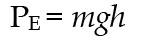
Potential energy is given by:
[1]
Where m is the mass of stored water (kg), g is the gravitational acceleration (m/s2), and h is the height of the water surface above a reference point (usually downstream ground level) (m).
If seepage (piping), overtopping, or a structural breach occurs, this stored potential energy is released and transforms into kinetic energy as water flows downstream. The slurry water then accelerates under gravity, and its energy, KE is now expressed as motion:
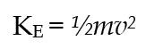
With v as the velocity (m/s).
[2]
This conversion of energy explains why uncontrolled releases from a TSF can be so destructive, namely that stored potential energy is suddenly converted to accelerated moving flows with high erosive and transport capacity.
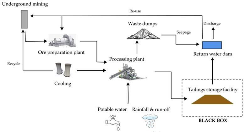
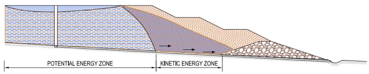
Figure 1—Site-wide mine water balance
Figure 2—TSF energy zones
Tailings storage facility-specific water balance as a standard practice
Potential energy is effectively stored under the pool area. This is called the passive zone. Over time, this volume of tailings increases in density, although it is saturated. From the pool area, a phreatic surface develops and tapers towards the lowest elevation of the dam. This area is where the kinetic energy is developed. This is the active zone. This is where the gravelly tailings material is stored. Void ratio is higher in this area and seepages develop rapidly. Phreatic surfaces can fluctuate significantly in this zone depending on the density and hydraulic conductivity (permeability). Volumetric changes can vary considerably, if not controlled effectively. Volumetric change in soils is linked to density changes that can be controlled by managing the deposition plan efficiently (thin lift deposition), rate of flow (% water: solids ratio), and maintaining effective beach slopes. The stored energy is released and converted into kinetic energy, which is the energy of motion. This is when failure starts to occur as typically occurs with piping failures.
In normal TSF operations, the potential energy of stored water is managed by discharge structures such as decant systems, spillways, seepage drains, and solution trenches that control the conversion of potential to kinetic energy in a safe manner. Failure scenarios develop if systems are not controlled and monitored. The rapid conversion of potential to kinetic energy represents a major risk factor, which is not clearly understood and, therefore, water balance modelling must consider this when evaluating storage levels and freeboard requirements.
Interconnection between degree of saturation, porosity, and void ratio
The degree of saturation (%), porosity (%), and void ratio are interrelated measures of a soil’s void space and water content. Porosity describes the volume of voids with respect to the total volume of the material. Void ratio describes the volume of voids with respect to solids volume. The degree of saturation indicates the fraction of voids filled with water. Together, these factors govern the soil’s water storage, density, and flow characteristics.
As the TSF fills with tailings, the material matrix particles become compressed, and the degree of saturation increases, resulting in a gradual increase in pore water pressure with depth. As water continues to infiltrate, a zone of fully saturated soil develops at the bottom, where all voids are filled with water. The upper surface of this saturated zone is the phreatic surface. The phreatic surface assumes a shape governed by hydraulic gradients, soil permeability, and boundary conditions.
Approach to a TSF-specific water balance
A critical issue in current practices is that water balances often do not explicitly state the current storage volume of water contained within the TSF, i.e., the ‘black box’. If this volume cannot be quantified, it cannot be effectively managed. By adopting a three-staged approach, operators can move from simple checks to comprehensive modelling, thereby visualising how water storage changes over time. This progression allows for proactive
management, ensuring that boundary conditions, such as phreatic surface levels and freeboard requirements, are continuously monitored and that trigger actions, such as halting deposition during extreme rainfall events, can be implemented effectively.
A typical water balance follows a fundamental equation given as: [3]

Where ΔS is the change in storage volume. Inflows include slurry water, precipitation on the TSF surface, surface runoff entering the TSF, and groundwater inflows. Outflows include evaporation from the TSF surface, seepage through the TSF base and walls, recovered water via decant systems and underdrains, and entrapped water within the tailings (Barthe et al., 2018). Refer to Figure 3 for the visual presentation.
Staged approach
Fundamentally, TSF design depends on the in situ ground conditions, and time of construction (given the ever-developing regulations and requirements), and the base treatment (lined or unlined). Furthermore, the choice of TSF will depend on whether it is designed as an upstream, centreline, or downstream construction.
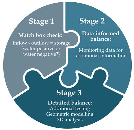
To develop a robust water balance for a TSF, a structured stage system is proposed. This will allow mines to assess the TSF’s storage capacity in an effective realistic approach as follows:
Stage 1: Matchbox approach
This approach begins with a basic ‘matchbox’ check, where inflows and outflows are compared to estimate changes in storage. This is based on current information at hand.
Stage 2: Informed approach
Current data-informed assessment. This incorporates site monitoring information such as slurry flows, rainfall records, evaporation records, pond levels, seepage flows, piezometer measurements, and phreatic levels to refine stage one estimates.
Stage 3: Detailed approach
Detailed analysis using advanced tools such as three-dimensional modelling, survey data, and geotechnical investigations to capture the spatial and temporal behaviour of water within the facility. It involves a detailed process to acquire spatially distributed hydraulic and geotechnical properties, bathymetry, survey grids, and running of 3D models and ensembles, all related to the stability of the facility.
By progressing through these stages, as shown visually in Figure 4, the water balance development evolves from a simple check to a comprehensive management tool, ensuring that both shortterm operations and medium- and long-term risks are effectively addressed. However, prior to following these approaches, it is important that key information is gathered about the site and from its position in the regional context.
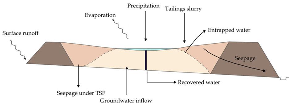
Figure 3—Elements of a water balance of a TSF (after Younger and Wolkersdorfer, 2004)
Tailings storage facility-specific water balance as a standard practice
Basic parameter development and guidance for a three-stage TSF water-balance program
Identifying key parameters controls the focus of the water balance assessment. This will enhance the staged approach to ensure that a robust set of parameters is utilised effectively and realistically. The flow of data development should follow the staged approach described in the aforementioned.
Data gathering
Data is essential at every stage of a water balance model to ensure accuracy and relevance. The data will include typical parameters such as actual type of mine, type of TSF and geometry (pool areas, footprint etc.), climatic inputs (local and regional), rainfall, storm statistics and evaporation/evapotranspiration rates, seepages (both groundwater into the TSF and seepage from the TSF base), deposition tonnages, slurry volumes and densities, specific gravity, dry density, void ratios, porosity, phreatic surfaces, and hydraulic conductivities, to name but a few. Some of the data will be readily available, others will require detailed investigations and analysis. These parameters and their mechanisms are detailed in Table 1.
Planning guidelines
Each stage in the water balance development will depend on the availability of data. Typical timelines for mine management to consider are:
Table 1
Key parameter and data requirements
Category
Examples
Climate and meteorology Rainfall, evaporation, storm statistics.
Operational process data
Pond and geometry
Tailings properties
Boundary/ drainage elements
Instrumentation
Monitoring data
Run-of-mine (ROM) production, slurry density, return water rates.
Pond water level, stage-area-volume relationships, beach topography, bathymetric survey.
Specific gravity, void ratios, degree of saturation, hydraulic conductivity, compressibility/consolidation parameters.
Penstock and seepage drains, liners, permeable horizons, and groundwater levels.
Pond gauges, piezometers, flow meters, weather stations, SCADA/telemetry databases.
Time-series records, survey updates, operational logs.
• Stage 1: Immediate (days → weeks)
• Stage 2: Near term (weeks → 3 months)
• Stage 3: Long term (3–12 months)
In addition to the aforementioned, procurement considerations of at least 3 months can be added to the current timelines.
Recommended practical tolerances
In developing and applying any stage for water balance models for TSFs, it is important to recognise that absolute precision is neither possible nor practical. Instead, tolerances and target levels of accuracy should be defined to guide data collection, model development, and decision-making. These tolerances acknowledge the variability of natural systems (e.g., rainfall, evaporation, and seasonal changes), the uncertainty in material properties (e.g., tailings hydraulic conductivity), and the operational challenges of measuring flows and volumes in real time.
Establishing realistic, accurate targets ensures that models remain both credible, flexible, and operationally useful, providing sufficient confidence for management decisions to be made without creating unrealistic expectations.
The following should be considered as a guideline:
• Rainfall: ±2% – 10% (gauge siting and wind effects).
• Evaporation: ±10% – 15% (seasonal considerations).
• Pond WL: ±0.02 m – 0.05 m (regular surveys).
• Bathymetry depth: ±0.1 m – 0.5 m depending on depth.
• Stage-area-volume relationship: ±5% of volume (depends on survey resolution and frequency).
• Slurry density: ±2% – 5% (continuous or frequent grab samples).
• Tailings geotechnical parameters: order of magnitude (Stage 1) - initial assumptions, narrowing to ±20% (Stage 3)based on targeted lab and field-testing refinement.
• Piezometers: ±0.01 m – 0.05 m.
• Hydraulic conductivity (field): reported as range; ensure order-of-magnitude confidence and quantify spatial variability.
• Seepage/drainage flows: ±10% – 20%.
• Return flow meters: ±2% – 5% reading.
Stage 1: Basic estimates.
Stage 2: Linked to weather data.
Relevant
Stage 3: Extreme event analysis.
Stage 1: ROM tonnage and slurry density.
Stage 2: Regular operational data.
Stage 3: Integrated with water use forecasts.
Stage 1: Simple assumptions, pond levels, areas and volumes.
Stage 2: Monitored pond levels.
Stage 3: Survey-based, installation of piezometers, geometry and 3D modelling.
Stage 1: Generic values and volumes.
Stage 2: Existing data.
Stage 3: Detailed geotechnical investigations, CPTu testing.
Stage 2: Visual inspections and seepage monitoring.
Stage 3: Hydrogeological modelling.
Stage 2: Install and monitor instruments.
Stage 3: Long-term datasets for calibration.
Stage 2: Short-term data records.
Stage 3: Continuous datasets for trend analysis.
Figure 4—Approach to the TSF-specific water balance
Tailings storage facility-specific water balance as a standard practice
Uncertainty handling and realistic notes
Uncertainty is unavoidable in water balance modelling due to variable climatic conditions, measurement errors, and limited data. The aim is not to eliminate uncertainty but to manage it transparently, focusing on the largest contributors and refining estimates as new information becomes available. Pragmatic notes help ensure models remain useful for decision-making despite these limitations. The following considerations are provided:
• Stage 1: Default assumptions - use conservative retention (higher retained porewater) and low recovery to avoid underestimating pond development.
• Stage 2: Progressive reduction of uncertainty - calibration should reduce key uncertainties (pond geometry, return flows, basic seepage).
• Stage 3: Additional testing reduces hydraulic/geotechnical uncertainties and 3D modelling.
• Data quality assurance procedures: Daily credibility checks (mass balance), monthly reconciliation, and correction of instrument errors.
Best practice parameters
For illustrative purposes, the following parameter ranges are considered best practice for a typical platinum TSF in South Africa. These values provide a benchmark for design, monitoring, and operational management. They are not absolute but should be refined as site-specific data becomes available. The best practice parameters are summarised in Table 2.
Worked example
Matchbox check
The first step in developing a water balance is to carry out the simple ‘matchbox’ check as described in the aforementioned sections. The purpose of this first stage is not to deliver precise values, but rather to establish whether inflows and outflows are broadly consistent, and to identify any unexplained changes in storage.
This quick diagnostic tool highlights imbalances that indicate seepage losses, measurement gaps, or operational risks. This will enable the analyst to establish whether the TSF is water-positive or -negative. This foundational step builds confidence and provides a baseline for progressively more detailed assessments in later stages.
Inputs required for the matchbox check
To perform a Stage 1 matchbox check, the following key inputs must be identified. These values are typically available from mine records or can be estimated from site measurements and climatic data. While accuracy at this stage is not critical, using realistic values
Table 2
Best practice parameters
Parameter
Typical Range / target
Rainfall data resolution ± 600 mm/year
Evaporation (pan data) ±1500 mm/year
Slurry density (t/m³) 1.45 – 1.55
Tailings solids SG 2.7 – 3.7
Tailings void ratio (e) 0.7 – 0.9
provides a meaningful first estimate of storage changes. Typical input values for a platinum mine in South Africa include:
• Dry tonnages: 240 kt/month
• Slurry density: 1.5 t/m3
• Specific gravity (SG): 3.3
• Slurry water: 1.2 m3 of water per dry tonne of tailings.
• Direct rainfall: 800 mm/ year.
• Evaporation: 1500 mm/year.
• Areas: Dam 112 Ha, pool 7 Ha
• Dam volume: 22 400 000 m3
• Dam void ratio: 0.9
• Other inputs: Catchment runoff onto TSF.
• Return water: Pumped back to the plant, i.e., penstock, drainage systems.
• Seepage losses: 10% of inflows (estimate) below seepage drainage system.
These values are then combined to check whether inflows and outflows balance within reasonable limits. Any unexplained difference is treated as a change in storage, which highlights whether the facility is gaining or losing water overall. From the above, the following was calculated:
• Total inflows 486 000 m3/month
• Total outflows 127 680 m3/month
• Net storage 358 920 m3/month
It is therefore visible that the TSF is retaining water, and this creates a starting point for further development of Stages 2 and 3 investigations and assessments. To put this into perspective, an Olympic-sized swimming pool has a storage volume of 2 500 m3, this equates to ~ 144 pools being stored in the facility per month.
Development of order of magnitude of water factors for water balances
Through the development of a refined water balance, key order of magnitude of water (OMW) factors can be derived that can aid both mine management and the engineers to apply during the life cycle of the TSF. In the aforementioned example for a Stage 1 estimate, the volume of the TSF divided by the net storage is calculated as 1.36. These factors can then be calculated for each stage of the development of the TSF and ultimately for closure. The industry can then set limits to these factors based on the risk profile of the facility.
Critical water storage levels within a tailings storage facility
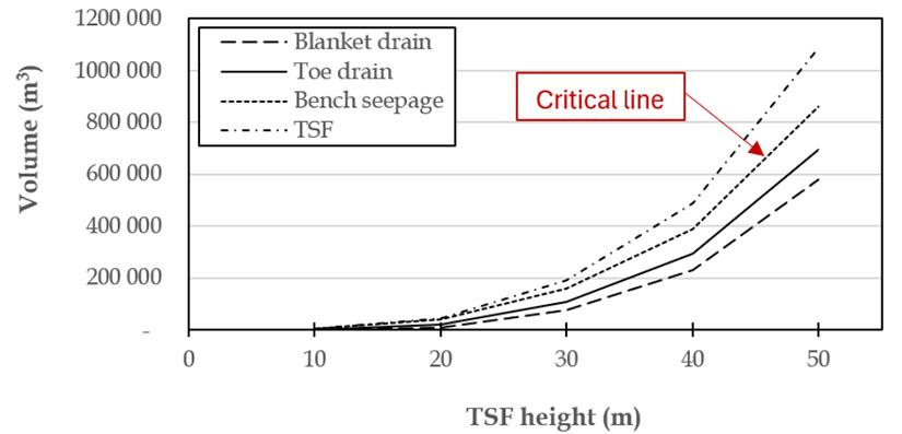
OMW factors will play a significant role in the strategic development of a water balance. A generic illustration is shown in Figure 5, whereby a frustum (circular TSF) is modelled against
Notes / best practice considerations
Site-specific gauges: supplement with regional stations.
Cross-check with station or satellite datasets.
Calibrate with plant data: maintain stability.
Verify per deposit.
Depends on mineralogy and deposition method affects seepage/storage.
Hydraulic conductivity (m/s) 1×10-⁷ – 1×10-⁸ (fine matrix) Use lab/field tests, critical for seepage assessments.
Phreatic surface position ≥ 5 m from downstream crest ≥ 50 m from downstream toe
Water recovery efficiency (%) 60% – 75%
Seepage collection efficiency (%) ≥ 80%
Monitor via piezometers, trigger action if encroaching.
Improve via decant systems, return pumps, or thickened tailings
Design cut-off, toe, blanket, chimney drains, etc.
Tailings storage facility-specific water balance as a standard practice
different heights versus the positioning of seepage drains, i.e., toe and blanket drains. Further, if seepage occurs at a bench, the figure highlights a critical boundary (critical line). The position of seepage drains forms an integral part of the design of TSFs.
With further research, graphs such as nomographs and hydrographs, aided by computer programs, could form an evolutionary approach to understanding the knowledge base of sitespecific TSF water balances.
Compliance regulations
In South Africa, dam safety guidelines are found in the National Water Act (NWA), 1998 (Act No. 36 of 1998) and its regulations regarding the safety of dams. The Act, together with these regulations, stipulate the registration of dams with a safety risk (wall height > 5 m, capacity > 50,000 m³). The dams are classified into Categories I, II, or III, based on size and hazard potential.
The Act further stipulates that owners must obtain a license for construction or modification, and for dams above a certain risk, a registered professional engineer must be appointed to be approved by the Department of Water and Sanitation, Dam Safety Office Directorate (DWS:DSO), i.e., an Approved Professional Person (APP) to conduct safety inspections and ensure compliance with the regulations and their own common law duty of care.
For TSFs, merely using the pool storage volume in safety checks is incorrect, as the interstitial and water contained below the phreatic surface should be considered. This could change the classification of the facility and its risk profile. Currently, it is unknown which volumes to use when registering a TSF at the DSO. In the past, only the pool volume was considered, and now, sometimes the whole capacity of the TSF is considered. Most TSFs have a storage capacity larger than 50 000 m3, but the volume of water inside this structure has not been quantified. This is where the site-specific water balance can fill the gap.
Key findings from a site-specific water balance
Carrying out a site-specific water balance for a TSF is essential for moving beyond assumptions and unknowns. The exercise allows operators to quantify, track, and manage the movement and storage of water, providing several important outcomes:
• Clarity on water storage – It identifies how much water is contained in the facility, which is often poorly understood but is central to both stability and water supply planning.
• Early warning of risks – Discrepancies between inflows and outflows highlight potential seepage, rising phreatic surfaces over time, or unmeasured discharges that may compromise dam safety. It also links phreatic surface dynamics to TSF stability and factor of safety.
• Support for decision-making – Provides a structured basis for operational decisions such as assessing energy balance, reducing pond size, adjusting deposition, change of slope angle, enhancing drainage, or preparing for storm events.
• Improved water efficiency – By quantifying return water and losses, it supports process water recovery and reduces reliance on external water sources.
• Foundation for staged improvement – The simple ‘matchbox’ check develops into progressively more refined monitoring and modelling, creating a path towards continuous improvement.
• Compliance and transparency – Demonstrate responsible management to regulators, communities, and stakeholders by showing that water is being actively monitored and managed.
• Site-specific TSF water balances are to be conducted on a quarterly, biannual, or annual basis depending on life of mine (LOM) status.
• Storing water on TSFs should always be avoided.
The site-specific water balance transforms the TSF from a ‘black box’ into a measurable system. This shift from uncertainty to quantifiable information is critical for safe operation, sustainable water use, and long-term risk reduction.
Conclusion
Water management in mining cannot be fully understood without accounting for the unique role of TSFs. Unlike other site components, TSFs store large and variable volumes of water of which the behaviour changes over time. If left unquantified, this storage represents both an operational unknown and a potential safety risk.
The three-stage water balance approach presented here offers a practical pathway to address this challenge. Starting with a simple ‘matchbox’ check of inflows and outflows, operators can establish a baseline understanding of whether the TSF is gaining or losing water. Building on this, Stage 2 incorporates measured data, such as pond levels, return water flows, and rainfall, refining the balance into a more reliable monitoring tool. Stage 3 then applies advanced modelling and geotechnical inputs to create a dynamic picture of water storage and movement, enabling predictive management.
The key message is that water balances should not stop at the site scale. By applying a TSF-specific focus, operators gain clearer insight into stored water volumes, improve water recovery, enhance dam safety, and align with al standards such as the GISTM (ICMM, 2020). Ultimately, adopting TSF-specific water balances transforms the facility from a ‘black box’ into a managed system (termed a ‘blue box’), reducing risks while supporting sustainable and responsible water use.
Acknowledgements
The authors would like to thank SRK Consulting participants who assisted with the compilation of this paper.
References
Barthe, P., Eder, P., Savin, H. G. M., Orveillon, G., Garbarino, E. 2018. Best available techniques (BAT) reference document for the management of waste from extractive industries – In accordance with Directive 2006/21/EC, Publications Office.
https://data.europa.eu/doi/10.2760/35297
Global Industry Standard on Tailings Management. 2020. International Council on Mining and Metals (ICMM), United Nations Environment Programme (UNEP), Principles for Responsible Investment (PRI). Available at: https://globaltailingsreview.org/global-industry-standard/ National Water Act (NWA). 1998. (Act No. 36 of 1998). Pretoria Younger, P., Wolkersdorfer, C. 2004. Mining Impacts on the Fresh Water Environment: Technical and Managerial Guidelines for Catchment Scale Management, Mine Water and the Environment, 23, s2-s80. DOI:10.1007/s10230-004-0028-0 u
Affiliation:
1 SRK Consulting, Johannesburg, South Africa
Correspondence to: M. Brink
Email: MBrink@srk.co.za
Dates:
Received: 10 February. 2026
Published: April 2026
How to cite:
Brink, M., Mtshali, C.R., Howell, G.C., Macfarlane, N.G. 2026. Collaborative accountability: Empowering roles in tailings storage facilities governance and risk management. Journal of the Southern African Institute of Mining and Metallurgy, vol. 126, no. 4, pp. 227–234
DOI ID:
https://doi.org/10.17159/2411-9717/973/2026
ORCiD: M. Brink
https://orcid.org/0009-0006-9382-2696
G.C. Howell
https://orcid.org/0009-0009-7739-8946
Collaborative accountability: Empowering roles in tailings storage facilities governance and risk management
by M. Brink1, C.R. Mtshali1, G.C. Howell1, N.G. Macfarlane1
Abstract
Effective governance of tailings storage facilities hinges on adherence to international standards like the Global Industry Standard on Tailings Management, which promotes safety, sustainability, and ethical accountability in mining. However, governance is not just about assigning titles; it demands a deep, active engagement with the responsibilities those roles entail.
This paper explores the philosophical risks of role misalignment in tailings storage facilities governance. When individuals treat roles as symbolic rather than functional, they risk undermining the intent of the entire framework. Titles alone do not ensure accountability; it is the embodiment of responsibility that matters. Misalignment leads to poor communication, blurred decision-making, and a lack of long-term risk awareness.
Central to this discussion are the roles of the Engineer of Record, Responsible Tailings Facility Engineer, and Accountable Executive, as defined in Principle 9 of the Global Industry Standard on Tailings Management. The paper examines how these roles interconnect and how the Accountable Executive must empower the Engineer of Record, not just formally, but in a way that enables meaningful oversight. The concept of ‘empowerment’ is unpacked to emphasise its practical and ethical dimensions.
Additionally, the paper explores the ‘as low as reasonably practicable’ risk principle and its relevance to tailings storage facilities governance. The low as reasonably practicable principle is not just a technical guideline; it reflects a commitment to minimising risk through informed, ethical decision-making. The roles of the Engineer of Record, Responsible Tailings Facility Engineer, and Accountable Executive must align with this principle to ensure that risk management is both effective and morally sound.
Ultimately, this paper critiques current governance practices and calls for a shift toward genuine engagement. It argues that holding a role means more than having a title; it requires understanding, commitment, and ethical accountability. By rethinking how roles are defined and enacted, the mining industry can better manage systemic risks and foster a culture of responsible stewardship.
Keywords
Tailings Storage Facilities (TSFs), GISTM governance, Collaborative accountability Engineer of Record (EOR), Risk management, ALARP principle and Role misalignment
This paper is based on a presentation given at the Tailings 2026 - Where To Now? Conference, 3-4 March 2026, Indaba Hotel, Spa and Conference Centre, Fourways Introduction
Tailings storage facilities (TSF) are critical components of mining operations, designed to contain the residual by-products of mineral extraction, often a mixture of finely ground rock, water, and potentially hazardous substances such as heavy metals or process chemicals. If not managed responsibly, TSFs pose significant risks to human health, ecosystems, and infrastructure. Catastrophic failures can result in widespread environmental damage, loss of life, and long-term socio-economic disruption. Recognising these risks, the Global Industry Standard on Tailings Management (GISTM) advocates for a comprehensive, lifecycle-based approach to TSF management, integrating sound engineering practices with robust governance structures. At the heart of this governance framework is a triad of roles: the Accountable Executive (AE), the Responsible Tailings Facility Engineer (RTFE), and the Engineer of Record (EOR). These roles form a collaborative triangle, each with distinct but interrelated responsibilities, authorities, and competencies. The structure is designed to function through collaborative accountability, where effective TSF management depends not only on individual expertise, but on the alignment and interaction of these roles.
This paper explores the philosophical and practical risks that arise when this alignment breaks down. Role misalignment (where individuals hold titles without fully enacting the responsibilities they imply) can lead to gaps in oversight, blurred decision-making, and ethical ambiguity. It can leave
Collaborative accountability: Empowering roles in tailings storage facilities governance and risk management
individuals exposed to liability and, more critically, result in failures of execution when the appropriate party is either not adequately empowered or does not take ownership of essential tasks. The paper critiques the mining industry’s current ability to embody the tenets of the GISTM as intended. It argues that titles alone do not ensure accountability; rather, it is the meaningful enactment of responsibility that safeguards TSF integrity. It further considers the ‘as low as reasonably practicable’ (ALARP) risk principle as a moral and practical benchmark for risk management, arguing that role alignment (particularly in how each governance actor interprets and applies ALARP) is fundamental to ensuring that TSF management is not only technically effective, but ethically sound. When the EOR, RTFE, and AE operate in concert, with clearly defined responsibilities and mutual empowerment, the governance structure functions as intended, i.e., to reduce risk and uphold the GISTM’s goal of zero harm.
Governance framework for TSFs
Overview of TSF governance in terms of GISTM
The Global Industry Standard on Tailings Management (GISTM), released in 2020 by the Global Tailings Review (GTR), defines a governance model designed to achieve ‘zero harm to people and the environment’ through clearly articulated accountability, responsibility, and competency frameworks (GTR, 2020). It replaces legacy ambiguity in tailings oversight, such as that observed under SANS 10286, with a globally consistent structure centred on four key appointments, those being the Accountable Executive (AE), Responsible Tailings Facility Engineer (RTFE), Engineer of Record (EOR), and the Independent Tailings Review Board (ITRB). This framework aligns corporate governance with engineering practice by ensuring that competent professionals make technical decisions and that ultimate accountability resides at the highest corporate level. As outlined by MacRobert et al. (2022), the AE ensures that management structures and resources exist, the RTFE manages facility-level risk, the EOR guarantees technical integrity, and the ITRB provides independent assurance without decisionmaking authority. Together, these roles form the backbone of GISTM-aligned governance systems.
Roles in TSF governance
The GISTM is built on the recognition that safe tailings management is not solely a technical exercise but a governance discipline requiring the alignment of authority, accountability, and competence throughout an organisation. Before the publication of
the GISTM, governance arrangements for tailings facilities were often fragmented and inconsistent, creating uncertainty over who ultimately bore responsibility for safety. The GISTM was developed to remove this ambiguity by defining a transparent management hierarchy that ensures critical decisions are made by qualified professionals while keeping accountability anchored at the highest corporate level (GTR, 2020).
In the South African context, shaped historically by SANS 10286, Code of Practice, Mine Residue (2013), the use of terms such as manager, operator, and professional engineer was frequently inconsistent, leading to blurred lines of responsibility.
MacRobert et al. (2022) highlighted that this structural ambiguity allowed operational and design responsibilities to overlap without clear accountability, which could compromise facility safety.
The GISTM resolves this by prescribing four explicit appointments, each with clearly defined authority and responsibility:
➤ The AE, who embodies corporate accountability and ensures governance structures, competencies, and resourcing are in place.
➤ The RTFE, who manages day-to-day operational integrity and risk control at the facility level.
➤ The EOR, who assures technical adequacy, design conformance, and lifecycle safety.
➤ The ITRB, which provides objective, periodic review and external assurance of safety drivers.
These appointments form the foundation of the GISTM accountability framework, addressing one of the key lessons identified from major tailings failures worldwide—namely, that a lack of clear ownership and communication was a recurrent causal factor (GTR, 2020; MacRobert et al., 2022). By defining who is responsible for what, and how authority flows between roles, the GISTM promotes a culture in which risk ownership is transparent, decisions are traceable, and safety is prioritised above production (Ruiz et al., 2022).
The four key roles are summarised in Table 1, along with their principal functions and spheres of accountability.
Together, these appointments create an integrated triangle of accountability that links strategic authority, operational responsibility, and technical assurance. Each role is distinct, yet interdependent; the effectiveness of this framework relies not only on the appointment of competent individuals but on their empowerment to act within clearly defined boundaries of authority, an issue explored further in the next section.
GISTM roles together with principal functions and spheres of accountability
Role
Accountable Executive (AE)
Responsible Tailings
Facility Engineer (RTFE)
Engineer of Record (EOR)
Independent Tailings Review Board (ITRB)
Appointed by Core functions
CEO or Board of Directors
Mine Manager with AE input
Mine Manager with AE input
Operation with AE input
Ensures governance structures, competent staffing, and financial resources are in place; approves risk-acceptance levels; appoints the ITRB.
Accountable for facility integrity; coordinates between AE, EOR, and operations; defines scope and budget for technical work.
Designs, reviews, and approves all facility works; conducts inspections and performance evaluations; guides construction, operation, and closure criteria.
Provides an independent review of safety drivers and risk trends throughout the facility lifecycle.
Note: Table compiled by the authors based on GTR (2020), MacRobert et al. (2022), and Ruiz et al. (2022)
Accountability focus
Corporate oversight and strategic risk ownership.
Operational execution and risk control.
Technical assurance and design conformance.
External assurance and continuous improvement.
Table 1
Collaborative accountability: Empowering roles in tailings storage facilities governance and risk management
Role,
responsibilities, and interdependencies:
The governance triangle
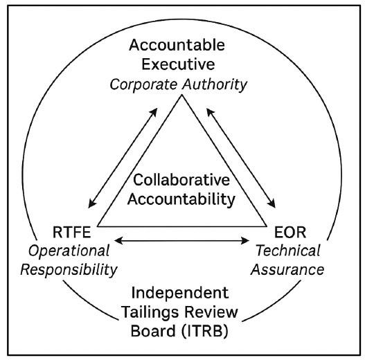
The GISTM recognises that the safe management of a TSF depends not only on sound engineering but also on a clear and balanced governance structure. At the centre of this structure is a three-way relationship between the AE, the RTFE, and the EOR. MacRobert et al. (2022) describe the AE–RTFE–EOR relationship as a mutually reinforcing structure, rather than a hierarchy. These roles form what has become known as the ‘triangle of accountability’ or governance triangle (MacRobert et al., 2022).
Each vertex of the triangle represents a different dimension of governance:
➤ Corporate authority (AE);
➤ Operational responsibility (RTFE);
➤ Technical assurance (EOR).
For the triangle to function effectively, these three dimensions must operate in dynamic equilibrium, supported by communication, trust, and mutual empowerment. The triangle works only when each side supports the others; if one weakens, the whole system becomes unstable. The GISTM’s design assumes that no single role alone can ensure safety; only the interaction between them can maintain it.
This schematic, shown in Figure 1, illustrates the interdependent relationship between the three core governance roles defined by the GISTM: The AE, RTFE, and EOR. Each vertex of the triangle represents a distinct but complementary sphere of accountability.
At the top of the triangle sits the AE, usually a senior company leader with the authority to commit resources and make policy decisions. The AE is ultimately responsible for embedding tailings safety into the company’s wider risk and governance framework. This means ensuring that the right people are appointed, that they are competent and empowered, and that sufficient funds and systems are in place to manage risk effectively. GISTM Principle 2 explicitly states that ultimate accountability for TSF safety rests with the company’s highest governing body (GTR, 2020). In practical terms, the AE’s responsibilities include:
➤ Approving risk acceptance criteria and tolerances.
➤ Ensuring a competent RTFE and EOR are appointed and empowered.
➤ Maintaining direct oversight through periodic reviews and board-level reporting.
The AE must therefore translate corporate governance into technical action by enabling and resourcing the RTFE and EOR. When the AE fails to empower these roles, risk migrates downward into operational and technical layers without adequate authority to
mitigate it (MacRobert et al., 2022). The AE’s ability to resource and empower the RTFE and EOR is what gives the governance system strength and credibility.
The RTFE sits at the operational base of the triangle. This is the person directly responsible for the day-to-day integrity of the facility, making sure that deposition, water management, instrumentation, and maintenance all align with design intent and company policy. The RTFE acts as the main link between the AE and the EOR, translating corporate expectations into practical action on site. According to the GISTM, the RTFE is accountable for the integrity of one or more named facilities, acting as the custodian of site-level implementation of the tailings management system (GTR, 2020). This means that the RTFE must have enough authority and time to focus solely on tailings safety. The RTFE’s functions include:
➤ Overseeing day-to-day operations of the TSF, including deposition, water balance, and instrumentation.
➤ Coordinating risk communication between operations, the EOR, and corporate management.
➤ Ensuring that design recommendations are implemented as intended.
➤ Maintaining awareness of the facility’s performance and compliance status.
MacRobert et al. (2022) observed that, in South African practice, the RTFE role is often conflated with other managerial duties (e.g., metallurgical or plant management), which dilutes its focus and creates potential governance gaps. This can create divided priorities and blurred accountability. The RTFE should therefore be a dedicated, technically competent individual with authority to act, sufficient resources, and direct access to both the AE and the EOR.
The EOR is the technical cornerstone of the triangle. This role carries a professional responsibility, with the primary mandate to ensure that the facility is designed, constructed, operated, and closed in accordance with the design intent and applicable standards. They carry professional and ethical accountability for the technical adequacy of the facility and for verifying that its performance remains within acceptable limits (MacRobert et al., 2022). The EOR collaborates closely with the RTFE to interpret performance data, identify deviations, and recommend remedial actions.
In line with GISTM Principle 9, the EOR’s professional judgment must take precedence over commercial or production pressures (GTR, 2020). However, this is only achievable when the AE formally empowers the EOR to make safety-critical recommendations without interference. Ruiz et al. (2022) demonstrated that when the AE grants the EOR direct access to decision-making channels, rather than reporting through multiple management layers, tailings governance systems mature faster, achieve more consistent safety outcomes, and adopt best practices more effectively.
Although not part of the internal triangle, the Independent Tailings Review Board (ITRB) provides an essential external perspective. Its role is to review both the technical condition of the facility and the effectiveness of the governance relationships themselves. As shown by Ruiz et al. (2022), active and regular engagement with an ITRB strengthens internal accountability and promotes a culture of continuous improvement rather than reactive compliance.
Figure 1—Interdependent relationship between the three core governance roles: The AE, RTFE, and EOR
Collaborative accountability: Empowering roles in tailings storage facilities governance and risk management
The Governance Triangle is not a chain of command but a system of shared accountability and constant feedback. Information must circulate freely among all three parties. The AE relies on the RTFE and EOR for an honest assessment of risk, the RTFE relies on the EOR for technical direction, and the EOR relies on the AE for the mandate and resources to act. If communication fails or one role is under-resourced, responsibility becomes fragmented, and decisions can be delayed or diluted. This breakdown in collaboration has been identified as a recurring weakness in past TSF failures (MacRobert et al., 2022).
A balanced triangle is characterised by:
➤ clear reporting lines and defined escalation procedures;
➤ regular three-way meetings and transparent documentation;
➤ mutual respect for each role’s boundaries and expertise;
➤ a shared understanding that risk accountability is collective, not isolated.
When the triangle is functioning well, decisions are transparent, recommendations are implemented quickly, and each party understands its limits and obligations. When it is not, the structure becomes top-heavy, dominated by production or cost pressures, and the engineers who carry technical risk are left without the authority to prevent unsafe practices.
Philosophical exploration of responsibility
What does it mean to hold a role in TSF governance?
As highlighted in this paper, the GISTM introduces a structured framework of role-based accountability aimed at enhancing the safety, integrity, and transparency of tailings facilities. But what does it truly mean to hold a role in TSF governance? Appointment to a defined role, such as AE, EOR or RTFE, is intended to represent a formal entrustment of ethical, technical, and operational responsibility. Philosophically, however, the concept of ‘holding a role’ extends beyond procedural designation. It implies participation in a social contract of stewardship, where professional identity is shaped by the duty to safeguard human life, environmental integrity, and public trust.
Yet, the embodiment of these roles in current industry practice reveals a persistent tension between the conceptual ideals embedded in governance standards and the pragmatic realities of role execution. Research in engineering ethics and governance shows that while roles are formally assigned, their enactment is often shaped by organisational constraints, cultural norms, resource scarcity, and ambiguous accountability structures (MacRobert et al., 2022). Johnson (2017) argues that accountability must be understood as a relational practice, shaped through interactions and shared norms, not merely an isolated moral obligation. In the context of tailings governance, this means that the ethical weight of a role is not automatically realised through appointment – it must be actively cultivated through institutional support, professional competence, and a culture of ethical responsibility.
Moreover, the Southern African mining context presents unique challenges, including a limited pool of qualified professionals and competing pressures between regulatory compliance and operational efficiency. This often leads to symbolic compliance, where roles are filled to meet external expectations but lack the depth of engagement required for meaningful accountability (MacRobert et al., 2022). As such, interrogating the philosophical nature of holding a role in TSF governance reveals a critical gap between the aspirational framework of the GISTM and the lived realities of its implementation.
Symbolic versus functional roles
Symbolic roles refer to positions that are formally assigned within an organisation or governance framework but may lack substantive authority, engagement, or impact. These roles often serve to signal compliance, legitimacy or alignment with external expectations (such as regulatory standards or public scrutiny), without necessarily influencing decision-making or operational outcomes.
In contrast, functional roles are actively performed and embedded within the organisational processes. They involve real decision-making power, technical competence, and ethical responsibility. Functional role holders engage with the complexities of their duties and are supported by institutional structures that enable accountability and oversight.
Westphal and Park (2020) highlight a pervasive pattern in organisations where formal governance structures are often decoupled from actual practices, creating a disconnection between appearance and reality. This misalignment fosters symbolic management, where compliance and oversight mechanisms exist more for display than for substantive effect, ultimately undermining the integrity of governance systems. In the context of tailings management and the GISTM, this decoupling may occur when roles such as the EOR or RTFE are appointed to satisfy the external standards for compliance purposes but lack the necessary institutional support or clarity required for meaningful execution of their duties.
This distinction between symbolic and functional roles sets the stage for a deeper philosophical inquiry into the nature of responsibility in governance frameworks, particularly in high-risk contexts like TSF management, where the consequences of role failure can be profound.
Responsibility and accountability in TSF governance Responsibility, accountability, and authority are foundational, yet distinct concepts in governance, each contributing to the clarity and effectiveness of role-based systems. The ICMM Tailings Management Good Practice Guide (2025) offers precise definitions:
➤ Responsibility is the obligation to perform a task in accordance with defined expectations, with consequences if those expectations are not met.
➤ Accountability is the answerability for one’s own performance and that of others whose work one directs, and it cannot be delegated.
➤ Authority is the power to make decisions and assign or delegate responsibilities appropriately.
These distinctions are not merely semantic but are key to establishing clarity in governance structures and ensuring ethical and effective decision-making.
Responsibility refers to the duty or obligation to perform assigned tasks in accordance with defined expectations. It is typically linked to a role or position and flows upward in organisational hierarchies. In TSF governance, responsibility is both technical and moral. For example, an RTFE is tasked with ensuring that operational practices conform to design specifications and safety protocols. This responsibility includes anticipating risks and making informed decisions that protect human and environmental well-being.
Accountability is the requirement to answer for one’s actions and decisions, including those delegated to others. Unlike responsibility, accountability cannot be delegated – it remains with the individual or entity that holds it. The ICMM Good Practice Guide emphasises that individuals with accountability must be
Collaborative accountability: Empowering roles in tailings storage facilities governance and risk management
clearly identified and supported by governance structures that enable oversight and ethical scrutiny (ICMM, 2025). In practice, the AE in a mining company is answerable for the safety of tailings facilities, even if operational tasks are delegated to engineers or contractors. The role requires not only technical understanding but also ethical leadership and the ability to respond to failures or emergencies.
Authority is the legitimate power to make decisions, assign responsibilities, and allocate resources. It flows downward in organisational hierarchies and is essential for enabling individuals to act on their responsibilities. Without appropriate authority, responsibility and accountability become symbolic rather than functional.
For example, if an RTFE is responsible for implementing safety protocols but lacks the authority to halt operations or request additional resources, their role is undermined. The ICMM Good Practice Guide stresses that individuals with responsibility and accountability must also have commensurate authority to act effectively (ICMM, 2025). This alignment is crucial for ethical governance as it ensures those who are expected to act are empowered to do so.
Strengthening the Governance Triangle through collaborative accountability
Effective tailings governance relies not only on the clarity of individual roles but on the alignment and interaction of three foundational elements: Responsibility, accountability, and authority. When these elements are misaligned, such as when individuals are held accountable without authority, or given responsibility without support, governance systems become vulnerable to failure. This is particularly dangerous in TSF management, where unclear roles can lead to delayed decisions, overlooked risks, and catastrophic outcomes.
The Governance Triangle – comprising the AE, RTFE, and EOR, as described already in this paper, provides a structured and balanced framework for distributing the core governance
Table 2
Responsibilities, authorities, and accountabilities of key role players
Accountable Executive (AE)
Responsible Tailings Facility Engineer (RTFE)
Engineer of Record (EOR)
Table 3
Embed tailings safety into corporate governance; appoint and empower RTFE and EOR; approve risk tolerances.
Oversee day-to-day TSF operations; ensure compliance with design intent and safety protocols.
Ensure design, construction, operation, and closure meet technical standards and design intent.
Role differentiation and interdependencies Role
Engineer of Record (EOR)
attributes of responsibility, accountability, and authority across distinct yet interdependent roles. By assigning each role a specific domain – corporate oversight (AE), operational execution (RTFE), and technical assurance (EOR) – the triangle ensures that no single individual bears disproportionate governance burden. This separation of functions allows each role to operate with clarity and autonomy within its sphere, while still contributing to a unified safety and risk management strategy. More importantly, the distribution of governance functions enables collaborative accountability, where each role supports and reinforces the others through shared responsibilities and open communication.
Table 2 outlines the specific responsibilities, authorities, and accountabilities of each role, illustrating how their distinct functions contribute to a cohesive governance system.
Each role must be empowered to act within its domain. For example, the AE must have the authority to allocate resources and approve risk thresholds, while the RTFE must be able to halt operations if safety is compromised. The EOR must be able to issue independent technical recommendations without interference from production pressures (GISTM, 2020; Ruiz et al., 2022).
Rather that functioning hierarchically, these roles operate in complementary alignment, as mentioned before. By enabling and deliberately engaging with each other through continuous communication, an environment of mutual respect and a shared commitment to safety will be fostered. As shown in Table 3, each role has a unique focus but overlaps in decision-making and risk management, which is essential for integrated and effective governance.
The triangle’s resilience lies in its ability to enact and embody individual responsibilities in concert. When one role is underresourced or lacks authority, the triangle becomes unstable. For instance, if the EOR is not empowered to escalate safety concerns directly to the AE, technical risks may go unaddressed. Similarly, if the RTFEs are burdened with unrelated managerial duties, their focus on tailings safety may be diluted (MacRobert et al., 2022).
Strategic decision-making; resource allocation; policy setting.
Operational authority to implement safety measures and escalate risks.
Authority to make safetycritical recommendations; access to decision-makers.
Ultimate accountability for TSF safety and governance outcomes.
Accountable for sitelevel implementation and performance.
Professional accountability for technical adequacy and conformance.
Collaborative accountability: Empowering roles in tailings storage facilities governance and risk management
Practical implications of role misalignment
Defining role misalignment
The governance framework established by the GISTM depends on a deliberate balance of authority, responsibility, and technical competence among the AE, RTFE, and EOR. When roles are clearly defined and aligned, decision-making is transparent, communication remains open, and safety is prioritised through early identification and timely mitigation of risk. When alignment deteriorates, collaborative accountability fractures, resulting not only in inconsistent decisions and weak communication, but also in delayed interventions, which can materially increase the likelihood of failure.
Role misalignment arises when the distribution of responsibility, authority, decision-making, timing or accountability among these roles becomes unclear, overlapping, or inconsistent with the intent of governance frameworks such as the GISTM. It often stems from ambiguous reporting lines, inadequate empowerment, misplaced delegation, or escalation pathways that introduce delay at critical moments. In this context, misalignment is not only about who is responsible and what they are responsible for, but also when decisions are made and how quickly action can be taken. Fundamentally, misalignment occurs when the what (responsibilities), who (role holders), how (authority to act), and when (timeliness of intervention) are not coherently aligned. This breakdown undermines the principle of collaborative accountability and typically manifests as communication barriers, deferred decisions, and risk controls being implemented too late to prevent escalation.
The manifestations of role misalignment vary with organisational structure, technical capacity, and communication practices. Table 4 summarises recurring industry examples illustrating how unclear authority, unsuitable appointments, or filtered communication compromise the governance intent of the GISTM and erode accountability and risk visibility.
These examples demonstrate that misalignment rarely appears as a single failure but as a systemic weakness across the governance structure. When interfaces between the AE, EOR, and RTFE are not clearly delineated or respected, accountability diffuses and risk
Table 4
Examples of role misalignment in TSF governance
Type of misalignment
Ambiguous accountability between the AE and EOR.
RTFE appointed from a non-technical background.
Delegation without empowerment.
Communication filtering through management layers.
Description
The AE retains overall accountability for TSF performance but fails to empower the EOR to challenge design or operational decisions, resulting in blurred responsibility.
The appointment of an RTFE lacking geotechnical or structural expertise limits the understanding of stability risks and weakens technical oversight.
Responsibilities are delegated without sufficient authority, limiting the ability to enforce risk controls or initiate timely interventions.
Risk information is diluted or delayed when filtered through hierarchical management before reaching accountable decision-makers.
ownership blurs. Consequently, organisational safeguards, such as oversight committees or design reviews, may fail to detect early signs of technical or behavioural drift. Respected engineers within the South African industry have consistently raised concerns about the potential risks posed by breakdowns in governance – warning that failures often stem not from isolated errors, but from persistent structural and behavioural misalignments (MacRobert et al., 2022).
Simultaneously, individuals occupying these roles face disproportionate personal liability for outcomes they cannot fully influence. This duality, where institutional risk increases while individual accountability intensifies, highlights the need for clear authority pathways and empowered technical roles. The following subsection explores these vulnerabilities in greater depth, exploring how each role carries distinct organisational and individual risks within the governance hierarchy.
Risks and challenges in role misalignment
Role misalignment generates complex risks that extend beyond operational inefficiency to threaten governance integrity. When authority and accountability lose clarity, both organisations and individuals are exposed to uneven and amplified risks within the AE–RTFE–EOR structure.
The Accountable Executive (AE) holds ultimate corporate responsibility for ensuring that governance systems are effective, adequately resourced, and supported by sound oversight mechanisms. This role anchors the organisation’s legal and reputational standing. When safety measures are poorly enforced or professional advice is ignored, consequences may include regulatory penalties, shareholder litigation, and a loss of stakeholder confidence. On a personal level, the AE faces ethical and, in some jurisdictions, legal exposure stemming from uninformed or technically unsound decision-making. The AE therefore operates within a delicate balance where accountability may exceed technical competence, creating governance gaps that can compromise the quality of decisions made at the highest level.
The Responsible Tailings Facility Engineer (RTFE) functions at the interface between operational delivery and technical assurance. Organisationally, lapses in compliance or inadequate control
Illustrative example
The AE delegates key design changes to operations management without consulting the EOR, who is then held responsible for a facility they did not meaningfully influence.
The RTFE, drawn from a metallurgical background, prioritises production continuity over embankment stability, disconnecting operational performance from safety assurance.
The RTFE delegates inspection oversight to a junior engineer who identifies safety concerns but lacks the authority to implement corrective measures. AND
Relying on the EOR to maintain technical oversight without a formal contractual appointment to perform the associated duties.
A slope-stability concern raised by the EOR is softened during internal reporting to avoid production disruption, delaying mitigation action.
Collaborative accountability: Empowering roles in tailings storage facilities governance and risk management
within the RTFE’s remit can jeopardise both facility integrity and production continuity. The risk to the organisation increases when the RTFE lacks the authority and/or the ``expertise to enforce geotechnical controls (for example), particularly in environments driven by production targets. Individually, the RTFE faces the challenge of balancing operational efficiency with safety obligations. This duality can foster divided loyalties, where production pressures overshadow risk management responsibilities. Delegating oversight without verification, or disregarding the EOR’s technical guidance, can constitute professional negligence and expose the RTFE to disciplinary or legal consequences.
The Engineer of Record (EOR) carries the highest level of technical and ethical responsibility within the governance structure. At an organisational level, design errors, misinterpretation of monitoring data, or inadequate performance evaluation can lead to significant financial loss, environmental harm, and reputational damage. The risk is compounded when a single EOR is assigned to multiple facilities, reducing continuity of institutional knowledge and increasing systemic vulnerability. Individually, the EOR bears substantial personal liability. Professional registration obliges the EOR to act independently, uphold ethical standards, and prioritise public safety. Yet, when management interference, incomplete and/or flawed and erroneous data sets, or commercial pressures compromise professional judgement, this independence can erode, turning technical challenges into ethical dilemmas and legal exposure.
Collectively, these vulnerabilities show that misalignment undermines not just operations but the ethical foundations of governance. A particularly critical outcome occurs when the EOR is not empowered by the AE to exercise independent technical judgment, an issue explored in the following.
Implications of EOR disempowerment in relation to GISTM Principle 9
When the AE does not adequately empower the EOR, the consequences extend beyond technical oversight and undermine the intent of GISTM Principle 9. This principle requires that qualified professionals inform all decisions and that the safety of people and the environment take precedence over production and cost considerations. EOR disempowerment (through scope restrictions, delayed approvals, erroneous or misleading data, or withheld resources) transfers organisational risk to the individual engineer.
Production pressures that defer maintenance or exceed design limits also erode the risk principle, as low as reasonably practicable (ALARP), weakening the foundation of risk-based decisionmaking. Professionally, failure to escalate or withdraw endorsement may constitute negligence and ethically, it represents a breach of duty of care. Furthermore, legally, it exposes the EOR to shared liability with the owner’s management.
Disempowerment replaces collaborative accountability with top-down control driven by production priorities. As noted by MacRobert et al. (2022), these imbalances are increasingly evident in organisations where formal role appointments have progressed more rapidly than the systems and authority structures that are required to support genuine professional empowerment.
Preventing these outcomes requires formal safeguards. The EOR must have: Authority to suspend unsafe operations, direct access to the AE and board, transparent escalation procedures, and protection for technical dissent. These measures preserve
professional independence and uphold the GISTM’s intent.
Ultimately, the EOR’s duty is to protect life, the environment, and the public interest. Silence in the face of risk is an ethical failure. Genuine empowerment under Principle 9 ensures that safety decisions remain within the domain of qualified professionals and that risk is judged consistently across the governance framework.
ALARP principle and its influence on decision-making
The ALARP risk principle requires that all reasonable measures be taken to reduce risk until further mitigation becomes grossly disproportionate to the benefit gained. Its application varies with how each role interprets ‘reasonable’ and ‘practicable.’
For the AE, ALARP is often viewed through a corporate lens that balances safety against financial and production objectives. This can narrow the definition of ‘reasonably practicable’ when short-term economic priorities dominate. The RTFE, operating at an operational level, tends to apply ALARP reactively (focusing on compliance and continuity rather than proactive risk reduction), especially under production pressure. By contrast, the EOR interprets ALARP as an ethical and professional duty to minimise risk to life and the environment, independent of commercial influence. This aligns with GISTM Principle 9 but relies on genuine empowerment to be upheld in practice.
These differing interpretations create uneven applications of ALARP across the governance framework. While all parties may claim adherence, their thresholds for acceptable risk vary, often reflecting organisational hierarchy rather than objective assessment. Achieving consistency requires shared risk criteria, transparent justification, and alignment of accountability so that ALARP remains a tool of safety assurance, not of convenience.
Appropriate appointment of the RTFE and its influence on governance integrity
Consistent application of ALARP also depends on the technical suitability of the RTFE, who is the operational custodian of risk. Under GISTM, the RTFE must uphold facility integrity through technically informed oversight (ICMM, 2020; ICOLD, 2022). However, many operations appoint metallurgists or production managers based on seniority rather than technical alignment (MacRobert et al., 2022). While these individuals bring process expertise, they may lack the geotechnical competence needed to assess embankment behaviour or recognise early instability, for example, often prioritising production over safety (Blight, 2010; Morgenstern, 2018).
Conversely, appointing a geotechnical or tailings engineer as RTFE aligns with the GISTM’s emphasis on informed, risk-based decisions (Robertson, 2021). Such individuals can better interpret performance data, challenge operational pressures, and collaborate effectively with the EOR (Azam, Li, 2010). Competence-based appointments enhance governance credibility, support consistent ALARP application, and reinforce collaborative accountability (ICOLD, 2022; Morgenstern et al., 2015).
Effective TSF governance relies not only on defined responsibilities but on empowerment, competence, and integration. When authority and accountability diverge—through disempowered EORs, operationally constrained RTFEs, or inconsistent ALARP interpretation—the intent of the GISTM is diluted. The next section examines these broader systemic factors, analysing how current organisational culture and leadership behaviours serve to reinforce misalignment and limit the practical realisation of GISTM principles.
Collaborative accountability: Empowering roles in tailings storage facilities governance and risk management
Critique of current TSF governance structure
The GISTM provides a robust framework for governance and accountability in TSF management. It has clarified roles, improved transparency, and raised the visibility of tailings risks at the executive level. However, consistent implementation remains uneven, limited by hierarchical structures, resource disparities, and differing interpretations of accountability within the AE–RTFE–EOR framework.
While the GISTM has fostered a shared language of responsibility and embedded tailings risk within corporate decision-making, governance often remains procedural rather than transformative, strong in documentation but weak in behavioural change. This gap between policy and practice undermines the intent of the standard and sustains fragmented accountability.
Advancing governance maturity requires a shift from compliance to role embodiment. The AE, RTFE, and EOR must act as interdependent peers within a system of shared accountability, supported by both structural mechanisms and a culture of ethical engagement. Achieving this alignment demands more than formal compliance; it calls for continuous learning, professional courage, and empowerment across all levels of decision-making.
Although many organisations have achieved compliance milestones, few have internalised the GISTM’s principles into everyday governance, that is, procedural comfort risks replacing active stewardship. Sustained improvement depends on reinforcing professional accountability, clarifying interfaces, and maintaining ethical vigilance against production-driven decisions.
Implementing the GISTM also requires significant investment. Recruiting and retaining qualified AEs, RTFEs, and EORs, supported by capable teams, imposes costs that challenge smaller or lower-margin operations. Yet, underinvestment in governance capacity presents far greater long-term risk. Competent, empowered professionals remain the most effective safeguard against technical failure and reputational loss.
Despite its emphasis on defined roles, the current governance structure provides few mechanisms for genuine collaboration. The AE–RTFE–EOR relationship often functions through reporting lines rather than active dialogue, weakening both technical input and shared ownership of risk. Strengthening this ‘governance triangle’ requires structured communication pathways, joint risk reviews, and transparent escalation processes that allow unfiltered technical concerns to reach the executive level. Building mutual respect and accountability can transform the framework from a compliance hierarchy into a learning-oriented system capable of managing evolving risks.
Conclusion
The GISTM has redefined expectations for accountability in tailings management, but frameworks alone cannot ensure integrity. Their success depends on competence, empowerment, and ethical commitment. Persistent misalignment – through disempowered EORs, constrained RTFEs, and hierarchical decision-making –continues to erode the principle of collaborative accountability.
Progress demands movement beyond compliance towards role embodiment; the active, values-driven exercise of professional responsibility. The AE, RTFE, and EOR must function as empowered peers, guided by technical integrity rather than procedural conformity.
Organisations should invest in competence, foster open communication, and preserve the primacy of safety and ethics in governance. Regulators and professional bodies must likewise enable, rather than restrict, independent technical oversight. Future dialogue must extend beyond engineering practice to
the ethical and cultural dimensions of governance. Understanding how professional identity and organisational behaviour shape accountability is vital to closing the gap between compliance and stewardship. Only through such reflection can the industry progress from procedural assurance to genuine trust.
References
Azam, S., Li, Q. 2010.‘Tailings dam failures: a review of the last one hundred years’, Geotechnical News, vol. 28, no. 4, pp. 50–53.
Blight, G.E. 2010. Geotechnical Engineering for Mine Waste Storage Facilities. Boca Raton: CRC Press.
GISTM. 2020. Global Industry Standard on Tailings Management International Council on Mining and Metals (ICMM), United Nations Environment Programme (UNEP), and Principles for Responsible Investment (PRI).
Global Tailings Review. 2020. Global Tailings Review Report: Towards Zero Harm. London: United Nations Environment Programme (UNEP), International Council on Mining and Metals (ICMM), and Principles for Responsible Investment (PRI).
International Council on Mining and Metals. 2020. Role Profile Guidance for Accountable Executive, Engineer of Record, and Responsible Tailings Facility Engineer under the GISTM. London: ICMM.
International Council on Mining and Metals. 2025. Tailings Management: Good Practice Guide. 2nd ed. London: ICMM.
ICOLD. 2022. Bulletin 181: Tailings Dam Safety – Lessons Learned and Emerging Trends. Paris: International Commission on Large Dams.
Johnson, D.G. 2017. Rethinking the Social Responsibilities of Engineers as a Form of Accountability. In: Michelfelder, D., Newberry, B., Zhu, Q. (eds) Philosophy and Engineering. Philosophy of Engineering and Technology, vol 26. Springer, Cham.
MacRobert, C.J., Wates, J., Coetzee, A., Howell, G. 2022. ‘GISTM: Who are the responsible individuals?’, Journal of the Southern African Institute of Mining and Metallurgy, vol. 122, no. 6, pp. 299ff.
Morgenstern, N.R. 2018. ‘The role of the Engineer of Record in tailings dam safety’, CIM Journal, vol. 9, no. 1, pp. 32–38.
MacRobert, D., Owen, J., Mahlangu, L. 2022. ‘Professional roles and governance interfaces in implementing the Global Industry Standard on Tailings Management (GISTM)’, Journal of the Southern African Institute of Mining and Metallurgy, vol. 122, no. 9, pp. 471–482.
Morgenstern, N.R., Vick, S.G., Robertson, P.K. 2015. Report on Mount Polley Tailings Storage Facility Breach. Vancouver: Independent Expert Engineering Investigation and Review Panel.
Robertson, P.K. 2021. ‘Tailings management and governance: applying the GISTM’, Mining Engineering, vol. 73, no. 6, pp. 28–34.
Ruiz, E., Halderman, H., Ridlen, P. 2022. ‘Transforming tailings management systems toward alignment with the GISTM: a case history’, Proceedings of the Tailings and Mine Waste Conference 2022, Vancouver, Canada, pp. 1–9.
Westphal, J.D., Park, S.H. 2020. Introduction to the symbolic management perspective. In: Symbolic Management: Governance, Strategy, and Institutions. Oxford: Oxford University Press.
SABS (2013) SANS 10286: Code of Practice for Mine Residue Deposits. Pretoria: South African Bureau of Standards. u
Classification of tailings by clay minerals and pore water chemistry as a basis for safe tailings disposal
by A.J. Vietti1, N.C. Steenkamp2
Affiliation:
1 Vietti Slurrytec Pty (Ltd), Johannesburg, South Africa
2 Independent Consultant, Pretoria, South Africa
Correspondence to: A.J. Vietti
Email: avietti@vslurrytec.co.za
Dates:
Received: 30 Jan. 2026
Published: April 2026
How to cite: Vietti, A.J., Steenkamp, N.C. 2026. Classification of tailings by clay minerals and pore water chemistry as a basis for safe tailings disposal. Journal of the Southern African Institute of Mining and Metallurgy, vol. 126, no. 4, pp. 235–240
DOI ID:
https://doi.org/10.17159/2411-9717/900/2026
ORCiD:
A.J. Vietti
https://orcid.org/0000-0002-6229-5540
This paper is based on a presentation given at the Tailings 2026 - Where To Now? Conference, 3-4 March 2026, Indaba Hotel, Spa and Conference Centre, Fourways
Abstract
Clay minerals are present in ores as either a primary or secondary weathering product and their colloidal behaviour in slurries impacts on the full metallurgical process from comminution until deposition into the tailings storage facility. Geotechnical classification of tailings has been based on parameters such as grain size, but this does not consider the rheological and plasticity. The use of methods such as determining the Atterberg limits is useful in initial characterisation, but does not consider other intrinsic components of active clay and chemical porewater.
Keywords
Consolidation; Dewatering; Geotechnical; Pore water; Rheology; Tailings; TSF
Introduction
The ability to classify tailings into groups is an essential first step to understanding their behavioural and engineering properties. This is critical for designing and selecting the appropriate metallurgical process flow sheet and tailings storage facility (TSF) that is compatible to the tailing’s dewatering and geotechnical behaviour. Tailings fundamentally consist of two-phases, namely solids and water, each of which have intrinsic characteristics, which in combination impart certain derived engineering properties to the slurry.
Tailings engineers have adopted a classification method originally developed for soils, that is based on tests, which measure a combination of both intrinsic and derived properties. Metallurgical engineers, on the other hand, currently have no accepted tailings classification method and generally rely on tests that measure a combination of intrinsic and derived properties specific to unit processes of interest, such as settling or filtration rate, and rheology.
The Global Industry Standard on Tailings Management (GISTM) calls for TSFs to be designed according to a performance-based design philosophy in which the operational performance of the TSF from design to closure is governed by instrument data driven decisions, rather than observational decisions (Tailings, 2022).
Viewed in this light, it becomes evident that the current tailings classifying system, based mainly on derived engineering properties of soils, is problematic for two reasons. Firstly, there is very little understanding of the interaction between the intrinsic properties of the tailings (clays and water) and secondly, how these will affect the engineering properties to reflect their ease or difficulty with respect to dewatering and geotechnical behaviour (Figure 1).
In addition, as Kovacevic et al. (2025) have highlighted, soils and tailings are not similar. Soils are defined as unconsolidated particulate geological matter formed by physical, chemical, and biological weathering of rock, while tailings are defined as crushed rock produced by mineral processing
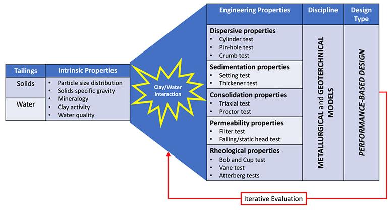
Figure 1—TSF performance-based design philosophy reliant on an understanding of clay/water interaction
Classification of tailings by clay minerals and pore water chemistry as a basis for safe tailings disposal
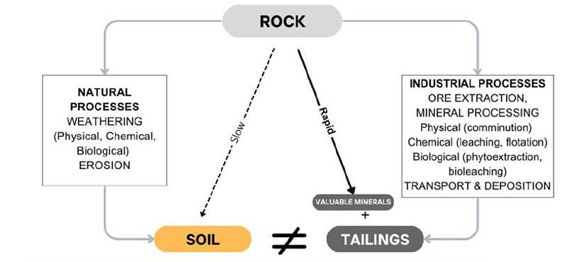
methods resulting after the recoverable metals and minerals have been extracted. Although soils and tailings share a common origin, the nature and duration of the disintegration process varies considerably and therefore, their engineering properties may not be directly comparable (Figure 2).
This paper attempts to provide an alternative view on tailings classification based on the intrinsic properties of the two-phase system. It further attempts to emphasise the importance of the interaction between the clay component and pore water chemistry in defining the engineering properties of the tailings.
Geotechnical test methods
Before discussing classification systems, it is worth considering the currently accepted geotechnical test methods used to measure both intrinsic and derived engineering properties – and to note that pore water chemistry is completely neglected.
In situ tests
In situ tailings properties are typically determined based upon field surveys: seismic cone penetration testing with pore pressure measurements (SCPTu), standard penetration testing (SPT), field shear vane tests, and beach slope measurements. The parameters used to characterise the tailing include a combination of intrinsic and derived engineering parameters, including void ratio, relative density, dilatancy index, and gamma ray absorption from downhole logging, but to name a few.
Table 1
The most common approach to characterise TSF in situ, is to use the piezocone penetration tests (CPTu), where the in situ state parameter (ψ) is inferred, amongst others. The CPTu is capable of providing an accurate profile through the deposited material. The profile will also vary based on the location within the TSF, and depending on the method of depositing the tailings. It is possible to collect samples as part of the CPTu test by piston sampler, Monster Steek Apparaat (MOSTAP), or similar. The sampler is pushed to the test depth and then opened to recover the soil in the target zone. Sampling does not need to be at every CPTu sounding, but once the characteristic soils have been identified, sufficient samples need to be recovered to characterise the variability of parameters, such as grain size.
Laboratory tests
Laboratory tests include foundation index (including plasticity), shear strength, permeability and consolidation tests. An overview of the most common tests for a filtering geotechnical application is summarised in Table 1.
Current tailings classification systems
Soil types have traditionally been classified based on a combination of intrinsic and derived engineering properties, for instance, the Unified Soil Classification System (USCS) classifies soils based on their intrinsic particle size and derived plastic (rheological) properties using Atterberg limits as measured parameters (Figure 3). The Atterberg limits define the plastic behaviour of fine-grained soils by three key parameters:
➤ Liquid limit (LL): the water content at which soil transitions from liquid to solid-like state. The LL is understood as the water content at which the undrained shear strength (or yield strength) is in the order of 1.7 kPa (Sharma, Bora, 2003).
➤ Plastic limit (PL): the water content at which the soil changes from a ductile to a brittle state. The PL is understood as the water content at which the undrained shear strength (or yield strength) is about 170 kPa (Sharma, Bora, 2003).
➤ The plasticity index (PI) is the moisture content difference between the LL and PL. High PI is indicative of a high clay mineral content while a low PI is indicative of a high silt content.
Overview of filtered tailings tests and properties (after Meneses et. al., 2024)
Criteria Description Recommended laboratory test
Atterberg limits Determines filtration moisture content relevant to geotechnical design, typically at the plastic limit (PL) of the material and below the liquid limit (LL).
Clay mineralogy Identifies fine-grained phyllosilicate minerals (< 2μm).
Compressibility of material Evaluates volume compressibility and consolidation behaviour under load.
Particle size distribution (PSD)
Examines how tailings react to filtration systems.
Settling tests Evaluates settling rate, filterability, reagent effects, consolidation, and density of tailings. Drained and undrained settling tests for various PSDs.
Fall cone test (preferred over Casagrande Cup for low plasticity materials).
Cation exchange capacity testing; x-ray diffraction analysis; QEMSCAN.
Various PSDs; constant rate of strain consolidation testing (oedometer).
Hydrometer testing or laser diffraction for fines gradation
Standard jar tests with specified beaker dimensions; Extended duration tests (up to five days) for various clay content levels; Tests should use process water for an accurate representation
Insights
Analysis of filtration moisture content in relation to PL and LL; assesses the influence of climate variability.
Swelling clays can affect filtration rates due to moisture absorption.
Key to understanding water release during settling; insight into active consolidation water release.
Identifies fine particle content and its effect on cake formation; notes how water absorption and adsorption increase with finer particles (e.g., clays), affecting filterability.
Provides analysis of settling time and density specific to tailings type; includes determination of non-segregating boundary.
Provides insight into the water balance in the tailings storage facility and the effect of clays and process reagents on recovery rates.
Figure 2—Origin of soils and tailings (after Kovacevic et al., 2025)
Classification of tailings by clay minerals and pore water chemistry as a basis for safe tailings disposal
This system can conveniently classify soils into plastic or cohesive groups, with corresponding low permeability properties, and non-plastic or non-cohesive groups, with corresponding high permeability properties. Although the method is useful, it has inherent flaws, since these derived properties are dependent on interactions between intrinsic properties such as the active clay content and the pore water, which are often not considered, and which will affect the engineering behaviour of the soil or tailings.
Likewise, the ICOLD Bulletin 181 (ICOLD, 2021) proposes a tailings classification method based on a combination of intrinsic and derived tailings properties such as:
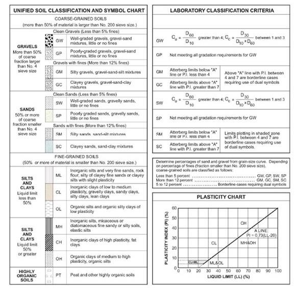
Table 2
1. The solids specific gravity.
2. The solids particle size distribution using the ASTM definition of fines and sand fractions nominally at 75 µm. The fines fraction is further subdivided into silts and clay fractions at the conventionally accepted definition for clays of -2 µm.
3. The tailings ‘activity’ defined by the relationship between the PI and the clay size fraction.
A summary of the ICOLD tailings classification scheme is provided in Table 2.
Although the scheme is useful for providing a descriptive framework for classifying tailings, it does have some shortcomings. Firstly, it assumes that tailings particle size distributions will fall into these groups, which is not always the case (Kovacevic et al., 2025).
A more useful approach would be to define a suitable particle size parameter (such as the percentage -20 µm fraction) with which to classify the intrinsic particle size properties of tailings into one of the five groupings (Figure 4).
Secondly, although the scheme recognises the importance of clays as a key parameter in determining engineering properties such as consolidation and hydraulic behaviours, these are based on the PI, which itself is a derived tailings property and dependent on intrinsic properties such as the active clay content and the pore water chemistry (Table 3).
Alternative tailings classification system
An alternative tailings classification system is proposed based on the intrinsic properties of the solids and the water components separately.
Tailings solids component
The fine solids component of a tailings is widely regarded as the fraction which determines its engineering properties and is also the fraction in which the clay minerals are concentrated. The ASTM grain sizing classification defines the -75 µm fraction as the fines component, while the USCS classification system defines the -2 µm fraction as the clay component. From practical experience
Summary of tailings types and geotechnical classification (ICOLD, 2021)
Tailings type Symbol Description (compare)
Example of mineral/ore
Coarse tailings CT Silty SAND, non-plastic. Salt, mineral sands, coarse coal rejects, iron ore sands. Hard rock tailings HRT Sandy SILT, non to low plasticity. Copper, massive sulphide, nickel, gold.
Altered rock tailings ART Sandy SILT, trace of clay, low plasticity, bentonitic clay content.
Fine tailings FT SILT, with trace to some clay, low to moderate plasticity.
Ultra fine tailings UFT Silty CLAY, high plasticity, very low density and hydraulic conductivity.
Porphyry copper with hydrothermal alteration, oxidised rock, bauxite, leaching processes.
Iron ore fines, bauxite (red mud), fine coal rejects, leaching processes, metamorphosed/weathered polymetallic ores.
Oil sands (fluid fine tailings), phosphate fines; some kimberlite and coal fines.
Figure 3—Unified Soil Classification System (USCS) showing plasticity chart
Figure 4—Typical gradation range for tailings types (left) and range of plasticity index and clay fraction (Activity) for different clay types and tailings type (right) (after ICOLD, 2021)
Classification of tailings by clay minerals and pore water chemistry as a basis for safe tailings disposal
Tabel 3
Clay influence on hydraulic conductivity, settling properties, and moisture sensitivity
Clay type Plasticity Activity index
Rock flour Nonplastic
Kaolinite Low plasticity
Illite Medium plasticity
Montmorillonite High plasticity
0.0
Hydraulic conductivity Settling characteristics
Hydraulic conductivity directly related to Hazen values.
0.40 Upper end of clay hydraulic conductivity.
0.90 Intermediate hydraulic Conductivity between kaolinite and montmorillonite.
Generally good settling properties.
Generally good settling properties.
Intermediate between kaolinite and montmorillonite.
>1.5 Very low permeabilities. Poor settling properties with light weight flocs easily disturbed by wind and wave. Slow rate of consolidation.
using data derived from the laser diffraction sizing method, the 20 µm fraction appears to be a suitable size parameter to distinguish ‘fines’ from ‘coarse’ solids. This criterion therefore includes all solids defined as medium to fine silts and clays according to the USCS system (Figure 5).
The second intrinsic solids parameter to consider is the clay minerals within the fines fraction. Clays are classified according to both crystal structure and surface layer charge (Figure 6).
Surface charge expression does not follow a linear relationship when clays are suspended in water, and only certain clay types are able to absorb water molecules between the crystal layers and undergo swelling and dispersion. These clays are known as swelling or active clays and typically belong to the smectite, vermiculite and illite clay groups. Their intrinsic surface charge property can be measured indirectly by the methylene blue method to provide a methylene blue index (MBI) value in meq/100 g of solids (Kaminsky, 2014). The MBI value therefore provides an indirect measure of the intrinsic surface charge of the active clays and provides an indication of potential for the clay to swell or disperse within the tailings (Figure 7).
When these two intrinsic solids’ properties are plotted together, mineral tailings can be grouped into classes based on their fines/ silt content and their clay dispersive potential. This classification reflects the Skempton activity chart (Mitchell, Soga, 2005), however it is fully based on the intrinsic properties of the solids component of the tailings and can incorporate the ICOLD tailings classification nomenclature based on a 20 µm sizing criteria (Figure 8).
4Tailings water component
The dispersive potential of clays within tailings is only expressed when the clays are exposed to water and depends on the chemical properties of the water (process water or pore water). During processing, the dry ore is typically wetted at the milling or
Constructability
Moisture sensitive during construction.
Sensitive to moisture content during construction and exhibits moderate consolidation rates.
Intermediate between kaolinite and montmorillonite.
scrubbing step and should active clays be present, they will begin to undergo hydration and ion exchange to mimic the ionic profile of the contacting water. Consequently, the chemical properties of the water and the resulting ion exchanged nature of the clays will affect their dispersive behaviour within the slurry. This behaviour will in turn have a profound effect on the engineering properties of the tailings, from sedimentation and rheological properties in the dewatering circuit through to the consolidation and permeability properties at the TSF (Figure 9).
In many respects, the dispersive behaviour of tailings bears a striking similarity to the characteristics of a class of agriculturally problematic soils known as ‘saline/Sodic’ soils, which are classified on the intrinsic properties of two water chemistry related parameters (Richards, 1969):
1. Conductivity (in mS/cm) measures the total water-soluble salt content, i.e., the salinity of the water.
2. Sodium adsorption ratio (SAR), which is a calculated ratio of monovalent sodium ions to divalent calcium and magnesium ions, i.e., the sodicity of the water.
Using these parameters, agriculturalists have devised a classification scheme to define clay dispersive behaviour and to classify soils into four groups (Rengasamy, 2018; Fitzpatrick et al., 1994) (Figure 10).
1. Saline soils - In general soils with conductivities greater than 2 mS/cm (using the Australian standards). The high pore water salt content tends to prevent clay particle dispersion and therefore the soil structure and permeability are maintained.
Figure 5—Grain size definitions according to various soil and agricultural standards (after Hestera et al., 2023)
Figure 6—Classification scheme for clays (after Grim, 1968)
Classification of tailings by clay minerals and pore water chemistry as a basis for safe tailings disposal
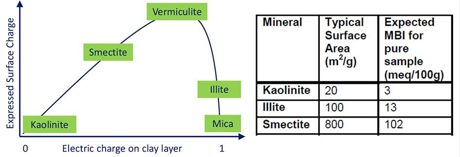
2. Sodic soils – In general, soils with SAR values greater than 6 (using the Australian standards). The high pore water sodium ion concentration allows the active clays to become sodiumion exchanged and highly dispersive, which destroys the soil structure and reduces permeability.
3. Saline/sodic soils – Behave in the same manner as saline soils.
4. Normal soils – the low pore water sodium ion concentration allows the active clays to become calcium- or magnesiumion exchanged and non-dispersive, which maintains the soil structure and permeability
Case study
The mode in which tailings engineering properties are modified by the interaction between the active clay minerals and pore water chemical quality is demonstrated in a case study involving a kimberlite tailings originating from a diamond mine in Angola. Under natural conditions, the active clays within these tailings are known to undergo uncontrolled dispersion due to the exceptionally good quality of the mine process water (very low conductivity) and they remain non-settling when deposited into the TSF.
The behaviour of a naturally uncontrolled dispersive tailings sample was compared to a similar tailings sample, which had undergone controlled dispersion by suspending it in a process water,
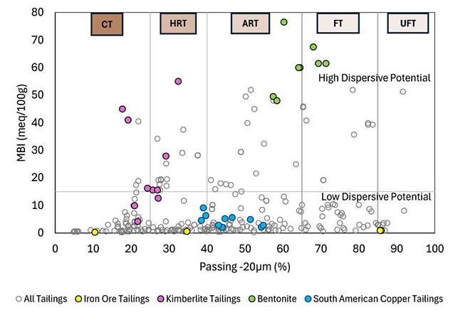
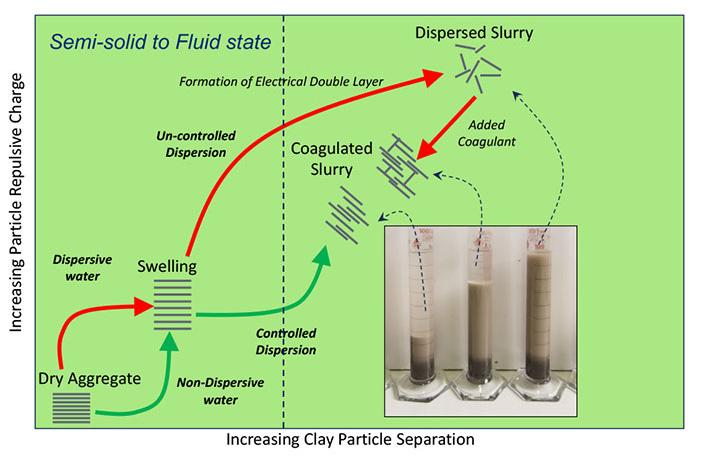
which had been modified using a chemical reagent to have a higher conductivity. In this case only a very small reagent dose (0.25 kg/l) was required to increase in the conductivity (salinity) from 0.4 mS/ cm to 0.6 mS/cm for the clays to be altered from dispersive to nondispersive conditions. The test was repeated at full-scale on the mine site and similar results were obtained, indicating that dispersion behaviour can be controlled and is scalable from laboratory tests (Figure 11).
This change in pore water chemical state had a significant effect on the intrinsic properties of the solids within the tailings, with the controlled dispersive sample having a coarser particle size distribution, especially at the 20 µm size range and a reduced clay dispersive potential (MBI). Accordingly, the change in water chemistry shifted the classification of the kimberlite tailings from hard rock tailings (HRT) in the uncontrolled dispersive state to coarse tailings (CT) in the controlled dispersive state (Figure 12).
The rheological properties of both the uncontrolled and controlled dispersive slurry samples were measured using a rheometer with a bob and cup fitting, and the relationship between sheared yield stress and slurry solids concentration (%m) were described by derived exponential equations. Using these equations and extrapolating the data, slurry solids concentrations (%m), which corresponded to 1.7 kPa and 170 kPa were determined (Figure 13). These slurry mass solids concentrations were then converted to geotechnical moisture content (%) before the Atterberg limits (LL, PL, and PI) were determined and plotted on the Plasticity Chart (Figure 14).
These results clearly show that the engineering properties of a single tailings material can be considerably altered by the interaction of the active clays and chemical state of the pore water. In this case, a slight increase in pore water conductivity changed the interactive state of the clays within the tailings from a high plasticity material to a medium plasticity material. It is also recognised that this effect may also be reversable with all of the negative-associated strength and permeability properties.
Conclusion
The effective classification of tailings is paramount for understanding its behaviour and ensuring safe disposal in TSF sites. For plastic and cohesive tailings, the intrinsic properties of the solids, particularly clay minerals, and the chemical characteristic of the pore water significantly influence the engineering and dewatering properties of tailings.
This proposed alternative classification scheme separates intrinsic solids and water components, using the 20 µm particle size threshold to define fines and employing the MBI to quantify active clay surface charge, indicating swelling and dispersive potential of the tailings. Expression of this potential is dependent on the pore water chemical properties, such as conductivity, SAR, and pH, which in effect imparts the macro-textural and strength properties
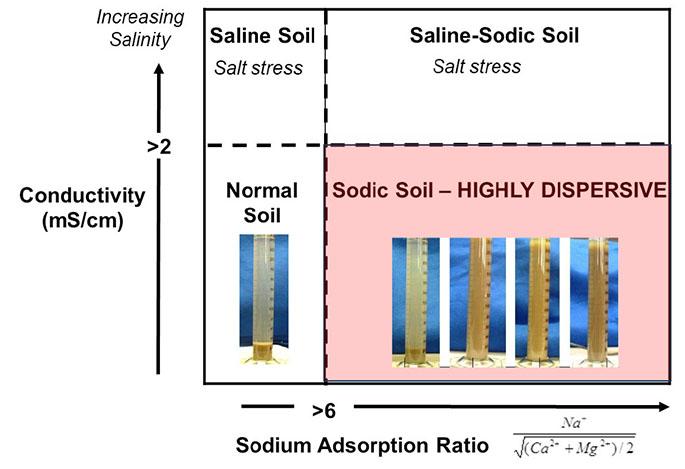
Figure 7—Clay surface charge expression and typical MBI values for pure clays (after Kaminsky, 2014)
Figure 8— Tailings solids dispersive potential classification chart
Figure 9—Controlled and uncontrolled dispersion of clays in water (after Rengasamy, 2018)
Figure 10—Classification scheme for defining saline sodic soils (after Fitzpatrick et al., 1994)
Classification of tailings by clay minerals and pore water chemistry as a basis for safe tailings disposal
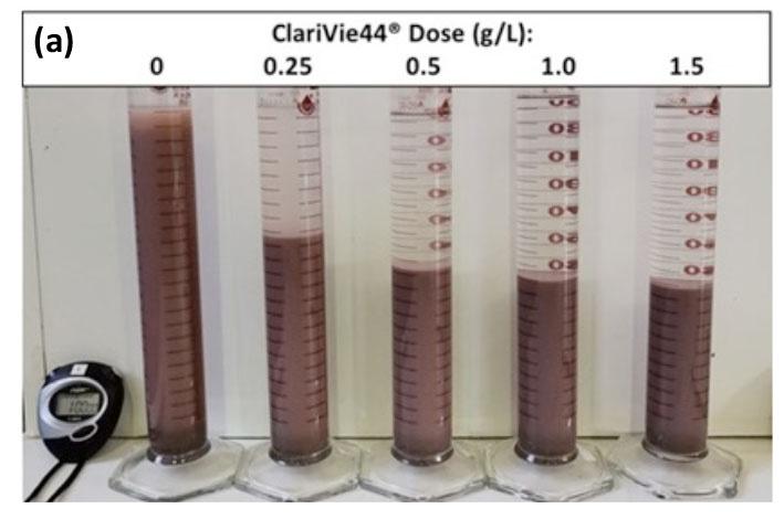
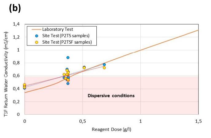
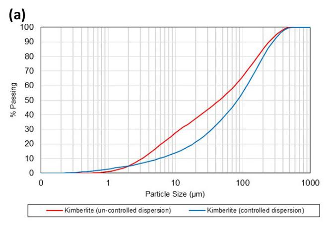
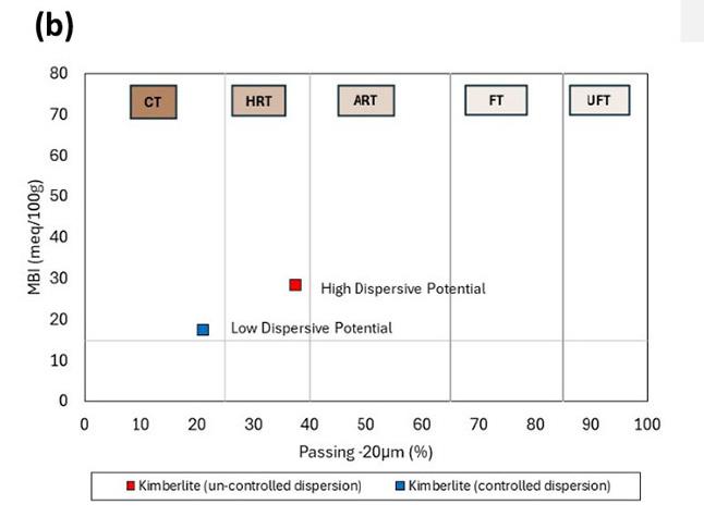
Figure 12—Tailings solids intrinsic properties under dispersive and non-dispersive conditions (a) changes in particle size distribution; (b) changes in tailings classification
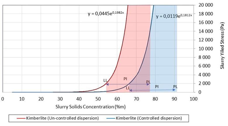
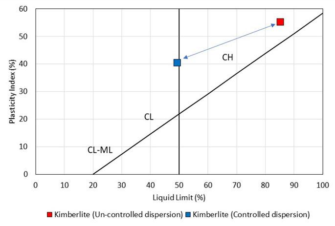
14—Tailings samples plasticity properties
to the tailings.
An understanding of the interactions between these fundamental components, in especially the clay-containing tailings, is an essential foundation for adopting a performance-based design philosophy.
References
Fitzpatrick, R.W., Boucher, S.C., Naidu, R., Fritsch, E. 1994. Environmental consequences of soil sodicity. Australian Journal of
Soil Research, vol 32. pp. 1068–1093.
Grimm, R.E. 1968. Clay Mineralogy (2nd ed). McGraw Hill, New York.
Hestera, H., Pahernik, M., Kovacevic Zelic, B., Maljkovic, M.M. 2023. The United Soil Classification System mapping of the Pannonian basin in Croatia using multinomial logistic regression and inverse distance weighting interpolation. Rudarsko-geološko-naftni zbornik (The Mining-Geology-Petroleum Engineering Bulletin). pp. 147–159.
(ICOLD) International Commission on Large Dams. 2021. Bulletin 181: Tailings Dam Design Technology Update, CRC Press, Boca Raton.ww
Kaminsky, H. 2014. Demystifying the Methylene Blue Index. 4th Int Conf. Oil Sands Proceedings. Lake Louis, Alberta. pp. 221–230.
Kovacevic, Z., Burecic, S., Znidarcic, D. 2025. Geotechnical engineering knowledge base needed for the improvement of mine tailings safety. GEE 2025 – Geotechnical Engineering Education 2025 International Conference “Charting the path toward the future”. Nancy, France. pp. 1–12.
Meneses, B., Llano-Serna, M., Dressel W., Coffey P., Gerritsen T. 2024. A geotechnically derived screening method to assess the filterability of tailings. Paste 2024, Melbourne, Australia, pp. 115–126.
Mitchell, J.K., Soga, K. 2005. Fundamentals of soil behaviour. 3rd Ed, Wiley & Sons. New Jersey.
Morrison, K.F. 2022. Tailings Management Handbook – A life-cycle approach. Society for Mining, Metallurgy & Exploration, Colorado.
Rengasamy, P. 2018. Irrigation water quality and soil structure stability – A perspective with some new insights. Agronomy. 8. pp. 72–85.
Richards, L.A. (ed.) 1969. Diagnosis and improvement of saline and alkali soils. US Dept Agriculture Handbook No. 60.
Sharma, B., Bora, P.K. 2003. Plastic limit, liquid limit and undrained shear strength of soil—reappraisal. Journal of Geotechnical and Geoenvironmental Engineering August. pp. 774–777.
United Soil Classification System (CSCS), California Department of Transport (Caltrans). https://dot.ca.gov/-/media/dot-media/ programs/maintenance/documents/office-of-concrete-pavement/ pavement-foundations/uscs-a11y.pdf u
Figure 11—Modification of tailings dispersive properties by increasing process water conductivity (a) laboratory trial; (b) site trial
Figure 13—Tailings samples rheological properties
Figure
Affiliation:
1 Knight Piésold Consulting, Johannesburg, South Africa
2 SRK, Johannesburg, South Africa
3 University of Pretoria, Pretoria, South Africa
Correspondence to: E. Zannoni
Email: ezannoni@knightpiesold.com
Dates:
Received: 4 Feb. 2026
Published: April 2026
How to cite:
Zannoni, E., Grobler, T., Heymann, G..2026. Characterisation of the reworked residual norite in the Rustenburg region of South Africa. Journal of the Southern African Institute of Mining and Metallurgy, vol. 126, no. 4, pp. 241 –246
DOI ID:
https://doi.org/10.17159/2411-9717/983/2026
ORCiD:
G. Heymann
https://orcid.org/0000-0002-2338-4073
This paper is based on a presentation given at the Tailings 2026 - Where To Now? Conference, 3-4 March 2026, Indaba Hotel, Spa and Conference Centre, Fourways
Characterisation of the reworked residual norite in the Rustenburg region of South Africa
by E. Zannoni1, T. Grobler2, G. Heymann3
Abstract
Many tailings storage facilities in the Rustenburg region of South Africa’s North-West Province are founded on reworked residual norite derived from the weathering of the Bushveld Igneous Complex. The weathering of these rocks results in the formation of residual soils, typically characterised by high-reactivity clays near the surface, grading into coarser materials with depth. The upper horizon, commonly referred to as reworked residual norite or black turf, typically comprises of clay contents of up to 80% with high plasticity. Cyclic swelling and shrinkage result in remoulding and the development of non-continuous slickensides characteristic of residual soils.
With the implementation of the Global Industry Standard on Tailings Management, increased emphasis is placed on robust material characterisation, as this layer frequently controls tailings storage facility stability under both drained and undrained conditions. Laboratory testing is challenging due to very low permeability, high overconsolidation, and a nonlinear shear strength envelope characterisation, with yield stresses of approximately 800 kPa. Oedometer results show decreasing coefficients of volume compressibility and consolidation with increasing stress, likely due to closure of microfissures.
Undrained triaxial shear testing on undisturbed and compacted specimens indicates contractive behaviour, with peak strength mobilised at shear strains of approximately 7% –10%, followed by mild strain softening. The results support a nonlinear failure envelope for effective stresses below the yield stress, transitioning to linear behaviour at higher stresses.
Keywords
Reworked residual norite (Black turf), Expansive clays, Tailings storage facilities, GISTM, Shear strength, Permeability, Coefficient of consolidation, Coefficient of volume compressibility
Introduction
Tailings storage facilities (TSF) in the Rustenburg area are characterised by a foundation where the presence of reworked residual norite creates a preferential failure plane, given the low shearing resistance. With the introduction of the Global Industry Standard on Tailings Management (ICMM, 2020), a higher degree of confidence in the knowledge base has been requested from stakeholders throughout the entire tailings management system, including the geotechnical characterisation of the soils (foundation and tailings) as well as the behaviour in drained and undrained conditions. Historically, the South African industry only required drained stability, whilst nowadays, emphasis has also been placed on undrained behaviour, both at peak and residual (if applicable) requiring a higher degree of knowledge of the materials, in terms of shearing behaviour.
This paper presents findings from several geotechnical investigations in the Rustenburg area, focusing on the geotechnical characterisation of the reworked residual norite, including index properties and shear strength behaviour from consolidated undrained triaxial testing and direct simple shear testing, and its implications for TSF stability.
A total of 26 samples of reworked residual norite have been considered in this work, logged by a professional registered engineering geologist and classified as reworked residual norite.
Background
Regional geology of the Rustenburg Layered Suite
The Bushveld Igneous Complex comprises the Rustenburg Layered Suite at its base, followed by the Rashoop Granophyre and Lebowa Granite Suite. This mafic to ultramafic pseudo-stratified intrusion includes basal, critical, main, and marginal zones, distinguished by lithologies such as norite,
Characterisation of the reworked residual norite in the Rustenburg region of South Africa
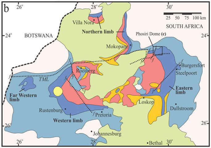
gabbronorite, gabbro, anorthosite, pyroxenite, and chromitite (Brink, 1979). The critical zone, rich in norites, is particularly significant (Bourdeau et al., 2021). Figure 1 highlights the Rustenburg Layered Suite in dark blue.
The western limb, forming an arc from Thabazimbi through Rustenburg to Pretoria, is characterised by norite deposits containing calcic plagioclase, orthorhombic pyroxene, and olivine. These norites weather into expansive montmorillonite clays, with recent geotechnical findings indicating finer textures and higher plasticity indices (PI) compared to the eastern limb—often exceeding 60% clay content—enhancing their expansiveness (van der Merwe, 1967). Pyroxene weathering produces smectite clays that expand with water infiltration and shrink upon drying, causing cracks and uneven surfaces (Netterberg, 2019). Fresh norite is quarried for dimension stone and aggregates, but its residual soils pose significant construction challenges due to pronounced shrinkswell behaviour. These soils display a shattered and slickensided soil structure, which indicates soil movements (heaving/ swelling/ desiccation) under changing moisture conditions (Brink, 1979), as illustrated in Figure 2. The upper reworked residual soil texture comprises mainly silt-clay and transitions into silty, gravelly sand derived from the in situ weathered parent rock between 1 m and 2 m below surface (Brink, 1979).
Chemical weathering dominates under a Weinert N-value > 5, with climate and topography, assessed via land facet mapping, shaping these properties.
The eastern limb, extending from Mokopane to Stoffberg, shares stratigraphic similarities but differs notably. Its critical zone thins and disappears from Burgersfort to Stoffberg, likely reducing norite
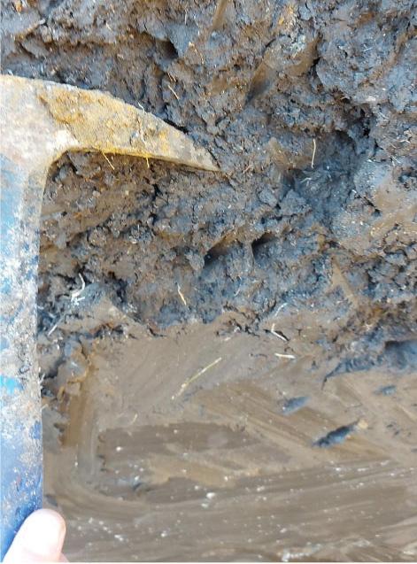
abundance and resulting in coarser materials with lower PI values (Cooper et al., 1998). The rugged topography and wetter climate may accelerate weathering, potentially increasing montmorillonite content, yet the finer, higher-PI western limb soils appear more expansive. These differences highlight the need for site-specific geotechnical assessments to mitigate construction risks across both limbs.
Scope
Due to the inherent variability of soil and even more for residual soils such as the reworked residual norite, with challenges in gathering accurate soil indicators and shear strength behaviours, the paper aims to provide the results of years of investigation informed by a robust sample size with 26 samples, 71 shear tests (68 isotropically consolidated undrained triaxial tests and 3 direct simples shear tests , 2 permeability tests, 3 consolidations tests and 3 Bromhead ring shear tests).
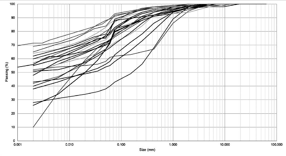
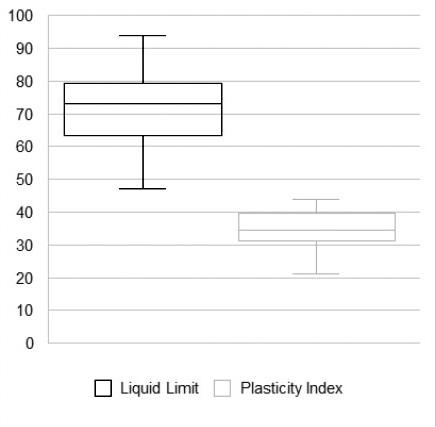
Figure 1—Map showing the extent of the Bushveld Igneous Complex rocks, with the Rustenburg Layered Suite in dark blue (Bourdeau et al., 2021)
Figure 2—Typical test pit profile of the reworked residual norite with the presence of slickensides
Figure 3—Particle size distribution
Figure 4—Liquid limit and plasticity index variation
Characterisation of the reworked residual norite in the Rustenburg region of South Africa
Indicator test results
The reworked residual norite is a non-homogeneous material, as the mulching effect, given by its very high shrinkage and swelling potential, results in the presence of transported material being present in the upper parts. Generally, it is classified as a clay with high plasticity (CH) according to the Unified Soil Classification System (USCS) classification with a plasticity index above 20 and, in some instances, a clay fraction of more than 50%, as illustrated in Figure 3 and Figure 4. The permeability measured in a triaxial apparatus of two specimens compacted at 90% standard Proctor was measured as 1 x 10⁻⁸ m/s. The average specific gravity of a number of specimens was found to be 2.64.
Strength behaviour
Critical state soil mechanics framework for clays
Critical state soil mechanics provides a useful framework within which to interpret the behaviour of clay, although it makes some simplifications, which may not be appropriate for all clays. Figure 5 shows the critical state framework for clay in mean effective stress (p') vs. deviatoric stress (q') space. It suggests that normally consolidated clay (A) or lightly overconsolidated clay (B) will reach the Roscoe surface and then contract before failing at the critical state line (CSL). The critical state line passes through the origin, which implies that normally consolidated or lightly overconsolidated soil has no strength at zero normal effective stress. In contrast, heavily overconsolidated clay (C) will yield at the Hvorslev surface and dilate before reaching the critical state line. The Hvorslev surface is often assumed to be a straight line and the extension of the Hvorslev surface (dashed line) has a positive intercept with the deviatoric stress axis (q'), as shown in Figure 5. The framework suggests that the failure envelope for clay sheared with an initial mean effective stress (p'i) greater than p'x ,will be linear and pass through the origin (i.e., have no cohesion intercept). In contrast, soils with an initial mean effective stress (p'i) less that p'x, will have a failure envelope above the critical state line (CSL).
Many engineers prefer to use the Mohr Coulomb failure envelope as failure criterion for soil (Equation 1). The equation assumes that the failure envelope is a straight line defined by two soil parameters: c' and Ø'.
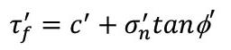
where:

: shear stress on the failure plane at failure

: normal effective stress on the failure plane at failure
Equation 1 can be used for both normally consolidated soils, where the failure envelope passes through the origin by taking c' = 0 and heavily overconsolidated soils by taking c' > 0. However, from
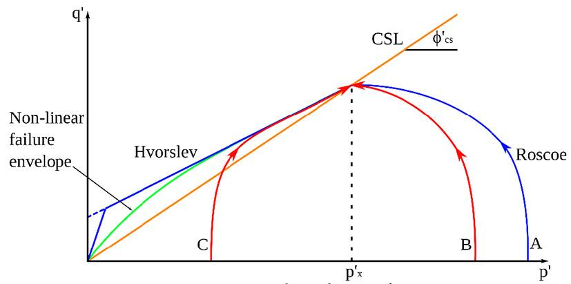
Figure 5 it is clear that the friction angle Ø' is not the same for these two cases.
It is well known that the failure envelope for rocks is nonlinear, e.g., Hoek and Brown (1980) and numerous other authors have shown that the failure envelope for soils is also nonlinear. Various nonlinear function types have been suggested to define the curvature of the failure envelope for soils. These include bilinear envelopes (Baker, 2004), hyperbolic functions (Maksimovic, 1989) and power functions (Perry, 1994; Heymann, 2016). It is important to note that a value of the parameter c' greater than zero, does not necessarily imply shear strength at zero normal effective stress. It may simply be a consequence of the assumption that the MohrCoulomb envelope is a straight line fitted to some portion of a nonlinear failure envelope.
From the aforementioned discussion it is clear that, when conducting triaxial testing with the aim of quantifying the shear strength of soils, the applied effective stresses should be considered carefully. Preferably, the tests should be conducted in the same stress range to which the soil will be subjected in the field. For instance, if a tailings dam is founded on a heavily overconsolidated clay, but during triaxial testing high effective normal stresses are applied causing the clay to be normally consolidated, the failure envelope will pass through the origin. But if the same overconsolidated soil is tested at lower normal effective stresses, the failure envelope will be nonlinear. However, many commercially available slope stability programs use the straight-line Mohr-Coulomb failure envelope (Equation 1) as failure criterion. But, if the failure envelope is nonlinear, as shown in Figure 5, assigning the appropriate c' and Ø' can be challenging, and the parameters c' and Ø' should not be evaluated in isolation. For heavily overconsolidated clay, it would be inappropriate to use Ø' cs together with c' = 0, which would lead to an underestimation of the strength of the soil.
Interpretation of triaxial test results
Figure 6 shows the stress paths for 68 isotropically consolidated undrained triaxial tests on reworked residual norite from the western limb according to ASTM 4767, conducted for a number of projects by four commercial soils laboratories. Tests were conducted on both undisturbed and compacted specimens. Also shown is the failure envelope in red with form where A = 3.25 and b = 0.77. The failure envelope gives a reasonable state boundary to the triaxial stress paths and also shows that the failure envelope is nonlinear. Due to a shear banding behaviour at higher strains, the stress paths have been trimmed as it is not a representative shearing behaviour of the whole sample, therefore, residual behaviour cannot be estimated. Thus, direct simple shear testing has been considered for residual behaviour.
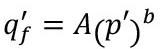
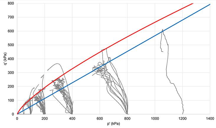
Figure 5—State boundary surface
Figure 6—CIU stress paths for reworked residual norite
Characterisation of the reworked residual norite in the Rustenburg region of South Africa
Mesri and Abdel-Ghaffar (1993) proposed a nonlinear failure envelope described by Equation 2.
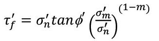
where:

: pre-consolidation pressure
m: material parameter
Figure 5 shows that for the critical state framework, the boundary between the linear and nonlinear portions of the failure envelope is the mean effective stress at the apex of the state boundary surface (p'x), however Mesri and Abdel-Ghaffar (1993) proposed to use the pre-consolidation pressure as the boundary. In the context of residual clays such as reworked residual norite, it may not be appropriate to use the term “pre-consolidation pressure”, as pre-consolidation pressure is typically taken as the maximum effective stress to which a soil has been subjected in the past. A more appropriate term is “yield stress”. Murison et al. (2025) conducted one-dimensional load tests on samples of reworked residual norite from a site on the eastern limb near Steelpoort and estimated the vertical effective yield stress to be 800 kPa. The attraction of Mesri and Abdel-Ghaffar’s (1993) formulation of the failure envelope is that it is nonlinear for overconsolidated clay and linear for normally consolidated clay. This conforms closely to the nonlinear envelope shown in Figure 5 for mean effective stresses less than p'x and the linear critical state line for mean effective stresses greater than p'x
Figure 7 shows the shear stress on the failure plane at failure (τ'f ) and the normal effective stress on the failure plane at failure (σ'n) for the same data, as presented in Figure 6. Also shown in the figure is the failure envelope using Equation 2 with Ø' = 15°, σ'm = 800 kPa, and m = 0.7. The parameters were chosen not to give an upper bound envelope, but to represent a good fit to the triaxial results. Figure 7 shows that at low mean effective stress (less than 100 kPa) an appropriate Mohr-Coulomb failure envelope may pass through the origin (c' = 0), but with Ø' significantly higher than 15°. In contrast in the stress range 200 kPa – 400kPa, a friction
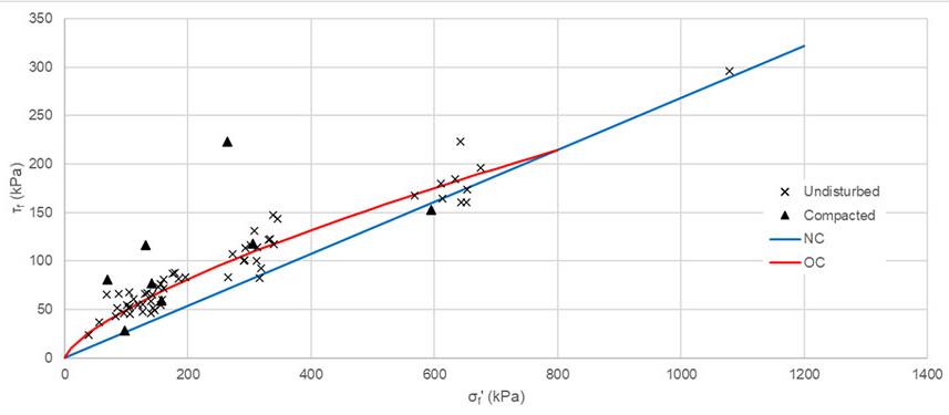
angle Ø' close to 15° may be appropriate, but will require a cohesion intercept c' > 0 to accurately express the strength of the soil. As stated previously, the parameters c' and Ø' cannot be evaluated in isolation. To illustrate this, a failure envelope with friction angle Ø' = 15° with c' = 0, is shown in Figure 6 as the blue line. It shown that if this failure envelope is used for reworked residual norite at a mean effective stress (p') less than 800 kPa, the strength of the soil will be significantly underestimated.
Interpretation of direct simple shear results
Direct simple shear (DSS) tests were performed on undisturbed specimens in accordance with ASTM D6528 to simulate undrained horizontal shearing at constant volume. Consolidation stresses of 200 kPa, 400 kPa, and 600 kPa were applied to bracket anticipated foundation stresses.
Peak shear stress and shear stress at 15% shear strain were adopted as failure criteria, with residual values recorded at large displacements. Results are summarised in Table 1.
Normalised undrained shear strength ratios range from 0.24 to 0.29 at peak and 0.19 to 0.28 at 15% strain, showing mild reduction with increasing consolidation stress—consistent with strainsoftening in overconsolidated clays. Stress–strain response (Figure 8) indicates contractive behaviour with peak strength mobilised at 7% – 10% shear strain, followed by gradual softening toward a stable residual plateau. The absence of pronounced brittleness suggests ductile post-peak response under monotonic loading.
Interpretation of ring shear results for residual strength
Residual shear strength parameters were determined using the Bromhead ring shear apparatus on remoulded and pre-sheared specimens, consolidated at normal effective stresses of 75 kPa, 150 kPa, and 300 kPa. Testing followed ASTM D6467, with specimens sheared to high strains to ensure full mobilisation of the residual condition. Table 2 provides a summary of the ring shear results.
Figure 9 shows shear stress versus displacement, illustrating a progressive transition from peak to stable residual values after about 20 mm of displacement. The failure envelope (Figure 10) is near linear and passes through the origin, with a residual friction angle of 8.5° with zero effective cohesion.
These parameters represent the large-displacement condition and are applicable only where pre-existing aligned slickensided surfaces or progressive failure mechanisms are present. The exceptionally low friction angle is consistent with alignment of platy clay minerals along polished shear planes.
Caution is required in applying these values; they constitute a lower-bound strength and should be used only in conjunction with strain compatibility assessments and consideration of displacement magnitude.




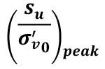
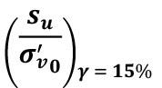
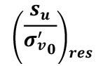
Figure 7—Failure points for reworked residual norite
Table 1
DSS result summary
Characterisation of the reworked residual norite in the Rustenburg region of South Africa
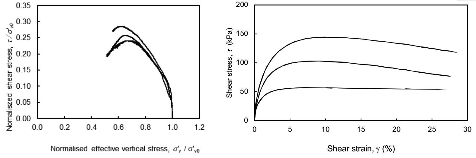
Table 2
Ring shear result summary
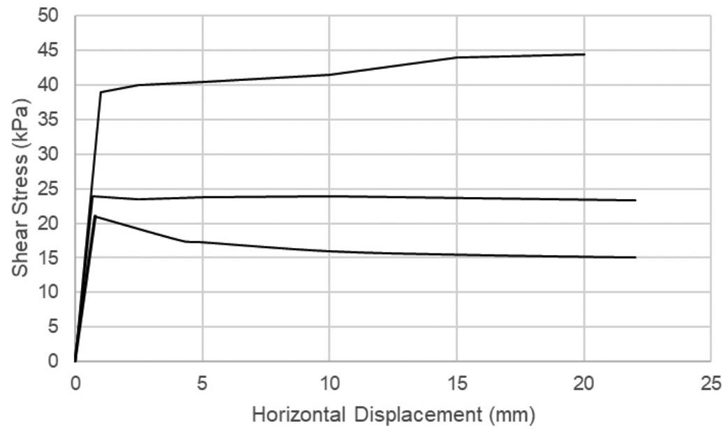
Table 3
Oedometer result summary
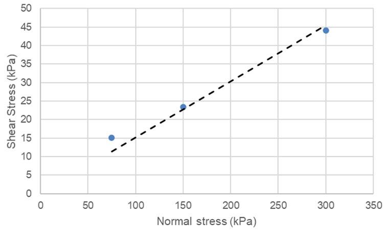
Stiffness behaviour
Oedometer tests were conducted on undisturbed tube samples of reworked residual norite in accordance with ASTM D2435. Initial void ratios ranged from 0.57 to 0.81, consistent with field densities. Upon inundation under a seating stress of 6 kPa immediate and substantial swell strains were observed reflecting the highly expansive montmorillonite and smectitic clay mineralogy. Table 3 provides a summary of the oedometer results.
Specimens were loaded incrementally to a maximum vertical effective stress of 1600 kPa, followed by unloading to 25 kPa. Figure 11 presents the void ratio versus log effective vertical stress relationship for three representative specimens.
Figure 8—Direct simple shear results
Figure 9—Shear stress vs Horizontal displacement of ring shear results
Figure 10—Shear stress vs. normal stress of ring shear results
Characterisation of the reworked residual norite in the Rustenburg region of South Africa
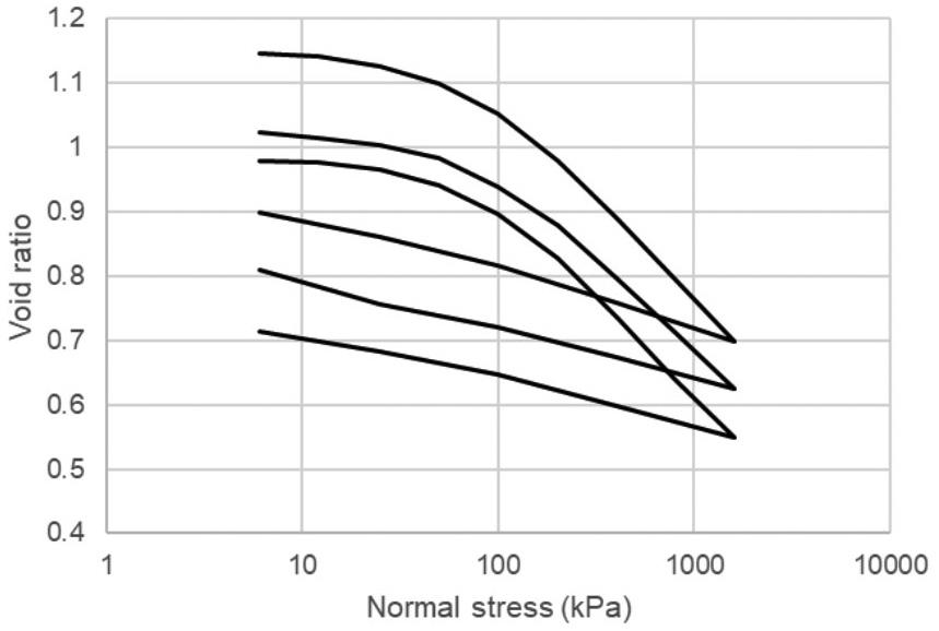
Coefficients of volume compressibility (mv) decrease from 0.48 MPa-¹ (at 25 kPa – 50 kPa) to 0.07 MPa-¹ (at 800 kPa – 1600 kPa), while coefficients of consolidation (cv), evaluated via the Casagrande log-time method, range from 0.03 m²/year to 5.65 m²/ year, with a general reduction at higher stress levels, possibly due to closure of microfissures.
Conclusions
Many tailings storage facilities (TSF) are located in the Rustenburg region of South Africa founded on an upper layer of reworked residual norite. The reworked residual norite is characterised by a high percentage of clay (up to 80%) with a PI above 20. Due to the high swell and shrinkage potential, remulching is common, which results in the presence of slickensides. These planes are not aligned and non-continuous, which is characteristic of residual soils, rather than transported soils. Ring shear results yield a residual friction angle of 8.5°. The oedometer test results presented, indicate the coefficient of volume compressibility (mv) and the coefficient of consolidation (cv) both reducing at increasing stress levels. The reduction in coefficient of consolidation (cv) is possibly due to closure of microfissures. The permeability of the reworked residual norite, measured in the triaxial apparatus, is of the order of 10-8 m/s.
GISTM places a high demand on material characterisation in terms of shear behaviour for stability purposes. This has resulted in extensive shear strength characterisation of this material for stability analysis. The critical state framework suggests that overconsolidated clays have a nonlinear failure envelope, which poses challenges when applying a linear failure envelope such as the Mohr-Coulomb failure criteria. Due to the broad range of effective stress that a TSF is subject to, the failure envelope suggested by Mesri and AbdelGhaffar (1993), which provides nonlinear strength behaviour for overconsolidated clay and linear for normally consolidated clays, was applied to undrained triaxial shear data. The reworked residual norite has a yield stress of the order of 800 kPa, therefore suggesting a nonlinear behaviour for effective stresses less than 800 kPa and linear behaviour for higher stresses. Furthermore, the reworked residual norite exhibits contractive behaviour with a peak strength mobilised at 7% to 10% shear strain with a mild strain softening. A significant number of undrained triaxial shear results are presented for both undisturbed and compacted specimens. The tests were performed by a number of different laboratories allowing general conclusions to be made regarding the shear behaviour over a large range of effective stresses. However, because of the variability of
residual soils, especially the reworked residual norite, site-specific investigations are recommended in line with the Site Investigation Code of Practice (SAICE, 2010) for critical structures such as TSFs, as the repercussions of instability for the industry, environment, and society are severe.
Acknowledgements
The authors would like to acknowledge G. Wiid and R. Cooper for their contributions to the database presented in this paper.
References
Baker, R. 2004. Nonlinear Mohr Envelopes Based on Triaxial Data. Journal of Geotechnical and Geoenvironmental Engineering, vol. 130, no. 5, pp. 498–506.
Brink, A.B.A. 1979. Engineering Geology of Southern Africa, Volume 1., Chapter 10 Bushveld Complex, Rooiberg Group and Rustenburg Layered Suite, pp. 277–301.
Bourdeau, J., Hayes, B., Zhang, S., Logue, A., Bybee, G. 2021. Origin and significance of noritic blocks in layered anorthosites in the Bushveld Igneous Complex, South Africa. Contributions to Mineralogy and Petrology.
Heymann, G. 2016. Typical strength properties of South African soils. Proceedings of the First Southern African Geotechnical Conference, Sun City, South Africa, 5 - 6 May 2016, pp. 289–294. Jacobsz (Ed.), Taylor and Francis, ISBN 978-1-138-02971-2.
Hoek, E., Brown, E.T. 1980. Underground Excavations in Rock. CRC Press, London, pp. 536.
ICMM, UNEP, PRI. 2020. Global Industry Standard on Tailings Management. International Council on Mining and Metals, London. Available at: https://www.icmm.com/gistm [Accessed 21 April 2026].
Maksimovic, M. 1989. “Nonlinear Failure Envelope for Soils.” Journal of Geotechnical Engineering, ASCE, vol. 115 , no. 4, April. pp. 581–586.
Mesri, G., Abdel-Ghaffar, M.E.M. 1993. Cohesion intercept in effective stress-stability analysis. Journal of Geotechnical Engineering, vol. 119, no. 8, pp. 1229–1249.
Murison, R.A., Gaspar, T.A.V., Jacobsz, S.W., Heymann, G., Osman, A.S. (in print). Practical guidelines on the determination of onedimensional swell properties of highly expansive clays. Canadian Geotechnical Journal.
Netterberg, F. 2019. Identification of Potentially Expansive Clay Soils from Soil Structure. 17th African Regional Conference on Soil Mechanics and Geotechnical Engineering. Cape Town: International Society for Soil Mechanics and Geotechnical Engineering.
Perry, J. 1994. A technique for defining non linear shear strength envelopes and their incorporation in a slope stability method of analysis. Quarterly Journal of Engineering Geology. vol. 27, no 3, pp. 231–241.
South African Institution of Civil Engineering Geotechnical Division. 2010. Site Investigation Code of Practice, 1st edn., South African Institution of Civil Engineering, Johannesburg. Van der Merwe, D. 1967. The Composition and Physical Properties of the Clay Soils in the Mafic Rocks of the Bushveld Igneous Complex. The Fourth Regional Conference for Africa on Soil Mechanics and Foundational Engineering, pp. 141–146. Cape Town. u
Figure 11—Consolidation curves from oedometer results
Affiliation:
1. Clean TeQ Water, South Africa
2. Stitchwise
3. Clean TeQ Water, Australia
4. Harmony Gold
Correspondence to:
J.C. van der Linde
Email: jvanderlinde@cleanteqwater.com
Dates:
Received: 2 Feb. 2026
Published: April 2026
How to cite:
Van der Linde, J.C., Brooks, E.D., Spagnuolo, C., Fischmann, A.J., Raath, J.2026. Improving tailings dewatering with ATA® for paddocked buttress formation: A pilot study. Journal of the Southern African Institute of Mining and Metallurgy, vol. 126, no. 4, pp. 247–252
DOI ID:
https://doi.org/10.17159/2411-9717/967/2026
ORCiD:
J.C. van der Linde
https://orcid.org/0000-0003-4360-4181
This paper is based on a presentation given at the Tailings 2026 - Where To Now? Conference, 3-4 March 2026, Indaba Hotel, Spa and Conference Centre, Fourways
Improving tailings dewatering with ATA® for paddocked buttress formation: A pilot study
by J.C. van der Linde1, E.D. Brooks2, C. Spagnuolo1, A.J. Fischmann3, J. Raath4
Abstract
The St. Helena tailings storage facility, operated by Harmony Gold, receives tailings from several Harmony Gold processing plants in the Welkom area of the Free State, South Africa. To improve structural integrity and extend the operational life of the tailings storage facility, a tailings paddock buttressing method is currently being implemented. In this method, the buttress is constructed using deposited tailings in paddocks, with walls typically shaped and placed by an excavator. Whilst this method provides the necessary structural integrity, it is a time and resource intensive method that is limited by the drainage rate of the ultra-fine tailings, equipment availability, and weather conditions.
This paper demonstrates the use of Clean TeQ Water’s ATA® rapid dewatering technology as an alternative approach, utilising woven geotextile dewatering bags in combination with the ATA® technology to construct and fill the paddock buttress. ATA® is a three-component system where the tailings stream is separated into fines and coarse fractions utilising a hydro-cyclone. These fractions are treated separately with complementary polymeric reagents and recombined to create anchored particles. These anchored particles enhance dewatering performance by capturing the fines and creating a granular agglomerate structure that promotes improved free drainage and rapid water release. A 9 t/h pilot plant was operated on site, benchmarking the ATA® enhanced paddocking method with the current method. The results from the pilot demonstrated that the use of ATA® offers significant advantages, including higher homogeneity in the buttress, higher permeability, and faster settling rates. The moisture content of the ATA®-treated material is lower and trafficability was achieved at an accelerated rate, reducing turnaround time between lifts and enabling more efficient and safer tailings facility management.
Keywords polymers, buttressing, permeability, trafficability, phreatic line, direct deposition
Introduction
Stability of tailings storage facilities (TSF) has become a significant focus following disastrous tailings dam failures worldwide. To manage mining facilities responsibly, there is much emphasis on the urgent need for improved safety standards and measures to control and reduce risks of failure. TSFs often require stability interventions. For a TSF with low stability or uncontrolled seepage, one such stabilisation method is through the construction of a buttress against the existing side slopes. A buttressing solution can increase slope stability, improve the safety factor, and prevent catastrophic failures, therefore improving against a number of the key guidelines prescribed in the Global Industry Standard on Tailings Management (GISTM) (ICMM, 2020). Buttressing involves one basic principle: To provide sufficient dead weight near the toe of a slope to prevent movement, thereby increasing the resisting force and increasing stability (Crous, Jacobsz, 2023).
Harmony Gold’s St. Helena Mine currently operates a surface retreatment operation. The site reprocesses gold-bearing tailings and waste rock from the Free State region in South Africa. The site continues to operate an active TSF to manage the tailings produced in the retreatment operation. To improve structural integrity and extend the operational life of the TSF, St Helena has implemented a tailings paddock buttressing method. In this method the buttress is constructed using deposited tailings in paddocks, with walls typically shaped and placed by an excavator (upstream construction). The construction material and method of constructing the buttress play a major role in the geotechnical properties of the buttress and its stability. Properties such as particle size, density, moisture content,
Improving tailings dewatering with ATA® for paddocked buttress formation: A pilot study
permeability, and homogeneity of the placed material influence how well the material will drain and how it behaves under stress, affecting the dam’s overall stability.
Using the same deposition technique as within the dam to form the buttress is considered acceptable, provided it has the required geotechnical properties to support the dam and significantly improve the slope stability. Constructing stable embankments that have the required geotechnical properties is dependent on material quality and method of deposition. These properties should be present within the buttress to ensure its own stability and to provide support and drainage to improve the dam’s embankment stability.
Clean TeQ Water’s ATA® rapid dewatering technology, a concept that uses novel dual polymer conditioning, can be used to improve the geotechnical properties of the TSF by enabling the placement of homogeneous, high strength conditioned tailings (Spagnuolo et al., 2024) within the paddock buttress with increased permeability, allowing for an advanced dewatering rate, resulting in a lower phreatic surface within the TSF itself.
During the ATA® process, the tailings stream is split into fine and coarse fractions, using a hydrocyclone. The fine and coarse fractions are then treated separately with a pair of complementary polymeric reagents. The fines stream is treated with an activator polymer, while the coarse stream is treated with a tether polymer, creating anchor particles. When the activated fines are combined with the tethered coarse material (anchors), the fine particles are attracted to the anchors, form large agglomerates, and rapidly settle. This process is illustrated in Figure 1. The agglomerate network has a rigid, open structure that rapidly dewaters through a porous medium such as a screen, woven geotextile, or filter. Due to the attractive forces between the fine and coarse particles, low turbidity water is released, and fines capture (and recapture) can be dramatically improved. The deposited material is therefore a homogeneous rigid, open structure material with attractive forces between the fine and coarse particles that could provide an increase in the long-term stability of the tailings buttress.
Objective of the study
This paper demonstrates the application of Clean TeQ Water’s ATA® rapid dewatering technology as an alternative to the conventional paddock buttressing method. The study included operation of a 9 t/h ATA® pilot plant on site, along with tests aimed at characterising the hydraulic and geotechnical properties of materials produced, using both methods in order to compare them.
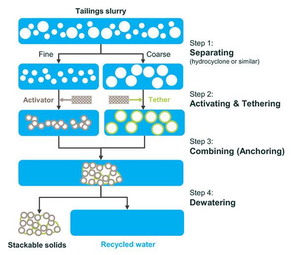
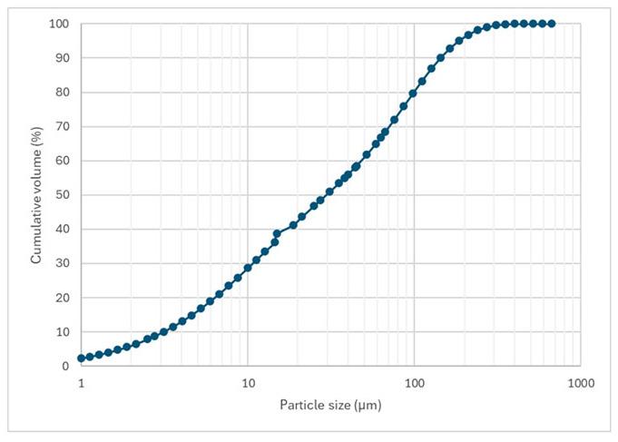
Experimental procedures
Materials
Polymeric reagents
The ATA® activator and tether reagents are proprietary polymers received in a fully desaturated powder form. The polymers were dissolved at 0.2% w/w in return water from the tailings facility. Polymer dosages were optimised based on visual observation of agglomerate formation and settling behaviour.
St. Helena tailings material
The St. Helena TSF is fed with the full plant tailings at a solids flow rate ranging from 700 t/h to 800 t/h with a density ranging between 1.3 kg/m3 and 1.45 kg/m3. The particle size distribution (PSD) of the tailings material is shown in Figure 2. The material is relatively fine, with a P80 of 100 µm.
Conventional buttressing
The conventional buttressing method entails the construction of paddocks at the toe of the dam’s embankments. Using material from within the buttress, paddock walls are constructed and shaped with an excavator throughout the buttressing process when walls need to be raised. The paddocks are then filled with tailings slurry at roughly 21 t/h to obtain 300 mm layers through a subaerial deposition technique, as illustrated in Figure 3. The filling of the paddocks is done by a spigotting technique, discharging tailings through small pipes (spigots) from multiple points at regular intervals along the outer wall of the paddock (Lighthall, 1989). While filling, a beach is formed, where the coarsest fraction deposits close to the discharge points and the finer fraction deposits progressively further away from the discharge points, allowing water to be drained via the penstock drains (Vick, 1990). Each 300 mm layer is given sufficient time to drain and dry out before the next layer is placed. This layer-by-layer process ensures that the placed material reaches sufficient strength and trafficability for the excavator to move across the placed material in order to construct the walls for the next lift.
On-site ATA® treatment and deposition
Figure 4 shows a schematic of the St. Helena pilot plant while Table 1 shows a summary of the average operating conditions, with conditions varying depending on the output from site and the position of deposition in the main TSF.
A bleed stream from the full feed to the TSF was redirected to a hydrocyclone at around 9.8 t/h, to be split into fine and coarse
Figure 1—Schematic of the ATA® process
Figure 2—Particle size distribution data for the St. Helena tailings material
Improving tailings dewatering with ATA® for paddocked buttress formation: A pilot study
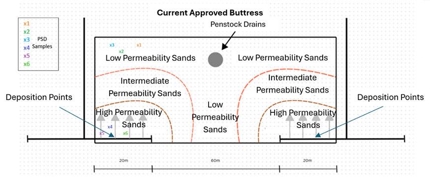
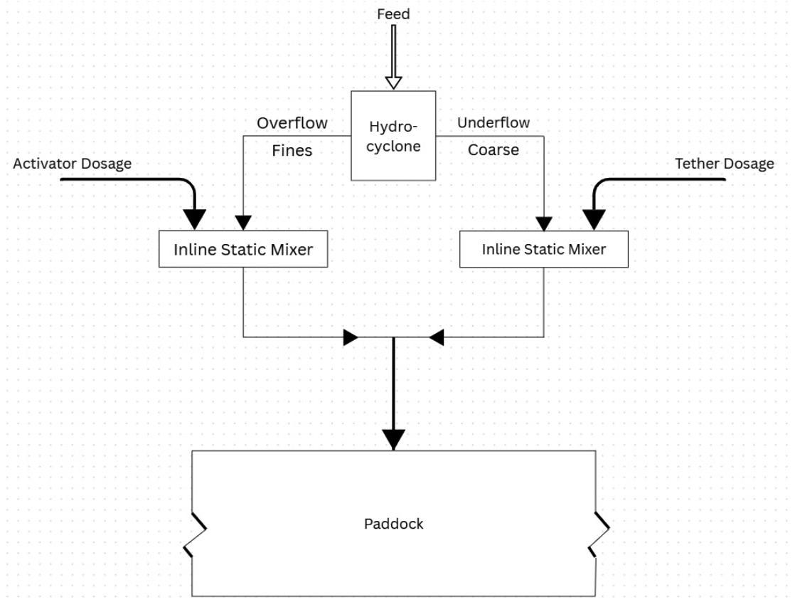
conditions of the St. Helena pilot plant
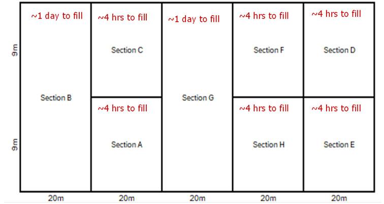
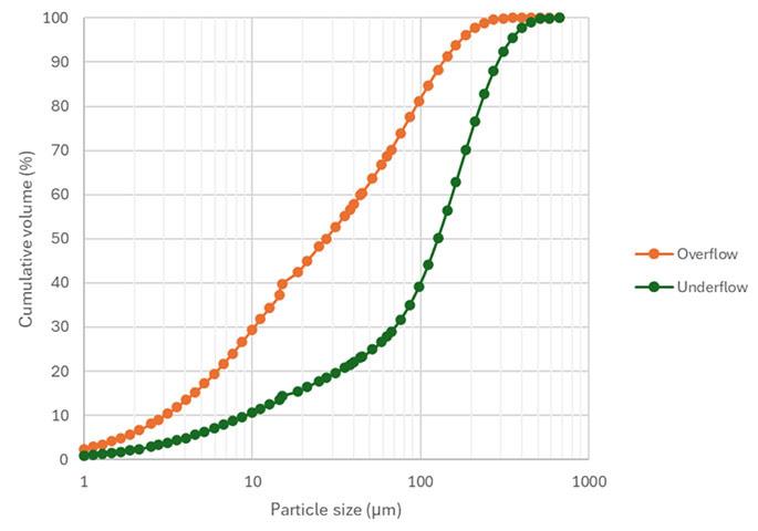
streams. The fine stream (cyclone overflow), with a flow of 6 t/h, was treated with the activator polymer in an inline mixer, and the coarse stream (cyclone underflow), with a flow of 3.8 t/h, was treated with the tether polymer in another inline mixer. Thereafter, the two streams were re-combined into a single pipe and deposited into the paddocks that form the buttress. The average PSD of the cyclone overflow and underflow can be seen in Figure 5.
The ATA® paddock was divided into eight different sections using woven geotextile bags, filled with ATA® treated material. This was done to accommodate the reduced capacity of the ATA® pilot plant (9.8 t/h) compared to the fill rate of the conventional buttress (21 t/h). The different sections can be seen in Figure 6. For simplicity and brevity, the paper will focus on the results from Sections A, B, and E.
Figure 3—Conventional buttress layout
Figure 4—Block flow diagram of ATA® system on site
Table 1
Figure 5—Particle size distribution of the cyclone overflow and underflow
Figure 6—ATA® buttress divided into eight sections
Improving tailings dewatering with ATA® for paddocked buttress formation: A pilot study
Sampling and analysis
The following tests were conducted on the samples collected from the different sections of the ATA buttress, as illustrated in Figure 6, in order to compare these properties to the samples collected from the conventional buttresses:
➤ Moisture content (SANS 3001-GR20:2010) (Civil Engineering Test methods. part GR20, determination of the moisture content by oven-drying, 2010)
➤ Turbidity (ISO 7027-1:2016) (Water quality — Determination of turbidity — Part 1: Quantitative methods, 2021)
➤ Particle size distribution (SANS 3001-GR1:2013) (Civil Engineering Test methods. part GR1, wet preparation and particle size analysis, 2013)
➤ Permeability (K.H. Head Method) (Head, Epps, 2011)
Moisture analysis
The samples were taken at varying timeframes after deposition and weighed immediately after collection to prevent any loss of moisture. The moisture content of each collected sample was measured by the gravimetric method, utilising oven drying at 110 ˚C for six hours.
Turbidity analysis
Slurry samples from the conventional buttressing method and ATA® treated method were collected in 20 L buckets at the deposition point. The samples were allowed to settle, and supernatant turbidity was measured at timed intervals. This provides an indication of the difference in settling velocity between the two buttressing methods. Supernatant water was sampled from each bucket and tested for turbidity using a Hanna HI98703 turbidity meter.
Particle size distribution (PSD)
Dried samples were screened to determine the PSD of the samples across the paddocks. Screen sizes of 75 µm, 106 µm, 150 µm, and 425 µm were used for the PSD analysis.
Permeability
Hydraulic conductivity, also known as soil permeability, measures how easily water can flow through the soil's pore spaces. This property is expressed by the permeability coefficient (k). The permeability tests were conducted using the triaxial permeability
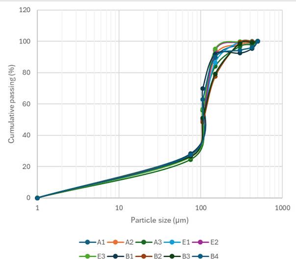
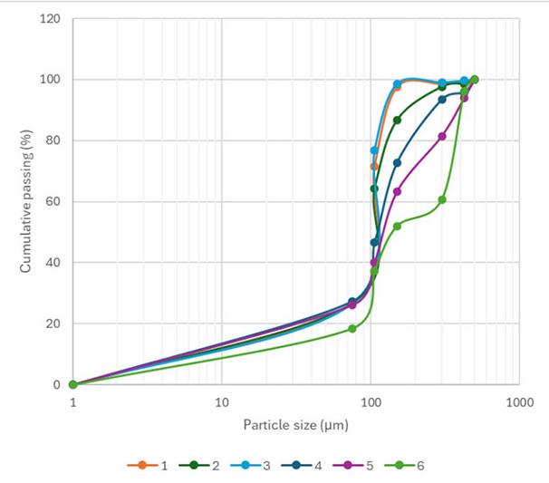
method (Head, Epps, 2011). This method is performed under a constant hydraulic gradient, utilising automated pressure controllers to regulate confining, inlet, and outlet pressures and to monitor volume changes.
Results and discussion
PSD homogeneity throughout the buttresses
Upon deposition of the conventional buttress, natural segregation of the coarse and fines material was observed from the deposition point to the drainage point in the buttress. To confirm this, PSD analyses were conducted on both the ATA® buttress and the conventional buttress. Figure 7 shows the PSDs for the three selected ATA® sections.
As seen in Figure 7, the PSD of the three ATA® sections are similar across the different sampling points. This shows homogeneity throughout the ATA® buttress and confirms the strength of particle-particle interaction between the fine and coarse material.
Figure 8 shows the PSD at six different sampling points in the conventional buttress, where sampling points 1 – 3 are further from deposition and sampling points 4 – 6 are closer to the deposition point.
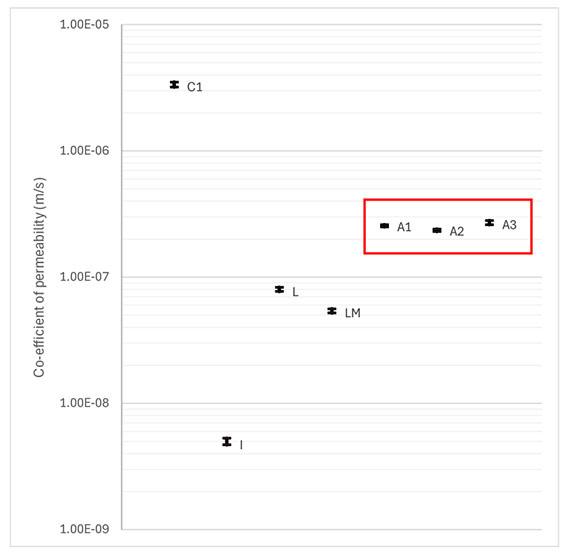
Figure 7—PSD of the three ATA® sections at different sampling points
Figure 8—PSD of six different sampling points in the conventional buttress
Figure 9—Permeability coefficient after deposition
Improving tailings dewatering with ATA® for paddocked buttress formation: A pilot study
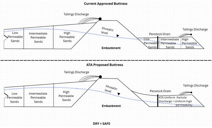
Figure 8 demonstrates a significant difference in PSDs between six different sampling points in the conventional buttress (see Figure 3). Coarser material was found in the area closest to the deposition point and finer material was found in the area sampled further away from the deposition point, as expected (see Figure 3). This shows that there are areas within the conventional buttress with relatively coarser PSDs and areas with relatively finer PSDs. Undisturbed samples from these different areas were used to test for a permeability difference between these areas, as low permeability areas within the buttress will reduce its ability to drain moisture and, therefore, its ability to support the dam efficiently.
Permeability of buttresses after deposition
As mentioned, undisturbed samples were taken for permeability testing from three areas in Section A of the ATA® buttress and from four areas in the conventional buttress, as shown in Error! Reference source not found. With reference to Figure 3, C1 refers to samples taken from the high permeability sands area, I refers to samples taken from the intermediate permeability sands area, L refers to samples taken from the low permeability sands area, and LM refers to samples taken from the low permeability sands area near the penstock drain.
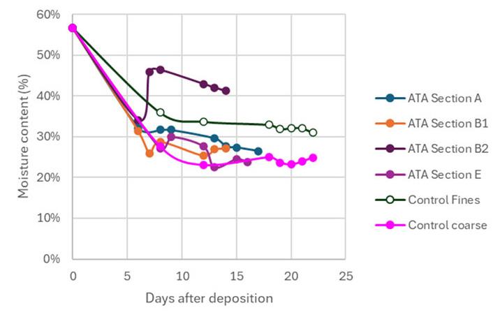
All ATA® samples exhibited higher permeability coefficients than the conventional buttress samples, with the exception of the coarse sample from the conventional buttress taken closest to the deposition point. This sample exhibits the highest permeability coefficient. The ATA® buttress samples exhibited consistency in permeability coefficients, which is indicative of the homogenous and granular nature of the ATA®-conditioned material across the entire buttress.
The conventional buttress samples show decreasing permeability coefficients with increasing distance from the deposition point. This, together with the PSD results, further indicates the occurrence of natural segregation within the buttress, with evident areas of high permeability sands (coarser PSD in Figure 8), areas of intermediate permeability sands, and areas of low permeability sands (Finer PSD in Figure 8). Low permeability areas within the buttress reduces its ability to drain water and therefore its ability to lower the dam’s phreatic line. Additional constructed drainage may be required in areas of low permeability in the conventional buttress; however, implementation of ATA could potentially eliminate the need for this supplementary drainage. Future monitoring studies of the phreatic surface are also recommended to verify the conceptual illustration presented in Figure 9.
Moisture content
Samples for moisture content analyses were taken periodically from the three sections in the ATA® buttress and compared to samples taken from the areas of coarse material and areas of fine material in the conventional buttress, as shown in Figure 4.
Figure 11 shows that ATA® Section A performed better than the fines area of the conventional buttress and is trending toward moisture results recorded for the coarse area of the conventional buttress. ATA® Section E achieved a lower moisture content than the fines area of the conventional buttress and reached the same moisture level as the coarse section of the conventional buttress after 13 days. The significant difference in moisture content between the control coarse and control fines in the conventional buttress further indicates that there is natural segregation of material occurring within the buttress, as the zones with coarser material drained more rapidly than those with the finer material.
Figure 10—Difference between ATA® and conventional buttressing expected phreatic lines due to permeability differences
Figure 11—Moisture content over time after deposition in the buttress
Improving tailings dewatering with ATA® for paddocked buttress formation: A pilot study
Table 2
Comparison of turbidity of supernatant after different settling durations for ATA and conventional deposition Treatment method Turbidity (NTU)
= not measured
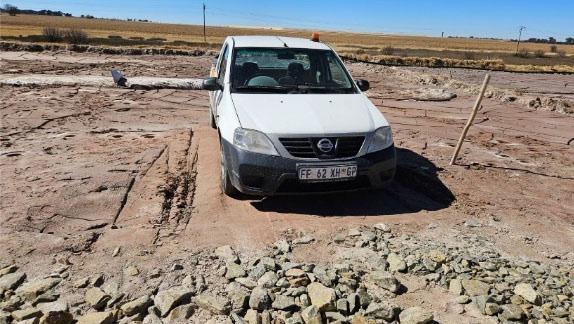
ATA® Section B was divided into two different categories. The samples of Section B1 were taken close to the outer wall of the buttress, away from the penstock drain. Section B2 samples were taken adjacent to the geotextile bags used for sectioning the ATA® buttress, closer to the penstock drain. There is an unusual spike in the moisture content in Section B2 due to water that is unable to drain through the geotextile bags used in this section of the paddock. The water that drained from Section B1 accumulated in Section B2. This indicates that the geotextile bags restricted drainage within the buttress and may not be suitable for this method of buttress construction at full-scale.
Trafficability was achieved after 13 days throughout the entire ATA® buttress (as seen in Figure 12) whereas, after the same duration, the fines area of the conventional buttress was still saturated and not trafficable. This demonstrates that the next layer of deposition can be placed sooner when ATA®-conditioning is used, compared to the current conventional buttressing method.
Turbidity
The turbidity of the supernatant water after varying settling durations is shown in Table 2. The supernatant turbidity of the ATA®-conditioned material was significantly lower than that of the conventional buttress material taken at the deposition point. Samples taken from the conventional buttress that were allowed to settle for up to 900 seconds were found to have excessive suspended solids, preventing measurement of the turbidity. This confirms that ATA® treatment’s rapid fines capture, re-capture, and settling rate are far greater when compared to the conventional buttress. This rapid settling resulted in cleaner and faster water drainage and improved water recovery, which could be returned to the site’s water circuit.
Conclusion
The results from this study show that ATA® leads to a more homogenous and potentially geotechnically stable buttress, compared to the conventional buttressing method. ATA®-treated material settles faster, without segregation. The agglomerate
structure formed is more permeable and allows for faster dewatering, leading to the buttress being trafficable sooner. Due to the decrease in segregation of ATA®-treated material, zones of low permeability were not observed. This results in more uniform drainage behaviour across the structure. This, in turn, lowers the phreatic line in the buttress, reduces moisture accumulation in the TSF wall, and enhances overall slope stability. Additionally, the rapid fines capture and accelerated dewatering achieved with ATA® improve water recovery efficiency, providing potential operational and environmental benefits through reduced water losses and shorter deposition cycles. Overall, ATA® conditioning results in a more consistent, rapidly dewatering and trafficable buttress, leading to increased TSF strength, improved operational efficiency, and safer tailings management.
References
Civil Engineering Test methods. part GR1, wet preparation and particle size analysis (2013). Pretoria: SABS Standards Division.
Civil Engineering Test methods. part GR20, determination of the moisture content by oven-drying (2010). Pretoria: SABS Standards Division.
Crous, P., Jacobsz, S. 2023. Geotechnical centrifuge modelling undrained triggers of tailings dam instability. The Southern African Institute of Mining and Metallurgy, [online] 1, pp. 24–25. Available at: https://www.saimm.co.za/Conferences/ files/tailings-2023/01%20577_Crous.pdf [Accessed 3 Sep. 2025].
Head, K.H., Epps, R. 2011. Manual of soil laboratory testing. volume 2, permeability, shear strength and compressibility tests. Caithness, Scotland, Boca Raton, FL: Whittles Pub.; CRC Press distributor, North America.
ICMM. 2020. Global industry Standard on Tailings Management. International Counsel on Mining and Metals, London.
ISO 7027-1:2016. 2021a. ISO. Available at: https://www.iso.org/ standard/62801.html (Accessed: 09 October 2025).
Lighthall, P.C., Watts, B.D., Rice, S. 1989. Deposition methods for construction of hydraulic fill tailings dams. In: Geotechnical Aspects of Tailings Disposal and Acid Mine Drainage. Vancouver, British Columbia: The Vancouver Geotechnical Society.
Spagnuolo, C., Fischmann, A.J., Sofra, F., De Kretzer, R., Cavilda, R., Brooks, E., Raath, J. 2024. ATA® treated tailings for underground backfill: a Harmony Gold case study. Paste 2024
Vick, S.G. 1990. Planning, design, and analysis of tailings dams Vancouver: BiTech. u
Figure 12—The ATA® buttress could support a vehicle being driven onto and off the buttress 13 days after deposition
NATIONAL & INTERNATIONAL ACTIVITIES
2026
25-29 May 2026 — SAIMM Pyrometallurgy International Conference 2026
Foundations of Competitiveness and Sustainability
CSIR International Convention Centre, South Africa
Contact: Gugu Charlie
Tel: 011 538-0238
E-mail: gugu@saimm.co.za
Website: http://www.saimm.co.za
24-25 June 2026 — Global Best Practices in Thickener and Dewatering Operations for Low-Grade and Complex Deposits Conference 2026
Introduce advanced solutions to improve thickener and filtration efficiencies amid changing ores
Southern Sun Rosebank, Johannesburg
Contact: Gugu Charlie Tel: 011 538-0238
E-mail: gugu@saimm.co.za
Website: http://www.saimm.co.za
7-8 July 2026 — SANIRE Symposium 2026
Balancing Judgement, Technology, and Sustainability in Rock Engineering Practices
Emperors Palace Convention Centre, Kempton Park
Contact: Gugu Charlie
Tel: 011 538-0238
E-mail: gugu@saimm.co.za
Website: http://www.saimm.co.za
30-31 July 2026 — Critical Minerals 2026 Conference From Potential To Prosperity – Building Africa’s Critical Minerals Value Chains Through Collaboration, Innovation and Governance
Royal Majestic Hotel, Rosebank, Johannesburg
Contact: Gugu Charlie Tel: 011 538-0238
E-mail: gugu@saimm.co.za
Website: http://www.saimm.co.za
18-20 August 2026 — CAVING 2026
Ulaanbaatar, Mongolia
Website: https://www.acgcaving.com/
18-21 August 2026 — SAIMM Uranium Conference 2026
Swakopmund Hotel and Entertainment Centre, Swakopmund, Namibia
Contact: Gugu Charlie Tel: 011 538-0238
E-mail: gugu@saimm.co.za
Website: http://www.saimm.co.za
26-27 August 2026 — ESGS Climate Change in Mining Conference 2026
Climate Change in Mining: Risks, Governance, Sustainability, and Environmental Management
Glenburn Lodge, Muldersdrift
Contact: Gugu Charlie
Tel: 011 538-0238
E-mail: gugu@saimm.co.za
Website: http://www.saimm.co.za
22-25 September 2026 — XIX International Society for Mine Surveying Congress 2026
Century City, Cape Town
Contact: Gugu Charlie Tel: 011 538-0238
E-mail: gugu@saimm.co.za
Website: http://www.saimm.co.za
7-11 September 2026 — Electra Mining Africa 2026
Expo Centre, Nasrec, Johannesburg
Contact: Gugu Charlie
Contact: Camielah Jardine
Tel: 011 538-0237
Website: http://www.saimm.co.za
21-24 September 2026 — XIX 2026 International Society for Mine Surveying Congress
Century City, Cape Town
Contact: Gugu Charlie
Tel: 011 538-0238
Website: http://www.saimm.co.za
29-30 September 2026 — 7TH Young Professionals Conference 2026
Mintek, Randburg, Johannesburg
Contact: Gugu Charlie
Tel: 011 538-0238
E-mail: gugu@saimm.co.za
Website: http://www.saimm.co.za
12-16 October 2026 — 19TH South African Geophysical Association Conference 2026
Lagoon Beach Hotel & Spa, Cape Town
Website: https://sagaconference.co.za/
18-22 October 2026 — IMPC 2026 XXXII International Mineral Processing Congress
Empowering a future-fit mineral processing industry
Cape Town, South Africa
Contact: Camielah Jardine
Tel: 011 538-0237
E-mail: camielah@saimm.co.za
Website: http://www.saimm.co.za
4-6 November 2026 — Southern African Mine Water Conference 2026
Let’s Connect
Glenburn Lodge, Muldersdrift
Contact: Gugu Charlie
Tel: 011 538-0238
E-mail: gugu@saimm.co.za
Website: http://www.saimm.co.za
Company affiliates
The following organizations have been admitted to the Institute as Company Affiliates
acQuire Technology Solutions
AECI Mining Chemicals, a division of AECI Mining Ltd
African Pegmatite
Allied Furnace Consultants
AMIRA International Africa (Pty) Ltd
Anglogold Ashanti Ltd
Anton Paar Southern Africa
Arcus Gibb (Pty) Ltd
Becker Mining (Pty) Ltd
Bluhm Burton Engineering (Pty) Ltd
Caledonia Mining South Africa
CARBOCRAFT (PTY) LTD
CIGroup ACE Pty Ltd
DDP Specialty Products South Africa (Pty) Ltd
Digby Wells and Associates
DQS Pty Ltd
EHL Consulting Engineers (Pty) Ltd
EKATO South Africa
Elbroc Mining Products (Pty) Ltd
Ex Mente Technologies (Pty) Ltd
Exxaro Resources Limited
FLSmidth Minerals (Pty) Ltd
G H H Mining Machines (Pty) Ltd
Geobrugg Southern Africa (Pty) Ltd
Glencore
Gravitas Minerals (Pty) Ltd
Hatch (Pty) Ltd
Herrenknecht AG
Impala Platinum Holdings Limited
IMS Engineering (Pty) Ltd
Ingwenya Mineral Processing
Ivanhoe Mines SA
Kelnir Projects (Pty) Ltd
M84 Geotech Pty Ltd
Malvern Panalytical (Pty) Ltd
Maptek (Pty) Ltd
Mech-Industries (Pty) Ltd
Micromine Africa (Pty) Ltd
Minerals Council of South Africa
MineRP Holding (Pty) Ltd
Mining Projection Concepts (Pty) Ltd
Mintek
MLB Investments CC
Modular Mining Systems Africa (Pty) Ltd
Murray & Roberts Cementation (Pty) Ltd
Paterson & Cooke Consulting Engineers (Pty) Ltd
Pump and Abrasion Technologies (PTY) Ltd
Redpath Mining (South Africa) (Pty) Ltd
Rosond (Pty) Ltd
Roytec Global (Pty) Ltd
Rustenburg Platinum Mines Limited - Union
Sebotka (Pty) Ltd
SENET (Pty) Ltd
Sibanye Gold Limited
Solenis
Sound Mining Solution (Pty) Ltd
SRK Consulting SA (Pty) Ltd
Sulzer Pumps (South Africa) (Pty) Ltd
Tomra (Pty) Ltd
Trans-Caledon Tunnel Authority
Ukwazi Mining Solutions (Pty) Ltd
Weir Minerals Africa
ZUTARI (Pty) Ltd
INTRODUCTION
One kilogram of uranium can produce as much energy as 160 tons of coal. As the world transitions to sustainable, low-carbon energy solutions, uranium will play an increasingly critical role by enabling the generation of large amounts of electricity with minimal greenhouse gas emissions. Uranium already forms part of a reliable and low-emission energy mix in many countries, contributing significantly to global decarbonisation efforts.
Uranium and nuclear energy has had its fair share of negative publicity, due to associations with nuclear weapons and the risk of wide-scale harm to humans and nature in the event of an accident. Despite these concerns, the benefits of nuclear energy makes uranium a compelling energy source.
Nuclear energy’s increasing momentum could be seen at COP28, where the first Global Stocktake under the Paris Agreement called for the acceleration of nuclear and other low-emission technologies to help achieve deep decarbonization.
This conference aims to bring together professionals from across the uranium value chain.
Topics will span the entire spectrum, from geology, mining, processing, application as nuclear fuel, application in the medical field, to post-mining closure – offering a holistic view of the uranium sector.
The conference will take place in the town of Swakopmund, Namibia – the heart of Namibia’s uranium mining industry. Swakopmund is a scenic coastal town, nestled between the Atlantic Ocean and the Namib Desert. It has much to offer the tourist, including great local cuisine, desert excursions, ocean activities and serene beach relaxation.
We invite students, lecturers, engineers, operators, economists, research and development professionals and policy makers to join in the conversations. Participants will gain a holistic view of the uranium industry and its multi-faceted role in modern society and the future of mankind.
CONFERENCE PROGRAMME
Papers are invited on the following topics:
• Uranium market trends
• Uranium resources, including exploration and new developments
• Mining
• Mineral and metallurgical processing
• Process control and optimization
• Analysis, including uranium and associated components
• Refining and value-added products
• Fuel cycle
• Recycling and reprocessing
• Nuclear/radioactive waste and site remediation
• Logistics of handling and transporting uranium in its various forms
• Medical applications
• Health and safety
• Environment, Social and Governance (ESG)
• Legislative and policy issues
• Economics
KEY DATES
• 23 March 2026 - Submission of abstracts
• 20 April 2026 - Submission of papers
• 18 August 2026 – Technical workshop: Modelling with Cycad Process
• 19-20 August 2026 - Conference
• 21 August 2026 - Technical visit: Langer Heinrich Uranium
CALL FOR PAPERS
Prospective authors are invited to submit titles and abstracts of their papers in English. The abstracts should be no longer than 500 words.
SUBMIT AN ABSTRACT
Acceptance of papers for publication in the SAIMM Journal will be subject to peer review by the Conference Committee and SAIMM Publications Committee pre-conference.
Gugu Charlie, Conferences and Events Coordinator FOR FURTHER INFORMATION, CONTACT:
E-mail: gugu@saimm.co.za
Tel: +27 11 538 0238
Web: www.saimm.co.za
ESGS CONFERENCE 2026 CLIMATE CHANGE IN MINING
Risks, Governance, Sustainability, and Environmental Management
DATE: 26-27 AUGUST 2026
VENUE: GLENBURN LODGE, MULDERSDRIFT

Building on the success of the inaugural 2025 event, the second ESGS Conference in 2026 will focus on the overarching theme of Climate Change in Mining. The conference will bring together mining leaders, policymakers, financiers, and sustainability experts to explore how the industry can adapt, innovate, and thrive in the face of climate challenges.
CONFERENCE THEMES AND TOPICS
Climate Risks for Mining Climate Governance and Finance
Mining faces increasing climate transitional and physical risks. This session will outline policy and regulatory guidance, modelling tools, and assessment approaches to identify the most critical risks and inform adaptation strategies.
Effective climate governance drives responsible action. Aligning with global agreements, meeting lender requirements, and leveraging sustainable finance are key to managing risks and unlocking opportunities. This session will highlight requirements and opportunities for South African mines and mining houses.
Sustainability Environmental Management
For mining to remain sustainable, it must transition to a low-carbon economy and adapt to climate change. This session will explore opportunities from circular economy principles, collective action, innovative technologies, and postmining transitions.
To minimise impact and adapt to climate change while maintaining compliance and social license to operate, mines must embrace environmental management. This session will unpack approaches to water and biodiversity management, systems thinking, and collaborative action.
Topics
Policy & Regulation, Modelling, Transitional Risk, Physical Risk, Building Resilience
Topics
Paris Agreements & Decarbonisation Targets, Lender Requirements, Finance Derisking, Carbon vs Sustainable Finance, MATA, GISTM
FOR FURTHER INFORMATION CONTACT:
Gugu Charlie, Conferences and Events Coordinator gugu@saimm.co.za
Tel: +27 11 538 0238
Topics
Circular Economy, Technology Innovation, Post-Mining Livelihoods & Just Transition, Collective Social Response
Topics: Water Stewardship, Biodiversity, Waste Management (including GISTM), EMS/Systems Thinking, Regional Collaborative Development