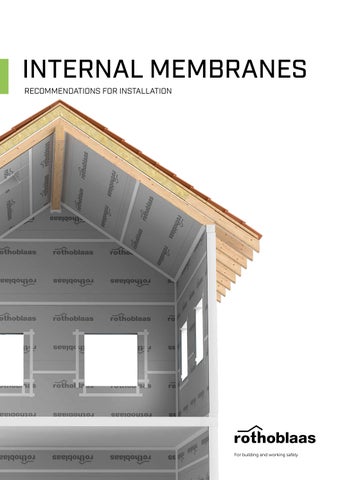
INTERNAL MEMBRANES RECOMMENDATIONS FOR INSTALLATION
INTERNAL MEMBRANES FIRE REQUIREMENTS BARRIER ALU NET SD1500 BARRIER ALU FIRE A2 SD2500
GREEN VAPOR IN GREEN 200
REFLECTIVE BARRIER ALU NET SD150 - BARRIER ALU NET SD1500 BARRIER ALU FIRE A2 SD2500
BLOWING BARRIER NET SD40 - BARRIER ALU NET SD150 BARRIER ALU NET SD1500 VAPOR NET 110 - VAPOR NET 180 - VAPOR IN NET 140 CLIMA CONTROL NET 145 - CLIMA CONTROL NET 160
BLOWING BARRIER NET SD40 - BARRIER ALU NET SD150 BARRIER ALU NET SD1500 VAPOR IN NET 140 - VAPOR NET 110 CLIMA CONTROL NET 145 - CLIMA CONTROL NET 160
FIRE REQUIREMENTS BARRIER ALU NET SD1500 BARRIER ALU FIRE A2 SD2500
VARIABLE Sd - RESTORATION CLIMA CONTROL 80 - CLIMA CONTROL 105 CLIMA CONTROL NET 145 - CLIMA CONTROL NET 160
THIS MANUAL IS APPLICABLE ON THE FOLLOWING CONSTRUCTION SYSTEMS:
CLT
TIMBER FRAME
Solid timber panels made by gluing layers of timber at right angles, with cross-laminated boards featuring orthogonal grain directions. The membrane is placed directly on the panel.
Lightweight construction system using vertical and horizontal low dimension’s timber members to form the building’s load-bearing structure. The membrane is placed directly on the structure.
MAXIMUM PROTECTION VAPOR EVO 190
TOPSIDE PROTECTION BARRIER ALU NET SD 1500 CLIMA CONTROL NET VAPOR 140 - VAPOR 150 - VAPOR NET 180 VAPOR EVO 190 - VAPOR 225
VARIABLE Sd - RESTORATION CLIMA CONTROL 80 - CLIMA CONTROL 105 CLIMA CONTROL NET 145 - CLIMA CONTROL NET 160
TRANSPARENT BARRIER NET SD40 - BARRIER SD150 CLIMA CONTROL 80 - CLIMA CONTROL 105 CLIMA CONTROL NET 145 VAPOR IN 120 - VAPOR IN NET 140
TRANSPARENT BARRIER NET SD40 - BARRIER SD150 VAPOR IN 120 - VAPOR IN NET 140 CLIMA CONTROL 80 - CLIMA CONTROL 105 CLIMA CONTROL NET 145
REFLECTIVE BARRIER ALU NET SD150 BARRIER ALU NET SD1500
WEATHER PROTECTION CLIMA CONTROL NET 160 VAPOR NET 110 - VAPOR 140 - VAPOR 150
CLADDING BOARDS
STEEL FRAMING
Frame walls or floors coated with materials like plywood, OSB, or plasterboard for stability and enclosure. The membrane is placed directly of the cladding board.
Lightweight construction system composed of low dimension’s steel or aluminium studs and tracks. The membrane is placed directly of the metal structure.
INTERNAL MEMBRANES | 3
AIRTIGHTNESS
RELATED PRODUCTS ALU BAND
DOUBLE BAND
REFLECTIVE SINGLE-SIDED ADHESIVE TAPE FOR INDOOR USE
UNIVERSAL DOUBLE-SIDED TAPE The solvent-free acrylic glue mix ensures excellent adhesion on most common supports, even at low temperatures. The membrane joint created with DOUBLE BAND recorded the highest tensile strength value following internal tests conducted with the best-performing tapes in the range.
The combination of glue and aluminium carrier makes it possible to achieve very high thermal stability without compromising the glue adhesion and viscosity.
HIGH TEMPERATURE
REFLECTIVE
INDOOR SEALING
HIGH ADHESION
BIADHESIVE
EASY BAND
SINGLE-SIDED TAPE FOR INDOOR USE
UNIVERSAL SINGLE-SIDED TAPE
The pre-shapeable carrier allows efficient and agile sealing of concave or convex corners and edges.
Progress adhesion, stable over time, for the most common supports. The adhesive, carrier and dimensions are also designed for prefabrication.
y
lo
on
INDOOR SEALING
w e m is
si
v er
PRE SHAPE
emis low
n sio
ver y
SEAL BAND
EASY USE
SPEEDY BAND
FLEXI BAND
UNIVERSAL SINGLE-SIDED TAPE WITHOUT RELEASE LINER
UNIVERSAL SINGLE-SIDED HIGH-ADHESIVE TAPE
Can be applied both internally and externally, guarantees fast and secure sealing on the most common materials.
The combination of carrier and acrylic dispersion glue is designed for good adhesion even in extremely cold temperatures.
EI 90
EI 90
CLT
CLT
SMART BAND
INVISI BAND
UNIVERSAL SINGLE-SIDED TAPE WITH SEPARABLE LINER
TRANSPARENT SINGLE-SIDED ADHESIVE TAPE WITHOUT LINER, RESISTANT TO UV AND HIGH TEMPERATURES
The product has a unique separating film which, thanks to a special treatment, can be divided at any point without pre-cutting, thus adapting to any installation requirement.
It is the water- and heat-resistant, transparent, liner-free, UV- and heat-resistant adhesive tape.
UV
EASY TEAR LINER
DURABILITY TESTED
FLASHING TAPE
4 | INTERNAL MEMBRANES | RELATED PRODUCTS
EI 90
CLT
NO LINER
HIGH ADHESION
SEE THROUGH
PLASTER BAND IN
MULTI BAND
SPECIAL HIGH-ADHESION TAPE, CAN BE PLASTERED
SPECIAL HIGH-ADHESION TAPE, CAN BE PLASTERED
Its excellent adhesion makes it ideal for application on most surfaces, even at low temperatures. Even when applied in tight spaces and corners, the PP liner can be removed without risk of failure.
Technical fabric ideal for subsequent plastering, ensuring an excellent aesthetic result by allowing the tape to be concealed behind cladding and plaster.
CAN BE PLASTERED
WINDOW SEALING
CAN BE PLASTERED
FUNCTIONAL FILM
NAIL PLASTER | GEMINI
NAIL BAND
HIGH-ADHESION NAIL SEALING TAPE
NAIL POINT SEALANT TAPE BUTYL
The closed cell polyethylene structure ensures the opening created by the fastening systems is waterproof. The product is resistant to heavy rain, confirming its efficacy and robustness in the most adverse conditions.
Thanks to its modified butyl formulation, it ensures excellent durability even when subjected to thermal stress. Also suitable for installation at low temperatures
HIGH STABILITY
UV
NAIL SEALING
MANICA PLASTER
MANICA FLEX
ADHESIVE SEALING SLEEVE THAT CAN BE PLASTERED
SEALING SLEEVE FOR CONDUIT AND CABLE PASSAGE
The butyl compound is covered with a polypropylene fabric that can be plastered. Thanks to its special modified butyl formulation, it ensures excellent durability even when subjected to thermal stress.
MANICA FLEX sealing sleeve ensures airtightness and watertightness for cables and other pass-through elements.
DURABILITY
NAIL SEALING
ELASTIC
ADAPTABLE
UV
EI 90
CLT
DURABILITY
LOW TEMPERATURE
CAN BE PLASTERED
HERMETIC CLOSURE
EASY USE
ACCESSORIES
PRIMER SPRAY
MARLIN
CUTTER
UNIVERSAL SPRAY PRIMER FOR ACRYLIC ADHESIVE TAPES
CUTTER ALLROUND
FOR PROFESSIONAL CUTTING
ROLLER
HAMMER STAPLER 47
HAMMER STAPLER 22
ROLLER FOR TAPES
HAMMER STAPLER
LARGE HAMMER STAPLER
RELATED PRODUCTS | INTERNAL MEMBRANES | 5
RECOMMENDATIONS FOR INSTALLATION
WALLS
This section describes the correct installation of internal membranes on walls, regardless of the construction system (CLT, timber frame, steel frame, or panel cladding).
GENERAL GUIDELINES: • • •
Plan the installation before starting. It’s important to have a clean worksite. Store the materials in their original packaging in a dry, fresh, ventilated and UV protected location.
• • •
Use the membrane on the internal side of the walls. Apply adequate tension to the membrane to ensure a correct adhesion of the sealing tapes. Avoid excessive tension to prevent damaging the membrane.
NOTES The membrane is shown over a white background to illustrate that the methodology can be applied to any of the previously mentioned construction typologies. SITE PREPARATION Clean the area, checking the surface for staples, nails, imperfections or other that might damage the membrane. Verify to have the required tools and materials.
1 MEASUREMENT Measure 1,5 m from the floor and mark the reference line for the top edge of the first membrane (the lower one).
1,5 m
2 INSTALLATION OF THE BOTTOM MEMBRANE Align the upper edge of the bottom membrane with the previously marked reference line. Fasten the top end of the membrane within the overlapping area. Apply 4–5 staples at the initial fastening point, making sure they are positioned in the overlap zone and oriented perpendicular to the direction of membrane tension, securing them to the timber structure. Discard membrane parts compromised during transport or construction.
3 6 | RECOMMENDATIONS FOR INSTALLATION | WALLS
For steel frame structure use DOUBLE BAND.
+
FIXING AND TENSIONING THE LOWER MEMBRANE – PHASE 1
1
Fasten the first point at the corner (1), then stretch the membrane and fasten the opposite corner (2). Proceed by fastening the central part of the bottom edge (3). The membrane should be evenly tensioned, adhering well to the wall, without wrinkles or folds, but also without excessive tension.
2
3
4 FIXING AND TENSIONING THE LOWER MEMBRANE – PHASE 2 Starting from the centre of the bottom edge (3), fasten the centre of the top edge (4). Tension the membrane and proceed with fixing the lower corners (5 and 6). Add extra staples to guarantee an adequate fastening of the membrane depending on the conditions of the project (type of insulation, timeframe, blower door test, etc).
4
6 3
5
5
FIXING AND TENSIONING THE UPPER MEMBRANE – PHASE 1 Placing the top membrane with a 100 - 150 mm overlap on the bottom membrane, covering the staples. Then fasten the lower corners (7–8) followed by the upper central section (9) using staples applied close to the edge of the timber structure, or adhesive tape if the structure is made of steel. Discard membrane parts compromised during transport or construction.
9
7 8
6 FIXING AND TENSIONING THE UPPER MEMBRANE – PHASE 1 From the centre of the upper edge (9), secure the lateral corners (10–11) and stretch the membrane downward to fasten the centre of the bottom edge (12). Add extra staples to ensure proper fastening, placing them perpendicular to the direction of membrane tension.
10 9 11
7
12
WALLS | RECOMMENDATIONS FOR INSTALLATION | 7
OVERLAP SEALING Once the membrane has been fastened, seal the joint using Rothoblaas adhesive tape or sealant. In both cases, use the ROLLER to ensure proper adhesion.
8 SEAL ALL ACCIDENTAL HOLES AND FASTENING SYSTEMS Ensure membrane continuity by covering fixings and any holes.
9 GROUND CONNECTION RECOMMENDATIONS The application surface must be clean, dry, and smooth to ensure proper adhesion of the Rothoblaas tape. If necessary, prepare the surface by applying PRIMER or PRIMER SPRAY before placing the tape.
10 CONNECTION TO THE GROUND Seal the gap between the membrane and the floor using tape with a minimum width of 100 mm. The tape must conform properly to corners and adhere uniformly, avoiding creases or bubbles that could compromise sealing or cause failure.
2
1
11 8 | RECOMMENDATIONS FOR INSTALLATION | WALLS
CORNER DETAIL – STEP 1 Make a 45° cut at the corners, creating two flaps to be fastened to the wall and the floor. Repeat the process on the opposite side.
12
45°
CORNER DETAIL – STEP 2 Apply the pre-cut and shaped 200 mm tape section to the corner, following the guidelines provided, to ensure airtightness.
13
OVERLAPPING For vertical surfaces, the minimum overlap must be 100 mm, as shown. For complex details, imperfect applications, spans longer than 10 m, or to ensure extra safety, a 150 mm overlap is recommended.
NOTES • • • •
Staples must be positioned at a safe distance from the edge to prevent tearing of the membrane. Rothoblaas tapes must be applied with adequate pressure using the ROLLER. Thoroughly clean the surface before applying PRIMER SPRAY. Permanent fastening: membranes must be fastened permanently using screws or nails that also secure internal elements (battens or panels). Staples or double-sided tape are temporary solutions, useful only to keep the membrane in place during application.
•
•
The fastening points of the counter-batten must be sealed using a continuous airtight system such as GEMINI, NAIL PLASTER, or NAIL BAND. The number of staples required may vary based on specific project parameters, such as exposure time, installation method, substrate material, membrane length, blower door test results, and other installation conditions. For standard timber frame applications, use one staple per stud; for panel and CLT systems, use one staple every 50 cm.
WALLS | RECOMMENDATIONS FOR INSTALLATION | 9
RECOMMENDATIONS FOR INSTALLATION
WINDOWS – INTERNAL SIDE THREE LEVELS OF PROTECTION
The three level method, which is used often in most European countries, identifies the airtightness, windtightness and thermal-acoustic insulation levels for proper placement of doors and windows. To obtain maximum performance, it is important to take care in all design stages and Rothoblaas offers specific solutions for each of the three levels.
THERMAL AND ACOUSTIC INSULATION LEVEL
WIND TIGHTNESS LEVEL
IN
IN
OUT
OUT
The most external level must guarantees protection against weather. If not properly developed, it can cause infiltration and water stagnation in the lower part of the window opening.
The intermediate level must guarantee thermal-acoustic performance and the mechanical fixing of the door/window frame. When selecting products, it is important to remember that an effective noise reduction solution does not always equate to good thermal insulation.
NOTES • • •
Special care must be taken to seal all points. Corners are critical areas and must be carefully checked to guarantee airtightness. When battens or other structures are installed over the membrane, airtightness must be ensured using NAIL PLASTER, GEMINI, or NAIL BAND.
AIRTIGHTNESS LEVEL
OUT
IN
•
The most internal level must be airtight. Its function is to prevent the passage of vapour laden air, which could create condensation in the joints and mould on the surface.
For more information on specific products and their characteristics, refer to the TAPES, MEMBRANES, SEALANTS AND FIRE PROTECTION catalogue.
The theory, in practice, is on YouTube When you need a deeper understanding of how and where to apply our products, a catalogue isn't enough. Installation instructions and practical tips for each field of application are available on our YouTube channel.
Follow our tips at: SUBSCRIBE
rothoblaas.com
10 | RECOMMENDATIONS FOR INSTALLATION | WINDOWS – INTERNAL SIDE
RECOMMENDATIONS FOR INSTALLATION
WINDOWS – INTERNAL SIDE
2
1 TOP EDGE PROTECTION
MEMBRANE PLACEMENT FOR THE WALL
To ensure airtightness in case of penetrations, a membrane strip or adhesive tape of suitable width must be applied to the top edge.
Position the membrane as described in the introduction section of this manual.
45°
4
3 MEMBRANE CUTTING
FASTENING THE SIDES TO THE WALL
In the area intended for window installation, make a cut slightly smaller than the frame. From this opening, cut diagonally towards the corners to form four flaps that can be folded.
Fold the membrane flaps towards the inner wall and fasten them using staples on timber supports or tape on steel structures. To improve airtightness at the corners, apply an additional strip of membrane.
6
5 CORNERS SEALING
CORNERS AND PERIMETER SEALING
Seal and finish the corners of the window taking care to cover all staples and overlapping membrane points.
Seal the pre-cut flaps and corners using tape, ensuring that all joints are completely covered. Close and finish the edges along the perimeter, making sure no gaps or open holes remain.
WINDOWS – INTERNAL SIDE | RECOMMENDATIONS FOR INSTALLATION | 11
RECOMMENDATIONS FOR INSTALLATION
ROOF - INTERNAL SIDE
Proper membrane installation on the inner side is essential to ensure airtightness and protect the insulation layer. Installation must be continuous between the wall and roof, with particular attention to corners and overlaps.
GENERAL GUIDELINES •
Follow the basic principles as described in the previous instructions (e.g. overlapping). Always seal staples and any membrane imperfections using Rothoblaas tape. To avoid breaking the membrane after installed, a fold like the image should be done on the corners. Secure the membrane permanently with timber battens fixed using screws or other suitable mechanical fasteners. Seal the fixing points of the counter-batten using NAIL PLASTER, GEMINI, or NAIL BAND.
• • •
1 USEFUL TIPS TO FACILITATE MEMBRANE INSTALLATION To ease installation, temporarily fix the membrane using DOUBLE BAND double-sided tape.
3
roof membrane tape
wall membrane
2 SEQUENCE FOR CORRECT TENSIONING DURING MEMBRANE INSTALLATION Position the membrane and press it onto the pre-applied DOUBLE BAND tape. Ensure airtightness by correctly overlapping the second layer of membrane.
4
MEMBRANE INSTALLATION WITH MECHANICAL FASTENING
EDGES AND CORNERS SEALING
When the membrane is placed, apply staples.
Finish the edges and corners of the membrane placing a sealing tape.
12 | RECOMMENDATIONS FOR INSTALLATION | ROOF - INTERNAL SIDE
RECOMMENDATIONS FOR INSTALLATION
ROOF WINDOWS - INTERNAL SIDE
Respect the 3 level-protection method (airtightness, thermal-acoustic and wind tightness).
THERMAL AND ACOUSTIC INSULATION LEVEL
WIND TIGHTNESS LEVEL
IN
IN
OUT
OUT
IN
OUT
1
AIRTIGHTNESS LEVEL
2
CUT THE CENTRE OF THE MEMBRANE IN THE WINDOW HOLE
CUT THE MEBRANE ON THE EDGE OF THE ROOF WINDOW
Using the MARLIN cutter to cut the centre of the membrane in the window hole.
Use a utility knife to trim the membrane in line with the top and bottom edges of the window.
3
4
Pay special attention to corners
FOLDING AND TAPING THE MEMBRANE EDGES
ENSURING AIRTIGHTNESS ALONG THE BOTTOM EDGE
Trim off excess membrane, fold the edges carefully, and seal them with Rothoblaas tape.
Apply a membrane strip to the lower section to cover the corners. Seal the bottom edge with tape to ensure airtight continuity around the window.
ROOF WINDOWS - INTERNAL SIDE | RECOMMENDATIONS FOR INSTALLATION | 13
RECOMMENDATIONS FOR INSTALLATION
ROOF WINDOWS - INTERNAL SIDE ENSURING AIRTIGHTNESS AT THE TOP SECTION Apply a membrane strip to the upper part to cover the top corners. Use tape to ensure airtight sealing along the top edge of the membrane around the window.
5 ENSURING AIRTIGHTNESS AROUND THE EDGES Use Rothoblaas tape to seal the edges of the membrane around the window perimeter and ensure airtightness.
6 CHECK THE THREE LEVELS OF PROTECTION Before sealing the window frame, apply WINDOW BAND, EXPAND BAND, or HERMETIC FOAM to ensure thermal and acoustic insulation.
7 POSITION AND SEAL THE WINDOW FRAME Seal the window frame hermetically using Rothoblaas tape to ensure continuous airtightness.
8 14 | RECOMMENDATIONS FOR INSTALLATION | ROOF WINDOWS - INTERNAL SIDE
RECOMMENDATIONS FOR INSTALLATION
INTERNAL WALL JUNCTIONS SITE PREPARATION Define the areas designated for internal partitions and ensure the site is clean before continuing.
1 INSTALL A TAPE OR MEMBRANE STRIP WHERE AN INTERNAL WALL IS PRESENT TO ENSURE THE CONTINUITY OF THE AIRTIGHTNESS LAYER To ensure continuity of the airtightness layer, install tape or a membrane strip on the internal side of the external wall where needed.
2
3
4
CONNECTION TO THE GROUND
POSITIONING OF THE INTERNAL WALL
Ensure airtightness at the bottom section using tape. If using a flexible tape like SEAL BAND, apply a 60 mm width; otherwise, use 100 mm tape. Recommendation: apply primer to prepare the surface.
Once sealing is complete, position the frame of the internal wall. In the presence of screws or other mechanical fasteners, apply nail sealing tapes to ensure airtightness.
NOTES • •
When connecting an internal wall to an external one, ensure the airtightness layer is continuous. Do not fold the membrane at the floor junction to avoid tearing during the installation of the internal wall.
•
Apply puncture-resistant sealing tape (e.g. nail sealing tape) behind the internal wall to protect the membrane from damage.
ROOF WINDOWS - INTERNAL SIDE | RECOMMENDATIONS FOR INSTALLATION | 15
RECOMMENDATIONS FOR INSTALLATION
SEALING OF PIPES AND CABLES
MANICA FLEX CUTTING THE MANICA FLEX Cut a piece of MANICA FLEX wide enough to cover the opening created by the passing pipe or cable.
1 CUTTING THE CORNER OF MANICA FLEX Fold the piece of MANICA FLEX into four parts and make a corner cut at the point where the pipe or cable will be inserted. The opening should be slightly smaller than the diameter of the pipe or cable to ensure an effective seal.
2
3 INSERTING THE PIPE OR CABLE After inserting the pipe or cable into the MANICA FLEX, close the edges of the sleeve with tape.
4
5 FINAL SEALING Complete the connection between the profile and the tape, and check the continuity of the sealing.
Seal the perimeter of MANICA FLEX with adhesive tape to finish the sealing of the hole.
6 16 | RECOMMENDATIONS FOR INSTALLATION | ROOF WINDOWS - INTERNAL SIDE
+
RECOMMENDATIONS FOR INSTALLATION
SEALING OF PIPES AND CABLES
MANICA PLASTER CUT AND PLACE MANICA PLASTER Clean and prepare the surface. Cut MANICA PLASTER according to the number of cables and the size of the penetration, and apply it as shown in the figure.
1 SEALING THE CABLE Remove the liner from the narrower end of MANICA PLASTER and press it carefully around the cable to close any gaps or openings.
2
Download the catalogue TAPES, MEMBRANES, SEALANTS AND FIRE PROTECTION The only element that protects you from the others
Via dell‘Adige N.2/1 | 39040, Cortaccia (BZ) | Italia Tel: +39 0471 81 84 00 | Fax: +39 0471 81 84 84 info@rothoblaas.com | www.rothoblaas.com
© Rothoblaas. All rights reserved. | 12/25 rev.01
ROTHO BLAAS SRL