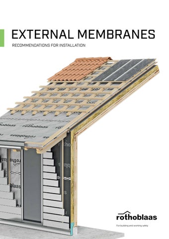
EXTERNAL MEMBRANES RECOMMENDATIONS FOR INSTALLATION
EXTERNAL MEMBRANES 1
MAXIMUM SAFETY MONOLITHIC MEMBRANES
1
ROOF | WALL TRASPIR EVO UV ADHESIVE - TRASPIR EVO 300 TRASPIR FELT EVO UV 210 -TRASPIR EVO SEAL 200 TRASPIR EVO 160 - TRASPIR EVO 135 ROOF TRASPIR WELD EVO 360 - TRASPIR DOUBLE EVO 340 - TRASPIR EVO 220
4
WALL TRASPIR EVO UV 210 - TRASPIR EVO UV 115
2
2
TROPICAL CLIMATES ROOF | WALL CLIMA CONTROL NET 160
3
10 12
3
SEALABLE ROOF TRASPIR WELD EVO 360
2
4 4
6
REFLECTIVE ROOF | WALL TRASPIR ALU FIRE A2 430 TRASPIR ALU 200 ONLY WALL TRASPIR ALU 120
1
7
10 5
OPEN JOINTS FAÇADE WALL TRASPIR EVO UV ADHESIVE - TRASPIR EVO 300 TRASPIR EVO UV 210 - TRASPIR FELT EVO UV 210 TRASPIR EVO UV 115
8 5
6
TRANSPARENT ROOF | WALL DEFENCE ADHESIVE TRASPIR
NOTES: The roof installation instructions also apply to BITUMINOUS UNDERLAY MEMBRANES: BYTUM 2000 - BYTUM 1500 - BYTUM 1100 - BYTUM 750 - BYTUM 400
MATERIALS CLT
TIMBER FRAME
CLADDING BOARDS
Solid timber panels made by gluing layers of timber at right angles, with cross-laminated boards featuring orthogonal grain directions. The membrane is placed directly on the panel.
Lightweight construction system using vertical and horizontal low dimension’s timber members to form the building’s load-bearing structure. The membrane is placed directly on the structure.
Frame walls or floors coated with materials like plywood, OSB, or plasterboard for stability and enclosure. The membrane is placed directly of the cladding board.
7
8 REDUCED EXPOSURE MICROPOROUS MEMBRANES
7
ROOF | WALL TRASPIR ADHESIVE 260 - TRASPIR ALU 200 TRASPIR 150 - TRASPIR 135 ROOF TRASPIR DOUBLE NET 270 - TRASPIR 200 TRASPIR NET 160 WALL TRASPIR ALU 120 - TRASPIR 110 - TRASPIR 95
9
METAL CLADDING
11
ROOF | WALL TRASPIR METAL
PUNCTURE RESISTANT ROOF | WALL TRASPIR EVO SEAL 200
8
9
12
ADHESIVE ROOF | WALL TRASPIR EVO UV ADHESIVE TRASPIR ADHESIVE DEFENCE ADHESIVE TRASPIR
VAPOUR CONTROL LAYER ON THE OUTER SIDE ROOF BARRIER ALU NET SD 1500 CLIMA CONTROL NET VAPOR 140 - VAPOR 150 - VAPOR NET 180 VAPOR EVO 190 - VAPOR 225
FIRE REQUIREMENTS ROOF | WALL TRASPIR ALU FIRE A2 430 TRASPIR EVO UV ADHESIVE - TRASPIR EVO 300 WALL TRASPIR EVO UV 210 - TRASPIR EVO UV 115
10
11
12
STEEL FRAMING
INSULATION LAYER
CONCRETE OR MASONRY
Lightweight construction system composed of low dimension’s steel or aluminium studs and tracks. The membrane is placed directly of the metal structure.
Applied to the exterior of the building envelope, it consists of rigid or semi-rigid panels to ensure thermal continuity and mechanical support. The membrane is applied directly to the surface of the insulation using staples or large-head nails.
Continuous structural element made of traditional materials, characterised by high mechanical strength and stability of the building envelope. The membrane is placed directly on the surface.
EXTERNAL MEMBRANES | 3
WIND TIGHTNESS
RELATED PRODUCTS FLEXI BAND UV
FACADE BAND UV
UNIVERSAL SINGLE-SIDED ADHESIVE TAPE WITH HIGH UV STABILITY AND TEMPERATURE RESISTANCE
UNIVERSAL SINGLE-SIDED TAPE, RESISTANT TO UV RAYS It is a universal tape with high UV stability, ideal for façade sealing and for overlapping on UV-ray resistant membranes.
FLEXI BAND UV universal tape provides high UV stability and heat resistance up to 120°C.
UV
DURABILITY TESTED
UV
HIGH TEMPERATURE
DURABILITY TESTED
HIGH/LOW TEMPERATURE
FLEXI BAND
SPEEDY BAND
UNIVERSAL SINGLE-SIDED HIGH-ADHESIVE TAPE
UNIVERSAL SINGLE-SIDED TAPE WITHOUT RELEASE LINER
The combination of carrier and acrylic dispersion glue is designed for good adhesion even in extremely cold temperatures.
Can be applied both internally and externally, guarantees fast and secure sealing on the most common materials.
UV
UV
UV
EI 90
CLT
DURABILITY TESTED
100% UV RESISTANCE
HIGH TEMPERATURE
EI 90
CLT
DURABILITY TESTED
MULTI BAND
MULTI BAND UV
SPECIAL HIGH-ADHESION TAPE, CAN BE PLASTERED
SPECIAL UV-RESISTANT HIGH-ADHESION TAPE
Technical fabric ideal for subsequent plastering, ensuring an excellent aesthetic result by allowing the tape to be concealed behind cladding and plaster.
Waterproof, multifunctional and soft, it is easy to apply and can be used in very different contexts, both in terms of climate and construction method.
CAN BE PLASTERED
B-s1,d0
NO LINER
EASY TEAR
CAN BE PLASTERED
DURABILITY
WINDOW SEALING
FUNCTIONAL FILM
UV
HIGH STABILITY
FRONT BAND UV 210
PLASTER BAND OUT
UNIVERSAL SINGLE-SIDED TAPE, HIGHLY RESISTANT TO UV RAYS
SPECIAL HIGH-ADHESION TAPE, CAN BE PLASTERED
It is the universal tape made of TRASPIR EVO UV 210 monolithic membrane that provides excellent aesthetic performance even in the most demanding architectural solutions.
Its excellent adhesion makes it ideal for application on most surfaces, even at low temperatures.
B-s1,d0
HIGH TEMPERATURE
4 | EXTERNAL MEMBRANES | RELATED PRODUCTS
CAMOUFLAGE
CAN BE PLASTERED
SMART BAND
INVISI BAND
UNIVERSAL SINGLE-SIDED TAPE WITH SEPARABLE LINER
TRANSPARENT SINGLE-SIDED TAPE WITHOUT RELEASE LINER, UV-RESISTANT
The product has a unique separating film which, thanks to a special treatment, can be divided at any point without pre-cutting, thus adapting to any installation requirement.
It is the water- and heat-resistant, transparent, liner-free, UV- and heat-resistant adhesive tape.
UV
EASY TEAR LINER
DURABILITY TESTED
FLASHING TAPE
EI 90
NO LINER
CLT
DOUBLE BAND
EASY BAND
UNIVERSAL DOUBLE-SIDED TAPE
UNIVERSAL SINGLE-SIDED TAPE
The solvent-free acrylic glue mix ensures excellent adhesion on most common supports, even at low temperatures. The membrane joint created with DOUBLE BAND recorded the highest tensile strength value following internal tests conducted with the best-performing tapes in the range.
Progress adhesion, stable over time, for the most common supports. The adhesive, carrier and dimensions are also designed for prefabrication.
HIGH ADHESION
EASY USE
BIADHESIVE
NAIL PLASTER | GEMINI
NAIL BAND
HIGH-ADHESION NAIL SEALING TAPE
NAIL POINT SEALANT TAPE BUTYL
The closed cell polyethylene structure ensures the opening created by the fastening systems is waterproof. The product is resistant to heavy rain, confirming its efficacy and robustness in the most adverse conditions.
HIGH ADHESION
SEE THROUGH
Thanks to its modified butyl formulation, it ensures excellent durability even when subjected to thermal stress. Also suitable for installation at low temperatures
UV
DURABILITY
NAIL SEALING
NAIL SEALING
MANICA PLASTER
MANICA FLEX
ADHESIVE SEALING SLEEVE THAT CAN BE PLASTERED
SEALING SLEEVE FOR CONDUIT AND CABLE PASSAGE
The butyl compound is covered with a polypropylene fabric that can be plastered. Thanks to its special modified butyl formulation, it ensures excellent durability even when subjected to thermal stress.
MANICA FLEX sealing sleeve ensures airtightness and watertightness for cables and other pass-through elements.
UV
EI 90
CLT
DURABILITY
LOW TEMPERATURE
CAN BE PLASTERED
EASY USE
HERMETIC CLOSURE
ELASTIC
ADAPTABLE
RELATED PRODUCTS | EXTERNAL MEMBRANES | 5
RECOMMENDATIONS FOR INSTALLATION
WALLS
This section describes the correct installation of external membranes on walls, regardless of the construction system (CLT, timber frame, steel frame, or external panel cladding).
GENERAL GUIDELINES:
•
• • •
•
Plan the installation before starting. It’s important to have a clean worksite. Store the materials in their original packaging in a dry, fresh, ventilated and UV protected location. Apply adequate tension to the membrane to ensure a correct adhesion of the sealing tapes. Avoid excessive tension to prevent damaging the membrane.
• •
•
Plan site activities to limit exposure to weather conditions, membrane degradation and stress on taped joints. Determine the number of staples according to the project conditions and expected loads; the values indicated are for guidance only. Refer to the CONSTRUCTION SITE, WATER AND DURABILITY Smartbook for correct membrane management on site.
NOTES The images show a CLT wall, but the installation instructions apply to any substrate.
SITE PREPARATION Clean the area and remove any dirt, staples or other imperfections that could damage the membrane. Verify to have the required tools and materials.
1 MEASUREMENT Measure 1,5 m from the floor and mark the reference line for the top edge of the first membrane (the lower one).
1,5 m
2
ON SITE, WATER CHANGES THE RULES Rain, standing water and unprotected details can alter the conditions defined at the design stage. With this Smartbook, we have translated onsite experience into technical criteria and workable solutions. Our experience is in your hands.
6 | RECOMMENDATIONS FOR INSTALLATION | WALLS
Download the SMARTBOOK
INSTALLATION OF THE BOTTOM MEMBRANE Align the upper edge of the bottom membrane with the previously marked reference line. Fasten the top end of the membrane within the overlapping area. Apply 4–5 staples at the initial fastening point, making sure they are positioned in the overlap zone and oriented perpendicular to the direction of membrane tension. Discard membrane parts compromised during transport or construction.
For steel frame structure use DOUBLE BAND.
3
For concrete structures, use a large-head hardened nail. Alternatively, if the surface is clean, temporarily secure the membrane with FLEXI BAND or DOUBLE BAND.
+
+
FIXING AND TENSIONING THE LOWER MEMBRANE – PHASE 1
2
1
Fasten the first point at the corner (1), then stretch the membrane and fasten the opposite corner (2). Proceed by fastening the central part of the bottom edge (3). The membrane should be evenly tensioned, adhering well to the wall, without wrinkles or folds, but also without excessive tension.
3
4 FIXING AND TENSIONING THE LOWER MEMBRANE – PHASE 2 Starting from the centre of the bottom edge (3), fasten the centre of the top edge (4). Tension the membrane and proceed with fixing the lower corners (5 and 6). Apply 2–3 staples at the main fastening points and add intermediate staples as required according to the project conditions (construction system, installation time, weather conditions, etc.).
4
3
5
5
6 For sealing of the ground connection, see page10
The number of staples must be determined according to the design and installation conditions, such as exposure time, installation method, weather conditions, substrate, membrane length and the pressure applied during the blower door test. For standard timber frame applications, use one staple per stud; on CLT panels, use one staple every 50 cm.
WALLS | RECOMMENDATIONS FOR INSTALLATION | 7
FIXING AND TENSIONING THE UPPER MEMBRANE – PHASE 1 Placing the top membrane with a 100 - 150 mm overlap on the bottom membrane, covering the staples. Then fasten the lower corners (7–8) followed by the upper central section (9) using staples applied close to the edge of the timber structure, or adhesive tape if the structure is made of steel. Discard membrane parts compromised during transport or construction.
9
7 8
6 FIXING AND TENSIONING THE UPPER MEMBRANE – PHASE 2 10 9
11
From the centre of the upper edge (9), secure the lateral corners (10–11) and stretch the membrane downward to fasten the centre of the bottom edge (12). Apply 2–3 staples at each main fastening point. Add further intermediate staples as required according to the specific project conditions (construction system, installation time, weather conditions, etc.).
12
7 OVERLAP SEALING OPTION 1 Once the membrane has been fastened, seal the joint using a Rothoblaas tape for outdoor applications. Use the ROLLER to ensure proper adhesion.
8.1
ROTHOBLAAS RECOMMENDS ROLLER
8.1.1 8 | RECOMMENDATIONS FOR INSTALLATION | WALLS
ROLLER FOR TAPES
OVERLAP SEALING OPTION 2 For membranes with integrated double tape, remove the release liner, press the upper membrane onto the adhesive and finish bonding with the ROLLER.
8.2 ROTHOBLAAS RECOMMENDS ROLLER ROLLER FOR TAPES
MARLIN CUTTER ALLROUND
CUTTER FOR PROFESSIONAL CUTTING
8.2.1
OVERLAP SEALING OPTION 3 For concealed sealing, where no integrated double tape is provided, DOUBLE BAND or Rothoblaas adhesives for external use may be used.
ROTHOBLAAS RECOMMENDS DOUBLE BAND UNIVERSAL DOUBLE-SIDED TAPE
8.3
TEMPORARY AND PERMANENT FASTENING Fastening with staples, adhesive tapes or nails must be regarded as temporary only. Provide permanent fastening using suitably-sized battens, properly anchored to the substrate, while ensuring an adequate ventilation cavity. Install the battens with a sealing system (NAIL PLASTER, GEMINI or NAIL BAND) to ensure airtightness and watertightness at the penetration points. For further details, see page 15.
WALLS | RECOMMENDATIONS FOR INSTALLATION | 9
RECOMMENDATIONS FOR INSTALLATION
BASE CONNECTIONS
The ground connection is one of the most critical points in the building. The solutions shown are examples and must be adapted to the specific project conditions. Membrane sealing must be determined according to the entire construction detail and its characteristics.
STRUCTURE ALIGNED WITH THE FOUNDATION
OUTDOOR
STRUCTURE SET BACK FROM THE FOUNDATION
INDOOR
OUTDOOR
Rothoblaas tape for windtightness
INDOOR
shaped insulation to turn up the waterproofing and prevent standing water
Rothoblaas tape for windtightness
PROTECT / GROUND BAND PLASTER BAND OUT
PROTECT / GROUND BAND
ROTHOBLAAS RECOMMENDS PROTECT
GROUND BAND
PLASTER BAND OUT
SELF-ADHESIVE BUTYL BAND, CAN BE PLASTERED
SELF-ADHESIVE BITUMINOUS MEMBRANE
SPECIAL HIGH-ADHESION TAPE, CAN BE PLASTERED
10 | RECOMMENDATIONS FOR INSTALLATION | BASE CONNECTIONS
RECOMMENDATIONS FOR INSTALLATION
WINDOWS – EXTERNAL SIDE THREE LEVELS OF PROTECTION
The three level method, which is used often in most European countries, identifies the airtightness, windtightness and thermal-acoustic insulation levels for proper placement of doors and windows. Window performance depends on the effectiveness of all three levels. Rothoblaas offers specific solutions for each one.
THERMAL AND ACOUSTIC INSULATION LEVEL
WIND TIGHTNESS LEVEL
IN
AIRTIGHTNESS LEVEL
IN
OUT
OUT
OUT
IN
The most external level must guarantees protection against weather. If not properly developed, it can cause infiltration and water stagnation in the lower part of the window opening.
The intermediate level must guarantee thermal-acoustic performance and the mechanical fixing of the door/window frame. When selecting products, it is important to remember that an effective noise reduction solution does not always equate to good thermal insulation.
NOTES • • •
Special care must be taken to seal all points. Corners require careful checking, as they are among the areas most prone to discontinuities in the seal. Use NAIL PLASTER, GEMINI or NAIL BAND at the fastening points of battens or other structures to maintain airtightness and watertightness.
•
The most internal level must be airtight. Its function is to prevent the passage of vapour laden air, which could create condensation in the joints and mould on the surface.
For more information on specific products and their characteristics, refer to the TAPES, MEMBRANES, SEALANTS AND FIRE PROTECTION catalogue.
The theory, in practice, is on YouTube When you need a deeper understanding of how and where to apply our products, a catalogue isn't enough. Installation instructions and practical tips for each field of application are available on our YouTube channel.
Find our tips at: REGISTER NOW
rothoblaas.com
WINDOWS – EXTERNAL SIDE | RECOMMENDATIONS FOR INSTALLATION | 11
RECOMMENDATIONS FOR INSTALLATION
WINDOWS – EXTERNAL SIDE
15 - 20 cm
1
2
SEALING THE TOP EDGE Before installing the membrane on the external side of the wall, install a strip of membrane along the top edge of the window opening to ensure windtightness.
REMOVING THE MEMBRANE AT OPENINGS Once the external membrane has been installed over the entire wall, cut it at the window opening, maintaining a distance of 15–20 cm between the cut and the edge of the opening.
45°
3 MEMBRANE CUTTING Make 45° cuts at the corners of the opening and complete the cut according to the dimensions of the window. Fold the membrane into the opening and seal it with Rothoblaas tape.
5 CHECK THAT THE MEMBRANE IS SECURELY FASTENED Check that the edges of the membrane are securely fastened. If necessary, secure the membrane with staples, positioning the latter close to the edge in the areas that will subsequently be sealed with tape.
4 SEALING THE BOTTOM EDGE Seal the bottom edge of the window with a strip of membrane and complete the sealing of the bottom corners.
6 SEALING THE EDGES Seal the edges of the membrane with weather-resistant tape. Use the ROLLER to improve the tape adhesion.
12 | RECOMMENDATIONS FOR INSTALLATION | WINDOWS - EXTERNAL SIDE
RECOMMENDATIONS FOR INSTALLATION
ROOF - INTERNAL SIDE
Correct installation of the membrane is essential to ensure windtightness and protect the insulation build-up. Installation must ensure continuity between the wall and the roof, with particular attention to corners and junctions.
GENERAL GUIDELINES •
external membranes
Follow the basic principles set out in the previous instructions (e.g. fastenings, taping and overlaps). Always seal staples and any membrane imperfections using Rothoblaas tape. Limit exposure to weather conditions and protect the membrane from mechanical damage, chemicals and heat sources. Permanently secure the membrane and provide ventilation using timber battens anchored with screws or other suitable fastening systems. Seal the fastening points of the battens using NAIL PLASTER, GEMINI, or NAIL BAND.
• • •
1
external membranes tape
tape tape external membranes
2
POSITIONING THE FIRST MEMBRANE
MEMBRANE FASTENING
Depending on the geometry and pitch of the roof, install the membrane starting from the lowest point, near the gutter or water outlet.
Following the tensioning sequence indicated for the wall, secure the membrane with staples or large-head nails. Where possible, position the fastenings within the overlap so that they are covered and sealed by the overlapping membrane. Avoid over-tensioning the membrane.
L = > 10 m
3 POSITIONING THE SECOND MEMBRANE
LONG ROOF SLOPES (> 10 m):
Position the second membrane, observing the recommended overlap: 10 cm for roofs with a pitch greater than 30°, 15 cm for membranes with integrated tapes and 20 cm for roofs with a pitch of less than 30°. The overlap dimensions are indicated directly on the membrane.
These increase the risk of the membrane sagging and require greater attention to the fastening system and taping
ROOF - INTERNAL SIDE | RECOMMENDATIONS FOR INSTALLATION | 13
4a
4b
4c
LONGITUDINAL OVERLAP – apply one of the following options 4a Membrane with double integrated tape: remove the release liner and use the ROLLER 4b Single-sided tape for external use: apply the tape over the overlap and use the ROLLER 4c Double-sided tape: apply it between the lower and upper membranes
TRANSVERSAL HEAD OVERLAPPING
8 - 10 cm 16 - 20 cm
1
2
PREPARE THE OVERLAP
CREATE THE OVERLAP FOLD
To create a transverse overlap, leave 16–20 cm of the lower membrane exposed to allow the upper membrane to overlap it.
Check the dimensions and lay out both membranes. Then fold the upper membrane over the lower membrane. The fold must be between 8 and 10 cm.
3
4
FOLD THE OVERLAP FOLD TOWARDS THE LOWER MEMBRANE
SEAL THE FOLD WITH TAPE
After checking the fold, make sure it is facing towards the lower membrane, i.e. the membrane installed first. Do not fold it towards the upper membrane, as this could compromise the watertightness of the overlap.
Seal the joint between the membranes with tape suitable for external use and for the roof pitch. Use the ROLLER to ensure proper adhesion.
14 | RECOMMENDATIONS FOR INSTALLATION | ROOF - INTERNAL SIDE
RECOMMENDATIONS FOR INSTALLATION
SEALING FASTENING SYSTEMS
NOTES •
Fastening with staples, adhesive tapes or nails must be regarded as temporary only. Provide permanent fastening using suitably-sized battens, properly anchored to the substrate, while ensuring an adequate ventilation cavity. The use of nail-point sealing tapes applied only at individual fastening points is not recommended, as any additional fastenings for photovoltaic systems or other finishes may not be sealed. The use of nail-point sealing tape is always recommended, as it increases the reliability of the roof's watertightness. In certain cases, as provided for by some national regulations, omission of the nail-sealing tape may be considered depending on the roof pitch, type of roof covering and the level of safety required for the building.
• •
OPTION 1 - GEMINI double-sided nail-sealing tape
1
2
APPLY THE NAIL-SEALING TAPE TO THE BATTEN
POSITION THE BATTEN AND SECURE THE TAPE
To ensure watertightness at the fastening points, use GEMINI, a double-sided nail-sealing tape applied to the batten before installation.
Position the batten. Once its correct position has been checked, remove the release liner from the tape and secure the batten. The fasteners passing through the batten are thereby sealed.
OPTION 2 - NAIL PLASTER or NAIL BAND single-sided nail-sealing tape
1
2
APPLY THE NAIL-SEALING TAPE TO THE MEMBRANE
POSITION THE BATTEN OVER THE TAPE
Apply the single-sided nail-sealing tape directly to the membrane, applying light pressure. Check that it is correctly positioned in relation to the batten before application, as the tape cannot be repositioned.
Once the nail-sealing tape has been installed, position the batten over the tape and secure it so that the fasteners pass through the tape itself, sealing the hole in the membrane.
SEALING FASTENING SYSTEMS – EXTERNAL SIDE | RECOMMENDATIONS FOR INSTALLATION | 15
ROOF WINDOW For roof windows too, continuity of installation must be ensured according to the three-level protection principle: airtightness on the internal side, thermal and acoustic insulation in the intermediate layer, and weathertightness on the external side. Roof window manufacturers generally also provide dedicated accessories and systems to ensure correct sealing. These systems allow the window to be effectively connected to the membrane installed on the roof. Alternatively, Rothoblaas products may be used.
Watch the dedicated video on sealing roof windows with Rothoblaas products. rothoblaas.com
ROTHOBLAAS RECOMMENDS MANICA FLEX SEALING SLEEVE FOR CONDUIT AND CABLE PASSAGE
Chemical sealing
Hot-air sealing
Tape sealing
FLEXI BAND UNIVERSAL SINGLE-SIDED HIGH-ADHESIVE TAPE
1
2
3
1
2
3
MANICA PLASTER ADHESIVE SEALING SLEEVE THAT CAN BE PLASTERED
16 | RECOMMENDATIONS FOR INSTALLATION | SEALING PIPES AND CABLES – EXTERNAL SIDE
BLACK BAND UNIVERSAL SINGLE-SIDED BUTYL TAPE
1
2
WELDING PIPE SLEEVE
Chemical sealing
Hot-air sealing
MANICA LEAD
MANICA POST
LEAD PROFILE WITH EPDM SLEEVE
ADHESIVE SEALING SLEEVE FOR OUTDOORS
MANICA SEALING SLEEVE WITH SHRINK TUBING AND CLAMP
Download the catalogue TAPES, MEMBRANES, SEALANTS AND FIRE PROTECTION The only element that protects you from the others
TUBE STOPPER CABLE SEALING PLUGS
Via dell‘Adige N.2/1 | 39040, Cortaccia (BZ) | Italia Tel: +39 0471 81 84 00 | Fax: +39 0471 81 84 84 info@rothoblaas.com | www.rothoblaas.com
The images are for product illustration purposes only; they may not fully reflect the product’s characteristics and may have been created using artificial intelligence systems.
© Rothoblaas. All rights reserved. | 09/26 rev.01
ROTHO BLAAS SRL