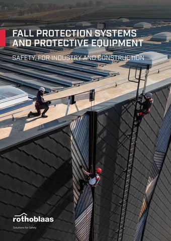
FALL PROTECTION SYSTEMS AND PROTECTIVE EQUIPMENT SAFETY, FOR INDUSTRY AND CONSTRUCTION
Solutions for Safety
LIFELINE AND RAIL SYSTEMS
27 WING
REWOT+LORTAP
ANCHOR POINTS
DILOS + LORTAP
HORIZONTAL LIFELINE
SINGLE POINTS
AOSWS
PATROL + TOWER.........................................30
103
CORNER
WING..............................................................104
PATROL + TOWER A2...................................32 AOSWS...........................................................106
PATROL + TOWER XL....................................34 PATROL+T-CLAMP
PATROL + SOLID............................................36
CLEVER
CORNER......................................................... 107 SOLID
PATROL + T-CLAMP.....................................38 PATROL+SHIELD 2
C-LEVER.........................................................108
PATROL + SHIELD | SHIELD 2.....................40 PATROL + WAVE............................................42
LOOP
SOLID.............................................................. 110 HOOKHOOK
PATROL + COPPO.........................................44
LOOP.............................................................. 112
PATROL+BLOCK
PATROL + T-ROOF........................................46
HOOKEVO 2.0
HOOK SPIKE................................................. 113
PATROL + BLOCK..........................................48
MILS
PATROL OVERHEAD
PATROL + PATROLEND................................50
KITE
PATROL OVERHEAD.....................................52 PATROL
HOOK EVO.................................................... 114 HOOK EVO 2.0............................................. 115 SLIM................................................................. 116
PATROL ON WALL.........................................54 KITE................................................................. 117
PATROL | components.................................56
AOS
SIANK.............................................................. 118 H-RAIL over BULLONE H-RAIL on wall BULLONE
HORIZONTAL AND VERTICAL RAIL
AOS................................................................. 119
H-RAIL OVERHEAD.......................................62 H-RAIL ON WALL...........................................64 vertical
AOS01 + TOWER/TOWER A2....................120
H-RAIL + SOLID.............................................66
AOS01 + TOWER XL.................................... 121
H-RAIL + TOWER...........................................68
PMALCT + SOA
H-RAIL ON FLOOR........................................70 vertical VERTIGRIP ON LADDER
H-RAIL VERTICAL.......................................... 72
10SOA +0.2 dleihS
AOS01 + T-CLAMP......................................122
H-RAIL | combinations................................. 74 AOS01 + SHIELD..........................................123
H-RAIL | components................................... 76
AOS01 + SHIELD 2.......................................124 AOS01 + WAVE.............................................125
VERTICAL LIFELINE VERTIGRIP ON LADDER...............................84
AOS01 + COPPO.........................................126
VERTIGRIP ON WALL....................................86 VERTIGRIP | combinations..........................88 VERTIGRIP | components............................90
GREEN POINT
AOS01 + BLOCK........................................... 127
GREEN LINE
GREEN ROOF LIFELINE
GREEN POINT..............................................128
GREEN LINE....................................................94
MOBILE
GLUE ANCHOR............................................129
GREEN LINE | components.........................96 TEMPORARY
TEMPORARY LIFELINE TEMPORARY...................................................98 HOLD-SYSTEM®...........................................99
RAPTOR
MOBILE..........................................................130 ROD................................................................. 131 CARRIER...........................................................56 RAPTOR.........................................................133
COLLECTIVE PROTECTION GUARD W
137
PERMANENT RAILING BARRIERS
PERSONAL PROTECTIVE EQUIPMENT imbracature
caschi
HELMETS from page .....................................................180
BORDER W....................................................140
anticaduta e posizionamento
BORDER V/BORDER VD............................. 141
HARNESSES
BORDER H..................................................... 142 BORDER M.................................................... 143
step up
179
from page .....................................................184 dispositivi retrattili
BORDER Z......................................................144
FALL PROTECTION AND POSITIONING
BORDER | components.............................. 145
from page ..................................................... 193
RETRACTABLE DEVICES from page ..................................................... 197 dispositivi retrattili
FIXED LADDERS STEP UP..........................................................150
ancoraggi
KIT from page .....................................................198
STEP UP | components.............................. 152
TEMPORARY ANCHOR SYSTEMS connettori
PITCHED LADDERS
corde e accessori
from page .................................................... 200
CONNECTORS from page .................................................... 202
EASY LAD.......................................................158
DISCENSORI-AUTOBLOCCANTI
ROPES AND ACCESSORIES
EASY WALK
from page .................................................... 206
WALKWAYS AND OVERPASSES ALL WALK.......................................................160
tripodi e gru
DESCENDERS AND CLAMPS from page .................................................... 208
EASY WALK....................................................162
TRIPODS AND CRANES from page .....................................................210
SAFENET
PERMANENT FALL PROTECTION NET
accessori
OVERNET.......................................................164 ROLLNET.......................................................166
RESCUE from page .....................................................215
ACCESSORIES from page .....................................................216
HORIZONTAL NET
TEMPORARY FALL PROTECTION NETS HORIZONTAL NET.......................................168 VERTICAL NET.............................................. 170 FRAME NET....................................................171
COMPLEMENTARY PRODUCTS
227
ATTREZZATURA
EDGETEMP 2
TEMPORARY RAILING BARRIERS
TOOLS
EDGE TEMP 1................................................ 172
from page .................................................... 230
EDGE TEMP 2............................................... 172
ACCESSORI
EDGE TEMP 3............................................... 173
MACHINES from page .....................................................242
EDGE TEMP 4............................................... 173
ACCESSORIES
HANGROOF
CALCESTRUZZO
from page .................................................... 246
LADDER HOOKS FASTENING ON CONCRETE
HANG TEMP.................................................. 174
from page .................................................... 256
HANG ROOF................................................. 174 HANG WALL.................................................. 175
FASTENING ON TIMBER
HANG PLAIN................................................. 175
from page .................................................... 264 BARRE
THREADED RODS, WASHERS, NUTS AND BOLTS from page .................................................... 269
THE HIERARCHY OF FALL PROTECTION
1
ELIMINATE THE RISK
Where possible, avoid work at height. Alternatively, install systems and equipment in safe areas free from the risk of falls.
2
COLLECTIVE PROTECTION
If work at a height is unavoidable, minimise the risk of falls by using collective protection such as the Rothoblaas BORDER railing, and avoid unnecessary exposure.
3
PERSONAL PROTECTION
Where the risk of falls cannot be eliminated, use a suitable safety system to minimise the consequences, employing restraint or fall protection systems.
6 | THE HIERARCHY OF FALL PROTECTION
B-SAFE, online too B-SAFE is the new Rothoblaas platform that lets you design complete fall protection solutions online with ease. With a suite of advanced tools, you can: • Customise and optimise projects to meet all needs. • Manage installation and inspection documentation quickly and accurately. • Calculate loads and deflections to ensure maximum safety. B-SAFE: a single, user-friendly platform, available anytime.
Design with us at b-safe.rothoblaas.com rothoblaas.com
WORK METHODS RESTRAINT A personal protection system that prevents the worker from reaching areas at risk of falls from height, keeping them in a safe position by means of devices that limit movement.
POSITIONING AT WORK This allows the person to work in tension or restraint, keeping them in a stable and safe position, thus preventing falls. The worker is supported by personal protective equipment such as harnesses and ropes that ensure safety and stability during work. ©Høyden
posizionamento
ROPE ACCESS The worker safely accesses and moves towards the area of work using a work rope and a safety rope, each separately connected to secure anchor points. The system allows safe operation in hard-to-reach areas, such as vertical walls or elevated surfaces, preventing or stopping falls.
posizionamento
FALL ARREST A protection system that immediately stops a worker, limiting the impact force on their body during the arrest. It consists of devices such as harnesses, ropes and anchors, distributing the impact energy in a controlled manner.
© Høyden
RECOVERY OR RESCUE The set of procedures necessary to assist and safely recover a worker in an emergency situation, such as a fall or illness, during work at height. These operations allow a person to save themselves or others using specific equipment and applying rapid response protocols.
8 | WORK METHODS
RISK OF FALLING FROM HEIGHT VERTICAL CLEARANCE When working in fall protection, the VERTICAL CLEARANCE must be taken into account: TA = LC + Lmax + HA + DSIC
[m]
TA
vertical clearance
LC
LC
length of rope/device between the permanent anchor point and harness anchor point
Lmax TA
Lmax maximum extension of the energy absorber (maximum 1,75 m) HA
1.50 m average height above the operator's feet from the anchor point of the harness
HA
DSIC safety distance (minimum 1 m)
DSIC
FALL FACTOR The FALL FACTOR expresses the degree of danger of a fall: FC = H / L FC
fall factor
H
height fallen during the fall
L
length of the rope / connection device
2 > FC > 0 where FC = 2 is the maximum fall factor Minimal risk of harm to the operator’s body Risk of harm to the operator’s body High risk of harm to the operator’s body FC = 0
FC = 1
FC = 2
without energy absorber with energy absorber
PENDULUM EFFECT The "pendulum effect" refers to a lateral movement that occurs during a fall when the anchor is not located vertically with respect to the worker. This can be a dangerous situation as it may cause the operator to collide with obstacles along the fall trajectory. How to prevent the pendulum effect? 1. Plan the work and analyse the risk of falls 2. Position the anchor vertically above the operator 3. Use appropriate Personal Protective Equipment (PPE)
RISK OF FALLING FROM HEIGHT | 9
WORK CONTEXTS
CONFINED SPACES CONSTRUCTION SITE posizionamento
FAÇADE posizionamento
AERIAL WORK posizionamento PLATFORM
VERTICAL ACCESSES posizionamento
10 | WORK CONTEXTS
posizionamento PYLONS
posizionamento PITCHED ROOF
posizionamento INDUSTRIES
FLAT ROOF posizionamento
WORK CONTEXTS | 11
FAÇADE FAÇADE ACCESS AND MAINTENANCE
PERMANENT ANCHOR POINTS
PATROL
WING
SOLID
H-RAIL
C-LEVER
HORIZONTAL LIFELINE
ANCHOR POINT FOR ROPE ACCESS WORK
RIGID ANCHOR POINT FOR ROPE ACCESS WORK
RAIL SYSTEM FOR HORIZONTAL AND VERTICAL USE
DIVERSION SYSTEM FOR ROPE ACCESS AND FAÇADE WORK
page 28
12 | WORK CONTEXTS
page 104
page 110
page 60
page 30
PPE
HERO
OLYMPIA
TOOLGRAB
EDGEPRO
PLANK
HELMET FOR WORK AT HEIGHT, ON CONSTRUCTION SITES OR IN INDUSTRIAL AREAS
FULL PROFESSIONAL HARNESS FOR ROPE ACCESS WORK
FALL PROTECTION FOR TOOLS
LIGHT ALUMINIUM ALLOY ROLLER FOR ROPE MOVEMENT
SEAT FOR EXTENDED SUSPENSION WORK
page 180
page 184
page 216
page 207
page 192
WORK CONTEXTS | 13
INDUSTRIAL AND RESIDENTIAL ROOFS WORK ON FLAT AND PITCHED ROOFS
COLLECTIVE PROTECTION
PERMANENT ANCHOR POINTS
BORDER
OVERNET
EASY WALK
PATROL
ANCHOR POINTS
ALUMINIUM PERMANENT AND TEMPORARY RAILINGS
PERMANENT FALL PROTECTION SYSTEM
WALKWAYS SYSTEMS FOR TRAPEZOIDAL METAL SHEET ROOFS
HORIZONTAL LIFELINE
see the full range of products
page 138
14 | WORK CONTEXTS
page 164
page 162
page 28
page 104
PPE
HERO
HARNESSES
DOUBLE SICUROPE
ROPE 1
BACK
HELMET FOR WORK AT HEIGHT, ON CONSTRUCTION SITES OR IN INDUSTRIAL AREAS
see the full range of products
DOUBLE ARM ROPE WITH ENERGY ABSORBER
SEMI-STATIC ROPE WITH SEWN ENDS AND AUTOMATIC CARABINER
FALL ARRESTER
page 180
page 184
page 193
page 195
page 196
WORK CONTEXTS | 15
VERTICAL ACCESSES AND WALKWAYS PYLONS / SILOS / ROOFS / WIND TURBINES / AERIAL LIFTS
COLLECTIVE PROTECTION
ANCHOR SYSTEMS
STEP UP
ALL WALK
VERTIGRIP
H-RAIL
TRI
CAGED LADDERS
WALKWAYS AND OVERPASSES
VERTICAL LIFELINE
RAIL SYSTEM FOR HORIZONTAL AND VERTICAL USE
MOBILE DEVICE WITH THREE FEET FOR LOWERING, LIFTING AND RECOVERY
page 150
16 | WORK CONTEXTS
page 160
page 82
page 60
page 210
PPE
HERO
SPARTA
ROPE 1
BACK
TOOLGRAB
HELMET FOR WORK AT HEIGHT, ON CONSTRUCTION SITES OR IN INDUSTRIAL AREAS
COMPLETE PROFESSIONAL HARNESS
SEMI-STATIC ROPE WITH SEWN ENDS AND AUTOMATIC CARABINER
FALL ARRESTER
FALL PROTECTION FOR TOOLS
page 180
page 186
page 195
page 196
page 216
WORK CONTEXTS | 17
INDUSTRIES WORK ON MACHINERY, AUTOMATIC WAREHOUSES, OVERHEAD CRANES, VEHICLE LOADING/UNLOADING
COLLECTIVE PROTECTION
PPE
BORDER
STEP UP
HERO
HARNESSES
FALL BLOCK
ALUMINIUM PERMANENT AND TEMPORARY RAILINGS
CAGED LADDERS
HELMET FOR WORK AT HEIGHT, ON CONSTRUCTION SITES OR IN INDUSTRIAL AREAS
see the full range of products
RETRACTABLE DEVICE WITH STEEL CABLE
page 138
18 | WORK CONTEXTS
page 150
page 180
page 184
page 197
PERMANENT ANCHOR POINTS
PATROL
H-RAIL
VERTIGRIP
KITE
CARRIER
HORIZONTAL LIFELINE
RAIL SYSTEM FOR HORIZONTAL AND VERTICAL USE
VERTICAL LIFELINE
ANCHOR POINT
SLIDING ANCHOR FOR STEEL STRUCTURES
page 28
page 60
page 82
page 117
page 56
WORK CONTEXTS | 19
CONSTRUCTION SITE TEMPORARY COLLECTIVE PROTECTION FOR CONSTRUCTION SITES
COLLECTIVE PROTECTION
ANCHOR SYSTEMS
VERTICAL NET
HORIZONTAL NET
FRAME NET
KITE
ROD
VERTICAL POLYPROPYLENE FALL PROTECTION SAFETY NET
HORIZONTAL POLYPROPYLENE FALL PROTECTION SAFETY NET
FALL PROTECTION SAFETY NET WITH FRAME
ANCHOR POINT
ANCHOR POINT FOR STEEL STRUCTURES
page 170
20 | WORK CONTEXTS
page 168
page 171
page 117
page 131
PPE
HELMETS
HARNESSES
HOLD-SYSTEM®
STRAP
SCAFFOLD DUO
see the full range of products
see the full range of products
TEMPORARY HORIZONTAL ANCHORING DEVICE
RETRACTABLE DEVICE
DOUBLE ARM ROPE WITH ENERGY ABSORBER
page 180
page 184
page 99
page 197
page 193
WORK CONTEXTS | 21
PRODUCT From the background of construction products to EN 17235 ready
For over 30 years, Rothoblaas has pioneered innovation in the construction market with solutions for timber and hybrid structures as well as safety, offering cutting-edge products for the building and industrial sectors.
Y
EN
235 17
READ
SAFE EVERYWHERE
GRAVITY LAB & SAFE C.LAB
Our products and systems comply with the latest and most widely adopted regulations and are designed according to the most advanced technological standards.
We perform product tests in our in-house laboratory. The certifications are issued by third-party organisations.
CSA
EN
ANSI OSHA
AS/ NZS
anchor points
machinery directive
personal protective equipment (PPE)
construction products CPR
B-SAFE
COMPLETE SOLUTIONS
PRODUCT DEVELOPMENT
Our products are supplied complete with all the necessary documentation.
All stages of development and testing for our products are managed in-house.
BIM
declaration of conformity
•
certificate
•
installation manual
•
safety regulations
prototype development prototype production and testing
concept and feasibility study EN 17
5 23
5 23
design
tests and certifications
EN 17
•
production
market launch
EN 1 EN 177
535 232
EN 17
5 23
EN 17
5 23
DURABILITY & SUSTAINABILITY Made primarily from steel and aluminium, our products are durable with a very low environmental impact.
TOP QU
DESIGN TO LAST TY ALI
22 | PRODUCT
When used correctly and regularly inspected, our products can have a lifespan equivalent to the service life of the building.
DESIGNED TO REDUCE THEIR IMPACT
REDUCED
SUSTAINABLE
SUPPORT B-SAFE CONFIGURATOR The multifunctional Rothoblaas portal allows: •
Project configuration complete with fall protection solutions
•
Calculation of loads and deflections
•
Management of installation and servicing documentation
INSTALLATION VIDEO Assembly instructions for our fall protection system can be found on our YouTube channel.
ONLINE RESOURCES •
Building Information Modelling (BIM) on ProLib
•
CAD files and specification items available on our website
SERVICES AND TRAINING TECHNICAL CONSULTANCY Dedicated support for engineers, technicians and installers on the positioning and correct choice of fastening systems. A personalised consultation for each stage of the design, development and maintenance of our systems.
ROTHOSCHOOL In-person and online training courses for fall protection system installers with the “Safety Learning” program.
ROTHOSCHOOL ON TOUR We bring “SAFETY” courses closer to you. Learn more on our website.
Discover our in-person or online offering with the “Safety Learning” program www.rothoblaas.com/school
SUPPORT | 23
LIFELINE LIFE AND LINE RAIL SYSTEM SYSTEMS
HORIZONTAL LIFELINE
LIFELINE AND RAIL SYSTEMS
PATROL + TOWER
PATROL + TOWER A2
page 30
PATROL + T-CLAMP
PATROL + SHIELD | SHIELD 2
page 38
page 40
PVC
PATROL + T-ROOF
PATROL + TOWER XL
page 32
TPO
PATROL ON WALL page 54
26 | LIFELINE AND RAIL SYSTEMS
PATROL + WAVE
PATROL + SOLID page 36
PATROL + COPPO page 42
page 44
BYTUM
PATROL + BLOCK
page 46
page 34
page 48
PATROL + PATROLEND page 50
PATROL OVERHEAD page 52
H-RAIL ON WALL
page 62
H-RAIL + SOLID
page 64
HORIZONTAL AND VERTICAL RAIL
H-RAIL OVERHEAD
H-RAIL + TOWER page 66
H-RAIL ON FLOOR
H-RAIL VERTICAL page 72
VERTICAL LIFELINE
TEMPORARY LIFELINE
page 70
page 68
TEMPORARY
GREEN ROOF LIFELINE
page 98
GREEN LINE
HOLD-SYSTEM® page 94
VERTIGRIP ON WALL page 99
page 86
VERTIGRIP ON LADDER page 84
LIFELINE AND RAIL SYSTEMS | 27
PATROL
HORIZONTAL LIFELINE
MODULAR, SIMPLE, SAFE SYSTEM. With our PATROL LIFELINE system, horizontal, overhead or façade lifelines, both through and overhead, are child's play. Thanks to dedicated supports, the system can be quickly installed on timber, metal or concrete substrates. Furthermore, a wide range of specific accessories ensures all your design needs can be easily met.
SLIDING DEVICE SLIDE1
SLIDE1 A4
SLIDE2
+
+
+
A2
material
certification
AISI 304
EN 795:2012 C
UNI 11578:2015 C
A4
AISI 316
EN 795:2012 C
UNI 11578:2015 C
A2
AISI 304
EN 795:2012 C
UNI 11578:2015 C
SLIDE2 A4
OHSLIDE
+ A4
AISI 316
EN 795:2012 C
UNI 11578:2015 C
OHSLIDE A4
+ A2
AISI 304
EN 795:2012 C
UNI 11578:2015 C
+ A4
AISI 316
EN 795:2012 C
UNI 11578:2015 C
removable overhead on wall through
BENEFITS OF ASSEMBLY TOOLS The design is simple and the components are easy to assemble. All parts can be installed using common, low-cost tools. There are no crimped fastenings, so no expensive crimping machines or crimp control tools are required.
SOCKET
BEAR
CANARY
BUSHINGS AND BITS
TORQUE WRENCH
SINGLE-HANDED SHEARS FOR WIRE ROPES
page 234
page 235
28 | PATROL | LIFELINE AND RAIL SYSTEMS
page 236
CRIMPING MACHINES
CRIMP TOOL TEST
KEY POINTS EASE OF ASSEMBLY All PATROL components can be easily installed in just a few steps thanks to the convenient manual, available in 24 languages, and the assembly video available on our website.
CABLE TENSIONING The double end element, which functions as both an absorber and a tensioner, facilitates cable assembly and well-distributed tensioning, even on long lines with multiple curves.
ENERGY ABSORPTION Thanks to the SPEAREVO absorber-tensioner, it is possible to obtain maximum spans of up to 15 metres between supports, reducing stress on the end elements and, consequently, on the fastenings to the substructure.
EXPANSION CONTROL The SPEAR and SPEAREVO end elements, featuring springs on both ends, ensure the system is able to compensate for cable expansion caused by fluctuating temperatures between summer and winter, protecting the supports from potential damage.
SYSTEM INSPECTION All components of the PATROL system are visible. In just a few steps, the system can easily be serviced every 12 months after the initial installation. Cable inspection and re-tensioning operations are just as simple to perform.
LIFELINE AND RAIL SYSTEMS | PATROL | 29
PATROL + TOWER LIFELINE ON SUPPORT FOR TIMBER, CONCRETE AND STEEL ROOFS
EN 795:2012 C
CEN/TS 16415:2013
UNI 11578:2015 C
AS/NZS 1891.2:2001
AS/NZS 1891.4:2009
ADAPTABLE Support height between 300 and 800 mm to adapt to different roofing thicknesses.
MAXIMUM NUMBER OF USERS
MINIMALIST DESIGN
EFFECTIVE Controlled deformation device to reduce the load on the fastening systems and structure.
TYPES OF APPLICATION
BIM
30 | PATROL + TOWER | LIFELINE AND RAIL SYSTEMS
z
y
LOAD DIRECTION
x
Small-sized cylindrical support to minimise the visual impact on the roof.
PATROL LIFELINE COMPONENTS
PATROLTERM
PATROLTERML
SPEAR
PATROLTERM
PATROLTERML
PASINT
CABLE
PATROLMED PATROLINT
SPEAR SLIDE1
TOWER
SLIDE2
TOWER
PASANG
PATROLANG PASANGBEND + ANGSUP
NOTE:
A4
For versions in A4, see the page on components (see page 56).
AISI 316
TECHNICAL DATA* minimum thickness
substructure
fasteners VGS (EVO)VGS Ø9 ULS Ø10AB7
GL24h
160 mm
EKS M10 +ULS+MUT
CLT
200 mm
EKS M10 +ULS+MUT
S235JR
6 mm
minimum thickness
substructure
C20/25
VGS (EVO)VGS Ø9 ULS Ø10AB7
140 mm
DIN+ULS+MUT 933 M12 EKS M10
DIN 125-1A M12 MUT AI 985 M12
xmax
xmin
fasteners VGS AB7 AB1 M12 VIN M10 SKR SKR Ø12 CE AB7 BEFTOWERXL INA 5.8 M12 M10 M10 VIN-FIXVIN VIN HYB-FIX SKR CE
SPEAR EN 795:2012 C
ymax
users
CEN/TS 16415:2013
UNI 11578:2015 C
AS/NZS 1891.2:2001
AS/NZS 1891.4:2009
no.
minimum span
xmin
[m]
maximum span
xmax
[m]
15
15
maximum deflection
ymax
[m]
3,60
3,60
2
2
* The values indicated are the result of experimental tests carried out under the supervision of third parties in accordance with the standard referred to. For a correct calculation report with minimum distances according to the standard requirements, the substructure must be checked by a qualified engineer before installation.
TOWER | CODES AND DIMENSIONS CODE
material
d1
B
H
L
pcs
[mm]
[in]
[mm]
[in]
[mm]
[in]
[mm]
[in]
TOWER300
48
1.89
150
6
300
11 3/4
150
6
1
TOWER400
48
1.89
150
6
400
15 3/4
150
6
1
48
1.89
150
6
500
19 3/4
150
6
1
48
1.89
150
6
600
23 5/8
150
6
1
TOWER700
48
1.89
150
6
700
27 1/2
150
6
1
TOWER800
48
1.89
150
6
800
31 1/2
150
6
1
TOWER22500
48
1.89
150
6
500
19 3/4
150
6
1
TOWER500 TOWER600
S235JR zinc plated steel
S235 HDG
TOWER22
d1
d1
TOWERPEAK
H
H
L
B
L
B
For related TOWERPEAK, TOWERSLOPE, TOWLATEVO and TOPLATE products, see page 250.
LIFELINE AND RAIL SYSTEMS | PATROL + TOWER | 31
PATROL + TOWER A2 LIFELINE ON STAINLESS STEEL SUPPORT FOR TIMBER, CONCRETE AND STEEL ROOFS
EN 795:2012 C
CEN/TS 16415:2013
UNI 11578:2015 C
AS/NZS 1891.2:2001
AS/NZS 1891.4:2009
DURABLE A2 stainless steel support that guarantees excellent resistance and durability in corrosive environments.
MAXIMUM NUMBER OF USERS
Product that meets high aesthetic and functional requirements.
EFFECTIVE Controlled deformation device to reduce the load on the fastening systems and structure.
TYPES OF APPLICATION
BIM
32 | PATROL + TOWER A2 | LIFELINE AND RAIL SYSTEMS
x
LOAD DIRECTION
y
MINIMALIST DESIGN
PATROL LIFELINE COMPONENTS A4
PATROLTERM
AISI 316
PATROLTERML
NOTE: For versions in A4, see the page on components (see page 56).
SPEAR PASANGBEND + ANGSUP PATROLANG PASANG
TOWER A2
PASINT
PATROLMED PATROLINT
SLIDE1
SLIDE2
SPEAR
CABLE
PATROLTERM
PATROLTERML
TOWER A2
TECHNICAL DATA* minimum thickness
substructure GL24h
160 mm
CLT
200 mm
S235JR
6 mm
fasteners
minimum thickness
substructure
VGS (EVO)VGS Ø9
EKS M10 ULS+ULS+MUT Ø10AB7
C20/25
VGS (EVO)VGS Ø9 ULS Ø10AB7
140 mm
EKS M10 +ULS+MUT
DIN+ULS+MUT 933 M12 EKS M10
DIN 125-1A M12 MUT AI 985 M12
xmax
xmin
fasteners VGS AB7 AB1 M12 VIN M10 SKR SKR Ø12 CE AB7 BEFTOWERXL INA 5.8 M12 M10 M10 VIN-FIXVIN VIN HYB-FIX SKR CE
SPEAR EN 795:2012 C
ymax
users
CEN/TS 16415:2013
UNI 11578:2015 C
AS/NZS 1891.2:2001
AS/NZS 1891.4:2009
no.
minimum span
xmin
[m]
2
2
maximum span
xmax
[m]
15
15
maximum deflection
ymax
[m]
3,60
3,60
* The values indicated are the result of experimental tests carried out under the supervision of third parties in accordance with the standard referred to. For a correct calculation report with minimum distances according to the standard requirements, the substructure must be checked by a qualified engineer before installation.
TOWER A2 | CODES AND DIMENSIONS CODE
material
d1 [mm] [in]
TOWERA2300
TOWERA2400
TOWERA2500
AISI 304 stainless steel grade 1.4301
A2
AISI 304
B [mm] [in]
H [mm] [in]
L [mm] [in]
pcs TOWER22
48 1.89
150 6
300 11 3/4
150 6
48 1.89
150 6
400 15 3/4
150 6
1
48 1.89
150 6
500 19 3/4
150 6
1
d1
d1
1
TOW
H
H
L
B
L
For related TOWERPEAK, TOWERSLOPE, TOWLATEVO and TOPLATE products, see page 250.
LIFELINE AND RAIL SYSTEMS | PATROL + TOWER A2 | 33
B
PATROL + TOWER XL LIFELINE ON SUPPORT WITH INCREASED BOTTOM PLATE FOR TIMBER, STEEL AND CONCRETE ROOFS
EN 795:2012 C
CEN/TS 16415:2013
UNI 11578:2015 C
VERSATILE Compatible with different types of structures thanks to tested fastenings.
SAFE The increased bottom plate distributes the actions arising from the anchoring devices over a larger area.
LOAD DIRECTION
TYPES OF APPLICATION
BIM
34 | PATROL + TOWER XL | LIFELINE AND RAIL SYSTEMS
x
Adjustable support height between 300 and 800 mm to adapt to different roofing thicknesses.
MAXIMUM NUMBER OF USERS
y
ADAPTABLE
PATROL LIFELINE COMPONENTS PATROLTERM
PATROLTERM
PATROLTERML
SPEAR
PATROLTERML
SPEAR
PASINT
TOWER XL
CABLE
PATROLMED PATROLINT
TOWER XL SLIDE1
SLIDE2
PASANG
PATROLANG PASANGBEND + ANGSUP
TRAPO
A4
AISI 316
NOTE: For versions in A4, see the page on components (see page 56).
TECHNICAL DATA* substructure
minimum thickness
CLT
100 mm
C20/25
110 mm
fasteners
minimum thickness
substructure
VGS (EVO) Ø11 HUS Ø10 VGS AB7 M10 VIN AB7 SKR SKR Ø10 M10 CE AB7 BEFTOWERXL M10 INA 5.8 M10
C45/55
fasteners
30 mm
SKR CE BEF BEFTOWERXL TOWERXL1 Ø10 MTS
0,75 mm
TRAPO SET
VIN - FIX VIN
tower xl
SKR CE
SPEAR
xmax
xmin
EN 795:2012 C
ymax
users
CEN/TS 16415:2013
UNI 11578:2015 C
no.
minimum span
xmin
[m]
maximum span
xmax
[m]
15
maximum deflection
ymax
[m]
3,6
2
* The values indicated are the result of experimental tests carried out under the supervision of third parties in accordance with the standard referred to. For a correct calculation report with minimum distances according to the standard requirements, the substructure must be checked by a qualified engineer before installation.
TOWER XL | CODES AND DIMENSIONS CODE
material
d1
B
H
L
pcs
[mm]
[in]
[mm]
[in]
[mm]
[in]
[mm]
[in]
TOWERXL300
48
1.89
350
13 3/4
300
11 3/4
350
13 3/4
1
TOWERXL400
48
1.89
350
13 3/4
400
15 3/4
350
13 3/4
1
48
1.89
350
13 3/4
500
19 3/4
350
13 3/4
1
48
1.89
350
13 3/4
600
23 5/8
350
13 3/4
1
48
1.89
350
13 3/4
700
27 1/2
350
13 3/4
1
TOWERXL500 TOWERXL600 TOWERXL700
S235JR zinc plated steel
S235 HDG
TOWERXL800
48
1.89
350
13 3/4
800
31 1/2
350
13 3/4
1
TOWERXL1000
48
1.89
350
13 3/4
1000
39 3/8
350
13 3/4
1
TOWERXL
d1
H
L
B
For related BEFTOWERXL, TRAPPO, MANEPDM, MANLEAD, MAN50, MANPOST1, MANPOST2, TOPLATE 2.0 products, see page 250.
LIFELINE AND RAIL SYSTEMS | PATROL + TOWER XL | 35
PATROL + SOLID LIFELINE ON RIGID SUPPORT FOR ROPE ACCESS WORK
EN 795:2012 A+C
CEN/TS 16415:2013
AS/NZS 1891.2:2001
DESIGNED FOR ROPE ACCESS WORK
LIGHT
LOAD DIRECTION
The aluminium alloy of the support facilitates handling and installation thanks to the lightweight components.
ADAPTABLE
TYPES OF APPLICATION
Support height between 400 and 1000 mm to adapt to different roofing thicknesses.
BIM
36 | PATROL + SOLID | LIFELINE AND RAIL SYSTEMS
z
y
MAXIMUM NUMBER OF USERS
x
The high-rigidity and high-strength support, combined with the multiple anchor plate, enables rope access work to be carried out comfortably and safely.
PATROL LIFELINE COMPONENTS SPEAREVO
SOLIDRIG
SPEAREVO PATROLTERM
SLIDE1
CABLE
SLIDE2
SOLID
SOLID SOLIDPLATE PASANGBEND + ANGSUP PASANG PATROLANG
SOLIDPLATE
TECHNICAL DATA** minimum thickness
substructure
fasteners
VGS (EVO) Ø13 HUS12 boltAB7 or EKS M10 +ULS+MUT 15 mm rod M12 M10 10.9 VIN
CLT
AB1 AB7 Ø12 M10
140 mm
(uncracked) (1) Applicable to EN 795 A and CEN/TS 16415 (2) Applicable up to SOLID800.
xmax
xmin
fasteners
VGS
C20/25(1)(2)
160 mm
S235
minimum thickness
substructure
SPEAREVO + SOLID/SOLIDRIG ymax
users (system)
EN 795:2012 A+C
CEN/TS 16415:2013
AS/NZS 1891.2:2001
no. fall protection / restraint (PATROL) suspension (SOLID/SOLIDRIG) 2
work method minimum span
xmin
[m]
maximum span
xmax
[m]
10
maximum deflection
ymax
[m]
3,35
**The values indicated are the result of experimental tests carried out under the supervision of third parties in accordance with the standard referred to. For a correct calculation report with minimum distances according to the standard requirements, the substructure must be checked by a qualified engineer before installation.
SOLID | CODES AND DIMENSIONS CODE
description
material
d1
B
L
H
[mm]
[mm]
[mm]
[mm]
pcs
SOLID400
120
220
-
400
1
SOLID600
120
220
-
600
1 H
rigid support for rope access work SOLID800
EN AW-6082-T6
alu
120
220
-
800
1
120
220
-
1000
1
-
550
595
-
1
6082
SOLID1000
SOLIDPLATE
d1
bottom plate for timber and concrete
B
L
SOLIDRIG
SOLIDPLATEFIX
multiple anchor plate for rope access work and safety disc
EN AW-6082-T6 black anodised
fastening set comprising 8 nuts and 8 M12 8.8 bolts, for fastening SOLID to SOLIDPLATE
A2-70 stainless steel
alu 6082
A2
AISI 304
310
-
-
-
B
1 d1
-
-
-
-
1
8x
LIFELINE AND RAIL SYSTEMS | PATROL + SOLID | 37
PATROL + T-CLAMP LIFELINE ON SUPPORT FOR CONTINUOUS ROOFS
EN 795:2012 C
CEN/TS 16415:2013
UNI 11578:2015 C
AS/NZS 1891.4:2009
AS/NZS 1891.2:2001
VERSATILE A versatile system with special clamps allowing installation on various types of metal roofs.
MAXIMUM NUMBER OF USERS
MODULAR The optional post allows the anchor point to be raised, thus overcoming obstacles on the roof.
LOAD DIRECTION
TYPES OF APPLICATION
BIM
38 | PATROL + T-CLAMP | LIFELINE AND RAIL SYSTEMS
x
The universal plates, available in various sizes, guarantee a solution for the different spans between the seams.
y
ADAPTABLE
PATROL LIFELINE COMPONENTS CABLE PASINT
SPEAREVO
PATROLMED PATROLINT
PATROLEND
SLIDE1 SLIDE2
TCLAMPTUBE300
TCLAMP500
TCLAMP700
TCLAMPKLIP
TCLAMPRIVER TCLAMPROUND TCLAMPSTAND
PASANG
PATROLANG PASANGBEND + ANGSUP
T-CLAMP | CODES AND DIMENSIONS CODE
description
material
TCLAMP500
universal plate for small and medium spans between seams
EN AW-6082-T6
B [mm] [in]
H [mm] [in]
L [mm] [in]
pcs
190 7 1/2
-
515 20 1/4
1
190 7 1/2
-
760 29 15/16
1
L
B
alu 6082
TCLAMP700
universal plate for large spans between seams
EN AW-6082-T6
L B B
alu TCLAMPTUBE300
optional spacer to overcome obstacles
EN AW-6060-T6/ AISI 304
6060
A2
50 1 15/16
300 11 3/4
-
1
H
AISI 304
TCLAMPKLIP
TCLAMPKLIP
fastening clamps set for Klip-Lok type roofs
EN AW-6060-T6
-
-
-
1
TCLAMPRIVER
fastening clamps set for Riverclack type roofs
EN AW-6060-T6
-
-
-
1
alu 6060
TCLAMPROUND
fastening clamps set for round standing seam roofs
EN AW-6060-T6
-
-
-
1
TCLAMPSTAND
fastening clampsset for standing seam roofs
EN AW-6060-T6
-
-
-
1
-
LIFELINE AND RAIL SYSTEMS | PATROL + T-CLAMP | 39
PATROL + SHIELD | SHIELD 2 LIFELINE ON SUPPORT FOR TRAPEZOIDAL METAL ROOFS WITH AND WITHOUT INSULATION LAYER
EN 795:2012 C
CEN/TS 16415:2013
UNI 11578:2015 C
AS/NZS 1891.2:2001
AS/NZS 1891.4:2009
COMPLETE The package includes fasteners and cellular rubber gaskets, to ensure waterproofing.
MAXIMUM NUMBER OF USERS
-
LOAD DIRECTION
FUNCTIONAL
TYPES OF APPLICATION
SHIELD can be used as a start, end or corner lifeline; SHIELD 2 is ideal as a straight intermediate point.
BIM
40 | PATROL + SHIELD | SHIELD 2 | LIFELINE AND RAIL SYSTEMS
x
Used on all trapezoidal metal roofs with and without insulation layer with a span between frets of up to 420 mm.
y
VERSATILE
PATROL LIFELINE COMPONENTS PATROLTERM PATROLTERM
SHIELD
SPEAR
PATROLTERML
SHIELDA4
PATROLTERML
SPEAREVO
SHIELD
SHIELDA4
SHIELD2
SHIELD2A4
PASANG
PATROLANG PASANGBEND + ANGSUP
CABLE SPEAREVO
SPEAR
PASINT
SLIDE1
PATROLMED PATROLINT
SLIDE2
SHIELD
A4
SHIELDA4
AISI 316
NOTE: For versions in A4, see the page on components (see page 56).
TECHNICAL DATA* substructure
minimum thickness
fastening systems included
Fe
0,5 mm
Fe
0,5 mm
SHIELD: rivet 6,3 x 20,2 mm with EPDM washer (x 32)
Al
1 mm
SHIELD2: rivet 6,3 x 20,2 mm with EPDM washer (x 16)
Al
1 mm
SPEAR
xmax ymax
xmin
users
EN 795:2012 C
CEN/TS 16415:2013
UNI 11578:2015 C
SPEAREVO AS/NZS 1891.2:2001
AS/NZS 1891.4:2009
EN 795:2012 C
UNI 11578:2015 C
CEN/TS 16415:2013
AS/NZS 1891.2:2001
AS/NZS 1891.4:2009
no.
minimum span
xmin
[m]
2
2
2
2
maximum span
xmax
[m]
7,5
7,5
15
15
maximum deflection
ymax
[m]
1,44
1,44
3,40
3,40
* The values indicated are the result of experimental tests carried out under the supervision of third parties in accordance with the standard referred to. For a correct calculation report with minimum distances according to the standard requirements, the substructure must be checked by a qualified engineer before installation.
SHIELD - SHIELD 2 | CODES AND DIMENSIONS CODE
SHIELD
description
lifeline support
material
AISI 304 stainless steel grade 1.4301
SHIELDA4
lifeline support
AISI 316 stainless steel grade 1.4401
CODE
description
material
SHIELD2
intermediate lifeline support
AISI 304 stainless steel grade 1.4301
intermediate lifeline support
AISI 316 stainless steel grade 1.4401
SHIELD2A4
B [mm] [in]
H [mm] [in]
L [mm] [in]
180-420 7 1/8-16 9/16
85 3 3/8
476 18 3/4
pcs SHIELD
A2
AISI 304
A4
L
1 H
AISI 316
B [mm] [in]
H [mm] [in]
L [mm] [in]
B
pcs shield 2.0
L
A2
AISI 304
A4
AISI 316
250 - 370 10-14 9/16
65 322 2 9/16 12 11/16
1 H
B
LIFELINE AND RAIL SYSTEMS | PATROL + SHIELD | SHIELD 2 | 41
PATROL + WAVE LIFELINE ON SUPPORT FOR CORRUGATED SHEET METAL ROOFS
EN 795:2012 C
CEN/TS 16415:2013
UNI 11578:2015 C
SIMPLE Simple and quick installation, thanks to the shape obtained with a single plate.
MAXIMUM NUMBER OF USERS
FUNCTIONAL WAVE can be used as either an end, intermediate or angular support for lifeline systems.
LOAD DIRECTION
TYPES OF APPLICATION
BIM
42 | PATROL + WAVE | LIFELINE AND RAIL SYSTEMS
x
The package includes fasteners and cellular rubber gaskets, to ensure waterproofing.
y
COMPLETE
PATROL LIFELINE COMPONENTS
PATROLTERM PATROLTERML
SPEAREVO
WAVE
PASINT
SPEAR
CABLE
PATROLMED PATROLINT
WAVE WAVE
SPEAREVO
PATROLTERM
SPEAR
PATROLTERML
WAVE
SLIDE1 SLIDE2
PASANGBEND + ANGSUP PASANG PATROLANG
TECHNICAL DATA* substructure
minimum thickness Fe
fastening systems included self-drilling screws 5,5 x 25 mm A2 with EPDM washer (x16) 4 EPDM gaskets
0,63 mm
Wave pitch: 76 mm.
xmax
xmin
SPEAREVO EN 795:2012 C
ymax
users
CEN/TS 16415:2013
UNI 11578:2015 C
no.
minimum span
xmin
[m]
2
maximum span
xmax
[m]
15
maximum deflection
ymax
[m]
3,40
* The values indicated are the result of experimental tests carried out under the supervision of third parties in accordance with the standard referred to. For a correct calculation report with minimum distances according to the standard requirements, the substructure must be checked by a qualified engineer before installation.
WAVE | CODES AND DIMENSIONS CODE
description
material
B [mm] [in]
H [mm] [in]
L [mm] [in]
pcs shield 2.0
L
WAVE
support for corrugated sheet metal
AISI 304 stainless steel grade 1.4301
A2
AISI 304
420 16 9/16
65 2 9/16
322 12 11/16
1 H
B
LIFELINE AND RAIL SYSTEMS | PATROL + WAVE | 43
PATROL + COPPO LIFELINE ON SUPPORT FOR ROOFS WITH FAUX TILES
EN 795:2012 C
CEN/TS 16415:2013
UNI 11578:2015 C
COMPLETE The package includes fasteners and cellular rubber gaskets, to ensure roof waterproofing.
MAXIMUM NUMBER OF USERS
LOAD DIRECTION
FAST
TYPES OF APPLICATION
Quick assembly upon the completion of roofing with just a few tools.
BIM
44 | PATROL + COPPO | LIFELINE AND RAIL SYSTEMS
x
Pre-drilled plate with holes at different distances to suit various types of sheet metal.
y
ADAPTABLE
PATROL LIFELINE COMPONENTS SPEAR CABLE PASINT
PATROLMED PATROLINT
SLIDE1
SLIDE2
PATROLTERM
PATROLTERML
COPPO
SPEAR
PATROLTERM PATROLTERML
A4
AISI 316
NOTE: For versions in A4, see the page on components (see page 56).
COPPO
TECHNICAL DATA* substructure
minimum thickness Fe
0,5 mm
Al
0,7 mm
fastening systems included
rivet 6,3 x 20,2 mm with EPDM washer (x 24)
coppo SPEAR
xmax
xmin
EN 795:2012 C
ymax
users
UNI 11578:2015 C
CEN/TS 16415:2013
no.
minimum span
xmin
[m]
maximum span
xmax
[m]
7,5
maximum deflection
ymax
[m]
1,44
2
* The values indicated are the result of experimental tests carried out under the supervision of third parties in accordance with the standard referred to. For a correct calculation report with minimum distances according to the standard requirements, the substructure must be checked by a qualified engineer before installation.
COPPO | CODES AND DIMENSIONS CODE
description
material
B [mm] [in]
H [mm] [in]
L [mm] [in]
pcs coppo
L
COPPO
support for faux tile roofing panel
AISI 304 stainless steel grade 1.4301
A2
AISI 304
166 - 200 6 9/16-8
65 2 9/16
322 12 11/16
1 H
B
LIFELINE AND RAIL SYSTEMS | PATROL + COPPO | 45
PATROL + T-ROOF LIFELINE ON SUPPORT FOR PVC/TPO AND BITUMINOUS ROOFS
EN 795:2012 C
CEN/TS 16415:2013
UNI 11578:2015 C
MAXIMUM NUMBER OF USERS
ADAPTABLE
LOAD DIRECTION
The various fastening kits enable specific installation for each substructure and for different insulation thicknesses.
UNIVERSAL
TYPES OF APPLICATION
Universal system for application on the roof surface with installation on various supporting substructures.
BIM
46 | PATROL + T-ROOF | LIFELINE AND RAIL SYSTEMS
x
The TROOFWPLATE plate ensures complete waterproofing for flat and even slightly inclined roofs. The package includes fasteners and cellular rubber gaskets, to ensure roof waterproofing.
y
WATERPROOF
PATROL LIFELINE COMPONENTS
SPEAREVO
PASINT
TROOF360
TROOFTUBE300
PATROLMED PATROLINT
SPEAREVO
PASANG
PATROLANG PASANGBEND + ANGSUP
TROOFTOG150
TROOFTOG350 TROOFTOG500
TROOFHC150
TROOFWPLATE
TROOFHC350 TROOFHC500
TROOFANC150 TROOFANC350 TROOFANC500
TROOFTOG150 TROOFTOG350 TROOFTOG500
T-ROOF | CODES AND DIMENSIONS CODE
B
H
L
s
[mm]
[mm]
[mm]
[mm]
360
-
360
3
1
Ø100
-
-
-
1
50
300
-
-
1
-
150
-
-
1
-
350
-
-
1
TROOFTOG500
-
500
-
-
1
TROOFHC150
-
150
-
-
1
-
350
-
-
1
TROOFHC500
-
500
-
-
1
TROOFANC150
-
150
-
-
1
-
350
-
-
1
-
500
-
-
1
TROOF360
description
universal plate for installation on the roof surface
TROOFWPLATE
waterproofing plate
TROOFTUBE300
spacer to overcome obstacles
material
AISI 304 stainless steel grade 1.4301
EN AW-6060-T6 AISI 304 stainless steel grade 1.4301
pcs
A2
AISI 304
A2
AISI 304
alu 6060
TROOFTOG150
TROOFTOG350
TROOFHC350
TROOFANC350
TROOFANC500
toggle bolt kit with cup washer
fastening kit for substructure in aerated concrete
bright zinc plated carbon steel
bright zinc plated carbon steel
fastening kit for concrete bright zinc plated substructure carbon steel
S235 HDG
LIFELINE AND RAIL SYSTEMS | PATROL + T-ROOF | 47
PATROL + BLOCK LIFELINE ON SUPPORT WITH BALLAST FOR FLAT ROOFS WITHOUT DRILLING It is designed for installation on flat roofs, and does not require to drill the roof covering, avoiding thermal bridging and preserving the waterproofing layer of the structure.
EN 795:2012 C
CEN/TS 16415:2013
UNI 11578:2015 C
PVC
TPO
BYTUM
MAXIMUM NUMBER OF USERS
LOAD DIRECTION
SIMPLE
TYPES OF APPLICATION
Concrete ballast slabs in standard sizes simplify the installation.
BIM
48 | PATROL + BLOCK | LIFELINE AND RAIL SYSTEMS
x
Designed for flat roofs with inclines up to 5° with PVC, TPO or bituminous final covering, with or without gravel.
y
FLAT ROOFS
PATROL LIFELINE COMPONENTS
SPEAREVO CABLE
PASINT
PATROLMED PATROLINT PASANG PATROLANG PASANGBEND
SPEAREVO
BLOCKMAT
PATROLTERM
BLOCK
BLOCK
PATROLTERM
SLIDE1 SLIDE2
TECHNICAL DATA* block SPEAREVO
xmax
xmin
EN 795:2012 C
ymax
users
UNI 11578:2015 C
CEN/TS 16415:2013
no.
minimum span
xmin
[m]
2
maximum span
xmax
[m]
10
maximum deflection
ymax
[m]
2
* The values indicated are the result of experimental tests carried out under the supervision of third parties in accordance with the standard referred to. For a correct calculation report with minimum distances according to the standard requirements, the substructure must be checked by a qualified engineer before installation.
BLOCK | CODES AND DIMENSIONS CODE
material
BLOCK
AISI 304 stainless steel grade 1.4301
B [mm] [in]
H [mm] [in]
L [mm] [in]
1870 73 5/8
165 6 1/2
1645 64 3/4
pcs
H
A2
AISI 304
1 L
B BLOCKPLATE
BLOCKPLATE
AISI 304 stainless steel grade 1.4301
A2
AISI 304
120 4 3/4
120 4 3/4
240 9 7/16
H
1 L
B
BLOCKMAT
optional
ballast weight
18 bricks x 21,5 kg = 387 kg
total weight
400 kg
COMPLEMENTARY PRODUCTS CODE
description
B [mm] [in]
L [mm] [in]
s [mm] [in]
BLOCKMAT
BLOCKMAT mats not included in the supply of the BLOCK item (3 pieces per BLOCK are required) it can be ordered separately
550 21 5/8
1050 41 5/16
6 0.24
pcs
s
1
B
L
LIFELINE AND RAIL SYSTEMS | PATROL + BLOCK | 49
PATROL + PATROLEND DIRECT FASTENING ON STEEL AND CONCRETE SUBSTRUCTURES
EN 795:2012 C
CEN/TS 16415:2013
UNI 11578:2015 C
AS/NZS 1891.4:2009
AS/NZS 1891.2:2001
CSA Z259.16 READY Validated through testing
EASY Quick and easy assembly directly onto concrete or steel structure.
System designed for different applications: flat, façade, overhead.
FUNCTIONAL
LOAD DIRECTION
TYPES OF APPLICATION
BIM
50 | PATROL + PATROLEND | LIFELINE AND RAIL SYSTEMS
z
x
Specially designed shuttles can be used to enable the operator to overcome bends and intermediate points without ever becoming disconnected from the system.
MAXIMUM NUMBER OF USERS
y
UNIVERSAL
PATROL LIFELINE COMPONENTS
SPEAREVO SPEAR
CABLE PASINT
SPEAREVO
PATROLMED PATROLINT
SPEAR
PASANGBEND + ANGSUP PASANG PATROLANG PASANGBEND
PATROLEND PATROLEND
SLIDE 1 SLIDE 2
A4
AISI 316
NOTE: For versions in A4, see the page on components (see page 56).
TECHNICAL DATA* PATROLEND substructure
minimum thickness 116 mm
C20/25
170 mm 170 mm
fasteners AB7 M10 INA 5.8 M16 VIN VIN-FIX VIN SKR CE SKRSKR Ø16 CE BEFTOWERXL VGS AB7 AB1 M16 M10
substructure
S235JR
5 mm
fasteners
M16 EKS DIN M10 933 +ULS+MUT DIN 125-1A M16 MUT AI 985 M16
SPEAR
xmax EN 795:2012 C
ymax
xmin
minimum thickness
users
CEN/TS 16415:2013
UNI 11578:2015 C
no.
SPEAREVO AS/NZS 1891.2:2001
AS/NZS 1891.4:2009
EN 795:2012 C
CEN/TS 16415:2013
UNI 11578:2015 C
AS/NZS 1891.2:2001
AS/NZS 1891.4:2009
(SPAN)
minimum span
xmin
[m]
2
2
2
2
maximum span
xmax
[m]
7,5
7,5
15
15
maximum deflection
ymax
[m]
1,44
1,44
3,40
3,40
* The values indicated are the result of experimental tests carried out under the supervision of third parties in accordance with the standard referred to. For a correct calculation report with minimum distances according to the standard requirements, the substructure must be checked by a qualified engineer before installation.
PATROLEND | CODES AND DIMENSIONS CODE
PATROLEND
description
material
end element
AISI 304 stainless steel grade 1.4301
A4 end element
AISI 316 stainless steel grade 1.4401
B [mm] [in]
H [mm] [in]
L [mm] [in]
s [mm] [in]
A2
40 1 9/16
61 2 3/8
66 2 5/8
6 0.24
A4
40 1 9/16
61 2 3/8
66 2 5/8
6 0.24
AISI 304
pcs Patrolterm
s
1 H
PATROLENDA4
AISI 316
1
L
B
LIFELINE AND RAIL SYSTEMS | PATROL + PATROLEND | 51
PATROL OVERHEAD OVERHEAD LIFELINE ON STEEL AND CONCRETE
EN 795:2012 C
CEN/TS 16415:2013
UNI 11578:2015 C
AS/NZS 1891.4:2009
AS/NZS 1891.2:2001
CSA Z259.16
CSA Z259.16 READY Validated through testing
FUNCTIONAL Lifeline for aerial applications such as maintenance of coaches, trucks, machinery and aeroplanes.
SAFE
MAXIMUM NUMBER OF USERS
The sliding device allows operators to pass intermediate elements and curves without ever disengaging from the system.
PRACTICAL Possibility of anchoring to the upside-down TOWER support to lower the lifeline relative to the ceiling.
TYPES OF APPLICATION
BIM
52 | PATROL OVERHEAD | LIFELINE AND RAIL SYSTEMS
y
z
x
LOAD DIRECTION
PATROL LIFELINE COMPONENTS A4
AISI 316
NOTE: For versions in A4, see the page on components (see page 56).
CABLE OHANGEXT + ANGSUP
OHANGINT + ANGSUP OHANGBEND + ANGSUP
SPEAREVO SPEAR
PATROLEND
OHINT
OHSLIDE
PATROLTERM
PATROLEND PATROLTERM
SPEAREVO
SPEAR
TECHNICAL DATA* PATROLEND | PATROLTERM substructure
minimum thickness 116 mm
C20/25
170 mm 170 mm
fasteners AB7 M10 INA 5.8 M16 VIN-FIXVIN VIN SKR CE SKR SKR Ø16 CE BEFTOWERXL VGS AB7 AB1 M16 M10
substructure
minimum thickness
S235JR
5 mm
fasteners
DIN +ULS+MUT 933 M16 EKS M10 DIN 125-1A M16 MUT AI 985 M16
* The values indicated are the result of experimental tests carried out under the supervision of third parties in accordance with the standard referred to. For a correct calculation report with minimum distances according to the standard requirements, the substructure must be checked by a qualified engineer before installation.
PATROL + PATROLEND SPEAR
xmax ymax
xmin
users
EN 795:2012 C
CEN/TS 16415:2013
UNI 11578:2015 C
SPEAREVO AS/NZS 1891.2:2001
no.
AS/NZS 1891.4:2009
EN 795:2012 C
CEN/TS 16415:2013
UNI 11578:2015 C
AS/NZS 1891.2:2001
(SPAN)
AS/NZS 1891.4:2009
(SPAN)
minimum span
xmin
[m]
2
2
2
2
maximum span
xmax
[m]
7,5
7,5
15
15
maximum deflection
ymax
[m]
1,40
1,40
3,40
3,40
For PATROLEND components, see page 56.
PATROL + TOWER / TOWERA2 / TOWERXL SPEAR
xmax ymax
xmin
users minimum span
EN 795:2012 C
CEN/TS 16415:2013
no.
UNI 11578:2015 C
SPEAREVO AS/NZS 1891.4:2009
AS/NZS 1891.2:2001
EN 795:2012 C
CEN/TS 16415:2013
(SPAN)
UNI 11578:2015 C
AS/NZS 1891.4:2009
AS/NZS 1891.2:2001
(SPAN)
xmin
[m]
maximum span
xmax
[m]
7,5
7,5
15
15
maximum deflection
ymax
[m]
1,80
1,80
4,00
4,00
2
2
2
2
For TOWER / TOWERA2 / TOWERXL components, see page 30-34.
LIFELINE AND RAIL SYSTEMS | PATROL OVERHEAD | 53
PATROL ON WALL WALL-MOUNTED LIFELINE ON STEEL AND CONCRETE
EN 795:2012 C
CEN/TS 16415:2013
UNI 11578:2015 C
AS/NZS 1891.4:2009
AS/NZS 1891.2:2001
CSA Z259.16
CSA Z259.16 READY Validated through testing
MINIMALIST DESIGN The size of the components minimises the aesthetic impact of the safety device on the wall.
FUNCTIONAL
MAXIMUM NUMBER OF USERS
PRACTICAL It can be used components that allow the operator to overcome intermediate points and curves by means of a sliding device.
TYPES OF APPLICATION
BIM
54 | PATROL ON WALL | LIFELINE AND RAIL SYSTEMS
x
LOAD DIRECTION
y
Thanks to the different components availability, it is possible to create customised lifelines according to site requirements.
PATROL LIFELINE COMPONENTS PAREND
SPEAREVO
SPEAR
CABLE SLIDE 1 SLIDE 2
SPEAREVO SPEAR
PATROLEND PARINBEND PARIN
PAREXBEND PAREX
PARINTER
A4
AISI 316
NOTE: For versions in A4, see the page on components (see page 56).
TECHNICAL DATA* PATROLEND | PATROLENDA4 substructure
PAREND | PARENDA4
minimum thickness 116 mm
C20/25
170 mm 170 mm
S235JR
5 mm
fasteners AB7 M10 INA 5.8 M16 VIN-FIXVIN VIN SKR CE SKR Ø16 SKR CE VGS BEFTOWERXL AB1 M16AB7 M10 DIN+ULS+MUT 933 M16 EKS M10 DIN 125-1A M16 MUT AI 985 M16
substructure
minimum thickness 98 mm
C20/25
130 mm 140 mm
S235JR
5 mm
fasteners AB7 M10 INA 5.8 M12 VIN-FIXVIN VIN SKR CE SKR Ø12 SKR CE VGS BEFTOWERXL AB1 M12AB7 M10 DIN+ULS+MUT 933 M12 EKS M10 DIN 125-1A M12 MUT AI 985 M12
* The values indicated are the result of experimental tests carried out under the supervision of third parties in accordance with the standard referred to. For a correct calculation report with minimum distances according to the standard requirements, the substructure must be checked by a qualified engineer before installation.
SPEAR
xmax EN 795:2012 C
ymax
xmin
users
CEN/TS 16415:2013
UNI 11578:2015 C
SPEAREVO AS/NZS 1891.2:2001
AS/NZS 1891.4:2009
no.
minimum span
EN 795:2012 C
CEN/TS 16415:2013
UNI 11578:2015 C
AS/NZS 1891.2:2001
(SPAN)
AS/NZS 1891.4:2009
(SPAN)
xmin
[m]
maximum span
xmax
[m]
7,5
7,5
15
15
maximum deflection
ymax
[m]
1,40
1,40
3,40
3,40
2
2
2
2
END ELEMENTS | CODES AND DIMENSIONS CODE
description
material
PATROLEND
end element
AISI 304 stainless steel grade 1.4301
AISI 304
PATROLENDA4
A4 end element
AISI 316 stainless steel grade 1.4401
AISI 316
PAREND
end element
AISI 304 stainless steel grade 1.4301
AISI 304
AISI 316 stainless steel grade 1.4401
AISI 316
PARENDA4
A4 end element
B [mm] [in]
H [mm] [in]
L [mm] [in]
s [mm] [in]
A2
40 1 9/16
61 2 3/8
66 2 5/8
6 0.24
1
A4
40 1 9/16
61 2 3/8
66 2 5/8
6 0.24
1
A2
300 11 3/4
150 6
300 11 3/4
-
1
300 11 3/4
150 6
300 11 3/4
-
1
A4
pcs patrolend
L
H
B
s
Parend
B H L
LIFELINE AND RAIL SYSTEMS | PATROL ON WALL | 55
PATROL | components
Tmin
Tmax
[°C]
[°F]
[°C]
[°F]
-40
-40
100
212
END ELEMENTS | CODES AND DIMENSIONS CODE
description
B [mm] [in]
H [mm] [in]
L [mm] [in]
s [mm] [in]
pcs
MBS [kN] [lbf]
weight [kg] [lb] Patrolterm
PATROLTERM
end element
A2
s
AISI 304
40 1 9/16 PATROLTERMA4 A4 end element
61 2 3/8
66 2 5/8
6 0.24
1
41,1 9240
0,24 0.52
H
A4
L
AISI 316
B
Patrolterm
PATROLEND
end element
A2
s
AISI 304
40 1 9/16 PATROLENDA4
A4 end element
61 2 3/8
66 2 5/8
6 0.24
1
41,4 9307
0,24 0.52
H
A4
L
AISI 316
B
Patrolterm L s
PATROLTERML
long end element
A2
AISI 304
40 1 9/16
61 2 3/8
180 7 1/8
6 0.24
1
31 6969
H
0,24 0.52
L B
Parend
PAREND
end element with 4 feet per side
A2
B
AISI 304
300 11 3/4 PARENDA4
A4 end element with 4 feet per side
150 6
300 11 3/4
-
-
1
50 11241
0,24 0.52
H
A4
L
AISI 316
TENSIONERS AND ENERGY ABSORBERS | CODES AND DIMENSIONS CODE
SPEAR
SPEARA4
description
set of pair of tensioners with absorber
set of pair of tensioners with A4 absorber
B [mm] [in]
H [mm] [in]
L [mm] [in]
s [mm] [in]
pcs
MBS [kN] [lbf]
weight [kg] [lb] Spear
A2
AISI 304
alu
A4
50 1 15/16
63 2 1/2
334 13 3/16
-
1
45 10116
L
2,16 4.76
H
AISI 316
B
alu SPEAREVO
SPEAREVO
set of pair of tensioners with absorber
A2
AISI 304
50 50 1 15/16 1 15/16 SPEAREVOA4
set of pair of tensioners with A4 absorber
436 17 1/8
A4
AISI 316
56 | PATROL | COMPONENTS | LIFELINE AND RAIL SYSTEMS
-
1
35 7868
3,67 8.09
L H
B
INTERMEDIATE ELEMENTS | CODES AND DIMENSIONS CODE
PASINT
description
pass-through intermediate element
d1 [mm] [in]
PARINTER
PARINTERA4
A4 pass-through intermediate element pass-through intermediate element for façades pass-through intermediate element for A4 façades
H [mm] [in]
L [mm] [in]
s [mm] [in]
pcs
MBS [kN] [lbf]
weight [kg] [lb]
PASINT
L
A2
AISI 304
PASINTA4
B [mm] [in]
35 1 3/8
86 3 3/8
100 4
-
1
29 6519
0,26 0.57
A4
AISI 316
H
B
PARINTER
L
A2
AISI 304
-
100 4
88 3 7/16
120 4 3/4
-
1
50 11241
0,32 0.71
H
A4
AISI 316
B
PATROLINT
B
PATROLINT
semi-automatic intermediate element
A2
AISI 304
-
50 50 1 15/16 1 15/16
375 14 3/4
5 0.20
1
37,5 8430
0,66 1.46
L
H s PATROLMED
PATROLMED
non-pass-through intermediate element
A2
AISI 304
alu
d1
55 2.17
30 1 3/16
50 1 15/16
-
-
1
32 7194
0,16 0.35
H B OHINT
OHINT
pass-through intermediate element for aerial application
OHINTA4
pass-through intermediate element for aerial application in A4
A2
B
L
AISI 304
-
40 1 9/16
86 3 3/8
130 5 1/8
-
1
36 8093
0,38 0.83
MBS [kN] [lbf]
weight [kg] [lb]
H
A4
AISI 316
SLIDING DEVICES | CODES AND DIMENSIONS CODE
description
SLIDE1
removable sliding device
SLIDE1A4
SLIDE2
A4
fixed sliding device
AISI 304
OHSLIDE
removable sliding device for overhead lifeline removable sliding device for overhead A4 lifeline
H [mm] [in]
L [mm] [in]
pcs
L
A2
AISI 316
fixed A4 sliding device
B [mm] [in]
B
AISI 304
removable A4 sliding device
SLIDE2A4
OHSLIDEA4
d1 [mm] [in]
Moschettone slide
-
30 1 3/16
60 2 3/8
60 2 3/8
1
25 5620
0,59 1.30
H Slide 2
A2
A4
L
-
30 1 3/16
60 2 3/8
60 2 3/8
1
25 5620
0,60 1.32
B
Moschettone slide
H
AISI 316 OHSLDIE
L
A2
Moschettone slide
AISI 304
A4
-
46,5 1 7/8
93 3 11/16
98 3 7/8
1
25 5620
0,98 2.15
H B
AISI 316
LIFELINE AND RAIL SYSTEMS | PATROL | COMPONENTS | 57
ANGLE BRACKETS AND ACCESSORIES | CODES AND DIMENSIONS CODE
description
PASANG
corner pass-through element
d1 [mm] [in]
A4 pass-through angle bracket
H [mm] [in]
L [mm] [in]
pcs
MBS [kN] [lbf]
weight [kg] [lb]Pasang H
B
A2
AISI 304
PASANGA4
B [mm] [in]
300 11 3/4
69 2 11/16
300 11 3/4
1
33,5 7531
1,75 3.85
A4
L
AISI 316 PASANGBEND
PASANGBEND
pass-through angle bracket for adjustable supports 105°-165°
pass-through angle bracket PASANGBENDA4 for adjustable A4 supports 105°-165° PAREX
external pass-through angle bracket for façades
PAREXA4
external pass-through angle bracket for A4 façades
PAREXBEND
external pass-through angle bracket for façades adjustable 105°-165°
A2
AISI 304
A4
54,5 2 3/16
102 4
565 22 1/4
1
22,5 5058
0,76 1.68 B
AISI 316
L
A2
AISI 304
A4
H
L
-
-
326 12 3/4
116 4 9/16
326 12 3/4
1
20,9 4699
0,23 0.51
H
B
AISI 316 PAREXBEND
PAREXBENDA4
PARIN
external pass-through angle bracket for A4 façades adjustable 105°-165° internal pass-through angle bracket for façades
PARINA4
internal pass-through angle bracket for A4 façades
PARINBEND
internal pass-through angle bracket for façades adjustable 105°-165°
PARINBENDA4
internal pass-through angle bracket for A4 façades adjustable 105°-165°
A2
H
AISI 304
A4
-
72 2 13/16
116 4 9/16
565 22 1/4
1
20,9 4699
L
0,67 1.48
AISI 316
B L
A2
AISI 304
A4
-
357 14
88 3 7/16
357 14
1
20,9 4699
0,57 1.26
H B
AISI 316 PARINBEND
A2
AISI 304
A4
H
-
42 1 5/8
87 3 7/16
565 22 1/4
1
20,9 4699
L
0,58 1.28
AISI 316
B PATROLANG
PATROLANG
non-pass-through angle bracket
A2
AISI 304
alu
d1
90 3.50
-
58 2 1/4
175 6 7/8
1
50 11241
0,62 1.32
H L OHANGINT
OHANGINT
internal pass-through angle bracket for overhead application
OHANGINTA4
inside pass-through angle bracket for aerial application in A4
OHANGEXT
external pass-through angle bracket for overhead application
outside pass-through angle OHANGEXTA4 bracket for aerial application in A4 external/internal pass-through angle bracket for overhead OHANBEND application, adjustable 105°-165° external/internal pass-through angle bracket for overhead OHANGBENDA4 application, adjustable 105°-165° in A4 ANGSUP
support for PASANGBEND, OHANGINT and OHANGEXT
ANGSUPA4
support for PASANGBENDA4, OHANGINTA4 and OHANGEXTA4
BENDTOOL
adjustable angle bracket bending tool
A2
AISI 304
A4
-
354 13 15/16
86 3 7/16
354 13 15/16
1
45 10116
0,80 1.76
H
B L
AISI 316 OHANGEST
A2
AISI 304
A4
-
326 12 3/4
86 3 7/16
326 12 3/4
1
45 10116
0,80 1.76
B
H
AISI 316
L
A2
A4
-
39,5 1 9/16
86 3 7/16
565 22 1/4
1
45 10116
0,80 1.76 B
AISI 316
ANGSUP
A2
AISI 304
A4
H
L
AISI 304
H
-
275 10 7/8
16 5/8
0 - 550 0 - 19 3/4
-
353,5 13 15/16
95 3.75
171 - 353 6 3/4 - 13 15/16
1
50 11241
1,80 3.97
B
L
AISI 316
S235 JR
58 | PATROL | COMPONENTS | LIFELINE AND RAIL SYSTEMS
L
1
-
B
H
ROPE | CODES AND DIMENSIONS CODE
description
material
pcs
CABLE
stainless steel rope Ø8 7x7
AISI 316 stainless steel grade 1.4401
1
INFORMATION PLATES AND ACCESSORIES | CODES AND DIMENSIONS CODE
description
material
pcs
PATROLSTOP
limit switch element
-
1
TARGAxy*
information plate for fall protection systems
stainless steel (AISI 304), plastic
1
TARGAHORxy*
information plate for PATROL and H-RAIL
stainless steel (AISI 304), plastic
1
TARGAVERTxy*
information plate for VERTIGRIP
stainless steel (AISI 304), plastic
1
*xy represents the ISO 639-1 language code, see the table below for reference. EXAMPLE:
TARGAEN TARGAHOREN TARGAVERT EN
information plate for fall protection systems in EN (English) information plate for PATROL and H-RAIL in EN (English) information plate for VERTIGRIP in EN (English)
PATROLKIT10 | 10 m LIFELINE KIT CODE
description
material
PATROLTERM
end element
AISI 304 stainless steel grade 1.4301
2
SPEAR
set of pair of tensioners with absorber
AISI 304 stainless steel grade 1.4301 EN AW 6082 aluminium
1
CABLE
stainless steel rope Ø8 7x7 11 m
AISI 316 stainless steel grade 1.4401
1
PATROLKIT+SCATOLA
PATROLKIT10
Also includes a 22 kN webbing length 0.4 m EN 795/B EN 566 - EN 354.
PATROLKIT15 | 15 m LIFELINE KIT CODE
description
material
PATROLTERM
end element
AISI 304 stainless steel grade 1.4301
2
SPEAR
set of pair of tensioners with absorber
AISI 304 stainless steel grade 1.4301 EN AW 6082 aluminium
1
CABLE
stainless steel rope Ø8 7x7 16 m
AISI 304 stainless steel grade 1.4301
1
PATROLKIT+SCATOLA
PATROLKIT15
Also includes a 22 kN webbing length 0.4 m EN 795/B EN 566 - EN 354.
PATROLKIT30 | 30 m LIFELINE KIT CODE
description
material
PATROLTERM
end element
AISI 304 stainless steel grade 1.4301
2
SPEAR
set of pair of tensioners with absorber
AISI 304 stainless steel grade 1.4301 EN AW 6082 aluminium
1
PATROLMED
non-pass-through intermediate element
AISI 304 stainless steel grade 1.4301 EN AW 6082 aluminium
1
CABLE
stainless steel rope Ø8 7x7 31 m
AISI 316 stainless steel grade 1.4401
1
PATROLKIT30
PATROLKIT+patrolmed+SCATOLA
Also includes a 22 kN webbing length 0.4 m EN 795/B EN 566 - EN 354.
LIFELINE AND RAIL SYSTEMS | PATROL | COMPONENTS | 59
H-RAIL
RAIL SYSTEM FOR HORIZONTAL AND VERTICAL USE
TO ALWAYS WORK ON THE RIGHT RAIL. The H-RAIL rail system is safe and versatile. It can be used to create rigid horizontal or vertical anchor lines with minimal fastenings. Either curved or straight rigid anchor lines can be developed thanks to the system’s modularity. H-RAIL is also suitable for rope access work on building façades. Sliding devices are available for different applications: choose the one that suits you and operate safely with H-RAIL!
FASTENING BRACKETS SPAN FALL PROTECTION WORK 6m
The distance between fastening brackets for fall protection or restraint work can reach up to 6 metres, allowing 4 operators to use the system simultaneously on the same span.
ROPE ACCESS WORK 2m
2m posizionamento
For rope access work, the maximum distance between the fastening brackets is 2 m, allowing 4 operators to use the system simultaneously and 2 on the same span.
60 | H-RAIL | LIFELINE AND RAIL SYSTEMS
SLIDING DEVICE RAILSLIDE RAILSLIDEA4
RAILSLIDEWALL RAILSLIDEWA4
RAILSLIDEOH RAILSLIDEOHA4
RAILSLIDERA RAILSLIDERAA4
RAILSLIDEV RAILSLIDEVA4
RAILSLIDEVH RAILSLIDEVHA4
horizontal vertical inclined universal
A2
material
AISI 304
A4
AISI 316
EN 795 Type D
certification
A2
A4
AISI 304
AISI 316
A2
AISI 304
EN 795 Type D
A4
A2
AISI 316
AISI 304
EN 795 Type D
A4
A2
AISI 316
AISI 304
A4
AISI 316
EN 353-1:2014 + A1:2018
EN 795 Type D
A2
A4
AISI 304
AISI 316
EN 353-1:2014 + A1:2018
EN 795 Type D
removable overhead on wall rope access work
KEY POINTS COLOUR AND ANODISING On request, the system can be personalised with RAL colours. Anodising is similarly available in a range of colours. WHAT DOES THE CLIENT NEED?
CORROSION PROTECTION + COLOR
CORROSION PROTECTION
ANODIZING CORROSIVITY CATEGORY
CORROSION PROTECTION
POWDER COATING CORROSIVITY CATEGORY
LOW SOLAR RADIATION
HIGH SOLAR RADIATION
C1
10 μm
C1
powder CLASS 1
powder CLASS 2 or 3
C2
15 μm
C2
powder CLASS 1
powder CLASS 2 or 3
C3
20 μm
C3
powder CLASS 1
powder CLASS 2 or 3
C4
210 μm
C4
C5
20 or 25 μm
C5
powder CLASS 1 and Oxidation (FLASH) powder CLASS 1 and Oxidation (FLASH)
powder CLASS 2 or 3 and Oxidation (FLASH) powder CLASS 2 or 3 and Oxidation (FLASH)
Cx
special analysis required
Cx
special analysis required
CUSTOM CURVES AND ANGLES
LOADS
The rail can be custom curved, with a minimum curvature radius of 200 mm and curvature angle ranging from 90° to 180°.
The loads on the substructure can range from a minimum of 6 kN to a maximum of 31 kN.
LIFELINE AND RAIL SYSTEMS | H-RAIL | 61
H-RAIL OVERHEAD HORIZONTAL OVERHEAD RAIL SYSTEM
EN 795:2012 D
CEN/TS 16415:2013
UNI 11578:2015 D
AS/NZS 1891.4:2009
AS/NZS 1891.2:2001
BS 8610:2017 D1 - D2 - D3 - D5
ADAPTABLE The rail can be mounted on different types of substructures using specific plates.
MAXIMUM NUMBER OF USERS
-
FUNCTIONAL
SAFE The system has been tested for use in rope access work with multiple operators.
TYPES OF APPLICATION
BIM
62 | H-RAIL OVERHEAD | LIFELINE AND RAIL SYSTEMS
z
y
LOAD DIRECTION
x
The rail allows operators to work with their hands free and in safety by using sliding and retractable devices.
H-RAIL COMPONENTS
TOWER + RAILBRAT + RAILBRAT16
NOTE:
A4
TOWER+RAILBRAT90+ RAILBRAT16
AISI 316
For versions in A4, see the page on components (see page 76).
RAILBRAS
RAILBRAW RAILBRAT90 + RAILBRAT12 RAILBRAT + RAILBRAT12
RAILBRAT + RAILBRAT12 RAILBRAT90 + RAILBRAT12 RAILBRAW
RAILJUN
RAILENDOPEN RAILEND
RAILJUN RAILC150 RAILC90 RAIL120 RAILC135
RAIL3000
RAILSLIDEOH
RAIL3000
RAILEND
RAILENDOPEN
TECHNICAL DATA* substructure
minimum thickness
support
fasteners
RAILBRAT + RAILBRATW GL24h
160 mm
RAILBRAT90 + RAILBRATW
substructure
VGS VGS (EVO) Ø11 AB7
S235JR
minimum thickness
5 mm
RAILBRAW RAILBRAT + RAILBRATW CLT
160 mm
RAILBRAT90 + RAILBRATW RAILBRAW RAILBRAT + RAILBRAT12
C20/25
140 mm
RAILBRAT90 + RAILBRAT12 RAILBRAW
TOWER(1)
VGS VGS (EVO) Ø13 AB7
5 mm
support
fasteners
RAILBRAT EKS M10 +ULS+MUT + RAILBRAT12 DIN 933 M12 RAILBRAT90 + MUT AI 985 EKS M10 +ULS+MUT RAILBRAT12 M12 RAILBRAW DIN 7991 M10 RAILBRAS RAILBRAT + RAILBRAT16 RAILBRAT90 + RAILBRAT16
-
xmax
VGS AB1 M12 AB7 AB7 M10 INA 5.8 M12 VIN VIN-FIX SKRSKR Ø12 CE BEFTOWERXL
* The values indicated are the result of experimental tests carried out under the supervision of third parties in accordance with the standard referred to. For a correct calculation report with minimum distances according to the standard requirements, the substructure must be checked by a qualified engineer before installation. (1) For TOWER fastening, see page 30.
posizionamento
fall protection restraint
EN 795:2012 D
users (system)
no.
users (span)
no.
maximum span
xmax
CEN/TS 16415:2013
UNI 11578:2015 D
AS/NZS 1891.2:2001
AS/NZS 1891.4:2009
BS 8610:2017 D1 - D2 - D5
N.A.
[m]
6
6
6
posizionamento EN 795:2012 D
suspension users (system)
no.
users (span)
no.
maximum span
xmax
[m]
CEN/TS 16415:2013
UNI 11578:2015 D
AS/NZS 1891.2:2001
AS/NZS 1891.4:2009
BS 8610:2017 D3 - D5
N.A.
2
2
2
For H-RAIL OVERHEAD components, see page 76.
LIFELINE AND RAIL SYSTEMS | H-RAIL OVERHEAD | 63
H-RAIL ON WALL HORIZONTAL WALL-MOUNTED RAIL SYSTEM
EN 795:2012 D
CEN/TS 16415:2013
UNI 11578:2015 D
AS/NZS 1891.4:2009
AS/NZS 1891.2:2001
BS 8610:2017 D1 - D2 - D3 - D5
AESTHETICS Supports with minimal visual impact are available for direct fastening to the structure.
MAXIMUM NUMBER OF USERS
-
FUNCTIONAL
SIMPLE It is compatible with various substructures, including timber, concrete and steel, effectively addressing all construction site requirements.
TYPES OF APPLICATION
BIM
64 | H-RAIL ON WALL | LIFELINE AND RAIL SYSTEMS
z
y
LOAD DIRECTION
x
It can be used with special sliding devices both for fall protection work and rope access work.
H-RAIL COMPONENTS
A4
AISI 316
RAILJUN
RAIL3000 RAILEND
NOTE: For versions in A4, see the page on components (see page 76).
RAILSLIDEWALL
RAILENDOPEN
RAILSLIDERA RAILSLIDE
RAILBRAT+RAILBRAT12 RAILBRAT90+RAILBRAT12 RAILBRAW
RAILEND
RAILENDOPEN
RAILVC90 RAILBRAT+RAILBRAT12 RAILBRAT90+RAILBRAT12 RAILBRAW
RAILVC135
TECHNICAL DATA* substructure
minimum thickness
support RAILBRAT + RAILBRATW
GL24h
160 mm
RAILBRAT90 + RAILBRATW
fasteners
substructure
minimum thickness
RAILBRAT + RAILBRAT12
VGS VGS (EVO) Ø11 AB7
C20/25
140 mm
RAILBRAW
160 mm
H-RAIL ON WALL
RAILBRAT90 + RAILBRATW
RAILBRAT90 + RAILBRAT12 RAILBRAW
fasteners
VGS AB1 M12 AB7 AB7
M10 M10 M10 INA 5.8 M12 VIN VIN-FIX SKRSKR Ø12 CE BEFTOWERXL
RAILBRAT EKS M10 +ULS+MUT + RAILBRAT12 DIN 933 M12
RAILBRAT + RAILBRATW CLT
support
VGS VGS (EVO) Ø13 AB7
S235JR
5 mm
RAILBRAT90 + MUT AI 985 EKS M10 +ULS+MUT RAILBRAT12 M12 RAILBRAW
RAILBRAW
DIN 7991 M10
RAILBRAS * The values indicated are the result of experimental tests carried out under the supervision of third parties in accordance with the standard referred to. For a correct calculation report with minimum distances according to the standard requirements, the substructure must be checked by a qualified engineer before installation.
xmax
posizionamento
fall protection restraint
EN 795:2012 D
users (system)
no.
users (span)
no.
maximum span
xmax
CEN/TS 16415:2013
UNI 11578:2015 D
AS/NZS 1891.2:2001
AS/NZS 1891.4:2009
BS 8610:2017 D1 - D2 - D5
N.A.
[m]
6
6
6
posizionamento EN 795:2012 D
suspension
users (system)
no.
users (span)
no.
maximum span
xmax
[m]
CEN/TS 16415:2013
UNI 11578:2015 D
AS/NZS 1891.4:2009
AS/NZS 1891.2:2001
BS 8610:2017 D3 - D5
N.A.
2
2
2
For H-RAIL ON WALL components, see page 76.
LIFELINE AND RAIL SYSTEMS | H-RAIL ON WALL | 65
H-RAIL + SOLID RAIL SYSTEM ON RIGID SUPPORT FOR ROPE ACCESS WORK
EN 795:2012 A+D
CEN/TS 16415:2013
AS/NZS 1891.2:2001
DESIGNED FOR ROPE ACCESS WORK
LIGHT
MAXIMUM NUMBER OF USERS
LOAD DIRECTION
ADAPTABLE
TYPES OF APPLICATION
Available in heights between 400 and 1000 mm, it adapts to different roofing thicknesses.
BIM
66 | H-RAIL + SOLID | LIFELINE AND RAIL SYSTEMS
z
x
Made from aluminium alloy, the lightweight support is easy to handle and install.
y
The high-rigidity and high-strength support, combined with the multiple anchor plate, ensures safety and comfort during rope access work.
H-RAIL COMPONENTS RAIL3000 RAILBRAT+RAILBRAT16
SOLIDRIG
RAILBRAT90+RAILBRAT16
RAILEND
RAILJUN
RAILENDOPEN
SOLID
SOLID
RAIL3000 SOLIDPLATE
A4
RAILC90
RAILC120 RAIL135 RAILC150
AISI 316
NOTE: For versions in A4, see the page on components (see page <?>).
TECHNICAL DATA** substructure
minimum thickness
fasteners
C20/25(1)(2)
VGS (EVO) Ø13 HUS12
CLT
160 mm
S235
EKS M10 +ULS+MUT AB7 bolt or 15 mm rod M12 M10 10.9 VIN
minimum thickness
substructure
140 mm
(uncracked)
fasteners
VGS AB7 AB1 Ø12 M10
(1) Applicable to EN 795 A and CEN/TS 16415 (2) Applicable up to SOLID800.
xmax
**The values indicated are the result of experimental tests carried out under the supervision of third parties in accordance with the standard referred to. For a correct calculation report with minimum distances according to the standard requirements, the substructure must be checked by a qualified engineer before installation.
posizionamento
H-RAIL + SOLID/SOLIDRIG fall protection / restraint (H-RAIL) suspension (SOLID/SOLIDRIG)
users (system)
no.
users (span)
no.
maximum span
xmax
EN 795:2012 A+D
CEN/TS 16415:2013
AS/NZS 1891.2:2001
N.A.
[m]
6
6
posizionamento
H-RAIL EN 795:2012 D
suspension users (system)
no.
users (span)
no.
maximum span
xmax
[m]
CEN/TS 16415:2013
AS/NZS 1891.2:2001
N.A.
2
2
For H-RAIL+ SOLID components, see page <?>. For SOLID components, see page pagina 10.
LIFELINE AND RAIL SYSTEMS | H-RAIL + SOLID | 67
H-RAIL + TOWER HORIZONTAL RAIL SYSTEM ON SUPPORTS
EN 795:2012 D
CEN/TS 16415:2013
UNI 11578:2015 D
AS/NZS 1891.4:2009
AS/NZS 1891.2:2001
BS 8610:2017 D1 - D2 - D3 - D5
COMPATIBLE It can be assembled in combination with all TOWER brackets.
LOAD DIRECTION
SIMPLE The special mounting plate ensures quick and simple installation of the rail on the TOWER supports.
TYPES OF APPLICATION
BIM
68 | H-RAIL + TOWER | LIFELINE AND RAIL SYSTEMS
-
z
x
The combination with TOWER supports allows to raise the rail to overcome obstacles in the roof.
MAXIMUM NUMBER OF USERS
y
FUNCTIONAL
RAILBRAT + RAILBRAT16
H-RAIL COMPONENTS
RAILBRAT90 +RAILBRAT16
RAILC120
RAIL3000
RAILC90 RAIL135 RAILC150
RAILJUN
RAIL3000
RAILJUN
TOWER XL RAILSLIDE
RAILSLIDEWALL
RAILENDOPEN
RAILEND
RAILBRAT + RAILBRAT16 RAILBRAT90 +RAILBRAT16
RAILEND
RAILENDOPEN
TOWER
TOWER A2 TOWER XL
NOTE:
A4
For versions in A4, see the page on components (see page 76).
AISI 316
RAILBRAT +RAILBRAT12 RAILBRAT90 +RAILBRAT12
TECHNICAL DATA* H-RAIL ON TOWER | TOWERA2 | TOWER22 substructure
minimum thickness
GL24h
160mm
CLT
200 mm
H-RAIL ON TOWERXL
support
fasteners
substructure
VGS (EVO)VGS Ø9
EKS M10 ULS+ULS+MUT Ø10 AB7
S235JR
140 mm
CLT
100 mm
C20/25
110 mm
VGS (EVO)VGS Ø9 ULS Ø10 VGS AB7
EKS M10 +ULS+MUT
AB1 M12 AB7 VIN M10 SKR SKR Ø12 CE AB7 BEFTOWERXL INA 5.8 M12 M10 RAILBRAT90 M10 VIN-FIXVIN + RAILBRAT16 VIN HYB-FIX SKR CE DIN 933 M12 RAILBRAT + RAILBRAT16
C20/25
minimum thickness
C45/55
30 mm
support
fasteners
VGS (EVO) Ø11 HUS Ø10 VGS AB7 Ø10 VIN AB7 SKR Ø12 M10 SKR CE AB7 RAILBRAT + RAILBRAT16 BEFTOWERXL M10 INA 5.8 M10 RAILBRAT90 + RAILBRAT16
VIN VIN - FIX
SKR CE SKR BEF BEFTOWERXL TOWERXL1 Ø10 MTS
EKS M10 +ULS+MUT
6 mm
DIN 125-1A M12
0,75 mm
TRAPO SET
MUT AI 985 M12 * The values indicated are the result of experimental tests carried out under the supervision of third parties in accordance with the standard referred to. For a correct calculation report with minimum distances according to the standard requirements, the substructure must be checked by a qualified engineer before installation.
xmax
posizionamento
fall protection restraint
EN 795:2012 D
users (system)
no.
users (span)
no.
maximum span
xmax
CEN/TS 16415:2013
UNI 11578:2015 D
AS/NZS 1891.4:2009
AS/NZS 1891.2:2001
BS 8610:2017 D1 - D2 - D5
N.A.
[m]
6
6
6
TOWER posizionamento EN 795:2012 D
suspension users (system)
no.
users (span)
no.
maximum span
xmax
[m]
CEN/TS 16415:2013
UNI 11578:2015 D
AS/NZS 1891.2:2001
AS/NZS 1891.4:2009
BS 8610:2017 D3 - D5
N.A.
2
2
2
For H-RAIL + TOWER components, see page 76.
LIFELINE AND RAIL SYSTEMS | H-RAIL + TOWER | 69
H-RAIL ON FLOOR HORIZONTAL RAIL SYSTEM
EN 795:2012 D
CEN/TS 16415:2013
UNI 11578:2015 D
AS/NZS 1891.4:2009
AS/NZS 1891.2:2001
BS 8610:2017 D1 - D2 - D3 - D5
LOW PROFILE The rail occupies minimal space on the roof and has a low visual impact.
LOAD DIRECTION
FAST INSTALLATION The wide fastening span (6 m) ensures rapid assembly due to the limited number of fastening points.
TYPES OF APPLICATION
BIM
70 | H-RAIL ON FLOOR | LIFELINE AND RAIL SYSTEMS
-
z
x
The system can be used for different applications (horizontal, vertical and overhead) by using the specific sliding devices.
MAXIMUM NUMBER OF USERS
y
COMPLETE
H-RAIL COMPONENTS RAILEND
RAILBRAT+RAILBRATW
RAILENDOPEN
RAIL3000
RAILBRAT90+RAILBNRATW RAILBRAW
RAIL3000
RAILSLIDE
RAILSLIDEOPEN
RAILC90
RAILC120 RAIL135 RAILC150
RAILEND
RAILENDOPEN
RAILBRAT+RAILBRAT12 RAILBRAT90+RAILBRAT12 RAILBRAW
RAILJUN RAILJUN NOTE:
A4
For versions in A4, see the page on components (see page 76).
AISI 316
TECHNICAL DATA* substructure
minimum thickness
support
fasteners
substructure
minimum thickness
RAILBRAT + RAILBRATW GL24h
160 mm
RAILBRAT90 + RAILBRATW
RAILBRAT + RAILBRAT12 VGS VGS (EVO) Ø11 AB7
C20/25
140 mm
VGS VGS (EVO) Ø13 AB7
S235JR
5 mm
RAILBRAW RAILBRAT + RAILBRATW CLT
160 mm
H-RAIL ON FLOOR
RAILBRAT90 + RAILBRATW
support
VGS AB1 M12 AB7 AB7
M10 M10 M10 INA 5.8 M12 VIN VIN-FIX SKRSKR Ø12 CE RAILBRAW BEFTOWERXL RAILBRAT EKS M10 +ULS+MUT + RAILBRAT12 DIN 933 M12 RAILBRAT90 + RAILBRAT12
MUT AI 985 RAILBRAT90 + M10 EKS +ULS+MUT M12 RAILBRAT12 RAILBRAW
RAILBRAW
fasteners
DIN 7991 M10
RAILBRAS * The values indicated are the result of experimental tests carried out under the supervision of third parties in accordance with the standard referred to. For a correct calculation report with minimum distances according to the standard requirements, the substructure must be checked by a qualified engineer before installation.
xmax
posizionamento
fall protection restraint
EN 795:2012 D
users (system)
no.
users (span)
no.
maximum span
xmax
CEN/TS 16415:2013
UNI 11578:2015 D
AS/NZS 1891.2:2001
AS/NZS 1891.4:2009
BS 8610:2017 D1 - D2 - D5
N.A.
[m]
6
6
6
posizionamento EN 795:2012 D
suspension users (system)
no.
users (span)
no.
maximum span
xmax
[m]
CEN/TS 16415:2013
UNI 11578:2015 D
AS/NZS 1891.2:2001
AS/NZS 1891.4:2009
BS 8610:2017 D3 - D5
N.A.
2
2
2
For H-RAIL ON FLOOR components, see page 76.
LIFELINE AND RAIL SYSTEMS | H-RAIL ON FLOOR | 71
H-RAIL VERTICAL RAIL SYSTEM FOR VERTICAL USE ON LADDER
EN 353-1:2014 + A1:2018
RfU 11.119
AS/NZS 1891.3.2020
FUNCTIONAL The sliding device with integrated energy absorber allows continuous ascent and descent in safe and comfortable conditions.
MAXIMUM NUMBER OF USERS
DURABLE
PRACTICAL It is a user-friendly system comprised of few elements that are easy to install.
TYPES OF APPLICATION
BIM
72 | H-RAIL VERTICAL | LIFELINE AND RAIL SYSTEMS
z
y
LOAD DIRECTION
x
The elements in AISI 304 stainless steel and aluminium alloy provide excellent resistance to corrosion.
H-RAIL VERTICAL COMPONENTS
TECHNICAL DATA
RAILENDOPEN
fall protection
EN 353-1:2014 + A1:2017
+15°
RAILVC90
-1°
max 5 m
-15° +15°
AS/NZS 1891.3.2020
RfU 11.119
maximum number of users
max 200 m
RAILVEXC90
no.
minimum distance between operators
RAILVEX RAILVEXTEMP
RAIL3000 [m]
3
3 RAILJUN
maximum span
xmin
[m]
xmax
[m]
0,5
0,5
+15°
-1°
3
3
-15°
15°
15°
15°
RAILVBRA
max 5 m
15°
max 200 m
installation range -15° +15°
RAILVBRA
max 5 m
minimum -15°span +15°
max 5 m
zmin
RAILENDOPEN
RAISLIDEV
RAILSLIDEVH
step shape
H B
H B
H B
H B
B from 20 to 100 mm H from 10 to 60 mm d max 60 mm
d
A4
AISI 316
NOTE: For versions in A4, see the page on components (see page 76).
LIFELINE AND RAIL SYSTEMS | H-RAIL VERTICAL | 73
H-RAIL | combinations 5
1
3
3 1
3
5
5
2 2
5
4
5
74 | H-RAIL | COMBINATIONS | LIFELINE AND RAIL SYSTEMS
1
2
H-RAIL + SOLID
H-RAIL ON WALL
2
4
3
4 4
5
H-RAIL ON FLOOR
H-RAIL + TOWER
H-RAIL VERTICAL
LIFELINE AND RAIL SYSTEMS | H-RAIL | COMBINATIONS | 75
H-RAIL | components RAILS | CODES AND DIMENSIONS CODE
description
material
RAIL3000
3 m aluminium rail
EN AW 6063 (T6)
B [mm] [in]
H [mm] [in]
L [mm] [in]
49 1 15/16
41 1 5/8
3000 118 1/8
pcs
1
L H B RAILC90_2023
RAILC90
aluminium 90° bend for rail
EN AW 6063 (T6)
475 18 11/16
41 1 5/8
475 18 11/16
1
L
90° H
RAILC 120_2023
RAILC120
aluminium 120° bend for rail
EN AW 6063 (T6)
335 13 1/4
41 1 5/8
538 21 3/16
B
120°
1 L
H B
RAILC 135_2023
RAILC135
aluminium 135° bend for rail
EN AW 6063 (T6)
257 10 1/8
41 1 5/8
536 21 1/8
1
135°
H
L B RAILC 150_2023
RAILC150
aluminium 150° bend for rail
EN AW 6063 (T6)
180 7
41 1 5/8
511 20 3/16
1 L
150°
H B
RAIL VC90_2023
RAILVC90
aluminium vertical 90° bend for rail
EN AW 6063 (T6)
506 19 15/16
49 1 15/16
506 19 15/16
1
L
90° H
RAILVC135_2023B
RAILVC135
aluminium vertical 135° bend for rail
EN AW 6063 (T6)
260 10 1/4
49 1 15/16
558 21 15/16
1
135°
H
L B
76 | H-RAIL | COMPONENTS | LIFELINE AND RAIL SYSTEMS
SUPPORTS | CODES AND DIMENSIONS CODE
RAILBRAT
description
support to be combined with RAILBRAT12 - RAILBRAT16RAILBRAW
material
d1 [mm] [in]
RAILBRATA4
support in A4 to be combined with RAILBRAT12A4 RAILBRAT16A4 - RAILBRAWA4
AISI 316 stainless steel grade 1.4401
RAILBRAT90
support to be combined with RAILBRAT12 - RAILBRAT16 RAILBRAW
AISI 304 stainless steel grade 1.4301
L [mm] [in]
pcs RAILBRAT L
60 2 3/8
74 2 15/16
60 2 3/8
1
H
B d1
L
13,5 9/16 RAILBRAT90A4
H [mm] [in]
AISI 304 stainless steel grade 1.4301 13,5 9/16
support in A4 to be combined with RAILBRAT12A4 RAILBRAT16A4 - RAILBRAWA4
B [mm] [in]
60 2 3/8
74 2 15/16
60 2 3/8
1
B
H
AISI 316 stainless steel grade 1.4401
d1
RAILBRAT 12
RAILBRAT12
bottom element to be combined with RAILBRAT or RAILBRAT90
AISI 304 stainless steel grade 1.4301 13,5 9/16
RAILBRAT12A4
bottom element in A4 to be combined with RAILBRATA4 or RAILBRAT90A4
60 2 3/8
63 2 1/2
60 2 3/8
1
B
H
AISI 316 stainless steel grade 1.4401
d1
L
RAILBRAT 16
RAILBRAT16
bottom element to be combined with RAILBRAT or RAILBRAT90
AISI 304 stainless steel grade 1.4301 17 11/16
RAILBRAT16A4
bottom element in A4 to be combined with RAILBRATA4 or RAILBRAT90A4
AISI 316 stainless steel grade 1.4401
RAILBRATW
bottom element for timber to be combined with RAILBRAT or RAILBRAT90
AISI 304 stainless steel grade 1.4301
bottom element in A4 for timber to be combined with RAILBRATA4 or RAILBRAT90A4
AISI 316 stainless steel grade 1.4401
RAILBRAS
support for installation on steel
AISI 304 stainless steel grade 1.4301
A4 support for installation on steel
60 2 3/8
1
B
H
103 4 1/16
63 2 1/2
60 2 3/8
1
60 2 3/8
22 7/8
60 2 3/8
1
L
d1
H
L RAILBRAS
11 7/16 RAILBRASA4
63 2 1/2
d1
14 9/16
RAILBRATWA4
60 2 3/8
B
H L
AISI 316 stainless steel grade 1.4401
B
RAILBRAW
RAILBRAW
support for installation on timber and concrete
AISI 304 stainless steel grade 1.4301
L
14 9/16 RAILBRAWA4
A4 support for installation on timber and concrete
AISI 316 stainless steel grade 1.4401
support for vertical installation on ladder
AISI 304 stainless steel grade 1.4301 EN AW 6082 aluminium
60 2 3/8
22 7/8
120 4 3/4
H
1 B
B
RAILVBRA
-
117 4 3/8
139 5 11/16
157 4 5/8
1
H L
LIFELINE AND RAIL SYSTEMS | H-RAIL | COMPONENTS | 77
H-RAIL | components END ELEMENTS | CODES AND DIMENSIONS CODE
description
material
RAILEND
fixed end element
AISI 304 stainless steel grade 1.4301
B [mm] [in]
RAILENDA4
A4 fixed end element
RAILENDOPEN
opening end element
AISI 304 stainless steel grade 1.4301
A4 opening end element
pcs
49 1 15/16
55 2 3/16
1
H L
49 1 15/16 RAILENDOPENA4
L [mm] [in]
B
85 3 3/8 AISI 316 stainless steel grade 1.4401
H [mm] [in]
49 1 15/16
60 2 3/8
H
1
AISI 316 stainless steel grade 1.4401
L
B
L
RAILVEND
opening end element for vertical installation on ladder
AISI 304 stainless steel grade 1.4301 EN AW 6063 aluminium
49 1 15/16
108 4 1/4
41 1 5/8
1
B
H
JOINTS | CODES AND DIMENSIONS CODE
description
material
B [mm] [in]
H [mm] [in]
L [mm] [in]
RAILJUN
joint element for rail
EN AW 6082 aluminium
29 1 1/8
33 1 5/16
340 13 3/8
B [mm] [in]
H [mm] [in]
L [mm] [in]
50 1 15/16
50 1 15/16
70 2 3/4
pcs
1
L
H B
SLIDING DEVICES | CODES AND DIMENSIONS CODE
description
material
RAILSLIDE
sliding device
AISI 304 stainless steel grade 1.4301
RAILSLIDEA4
A4 sliding device
RAILSLIDEOH
sliding device for overhead applications and rope access work
pcs
H
1
AISI 316 stainless steel grade 1.4401
L
B
RAILSLIDEOH
RAILSLIDEOHA4
A4 sliding device for overhead applications and rope access work
AISI 304 stainless steel grade 1.4301
L
70 2 3/4 AISI 316 stainless steel grade 1.4401
78 | H-RAIL | COMPONENTS | LIFELINE AND RAIL SYSTEMS
72 2 13/16
95 3 3/4
H
1 B
SLIDING DEVICES | CODES AND DIMENSIONS CODE
description
material
RAILSLIDEWALL
sliding device for wall application
AISI 304 stainless steel grade 1.4301
B [mm] [in]
H [mm] [in]
L [mm] [in]
pcs
RAILSLIDEWALL
69 2 3/4 RAILSLIDEWA4
A4 sliding device for wall application
AISI 316 stainless steel grade 1.4401
RAILSLIDERA
sliding device for wall application and rope access work
AISI 304 stainless steel grade 1.4301 EN AW 6082 aluminium
RAILSLIDERAA4
AISI 316 stainless steel grade 1.4401 EN AW 6082 aluminium
RAILSLIDEV
sliding device for vertical application
AISI 304 stainless steel grade 1.4301
sliding device in A4 for vertical application
AISI 316 stainless steel grade 1.4401
RAILSLIDEVH
sliding device for combined vertical and horizontal application
AISI 304 stainless steel grade 1.4301
RAILSLIDEVHA4
sliding device in A4 for combined vertical and horizontal application
H
1 L
B
43 1 11/16
151 5 15/16
1
H L
B
110 4 3/8 RAILSLIDEVA4
111 4 3/8
B
70 2 3/4 A4 sliding device for wall application and rope access work
73 2 13/16
73 2 7/8
355 14
L H
1
B
H
L
-
-
-
1
AISI 316 stainless steel grade 1.4401
FASTENERS | CODES AND DIMENSIONS CODE
description
material
d1 [mm] [in]
B [mm] [in]
H [mm] [in]
L [mm] [in]
RAILOCKSCREW
screw for RAILBRAT with knurled head for rail clamping
A1-70 stainless steel
20 0.79
-
14 9/16
-
1
RAILSCREW
fastening screws for RAILJUN, RAILEND and RAILENDOPEN DIN 7991 M8 x 16 A2-70
A2-70 stainless steel 8 0.31
-
16 5/8
-
50
RAILSCREWA4
fastening screws for RAILJUN, RAILEND and RAILENDOPEN DIN 7991 M8 x 16 A4-70
pcs
A4-70 stainless steel
LIFELINE AND RAIL SYSTEMS | H-RAIL | COMPONENTS | 79
H-RAIL | components EXIT RAILS | CODES AND DIMENSIONS CODE
description
material
pcs
RAILVEX
straight exit rail for vertical installation on ladder
AISI 304 stainless steel grade 1.4301 EN AW 6063 aluminium
1
RAILVEXC90
90° curved exit rail for vertical installation on ladder
AISI 304 stainless steel grade 1.4301 EN AW 6063 aluminium
1
RAILVEXTEMP
removable exit rail for vertical installation on ladder
AISI 304 stainless steel grade 1.4301 EN AW 6063 aluminium
1
80 | H-RAIL | COMPONENTS | LIFELINE AND RAIL SYSTEMS
REST | CODES AND DIMENSIONS CODE
description
material
pcs
RAILVREST
rest board for vertical installation on ladder
AISI 304 stainless steel grade 1.4301
1
ACCESSORIES | CODES AND DIMENSIONS CODE
description
material
B [mm] [in]
H [mm] [in]
L [mm] [in]
pcs RAILJUNTOOL L
template for rail junction holes
EN AW 6082 1.1191 (C45E) aluminium AISI 304 stainless steel grade 1.4301
92 3 5/8
116 4 9/16
132 5 3/16
1
RAILPLATE
identification plate for H-RAIL (languages: Italian, English, German, French, Spanish)
-
40 1 9/16
140 5 1/2
-
1
-
RAILPLATEBS
identification plate for H-RAIL according to British standards (languages: Italian, English, German, French, Spanish)
-
41 1 5/8
285 11 1/4
-
1
-
RAILVPLATE
identification plate for vertical installation on ladder
-
-
-
-
1
-
RAILJUNTOOL
H B
INFORMATION PLATES | CODES AND DIMENSIONS CODE
description
material
pcs
TARGAxy*
information plate for fall protection systems
stainless steel (AISI 304), plastic
1
TARGAHORxy*
information plate for PATROL and H-RAIL
stainless steel (AISI 304), plastic
1
*xy represents the ISO 639-1 language code, see the table below for reference.
EXAMPLE:
TARGAEN TARGAHOREN TARGAVERT EN
information plate for fall protection systems in EN (English) information plate for PATROL and H-RAIL in EN (English) information plate for VERTIGRIP in EN (English)
LIFELINE AND RAIL SYSTEMS | H-RAIL | COMPONENTS | 81
VERTIGRIP
VERTICAL LIFELINE
SLIDING DEVICE VERTSLIDEPAS
VERTSLIDE
removable sliding through fall arrest device with stainless steel energy absorber
removable sliding fall arrest device made entirely of stainless steel with energy absorber for vertical lifeline
standard
EN 353-1:2014 + A1:2017
EN 353-1:2014 + A1:2017
absorber
stainless steel
fabric
types
through
semi-automatic
cable diameter
8 mm
8 mm
190 x 90 x 28 mm
150 x 80 x 25 mm
1030 g
455 g
3-step self-locking gate
screw ring nut
dimensions weight type of closure
ANCHOR POINT EN 795 A FOR ACCESS TO ROOF
VERTOP17 anchor EN 795 Type A on VERTOP17 end element of VERTIGRIP
82 | VERTIGRIP | LIFELINE AND RAIL SYSTEMS
VERTIGRIP | ELEMENTS AND INTERMEDIATE ELEMENTS
VERTPAS VERTPASA4
VERTPASR VERTPASRA4
VERTPAS45 VERTPAS45A4
VERTPASR45 VERTPASR45A4
VERTINT
fixed pass-through intermediate for vertical lifeline
removable intermediate element for vertical lifeline
fixed pass-through intermediate element for vertical lifeline, designed for side installation
removable pass-through intermediate element for vertical lifeline, designed for side installation
semi-automatic intermediate anchor for vertical lifeline, designed for installation on ladder
PASS-THROUGH SYSTEM TOP
TOP
TOP
TOP
TOP
ASCENT
DESCENT
TOP
The VERTSLIDEPAS shuttle allows full automatic passage over the intermediate element of the VERTIGRIP vertical lifeline. Moreover, its energy absorber, made entirely of metal, offers unlimited durability, although annual maintenance is required.
SEMI-AUTOMATIC SYSTEM TOP
TOP
TOP
TOP
TOP
ASCENT
DESCENT
TOP
The VERTSLIDE shuttle allows semi-automatic passage over the intermediate elements. During ascent and descent in safe conditions on the VERTIGRIP system, the operator must disconnect the cable from VERTINT or VERTINTW to pass the intermediate elements, then reconnect it to the end element. This is a simple, easy procedure.
INSTALLATION ON STRUCTURE The wall supports allow installation on various façade substructures (timber, steel, concrete) and can be combined with the ladder supports.
VERTBASEW VERTBASEWA4
VERTINTW VERTINTWA4
VERTOPW VERTOPWA4
lower support for vertical lifeline on structure
intermediate element for vertical lifeline on structure
upper support for vertical lifeline on structure
LIFELINE AND RAIL SYSTEMS | VERTIGRIP | 83
VERTIGRIP ON LADDER VERTICAL LIFELINE ON LADDERS
EN 353-1:2014 + A1:2017
RfU 11.119
EN* 795:2012 A
AS/NZS 1891.3:2020
*only for VERTOP17, VERTOP09, VERTOP17A4, VERTOP09A4
STRONG Complete system in AISI 316 stainless steel - AISI 304 stainless steel EN AW 6082 aluminium alloy, guarantees excellent corrosion resistance.
FUNCTIONAL
MAXIMUM NUMBER OF USERS
Guided type fall arrester on rope with integrated energy absorber, which allows a controlled ascent and descent in safe conditions.
PRACTICAL The system can be assembled off-centre on the ladder.
BIM
84 | VERTIGRIP ON LADDER | LIFELINE AND RAIL SYSTEMS
TECHNICAL DATA*
VERTICAL LIFELINE COMPONENTS VERTOP17
-15°
+15°
+15°
VERTOP09
-1°
max 200 m
anchor EN 795 Type A on end element
max 5 m
max 5 m
VERTHAND
VERTSUP1
VERTSLIDEPAS
VERTSLIDE
x1
450 mm ≤ x 1 ≤ 700 mm
intermediate element for system through
x1 x
VERTPAS
VERTPASR VERTPAS45 VERTPASR45
x
450 mm ≤ x 1 ≤ 700 mm 225 mm ≤ x ≤ 350 mm
225 mm ≤ x ≤ 350 mm
* The values indicated are the result of experimental tests carried out under the supervision of third parties in accordance with the standard referred to. For a correct calculation report with minimum distances according to the standard requirements, the substructure must be checked by a qualified engineer before installation.
CABLE intermediate element for semi-automatic system VERTINT VERTSPEAR
step shape
H B
H B
H B
VERTBASE
H B
B from 20 to 100 mm H from 10 to 60 mm d max 35 mm
d
A4
AISI 316
NOTE: For versions in A4, see the page on components (see page 90).
LIFELINE AND RAIL SYSTEMS | VERTIGRIP ON LADDER | 85
VERTIGRIP ON WALL VERTICAL LIFELINE ON WALL
EN 353-1:2014 + A1:2017
PRACTICAL The special-purpose supports allow installation on substructures in CLT, concrete or steel.
MAXIMUM NUMBER OF USERS
ADJUSTABLE Possibility of adjusting the distance of the lifeline from the wall.
FUNCTIONAL It can be installed on walls inclined at an angle of up to 15° from the vertical.
BIM
86 | VERTIGRIP ON WALL | LIFELINE AND RAIL SYSTEMS
RfU 11.119
AS/NZS 1891.3:2020
TECHNICAL DATA*
substructure
minimum thickness
VERTICAL LIFELINE COMPONENTS
fasteners VERTOPW
VGS VGS Ø11 VGS AB7 AB1 Ø12 AB7 AB1A4 VIN M10 SKR Ø12 SKR CE AB7 C20/25 140 mmBEFTOWERXL rod Ø12 M10 VIN M10 VIN-FIX VIN HYB-FIX SKR CE EKS M10 +ULS+MUT EKS + ULS S235JR 6 mm + MUT CLT
100 mm
CABLE
VERTSLIDEPAS VERTSLIDE
-1°+15°
-1°
max 200 m max 5 m
max 5 m
max 200 m
max 5 m
+15°
max 5 m
-15° +15° -15° +15°
intermediate element for semi-automatic system VERTINTW
VERTSPEAR
VERTBASEW
* The values indicated are derived from experimental tests carried out under the supervision of third party organisations according to the referenced standard. For a calculation report with minimum distances, according to the referenced normative requirements, the substructure must be verified by a qualified engineer before installation.
A4
AISI 316
NOTE: For versions in A4, see the page on components (see page 90).
LIFELINE AND RAIL SYSTEMS | VERTIGRIP ON WALL | 87
VERTIGRIP | combinations PASS-THROUGH SYSTEM CENTRAL ASSEMBLY
SIDE ASSEMBLY
VERTOP17 VERTOP09 VERTOPW
VERTOPW VERTOP09 VERTOP17
anchor EN 795 Type A on end element
VERTSLIDEPAS
VERTPAS45 VERTPASR45
CABLE
VERTPAS
VERTPASR
CABLE
VERTBASEW VERTSPEAR
VERTBASE
VERTBASEW
A4
AISI 316
NOTE: For versions in A4, see the page on components (see page 90).
88 | VERTIGRIP | COMBINATIONS | LIFELINE AND RAIL SYSTEMS
VERTBASE
SEMI-AUTOMATIC SYSTEM CENTRAL ASSEMBLY
SIDE ASSEMBLY
VERTOP17 VERTOP09 VERTOPW
VERTOPW VERTOP09 VERTOP17
anchor EN 795 Type A on end element
VERTINTW
VERTINT
VERTSLIDE
VERTINT
VERTINTW
CABLE CABLE
VERTSPEAR VERTBASEW VERTBASE
A4
AISI 316
VERTBASE
VERTBASEW
NOTE: For versions in A4, see the page on components (see page 90).
LIFELINE AND RAIL SYSTEMS | VERTIGRIP | COMBINATIONS | 89
VERTIGRIP | components MAIN COMPONENTS OF THE VERTICAL LIFELINE GROUP
CODE
description
material
weight
pcs
[kg] Vertspear
VERTSPEAR
set for clamps and tensioner
AISI 304 stainless steel grade 1.4301 EN AW 6082 aluminium
TENSIONER
ROPE
VERTSPEARA4
set for clamps and tensioner in A4
AISI 316 stainless steel grade 1.4401
CABLE
stainless steel rope AISI 316 Ø8 mm 7 x 7
stainless steel AISI 316
2,60
1
0,259
1
Vertslide
VERTSLIDE
removable sliding fall protection device with energy absorber
AISI 304 stainless steel grade 1.4301 EN AW 7075 T6 aluminium alloy
0,465
1
VERTSLIDEPAS
removable sliding through fall arrest device with energy absorber
AISI 304 stainless steel grade 1.4301
0,97
1
VERTOP09
upper support (0.9 m) for ladder with anchor point
AISI 304 stainless steel grade 1.4301
4,44
1
GUIDED TYPE FALL ARRESTER
VERTOP09A4
upper support (0.9 m) in A4 for ladder with anchor point
Vertop09
AISI 316 stainless steel grade 1.4401
Vertop17
UPPER SUPPORT
VERTOP17
upper support (1.7 m) for ladder with anchor point
AISI 304 stainless steel grade 1.4301
8,73
VERTOP17A4
upper support (1.7 m) in A4 for ladder with anchor point
90 | VERTIGRIP | COMPONENTS | LIFELINE AND RAIL SYSTEMS
AISI 316 stainless steel grade 1.4401
1
GROUP
CODE
description
material
weight
pcs
[kg] lower support for ladder
AISI 304 stainless steel grade 1.4301
VERTBASEA4
A4 lower support for ladder
AISI 316 stainless steel grade 1.4401
VERTINT
intermediate support for ladder
AISI 304 stainless steel grade 1.4301 - ABS
VERTINTA4
A4 intermediate support for ladder
AISI 316 stainless steel grade 1.4401 - ABS
VERTPAS
fixed pass-through intermediate support for ladder
AISI 304 stainless steel grade 1.4301
VERTPASA4
A4 fixed pass-through intermediate support for ladder
AISI 316 stainless steel grade 1.4401
VERTPASR
removable pass-through intermediate support for ladder
AISI 304 stainless steel grade 1.4301
VERTPASRA4
A4 removable pass-through intermediate support for ladder
AISI 316 stainless steel grade 1.4401
VERTPAS45
side fixed pass-through intermediate support for ladder
AISI 304 stainless steel grade 1.4301
VERTPAS45A4
side fixed pass-through intermediate support in A4 for ladder
AISI 316 stainless steel grade 1.4401
VERTPASR45
side removable pass-through intermediate support for ladder
AISI 304 stainless steel grade 1.4301
VERTBASE LOWER SUPPORT
Vertbase
1,98
1
Vertint
0,74
INTERMEDIATE SUPPORT*
side removable pass-through VERTPASR45A4 intermediate support in A4 for ladder
1
Vertop09 0,44
1
0,42
1
0,42
1
0,40
1
AISI 316 stainless steel grade 1.4401
*Recommended every 5 meters.
SUPPORT FOR VERTICAL LIFELINE ON STRUCTURE GROUP
CODE
description
material
weight
pcs
[kg] upper support for structure
AISI 304 stainless steel grade 1.4301
VERTOPWA4
A4 upper support for structure
AISI 316 stainless steel grade 1.4401
VERTBASEW
lower support for structure
AISI 304 stainless steel grade 1.4301
A4 lower support for structure
AISI 316 stainless steel grade 1.4401
intermediate support for structure
AISI 304 stainless steel grade 1.4301 - ABS
A4 intermediate support for structure
AISI 316 stainless steel grade 1.4401 - ABS
VERTOPW UPPER SUPPORT
LOWER SUPPORT VERTBASEWA4
Vertopwall
2,38
1
1,94
1
Vertintwall VERTINTW INTERMEDIATE SUPPORT*
1,26 VERTINTWA4
1
*Recommended every 5 meters.
LIFELINE AND RAIL SYSTEMS | VERTIGRIP | COMPONENTS | 91
VERTIGRIP | components VERTICAL LIFELINE ACCESSORIES GROUP
CODE
description
material
weight
pcs
Verthand
[kg]
HANDLE
VERTHAND
set of handles for VERTOP17
PA6 - AISI 304 stainless steel grade 1.4301
0,14
1
Vertsup1
LADDER REINFORCEMENT
VERTSUP1
additional reinforcement set for ladder *
AISI 304 stainless steel grade 1.4301
1,48
1
*Threaded bars, nuts and washers not included in the set.
INFORMATION PLATES | CODES AND DIMENSIONS CODE
description
material
pcs
TARGAxy*
information plate for fall protection systems
stainless steel (AISI 304), plastic
1
TARGAHORxy*
information plate for PATROL and H-RAIL
stainless steel (AISI 304), plastic
1
TARGAVERTxy*
information plate for VERTIGRIP
stainless steel (AISI 304), plastic
1
*xy represents the ISO 639-1 language code, see the table below for reference.
EXAMPLE:
TARGAEN TARGAHOREN TARGAVERT EN
information plate for fall protection systems in EN (English) information plate for PATROL and H-RAIL in EN (English) information plate for VERTIGRIP in EN (English)
92 | VERTIGRIP | COMPONENTS | LIFELINE AND RAIL SYSTEMS
We test your safety, so you don't have to At “Laboratorio Gravità”, our in-house testing facility, we rigorously test vertical and horizontal fall protection systems, including fastenings. Our CE-certified test bench speeds up product development and ensures that every fall protection system undergoes strict testing before reaching the market.
rothoblaas.com/safe
GREEN LINE LIFELINE ON BALLASTED SUPPORTS
EN 795:2012 C
CEN/TS 16415:2013
System with ballast that does not require the roofing to be penetrated. It avoids thermal bridging and respects the waterproofing of the structure.
FAST INSTALLATION The system consists of few components which facilitate and speeds up mounting.
LOW PROFILE System with reduced visual impact, almost invisible once installed.
94 | GREEN LINE | LIFELINE AND RAIL SYSTEMS
TYPES OF APPLICATION
x
LOAD DIRECTION
y
FUNCTIONAL
PATROL LIFELINE COMPONENTS GREENCLAMPS
GREENCAP CABLE GREENHEAD
GREENCARPET
GREENSUP
TECHNICAL green line DATA xmin
GREEN LINE
xmax
EN 795:2012 C
ymax
CEN/TS 16415:2013
minimum span
xmin
[m]
maximum span
xmax
[m]
8
maximum deflection
ymax
[m]
2,45
UNI 11578:2015 C
1,5
system characteristics ballast support dimensions
[cm]
support for ballast distance between supports
300 × 300 (±5%) x 30 (±1%) glass-fibre reinforced plastic cone with laminated ballast mat (frost-resistant)
[m]
1,5 - 8
minimum weight of material for ballast*
[kg/m2] 80
steel rope type
[mm]
durability
Ø8 (7 × 19) weatherproof (UV-resistant, it can be used in frost and heat)
* if an additional mat is used: 30 kg/m2. All technical data are average values. They are based on measurements from various test institutes and measurement laboratories. We reserve the right to make technical changes
NUMBER OF USERS Unlimited. Each operator working on one span must have at least both spans beside it free of operators. See diagram aside.
LIFELINE AND RAIL SYSTEMS | GREEN LINE | 95
GREEN LINE | components CODES AND DIMENSIONS CODE
description
material
d1 [mm] [in]
B [mm] [in]
H [mm] [in]
L [mm] [in]
s [mm] [in]
GREENSUP
internal part for support
AISI 316L stainless steel grade 1.4404
250 9.84
-
300 11 3/4
-
-
pcs
1
H d1
GREENCARPET
GREENHEAD
tarpaulin with possibility of installing ballasts 3 x 3 m with external cone
glass fibre reinforced plastic (GFRP)
fastening head
AISI 316 stainless steel grade 1.4408
-
3000 118 1/8
-
3000 118 1/8
-
1 L
-
40 57,5 1 9/16 2 5/16
28 1 1/8
-
B
H
1
B
L
GREENCLAMPS
set of 2 cable lock clamps
AISI 316 stainless steel grade 1.4408
-
29 1 1/8
29 1 1/8
29 1 1/8
-
1
H L
B
x2 CABLE
stainless steel rope Ø8 7x7
AISI 316 stainless steel grade 1.4401
Ø8 Ø0.31
-
-
-
-
1
d1
GREENCAP
heat shrink tube for CABLE protection
-
Ø8 Ø0.31
96 | GREEN LINE | COMPONENTS | LIFELINE AND RAIL SYSTEMS
-
-
-
-
1
Complete training Tailor-made courses for fall protection system designers, installers and maintenance professionals
CLASSROOM TEACHING AND VIDEO COURSES
PRACTICAL TESTS
Comprehensive training programmes covering the most relevant topics in fall protection system design and construction. Not only in the classroom: Rothoschool is also video learning, with in-depth training on our products and solutions.
All Rothoblaas courses combine theory and hands-on training, featuring laboratory simulations to enhance skills through real-world scenarios and direct interaction with our solutions.
Discover all Rothoschool courses Keep up to date and discover the right training for a successful professional future! rothoblaas.com/school
ROTHOSCHOOL ON TOUR Rothoschool courses can be held not only at our headquarters in Italy but also, on request, at a location of your choice. Contact us to organise courses tailored to your needs.
TEMPORARY TEMPORARY LIFELINE
EN 795:2012 B+C
CEN/TS 16415:2013
MAXIMUM NUMBER OF USERS
• Temporary horizontal lifeline, easy to install • 30 mm high-strength, high-visibility polyester webbing • Number of users: 2 (1 each span)
CODES AND DIMENSIONS CODE
description
standard
pcs
TEMP20
temporary lifeline L = 20 m
EN 795:2012 B+C, CEN/TS 16415:2013
1
COMPLEMENTARY PRODUCTS CODE
description
standard
pcs
OVALSTE
large carabiner
CE - EN 362/M
2
TECHNICAL DATA* EN 795:2012 B+C
CEN/TS 16415:2013
Ltot = xmax xmin
maximum users
no.
users per span
Rmin
no.
minimum span
xmin
[m]
2
maximum span
xmax
[m]
20
minimum deflection
ymin
[m]
0,3
maximum deflection
ymax
[m]
3
total line length
Ltot
[m]
20
minimum resistance on end elements
Rmin
[kN]
21
Rmin
Rmin
Rmin
ymin ymax
* The values indicated are the result of experimental tests carried out under the supervision of third parties in accordance with the standard referred to. For a correct calculation report with minimum distances according to the standard requirements, the substructure must be checked by a qualified engineer before installation.
98 | TEMPORARY | LIFELINE AND RAIL SYSTEMS
HOLD-SYSTEM® TEMPORARY HORIZONTAL ANCHORING DEVICE
EN 795:2012 B+C
• Complete system of carabiners and webbing for fastening • Quick and easy tensioning of the system by one operator using Prusik knot system and self-locking device • The structure or anchor points to which the system will be installed must withstand a recommended stress of 9 kN
CEN/TS 16415:2013
OSHA 1910 Subpart I App D
OSHA 1926 Subpart M App C
MAXIMUM NUMBER OF USERS
CODES AND DIMENSIONS CODE
standard
TEMPLUS20 TEMPLUS30 TEMPLUS40 TEMPLUS60
L
L
EN 795:2012 B+C CEN/TS 16415:2013 OSHA 1910 Subpart I App D OSHA 1926 Subpart M App C
TEMPLUS80
pcs
[m]
[ft]
20
65' 7 3/8''
1
30
98' 5 1/8''
1
40
131' 2 3/4''
1
60
196' 10 1/4''
1
80
262' 5 5/8''
1 TEMPLUS20
COMPLEMENTARY PRODUCTS L
CODE
description
L
pcs
[m]
[ft]
HSG2RB
retractable webbing device EN 360
2
6' 6 3/4''
1
TEMPLUSLAN
adjustable polyester lanyard with EN 795 Type B certification
2
6' 6 3/4''
1 TEMPLUSLAN
HSG2RB
TECHNICAL DATA* EN 795:2012 B+C
maximum users
OSHA 1910 Subpart I App D
CEN/TS 16415:2013
OSHA 1926 Subpart M App C
Ltot xmin
no.
users per span
no.
minimum span
xmin
[m]
5
maximum span
xmax
[m]
15
minimum deflection
ymin
[m]
0,7
maximum deflection
ymax
[m]
1,5
total line length
Ltot
[m]
20-80
minimum resistance on end elements
Rmin
[kN]
9
Rmin
xmax Rmin
Rmin
ymin ymax
* The values indicated are the result of experimental tests carried out under the supervision of third parties in accordance with the standard referred to. For a correct calculation report with minimum distances according to the standard requirements, the substructure must be checked by a qualified engineer before installation.
anchor point with EN 795 type B certification
Prusik locking knot for tensioning
anchor point certified EN 795 type B
lifeline for connection with retractable fall arrest device or lanyards with energy absorber
self-locking device with emergency release
The use of other retractable devices is permitted, provided the original manufacturer’s instructions are followed.
LIFELINE AND RAIL SYSTEMS | HOLD-SYSTEM® | 99
ANCHOR POINTS
TIMBER
THE RIGHT ANCHOR POINT FOR EACH STRUCTURE
WING
SOLID page 104
HOOK EVO
HOOK EVO 2.0 page 114
AOS01 + TOWER/TOWERA2
SLIM
page 115
AOS01 + TOWER XL
HOOK SPIKE page 112
KITE page 116
page 113
AOS page 117
page 119
RAPTOR
page 121
page 133
STEEL
page 120
LOOP page 110
WING
AOSWS page 104
AOS
CORNER page 106
AOS01 + TOWER/TOWERA2 page 119
102 | ANCHOR POINTS
page 120
SOLID page 107
MOBILE
KITE page 110
ROD page 130
page 117
CARRIER page 131
page 132
CONCRETE WING
AOSWS page 104
LOOP
CORNER page 106
HOOK EVO 2.0 page 112
page 115
SOLID page 107
KITE
page 110
AOS page 117
AOS01 + TOWER/TOWERA2 page 119
page 120
AOS01 + TOWER XL
METAL SHEET
page 121
SIANK
AOS01 + TOWER XL page 118
AOS01 + T-CLAMP
page 121
AOS01 + COPPO
AOS01 + SHIELD page 123
AOS01 + SHIELD 2 page 124
AOS01 + WAVE page 125
OTHER
page 126
page 122
C-LEVER
AOS01 + BLOCK page 108
page 127
GREEN POINT page 128
GLUE ANCHOR page 129
ANCHOR POINTS | 103
WING ANCHOR POINT FOR ROPE ACCESS WORK
EN 795:2012 A
CEN/TS 16415:2013
UNI 11578:2015 A
ANSI Z359.18/A
AS/NZS 1891.4:2009
AS/NZS 5532:2013
SK TP -23/0002
VERSATILE Suitable for both rope access work and fall protection.
Extremely robust and reliable.
Available in two materials and three different colours, WING adapts to the main types of substrates, all applications and any weather conditions, even the most severe.
WING anchor points installed for rope access work during maintenance of a church dome.
104 | WING | ANCHOR POINTS
LOAD DIRECTION
TYPES OF APPLICATION
BIM
-
z
x
ADAPTABLE
MAXIMUM NUMBER OF USERS
y
SOLID
FIELDS OF APPLICATION
TECHNICAL DATA* substructure
GL24h
minimum thickness
fasteners
100 x 160 mm
CLT
8.8 Ø16 rod 100 mm barra M16 + MUT + ULS + MUT + ULS
LVL
DISC FLAT + LBS Ø7 min 100 mm, DIN 137 D16 B, DIN 933 M16x30
fasteners
VGS AB1 Ø16 AB7 ABEA4 Ø16 M10
VGS Ø11 VGS AB7 XEPOX F XEPOX F
A4 rodAB1 barra M16M16 + MUT ++ULS MUT + ULS
300 mm
minimum thickness
substructure
M16 + ULS + barra M16 + MUT + ULS MUT (8.8/A2/A4) 158 mm M10 VIN-FIX VIN HYB-FIX SKR CE VIN SKR CE Ø16 SKR CE BEFTOWERXL
C20/25
S235JR
EKSM10 M16+ULS+MUT + MUT EKS + ULS (8.8/A2/A4)
5 mm
* The values indicated are the result of experimental tests carried out under the supervision of third parties in accordance with the standards referred to. For a correct calculation report with minimum distances according to the standard requirements, the substructure must be checked by a qualified engineer before installation.
CODES AND DIMENSIONS CODE
material
WING
S355J2 - zinc plated Fe/Zn 12μ + powder coated (RAL7032-grey)
colour
d1 [mm] [in]
B [mm] [in]
H [mm] [in]
L [mm] [in]
pcs WING
WINGY
S355J2 - zinc plated Fe/Zn 12μ + powder coated (RAL1016-yellow)
WINGA4
AISI 316L stainless steel grade 1.4404
B
S355 Fe/Zn12c
17 0.67
65 56 2 9/16 2 3/16
115 4 1/2
L
1 H
A4
AISI 316
17 0.67
65 56 2 9/16 2 3/16
115 4 1/2
1
d1
ANCHOR POINTS | WING | 105
AOSWS ANCHOR POINT FOR WORK AT HEIGHT
EN 795:2012 A
UNI 11578:2015 A
CEN/TS 16415:2013
UNIVERSAL It can be used both for the safety rope in rope access work, and for fall protection works.
FUNCTIONAL
MAXIMUM NUMBER OF USERS
Compact with anchor point up to three users. z
y
x
LOAD DIRECTION
VERSATILE Certified for use on different substructures and with different fastening systems.
TYPES OF APPLICATION
BIM
TECHNICAL DATA* substructure
minimum thickness
S235JR
substructure
minimum thickness
C20/25
5 mm
fasteners
M10 AB1/ABEA4 VIN VIN-FIX SKR CE
170 mm
* The values indicated are the result of experimental tests carried out under the supervision of third parties in accordance with the standard referred to. For a calculation report with minimum distances according to the relevant standard requirements, the substructure must be checked by a qualified engineer before installation.
CODES AND DIMENSIONS CODE
material
AOSWS
AISI 304 stainless steel grade 1.4301
AISI 304
AOSWSA4
AISI 316 stainless steel grade 1.4401
AISI 316
106 | AOSWS | ANCHOR POINTS
d1 [mm] [in]
B [mm] [in]
L [mm] [in]
pcs
A2
17 0.67
60 2 3/8
98 3 7/8
1
A4
17 0.67
60 2 3/8
98 3 7/8
1
d1 L B
CORNER ANCHOR POINT FOR WORK AT HEIGHT
EN 795:2012 A
LOW PROFILE Very compact device that provides a safe anchor point for a single worker. MAXIMUM NUMBER OF USERS
PRACTICAL Its lightweight design makes it ideal as an anchor point for the safety rope during rope access work.
z
LOAD DIRECTION x
TYPES OF APPLICATION
CODES AND DIMENSIONS CODE
material
weight
anchor system diameter*
pcs
M12
1
[g] CORNER
stainless steel / AISI 316
A4
AISI 316
44
* The values indicated are the result of experimental tests carried out under the supervision of third parties in accordance with the standards referred to. For a correct calculation report with minimum distances according to the standard requirements, the substructure must be checked by a qualified engineer before installation.
ANCHOR POINTS | CORNER | 107
C-LEVER DIVERSION SYSTEM FOR ROPE ACCESS AND FAÇADE WORK
EN 795:2012 B
CEN/TS 16415:2013
AS/NZS 5532:2013
MAXIMUM NUMBER OF USERS
ADAPTABLE The adjustable structure allows the configuration to be adapted, and railings or obstacles of varying sizes to be easily overcome.
LOAD DIRECTION
RAPID DEPLOYMENT
TYPES OF APPLICATION
The quick coupling/uncoupling system enables the structure to be easily and efficiently assembled and disassembled.
x
USER-FRIENDLY The smart integration of the ropes within the system simplifies use and recovery operations.
BIM
108 | C-LEVER | ANCHOR POINTS
z
FIELDS OF APPLICATION
CLEVER
SOLIDRIG
H-RAIL
CLEVERSLIDE
SOLIDPLATE
RAILSLIDEWALL
SOLID
TECHNICAL DATA**
2 rear points for diversion through pulleys and anchoring to the fall protection system 2 front points for direct attachment
anchor points
(1)
users
no.
WLL (working load limit)(2)
[kg]
500
MBS (minimum breaking strength)
[kN]
16
(1) For AS/NZS 5532:2013 1+1 recovery (2) C-LEVER only (H-RAIL not included)
L
operating limits anchor-to-façade distance
L
[mm]
1040-2600
anchor height
Ha
[mm]
180-880
railing height
Hp
[mm]
up to 1000
railing thickness
Dp
[mm]
up to 800
maximum rope-to-façade distance
Df
[mm]
350
maximum H-RAIL span (3)
xm
[mm]
2
Df
DP
HP Ha
(3) For redundancy, the use of 2 shuttles is recommended.
C-LEVER | CODES AND DIMENSIONS CODE
CLEVER
description
diversion system for rope access and façade work
alu 6082
A2
AISI 304
alu 5083
B
L
H
pcs
[mm]
[mm]
[mm]
1320
3000
1770
1 RAILSLIDEWALL
69
111
73
1
A2
RAILSLIDEWALL
AISI 304
sliding device for H-RAIL
A4
RAILSLIDEWA4
H L
B
AISI 316
CLEVERSLIDE
sliding device with parking brake for C-LEVER on H-RAIL
CLEVERBAG
soft carry bag with handles and wheels for C-LEVER
alu 6082
A2
AISI 304
118
110
143
H
1 B
black PVC fabric
350
3040
350
1
L
-
ANCHOR POINTS | C-LEVER | 109
SOLID RIGID ANCHOR POINT FOR ROPE ACCESS WORK
DESIGNED FOR ROPE ACCESS WORK
EN 17235:2024 KIT A
EN 795:2012 A
CEN/TS 16415:2013
BS 8610:2017 A1+A2+ A3+A5
ANSI* Z359.18 -2017 A
AS 5532:2025
*The system has been developed and tested in accordance with the static, dynamic and residual strength requirements outlined in the relative ANSI standard.
The high-rigidity and high-strength support, combined with the multiple anchor plate, enables rope access work to be carried out comfortably and safely.
The aluminium alloy comprising the support facilitates handling and installation thanks to the lightweight components.
Support height between 400 and 1000 mm adapts to different roofing thicknesses.
LOAD DIRECTION
TYPES OF APPLICATION
BIM
110 | SOLID | ANCHOR POINTS
-
z
x
ADAPTABLE
MAXIMUM NUMBER OF USERS
y
LIGHT
FIELDS OF APPLICATION
TECHNICAL DATA** minimum thickness
substructure CLT
160 mm
S235
15 mm
minimum thickness
substructure
fasteners VGS (EVO) Ø13 HUS12
C20/25(1)(2)
fasteners
VGS AB7 AB1 Ø12 M10
140 mm
(uncracked)
EKS M10 +ULS+MUT bolt AB7 or rod M12M10 10.9 VIN
(1) Applicable to EN 795 A and CEN/TS 16415 (2) Applicable up to SOLID800.
SOLID / SOLIDRIG EN 795:2012 A
maximum number of users
EN 17235 KIT A
CEN/TS 16415:2013
BS 8610:2017 A1+A2+ A3+A5
ANSI* Z359.18 2017 A
AS 5532:2025
no.
**The values indicated are the result of experimental tests carried out under the supervision of third parties in accordance with the standard referred to. For a correct calculation report with minimum distances according to the standard requirements, the substructure must be checked by a qualified engineer before installation.
SOLID | CODES AND DIMENSIONS CODE
description
material
SOLID400 SOLID600
d1
B
L
H
pcs
[mm]
[mm]
[mm]
[mm]
120
220
-
400
1
120
220
-
600
1 H
rigid support for rope access work SOLID800
EN AW-6082-T6
alu
120
220
-
800
1
120
220
-
1000
1
-
550
595
-
1
6082
SOLID1000
SOLIDPLATE
d1
bottom plate for timber and concrete
B
L
SOLIDRIG
SOLIDPLATEFIX
multiple anchor plate for rope access work and safety disc
EN AW-6082-T6 black anodised
fastening set comprising 8 nuts and 8 M12 8.8 bolts, for fastening SOLID to SOLIDPLATE
A2-70 stainless steel
alu 6082
A2
AISI 304
310
-
-
-
B
1 d1
-
-
-
-
1
8x
ANCHOR POINTS | SOLID | 111
LOOP ANCHOR POINT FOR TIMBER AND CONCRETE SUBSTRUCTURE
EN 795:2012 A
UNI 11578:2015 A
LOW PROFILE Under-tile fastening ensures a low visual impact, ideal for installation on roofs in historic centres.
MAXIMUM NUMBER OF USERS
FAST Fast and easy installation, with just two HBS Ø8 screws.
y
x
LOAD DIRECTION
ADAPTABLE Thanks to its KRAKEN support, it can also be installed on thin concrete roofs.
TYPES OF APPLICATION
TECHNICAL DATA* substructure GL24h
minimum thickness 100 x 100 mm
substructure
fasteners
minimum thickness
HBSHBS Ø8 Ø8
* The values indicated are the result of experimental tests carried out under the supervision of third parties in accordance with the standards referred to. For a correct calculation report with minimum distances according to the standard requirements, the substructure must be checked by a qualified engineer before installation.
C20/25
fastening + KRAKEN M8 5.8 rod barra 8.8 Ø16 + +ULS + +MUT MUT ULS M10 VIN-FIXVIN HYB-FIX SKR CE
100 mm
CODES AND DIMENSIONS CODE
material
B [mm] [in]
LOOP
AISI 316 stainless steel grade 1.4401 / EN AW 6060 T6
AISI 316
LOOPXL
AISI 316 stainless steel grade 1.4401 / EN AW 6060 T6
AISI 316
KRAKEN
AISI 430 stainless steel grade 1.4016 IIA
H [mm] [in]
L [mm] [in]
12 1/2
456 17 15/16
1
1
A4
-
A4
-
12 1/2
756 29 3/4
430
100 4
18 11/16
116 4 9/16
AISI
-
-
pcs loop
B
L kraken
B
1
H
L
CODE
description
page
CODE
description
page
MULTIPLATE
universal counterplate
253
MULTIBEF
fastening set for MULTIPLATE
254
OMEGA
accessory for MULTIPLATE
253
112 | LOOP | ANCHOR POINTS
HOOK SPIKE ANCHOR POINT WITH LADDER HOOK
EN 517-B: 2006
PRACTICAL Designed to attach a portable ladder to facilitate the operator's ascent on steep roofs.
MAXIMUM NUMBER OF USERS
SAFE
y
LOAD DIRECTION
x
Tested according to the standard directly on the substructure, it guarantees safety and freedom of movement in all directions.
VERSATILE TYPES OF APPLICATION
Thanks to the three different heights of the plate, it is possible to choose and assemble the hook according to the type of tile installed on the roof.
stainless steel
brown
anthracite
TECHNICAL DATA* substructure GL24h
minimum thickness
fasteners * The values indicated are the result of experimental tests carried out under the supervision of third parties in accordance with the standards referred to. For a correct calculation report with minimum distances according to the standard requirements, the substructure must be checked by a qualified engineer before installation.
HBS HBS Ø8Ø8
100 x 100 mm
CODES AND DIMENSIONS CODE
material
colour
B [mm]
H
L
pcs
[mm]
[in]
[mm]
[in]
[mm]
[in]
HOOKS
132 5 3/16
-
-
112
4 7/16
520
20 1/2
1
HOOKS20
132 5 3/16
20
13/16
144 5 11/16 520
20 1/2
1
HOOKS50
132 5 3/16
50
1 15/16
174
6 7/8
520
20 1/2
1
HOOKSB
132 5 3/16
-
-
112
4 7/16
520
20 1/2
1
132 5 3/16
20
13/16
144 5 11/16 520
20 1/2
1
HOOKSB20
(stainless steel)
AISI 304 stainless steel grade 1.4301
A2
AISI 304
(brown)
[in]
H1
HOOKSB50
132 5 3/16
50
1 15/16
174
6 7/8
520
20 1/2
1
HOOKSA
132 5 3/16
-
-
112
4 7/16
520
20 1/2
1
HOOKSA20 HOOKSA50
(anthracite)
132 5 3/16
20
13/16
144 5 11/16 520
20 1/2
1
132 5 3/16
50
1 15/16
174
20 1/2
1
6 7/8
520
HOOK LOOK20
B H H1
L
ANCHOR POINTS | HOOK SPIKE | 113
HOOK EVO ANCHOR POINT FOR TIMBER SUBSTRUCTURE
EN 795:2012 A
UNI 11578:2015 A
LOW PROFILE
ADAPTABLE
LOAD DIRECTION
x
Quick and easy installation using Ø8 HBS screws. The base plate with an increased number of holes allows the anchor to be mounted in different positions, depending on the type of roof tiles.
MAXIMUM NUMBER OF USERS
y
Under-tile fastening ensures a low visual impact on the roof, for a visually appealing result.
TYPES OF APPLICATION
TECHNICAL DATA* substructure GL24h
minimum thickness 100 x 100 mm
fasteners * The values indicated are the result of experimental tests carried out under the supervision of third parties in accordance with the standards referred to. For a correct calculation report with minimum distances according to the standard requirements, the substructure must be checked by a qualified engineer before installation.
HBS Ø8 Ø8 HBS
CODES AND DIMENSIONS CODE
material
B [mm] [in]
H [mm] [in]
L [mm] [in]
pcs
HOOKEVO
B
HOOKEVO
AISI 430 stainless steel grade 1.4016
430 AISI
132 5 3/16
79 3 1/8
490 19 5/16
1 L H
114 | HOOK EVO | ANCHOR POINTS
HOOK EVO 2.0 ANCHOR POINT FOR TIMBER AND CONCRETE SUBSTRUCTURE
EN 795:2012 A
UNI 11578:2015 A
PRACTICAL The bottom plate allows the anchor to be assembled in different positions on both timber and concrete, depending on the height of the battens and the type of tiles.
MAXIMUM NUMBER OF USERS
LOW PROFILE y
LOAD DIRECTION
x
Under-tile fastening ensures a low visual impact on the roof, for a visually appealing result.
TYPES OF APPLICATION
TECHNICAL DATA* substructure
C24
minimum thickness
80 x 100 mm + 18 mm of wooden plank
fasteners
substructure
HBSØ8 Ø8 HBS
minimum thickness
C20/25
100 mm
fasteners VGS AB1 Ø10 AB7 AB7 M10 rod + M10 ULSM10 M10 + MUT VIN VIN VIN-FIX/HYB-FIX
SKR CE * The values indicated are the result of experimental tests carried out under the supervision of third parties in accordance with the standards referred to. For a correct calculation report with minimum distances according to the standard requirements, the substructure must be checked by a qualified engineer before installation.
CODES AND DIMENSIONS CODE
material
HOOKEVO20
HOOKEVO50
AISI 304 stainless steel grade 1.4301
A2
AISI 304
B [mm] [in]
H [mm] [in]
H1 [mm] [in]
L [mm] [in]
pcs
132 5 3/16
20 13/16
92 3 5/8
520 20 1/2
5
132 5 3/16
50 1 15/16
122 4 13/16
520 20 1/2
5
132 5 3/16
100 4
172 6 3/4
520 20 1/2
5
HOOKEVO 2.0
B H L
HOOKEVO100
H1
ANCHOR POINTS | HOOK EVO 2.0 | 115
SLIM ANCHOR POINT FOR SMALL STRUCTURES
EN 795:2012 A
EN 517-B:2006
UNI 11578:2015 A
ADAPTABLE Can be installed on small beams, with minimum dimensions of 38 x 68 mm with no limits on maximum width.
MULTIPURPOSE
MAXIMUM NUMBER OF USERS
Can be used as single points or as a hook for ladders. y
x
LOAD DIRECTION
TYPES OF APPLICATION
BEFSLIM2
BEFSLIM1
TECHNICAL DATA* substructure GL24h
minimum thickness 114 x 68 mm
fastening set BEFSLIM1, BEFSLIM2
befslim1
* The values indicated are the result of experimental tests carried out under the supervision of third parties in accordance with the standards referred to. For a correct calculation report with minimum distances according to the standard requirements, the substructure must be checked by a qualified engineer before installation.
CODES AND DIMENSIONS CODE
material
430
B [mm] [in]
H [mm] [in]
H1 [mm] [in]
L [mm] [in]
30 1 3/16
173 6 13/16
60 2 3/8
500 19 3/4
pcs SLIM
SLIM
AISI 430 stainless steel grade 1.4016
CODE
description
page
CODE
description
page
BEFSLIM1
fastening set for SLIM
254
BEFSLIM2
height-adjustable fastening set for SLIM
254
116 | SLIM | ANCHOR POINTS
AISI
befslim1
5
H1 L
B
befslim2
H
KITE ANCHOR POINT
EN 795:2012 A
UNI 11578:2015 A
OSHA 1926.502 (d)(15)
DrJ LST-2407116
VERSATILE Ideal as an anchor point in multiple environments, it allows the operator to safely access.
MAXIMUM NUMBER OF USERS
SAFE
z
y
LOAD DIRECTION
x
Laser cut from a single piece with no welding points, it improves safety in all its applications.
PRACTICAL Thanks to its lightweight and compact size, this anchor can be installed quickly and easily.
TYPES OF APPLICATION
TECHNICAL DATA* substructure
minimum thickness
fasteners
substructure
minimum thickness
VGS AB7 M10 barra 8.8 Ø16 M12 8.8 rod + MUT + ULS + ULS + MUT M10 VIN-FIX VIN HYB-FIX SKR CE
HBS Ø8Ø8 2 x HBS GL24h
AB1 Ø12
100 x 100 mm
S235JR
5 mm
fasteners
VGS 1 x VGS Ø11 AB7 EKS M10 EKS+ULS+MUT M12 8.8 + ULS + nut
C20/25
140 mm
* The values indicated are the result of experimental tests carried out under the supervision of third parties in accordance with the standards referred to. For a correct calculation report with minimum distances according to the standard requirements, the substructure must be checked by a qualified engineer before installation.
CODES AND DIMENSIONS CODE
KITE
material
430
AISI 430 stainless steel grade 1.4016
AISI
B [mm] [in]
L [mm] [in]
101 4
100 4
pcs KITE
L
1 B
ACCESSORIES CODE
description
BEFKITE
KITE fastening set for timber
BEF KITE
2x 1x
ANCHOR POINTS | KITE | 117
SIANK ANCHOR POINT FOR STANDING SEAM METAL ROOFS
EN 795:2012 A
UNI 11578:2015 A
CEN/TS 16415:2013
EFFICIENT The system is fixed to a single seam of the sheet using a few tools. MAXIMUM NUMBER OF USERS
PRACTICAL Device fixed to the seam by means of a single clamp, without the need to drill holes in the metal sheet, guaranteeing its impermeability and durability.
y
x
LOAD DIRECTION
TYPES OF APPLICATION
stainless steel
anthracite
brown
TECHNICAL DATA* substructure
minimum thickness
substructure
minimum thickness
Fe
0,5 mm
Zn - Ti
0,7 mm
Al
0,7 mm
STAINLESS STEEL
0.4 mm
Cu
0,5 mm
* The values indicated are the result of experimental tests carried out under the supervision of third parties in accordance with the standards referred to. For a correct calculation report with minimum distances according to the standard requirements, the substructure must be checked by a qualified engineer before installation.
CODES AND DIMENSIONS CODE
material
colour
seam height [mm] [in] 25 1 65 2 9/16
B [mm] [in] 163 6 7/16 104 4 1/8
H [mm] [in] 130 5 1/8 163 6 7/16
L [mm] [in] 400 15 3/4 400 15 3/4
(anthracite)
25 1
163 6 7/16
130 5 1/8
400 15 3/4
1
(brown)
25 1
163 6 7/16
130 5 1/8
400 15 3/4
1
SIANK SIANK65 SIANKA
(stainless steel) AISI 304 stainless steel grade 1.4301
A2
AISI 304
SIANKB
118 | SIANK | ANCHOR POINTS
pcs siank
1 L
1 H
B
AOS ANCHOR POINT
EN 795:2012 A
CEN/TS 16415:2013
UNI 11578:2015 A
UNIVERSAL The threaded rod available in various lengths allows the anchor to adapt to any type of timber, concrete and steel structure.
MAXIMUM NUMBER OF USERS
FUNCTIONAL
z
y
LOAD DIRECTION
x
The 360° swivel eyelet allows the operator total freedom of movement on the roof.
COMPLETE Supplied in a handy kit complete with bolts and washers for installation.
TYPES OF APPLICATION
TECHNICAL DATA* substructure
minimum thickness
GL24h
substructure
minimum thickness
fasteners
M10 VIN-FIX VIN HYB-FIX SKR CE
100 x 120 mm C20/25
S235JR
164 mm
5 mm
* The values indicated are the result of experimental tests carried out under the supervision of third parties in accordance with the standards referred to. For a correct calculation report with minimum distances according to the standard requirements, the substructure must be checked by a qualified engineer before installation.
CODES AND DIMENSIONS CODE
material
max. thickness of fixture
H
pcs
[mm] [in]
[mm] [in]
AOS50
AISI 304 stainless steel grade 1.4301
29
1 1/8
80
3 1/8
1
AOS50A4
AISI 316 stainless steel grade 1.4401
29
1 1/8
80
3 1/8
1
AOS130
AISI 304 stainless steel grade 1.4301
132
5 3/16
175
6 7/8
1
AOS130A4
AISI 316 stainless steel grade 1.4401
132
5 3/16
175
6 7/8
1
H
H
AOS200
164
6 7/16
250
10
1
AOS300
264
10 3/8
350
13 3/4
1 1
AOS400
AISI 304 stainless steel grade 1.4301
A2
364
14 5/16
450
17 3/4
AOS500
464
18 1/4
550
21 5/8
1
AOS200A4
164
6 7/16
250
10
1
AOS300A4 AOS400A4
AISI 316 stainless steel grade 1.4401
AISI 304
A4
AISI 316
AOS500A4
264
10 3/8
350
13 3/4
1
364
14 5/16
450
17 3/4
1
464
18 1/4
550
21 5/8
1
H
ACCESSORIES CODE
description
page
OMEGA
accessory for MULTIPLATE
253
OMEGA
CODE MULTIPLATE
description
page
fixed counterplate
253
PALMFIX
ANCHOR POINTS | AOS | 119
AOS01 + TOWER/TOWER A2 ANCHOR POINT FOR TIMBER, CONCRETE AND STEEL SUBSTRUCTURES
EN 795:2012 A
UNI 11578:2015 A
CEN/TS 16415:2013
AS/NZS 5532:2013
AS/NZS 1891.4:2009
PRACTICAL Support height between 300 and 800 mm to adapt to different roofing thicknesses.
MAXIMUM NUMBER OF USERS
-
EFFECTIVE Device with controlled deformation to limit load transfer to the structure.
z
y
x
LOAD DIRECTION
LOW PROFILE Small-sized cylindrical system, minimises the visual impact on the roof.
TYPES OF APPLICATION
BIM
TECHNICAL DATA* substructure
minimum thickness
GL24h
160 x 160 mm
CLT
200 mm
S235JR
6 mm
fasteners
substructure
VGS Ø9VGS AB7 VGS Ø9VGS AB7 EKS M10 +ULS+MUT EKS+ULS+MUT
minimum thickness
C20/25
fasteners VGS AB7 AB1 Ø12 AB7M10 rod M12M10 VINM10 VIN-FIX VIN HYB-FIX SKR CE
140 mm
* The values indicated are the result of experimental tests carried out under the supervision of third parties in accordance with the standards referred to. For a correct calculation report with minimum distances according to the standard requirements, the substructure must be checked by a qualified engineer before installation.
TOWER/TOWER A2 | CODES AND DIMENSIONS CODE
material
d1
B
H
[mm] [in] [mm] [in] [mm]
L [in]
pcs
[mm] [in]
TOWER300
48
1.89 150
6
300 11 3/4 150
6
1
TOWER400
48
1.89 150
6
400 15 3/4 150
6
1
48
1.89 150
6
500 19 3/4 150
6
1
48
1.89 150
6
600 23 5/8 150
6
1
TOWER700
48
1.89 150
6
700 27 1/2 150
6
1
TOWER800
48
1.89 150
6
800 31 1/2 150
6
1
TOWER22500
48
1.89 150
6
500 19 3/4 150
6
1
TOWERA2300
48
1.89 150
6
300 11 3/4 150
6
1
48
1.89 150
6
400 15 3/4 150
6
1
48
1.89 150
6
500 19 3/4 150
6
1
TOWER500 TOWER600
TOWERA2400
S235JR zinc plated steel
AISI 304 stainless steel grade 1.4301
S235 HDG
A2
AISI 304
TOWERA2500 AOS01
AISI 304 stainless steel grade 1.4301
A2
AISI 304
120 | AOS01 + TOWER/TOWER A2 | ANCHOR POINTS
-
-
60 2 3/8
-
-
98 3 7/8
1
TOWER22
d1
d1
TOWERPEAK
H
H
L
B
L
AOS01
L
B
B
AOS01 + TOWER XL ANCHOR POINT WITH INCREASED BOTTOM PLATE FOR TIMBER, STEEL AND CONCRETE SUBSTRUCTURES
EN 795:2012 A
CEN/TS 16415:2013 A
UNI 11578:2015 A
SAFE The enlarged bottom plate allows for the distribution of actions resulting from the anchoring devices over a wider area.
MAXIMUM NUMBER OF USERS
PRACTICAL z
EFFECTIVE
y
LOAD DIRECTION
x
Support height between 300 and 800 mm to adapt to different roofing thicknesses.
TYPES OF APPLICATION
Device with controlled deformation, it dissipates a part of the energy built up during a fall to limit the load transferred to the fastening and the structure.
BIM
TECHNICAL DATA* substructure
minimum thickness
fasteners
CLT
100 mm
VGS Ø11VGS AB7 SKR CE
C45/55
30 mm
BEFTOWERXL BEFTOWERXL1 MTS
0,75 mm
substructure
minimum thickness
C20/25
110 mm
fasteners VGS ABE Ø10 AB7 AB7 M10 rod M10M10 M10 VIN VIN-FIX VIN VINCE SKR
SKR CE SKR CE Ø10 BEFTOWERXL
TRAPO set
* The values indicated are the result of experimental tests carried out under the supervision of third parties in accordance with the standards referred to. For a correct calculation report with minimum distances according to the standard requirements, the substructure must be checked by a qualified engineer before installation.
TOWER XL | CODES AND DIMENSIONS CODE
material
TOWERXL300 TOWERXL400 TOWERXL500 TOWERXL600
S235JR zinc plated steel
S235 HDG
TOWERXL700 TOWERXL800 TOWERXL1000
AOS01
AISI 304 stainless steel grade 1.4301
A2
AISI 304
d1 [mm] [in] 48 1.89 48 1.89 48 1.89 48 1.89 48 1.89 48 1.89 48 1.89
B [mm] [in] 350 13 3/4 350 13 3/4 350 13 3/4 350 13 3/4 350 13 3/4 350 13 3/4 350 13 3/4
-
60 2 3/8
H [mm] [in] 300 11 3/4 400 15 3/4 500 19 3/4 600 23 5/8 700 27 1/2 800 31 1/2 1000 39 3/8
L [mm] [in] 350 13 3/4 350 13 3/4 350 13 3/4 350 13 3/4 350 13 3/4 350 13 3/4 350 13 3/4
-
98 3 7/8
pcs TOWERXL
1
d1
1 1 1
H
1 1
L
B
1 AOS01
1
L
B
ANCHOR POINTS | AOS01 + TOWER XL | 121
AOS01 + T-CLAMP ANCHOR POINT ON SUPPORT FOR CONTINUOUS ROOFS
EN 795:2012 A
CEN/TS 16415:2013
UNI 11578:2015 A
AS/NZS 5532:2013
VERSATILE A versatile system with special clamps allowing installation on various types of metal roofs.
MAXIMUM NUMBER OF USERS
ADAPTABLE
y
LOAD DIRECTION
MODULAR The optional post allows the anchor point to be raised, thus overcoming obstacles on the roof.
TYPES OF APPLICATION
BIM
T-CLAMP | CODES AND DIMENSIONS CODE
description
TCLAMP500
universal plate for small and medium spans between seams
material
EN AW-6082-T6 TCLAMP700
B [mm] [in]
H [mm] [in]
L [mm] [in]
pcs
190 7 1/2
-
515 20 1/4
1
190 7 1/2
-
760 29 15/16
1
L
B
alu 6082
universal plate for large spans between seams
L B B
alu TCLAMPTUBE300
optional spacer to overcome obstacles
EN AW-6060-T6/ AISI 304
6060
A2
50 300 1 15/16 11 3/4
-
1
H TCLAMPKLIP
AISI 304
TCLAMPKLIP
fastening clamps set for Klip-Lok type roofs
-
-
-
1
TCLAMPRIVER
fastening clamps set for Riverclack type roofs
-
-
-
1
TCLAMPROUND
fastening clamps set for round standing seam roofs
-
-
-
1
TCLAMPSTAND
fastening clamps set for seam type roofs
-
-
-
1
EN AW-6060-T6
alu 6060
-
AOS01
AOS01
anchor point
122 | AOS01 + T-CLAMP | ANCHOR POINTS
AISI 304 stainless steel grade 1.4301
A2
AISI 304
60 2 3/8
-
98 3 7/8
1
L
B
x
The various sizes of the universal plates guarantee a solution for the different spans of the seams.
AOS01 + SHIELD ANCHOR POINT FOR TRAPEZOIDAL METAL ROOFS
EN 795:2012 A
CEN/TS 16415:2013
UNI 11578:2015 A
AS/NZS 5532:2013
AS/NZS 1891.4:2009
LOW PROFILE It ensures a reduced visual impact thanks to its small size. MAXIMUM NUMBER OF USERS
PACKAGING Supplied complete with mounting rivets and cellular rubber gaskets for perfect waterproofing.
-
y
x
LOAD DIRECTION
TYPES OF APPLICATION
BIM
included in the package
TECHNICAL DATA* substructure
minimum thickness EN 795 TYPE A
Fe
0.4 mm
Al
0,6 mm
fastening systems included
substructure
minimum thickness
fastening systems included(1)
AS/NZS 5532:2013
rivet 6,3 x 20,2 mm with EPDM washer (x 32)
Fe
rivet 6,3 x 20,2 mm with EPDM washer (x 30)
0,42 mm
(1) FASTENING SYSTEMS NOT INCLUDED: 2 x Metal Tek 14 g x 75 mm for steel beams or 2 x TBSEVO08120 for timber beams
* The values indicated are the result of experimental tests carried out under the supervision of third parties in accordance with the standards referred to. For a correct calculation report with minimum distances according to the standard requirements, the substructure must be checked by a qualified engineer before installation.
SHIELD | CODES AND DIMENSIONS CODE
material
B [mm] [in]
H [mm] [in]
L [mm] [in]
A2
180-420 7 1/8-16 9/16
85 3 3/8
476 18 3/4
1
A4
180-420 7 1/8-16 9/16
85 3 3/8
476 18 3/4
1
A2
60 2 3/8
-
98 3 7/8
1
A4
60 2 3/8
-
98 3 7/8
1
SHIELD
AISI 304 stainless steel grade 1.4301
AISI 304
SHIELDA4
AISI 316 stainless steel grade 1.4401
AISI 316
AOS01
AISI 304 stainless steel grade 1.4301
AISI 304
AOS01A4
AISI 316 stainless steel grade 1.4401
AISI 316
pcs SHIELD
L
H
B AOS01
L
B
ANCHOR POINTS | AOS01 + SHIELD | 123
AOS01 + SHIELD 2 ANCHOR POINT FOR TRAPEZOIDAL METAL ROOFS
EN 795:2012 A
CEN/TS 16415:2013
UNI 11578:2015 A
AS/NZS 5532:2013
AS/NZS 1891.4:2009
FAST Easy installation because it is configured as a single plate.
COMPLETE The package includes fasteners and cellular rubber gaskets, to ensure waterproofing.
MAXIMUM NUMBER OF USERS
-
y
x
LOAD DIRECTION
TYPES OF APPLICATION
BIM
included in the package
TECHNICAL DATA* substructure
minimum thickness EN 795 TYPE A
Fe
0,5 mm
Al
0,7 mm
Al
1,0 mm
fastening systems included
substructure
minimum thickness
fastening systems included(1)
AS/NZS 5532:2013
Fe
rivet 6,3 x 20,2 mm with EPDM washer (x 16)
rivet 6,3 x 20,2 mm with EPDM washer (x 14)
0,42 mm
(1) FASTENING SYSTEMS NOT INCLUDED: 2 x Metal Tek 14 g x 75 mm for steel beams or 2 x TBSEVO08120 for timber beams
* The values indicated are the result of experimental tests carried out under the supervision of third parties in accordance with the standards referred to. For a correct calculation report with minimum distances according to the standard requirements, the substructure must be checked by a qualified engineer before installation.
SHIELD 2 | CODES AND DIMENSIONS CODE
material
B [mm] [in]
H [mm] [in]
L [mm] [in]
A2
420 16 9/16
65 2 9/16
322 12 11/16
1
A4
420 16 9/16
65 2 9/16
322 12 11/16
1
A2
60 2 3/8
-
98 3 7/8
1
A4
60 2 3/8
-
98 3 7/8
1
SHIELD2
AISI 304 stainless steel grade 1.4301
AISI 304
SHIELD2A4
AISI 316 stainless steel grade 1.4401
AISI 316
AOS01
AISI 304 stainless steel grade 1.4301
AISI 304
AOS01A4
AISI 316 stainless steel grade 1.4401
124 | AOS01 + SHIELD 2 | ANCHOR POINTS
AISI 316
pcs shield 2.0
L
B
H AOS01
L
B
AOS01 + WAVE ANCHOR POINT FOR CORRUGATED SHEET METAL ROOFS
EN 795:2012 A
UNI 11578:2015 A
CEN/TS 16415:2013
SIMPLE
COMPLETE
LOAD DIRECTION
x
The package includes fasteners and cellular rubber gaskets, to ensure waterproofing.
MAXIMUM NUMBER OF USERS
y
Simple and quick installation, thanks to the shape obtained with a single plate.
TYPES OF APPLICATION
BIM
included in the package
TECHNICAL DATA* substructure
fastening systems included(1)
minimum thickness
Fe
0,63 mm
self-drilling screws 5,5 x 25 mm A2 with EPDM washer (x16) and 4 EPDM gaskets
* The values indicated are the result of experimental tests carried out under the supervision of third parties in accordance with the standards referred to. For a correct calculation report with minimum distances according to the standard requirements, the substructure must be checked by a qualified engineer before installation.
WAVE | CODES AND DIMENSIONS CODE
material
B [mm] [in]
H [mm] [in]
L [mm] [in]
pcs shield 2.0
L
WAVE
AISI 304 stainless steel grade 1.4301
A2
AISI 304
420 16 9/16
65 2 9/16
322 12 11/16
1 B
H AOS01
AOS01
AISI 304 stainless steel grade 1.4301
A2
AISI 304
60 2 3/8
-
98 3 7/8
1
L
B
ANCHOR POINTS | AOS01 + WAVE | 125
AOS01 + COPPO ANCHOR POINT FOR ROOFS WITH FAUX TILES
EN 795:2012 A
CEN/TS 16415:2013
UNI 11578:2015 A
FAST Easy installation because it is configured as a single plate. MAXIMUM NUMBER OF USERS
COMPLETE The package includes fasteners and cellular rubber gaskets, to ensure waterproofing.
y
x
LOAD DIRECTION
TYPES OF APPLICATION
BIM
INCLUDED IN THE PACKAGE
TECHNICAL DATA* substructure
Fe
minimum thickness
0,5 mm
fastening systems included
minimum thickness
substructure
rivet 6,3 x 20,2 mm with EPDM washer (x 24)
Al
fastening systems included rivet 6,3 x 20,2 mm with EPDM washer (x 24)
0,7 mm
* The values indicated are the result of experimental tests carried out under the supervision of third parties in accordance with the standards referred to. For a correct calculation report with minimum distances according to the standard requirements, the substructure must be checked by a qualified engineer before installation.
COPPO | CODES AND DIMENSIONS CODE
material
B [mm] [in]
H [mm] [in]
L [mm] [in]
pcs coppo
L
COPPO
AISI 304 stainless steel grade 1.4301
A2
AISI 304
420 16 9/16
65 2 9/16
322 12 11/16
1 B
H AOS01
AOS01
AISI 304 stainless steel grade 1.4301
126 | AOS01 + COPPO | ANCHOR POINTS
A2
AISI 304
60 2 3/8
-
98 3 7/8
1
L
B
AOS01 + BLOCK BALLASTED ANCHOR POINT FOR FLAT ROOFS
EN 795:2012 E
WITHOUT PERFORATIONS
PVC
TPO
BYTUM
No drilling of the roof covering required, and avoids thermal bridging. MAXIMUM NUMBER OF USERS
FLAT ROOFS Designed for flat roofs with inclines up to 5° with PVC or bituminous final covering, with or without gravel.
-
y
x
LOAD DIRECTION
TYPES OF APPLICATION
BIM
TECHNICAL DATA* BLOCK
BLOCK +BLOCKPLATE
maximum number of users application on a bituminous base
-
application on PVC
-
application on TPO
-
application in combination with BLOCKMAT
optional
application in combination with BLOCKPLATE
-
number of ballast
24
18
530 kg
400 kg
weight
* The values indicated are the result of experimental tests carried out under the supervision of third parties in accordance with the standards referred to. For a correct calculation report with minimum distances according to the standard requirements, the substructure must be checked by a qualified engineer before installation.
BLOCK | CODES AND DIMENSIONS CODE
material
BLOCK
AISI 304 stainless steel grade 1.4301
A2
AISI 304
B [mm] [in]
H [mm] [in]
L [mm] [in]
1870 73 5/8
165 6 1/2
1645 64 3/4
pcs
H
1 L
B AOS01
AOS01
AISI 304 stainless steel grade 1.4301
A2
AISI 304
60 2 3/8
-
98 3 7/8
1
L
B
BLOCKPLATE
BLOCKPLATE BLOCKMAT
AISI 304 stainless steel grade 1.4301 rubber granules thermo-bound with PU
H
A2
120 4 3/4
120 4 3/4
240 9 7/16
1
-
550 21 5/8
6 0.24
1050 41 5/16
1
AISI 304
B
L
ANCHOR POINTS | AOS01 + BLOCK | 127
GREEN POINT ANCHOR POINT WITH BALLASTS
> 80 kg/m2
> 200 kg/m2
> 200 kg/m2
EN 795:2012 A
UNI 11578:2015 A
CEN/TS 16415:2013
FAST INSTALLATION The system consists of few components which facilitate and speeds up mounting.
MAXIMUM NUMBER OF USERS
FUNCTIONAL
y
LOAD DIRECTION
x
Support system which does not require the roofing to be penetrated, thereby preventing thermal bridging and ensuring the structure waterproofing.
TYPES OF APPLICATION
TECHNICAL DATA* no. of operators dimensions
material weight
total weight
standard tarpaulin dimensions 3x3 m VLF non-woven geotextile
for ballast > 80 kg/m2
for each pole = 720 kg
standard tarpaulin dimensions 3x3 m VLF non-woven geotextile
for ballast > 200 kg/m2
for each pole = 1800 kg
* They are based on measurements from various test institutes and measurement laboratories. We reserve the right to make technical changes.
CODES AND DIMENSIONS CODE
description
GREENPOINT
anchor point internal element
GREENCARPET
tarpaulin with possibility of installing ballasts 3x3 m with external cone
material
AISI 316L stainless steel grade 1.4404
A4
AISI 316
d1 [mm] [in]
B [mm] [in]
H [mm] [in]
L [mm] [in]
250 9.85
-
300 11 3/4
-
pcs DD01
H
1 DD03
glass fibre reinforced plastic
128 | GREEN POINT | ANCHOR POINTS
PRFV
-
3000 118 1/8
-
3000 118 1/8
B
1
d1
AOS01
L
GLUEBIT
GLUE ANCHOR
ETA 16/0663
GLUED ANCHOR POINT FOR BITUMEN AND PVC ROOFS
GLUEPVC EN 795:2012 A
WATERPROOF
PVC
The application does not require any perforation of the PVC or bituminous membrane, guaranteeing perfect waterproofing of the roof.
FAST INSTALLATION
BYTUM
MAXIMUM NUMBER OF USERS
The system is quickly installed with very few tools. y
x
LOAD DIRECTION
TYPES OF APPLICATION
GLUEPVC
GLUEBIT
TECHNICAL DATA* GLUEPVC
GLUEBIT
substrate material requirement
-
ABB / SBS multilayer bitumen membrane with at least one polyester core PVC / polyester reinforced membrane
substrate tensile strength
≥ 900N/50 mm (EN 12311-2)
340 ± 20% N/50 mm
the substrate must be clean, free of dust, moss and algae and dry.
• mechanically fastened (MF) with a minimum of 3 fasteners per m² • ballasted with gravel at least 40 mm thick (approx. 60 kg/m²) • partially glued (50% of total surface area) to a mechanically fixed bituminous roof waterproofing system
other substrate requirements
* The values indicated are derived from experimental tests carried out under the supervision of third party organisations according to the referenced standard. For a calculation report with minimum distances, according to the referenced normative requirements, the substructure must be verified by a qualified engineer before installation. On request, GLUE ANCHOR is also available for other types of membranes.
CODES AND DIMENSIONS CODE
GLUEBIT
description
glued anchor point for bitumen roof with swivel eyelet max. roof slope 15° minimum surface around the anchor point (from the centre): 1.8 m ambient temperature of use: min. -30° C / max. 90°C
d1 [mm] [in]
700 27.56
pcs gluebit
d1
1 gluepvc
GLUEPVC
glued anchor point for PVC roofs max. roof slope 15° minimum surface around the anchor point (from the centre): 2 m
520 20.48
1
d1
ANCHOR POINTS | GLUE ANCHOR | 129
MOBILE MOBILE ANCHOR POINT
EN 795 - B
REMOVABLE It can be assembled and disassembled easily and quickly, to safely ensure access.
MAXIMUM NUMBER OF USERS
FUNCTIONAL It can be installed on doors, windows and inclined skylights, with no structural damage.
CODES AND DIMENSIONS CODE
MOBILE
material
EE30 aluminium
alu EE30
L [mm] [in]
B [mm] [in]
H [mm] [in]
1450 57 1/16
770 30 5/16
175 6 7/8
weight
pcs
[kg] 6,7
1
The values indicated are the result of experimental tests carried out under the supervision of third parties in accordance with the standard referred to. For a calculation report with minimum distances according to the relevant standard requirements, the substructure must be checked by a qualified engineer before installation.
APPLICATION
0 - 450 mm
300 - 1280 mm
130 | MOBILE | ANCHOR POINTS
ROD ANCHOR POINT FOR STEEL STRUCTURES
EN 795 - A
PRACTICAL Thanks to its compact size, this anchor can be installed quickly and easily.
VERSATILE It can be assembled on tubular and box-type steel structures of different sizes.
MAXIMUM NUMBER OF USERS
CODES AND DIMENSIONS CODE
ROD
material
stainless steel
[mm] [in]
anchor point diameter [[mm] [in]
208 x 97 x 75-140 8 3/16 x 3 13/16 x 2 15/16-5 11/16
17 0.67
dimensions
weight
pcs
[kg] 2,5
1
The values indicated are the result of experimental tests carried out under the supervision of third parties in accordance with the standard referred to. For a calculation report with minimum distances according to the relevant standard requirements, the substructure must be checked by a qualified engineer before installation.
APPLICATIONS
ANCHOR POINTS | ROD | 131
CARRIER SLIDING ANCHOR FOR STEEL STRUCTURES
EN 795 - B
FUNCTIONAL Thanks to the integrated rollers, the device slides smoothly along the entire steel structure.
SIMPLE Quick and easy to install anchor on steel beams with different widths, from 65 to 120 mm.
MAXIMUM NUMBER OF USERS
z
LOAD DIRECTION x
TYPES OF APPLICATION
max 30°
max 30°
minimum clearance
W
W
from 65 to 120 mm
CODES AND DIMENSIONS CODE
CARRIER
material
zinc plated steel
dimensions
B
H
weight
[mm] [in]
[mm] [in]
[mm] [in]
[kg]
195 x 176 x 212 7 11/16 x 6 15/16 x 8 3/8
65-120 2 9/16-4 3/4
60 2 3/8
5,2
pcs
1
The values indicated are the result of experimental tests carried out under the supervision of third parties in accordance with the standard referred to. For a calculation report with minimum distances according to the relevant standard requirements, the substructure must be checked by a qualified engineer before installation.
132 | CARRIER | ANCHOR POINTS
RAPTOR RIGGING DEVICE AND TEMPORARY ANCHOR POINT
EN 795:2012 A
DIRECTIVE 2006/42/EC
ANSI* Z359.18 -2017 A
OSHA 1926.753(e)(2) COMPLIANT
ASME BTH-1-2023 COMPLIANT
*The system has been developed and tested in full accordance with the static, dynamic and residual strength requirements outlined in the relative ANSI standard.
ONE PRODUCT – TWO FUNCTIONS It can be used either as a lifting device to transport timber elements, or as a temporary fall protection anchor point. MAXIMUM NUMBER OF USERS
VERSATILE The device is suitable for many different handling configurations. It can be used to work with any inclination, with both tensile and shear stresses.
z
GOOD VISIBILITY IN THE CONSTRUCTION SITE The red coating protects the device and ensures good visibility increasing the safety of workers on the construction site.
y
x
LOAD DIRECTION
TYPES OF APPLICATION
TECHNICAL DATA* substructure
minimum thickness
fasteners
substructure
minimum thickness
HBS PLATE (EVO) Ø10 CLT
HBS PLATE (EVO) Ø10 GL24h
100 mm
fasteners
100 x 120 mm
VGS (EVO) Ø11 + HUS10
VGS (EVO) Ø11 + HUS10
* The values indicated are the result of experimental tests carried out under the supervision of third parties in accordance with the standards referred to. For a correct calculation report with minimum distances according to the standard requirements, the substructure must be checked by a qualified engineer before installation.
CODES AND DIMENSIONS CODE
description
B [mm] [in]
H [mm] [in]
L [mm] [in]
RAP220100
temporary anchor point (maximum capacity 3150 kg)
100 4
107 4 3/16
220 8 5/8
pcs
H
1 L
B
For load values and more detailed information on its use as a transport plate for timber elements, see the technical data sheet in the equipment catalogue and on the website at www.rothoblaas.com.
ANCHOR POINTS | RAPTOR | 133
COLLECTIVE PROTECTION
PERMANENT RAILING BARRIERS
COLLECTIVE PROTECTION
BORDER W
BORDER V/BORDER VD page 140
BORDER H page 141
BORDER M
BORDER Z page 144
FIXED LADDERS
PITCHED LADDERS
page 143
STEP UP
EASY LAD page 150
136 | COLLECTIVE PROTECTION
page 158
page 142
WALKWAYS AND OVERPASSES ALL WALK
EASY WALK page 162
PERMANENT FALL PROTECTION NET
page 160
OVERNET
ROLLNET page 166
TEMPORARY FALL PROTECTION NETS
page 164
HORIZONTAL NET
VERTICAL NET
FRAME NET page 170
page 171
TEMPORARY RAILING BARRIERS
page 168
EDGE TEMP 1
EDGE TEMP 2
EDGE TEMP 3 page 172
EDGE TEMP 4 page 173
page 173
LADDER HOOKS
page 172
HANG ROOF
HANG TEMP page 174
HANG WALL page 174
HANG PLAIN page 175
page 175
COLLECTIVE PROTECTION | 137
BORDER ALUMINIUM PERMANENT AND TEMPORARY RAILINGS
EN 14122-3: 2016
EN 13374+A1: 2024 A
NTC 2018 + D.Lgs.81/08
SIMPLE Featuring easy and fast assembly, it can be installed in just a few steps thanks to the innovative snap-fit system.
COMPATIBLE The modular system can meet any design requirement thanks to the wide range of available accessories.
AESTHETICS AND DURABILITY Made of aluminium alloy, the railing guarantees a good corrosion resistance and a pleasing appearance.
BIM
138 | BORDER | COLLECTIVE PROTECTION
NF E85-015: 2019
AS 1657:2018
ANSI OSHA 1910.29
BS 13700:2021
BORDER | TYPES AND KEY ELEMENTS
BORCOR
1x
universal angle bracket for handrails
MMS5525A2
self-tapping screws 5,5 x 25 mm in stainless steel
FAST-FIX
BORCAP
plastic cap for slotted upright Ø45 mm
BORTBJUN
EASY SNAP
connector for straight and curved joint for toe board
toe board assembly with one screw only
male/female handrail joining system
H V W
VD
Z
M
BORDER Z
BORDER V BORDER VD
BORDER H
BORDER W
BORDER M
UPRIGHT TYPES AVAILABLE COLOURS On request: anodised or powder-coated (RAL colours) material: EN AW 6005A-T6
alu
6005A
STRAIGHT UPRIGHT
CURVED UPRIGHT
FOLDING UPRIGHT
All railing types are available in straight, curved and folding versions. See page 145.
COLLECTIVE PROTECTION | BORDER | 139
BORDER W SELF-SUPPORTING RAILING
EASY SNAP
BORBAR45
FAST-FIX
BORCAP
BORUP110
handrail Ø45 mm L = 3000 mm
BORBAR32
straight upright H = 1105 mm
intermediate rail Ø32 mm L = 3000 mm
plastic cap for slotted upright Ø45 mm
1x
MMS5525A2
self-tapping screws 5,5 x 25 mm in stainless steel
1x
MMS5525A2
self-tapping screws 5,5 x 25 mm in stainless steel
BORWT
solid ballast with standard bricks 12,5 x 25 x 8 cm
BORBASEW
base for self-supporting railing
1x FAST-FIX
EASY SNAP
1x
snap-fit cap and upright
rapid installation with snap-fit system, without the need for additional screws
use of only one screw for railing installation
toe board assembly with one screw only
SPACING EN 14122-3: 2016
upright/frets
Huprights
NTC 2018 + D.Lgs. 81/08
EN 13374+A1: 2024 A
NF E85-015: 2019
spacing between uprights [cm] 110 cm
150
100
250
150
100 cm
160*
100*
250*
160*
113 cm
145*
100*
250*
145*
substructure
straight + folding
curved
C20/25
CLT
SHEATH
PVC
BORDER W can be installed on all 4 of the substructures without fasteners.
* Spacings are interpolated based on the most critical case. See the technical data sheet for spacings related to standards not included in the table.
BALLAST TYPES option 1
option 2
BORWT
BORWTBOX
BORWTBOX
BORWTFRAME
ballast with standard bricks 12,5 x 25 x 8 cm weight 12,5 kg
hollow ballast to be filled with 2 bricks measuring 12,5 x 25 x 8 cm (not included)
hollow ballast to be filled with concrete or sand
frame for ballast with standard concrete slabs
140 | BORDER W | COLLECTIVE PROTECTION
BORDER V/BORDER VD 1x
RAILING VERTICAL AND VERTICAL SPACED FASTENING
MMS5525A2
self-tapping screws 5,5 x 25 mm in stainless steel
BORBAR45
FAST-FIX
BORCAP
handrail Ø45 mm L = 3000 mm
plastic cap for slotted upright Ø45 mm
BORBAR32
intermediate rail Ø32 mm L = 3000 mm
BORDIST
spacer d = 35mm BORDER VD
BORUP118
straight upright H = 1185 mm
BORSCR0606
BORBASEV | BORBASEVD
button-head screw M6 x 6 ISO 7380 stainless steel for V/VD base
vertical base for wall fastening BORDER V | vertical offset base d = 35 mm for wall fastening - BORDER VD
FAST-FIX
1x
snap-fit cap and upright
use of only one screw for railing installation
SPACING EN 14122-3: 2016
upright/frets
Huprights
NTC 2018 + D.Lgs.81/08
EN 13374+A1: 2024 A
NF E85-015: 2019
spacing between uprights [cm] 130 cm
150
150
-
substructure
150 C20/25
straight 118 cm
160*
160*
-
160*
110 cm
165*
170*
250
165*
100 cm
170*
180*
250*
170*
straight
76 cm
185*
180*
-
185*
curved
113 cm
160*
170*
-
160*
fasteners VGS AB7 AB1 Ø12 VIN M10 SKRSKR Ø12CE AB7 BEFTOWERXL M10 M10 INA Ø12 VIN VIN VIN-FIX SKR CE
straight + folding
* Spacings are interpolated based on the most critical case. See the technical data sheet for spacings related to standards not included in the table.
COLLECTIVE PROTECTION | BORDER V/BORDER VD | 141
BORDER H
EASY SNAP
HORIZONTAL FASTENING RAILING
BORUP110
straight upright H = 1105 mm
BORBAR45
FAST-FIX
BORCAP
handrail Ø45 mm L = 3000 mm
plastic cap for slotted upright Ø45 mm
BORBAR32
intermediate rail Ø32 mm L = 3000 mm
1x
MMS5525A2
self-tapping screws 5,5 x 25 mm in stainless steel
1x
MMS5525A2
self-tapping screws 5,5 x 25 mm in stainless steel
BORBASEH
horizontal base with 2 central fastenings - BORDER H
1x FAST-FIX
EASY SNAP
1x
snap-fit cap and upright
rapid installation with snap-fit system, without the need for additional screws
use of only one screw for railing installation
toe board assembly with one screw only
SPACING EN 14122-3: 2016
upright/frets
Huprights
NTC 2018 + D.Lgs.81/08
EN 13374+A1: 2024 A
NF E85-015: 2019
spacing between uprights [cm] 110 cm
160
180
250
160 C20/25
straight + folding
straight
substructure
100 cm
170*
180*
250*
170*
53 cm
190*
180*
-
190* CLT
curved
113 cm
155*
180*
-
fasteners VGS AB7 AB1 Ø12 VIN M10 SKRSKR Ø12CE AB7 BEFTOWERXL M10 M10 INA Ø12 VIN VIN VIN-FIX SKR CE
VGS Ø13 HUS Ø12
155*
*Spacings are interpolated based on the most critical case. See the technical data sheet for spacings related to standards not included in the table.
BASE H WATERPROOFING KIT 4 The waterproofing kit (code BORBASEHKIT) consists of washers and gaskets combined with chemical fastening. It ensures waterproofing and prevents water infiltration into the concrete structure.
1 1 x EPDM gasket 2 2 x EPDM washers for M12 3 2 x washers for M12 4 2 x protective caps for M12 nut
3 2 1
142 | BORDER H | COLLECTIVE PROTECTION
BORDER M
EASY SNAP
RAILING FASTENING ON TRAPEZOIDAL METAL ROOF
BORUP100
straight upright H = 1105 mm FAST-FIX
BORCAP
BORBAR45
handrail Ø45 mm L = 3000 mm
plastic cap for slotted upright Ø45 mm
BORBAR32
intermediate rail Ø32 mm L = 3000 mm
1x
MMS5525A2
self-tapping screws 5,5 x 25 mm in stainless steel
1x
MMS5525A2
self-tapping screws 5,5 x 25 mm in stainless steel
BORBASEM250PA
base for fastening parallel to trapezoidal metal
BORBASEM250PE
base for fastening perpendicular to trapezoidal metal
1x FAST-FIX
EASY SNAP
1x
snap-fit cap and upright
rapid installation with snap-fit system, without the need for additional screws
use of only one screw for railing installation
toe board assembly with one screw only
SPACING BY FASTENER TYPE EN 14122-3: 2016
upright/frets
Huprights
NTC 2018 + D.Lgs.81/08
EN 13374+A1: 2024 A
NF E85-015: 2019
spacing between uprights [cm]
110 cm
150
-
-
substructure
fasteners
150 rivet 6,3
straight + folding + fret 250 mm 100 cm
110 cm
150*
-
-
150*
166
-
-
166
166*
-
-
166*
straight + folding + fret 333 mm 100 cm
* Spacings are interpolated based on the most critical case. See the technical data sheet for spacings related to standards not included in the table.
BASE TYPES (excluding EPDM gasket and rivets)
BORBASEM250PA 250 base for trapezoidal metal for BORDER parallel to the frets, pitch 200 - 250mm
BORBASEM250PE base for trapezoidal metal for BORDER perpendicular to the frets, pitch 200 - 250mm
BORBASEM333PA base for trapezoidal metal for BORDER parallel to the frets, pitch 333 - 350mm
BORBASEM333PE base for trapezoidal metal for BORDER perpendicular to the frets, pitch 333-350 mm
COLLECTIVE PROTECTION | BORDER M | 143
BORDER Z A Z FASTENING RAILING BORUP100
straight upright H = 1105 mm
BORBAR45
handrail Ø45 mm L = 3000 mm
FAST-FIX
BORCAP
plastic cap for slotted upright Ø45 mm
BORBAR32
intermediate rail Ø32 mm L = 3000 mm
BORBASEZ
Z base BORDER Z
1x
MMS5525A2
self-tapping screws 5,5 x 25 mm in stainless steel
BORSCR0606
button-head screw M6 x 6 ISO 7380 stainless steel for V/VD base
1x FAST-FIX
1x
snap-fit cap and upright
use of only one screw for railing installation
toe board assembly with one screw only
SPACING EN 14122-3: 2016
upright/frets
Huprights
NTC 2018 + D.Lgs.81/08
EN 13374+A1: 2024 A
NF E85-015: 2019
spacing between uprights [cm] 110 cm
150
140
-
substructure
150 C20/25
straight + folding 100 cm
curved
113cm
160*
140*
-
160*
145*
100*
-
145*
fasteners VGS AB7 AB1 Ø12 VIN M10 SKRSKR Ø12CE AB7 BEFTOWERXL M10 M10 INA Ø12 VIN VIN VIN-FIX SKR CE
* spacings are interpolated based on the most critical case. See the technical data sheet for spacings related to standards not included in the table.
BASE TYPES
BORBASEZ for kerb without insulation layer
BORBASEZ70 for kerb with 70 mm thick insulation layer
144 | BORDER Z | COLLECTIVE PROTECTION
BORBASEZ100 for kerb with 100 mm thick insulation layer
BORBASEZ130 for kerb with 130 mm thick insulation layer
BORBASEZ160 for kerb with 160 mm thick insulation layer
BORDER | components RAILS | CODES AND DIMENSIONS CODE
description
d [mm] [in]
L [mm] [in]
BORBAR45
pcs
tapered handrail
45 1.77
3000 118 1/8
1
BORBAR32
tapered intermediate rail
32 1.26
3000 118 1/8
1
BORBAR45F
handrail for folding railing
45 1.77
3000 118 1/8
1
BORBAR32F
non-tapered intermediate rail for folding railing
32 1.26
3000 118 1/8
1
BORBAR45R
tapered and reinforced handrail
45 1.77
3000 118 1/8
1
L L
d d
L
L
d d
L d
UPRIGHTS | CODES AND DIMENSIONS CODE
description
H [mm] [in]
pcs
BORUP530WH
straight upright without holes for intermediate rail
535 21 1/16
1
BORUP760WH
straight upright without holes for intermediate rail
765 30 1/8
1
BORUP100
straight upright
1005 39 9/16
1
BORUP110
straight upright
1105 43 1/2
1
BORUP118
straight upright
1185 46 5/8
1
BORUP130
straight upright
1305 51 3/8
1
BORUP100F
folding upright
1005 39 9/16
1
H
H
H
BORUP110F
folding upright
1105 43 1/2
1
BORUP113C
15° curved upright
1125 44 5/16
1
BORUP100R
reinforced straight upright for EN 13374 and BS 13700
1005 39 9/16
1
BORUP110R
reinforced straight upright for EN 13374 and BS 13700
1105 43 1/2
1
BORUP100AS
straight upright (AS 1657:2018)
1005 39 9/16
1
BORUP107US
straight upright (OSHA 1910.29)
1075 42 5/16
1
H
H
COLLECTIVE PROTECTION | BORDER | COMPONENTS | 145
BORDER | components TOE BOARD | CODES AND DIMENSIONS CODE
description
H [mm] [in]
L [mm] [in]
pcs
L
BORTB
150 6
toe board
3000 118 1/8
1
H
BORTBJUN
connector for straight and curved joint for toe board
-
-
1
BORTBCAP
end cap for toe board
-
-
1
BASES | CODES AND DIMENSIONS CODE
description
B [mm] [in]
H [mm] [in]
L [mm] [in]
pcs
L H
BORBASEW
base for self-supporting railing - BORDER W
1400 55 1/8
115 4 1/2
100 4
1 B BORBASEWFCL L H
BORBASEWFCL
base for left-hand folding self-supporting curve BORDER W
1400 55 1/8
115 4 1/2
100 4
1 B BORBASEWFCR L H
BORBASEWFCR
base for right-hand folding self-supporting curve BORDER W
1400 55 1/8
115 4 1/2
100 4
1 B BORBASEWFL L
BORBASEWFL
base for left-hand folding self-supporting railing BORDER W
750 29 1/2
115 4 1/2
100 4
H
1 B BORBASEWFR L
BORBASEWFR
base for right-hand folding self-supporting railing BORDER W
146 | BORDER | COMPONENTS | COLLECTIVE PROTECTION
750 29 1/2
115 4 1/2
100 4
H
1 B
BORDER | components BASES | CODES AND DIMENSIONS CODE
BORBASEV
BORBASEVD
description
vertical base for wall fastening - BORDER V
vertical offset base d = 35 mm for wall fastening - BORDER VD
B [mm] [in]
80 3 1/8
107 4 3/16
H [mm] [in]
115 4 1/2
115 4 1/2
L [mm] [in]
120 4 3/4
120 4 3/4
pcs
L
B
L
B
1 H
1
H
L
BORDIST
BORBASEH
spacer d = 35 mm - BORDER VD
horizontal base with 2 central fastenings BORDER H
35 1 3/8
115 4 1/2
120 4 3/4
1
120 4 3/4
115 4 1/2
125 4 15/16
1
H
H L
B
BORBASEH4H
horizontal base with 4 fastenings for timber roofs - BORDER H
120 4 3/4
115 4 1/2
125 4 15/16
H
1 Z
BORBASEZ
250 10
167 6 9/16
120 4 3/4
L
B L
Z-base for kerb without insulation layer BORDER Z
B
B
H
1 70
L
BORBASEZ70
Z-base for kerb with 70 mm thick insulation layer - BORDER Z
310 12 3/16
167 6 9/16
120 4 3/4
1
B
H 100 L
BORBASEZ100
Z-base for kerb with 100 mm thick insulation layer - BORDER Z
340 13 3/8
167 6 9/16
120 4 3/4
B
H
1
130 L
BORBASEZ130
Z-base for kerb with 130 mm thick insulation layer - BORDER Z
370 14 9/16
167 6 9/16
120 4 3/4
B
H
1
160 L
BORBASEZ160
Z-base for kerb with 160 mm thick insulation layer - BORDER Z
400 15 3/4
167 6 9/16
120 4 3/4
BORBASEM250PA
base for trapezoidal metal for BORDER parallel to the frets, pitch 200-250 mm - BORDER M
175 6 7/8
140 5 1/2
630 24 13/16
B
H
1
H
1 L B
BORBASEM250PE
base for trapezoidal metal for BORDER perpendicular to the frets, pitch 200-250 mm BORDER M
540 21 1/4
143 5 5/8
280 11
1
H B
L
COLLECTIVE PROTECTION | BORDER | COMPONENTS | 147
BORDER | components BASES | CODES AND DIMENSIONS CODE
description
B [mm] [in]
H [mm] [in]
L [mm] [in]
BORBASEM333PA
base for trapezoidal metal for BORDER parallel to the frets, pitch 333 - 350mm - BORDER M
175 6 7/8
140 5 1/2
730 28 3/4
pcs
333
H
1 L
333 B
BORBASEM333PE
base for trapezoidal metal for BORDER perpendicular to the frets, pitch 333 - 350 mm BORDER M
540 21 1/4
143 5 5/8
380 15
1
H B
L
BALLAST | CODES AND DIMENSIONS CODE
description
B [mm] [in]
H [mm] [in]
L [mm] [in]
pcs
B
L
BORWT
recycled PP plastic-coated ballast, weight 12,5 kg
265 10 7/16
50 1 15/16
400 15 3/4
1 H
BORWTBOX
recycled PP plastic container for ballast for bricks or free-flowing material (concrete or sand)
265 10 7/16
50 1 15/16
400 15 3/4
1
B
L H
L
BORWTFRAME
frame for ballast with concrete slabs
570 22 7/16
80 3 1/8
530 20 7/8
2 B
ACCESSORIES | CODES AND DIMENSIONS CODE
description
pcs
BORCAP45
plastic cap for handrail Ø45 mm (Ø1.77 inch)
1
BORCAP32
plastic cap for intermediate rail Ø32 mm (Ø1.26 inch)
1
BORCAP
plastic cap for slotted upright Ø45 mm (Ø1.77 inch)
1
148 | BORDER | COMPONENTS | COLLECTIVE PROTECTION
H
BORDER | components ACCESSORIES | CODES AND DIMENSIONS CODE
description
pcs
BORCOR
universal angle bracket for handrail and rails
1
BORWALL
universal wall-mounted end element for handrail and rails
1
BORBASEHKIT
waterproofing kit for BORDER H base
1
SAFETY GATE | CODES AND DIMENSIONS CODE
description
BORGATE600
safety gate with mounted hinges
L [mm] [in]
H [mm] [in]
600 23 5/8
630 24 13/16
pcs
1
H L
INSTALLATION FASTENERS| CODES AND DIMENSIONS CODE
description
MMS5525A2
self-tapping screw A2 Ø5,5 x 25 mm
d [mm] [in]
H [mm] [in]
5,5 0.22
25 1
pcs
50
TECHNICAL MANUALS | CODES AND DIMENSIONS CODE
description
pcs
BORMANW
manual for BORDER W
BORMANV
manual for BORDER V/VD
BORMANH
manual for BORDER H
1
BORMANM
manual for BORDERM
1
BORMANZ
manual for BORDER Z
1
1
RBGWALL45 1
manuali
COLLECTIVE PROTECTION | BORDER | COMPONENTS | 149
STEP UP CAGED LADDERS
DURABLE Made of aluminium alloy, they offer high mechanical resistance and resist corrosion and environmental conditions.
RELIABLE They guarantee the utmost safety for the user and give the installer the serenity that comes with a reliable product that is easy to assemble.
COMPATIBLE Thanks to the wide range of available components, the modular system can meet any design requirement.
150 | STEP UP | COLLECTIVE PROTECTION
UNI 11962:2024
D.Lgs. 81/2008
EN 14122-4
STEP UP LADDER COMPONENTS
STEPLAND500
500 mm platform kit with side protection
STEPBRAF150
pair of mounting brackets for a 150 mm wall distance
STEPDOURIT
splitting rod Legislative Decree 81/2008
STEPBOARIT
splitting platform Legislative Decree 81/2008
STEPDOORUP
upper part of safety door
STEPDOOR180 safety door
COLLECTIVE PROTECTION | STEP UP | 151
STEP UP | components CODES, DESCRIPTIONS AND DIMENSIONS GROUP
LADDER MODULES
CODE
description
STEPMOD120
B [mm] [in]
L [mm] [in]
H [mm] [in]
ladder module 1,20 m - 4 steps
65 2 9/16
636 25
1200 47 1/4
1
STEPMOD150
ladder module 1,50 m - 5 steps
65 2 9/16
636 25
1500 59 1/16
1
STEPMOD180
ladder module 1,80 m - 6 steps
65 2 9/16
636 25
1800 70 7/8
1
STEPMOD210
ladder module 2,10 m - 7 steps
65 2 9/16
636 25
2100 82 11/16
1
STEPMOD240
ladder module 2,40 m - 8 steps
65 2 9/16
636 25
2400 94 1/2
1
21 13/16
62 2 7/16
240 9 1/2
1
STEPMODJUN pair of ladder-to-ladder joints
pcs
B
H
L
B
H
L
STEPOUT160
module with front exit rail 1,6 m - 2 steps
65 2 9/16
636 25
1595 62 5/8
1
STEPOUT190
module with front exit rail 1,9 m - 3 steps
65 2 9/16
636 25
1895 74 7/16
1
STEPOUT220
module with front exit rail 2,2 m - 4 steps
65 2 9/16
636 25
2195 86 1/4
1
STEPOUT250
module with front exit rail 2,5 m - 5 steps
65 2 9/16
636 25
2495 98 7/16
1
pair of ladder joints-front exit rail
21 13/16
62 2 7/16
240 9 1/2
1
FRONT EXIT RAILS
STEPOUTJUN
B
H
L
B
STEPBAR
H
L
STEPBAR180
kit of 5 cage bars 1,8 m
26,5 1 1/16
15 9/16
1800 70 7/8
1
STEPBAR220
kit of 5 cage bars 2,2 m
26,5 1 1/16
15 9/16
2200 86 5/8
1
STEPBAR250
kit of 5 cage bars 2,5 m
26,5 1 1/16
15 9/16
2500 98 7/16
1
STEPBARJUN
kit with 5 rod joints for cage
18 11/16
22 7/8
80 3 1/8
1
CAGE
L H
B
B
H
L
152 | STEP UP | COMPONENTS | COLLECTIVE PROTECTION
GROUP
CODE
description
B [mm] [in]
L [mm] [in]
H [mm] [in]
STEPRINGIT
cage ring Leg. Decree 81/2008 UNI 11962:2024
660 26
636 25
44 1 3/4
pcs
1
B H
RINGS
STEPRINGEU
cage ring EN 14122
760 29 15/16
636 25
44 1 3/4
1
STEPRINGJUN
pair of ladder-to-ring joints for cage
36 1 7/16
61 2 3/8
36 1 7/16
1
L
H B
STEPSUPRING
pair of reinforcements between steps and safety cage
340 13 3/8
51 2
340 13 3/8
1
STEPBRAF150
pair of mounting brackets for a 150 mm wall distance
269 10 1/2
88 3 7/16
50 1 15/16
1
STEPBRAV400
pair of mounting brackets for an adjustable wall distance - max. 400 mm
474 18 1/2
88 3 7/16
55 2 3/16
1
L
STEPBRAV600
BRACKETS
STEPBRAV600
pair of mounting brackets for an adjustable wall distance - max. 600 mm
674 26 3/8
88 3 7/16
55 2 3/16
1
STEPBRAMET
pair of mounting plates for trapezoidal metal (fasteners included)
150 6
358 14
32 1 1/4
1
STEPBRAU
“U”-bracket for connecting the ladder to a column or the wall
269 10 1/2
645 25 3/8
50 1 15/16
1
COLLECTIVE PROTECTION | STEP UP | COMPONENTS | 153
STEP UP | components CODES, DESCRIPTIONS AND DIMENSIONS GROUP
CODE
description
pcs
STEPMODCAP
pair of upper upright caps
1
STEPBARCAP
kit with 5 rod caps
1
CAPS
STEPBOAR
SPLITTING PLATFORM
STEPBOARIT
splitting platform Legislative Decree 81/2008 - UNI 11962:2024
1
STEPBOAREU
splitting platform EN 14122
1
STEPDOURIT
splitting rod Leg. Decree 81/2008 - UNI 11962:2024
1
STEPDOUREU
splitting rod EN 14122
1
STEPTARGAIT
label Leg. Decree 81/2008 - UNI 11962:2024 + IT manual
1
s
+ H
LABEL STEPTARGAEU
L
label EN 14122-4 + EN manual
154 | STEP UP | COMPONENTS | COLLECTIVE PROTECTION
1
GROUP
CODE
description
pcs
STEPTRAPIT
safety gate for ladder access Legislative Decree 81/2008 - UNI 11962:2024
1
STEPTRAPEU
safety gate for ladder access EN 14122
1
STEPDOOR90
half-height safety door complete with fasteners and door stop
1
STEPDOOR180
safety door
1
STEPDOORUP
upper part of safety door
1
LADDER ACCESS
STEPCOVEREU
STEPCOVERIT
metal sheet to cover the safety cage Legislative Decree 81/2008 - UNI 11962:2024
1
STEPCOVEREU
metal sheet to cover the safety cage EN 14122
1
STEPCOVERSIDE
pair of side cage covers
1
COVER
COLLECTIVE PROTECTION | STEP UP | COMPONENTS | 155
STEP UP | components CODES, DESCRIPTIONS AND DIMENSIONS GROUP
CODE
description
pcs
STEPLAND300
300 mm platform kit with side protection
1
STEPLAND500
500 mm platform kit with side protection
1
STEPLAND800
800 mm platform kit with side protection
1
STEPLAND1000
1000 mm platform kit with side protection
1
STEPDOORDIST
door spacers for vertical lifeline
1
STEPFEETREG
pair of adjustable support feet with holes for possible ground fastening
1
STEPFEETHING
pair of hinged feet with adjustable supports
1
PROTECTION KIT
ACCESSORIES
BASES
156 | STEP UP | COMPONENTS | COLLECTIVE PROTECTION
GROUP
CODE
description
pcs
STEPGATE550
landing gate H=550 mm (fasteners included)
1
STEPGATEKIT
fastening kit for duplication of STEPGATE550 gate
1
STEPGATE55
GATES
Screws, joints, caps always included in the single codes.
LADDER COMPOSITION INDICATIONS • • • • • •
Applicable regulations (Leg. Decree 81/2008 - UNI 11962:2024 - EN 14122-4 - local regulations) must be defined by the project engineer Choice of components according to the regulations applied Start of cage between 2200 and 3000 mm Max. distance to next rings 1500 mm First bracket between 300 and 600 mm. Max. distance to next brackets 2400 mm
To make the system certifiable and obtain more detailed information on the various product installations, it is essential to follow the manufacturer’s instructions. Other components are available on request. For the composition, use the handbook or the component spreadsheet, both available on our website: www.rothoblaas.com.
COLLECTIVE PROTECTION | STEP UP | COMPONENTS | 157
EASY LAD PITCHED LADDER
SIMPLE Pre-assembled ladder made of aluminium alloy, making transport and installation easier thanks to its lightweight design.
ERGONOMIC The 85 mm deep steps, handrail and 70° incline ensure safe and comfortable access.
VERSATILE Equipped with handrails, fastening hooks and landing handles, it enables access to mezzanine levels, shelving and machinery. It is available in various heights, ranging from 205 cm to 595 cm.
158 | EASY LAD | COLLECTIVE PROTECTION
D.Lgs. 81/2008
EN 131
CODES AND DIMENSIONS CODE
description
B [mm] [in]
L [mm] [in]
ELAD200
straight ladder with 70° incline H= 2,0 m with fixed handrails
210 8 1/4
ELAD250
straight ladder with 70° incline H= 2,5 m with fixed handrails
ELAD300
ELAD350
H [mm] [in]
no. of steps
pcs
450 2050 17 3/4 80 5/7
6
1
210 8 1/4
450 2650 17 3/4 104 1/3
8
1
straight ladder with 70° incline H= 3,0 m with fixed handrails
210 8 1/4
450 2950 17 3/4 116 1/7
9
1
straight ladder with 70° incline H= 3,5 m with fixed handrails
210 8 1/4
450 3550 17 3/4 139 3/4
11
1
ELAD400
straight ladder with 70° incline H= 4,0 m with fixed handrails
210 8 1/4
450 4110 17 3/4 161 4/5
13
1
ELAD450
straight ladder with 70° incline H= 4,5 m with fixed handrails
210 8 1/4
450 4450 17 3/4 175 1/5
14
1
ELAD500
straight ladder with 70° incline H= 5,0 m with fixed handrails
210 8 1/4
450 5050 17 3/4 198 4/5
16
1
ELAD550
straight ladder with 70° incline H= 5,5 m with fixed handrails
210 8 1/4
450 5610 17 3/4 220 6/7
18
1
ELAD600
straight ladder with 70° incline H= 6,0 m with fixed handrails
210 8 1/4
450 5950 17 3/4 234 1/4
19
1
B
H
L
COMPLEMENTARY PRODUCTS CODE
description
pcs
ELADHOOKL
long hook for vertical support
1
ELADHOOKS
standard short hook
1
ELADHANDSC
pair of horizontal handles with interlocks
1
ELADHANDSV
pair of vertical handles with interlocks
1
ELADDIST
pair of 200 mm spacers
1
ELADWHEELS
pair of wheels for side sliding
1
ELADBAR25
Ø25 rung for attaching the ladder
ELADBRA
bracket to mount the rung on the wall
HOOKS
HANDLES
SPACERS
SUPPORTS
by the metre
1
COLLECTIVE PROTECTION | EASY LAD | 159
ALL WALK WALKWAYS AND OVERPASS
MODULAR Standard modules to create safe and effective walkways and overpass systems, with or without railings.
ADAPTABLE Specific supports for the most common types of roofs and substructures allow the product to be adapted to various needs.
LIGHT The system, made of aluminium alloy, is lightweight and easy both to transport and install.
160 | ALL WALK | COLLECTIVE PROTECTION
EN 14122-3
EN 14122-2
TYPE OF SYSTEMS WALKWAYS WITH HORIZONTAL AND INCLINED FASTENING
WALKWAYS WITH FASTENING ON TRAPEZOIDAL METAL
WALKWAYS WITH SIDE FASTENING
WALKWAYS
INCLINED LADDER
GUIDELINES FOR COMPOSITION OF WALKWAYS AND OVERPASSES • • • • • • •
Tailor-made solutions to meet every design requirement. Fastening systems and types are interchangeable. Applicable standards (EN 14122-3, EN 14122-2, local regulations) must be determined by the project engineer. All systems are compatible with the BORDER railing. Standard available widths for walkways and overpasses: 600, 800, 1000 and 1200 mm. Standard available widths for inclined ladders: 600 and 800 mm. Other systems and solutions are available on request.
COLLECTIVE PROTECTION | ALL WALK | 161
EASY WALK WALKWAYS SYSTEMS FOR TRAPEZOIDAL METAL SHEET ROOFS SIMPLE Pre-assembled standard modules and fastening kits allow rapid installation in just a few steps, using standard equipment.
SAFE Designed with a non-slip surface and to withstand loads up to a maximum of 2 kN/m², making your roof accessible on foot. Ideal for use in combination with OVERNET.
DURABLE A system composed of steel walkways with a zinc-aluminium-magnesium coating (Magnelis), aluminium profiles, stainless steel fasteners and EPDM gaskets ensures durability and guaranteed waterproofing.
162 | EASY WALK | COLLECTIVE PROTECTION
EASY WALK COMPONENTS WALKWAY PERPENDICULAR TO FRETS
WALKWAY PARALLEL TO FRETS
CODES AND DIMENSIONS CODE
description
B [mm] [in]
L [mm] [in]
H [mm] [in]
weight
pcs
[kg]
EW40150
walkway 400 x 1500 mm (screws and EPDM gasket included)
400 15 3/4
1500 59 1/16
55 2 3/16
14,3
1
EW40300
walkway 400 x 3000 mm (screws and EPDM gasket included)
400 15 3/4
3000 118 1/8
55 2 3/16
27,5
1
EW60150
walkway 600 x 1500 mm (screws and EPDM gasket included)
600 23 5/8
1500 59 1/16
55 2 3/16
21,4
1
EW60300
walkway 600 x 3000 mm (screws and EPDM gasket included)
600 23 5/8
3000 118 1/8
55 2 3/16
41,3
1
EW20150INT
200 mm intermediate module to widen EW60150
200 8
1500 59 1/16
55 2 3/16
7,15
1
EW20300INT
200 mm intermediate module to widen EW60300
200 8
3000 118 1/8
55 2 3/16
10,7
1
EW70SUP2
kit with 2 supports for EW40150 for installation parallel to the frets
40 1 9/16
700 27 1/2
30 1 3/16
0,98
2
EW70SUP3
kit with 3 supports for EW40300 for installation parallel to the frets
40 1 9/16
700 27 1/2
30 1 3/16
1,5
3
EW90SUP2
kit with 2 supports for EW60150 for installation parallel to the frets
40 1 9/16
900 35 1/2
30 1 3/16
1,2
2
EW90SUP3
kit with 3 supports for EW60300 for installation parallel to the frets
40 1 9/16
900 35 1/2
30 1 3/16
1,85
3
EW120SUP2
kit with 2 supports for EW60150+EW20150INT for installation parallel to the frets
40 1 9/16
1200 47 1/4
30 1 3/16
1,6
2
EW120SUP3
kit with 3 supports for EW60300+EW20300INT for installation parallel to the frets
40 1 9/16
1200 47 1/4
30 1 3/16
2,4
3
H
L
b b
B= b+b
b
B= b+b+b
H b
L b
L
H B
H
L B
Screws and joints always included in the single codes.
COLLECTIVE PROTECTION | EASY WALK | 163
OVERNET PERMANENT FALL PROTECTION SYSTEM FOR INDUSTRIAL ROOFING
EN 14963:2007
EN 1873:2006
EN 15057:2006
SIMPLE Supplied in 25-m rolls, it is easily installed outdoors on trapezoidal metal sheet or trapezoidal sandwich panels.
COMPLETE Complete system composed of: fall protection net, fastening plates, EPDM gaskets and rivets.
STRONG Strong and durable through the combination of different protective elements: zinc plating, primer and PVC.
credits: GABLE FALL SAFE LTD
164 | OVERNET | COLLECTIVE PROTECTION
INSTALLATION INSTALLATION DIAGRAMS PARALLEL FRETS
PERPENDICULAR FRETS
Installation scheme D
Installation scheme E ≤ 55 mm ≤ 55 cm
≤ 50 cm
X
Y
OVERSTAPLE
OVERSTAPLE 254 mm
254 mm 508 mm
508 mm
254 mm
254 mm
OVERSPRING
≤ 50 cm
OVERSPRING
≤ 55 mm
≤ 55 cm
X
Y
SINGLE NET
JOINTED NET
parallel frets
perpendicular frets
parallel frets
perpendicular frets
width between last useful frets (X)
skylight opening (Y)
width between last useful frets (X)
skylight opening (Y)
[mm]
[mm]
[mm]
[mm]
≤ 690 700-890
-
1500-1610
OVERNET1220B
≤ 880 890-1070
1600-1780
1620-2010
OVERNET1520B
1080-1390
900-1200
1790-2190
2020-2620
OVERNET1830B
1400-1690
1210-1500
2200-2790
2630-3230
OVERNET2030B
1700-1890
1510-1700
2800-3410
3240-3630
CODE
OVERNET1020B
OVERNET2230B
1890 - 2080
1710-1910
3820-4220
3640-4040
OVERNET2440B
2090 - 2300
1920-2110
4260-4630
4050-4450
To make the system certifiable and obtain more detailed information on the various product installations, it is essential to follow the installation instructions outlined in the relevant Technical Approval No. 650 issued by the National Research Council – Construction Technologies Institute (ITC-CNR).
CODES AND DIMENSIONS CODE
description
colour
B
L [in]
OVERNET1020B
1020
40 3/16
25
82 1/4
1
OVERNET1220B
1220
48 1/16
25
82 1/4
1
OVERNET1520B OVERNET1830B
black PVC-coated fall protection safety net
OVERNET2030B
(black)
[m]
pcs
[mm]
[ft]
1520 59 13/16
25
82 1/4
1
1830
25
82 1/4
1
72 1/16
2030 79 15/16
25
82 1/4
1
OVERNET2230B
2230 87 13/16
25
82 1/4
1
OVERNET2440B
2440
25
82 1/4
1
96
COMPLEMENTARY PRODUCTS CODE
description
colour
pcs
OVERNETBRAR
red fastening plate for OVERNET (19 x 142 x 2 mm)
OVERSPRING
joining spring for net Ø28x37,5 mm
450
OVERSTAPLE
joining staples for nets 20 mm
1000
OVERNETEPDM
EPDM gasket for OVERNET (19 x 142 x 4 mm)
-
100
RIV7728
rivet with EPDM washer Ø7,7x28 mm
-
300
WREN
pliers with dispenser for OVERSTAPLE joining staples
-
1
100
COLLECTIVE PROTECTION | OVERNET | 165
ROLLNET HORIZONTAL FIXED FALL PROTECTION NET
ADAPTABLE Available in various sizes, to meet all needs of the construction site.
TRANSPORTATION Supplied in convenient rolls that facilitate transport and installation.
EXISTING STRUCTURES It can be installed on existing buildings without having to disassemble the skylights.
Installation of permanent fall protection safety net for securing a skylight on a roof.
166 | ROLLNET | COLLECTIVE PROTECTION
EN 14963:2007
EN 1873:2006
EN 15057:2006
INSTALLATION
steel angle bracket 30 x 30 x 3 mm
timber batten 40 x 50 mm
MODEL A
MODEL A-C
perforated strap 40 x 2 mm
MODEL C
MODEL B
SINGLE NET
DOUBLE JOINTED NET
SINGLE NET
distance from the walking surface ≤ 50 cm
distance from the walking surface ≤ 120 cm
distance from the walking surface 50–120 cm
≤ 50 cm
MODEL B
steel profile 30 x 3 mm
≤ 120 cm
clear width space
fastener spacing
CODE
[mm]
RONET1020
0-770
RONET1220
50-120 cm
clear width space
fastener spacing
clear width space
fastener spacing
[mm]
[mm]
1000
1440-1670
[mm]
[mm]
[mm]
254
0-770
730-970
900
254
1850-2080
254
730-970
RONET1520
930-1270
254
700
2350-2690
254
930-1270
RONET1830
1230-1580
254
600
2960-3300
254
1230-1580
254
RONET2030
1530-1780
500
3460-3710
254
1530-1780
254
RONET2230
1730-1980
400
3870-4110
254
1730-1980
254
RONET2530
1930-2280
300
4370-4720
254
1930-2280
254
RONET1020
0-840
1000
1530-1740
254
0-840
254
RONET1220
820-1040
900
1940-2150
254
820-1040
254
RONET1520
1020-1340
700
2440-2760
254
1020-1340
254
RONET1830
1320-1650
600
3060-3370
254
1320-1650
254
RONET2030
1630-1850
500
3560-3780
254
1630-1850
254
RONET2230
1830-2050
400
3970-4170
254
1830-2050
254
RONET2530
2030-2350
300
4470-4790
254
2030-2350
254
To make the system certifiable and obtain more detailed information on the various product installations, it is essential to follow the installation instructions outlined in the relevant Technical Approval No. 650 issued by the National Research Council – Construction Technologies Institute (ITC-CNR).
CODES AND DIMENSIONS CODE
material
RONET1020 RONET1220 RONET1520 RONET1830 zinc-plated steel RONET2030 RONET2230 RONET2530
Zn
ELECTRO PLATED
COMPLEMENTARY PRODUCTS B [mm] [in] 1020 40 3/16 1220 48 1/16 1520 59 13/16 1830 72 1/16 2030 79 15/16 2230 87 13/16 2530 96
L [m] [ft] 25 82 1/4 25 82 1/4 25 82 1/4 25 82 1/4 25 82 1/4 25 82 1/4 25 82 1/4
pcs
1 1 1 1 1
CODE
description
HBS
screw for timber Ø6 mm
SKR
screw anchor for concrete Ø7.5 mm
SBS6360 SBS6370 SBS6385
self-drilling timber-to-metal screw Ø6.3 mm
LBB4030
perforated strap 50 m x 40 mm x 3 mm
LBB4020
perforated strap 50 m x 40 mm x 2 mm
OVERSPRING joining spring for nets
1
OVERSTAPLE joining staples for nets 20 mm
1
WREN
pliers with dispenser for OVERSTAPLE joining staples
COLLECTIVE PROTECTION | ROLLNET | 167
HORIZONTAL NET HORIZONTAL POLYPROPYLENE FALL PROTECTION SAFETY NET SAFE Fastener spacing optimised to 2,5m to ensure product safety and rapid installation.
MODULAR Possibility of joining several nets together using HORCONNECT sewing rope to cover larger areas.
CAN BE PERSONALIZED Also available in other colours on request (red, blue, white) and in personalised formats for specific net sizes.
Installation of temporary polypropylene fall protection nets for securing a timber roof under construction.
168 | HORIZONTAL NET | COLLECTIVE PROTECTION
EN 1263-1 Tipo S
FIELDS OF APPLICATION
CODES AND DIMENSIONS CODE
B
HOR510 HOR610 HOR7515 HOR1010
L
mesh
rope
weight
[m]
[ft]
[m]
[ft]
[mm]
[in]
[mm]
[in]
[kg]
5 6 7,5 10
16 4 7/8 19 8 1/4 24 7 1/4 32 9 3/4
10 10 15 10
32 9 3/4 32 9 3/4 49 2 1/2 32 9 3/4
100 100 100 100
4 4 4 4
Ø5 Ø5 Ø5 Ø5
Ø0.2 Ø0.2 Ø0.2 Ø0.2
11,4 13,7 25,7 22,9
pcs 1 1 1 1
COMPLEMENTARY PRODUCTS CODE
standard
HORHOOK(*)
-
description
base plate for net hooking
dimensions
weight
pcs
[mm]
[g]
[kN]
[kN]
52 x 80 x 4
-
-
-
1 CARSCREW
CARSCREW
CE-EN362/B
connector with screwgate
-
160
25
7
1
CARTWIST
CE-EN362/B
connector with “Twist-Lock” gate
HORHOOKC(*)
-
HORHOOKS(*)
-
173
20
7
1
net hook for concrete
M10 x 110
-
-
-
1
-
net hook for steel
M12 x 130
-
-
-
1
HORFIX
-
fastening cord per linear metre
Ø14
-
-
-
1
HORCONNECT
-
sewing cord per linear metre
Ø6
-
-
-
1
HOOKHOOKS HOOKHOOKC
CARTWIST
FASTENING FOR HORHOOK substructure
fasteners
pcs
substructure
[mm]
timber
HBS Ø6
fasteners
pcs
substructure
[mm]
2
concrete
fasteners
pcs
[mm]
AB1 / AB7 Ø10
1
SKR-CE Ø10
1
VIN-FIX Ø10
1
steel
EKS M10 + ULS + MUT
1
(*) Recommended fastening every 2,5 m.
COLLECTIVE PROTECTION | HORIZONTAL NET | 169
VERTICAL NET VERTICAL POLYPROPYLENE FALL PROTECTION SAFETY NET
EN 1263-1 Tipo U
SAFE Protection system for roof edges and scaffolding.
FUNCTIONAL Installation by inserting each individual link in the scaffold pipe or via fastening straps (optional).
VERSATILE On request, it is also available in different colours (red, blue, white).
CODES AND DIMENSIONS CODE
VER210
B
L
mesh
rope
weight
[m]
[ft]
[m]
[ft]
[mm]
[in]
[mm]
[in]
[kg]
2
6' 6 3/4''
10
32' 9 3/4''
100
4
Ø5
Ø0.2
4,5
pcs
1
COMPLEMENTARY PRODUCTS CODE
VERBENT
description
fastening strap for side fall protection safety net
170 | VERTICAL NET | COLLECTIVE PROTECTION
Belt fastening spacing
L
pcs
[mm]
[in]
[mm]
[in]
700
27 1/2
600
23 5/8
1
FRAME NET FALL PROTECTION SAFETY NET WITH FRAME
EN 13374 C
FUNCTIONAL Possibility of installation on roofs with an inclination of up to 60°.
FAST Quick and easy assembly thanks to the few modular components.
VERSATILE Ideal for securing the roof when there is no possibility of installing external scaffolding or perimeter protection with external fastening.
CODES AND DIMENSIONS CODE
description
weight
pcs
[kg] FRAMENET
net with frame complete with quick straps
11
1
FRAMESUP
support for net with frame
9,2
1
FRAMEHOOK
hook for net with frame
1
1
The distance between the fastening brackets is max. 2.4 m. Each first module of the protection system (near each falling edge) must be fixed with two brackets and two supports, all other modules assembled next to each other and secured with quick fastening straps are fixed with only one support and fastening bracket
COLLECTIVE PROTECTION | FRAME NET | 171
TEMPORARY RAILING BARRIERS EDGE TEMP 1 TEMPORARY RAILING ROOF SIDE
CODES AND DIMENSIONS* CODE
standard
EN 13374 EDGETEMP1 Class A
material
zinc-plated steel
max. slope of use
used as a lateral protection support, with a maximum slope of 10° from horizontal
max. spacing between supports
minimum thickness of fixture
[mm]
[in]
[mm] [in]
1400
55 1/8
from 80 to 192 from 3 1/8 to 7 9/16
substructure
weight
pcs
[kg]
8,80
1
timber beam
* The values indicated are derived from experimental tests carried out under the supervision of third party organisations according to the referenced standard. For a calculation report with minimum distances, according to the referenced normative requirements, the substructure must be verified by a qualified engineer before installation.
EDGE TEMP 2 TEMPORARY RAILING ROOF FRONT
CODES AND DIMENSIONS* CODE
EDGETEMP2
standard
EN 13374 Class B
material
zinc-plated steel
max. slope of use
maximum roof slope 30°
max. spacing between supports
minimum thickness of fixture
[mm]
[in]
[mm] [in]
1400
55 1/8
from 80 to 200 from 3 1/8 to 8
substructure
weight
pcs
[kg]
9,00
1
timber beam
* The values indicated are derived from experimental tests carried out under the supervision of third party organisations according to the referenced standard. For a calculation report with minimum distances, according to the referenced normative requirements, the substructure must be verified by a qualified engineer before installation.
172 | TEMPORARY RAILING BARRIERS | COLLECTIVE PROTECTION
EDGE TEMP 3 TEMPORARY RAILING FOR HORIZONTAL EDGES
CODES AND DIMENSIONS* CODE
EDGETEMP3
standard
max. slope of use
material
EN 13374 Class A
zinc-plated steel
max. spacing between supports
the slope of the working surface (impact sound surface) must be less than 10°
substructure
weight
[mm]
[in]
[kg]
1400
55 1/8
4,23
pcs
1
concrete
* The values indicated are derived from experimental tests carried out under the supervision of third party organisations according to the referenced standard. For a calculation report with minimum distances, according to the referenced normative requirements, the substructure must be verified by a qualified engineer before installation.
EDGE TEMP 4 TEMPORARY UNIVERSAL RAILING WITH STEM
CODES AND DIMENSIONS* CODE
standard
material
max. slope of use
max. spacing between supports [mm]
EN 13374 EDGETEMP4 Class A
zinc-plated steel
the slope of the working surface (impact sound surface) must be less than 10°
1400
minimum thickness of fixture
[in]
[mm]
55 1/8
clamp max. opening 700 clamp max. opening 27 1/2
substructure
weight
pcs
[kg] timber concrete
5,20
1
steel
* The values indicated are derived from experimental tests carried out under the supervision of third party organisations according to the referenced standard. For a calculation report with minimum distances, according to the referenced normative requirements, the substructure must be verified by a qualified engineer before installation.
COLLECTIVE PROTECTION | TEMPORARY RAILING BARRIERS | 173
LADDER HOOKS HANG TEMP MOBILE LADDER HOOK
CODES AND DIMENSIONS CODE
material
B [mm] [in]
H [mm] [in]
L [mm] [in]
weight
pcs
[kg]
hangtemp
B
HANGTEMP
aluminium
445 17 1/2
300 11 3/4
1000 39 3/8
2,2
1 L
H
HANG ROOF LADDER HOOK FOR PITCHED ROOFS
CODES AND DIMENSIONS CODE
material
B [mm] [in]
H [mm] [in]
L [mm] [in]
211 8 5/16
640 25 3/16
3,6
1
211 8 5/16
640 25 3/16
3,6
1
HANGROOF
zinc-plated steel
280 11
HANGROOFA2
AISI 304 stainless steel grade 1.4301
280 11
174 | LADDER HOOKS | COLLECTIVE PROTECTION
weight
pcs
[kg]
Hangroof
Hangwall
L
B
H
HANG WALL LADDER HOOK FOR WALL
CODES AND DIMENSIONS CODE
HANGWALL
material
zinc-plated steel
B [mm] [in]
H [mm] [in]
L [mm] [in]
128 5 1/16
196 7 11/16
280 11
weight
pcs
[kg]
3,5
Hangwall
1
H L
B
HANG PLAIN LADDER HOOK FOR FLAT SURFACES
CODES AND DIMENSIONS CODE
material
B [mm] [in]
H [mm] [in]
L [mm] [in]
weight
pcs
[kg] Hangplain
HANGPLAIN
zinc-plated steel
212 8 3/8
116 4 9/16
280 11
3,5
H
1 L
B
COLLECTIVE PROTECTION | LADDER HOOKS | 175
PERSONAL PROTECTIVE EQUIPMENT
HELMETS
PERSONAL PROTECTIVE EQUIPMENT
HERO
POP page 183
HARNESSES
page 180
OLYMPIA
SPARTA
page 184
METIS ANSI
IRIS
APATE page 190
SCAFFOLD DUO
page 193
MAIA page 187
METIS page 188
page 189
PLANK page 190
SICUROPE
page 193
BIA page 188
page 192
POSITIONING
page 193
ENERGY
page 194
PLATROPE
page 194
page 194
RETRACTABLE DEVICES
FALL PROTECTION AND POSITIONING
page 189
DOUBLE SICUROPE
HESTIA
page 186
LINOSTOP
ROPE 1
ROPE 2 page 195
BACK page 195
FALL BLOCK page 196
KIT
page 195
KIT ROOF BASE page 198
KIT ROOF MID page 198
178 | PERSONAL PROTECTIVE EQUIPMENT
KIT ROOF PRO page 198
KIT SCAFFOLD BASE page 199
page 197
STRAP page 197
BAND35
RIG
page 200
LANSTECO page 200
page 201
CONNECTORS
page 200
TEMPORARY ANCHOR SYSTEMS
BAND23
CLASSIC
OVAL
XXL page 202
HELICON page 203
MULTIRING
page 203
FAST LINK
page 204
page 204
ROPES AND ACCESSORIES
page 202
ROPE105
ROPE11
EDGE
page 206
EDGEPRO page 207
page 207
DESCENDERS AND CLAMPS
page 206
ROPE BRAKE
ROPE BRAKE 2
ELEVATOR
page 208
page 209
FOOT STEP
BELLY page 209
page 209
TRI
RESCUE
TRIPODS AND CRANES
page 208
STRETCHER
DAV page 212
LIFTING HELP
page 215
page 215
ACCESSORIES
page 210
TOOLGRAB
EXTEND
page 216
RSBAG
page 217
RBBAG page 219
SINGLE - DOUBLE page 217
GLOVE BASE page 219
page 220
GLASS 1 page 218
GLOVE MID page 220
GLASS 2
HEADPHONE
page 218
GLOVE PRO page 221
page 218
VEST page 222
PERSONAL PROTECTIVE EQUIPMENT | 179
HELMETS EN 397:2025 Type II
EN 50365:2023
AS/NZS 1801:2024
ANSI Z89.1 Type II, Class C
HERO HELMET FOR WORK AT HEIGHT, ON CONSTRUCTION SITES OR IN INDUSTRIAL AREAS VERSATILE Available in multiple versions and colours, the HERO helmet complies with the main certifications (EN, ANSI, AS/NZS). Ideal for both work at height and other industrial contexts.
ERGONOMIC Lightweight, with a sporty design, featuring wheel ratchet size adjustment. Ventilation ensures comfort even on the hottest days. Available in various colours and customisable with your logo.
ACCESSORIES Designed to meet all needs, the HERO helmet is compatible with accessories such as ear muffs, lights and sun shields, facilitating work in all environments and conditions.
HEROSIDE
HEROSIDE HEROEAR31
HEROEAR31
HEROVISWHITE
HEROVISCOVER ADD YOUR LOGO!
180 | HELMETS | PERSONAL PROTECTIVE EQUIPMENT
CODES AND CHARACTERISTICS
HERO
HEROW
HEROORA
HERORED
HEROYEL
HEROYELHV
HEROGREEN
CODE
standard
description
material
weight [g]
HERO
EN 397:2025 Type II
grey colour helmet for working at height
ABS, EPS
HEROW
EN 397:2025 Type II
white colour helmet for working at height
HEROORA
EN 397:2025 Type II
HERORED
HEROBLUE
colour
HEROBLA
size
pcs
450
UNI 53 - 63 cm UNI 21" - 24 13/16"
1
ABS, EPS
450
UNI 53 - 63 cm UNI 21" - 24 13/16"
1
orange colour helmet for working at height
ABS, EPS
450
UNI 53 - 63 cm UNI 21" - 24 13/16"
1
EN 397:2025 Type II
red colour helmet for working at height
ABS, EPS
450
UNI 53 - 63 cm UNI 21" - 24 13/16"
1
HEROYEL
EN 397:2025 Type II
yellow colour helmet for working at height
ABS, EPS
450
UNI 53 - 63 cm UNI 21" - 24 13/16"
1
HEROYELHV
EN 397:2025 Type II
high-visibility yellow colour helmet for working at height
ABS, EPS
450
UNI 53 - 63 cm UNI 21" - 24 13/16"
1
HEROGREEN
EN 397:2025 Type II
green colour helmet for working at height
ABS, EPS
450
UNI 53 - 63 cm UNI 21" - 24 13/16"
1
HEROBLUE
EN 397:2025 Type II
blue colour helmet for working at height
ABS, EPS
450
UNI 53 - 63 cm UNI 21" - 24 13/16"
1
HEROBLA
EN 397:2025 Type II
black colour helmet for working at height
ABS, EPS
450
UNI 53 - 63 cm UNI 21" - 24 13/16"
1
HERODIEL
EN 397:2025 Type II, EN 50365:2023
grey colour dielectric helmet
ABS, EPS
450
UNI 53 - 63 cm UNI 21" - 24 13/16"
1
HEROANS
ANSI/ISEA Z89.12014 (R2019) Type II, Class C
grey colour helmet for working at height with ANSI certification
ABS, EPS
450
UNI 53 - 63 cm UNI 21" - 24 13/16"
1
HEROWANS
ANSI/ISEA Z89.12014 (R2019) Type II, Class C
white colour helmet for working at height with ANSI certification
ABS, EPS
450
UNI 53 - 63 cm UNI 21" - 24 13/16"
1
HEROASNZ
AS/NZS 1801:2024
grey colour helmet for working at height with AS/NZS certification
ABS, EPS
450
UNI 53 - 63 cm UNI 21" - 24 13/16"
1
HEROWASNZ
white colour helmet for AS/NZS 1801:2024 working at height with AS/NZS certification
ABS, EPS
450
UNI 53 - 63 cm UNI 21" - 24 13/16"
1
PERSONAL PROTECTIVE EQUIPMENT | HELMETS | 181
HELMETS COMPLEMENTARY PRODUCTS CODE
standard
description
weight [g]
pcs
HEROEAR31
EN 352-3:2020
set of earmuffs - 31 dB
315
1
HEROVISWHITE
ISO 16321-1:2021
clear visor
52
1
HEROVISDARK
ISO 16321-1:2021
smoked visor
52
1
HEROVISCLIP
-
replacement adapter for visors kit
22
1
HEROVISCOVER
-
visor protection
67
1
HEROVISFULL
ISO 16321-1:2021
full-face visor for face protection
133
1
HEROVISMESH
ISO 16321-3:2021
full-face mesh visor for face protection suitable for arborists
116
1
HERONEC
-
neck cover
25
1
HEROHAT
-
full sun protection sombrero
84,5
1
HEROHOLDER
-
business card holder
3
1
HEROSTRA397
-
chinstrap for EN 397
42
1
HEROBRIM
-
front visor for helmets
-
1
HEROBAG
-
helmet carry bag
52,5
1
HEROCLIP
-
replacement front clip kit
13
1
HEROSIDE
-
replacement side adapter kit for mounting ear muffs and visors
5
1
HEROPAD
-
replacement internal padding kit
20
1
HEROHVSTICK
-
reflective stickers
7,5
1
HEROLAMPHEAD
-
front lamp with elastic headband
-
1
182 | HELMETS | PERSONAL PROTECTIVE EQUIPMENT
POP HELMET FOR WORKPLACE SAFETY, ON INDUSTRY AND CONSTRUCTION • Adjustable chin strap with quick release for safe and easy use • Internal padding for greater comfort and removable inner part for easy and thorough cleaning • Rear reflective element for enhanced visibility during night work or low-light conditions • Rear wheel ratchet size adjustment and top holes for improved ventilation
POP
POPGREY
POPYEL
CODES AND CHARACTERISTICS CODE
standard
description
material
POP
CE - EN 397
white colour safety helmet
ABS
weight [g] 396
POPGREY
CE - EN 397
grey colour safety helmet
ABS
396
POPYEL
CE - EN 397
yellow colour safety helmet
ABS
396
colour
size
pcs
UNI 54 - 63 cm UNI 21" - 24' 13/16" UNI 54 - 63 cm UNI 21" - 24' 13/16" UNI 54 - 63 cm UNI 21" - 24' 13/16"
1 1 1
COMPLEMENTARY PRODUCTS CODE
standard
description
HEROEAR31
CE - EN 352-3
set of earmuffs - 31 dB
weight [g]
pcs
315
1
PERSONAL PROTECTIVE EQUIPMENT | HELMETS | 183
HARNESSES OLYMPIA FULL PROFESSIONAL HARNESS FOR ROPE ACCESS WORK • Full work harness with 5 attachment points • Designed for rope access work, allowing suspension, positioning, restraint and fall arrest • Excellent lumbar support thanks to the wide ergonomic padding on the belt • Dorsal attachment that adapts to the back’s curvature • Equipped with 5 gear loops and folding side attachment points with snap mechanism • Off-centred ventral ascender attachment to avoid interference with other devices
184 | HARNESSES | PERSONAL PROTECTIVE EQUIPMENT
150 kg
FRONT
REAR
Openable leg loops for easy and quick dressing.
Excellent lumbar support thanks to the wide ergonomic padding on the belt.
1 1
CODES AND CHARACTERISTICS CODE
OLYMPIASM OLYMPIAL
standard
A [cm] [in]
B [cm] [in]
size
weight
pcs
[g]
CE - EN 361 - EN 358 - EN 813
90-115 55-65 35 1/2 - 45 1/4 21 5/8 - 25 9/16
S/M
CE - EN 361 - EN 358 - EN 813
100-130 60-70 39 3/8 - 51 3/16 23 5/8 - 27 1/2
L
2280
3
A
3 2
3
B
1 1. EN 361 | 15 kN
2330
1
2. EN 358 - EN 813 | 15 kN 3. EN 358 | 15 kN
PERSONAL PROTECTIVE EQUIPMENT | HARNESSES | 185
HARNESSES SPARTA
150 kg
COMPLETE PROFESSIONAL HARNESS FOR FALL PROTECTION SYSTEMS, POSITIONING, ROPE ACCESS WORK • Large padding for maximum comfort during use, lightened waistband padding to increase breathability • Equipped with three anchor points (ventral, sternal and dorsal) and two lateral positioning rings, all in light alloy • The upper part can be completely disconnected from the lower part for inspection and cleaning purposes • Two special loops are provided on the shoulder straps to connect the vertical recovery system if required
GAIA
CODES AND CHARACTERISTICS CODE
standard
A [cm] [in]
B [cm] [in]
size
76/94 29 15/16 - 37
50/60 19 3/4 - 23 5/8
S
CE - EN 361 - EN 358 - EN 813 EN 12277/A/C
SPARTAML
CE - EN 361 - EN 358 - EN 813 EN 12277/A/C
84/102 58/66 33 1/16 - 40 3/16 22 13/16 - 26
M/L
SPARTAXL
CE - EN 361 - EN 358 - EN 813 EN 12277/A/C
90/126 35 1/2 - 49 5/8
XL
186 | HARNESSES | PERSONAL PROTECTIVE EQUIPMENT
1
pcs
1
[g]
SPARTAS
60/74 23 5/8 - 29 1/8
weight
1650
3
1
A
2
B
1700
1 1. EN 361 | 15 kN
1750
1
2. EN 358 - EN 813 | 15 kN 3. EN 358 | 15 kN
3
HESTIA
140 kg
COMPLETE HARNESS FOR FALL PROTECTION SYSTEMS
• Three quick-connect buckles on chest and leg loops for easy and secure wear • Dorsal section and legs padded to ensure excellent comfort for workers • Front tool holder at sternum
CODES AND CHARACTERISTICS CODE
standard
HESTIAS
CE - EN 361
HESTIAMXL
CE - EN 361
HESTIAXXL
CE - EN 361
A [cm] [in] 70/90 27 1/2 - 35 1/2 85/100 33 7/16 - 39 3/8 100/130 39 3/8 - 51 3/16
B [cm] [in] 75/110 29 1/2 - 43 5/16 85/120 33 7/16 - 47 1/4 90/140 35 1/2 - 55 1/8
C [cm] [in] 40/60 15 3/4 - 23 5/8 50/75 19 3/4 - 29 1/2 60/85 23 5/8 - 33 7/16
size
weight
HESTIA + IRIS
pcs
1 1
[g] S
1550
1
M/XL
1650
1
XXL
1750
1
A B C
1. EN 361 | 15 kN
PERSONAL PROTECTIVE EQUIPMENT | HARNESSES | 187
HARNESSES MAIA
140 kg
COMPLETE PROFESSIONAL HARNESS FOR FALL PROTECTION SYSTEMS, POSITIONING, ROPE ACCESS WORK • The elastic straps guarantee excellent fit • Equipped with plastic material holder rings and four tool nodes • Equipped with three anchor points (ventral, sternal and dorsal) plus lateral positioning rings
GAIA
1 1
CODES AND CHARACTERISTICS CODE
MAIAS MAIAMXL
standard
CE - EN 361 EN 358 EN 813 CE - EN 361 EN 358 EN 813
A
A B [cm] [cm] [in] [in] 80/142 42/75 31 1/2 - 55 7/8 16 9/16 - 29 1/2 82/144 32 5/16 - 56 11/16
C [cm] [in]
size
weight
pcs
-
S
1720
1
M/XL
1820
1
2
C
[g]
44/77 17 1/4 - 30 5/16
3
B
1. EN 361 | 15 kN 2. EN 358 - EN 813 | 15 kN 3. EN 358 | 15 kN
BIA
150 kg
FULL PROFESSIONAL HARNESS FOR FALL PROTECTION SYSTEMS • Dorsal attachment point moved up to make wearing easier • Front attachment point with two large fluorescent yellow rings that facilitate identification • Gear rings in webbing • Quick-close pectoral buckle for fast and effective wear • Easy-to-wear work harness featuring new ergonomic and breathable back padding
CODES AND CHARACTERISTICS CODE
standard
BIAML
CE - EN 361
BIAXL
CE - EN 361
bia
A [cm] [in] 72/105 28 3/8 - 41 5/16 89/130 35 1/16 - 51 3/16
B [cm] [in] 50/62 19 3/4 - 24 7/16 62/80 24 7/16 - 31 1/2
188 | HARNESSES | PERSONAL PROTECTIVE EQUIPMENT
size
weight
1 1
pcs
[g]
A
M/L
900
1
XL
950
1
B
1. EN 361 | 15 kN
3
METIS
140 kg
COMPLETE HARNESS FOR FALL PROTECTION SYSTEMS
• Equipped with automatic buckles on the legs for quick fitting • Back anchor with steel ring and sternal anchor with textile webbing rings • Equipped with two large material loops located at the sides in a rear position
HESTIA + IRIS
CODES AND CHARACTERISTICS CODE
standard
METISML
CE - EN 361
METISXL
CE - EN 361
1 1
A [cm] [in] 72/105 28 3/8 - 41 5/16 89/130 35 1/16 - 51 3/16
B [cm] [in] 50/62 19 3/4 - 24 7/16 62/80 24 7/16 - 31 1/2
size
weight
pcs
[g]
A B
M/L
1170
1
XL
1220
1
1. EN 361 | 15 kN
METIS ANSI
140 kg
COMPLETE HARNESS FOR FALL PROTECTION SYSTEMS
• Fall arrest harness for work: light, practical and comfortable • Equipped with load indicators to warn of falls and therefore the need to replace the product • Equipped with two large gear loops, positioned on the side and slightly retracted for optimal load management
HESTIA + IRIS
CODES AND CHARACTERISTICS CODE
METISANSIML METISANSIXL
standard
CE - EN 361 - ANSI/ASSE Z359.11-2014 CE - EN 361 - ANSI/ASSE Z359.11-2014
A [cm] [in] 72/105 28 3/8 - 41 5/16 89/130 35 1/16 - 51 3/16
B [cm] [in] 50/62 19 3/4 - 24 7/16 62/80 24 7/16 - 31 1/2
size
weight
1 1
pcs A
[g]
B
M/L
1090
1
XL
1130
1
1. EN 361 | 15 kN
PERSONAL PROTECTIVE EQUIPMENT | HARNESSES | 189
HARNESSES IRIS HARNESS FOR FALL PROTECTION SYSTEMS
• Lightweight, ergonomic work harness • Back anchor with steel ring and sternal anchor with textile webbing rings • Simple and light design and materials made it ideal for short-term uses
HESTIA + IRIS
1 1
CODES AND CHARACTERISTICS CODE
standard
size
weight
IRIS
CE - EN 361
UNI
710
pcs
[g] 1
1. EN 361 | 15 kN
APATE COMPLETE HARNESS FOR FALL PROTECTION AND POSITIONING SYSTEMS • Sternal and dorsal attachment points plus lateral positioning rings • Wide waist belt guarantees good lumbar support • The buckles ensure fast and easy adjustment
APATE
1 1
CODES AND CHARACTERISTICS CODE
APATEMXL
standard
CE - EN 361 - EN 358
A [cm] [in]
B [cm] [in]
85/100 33 7/16 - 39 3/8
85/120 33 7/16 - 47 1/4
190 | HARNESSES | PERSONAL PROTECTIVE EQUIPMENT
size
weight
pcs
[g] M/XL
1160
2
A B
1
1. EN 361 | 15 kN 2. EN 358 | 15 kN
2
HARNESSES | comparison HARNESSES
OLYMPIA
SPARTA
HESTIA
MAIA
ANSI
-
-
-
-
posizionamento
-
-
-
-
-
posizionamento
standard
XXX kg
g kg
EN 361 / EN 358 EN 813
EN 361 / EN 358 EN 813 /EN 12277/A/C
EN 361
EN 361 / EN 358 EN 813
150
150
140
140
2280-2330
1650-1750
1550-1750
1720-1820
METIS
IRIS
APATE
-
-
-
-
-
HARNESSES
BIA
METIS ANSI
ANSI
-
posizionamento
-
-
-
-
-
-
-
-
-
-
-
EN 361
EN 361 / ANSI Z359.11-2014
EN 361
EN 361
EN 361 EN 358
150
140
140
-
-
900-950
1090-1130
1170-1220
710
1160
posizionamento
standard
XXX kg
g kg
PERSONAL PROTECTIVE EQUIPMENT | HARNESSES | COMPARISON | 191
HARNESSES PLANK SEAT FOR EXTENDED SUSPENSION WORK • Innovative seat design for prolonged suspension • The aluminium frame can be removed, ensuring maximum lightness and compact dimensions for easy transport • The seat, made of interwoven belts, adjusts perfectly to the body; this provides incredible ergonomics • Once disassembled and placed in its bag, PLANK takes up a surprisingly small amount of space • Perfect for use in combination with the OLYMPIA harness with RIG3 anchor multiplier and HELICON connector
CODES AND CHARACTERISTICS CODE
material
weight
pcs
[g] PLANK
aluminium / polyester
890
192 | HARNESSES | PERSONAL PROTECTIVE EQUIPMENT
1
FALL PROTECTION AND POSITIONING DOUBLE SICUROPE DOUBLE ARM ROPE WITH ENERGY ABSORBER • Complete with steel carabiner with screw ring nut and two aluminium connectors with double safety catch • Energy absorber with activation indicator • Protective fabric holder for energy absorber with Velcro closure
CODES AND CHARACTERISTICS CODE
standard
L [m]
weight [ft]
[g]
pcs
DSIC15
CE - EN 355
1,5
4' 11''
890
1
DSIC2
CE - EN 355
2
6' 6 3/4''
930
1
SCAFFOLD DUO DOUBLE ARM ROPE WITH ENERGY ABSORBER • Complete with steel carabiner with screw ring nut and two aluminium large aperture (56 mm) connectors with double safety catch included • Energy absorber with activation indicator • Protective fabric holder for energy absorber with Velcro closure
CODES AND CHARACTERISTICS CODE
SCA15
standard
CE - EN 355
L
weight
[m]
[ft]
[g]
1,5
4' 11''
1540
pcs
1
SICUROPE SINGLE ARM ROPE WITH ENERGY ABSORBER • Complete with steel carabiners with screw ring nut • Protective fabric holder for energy absorber with Velcro closure • Energy absorber with activation indicator
CODES AND CHARACTERISTICS CODE
standard
L [m]
weight [ft]
pcs
[g]
SIC15
CE - EN 355
1,5
4' 11''
715
1
SIC2
CE - EN 355
2
6' 6 3/4''
755
1
PERSONAL PROTECTIVE EQUIPMENT | FALL PROTECTION AND POSITIONING | 193
FALL PROTECTION AND POSITIONING POSITIONING
150 kg
ADJUSTABLE POSITIONING LANYARD • Complete with steel carabiner with screw ring nut and one aluminium connector with double safety catch included • Progressive length adjustment device for better work positioning • Tested in accordance with EN 358 for use up to 150kg
CODES AND CHARACTERISTICS CODE POS2 POS3 POS4
standard
CE - EN 358 ANSI Z359.3
L
weight
rope diameter
pcs
[m]
[ft]
[g]
[mm]
[in]
2
6' 6 3/4''
475
Ø10
Ø0.39
1
3
9' 10 1/8''
555
Ø10
Ø0.39
1
4
13' 1 1/2''
635
Ø10
Ø0.39
1
ENERGY ADJUSTABLE ROPE WITH ENERGY ABSORBER • Ø12 rope; one end has a knot to adjust the length, the other is sewn with an attachment knot • Steel carabiner with screw ring nut and second steel large aperture (50 mm) carabiner with double safety catch
CODES AND CHARACTERISTICS CODE
ENERGY
standard
L
CE - EN 355
rope diameter
[m]
[ft]
[mm]
[in]
2
6' 6 3/4''
Ø12
Ø0.47
pcs
1
PLATROPE ADJUSTABLE ROPE WITH ENERGY ABSORBER FOR PLATFORMS • Complete with an autoblock steel carabiner and a large opening (56 mm) aluminium connector with double safety catch included • Provided with BACK device that follows the worker both when ascending and descending, stopping any falls • Protective case for energy absorber made of fabric with Velcro closure
CODES AND CHARACTERISTICS CODE
PLATROPE
standard
CE - EN 355 EN 353-2
L
weight
rope diameter
[m]
[ft]
[g]
[mm]
[in]
1,9
6' 2 3/4''
1430
Ø11
Ø0.43
pcs
1
194 | FALL PROTECTION AND POSITIONING | PERSONAL PROTECTIVE EQUIPMENT
LINOSTOP GUIDED TYPE FALL ARRESTER WITH FLEXIBLE ANCHOR LINE • Complete with two steel carabiners with screw ring nut • Guided and sliding-type fall protection device, with fixed installation on the rope
CODES AND DIMENSIONS CODE
standard
rope
L
weight
pcs
[mm]
[in]
[m]
[ft]
[g]
LINO10
CE - EN 353-2
Ø12
Ø0.47
10
32' 9 3/4''
2000
1
LINO15
CE - EN 353-2
Ø12
Ø0.47
15
49' 2 1/2''
2500
1
LINO20
CE - EN 353-2
Ø12
Ø0.47
20
65' 7 3/8''
3000
1
ROPE 1 SEMI-STATIC ROPE WITH SEWN ENDS AND AUTOMATIC CARABINER • Complete with compact and ergonomic ends with rubber protectors • Device suitable for use in combination with BACK guided type fall arrester CODES AND DIMENSIONS CODE
standard
rope [mm]
L
weight
[in]
[m]
[ft]
pcs
[g]
ROPE110
CE - EN 354
Ø11
Ø0.43
10
32' 9 3/4''
820
1
ROPE115
CE - EN 354
Ø11
Ø0.43
15
49' 2 1/2''
1200
1
ROPE120
CE - EN 354
Ø11
Ø0.43
20
65' 7 3/8''
1580
1
ROPE130
CE - EN 354
Ø11
Ø0.43
30
98' 5 1/8''
2340
1
ROPE150
CE - EN 354
Ø11
Ø0.43
50
164' 1/2''
3860
1
ROPE 2 SPLICED ROPE • Complete with compact and ergonomic ends with rubber protections • Equipped with rope protection sheath
CODES AND DIMENSIONS CODE
standard
rope
L
weight
pcs
[mm]
[in]
[m]
[ft]
[g]
ROPE21
CE - EN 354
Ø11
Ø0.43
1
3' 3 3/8''
135
ROPE215
CE - EN 354
Ø11
Ø0.43
1,5
4' 11''
172
1
ROPE22
CE - EN 354
Ø11
Ø0.43
2
6' 6 3/4''
210
1
1
PERSONAL PROTECTIVE EQUIPMENT | FALL PROTECTION AND POSITIONING | 195
FALL PROTECTION AND POSITIONING BACK FALL ARRESTER • Safe and easy to operate with one hand • It follows the operator optimally both uphill and downhill, stopping any falls • By pressing the button, it can also be used as a positioner or normal locking device as the device only slides upwards
CODES AND DIMENSIONS CODE
BACK
standard
CE - EN 353-2 - EN 12841 A/B - EN 567 ANSI/ASSE Z359.15-2014
weight
rope diameter
[g]
[mm]
[in]
420
Ø10/Ø12
Ø0.39/Ø0.47
Also available in the EAC version.
196 | FALL PROTECTION AND POSITIONING | PERSONAL PROTECTIVE EQUIPMENT
pcs
1
RETRACTABLE DEVICES FALL BLOCK RETRACTABLE DEVICE WITH STEEL CABLE • Equipped with ultra-resistant ABS shell, spliced metal cable with reel and double safety lever connector with twist-proof swivel • The 10 m version is suitable for both horizontal and vertical use • The 15 and 20 m versions comply with CE EN 360 and ATEX II 2 G c T6 standards for the regulation of equipment intended for use in potentially explosive atmospheres
CODES AND DIMENSIONS CODE
standard
L
weight
[m]
[ft]
[kg]
pcs
FAL10
CE - EN 360
10
32' 9 3/4''
4,6
1
FAL15
CE - EN 360 - ATEX II 2 G c T6
15
49' 2 1/2''
7,2
1
FAL20
CE - EN 360 - ATEX II 2 G c T6
20
65' 7 3/8''
7,7
1
FAL15 - FAL20
FAL10
STRAP2
STRAP6
STRAP RETRACTABLE DEVICE • External energy absorber with protective cover that can be opened for inspection • Equipped with swivel top anchor point and twist-lock connector with twist-proof swivel • Suitable for both vertical and horizontal configurations • STRAP2 version is also suitable for drop factor 2
CODES AND DIMENSIONS CODE
standard
L [m]
weight [ft]
[kg]
pcs
STRAP2
CE - EN 360
2
6' 6 3/4''
0,9
1
STRAP6
CE - EN 360
6
19' 8 1/4''
2,4
1
PERSONAL PROTECTIVE EQUIPMENT | RETRACTABLE DEVICES | 197
KIT KIT ROOF BASE
BASE KIT FOR WORKING ON ROOF
FAST LINK
LINOSTOP
POP
IRIS
CODE
KITROOFBASE
RSBAG
page
pcs
FASTD
fast link in carbon steel, half-round "D" shape
204
1
LINO10
guided type fall arrester with flexible anchor line
195
1
POP
helmet for workplace safety, on industry and construction
183
1
IRIS
complete harness for fall protection systems
190
1
RSBAG
waterproof bag
219
1
KIT ROOF MID
INTERMEDIATE KIT FOR WORKING ON ROOF
FAST LINK
DOUBLE SICUROPE
LINOSTOP
METIS
CODE FASTD
KITROOFMID
fast link in carbon steel, half-round "D" shape
RSBAG
page
pcs
204
1
DSIC2
double arm rope with energy absorber
193
1
LINO10
guided type fall arrester with flexible anchor line
195
1
METISML
complete professional harness for fall protection systems
189
1
RSBAG
waterproof bag
219
1
KIT ROOF PRO
PROFESSIONAL KIT FOR WORKING ON ROOF
BACK
ROPE1
SPARTA
CODE
KITROOFPRO
RSBAG
page
pcs
196
1
semi-static rope with sewn eyelets and self-locking carabiner
195
1
complete professional harness for fall protection systems, positioning, rope access work
186
1
waterproof bag
219
1
BACK
fall arrester and positioning device
ROPE115 SPARTAML RSBAG
198 | KIT | PERSONAL PROTECTIVE EQUIPMENT
KIT SCAFFOLD BASE
BASE KIT FOR WORKING ON SCAFFOLDING
FAST LINK
ENERGY
POP
CODE
KITSCAFFBASE
IRIS
RSBAG
page
pcs
FASTD
fast link in carbon steel, half-round "D" shape
204
1
ENERGY
adjustable rope with energy absorber
194
1
POP
helmet for workplace safety, on industry and construction
183
1
IRIS
complete harness for fall protection systems
190
1
RSBAG
waterproof bag
219
1
Put yourself on display, not at risk Showcase safety with our practical and functional display, designed to organise and highlight essential products for protecting those who work at height.
Ask your trusted agent for a copy rothoblaas.com/safe
TEMPORARY ANCHOR SYSTEMS BAND23 RING WEBBING LOAD 23 kN CODES AND DIMENSIONS CODE
standard
BAND2340 BAND2360 BAND2380 BAND23120 BAND23180
L
CE - EN 795/B EN 354 - EN 566 CE - EN 795/B EN 354 - EN 566 CE - EN 795/B EN 354 - EN 566 CE - EN 795/B EN 354 - EN 566 CE - EN 795/B EN 354 - EN 566
weight
Qr
colour
pcs
[m]
[ft]
[g]
[kN]
0,4
1' 3 3/4''
28
23
1
0,6
1' 11 5/8''
45
23
1
0,8
2' 7 1/2''
60
23
1
1,2
3' 11 1/4''
90
23
1
1,8
5' 10 7/8''
135
23
1
BAND35 RING WEBBING LOAD 35 kN
CODES AND DIMENSIONS CODE
standard
L [m]
[ft] 1'
weight
Qr
[g]
[kN]
colour
pcs
BAND3530
0,3
52
35
1
BAND3560
0,6 1' 11 5/8''
95
35
1
BAND3580
CE - EN 795/B - EN 354 BAND35120 ANSI/ASSE Z359.18
0,8
2' 7 1/2''
130
35
1
1,2 3' 11 1/4''
185
35
1
BAND35150
1,5
230
35
1
BAND35180
1,8 5' 10 7/8''
270
35
1
4' 11''
RIG ANCHOR MULTIPLIER • Anchor multiplier designed to organise a work space and create an easy-to-use system of multiple anchors • Made of light aluminium alloy RIG3
CODES AND DIMENSIONS CODE
standard
material
n° anchor system
pcs [kN]
RIG3
CE UIAA 130 V1
aluminium alloy
3
36
1
RIG4
CE UIAA 130 V1
aluminium alloy
4
36
1
Also available in the EAC version
200 | TEMPORARY ANCHOR SYSTEMS | PERSONAL PROTECTIVE EQUIPMENT
RIG4
LANSTECO LANYARD WITH STEEL CABLE CORE • Fixed length lanyard made of 6 mm diameter (133 strands) galvanised cut-resistant steel cable covered with double polyester braid with an external diameter of 12 mm • The double braid prevents the cable from sliding along the surface
CODES AND DIMENSIONS CODE
standard
L [m]
[ft]
weight
Qr
[g]
[kN]
pcs
LANSTECO100
CE - EN 795/B - EN 354
1
3' 3 3/8''
295
25
1
LANSTECO160
CE - EN 795/B - EN 354
1,6
5' 3''
440
25
1
LANSTECO200
CE - EN 795/B - EN 354
2
6' 6 3/4''
540
25
1
PERSONAL PROTECTIVE EQUIPMENT | TEMPORARY ANCHOR SYSTEMS | 201
CONNECTORS RISE AUTOMATIC LOCKING GATE RISE LOCK
two-step opening
TWIST LOCK
significantly reduces the risk of accidental opening
CLASSIC OVAL CONNECTOR • Oval connector available in aluminium and carbon steel, with a circular body that makes it ideal for use with mobile devices (pulleys, clamps, fall protection, etc.) • Equipped with screw ring nut
CODES AND DIMENSIONS CODE
standard
weight [g]
pcs [kN]
[kN]
[kN]
CLASTE
CE - EN 362/B
176
24
7
6
1
CLAALU
CE - EN 362/B - EN 12275/B - EAC
65
22
7
7
1
CLASTE
CLAALU
OVAL CONNECTOR FOR CONNECTION TO FIXED POINTS • Oval-shaped wide-opening connector, ideal for severe conditions and for connection to structural anchor points, lifelines, etc. • ANSI certified high load connector • Includes autoblock system
OVALSTE
CODES AND DIMENSIONS CODE
standard
weight
OVALSTE
CE - EN 362/M
OVALALU
CE - EN 362/B - EN 12275/B - EAC
76
26
9
1
OVALANS
CE - EN 362/M - ANSI Z359.12
220
40
20
1
OVALA4
CE - EN 362/B
230
27
7
1
OVALRISE
CE - EN 362/M
220
40
15
1
OVALALU
OVALANS
pcs
[g]
[kN]
[kN]
215
40
15
202 | CONNECTORS | PERSONAL PROTECTIVE EQUIPMENT
1
OVALA4
OVALRISE
XXL CONNECTOR WITH HIGH BREAKING LOAD • Connector with wide opening and high breaking load. The "D" shape prevents the connector from rotating and allows the load to be distributed along the major axis
CODES AND DIMENSIONS CODE
XXLALU
XXLSTE
standard
XXLANS
pcs
weight [g]
[kN]
[kN]
XXLSTE
CE - EN 362/M
260
50
15
1
XXLALU
CE - EN 362/B - EN 12275/B
95
30
15
1
XXLANS
CE - EN 362/M - ANSI Z359.12
273
50
20
1
XXLA4
CE - EN 362/B
250
35
7
1
XXLRISE
CE - EN 362/B
260
50
15
1
XXLRISE
XXLA4
HELICON HELICAL CONNECTOR WITH TWISTED BODY • Special helical connector with twisted steel body • Allows any device (descenders, ascenders, fall arrest devices, etc.) to be rotated by 90°, optimising its operating condition • Auto Block locking ring (3 movements) available in both CE and ANSI versions
HELICONANSI
CODES AND DIMENSIONS CODE
standard
HELICON
weight
pcs
[g]
[kN]
[kN]
[kN]
HELICON
CE - EN 362/M
215
40
15
13
1
HELICONANSI
CE-EN 362/M ANSI Z359.12
230
40
15
13
1
HELICONALU
CE - EN 362/B EN 12275/B
80
24
8
7
1
HELICONALU
PERSONAL PROTECTIVE EQUIPMENT | CONNECTORS | 203
CONNECTORS MULTIRING MULTIDIRECTIONAL OPENABLE RING • Multidirectional openable ring, ideal for semi-permanent equipment connections • Allows the simultaneous fastening of more than two devices, with even distribution of the load • Wide 15 mm opening, designed to facilitate the insertion of spliced ropes • Easy to disassemble without the need for specific or complex tools
CODES AND DIMENSIONS CODE
MULTIRING
standard
EN 362/M
diameter
weight
[mm]
[g]
[kN]
pcs
48
75
24
1
FAST LINK FAST LINKS • Fast link in carbon steel, half-round "D" shape 1 • Oval fast link, available in stainless steel 2 • Trapezoidal fast link, available in stainless steel 3 • Oval fast link with large stainless steel opening 4
1
FASTD
2 FASTOVA
3
FASTTRI
4 FASTOVAL
CODES AND DIMENSIONS CODE
standard
weight [g]
pcs [kN]
[kN]
FASTD
CE - EN 362/Q - EN 12275/Q - EAC
152
50
15
1
FASTOVA
CE - EN 362/Q - EN 12275/Q -UIAA - EAC
79
40
20
1
FASTOVA2
CE - EN 362/Q - EN 12275/Q -UIAA - EAC
142
60
20
1
FASTTRI
CE - EN 362/Q - EN 12275/Q -UIAA
80
40
10
1
FASTTRI2
CE - EN 362/Q - EN 12275/Q -UIAA
155
60
30
1
FASTOVAL
-
160
-
-
1
FASTOVAL2
-
260
-
-
1
204 | CONNECTORS | PERSONAL PROTECTIVE EQUIPMENT
CONNECTORS | comparison CLASSIC
-
ANSI standard
OVAL
CLASTE
CLAALU
OVALSTE
OVALALU
-
-
-
-
EN 362/B
EN 362/B / EN 12275/B
EN 362/M
EN 362/B / EN 12275/B
screw ring nut screw ring nut
autoblock
OVALANS
MULTIRING
OVALA4
OVALRISE
MULTIRING
-
-
-
EN 362/M / ANSI Z359.12
EN 362/B
EN 362/M
EN 362/M
autoblock
autoblock
autoblock
RISE LOCK
-
material
steel
aluminium
steel
aluminium
steel
stainless steel
steel
aluminium
g kg
176
65
215
76
220
230
220
75
24
20
40
26
40
27
40
24
7
7
15
9
20
7
15
-
6
7
-
-
-
-
-
-
XXL
XXLSTE
XXLALU
-
-
EN 362/B
EN 362/B / EN 12275/B
autoblock material
g kg
ANSI standard
XXLANS
HELICON
XXLA4
XXLRISE
HELICON
HELICON ANSI HELICONALU
-
-
-
EN 362/M / ANSI Z359.12
EN 362/B
EN 362/B
EN 362/B
EN 362/M / ANSI Z359.12
CE - EN 362/B EN 12275/B
autoblock
autoblock
autoblock
RISE LOCK
autoblock
autoblock
autoblock
steel
aluminium
steel
stainless steel
steel
steel
steel
aluminium
260
95
273
250
260
215
230
80
50
30
50
35
50
40
40
24
15
15
20
7
15
15
15
8
-
-
-
-
-
13
13
7
-
PERSONAL PROTECTIVE EQUIPMENT | CONNECTORS | COMPARISON | 205
ROPES AND ACCESSORIES ROPE105 STATIC THERMOTREATED POLYAMIDE ROPE WITH OUTER SHEATH Ø10.5 mm • Static rope with a smooth sheath structure for improved abrasion resistance, easy use and good handling CODES AND DIMENSIONS CODES CODE AND DIMENSIONS standard
L
material
colour
[m]
weight
strength
number of falls
elongation
L
knottability
[g/m]
[kN]
[%]
[ft]
ROPE10560W
CE - EN 1891
60
PA
65,8
32
14
3,4
196' 10 1/4''
0,7
ROPE10570W
CE - EN 1891
70
PA
65,8
32
14
3,4
229' 7 7/8''
0,7
ROPE10580W
CE - EN 1891
80
PA
65,8
32
14
3,4
262' 5 5/8''
0,7
ROPE10590W
CE - EN 1891
90
PA
65,8
32
14
3,4
295' 3 1/4''
0,7
ROPE105100W
CE - EN 1891
100
PA
65,8
32
14
3,4
328' 1''
0,7
ROPE10560B
CE - EN 1891
60
PA
65,8
32
14
3,4
196' 10 1/4''
0,7
ROPE10570B
CE - EN 1891
70
PA
65,8
32
14
3,4
229' 7 7/8''
0,7
ROPE10580B
CE - EN 1891
80
PA
65,8
32
14
3,4
262' 5 5/8''
0,7
ROPE10590B
CE - EN 1891
90
PA
65,8
32
14
3,4
295' 3 1/4''
0,7
ROPE105100B
CE - EN 1891
100
PA
65,8
32
14
3,4
328' 1''
0,7
ROPE10560R
CE - EN 1891
60
PA
65,8
32
14
3,4
196' 10 1/4''
0,7
ROPE10570R
CE - EN 1891
70
PA
65,8
32
14
3,4
229' 7 7/8''
0,7
ROPE10580R
CE - EN 1891
80
PA
65,8
32
14
3,4
262' 5 5/8''
0,7
ROPE10590R
CE - EN 1891
90
PA
65,8
32
14
3,4
295' 3 1/4''
0,7
ROPE105100R
CE - EN 1891
100
PA
65,8
32
14
3,4
328' 1''
0,7
weight
strength
number of falls
elongation
L
knottability
ROPE11 STATIC THERMOTREATED POLYAMIDE ROPE WITH OUTER SHEATH Ø11 mm • Static rope with a smooth sheath structure for improved abrasion resistance, easy use and good handling CODES AND DIMENSIONS CODE
standard
L
material
[g/m]
[kN]
[%]
[ft]
ROPE1160W
CE - EN 1891
60
PA
77,9
37
24
3.1
196' 10 1/4''
0,7
ROPE1170W
CE - EN 1891
70
PA
77,9
37
24
3.1
229' 7 7/8''
0,7
ROPE1180W
CE - EN 1891
80
PA
77,9
37
24
3.1
262' 5 5/8''
0,7
ROPE1190W
CE - EN 1891
90
PA
77,9
37
24
3.1
295' 3 1/4''
0,7 0,7
[m]
colour
ROPE11100W
CE - EN 1891
100
PA
77,9
37
24
3.1
328' 1''
ROPE1160B
CE - EN 1891
60
PA
77,9
37
24
3.1
196' 10 1/4''
0,7
ROPE1170B
CE - EN 1891
70
PA
77,9
37
24
3.1
229' 7 7/8''
0,7
ROPE1180B
CE - EN 1891
80
PA
77,9
37
24
3.1
262' 5 5/8''
0,7
ROPE1190B
CE - EN 1891
90
PA
77,9
37
24
3.1
295' 3 1/4''
0,7 0,7
ROPE11100B
CE - EN 1891
100
PA
77,9
37
24
3.1
328' 1''
ROPE1160R
CE - EN 1891
60
PA
77,9
37
24
3.1
196' 10 1/4''
0,7
ROPE1170R
CE - EN 1891
70
PA
77,9
37
24
3.1
229' 7 7/8''
0,7
ROPE1180R
CE - EN 1891
80
PA
77,9
37
24
3.1
262' 5 5/8''
0,7
ROPE1190R
CE - EN 1891
90
PA
77,9
37
24
3.1
295' 3 1/4''
0,7
ROPE11100R
CE - EN 1891
100
PA
77,9
37
24
3.1
328' 1''
0,7
206 | ROPES AND ACCESSORIES | PERSONAL PROTECTIVE EQUIPMENT
EDGE ROPE PROTECTION • Provided with a ring at the end that allows it to be fastened to a fixed point to keep it in position • Suitable at any point on the rope thanks to the Velcro closure • Made of cordura, for greater strength and reduced weight
CODES AND DIMENSIONS CODE
material
EDGE
cordura
L
weight
[mm]
[in]
[g]
700
27 1/2
95
pcs
1
EDGEPRO LIGHT ALUMINIUM ALLOY ROLLER FOR ROPE MOVEMENT • Made of aluminium alloy for optimal weight • Modular device with 5 articulated elements allowing adaptation to all types of terrain • Provided with double nylon rollers that allow two ropes to move independently, even in different directions
CODES AND DIMENSIONS CODE
material
weight
pcs
[g] EDGEPRO
aluminium / nylon alloy
1650
1
PERSONAL PROTECTIVE EQUIPMENT | ROPES AND ACCESSORIES | 207
DESCENDERS AND CLAMPS ROPE BRAKE DESCENDER • Simple easy to manoeuvre activation catch that guarantees more fluid and precise operation • Allows two people to be lowered simultaneously for rescue operations • Allows the cord to be recovered for ascent • Use with Ø10-12 mm rope max. load 100 kg • Use with Ø11-12 mm rope max. load 200 kg
CODES AND DIMENSIONS CODE
standard
weight
ROPBRA
CE - EN 341 - EN 12841/C
rope diameter
[g] 480
[mm]
pcs
[in]
Ø10/Ø12 Ø0.39-Ø0.47
1
Also available in the EAC version.
ROPE BRAKE 2 DESCENDERS FOR RESCUE WITH CONNECTORS
• Maximum capacity: 200 kg • Steel carabiners with screw ring nut included • Practical bag for transport included • Evacuation and rescue device that is used together with individual fall protection equipment • Appropriate for rescue operations in the case of injured or unconscious workers
CODES AND DIMENSIONS CODE
standard
ROPBRA2
CE - EN 341/D
L
rope diameter
[m]
[ft]
[mm]
[in]
20
65' 7 3/8''
Ø11
Ø0.43
pcs
1
208 | DESCENDERS AND CLAMPS | PERSONAL PROTECTIVE EQUIPMENT
ELEVATOR MOVEABLE ROPE LOCK FOR ASCENT • Excellent wear resistance and increased strength thanks to a new thermal and chemical treatment applied to the material • Excellent locking ability even on rope that are particularly muddy thanks to the evacuation grooves in the cam and on the side • Ergonomic click opening mechanism, easy to operate and protected against impact and accidental opening
CODES AND DIMENSIONS CODE
standard
ELERIG
CE - EN 567 EN 12841/B CE - EN 567 EN 12841/B
version
rope diameter
for right-handed people for left-handed people
Ø8/Ø13 Ø0.31-Ø0.51 Ø8/Ø13 Ø0.31-Ø0.51
weight [g]
ELELEF
225 225
pcs
[mm] 1
ELELEF
ELERIG
1
Also available in the EAC version.
BELLY
150 kg
VENTRAL LOCKING DEVICE • Excellent locking ability even on rope that are particularly muddy thanks to the evacuation grooves in the cam • Excellent wear resistance and increased strength thanks to a new thermal and chemical treatment applied to the material • Ergonomic click opening mechanism, easy to operate and protected against impact and accidental opening
CODES AND DIMENSIONS CODE
standard
BELLY
CE - EN 567 - EN 12841/B
weight [g] 150
rope diameter [mm]
pcs
[in]
Ø8/Ø13 Ø0.31-Ø0.51
1
Also available in the EAC version.
FOOT STEP MULTI-PURPOSE BRACKET FOR ASCENT • Compact and lightweight adjustable multi-purpose bracket in a practical bag that can be attached to the harness • Made with 3 mm Kevlar rope and equipped with a pedal and adjustment buckle in ultra-resistant nylon
CODES AND DIMENSIONS CODE
material
FOOTSTEP
kevlar/nylon
weight
pcs
[g] 110
1
PERSONAL PROTECTIVE EQUIPMENT | DESCENDERS AND CLAMPS | 209
TRIPODS AND CRANES TRI MOBILE DEVICE WITH THREE FEET FOR LOWERING, LIFTING AND RECOVERY
CEN/TS 16415:2013
EN 795:2012 B
3130
2100
1500
1740
TRI2115
TRI3117
CODES AND DIMENSIONS TRI2115
TRI3117
description
tripod Hmax = 210 cm
tripod Hmax = 313 cm
materials
painted aluminium/zinc plated steel/polyamide
painted aluminium/zinc plated steel/stainless steel/ polyamide
height
[cm] 153 -210
197 - 313
foot diameter
[cm] 109 - 150
112 - 174
space between feet
[cm] 200
206
weight
[kg] 15,45
28,7
anchor points
3
3
number of workers
3
3
transport dimensions
[cm] 175 x 25 x 25
226 x 33 x 30
CODE
description
material
TRIUB
universal adapter for attaching accessories
zinc-plated steel
CODE
description
TRIDAVFAL15B
adapter for retractable device TRIDAVFAL15
TRIDAVFAL15
retractable fall arrest device
TRIDAVFAL25B
adapter for retractable device TRIDAVFAL25
TRIDAVFAL25
retractable fall arrest device
TRIDAVWIN30E
standard
cable length [m] [ft]
cable diameter [mm] [in]
EN 360; EN1496-B
15
49' 2 1/2''
-
cable type -
4,8 -
25
82' 1/4''
4,8
weight [kg]
-
EN 360; EN1496-B
ratio
pcs
2,25
1
max. load pcs capacity [kg]
-
-
1
0.19 7 x 19 + IWRC 1:8,8
11,0
140
1
-
-
-
-
1
1:7,4
15,0
140
1
0.19 7 x 19 + IWRC
-
weight [kg]
automatic electric winch
-
30
98' 5 1/8''
6
0.24
steel
-
21
500
1
TRIDAVWIN15AC automatic cordless winch
-
15
49' 2 1/2''
5
0.20
steel
-
10
140
1
TRIDAVWIN520
lifting winch
-
20
65' 7 3/8''
6,3
0.25 6 x 19 + NFC
1:6
13,0
140
1
TRIDAVWIN525
lifting winch
-
25
82' 1/4''
6,3
0.25 6 x 19 + NFC
1:5
14,0
140
1
TRIDAVWINU
universal winch for textile ropes
EN 1891-B
10
0.39
textile static rope
1:40
-
-
1
unlimited
TRIDAVWIN725
winch with recovery
EN 1496-B
25
82' 1/4''
6,3
0.25 6 x 19 + NFC
1:7,2
22,5
200
1
TRIDAVWIN735
winch with recovery
EN 1496-B
35
114' 10''
6,3
0.25 6 x 19 + NFC
1:7,2
24,5
200
1
TRIDAVWIN745
winch with recovery
EN 1496-B
45 147' 7 5/8'' 6,3
0.25 6 x 19 + NFC
1:7,2
25,3
200
1
TRIDAVWIN750
winch with recovery
EN 1496-B
50
0.25 6 x 19 + NFC
1:7,2
26,2
200
1
164' 1/2''
210 | TRIPODS AND CRANES | PERSONAL PROTECTIVE EQUIPMENT
6,3
ACCESSORIES INSTALLATION DIAGRAM
TRI2115
TRI3117
COMPATIBLE DEVICES
TRIUB universal adapter (one for each accessory)
RETRACTABLE FALL ARREST DEVICES WITH RECOVERY FUNCTION
TRIDAVFAL15B
+
DEVICES FOR LIFTING AND RECOVERY
DEVICES FOR LIFTING
TRIDAVFAL25B
+
TRIDAVWIN725
TRIDAVWINU
TRIDAVWIN30E
TRIDAVWIN15AC
TRIDAVWIN525
TRIDAVFAL15
TRIDAVFAL25
PERSONAL PROTECTIVE EQUIPMENT | TRIPODS AND CRANES | 211
TRIPODS AND CRANES DAV CRANE FOR LIFTING PEOPLE AND LOADS
CEN/TS 16415:2013
DAVUB + TRIDAVWIN15C
EN 795:2012 B
DAVARM150 DAVARM200
DAVUB + TRIDAVFAL15B + TRIDAVFAL15
DAVPILL120 DAVPILL60
DAVBASEF DAVBASW DAVEBASEC
DAVCOVER
CODES AND DIMENSIONS [cm]
[in]
[cm]
[in]
[kg]
max. material load [kg]
DAVARM150 crane jib length 150 cm
150
59 1/16
-
-
20,7
500
140
3
1
DAVARM200 crane jib length 200 cm
200
78 3/4
-
-
26,7
300
100
1
1
DAVDPILL120 crane mast height 120 cm
-
-
120
47 1/4
18,06
-
-
-
1
DAVDPILL60 crane mast height 60 cm
-
-
60
23 5/8
25,5
-
-
-
1
DAVBASEW
wall support for DAV
-
-
21,8 8 9/16
11,45
-
-
-
1
DAVBASEF
floor support for DAV
-
-
17
6 3/4
10,6
-
-
-
1
DAVBASEC
support for DAV that can be attached
-
-
-
-
-
-
-
-
1
DAVCOVER
PVC cover for DAV
-
-
-
-
-
-
-
-
1
DAVUB
universal adapter for DAV accessories
-
-
-
-
-
-
-
-
1
CODE
description
length
height
weight
212 | TRIPODS AND CRANES | PERSONAL PROTECTIVE EQUIPMENT
maximum person load [kg]
no. of operators
pcs
ACCESSORIES INSTALLATION DIAGRAM
+
CLASTE
FLOOR SUPPORT
WALL SUPPORT
DAVBASEF
DAVBASEW
STRAP2
HOOKED HOLDER
DAVBASEC
* For more detail see page 202 and 197.
COMPATIBLE DEVICES
PSD 100-131-000
DAVUB Universal adapter (one for each accessory)
RETRACTABLE FALL ARREST DEVICES WITH RECOVERY FUNCTION
TRIDAVFAL15B
TRIDAVFAL25B
+
+
DEVICES FOR LIFTING AND RECOVERY
DEVICES FOR LIFTING
TRIDAVWIN725
TRIDAVWINU
TRIDAVWIN30E
TRIDAVWIN15AC
TRIDAVWIN525
TRIDAVFAL15
TRIDAVFAL25
* For more detail see page 210.
PERSONAL PROTECTIVE EQUIPMENT | TRIPODS AND CRANES | 213
TRIPODS AND CRANES L
30°
15°
H1
L2
H2A
H2
H1A
L1 H
HWA
HW
A
CODES AND DIMENSIONS | DIMENSIONS OF DAV COMBINATIONS COMBINATION H1A
[m]
1,3
1,42
1,9
2,02
1,25
1,38
1,85
1,98
H2A
[m]
1,56
1,81
2,16
2,41
1,51
1,76
2,11
2,36
weight
[kg]
50,22
56,21
57,66
63,65
49,43
55,42
56,87
62,86
DAVARM150
DAVARM200
DAVARM150
DAVARM200
DAVARM150
DAVARM200
DAVARM150
DAVARM200
ARM REFERENCE
L
[m]
1,50
2,00
1,50
2,00
1,50
2,00
1,50
2,00
weight
[kg]
20,7
26,7
20,7
26,7
20,7
26,7
20,7
26,7
L1
[m]
1,16
1,65
1,16
1,65
1,16
1,65
1,16
1,65
L2
[m]
1,06
1,50
1,06
1,50
1,06
1,50
1,06
1,50
H1
[m]
1,08
1,21
1,68
1,81
1,08
1,21
1,68
1,81
H2
[m]
1,34
1,59
1,94
2,19
1,34
1,59
1,94
2,19
UPRIGHT REFERENCE DAVDPILL60
DAVDPILL120
DAVDPILL60
DAVDPILL120
H
[m]
0,6
1,2
0,6
1,2
HW
[m]
0,36
0,75
0,36
0,75
HWA
[m]
0,58
0,97
0,53
0,92
weight
[kg]
18,06
25,5
18,06
25,5
BASES REFERENCE DAVBASEW
DAVBASEC
H
[m]
0,22
0,17
weight
[kg]
11,45
10,66
214 | TRIPODS AND CRANES | PERSONAL PROTECTIVE EQUIPMENT
RESCUE STRETCHER ROLLABLE STRETCHER • Rolling stretcher designed to adapt perfectly to rescue needs in complicated environments • Increased thickness offering greater resistance to rubbing, greater protection of the rescued person, greater rigidity during handling, easy to clean and disinfect • Suspension for vertical transport in shafts or tunnels and for horizontal winching, even from a helicopter. Easy maintenance thanks to separately replaceable components.
CODES AND DIMENSIONS CODE
standard
material
maximum load
transport dimensions
weight
[kg] STRETCHER
(UE) 2017/745 regulation
PE - nylon
150
30x100 cm 11 3/4" x 38 3/8"
length
[kg]
[cm]
[in]
7,3
245 96 7/16
width [cm]
[in]
92
36 1/4
pcs
1
LIFTING HELP PREASSEMBLED LIFTING SYSTEM • Preassembled system that allows a load to be lifted by applying force equal to 1/5 of the load itself • The self-blocking device impedes the load from returning to its previous position
LIFTHELP
LIFTHELP2
CODES AND DIMENSIONS CODE
ratio
weight
rope diameter
[g]
[mm]
[in]
maximum length [m]
[ft]
pcs
LIFTHELP
5 to 1
1820
10
0.39
3
9' 10 1/8''
1
LIFTHELP2
5 to 1
1220
10
0.39
2
6' 6 3/4''
1
PERSONAL PROTECTIVE EQUIPMENT | RESCUE | 215
ACCESSORIES TOOLGRAB FALL PROTECTION FOR TOOLS • Allows tools to be secured during work at height • The variety of devices available in the range and their adaptability ensure a solution for any tool • TOOLGRAB devices improve the comfort and safety of work at height, increasing user performance
TGAN60
TGAN100
TGAN300
TGSPRING
TGTAPE
TGCC20
TGSS20
TGSL15
TGRING
TGCL35
CODES AND DIMENSIONS CODE
TGAN60
description
webbing with ring for fastening with tape L = 60 mm
material
polyester stainless steel
length [mm] [in]
width [mm] [in]
capacity
pcs
60 2 3/8
15 9/16
0,9
1
100 4
25 1
4,5
1
[kg]
TGAN100
webbing with ring for fastening with tape L = 100 mm
TGAN300
webbing with ring L = 300 mm
polyester stainless steel
300 11 3/4
15 9/16
4,5
1
TGSPRING
coiled lanyard with double carabiner
stainless steel polyurethane aluminium
480 - 1220 19 - 48
Ø5,2 Ø0.21
0,9
1
TGRING
openable ring in plastic-coated stainless steel
stainless steel polyurethane
155 6 1/8
Ø2 Ø0.08
0,9
1
TGTAPE
silicone anchor tape
silicone tool tape with fibre
3000 118 1/8
25 1
-
1
TGCC20
elastic tool lanyard with double-action carabiners
polyester aluminium
900 - 1400 35 1/2 - 55 1/8
20 13/16
9,0
1
TGSS20
elastic tool lanyard with double-action swivel carabiners
polyester aluminium
900 - 1400 35 1/2 - 55 1/8
20 13/16
9,0
1
TGSL15
elastic tool lanyard with double-action carabiner
900 - 1200 35 1/2 - 47 1/4
15 9/16
6,8
1
900 - 1200 35 1/2 - 47 1/4
28 1 1/8
15,8
1
TGCL35
elastic tool lanyard with double-action carabiner for heavy tools
216 | ACCESSORIES | PERSONAL PROTECTIVE EQUIPMENT
polyester aluminium
EXTEND TELESCOPIC BAR • Simplified assembly of the EXTENSIONHEAD by means of a screw system • Locking of a particular section of the telescopic pole, possible in any position
EXTENSIONHEAD
EXTENSIONHOOK
CODES AND DIMENSIONS CODE
standard
3,84
length min/max [mm] [in] 2060/8076 81 1/8 - 318
hook for hanging
-
-
1
work hook
0,5
-
1
description
weight [g]
EXTENSIONPOLE
EN 62193 - EN 60832-1
telescopic bar
EXTENSIONHEAD
-
EXTENSIONHOOK
CE - EN 795:2012 B
pcs
1
EXTENSIONPOLE
SINGLE - DOUBLE ALUMINIUM PULLEY WITH SINGLE - DOUBLE SHEAVE
• Aluminium pulleys with movable single and double sheave flanges and high-efficiency ball bearings (96%) • For ropes of max. 13 mm diameter • DOUBLE version with 2 attachment points for use with complex lifting systems
SINGLE
CODES AND DIMENSIONS CODE
standard
body/pulley material
weight
Qr
[g]
[kN]
SINGLE
CE - EN 12278 aluminium alloy
245
30
DOUBLE
CE - EN 12278 aluminium alloy
490
50
rope diameter [mm] [in] max. Ø13 max.Ø0.51 max. Ø13 max.Ø0.51
pcs
1 1
DOUBLE
PERSONAL PROTECTIVE EQUIPMENT | ACCESSORIES | 217
ACCESSORIES GLASS 1 GLASSES WITH TEMPLES WITH PANORAMIC FRAME
CODES AND DIMENSIONS CODE
standard
pcs
GLASS1
CE - EN 166
1
GLASS 2 GLASSES WITH TEMPLES WITH SMOKED LENSES
CODES AND DIMENSIONS CODE
standard
pcs
GLASS2
CE - EN 166
1
HEADPHONE FOLDING EAR MUFFS
CODES AND DIMENSIONS CODE
standard
HEAD
CE - EN 352-1
SNR
pcs
[dB] 29
218 | ACCESSORIES | PERSONAL PROTECTIVE EQUIPMENT
1
RSBAG WATERPROOF BAG • Extremely robust • Internal document pocket
CODES AND DIMENSIONS CODE
weight
capacity
[g]
[L]
[mm]
[in]
610
30
700
27 1/2
RSBAG
H
pcs
1
RBBAG BACKPACK • Complete with hook for lifting • Extremely light and comfortable
CODES AND DIMENSIONS CODE
weight
capacity
H
pcs
[g]
[L]
[mm]
[in]
RBBAG
390
23,6
400
15 3/4
1
PERSONAL PROTECTIVE EQUIPMENT | ACCESSORIES | 219
ACCESSORIES GLOVE BASE
TOUCH SCREEN COMPATIBLE
POLYAMIDE/NITRILE FOAM GLOVES
EN 388:2016
EN 407:2020
4X31A
X1XXXX
EN 420
• Work gloves • Ensures comfort and precision in dry, low-oil mechanical work environments • Features Actifresh technology to counteract the spread of bacteria and ensure an ergonomic fit
CODES AND DIMENSIONS CODE
size
pair
GLOBASE8
8
1
GLOBASE9
9
1
GLOBASE10
10
1
EN 388:2016
GLOVE MID RECYCLED NYLON&SPANDEX/NITRILE FOAM GLOVES
• Protective work gloves • The nitrile foam composition and soft lining ensure excellent fingertip sensitivity • They provide a secure grip, are antibacterial and are made with 50% recycled material
CODES AND DIMENSIONS CODE
size
pair
GLOMID8
8
1
GLOMID9
9
1
GLOMID10
10
1
220 | ACCESSORIES | PERSONAL PROTECTIVE EQUIPMENT
TOUCH SCREEN COMPATIBLE
4X31A
EN 21420
GLOVE PRO HPPE, STEEL FIBRE AND POLYESTER/NITRILE FOAM GLOVES
TOUCH SCREEN COMPATIBLE
EN 388:2016
EN 407:2020
4X42D
X1XXXX
EN 420
• Cut-resistant protective gloves • Ideal for protecting hands from cuts in dry or low-oil work environments • The thin structure ensures a proper fit, optimal comfort and good dexterity in cold conditions
CODES AND DIMENSIONS CODE
size
pair
GLOPRO8
8
1
GLOPRO9
9
1
GLOPRO10
10
1
KEY TO SYMBOLS EN 388:2016
Properties
Evaluation
Abrasion
1-4
Cut
1-5
Wear
1-4
Puncture resistance
1-4
Cut (TDM-100 test)
A-F
X Property not assessed
3X31A
EN 407:2020
Properties
Evaluation
Burning behaviour (resistance to flammability)
1-4
Contact heat
1-4
Convective heat test
1-4
Radiant heat test
1-4
Small drops molten metal
1-4
Large quantity molten metal
1-4
X1XXXX
X Property not assessed
PERSONAL PROTECTIVE EQUIPMENT | ACCESSORIES | 221
ACCESSORIES VEST HIGH-VISIBILITY GARMENT MAXIMUM VISIBILITY This vest, made from neon fabric and equipped with 2-inch reflective strips, ensures excellent visibility even in low-light conditions.
COMFORTABLE Made of 100% polyester tricot, this vest offers excellent breathability and durability.
VERSATILE The multipurpose pockets, zipper closure and wide range of sizes and colours ensure a perfect fit for everyone.
CODES AND CHARACTERISTICS CODE
standard
material
colour
size
VESTOZIPM
polyester
M
VESTOZIPL
polyester
L
VESTOZIPXL
polyester
XL
VESTOZIPXXL
polyester
XXL
polyester
M
VESTYZIPL
polyester
L
VESTYZIPXL
polyester
XL
VESTYZIPXXL
polyester
XXL
VESTYZIPM
CE EN ISO 20471:2013 + A1:2016 Class 2
VESTOZIPM VESTOZIPL VESTOZIPXL VESTOZIPXXL
222 | ACCESSORIES | PERSONAL PROTECTIVE EQUIPMENT
A
B
[cm] [in]
[cm] [in]
108-116 165-170 42 1/2 - 45 11/16 65 - 67 116-124 170-175 45 11/16 - 48 13/16 67 - 69 124-132 175-180 48 13/16 - 52 69 - 71 132-140 180-185 52 - 55 1/8 71 - 72 13/16 108-116 165-170 42 1/2 - 45 11/16 65 - 67 116-124 170-175 45 11/16 - 48 13/16 67 - 69 124-132 175-180 48 13/16 - 52 69 - 71 132-140 180-185 52 - 55 1/8 71 - 72 13/16
pcs
1
A
1 1 1 1 1 1 1
VESTYZIPM VESTYZIPL VESTYZIPXL VESTYZIPXXL
B
COMPLEMENTARY PRODUCTS
TOOLS
COMPLEMENTARY PRODUCTS
FLY
MAMMOTH page 230
SNAIL PULSE
page 230
DUHXA
page 232
BEAR
page 233
TORSMART page 235
BIRD
page 235
WREN
page 230
SNAIL METAL page 233
ROPE CLAMP page 236
BENDTOOL page 237
page 238
CAT
PONY
BRUH
page 231
CRICKET page 234
CABLE CLAMP page 236
TORQUE LIMITER page 239
page 231
page 231
SOCKET page 234
CANARY
FINCH
page 236
page 237
ESTRO page 240
MACHINES
page 237
MAMAUTO600
A 12
A 18 | ASB 18 page 242
page 242
226 | COMPLEMENTARY PRODUCTS
ERIKA 85 page 243
KSS 40 page 243
HOT GUN page 244
P 26 C page 244
ACCESSORIES TARGA
GREASE page 246
TOWER PEAK
MANICA
page 247
TOWER SLOPE
page 250
MANICA ROLL
MANICA LEAD
MANICA POST
page 249
page 249
page 249
page 248
TOWLATEVO
page 250
TOPLATE
page 251
MULTIPLATE
TOPLATE 2.0
page 251
TRAPO page 252
SPARE PARTS
BEF page 254
page 255
FASTENING ON CONCRETE
page 253
page 252
SCREW-IN ANCHORS
HEAVY ANCHORS from page 258
PARTIAL THREAD SCREWS
FULLY THREADED SCREW
from page 264
from page 266
INA
CHEMICAL ANCHORS from page 260
page 261
IHP - IHM page 261
FASTENING ON TIMBER
from page 256
SCREWS FOR METAL SHEET
SCREWS FOR PLATES from page 268
METRIC
from page 267
THREADED RODS from page 269
WASHERS
NUTS from page 270
BOLTS from page 271
from page 272
COMPLEMENTARY PRODUCTS | 227
TOOLS A COMPLETE, STEP-BY-STEP GUIDE TO INSTALLING OUR FALL PROTECTION SYSTEMS STEP 1
STEP 2
STEP 3
TRACKING AND DRILLING
HOLE CLEANING
FASTENING AND ASSEMBLY OF SUPPORTS
ANCHOR POINTS PATROL VERTIGRIP H-RAIL BORDER STEP UP
A18 | ASB18
BRUH
MAMMOTH
CORDLESS SCREWDRIVER
STEEL PIPE CLEANER
SPECIAL GUN FOR 400 mL CARTRIDGES
see page 231
see page 242
P 26 C
see page 230
CAT
COMBI HAMMER
COMPRESSED AIR TOOL
see page 244
see page 231
MAMAUTO600 BATTERY-OPERATED RESIN GUN see page 230
INA SNAIL METAL
PONY
HSS HIGH-SPEED STEEL TWIST DRILL BIT
BLOW PUMP FOR HOLE CLEANING
see page 233
see page 231
THE THREADED ROD FOR CHEMICAL ANCHORS see page 261
VIN-FIX SNAIL PULSE CARBIDE DRILL BIT IN HM WITH SDS-PLUS DRILL CHUCK SHANK
VINYL ESTER CHEMICAL ANCHOR WITHOUT STYRENE see page 260
see page 232
CRICKET 8 SIZES RATCHETING WRENCH see page 234
BIRD BATTERY-OPERATED RIVETING MACHINE see page 237
TORQUE LIMITER TORQUE LIMITER see page 239
228 | TOOLS | COMPLEMENTARY PRODUCTS
STEP 4
STEP 5
STEP 6
STEP 7
FASTENING CHECK ON SEPARATE SAMPLE
COMPLETE SYSTEM INSTALLATION
CABLE TENSIONING
FINAL CUT
ESTRO
BEAR
ROPE CLAMP
CANARY
PORTABLE DIGITAL PULL-OUT TESTER
TORQUE WRENCH
CABLE TENSIONER FOR LIFELINE
see page 235
see page 236
SINGLE-HANDED SHEARS FOR WIRE ROPES
see page 240
see page 236
ERIKA 85 TORSMART DIGITAL ADAPTER FOR TIGHTENING TORQUE CONTROL
PULL-PUSH TABLE SAW
SOCKET BUSHINGS AND BITS see page 234
see page 243
CABLE CLAMP STEEL ROPE CLAMP see page 236
see page 235
CRICKET 8 SIZES RATCHETING WRENCH see page 234
KSS 40 BATTERY-OPERATED CROSS-CUTTING SAW see page 243
COMPLEMENTARY PRODUCTS | TOOLS | 229
FLY PROFESSIONAL GUN FOR 310 mL CARTRIDGES • The FLY sealant gun is designed for 310 mL cartridges • Made from strong materials, it ensures practical and efficient use
CODES AND CHARACTERISTICS CODE
description
pcs
FLY
for cartridges of 310 mL
1
MAMMOTH SPECIAL GUN FOR 400 mL CARTRIDGES • Specifically designed for 400 mL cartridges • Robust and durable, it allows precise application of resin
CODES AND CHARACTERISTICS CODE
description
pcs
MAM400
for cartridges of 400 mL
1
MAMAUTO600 BATTERY-OPERATED RESIN GUN • 7.4V/1.3 Ah lithium battery • Adjustable forward speed (1-6) • It supports up to 30 x 310 mL cartridges or 20 x 600 mL soft cartridges per battery charge
CODES AND CHARACTERISTICS CODE
description
pcs
MAMAUTO600
for 310 mL cartridges and soft cartridges up to 600 mL
1
230 | FLY | MAMMOTH | MAMAUTO600 | COMPLEMENTARY PRODUCTS
CAT COMPRESSED AIR TOOL • The installation with CAT makes it possible to obtain the maximum certified performances even with cracked concrete
CODES AND CHARACTERISTICS CODE
description
CAT500
compressed air tool
pcs
length [mm]
[in]
500
19 3/4
1
PONY POCKET AIR PUMP FOR HOLE CLEANSING • Cleaning the holes by blowing is necessary before installing heavy chemical anchors
CODES AND CHARACTERISTICS CODE
pcs
PONY
1
BRUH STEEL PIPE CLEANER • Stainless steel • Allows certified installation with PONY blow pump and CAT compressed air tool gun CODE
rod
internal thread bushing
d0
pcs
L
[mm]
[mm]
[mm]
[in]
[mm]
[in]
BRUH10
M8
-
10
0.4
150
6
1
BRUH12
M10
-
12
0.48
150
6
1
BRUH14
M12
IR-M8
14
0.56
150
6
1
BRUH18
M16
IR-M10
18
0.71
150
6
1
BRUH22
M20
IR-M12
22
0.87
150
6
1
ADDITIONAL PRODUCTS - ACCESSORIES
BRUH28
M24
IR-M16
28
1.11
150
6
1
CODE
description
pcs
BRUH30
M27
-
30
1.19
150
6
1
BRUH35
M30
-
35
1.38
150
6
1
BRUHAND
grip and extension for pipe cleaner
1
d0 = hole diameter in the support
COMPLEMENTARY PRODUCTS | CAT | PONY | BRUH | 231
SNAIL PULSE CARBIDE DRILL BIT IN HM WITH SDS-PLUS DRILL CHUCK SHANK • For drilling concrete, reinforced concrete, masonry and natural stone • The 4 spiral HM cutting edges ensure rapid forward movement
CODES AND CHARACTERISTICS CODE
Ø tip
TL
pcs
EL
[mm]
[in]
[mm]
[in]
[mm]
[in]
DUHPV505
5
0.197
115
4 1/2
50
2
1
DUHPV510
5
0.197
165
6 1/2
100
4
1
DUHPV605
6
0.236
115
4 1/2
50
2
1
DUHPV610
6
0.236
165
6 1/2
100
4
1
DUHPV615
6
0.236
215
8 7/16
150
6
1
DUHPV810
8
0.315
165
6 1/2
100
4
1
DUHPV815
8
0.315
215
8 7/16
150
6
1
DUHPV820
8
0.315
265
10 7/16
200
8
1
DUHPV840
8
0.315
465
18 5/16
400
15 3/4
1
DUHPV1010
10
0.394
165
6 1/2
100
4
1
DUHPV1015
10
0.394
215
8 7/16
150
6
1
DUHPV1020
10
0.394
265
10 7/16
200
8
1
DUHPV1040
10
0.394
455
17 15/16
390
15 3/8
1
DUHPV1210
12
0.472
160
6 1/4
110
4 3/8
1
DUHPV1215
12
0.472
210
8 1/4
160
6 1/4
1
DUHPV1220
12
0.472
260
10 1/4
210
8 1/4
1
DUHPV1240
12
0.472
450
17 3/4
400
15 3/4
1
DUHPV1410
14
0.551
160
6 1/4
110
4 3/8
1
DUHPV1420
14
0.551
260
10 1/4
210
8 1/4
1
DUHPV1440
14
0.551
450
17 3/4
400
15 3/4
1
DUHPV1625
16
0.630
310
12 3/16
260
10 1/4
1
DUHPV1640
16
0.630
450
17 3/4
400
15 3/4
1
DUHPV1820
18
0.709
250
10
200
8
1
DUHPV1840
18
0.709
450
17 3/4
400
15 3/4
1
DUHPV2020
20
0.787
250
10
200
8
1
DUHPV2040
20
0.787
450
17 3/4
400
15 3/4
1
DUHPV2240
22
0.866
450
17 3/4
400
15 3/4
1
DUHPV2440
24
0.945
450
17 3/4
400
15 3/4
1
DUHPV2540(*)
25
0.984
450
17 3/4
400
15 3/4
1
DUHPV2840(*)
28
1.102
450
17 3/4
400
15 3/4
1
DUHPV3040(*)
30
1.181
450
17 3/4
400
15 3/4
1
( * ) Only for DUP26C and DUP26SDS.
SNAIL PULSE SET
TL
total length
CODE
EL
effective length
Ø drill bit (TL)
pcs
TL
[mm] DUSDSV7T
Ø5 (115 mm), Ø6 (115 mm),Ø6 (165 mm), 2 x Ø8 (165 mm), Ø10 (165 mm), Ø12 (160 mm),
232 | SNAIL PULSE | COMPLEMENTARY PRODUCTS
1
EL
DUHXA HOLLOW DUST EXTRACTION DRILL BIT FOR CONCRETE WITH SDS-MAX SHANK • • • •
It combines two steps in one: drilling and suction in a single operation Significantly higher drilling speed due to optimal dust removal Dust-free working environment to protect the user Universal adapter for vacuum cleaner fits all common industrial vacuum cleaners
DUIS35M
CODES AND CHARACTERISTICS CODE
rod
internal thread bushing
[mm]
[mm]
DUHXA1840
M16
IR-M10
18
0.71
400
15 3/4
600
23 5/8
1
DUHXA2240
M20
IR-M12
22
0.87
400
15 3/4
600
23 5/8
1
DUHXA2840
M24
IR-M16
28
1.11
400
15 3/4
620
23 5/8
1
DUHXA3040
M27
-
30
1.19
400
15 3/4
620
23 5/8
1
DUHXA3540
M30
-
35
1.38
400
15 3/4
620
23 5/8
1
d0 [mm]
EL [in]
[mm]
pcs
TL [in]
[mm]
[in]
d0 = hole diameter in the support EL = useful length TL = total length
ADDITIONAL PRODUCTS - ACCESSORIES CODE
description
pcs
DUIS35M
class M suction system
1
SNAIL METAL HSS HIGH-SPEED STEEL TWIST DRILL BIT • Super-rapid steel drill bits for drilling holes in metal structures
CODES AND CHARACTERISTICS CODE
Ø
TL
EL
pcs
[mm]
[in]
[mm]
[in]
[mm]
[in]
F2599103
3
0.118
150
6
100
4
F2599104
4
0.157
150
6
100
4
1
F2599105
5
0.197
150
6
100
4
1
F2599106
6
0.236
150
6
100
4
1
F2599107
7
0.276
150
6
100
4
1
F2599108
8
0.315
150
6
100
4
1
1
F2599109
9
0.354
150
6
100
4
1
F2599110
10
0.394
150
6
100
4
1
F2599111
11
0.433
150
6
100
4
1
F2599212
12
0.472
250
10
200
8
1
F2599213
13
0.512
250
10
200
8
1
F2599216
16
0.630
250
10
200
8
1
COMPLEMENTARY PRODUCTS | DUHXA | SNAIL METAL | 233
CRICKET 8 SIZES RATCHETING WRENCH • Ratcheting wrench with through hole and 8 bushings of varying sizes • 4 ring spanners in a single tool
CODES AND CHARACTERISTICS CODE
dimensions / thread [SW / M]
CRICKET
10 / M6 - 13 / M8 14 / (M8) - 17 / M10 19 / M12 - 22 / M14 24 / M16 - 27 / M18
length
pcs
[mm]
[in]
340
13 3/8
1
SOCKET BUSHINGS AND BITS CODES AND CHARACTERISTICS CODE SOCKET10
1
wrench size
machine housing
length
10
1/2"
40
pcs 1
SOCKET12
12
1/2"
40
1
SOCKET13
13
1/2"
40
1
SOCKET15
15
1/2"
40
1
SOCKET16
16
1/2"
40
1
SOCKET17
17
1/2"
40
1
SOCKET18
18
1/2"
40
1
SOCKET19
19
1/2"
40
1
SOCKET22
22
1/2"
40
1
SOCKET24
24
1/2"
40
1
SOCKETL13
13
1/2"
80
1
SOCKETL19
19
1/2"
80
1
SOCKETBIT
bit holder 1/4"
1/2"
-
1
3
SOCKETBIT38
bit holder 1/4"
3/8"
-
1
SOCKETBITL
5/16” driver bit holder
1/2"
-
1
4
HEX525
-
connector C 6.3 (1/4")
25
5
5
HEX514
3/8"
connector C 6.3 (1/4")
50
5
2
234 | CRICKET | SOCKET | COMPLEMENTARY PRODUCTS
1
[mm]
2
3
4
5
BEAR TORQUE WRENCH • Precise tightening torque control • Wide adjustment range
BEAR
BEAR2
CODES AND CHARACTERISTICS CODE
dimensions
weight
tightening torque
pcs
[mm]
[g]
[Nm]
BEAR
395 x 60 x 60
1075
10 - 50
1
BEAR2
535 x 60 x 60
1457
40 - 200
1
With 1/2'' square drive.
TORSMART DIGITAL ADAPTER FOR TIGHTENING TORQUE CONTROL • Digital torque meter for accurate tightening torque control • TORSMART is positioned between the drill or wrench and the socket, and is easy to use. • The torque is measured with precision, saved and analysed via an app. An audible signal alerts you when the set limit is reached
CODES AND CHARACTERISTICS CODE
torque range
pcs
[Nm] TORSMART80
Torque range
8 - 80
1 8 - 80 Nm
Connection
3/8" (9,5mm)
Dimensions (diameter x length)
42 x 75 mm
weight
160 g
Power supply: rechargeable battery, supplied with USB charging cable - charger not supplied It requires the Hydrajaws Verify app to work, which communicates with the device via Bluetooth®.
APP DOWNLOAD Download the Hydrajaws Verify App to use TORSMART
COMPLEMENTARY PRODUCTS | BEAR | TORSMART | 235
ROPE CLAMP CABLE TENSIONER FOR LIFELINE • Used with the CABLE CLAMP, it facilitates cable clamping, and, by means of the lever, also allows pretensioning.
CODES AND CHARACTERISTICS CODE
description
standard
SPAN1
cable tensioner DIN EN 818-7 hoist
load capacity
material
pcs
[kg] zinc-plated steel
250
1
CABLE CLAMP STEEL ROPE CLAMP • Used with the ROPE CLAMP, it facilitates cable clamping during pretensioning of the lifeline cable
CODES AND CHARACTERISTICS CODE
description
pcs
CABLECLAMP
clamp for steel cable Ø5-10 mm
1
CANARY SINGLE-HANDED SHEARS FOR WIRE ROPES • Flexible wire ropes up to max. 13 mm • Stainless steel, high-density wire ropes up to max. 10 mm
CODES AND CHARACTERISTICS CODE CANARY
length
weight
[mm]
[kg]
245
0,9
pcs
1
236 | ROPE CLAMP | CABLE CLAMP | CANARY | COMPLEMENTARY PRODUCTS
FINCH PROFESSIONAL RIVETING MACHINE • Light and manoeuvrable • Ideal for large and structural rivets
CODES AND CHARACTERISTICS CODE
FINCH3064
Ø rivets
weight
[mm]
[kg]
3,0 - 4,0 - 4,8 - 6,4
1,4
pcs
1
BIRD BATTERY-OPERATED RIVETING MACHINE • • • •
Ergonomic and lightweight Excellent manoeuvrability even in tight spaces Equipped with two batteries with charger Up to 1400 rivets on one charge
CODES AND CHARACTERISTICS CODE
BIRD5277
battery
Ø rivets
weight
strength
[Ah]
[mm]
[kg]
[N]
2,0
5,2 - 6,4 - 7,7
2,15
12.000
pcs
1
WREN STAPLE PLIERS • Pliers with dispenser for OVERSTAPLE joining staples
CODES AND CHARACTERISTICS CODE
description
WREN
pliers with staple dispenser
staple size
pcs
[mm] 20
1
COMPLEMENTARY PRODUCTS | FINCH | BIRD | WREN | 237
BENDTOOL ADJUSTABLE ANGLE BRACKET BENDING TOOL COMPACT Its compact size and lightweight design make it easy to use on construction sites.
EASY TO USE Its simple and understated design, together with the attached manual, ensure intuitive and practical use.
UNIVERSAL Suitable for bending all angle brackets in the BEND series, from 90° to 180°, thanks to its compatibility with a wide range of screwdrivers.
CODES AND CHARACTERISTICS CODE
description
pcs
BENDTOOL
adjustable angle bracket bending tool
1
INSTRUCTIONS FOR USE PASANGBEND
1
PAREXBEND
PARINBEND
OHANGBEND
1
1
1
2
3
4
Repeat step 2 several times until the desired angle is reached.
Attention! To achieve the desired bending angle it may be necessary to move the support, changing the bend point. Do not overbend: the device is not designed to straighten.
Place the support on BENDTOOL
2
Proceed with bending gradually, constantly checking the angle with the help of a protractor.
238 | BENDTOOL | COMPLEMENTARY PRODUCTS
TORQUE LIMITER TORQUE LIMITER SAFE INSERTION The TORQUE LIMITER allows safe screw tightening, preventing the risk of exceeding the torque limit, which is particularly useful in metal-to-timber connections.
UNIVERSAL USE - ALSO WITH CATCH The TORQUE LIMITER comes with a standard bit but can also be easily used with the CATCH device for tightening long screws.
MINIMAL MAINTENANCE Because of the internal clutch, the device is permanently lubricated and requires no regular maintenance.
2
3
1
4
CODES AND DIMENSIONS stop torque
L
weight
[Nm]
[mm]
[g]
TORLIM18 incl. TORLIMBIT + TX4050
18,0
120,5
1030
1
TORLIM40 incl. TORLIMBITL + TX5050
40,0
120,5
1030
1
CODE
1
pcs
ACCESSORIES CODE
description
pcs
2 TORLIMBIT
1/4” bit holder adapter for TX40 bit
1
3 TORLIMBITL
5/16” bit holder adapter for TX50 bit
1
4 TORLIMSOCKET
1/2" square insert adapter
1
TECHNICAL DATA TORLIM18
TORLIM40
Machine support
SW 11 hexagonal head
SW 11 hexagonal head
Bit connection
SW 11 hexagonal head
SW 11 hexagonal head
Accessories included
TORLIMBIT, TX4050 bit, Allen key
TORLIMBIT, TX5050 bit, Allen key
HBS PLATE, HBS Ø8 - Ø10 mm
HBS PLATE, HBS Ø12 mm
VGZ, VGS Ø9 mm
VGZ, VGS Ø11 - Ø13 mm
Example of suitable screws (1)
(1) Fits any type of screw by choosing the version with trigger torque equal to or less than the recommended insertion moment for the screw in question. For
the recommended insertion moments of each screw, see the TIMBER SCREWS AND DECK FASTENING catalogue. For further information on use of the product, see www.rothoblaas.com.
COMPLEMENTARY PRODUCTS | TORQUE LIMITER | 239
ESTRO
ETA-11/0030
PORTABLE DIGITAL PULL-OUT TESTER SAFE TESTING Allows tensile testing on a wide range of fasteners to ensure proper installation.
DIGITAL Measured values can be saved in the dedicated app. It is an ideal tool for pull-out tests in compliance with standards BS 8539, BS 7883, BS EN 795 and AEFAC-TN05.
EXPANDABLE With the additional bridge accessories, the testing capacity can be extended up to 65 kN.
ESTRO35BRIL
ESTRO35BRIM
APP DOWNLOAD Download the Hydrajaws Verify App to use ESTRO
CODES AND CHARACTERISTICS CODE
description
ESTRO35MET(1)
pull-out tester - metric system
ESTRO35IMP(2)
pull-out tester - imperial system
test capabilities
pcs
[kN] 35 kN with standard bridge 65 kN with medium/large bridge
1 1
(1) included:
• forked forks: 20 and 24 mm • 5 slotted button adapters: 6,5, 8,5, 10,5, 13 and 16,5 mm • 6 threaded button adapters: M6, M8, M10, M12, M16 and M20 (2) included:
• forked forks: 20 and 24 mm • 5 slotted button adapters: 6,5, 8,5, 10,5, 13 and 16,5 mm • 6 threaded button adapters: 1/4“, 5/16”, 3/8“, 1/2”, 5/8“, 3/4” UNC
COMPLEMENTARY PRODUCTS CODE
description
pcs
ESTRO35BRIM
medium bridge
1
ESTRO35BRIL
large bridge
1
240 | ESTRO | COMPLEMENTARY PRODUCTS
DIMENSIONS
ESTRO35MET ESTRO35IMP
max. 425 min. 312 120
110 span 120
363
363
max. 425
with ESTRO35BRIM
min. 312 178 210 span 178
with ESTRO35BRIL
334
334
max. 425 min. 312 178 310 span 178
410
410
TECHNICAL DATA Properties
values
USC units
0-35 kN
0-7.868 lbf
0-65 kN
0-14.613 lbf
a 35 kN = 9,8 Nm
a 35 kN = 7.2 ft-lbs
a 65 kN = 18,8 Nm
a 65 kN = 13.9 ft-lbs
Operating temperature range
-10° C — +50° C
14° F – 122° F
Configurable units
kN
lbf
Weight (tester only)
3,7 kg
8.16 lbs
Pull-out load range
Maximum torque
COMPLEMENTARY PRODUCTS | ESTRO | 241
A 12 CORDLESS DRILL • • • • •
Soft / hard torque: 18/45 Nm Nominal minimum 1st gear: 0 - 510 (1/min) Nominal minimum 2° gear: 0 - 1710 (1/min) Nominal tension: 12 V Weight (including battery): 1,0 kg
CODES CODE
description
pcs
MA91D001
A 12 cordless screwdriver in T-MAX
1
For accessories, see the "Tools for timber construction" catalogue available at www.rothoblaas.com.
A 18 | ASB 18 CORDLESS DRILL • • • • • •
Electronic anti-kickback function Soft / hard torque: 65/130 Nm Nominal minimum 1st gear: 0 - 560 (1/min) Nominal minimum 2° gear: 0 - 1960 (1/min) Nominal tension: 18 V Weight (including battery): 1,8 kg / 1,9 kg
A 18
ASB 18
CODES CODE
description
pcs
MA91C801
A 18 cordless screwdriver in T-MAX
1
MA91C901
ASB 18 percussion drill in T-MAX
1
For accessories, see the "Tools for timber construction" catalogue available at www.rothoblaas.com.
242 | A 12 | A 18 | ASB 18 | COMPLEMENTARY PRODUCTS
ERIKA 85 PULL-PUSH TABLE SAW • • • • • • • •
Cut height: - 1 - 85 mm Cut height 45°: -1 - 59 mm Slope angle: -3 - 48° Cut length: 430 mm Nominal no-load speed: 2050 - 4300 1/min Input power: 2500 W Weight: 40 kg Universal motor: 230 V / 50 Hz
CODES CODE
description
pcs
MA971901
ERIKA 85 pull-push table saw
1
KSS 40 BATTERY-OPERATED CROSS-CUTTING SAW • • • • • • • • •
Cut depth with guide bar at 0°: 0 - 40 mm Cut depth with guide bar at 45°: 0 - 27 mm Cut depth without guide bar at 0°: 0 - 42 mm Slope angle: 0 - 45° Cut length: 300 mm Angular cuts: +45° - -60° Nominal no-load speed: 6700 1/min Weight: 3,6 kg Battery: 18 V, 99 Wh, LiHD
CODES CODE
description
pcs
MA91D501
KSS 40 battery-operated cross-cutting saw
1
COMPLEMENTARY PRODUCTS | ERIKA 85 | KSS 40 | 243
HOT GUN HOT AIR GUN Voltage: 230 V Frequency: 50/60 Hz Performances: 1600 W Temperature: 40-700 °C Airflow (20°C): 240 l/min Nozzle connection Ø: 31,5 mm Protection class: II Weight: 1 kg
• • • • • • • •
1 2
CODES AND DIMENSIONS CODE
description
pcs
1
HOTGUN(*)
professional hot air gun
1
2
HOTGUNFN40
flat 40 mm nozzle
1
( * ) Nozzle not included.
Supply: hot air gun with case.
P 26 C COMBI HAMMER • Powerful combi hammer (percussion drilling and chiselling) with SDS-PLUS shank
CODES AND DIMENSIONS CODE
description
weight
pcs
DUP26C
combi hammer
3,9 kg
1
SET CODE
description
pcs
DUP26CSET
combi hammer set
1
Set = combi hammer - pointed chisel SMP1 - flat chisel FMP2 - stone drilling set 7 pcs (Ø5 - 12) SDS 7 T.
244 | HOT GUN | P 26 C | COMPLEMENTARY PRODUCTS
The minimum necessary to work at maximum efficiency "Tools for timber construction" is the catalogue of carpenters' favourite tools. Tools, screwdrivers, machines and nailguns, transport and lifting systems, drill bits and cutters, timber repair solutions and specific accessories for every need.
Try them out for peak performance rothoblaas.com
TARGA INFORMATION PLATE FOR FALL PROTECTION SYSTEMS COMPLETE Available in 3 specific versions and in 28 different languages.
PRACTICAL It contains all the necessary information on installation, use and maintenance.
CODES AND DIMENSIONS CODE
description
material
pcs
TARGAxy*
information plate for fall protection systems
stainless steel (AISI 304), plastic
1
TARGAHORxy*
information plate for PATROL and H-RAIL
stainless steel (AISI 304), plastic
1
TARGAVERTxy*
information plate for VERTIGRIP
stainless steel (AISI 304), plastic
1
*xy represents the ISO 639-1 language code, see the table below for reference.
EXAMPLE:
TARGAEN TARGAHOREN TARGAVERT EN
information plate for fall protection systems in EN (English) information plate for PATROL and H-RAIL in EN (English) information plate for VERTIGRIP in EN (English)
language
language
language
EN
Italian
ET
Estonian
RO
Romanian
DE
German
FI
Finnish
SK
Slovak
EN
English
HR
Croatian
SL
Slovenian
ES
Spanish
HU
Hungarian
SV
Swedish
FR
French
IS
Icelandic
TR
Turkish
PT
Portuguese
TL
Lithuanian
JA
Japanese
RU
Russian
LV
Latvian
ZH
Chinese
CS
Czech
NL
Dutch
AR
Arabic
DA
Danish
NO
Norwegian
EL
Greek
PL
Polish
246 | TARGA | COMPLEMENTARY PRODUCTS
GREASE ANTI-SEIZE AND RELEASE PASTE • The product reduces friction and prevents dirt and dust from settling on joints, ensuring that stainless steel connections run smoothly. It facilitates both assembly and disassembly of components • GREASE complements the range of fall arrest systems by facilitating their use and improving their efficiency. It is available in two formats: 30 g and 85 g tube • Protects stainless steel elements from wear and seizure making them extremely durable
CODES AND DIMENSIONS CODE
content
pcs
[g] GREASE30
30
1
GREASE85
85
1
TECHNICAL DATA properties
value
Colour
white
Silicone-free
yes
Density at +20 °C (+68°F) (DIN 51757)
1,42 g/cm3
Friction coefficient (SVR system)
0,10 - 0,13
Total friction value
0,13 µ
Thread friction value
0,11 µ
Head base friction value
0,14 µ
Store the product in a dry location at room temperature. The product in its original unopened containers remains stable for 24 months.
COMPLEMENTARY PRODUCTS | GREASE | 247
MANICA SEALING SLEEVE WITH SHRINK TUBING AND CLAMP WATERPROOF Sleeve, heat shrink tubing and metal clamp ensure waterproofing.
EFFECTIVE The three models with a base of slated bituminous concrete, PVC and FPO/PP make it possible to choose the most suitable base for the roofing sheath.
STRONG The materials are weather-resistant, stabilised against UV radiation, resistant to high and low temperatures, oxidation and ageing.
MAN50PP MAN50BIT MAN50PVC
CODES AND DIMENSIONS CODE
description
material
d1 [mm] [in]
d2 [mm] [in]
H s1 s2 [mm] [mm] [mm] [in] [in] [in]
pcs
MAN50BIT
sealing sleeve with shrink tubing and clamp
PVC; slated bituminous
50 430 210 1 15/16 16 15/16 8 1/4
3 1/8
4 3/16
1
MAN50PVC
sealing sleeve with shrink tubing and clamp
PVC
50 1 15/16
180 7 1/8
300 11 3/4
3 1/8
2 1/16
1
MAN50PP
sealing sleeve with shrink tubing and clamp
FPO/PP
50 1 15/16
180 7 1/8
300 11 3/4
3 1/8
2 1/16
1
d1
s1 H
d2 s2
RELATED PRODUCTS
TOWER
TOWER A2
TOWER XL
SUPPORT FOR TIMBER, CONCRETE AND STEEL ROOFS
ANCHOR POINT FOR TIMBER, CONCRETE AND STEEL ROOFS
SUPPORT FOR LIFELINE ON CLT, CONCRETE AND HOLLOW CORE CONCRETE ROOFS
page 120
248 | MANICA | COMPLEMENTARY PRODUCTS
page 120
page 121
MANICA ROLL SELF-ADHESIVE LEAD AND BUTYL VERSION
CODES AND DIMENSIONS CODE
B
s
L
colour
RAL
pcs
[mm]
[in]
[mm]
[in]
[m]
[in]
MANROLL1
300
11 3/4
1,5
1/16
5
197
brick red
8004
1
MANROLL2
300
11 3/4
1,5
1/16
5
197
brown
8017
1
MANROLL3
300
11 3/4
1,5
1/16
5
197
dark brown
8019
1
MANROLL4
300
11 3/4
1,5
1/16
5
197
black
9005
1
MANROLL5
300
11 3/4
1,5
1/16
5
197
graphite
7016
1
material
pcs
Avoid contact with skin, eyes and food. Do not produce and breathe dust.
MANICA LEAD LEAD PROFILE WITH EPDM SLEEVE
CODES AND DIMENSIONS CODE
s
B
[mm] [in] [mm] MANEPDM MANLEAD
1
-
L
Ø
[in]
[mm]
[in]
[mm]
[in]
-
-
-
48
1.89
EPDM
1
-
lead(1)
1
-
0.039 310 12 3/16 405 15 15/16
-
(1) Avoid contact with skin, eyes and food. Do not produce and breathe dust. Waste classifi-
cation (2014/955/EU): 17 09 04
MANICA POST ADHESIVE SEALING SLEEVE FOR OUTDOORS
CODES AND DIMENSIONS CODE
B
H
Ø
[mm]
[in]
[mm]
[in]
[mm]
[in]
MANPOST1
300
11 3/4
200
8
25 / 32
1-1 1/4
MANPOST2
300
11 3/4
200
8
42 / 55 1 5/8-2 3/16
MANPOST3
230
9 1/16
230
colour
pcs
brown
5
brown
9 1/16 42 / 55 1 5/8-2 3/16 aluminium
5 4
Waste classification (2014/955/EU): 17 09 04.
COMPLEMENTARY PRODUCTS | MANICA ROLL | MANICA LEAD | MANICA POST | 249
TOWER PEAK ADAPTER FOR DOUBLE LAYER RIDGE PIECE FOR TOWER
EN 795:2012 A+C
CEN/TS 16415:2013
UNI 11578:2015 A+C
• Accessory that allows for lifeline assembly even on closed roofing, without the need for opening and adapting to any slope • The TOWER PEAK adaptor makes it possible to provide safety for up to four workers
MAXIMUM NUMBER OF USERS
material
TOWERPEAK
S235JR zinc plated steel
B
B
CODES AND DIMENSIONS CODE
B
L
H
L
H
H
B [mm] [in] 100 4
H [mm] [in] 30 1 3/16
L [mm] [in] 350 13 3/4
pcs
1
COMPLEMENTARY PRODUCTS no. CODE
description
24
screw for timber
HBS
[mm]
min. dimensions GL24h beam [mm]
8
100 x 100
Ø
The values indicated are the result of experimental tests carried out under the supervision of third parties in accordance with the standard referred to. For a calculation report with minimum distances according to the relevant standard requirements, the substructure must be checked by a qualified engineer before installationo.
TOWER SLOPE FASTENING GUIDE FOR TOWER ON RAFTER EN 795:2012 A+C
• It can be positioned at any point on the roof • Due to the range of action from 50 to 100 cm, it can cover the most common distances between beams MAXIMUM NUMBER H USERS OF
H
L
B
L
H
material
TOWERSLOPE
S235JR zinc plated steel
B [mm] [in] 100 4
H [mm] [in] 20 13/16
L [mm] [in] 1200 47 1/4
pcs
1
COMPLEMENTARY PRODUCTS no. CODE
description
16
screw for timber
HBS
H B
B
B DIMENSIONS CODES AND
CODE
L
[mm]
min. dimensions GL24h beam [mm]
8
100 x 100
Ø
The values indicated are the result of experimental tests carried out under the supervision of third parties in accordance with the standard referred to. For a calculation report with minimum distances according to the relevant standard requirements, the substructure must be checked by a qualified engineer before installation.
250 | TOWER PEAK | TOWER SLOPE | COMPLEMENTARY PRODUCTS
L
CEN/TS 16415:2013
UNI 11578:2015 A+C
L
TOWLATEVO TOWER FOR INSTALLATION ON VERTICAL STRUCTURES • It allows the construction of lifelines on a TOWER support, even when installed on vertical structures • It supports all required forces for a lifeline according to EN 795:2012 A+C
H
L
B
L
H
L
H
CODES AND DIMENSIONS
B
B
CODE
material
weight [kg]
TOWLATEVO
S235JR zinc plated steel
3,5
B H L [mm] [mm] [mm] [in] [in] [in] 186 208 182 7 5/16 8 3/16 7 3/16
L
pcs
1
TOPLATE COUNTERPLATE FOR TOWER EN 795:2012 A+C
• Counterplate for TOWER and TOWER22 complete with nuts and washers
H
H B
L
H
material
TOPLATE
S235JR zinc plated steel
L
B
CODES AND DIMENSIONS CODE
UNI 11578:2015 A+C
MAXIMUM NUMBER OF USERS B
L
CEN/TS 16415:2013
B [mm] [in] 150 6
H [mm] [in] 8 5/16
L [mm] [in] 150 6
pcs
1
COMPLEMENTARY PRODUCTS no. CODE
description
4
MGS
threaded rod
4
KOS
hexagonal head bolt
Ø [mm] 12
The values indicated are the result of experimental tests carried out under the supervision of third parties in accordance with the standard referred to. For a calculation report with minimum distances according to the relevant standard requirements, the substructure must be checked by a qualified engineer before installation.
COMPLEMENTARY PRODUCTS | TOWLATEVO | TOPLATE | 251
TOPLATE 2.0 COUNTERPLATE FOR TOWER/TOWER XL • Counterplate for TOWER/TOWER XL
L
s
s
H
H
B
L
B
CODE
material
TOPLATE2
S235JR zinc plated steel
L
B
CODES AND DIMENSIONS B [mm] [in] 350 13 3/4
H [mm] [in] 8 5/16
L [mm] [in] 350 13 3/4
pcs
1
COMPLEMENTARY PRODUCTS no. CODE
description
4
MGS
threaded rod
4
KOS
hexagonal head bolt
Ø [mm] 12
The values indicated are the result of experimental tests carried out under the supervision of third parties in accordance with the standard referred to. For a calculation report with minimum distances according to the relevant standard requirements, the substructure must be checked by a qualified engineer before installation.
TRAPO SUPPORT FOR TOWER XL ON TRAPEZOIDAL STEEL DECK ROOFS • It can be assembled on trapezoidal steel decks min. thickness 0.75 mm with or without insulation layer (included fastening screws)
CODES AND DIMENSIONS CODE
material
TRAPO
S235JR zinc plated steel
range [mm] [in] 520 - 660 20 1/2-26
pcs
1
The values indicated are the result of experimental tests carried out under the supervision of third parties in accordance with the standard referred to. For a calculation report with minimum distances according to the relevant standard requirements, the substructure must be checked by a qualified engineer before installation.
252 | TOPLATE 2.0 | TRAPO | COMPLEMENTARY PRODUCTS
MULTIPLATE UNIVERSAL COUNTERPLATE FOR HOOK, LOOP AND AOS CODES AND DIMENSIONS CODE
material
MULTIPLATE
S235JR zinc plated steel
OMEGA
S235JR zinc plated steel
s [mm] [in] 6 0.236 8 0.315
B [mm] [in] 350 13 3/4 290 11 7/16
H [mm] [in] 68 2 11/16
L [mm] [in] 130 5 1/8 80 3 1/8
pcs
Ø
pcs
L
s
s H
B
1
L
B
MULTIPLATE
1
B
COMPLEMENTARY PRODUCTS CODE
description
[mm] MGS
threaded rod
sM16
1
ULS - MUT
washer - nut
M16
1
KOS
hexagonal head bolt
B
L s L
B B
MULTIPLATE+HOOKEVO2.0
MULTIPLATE+AOS
OMEGA
H
L
MULTIPLATE+LOOP 90° turned
MULTIPLATE+LOOP
MULTIPLATE+OMEGA
MULTIPLATE+MULTIPLATE
COMPLEMENTARY PRODUCTS | MULTIPLATE | 253
H
BEF BEF TOWERXL1 TOWER XL fastening set for aerated concrete CODE BEFTOWERXL1
no. content
Ø [mm]
8
hexagonal head bolt
M10
8
heavy anchors
M10
8
washers
pcs 1
-
BEF MULTI LOOP fastening set for MULTIPLATE CODE BEFMULTI
2
countersunk head bolts
Ø [mm] [in] 8 5/16
2
M8 self-locking nut
-
no. content
L [mm] [in] 30 1 3/16 -
-
-
pcs 1
BEF SLIM fastening set for SLIM CODE
BEFSLIM1
BEFSLIM2
no. content
Ø [mm]
2
washers
M10
2
hexagonal nut
M10
1
threaded rod (L = 200 mm)
M10
1
self-locking nut
M10
1
GEKA (DEXT = 50 mm )
pcs
1 BEFSLIM1
-
3
washers
M10
2
hexagonal nut
M10
1
washer
M12
1
threaded rod (L = 200 mm)
M10
2
self-blocking nut
M10
1
round head bolt
M10
1
"L" plate
-
1
GEKA (DEXT = 50 mm )
-
1
BEFSLIM2
BEF TOWER fastening set for TOWER CODE BEF201VGS BEF202VGS
8
VGS screws
Ø [mm] [in] 9 0.36
4
washers
-
-
-
-
8
VGS screws
9
0.36
200
8
4
washers
-
-
-
-
no. content
L [mm] [in] 160 6 1/4
pcs 1 1
BEF PLATE TOWER - TOWER22 fastening set for TOPLATE 2.0 CODE BEFPLATE
no. content
pcs
4
self-blocking nut
M12
4
hexagonal head bolts 35 mm
M12
4
washers
1
-
BEF KITE fastening set for KITE CODE BEFKITE
no. content
d1 [mm] [in]
L [mm] [in]
1
VGS screw
11
0.43
100
4
2
HBS screws
8
0.31
100
4
254 | BEF | COMPLEMENTARY PRODUCTS
pcs 1
SPARE PARTS CODES AND DIMENSIONS CODE
description
material
pcs
SPSIANK
spare for SIANK kit with 4 bolts and self-locking nuts
A2-70
4
SPVERTSCREWS
spare for VERTIGRIP kit with 4 bolts and nuts for counterplate
A2-70
4
SPSPEARSCREWS
spare for SPEAR kit with 4 screws for SPEAR and VERTSPEAR clamp
A2-70
4
SPEARCLAMP
spare for SPEAR clamp for SPEAR and VERTSPEAR
EN AW 6082 T6 aluminium
1
SPSPEARBAR
spare for SPEAR threaded rod and nuts for SPEAR
A2-70 AISI 304 stainless steel grade 1.4301
1
SPEVOCLAMP
spare for SPEAREVO SPEAREVO clamp
AISI 304 stainless steel grade 1.4301
1
SPEVOSCREWS
spare for SPEAREVO kit with 4 screws for SPEAREVO clamp
A2-70
4
SPEVOBAR
spare for SPEAREVO bolt kit M12 x 200 plate and nuts
A2-70 AISI 304 stainless steel grade 1.4301
1
EPDM253
single-sided EPDM tape 25 mm x 20 m, thickness 3 mm EPDM
1
RIV6320
set of 33 rivets 6,3 x 20,2 mm with EPDM washer
aluminium
1
AISI 304 stainless steel grade 1.4301 EPDM
17
MMSW5525A2S17 MMS self-tapping screws A2 5,5 x 25 mm with washer MMS5525A2
MMS self-tapping screws A2 5,5 x 25 mm without washer
AISI 304 stainless steel grade 1.4301
50
COMPLEMENTARY PRODUCTS | SPARE PARTS | 255
SKR | SKS | SKP
SEISMIC C2
ETA-24/0024
SCREW-IN ANCHOR FOR CONCRETE CE1
SKR
Tinst
SKS SW
tfix
SKP dK
dK
dF
L d1
hef
hnom h
1
d0
d1 L t fix h1 hnom hef d0 df SW dK Tinst
external diameter of anchor anchor length maximum fastening thickness minimum hole depth nominal anchoring depth effective anchoring depth hole diameter in the concrete support maximum hole diameter in the element to be fastened wrench size head diameter tightening torque SKR
SKS
SKP
CODES AND DIMENSIONS SKR - hexagonal head with mock washer d1
L
tfix
h1
hnom
hef
d0
df
SW
Tinst(*)
[mm]
[mm]
[mm]
[mm]
[mm]
[mm]
[mm]
[mm]
[mm]
[Nm]
8
100
40
75
60
48
6
9
10
210
50
80
10
85
70
56
8
12
13
210
50
100
30
85
70
56
8
12
13
210
25
SKR10120
120
50
85
70
56
8
12
13
210
25
SKR1290
90
10
100
80
64
10
14
15
330
25
SKR12110
110
30
100
80
64
10
14
15
330
25
SKR12150
150
70
100
80
64
10
14
15
330
25
210
130
100
80
64
10
14
15
330
20 15
CODE
SKR8100 SKR1080 SKR10100
SKR12210
10
12
pcs
SKR12250
250
170
100
80
64
10
14
15
330
SKR12290
290
210
100
80
64
10
14
15
330
15
130
20
140
110
85
14
18
21
330
10
TX
pcs
SKR16130
16
(*)Maximum pulse screw gun power setting values (see installation sequence).
SKS - countersunk head CODE
SKS660 SKS880 SKS8100 SKS10100
d1
L
tfix
h1
hnom
hef
d0
df
dK
[mm]
[mm]
[mm]
[mm]
[mm]
[mm]
[mm]
[mm]
[mm]
6
60
10
55
50
38
5
7
11
TX30
100 50
80
20
75
60
48
6
9
14
TX30
100
40
75
60
48
6
9
14
TX30
50
10
100
30
85
70
56
8
12
20
TX40
50
d1
L
tfix
h1
hnom
hef
d0
df
dK
TX
pcs
[mm]
[mm]
[mm]
[mm]
[mm]
[mm]
[mm]
[mm]
[mm]
80
30
55
50
38
5
7
12
TX30
50
100
50
55
50
38
5
7
12
TX30
50
8
SKP - convex head CODE
SKP680 SKP6100
6
256 | SKR | SKS | SKP | COMPLEMENTARY PRODUCTS
SKR EVO | SKS EVO SCREW-IN ANCHOR FOR CONCRETE
SKR EVO
Tinst
SKS EVO SW
tfix
dK
dF
L
hnom
d1
h1
d0
d1 L t fix h1 hnom d0 df SW dK Tinst
external diameter of anchor anchor length maximum fastening thickness minimum hole depth nominal anchoring depth hole diameter in the concrete support maximum hole diameter in the element to be fastened wrench size head diameter tightening torque SKR EVO
SKS EVO
CODES AND DIMENSIONS SKR EVO - hexagonal head CODE
d1
L
tfix
h1,min
hnom
d0
df timber
df steel
SW
Tinst
[mm]
[mm]
[mm]
[mm]
[mm]
[mm]
[mm]
[mm]
[mm]
[Nm]
60
10
60
50
6
8
8-10
13
15
50
80
30
60
50
6
8
8-10
13
15
50
SKREVO75100
100
20
90
80
6
8
8-10
13
15
50
SKREVO1080
80
30
65
50
8
10
10-12
16
25
50
100
20
95
80
8
10
10-12
16
25
25
120
40
95
80
8
10
10-12
16
25
25
SKREVO10140
140
60
95
80
8
10
10-12
16
25
25
SKREVO10160
160
80
95
80
8
10
10-12
16
25
25
SKREVO12100
100
20
100
80
10
12
12-14
18
50
25
SKREVO12120
120
40
100
80
10
12
12-14
18
50
25
SKREVO12140
140
60
100
80
10
12
12-14
18
50
25
SKREVO12160
160
80
100
80
10
12
12-14
18
50
25
200
120
100
80
10
12
12-14
18
50
25
SKREVO12240
240
160
100
80
10
12
12-14
18
50
25
SKREVO12280
280
200
100
80
10
12
12-14
18
50
25
SKREVO12320
320
240
100
80
10
12
12-14
18
50
25
SKREVO12400
400
320
100
80
10
12
12-14
18
50
25
TX
Tinst
pcs
SKREVO7560 SKREVO7580
7,5
SKREVO10100 SKREVO10120
SKREVO12200
10
12
pcs
SKS EVO - countersunk head CODE
d1
L
tfix
h1,min
hnom
d0
df timber
dk
[mm]
[mm]
[mm]
[mm]
[mm]
[mm]
[mm]
[mm]
[Nm]
SKSEVO7560
60
10
60
50
6
8
13
TX40
-
50
SKSEVO7580
80
30
60
50
6
8
13
TX40
-
50
SKSEVO75100
100
20
90
80
6
8
13
TX40
-
50
120
40
90
80
6
8
13
TX40
-
50
SKSEVO75140
140
60
90
80
6
8
13
TX40
-
50
SKSEVO75160
160
80
90
80
6
8
13
TX40
-
50
SKSEVO75120
7,5
COMPLEMENTARY PRODUCTS | SKR EVO | SKS EVO | 257
ABE
R120
SEISMIC C2
HEAVY DUTY EXPANSION ANCHOR CE1
d
d d0
tfix,red
SW
Lt
hef,red
df
h1,red
hef
hnom
Lt
tfix
SW df
h1
Tinst
Tinst
hnom,red
d
SW Tinst
d0
d0
Lt t fix h1 hnom hef df
anchor diameter hole diameter in the concrete support anchor length maximum fastening thickness minimum hole depth nominal anchoring depth effective anchoring depth maximum hole diameter in the element to be fastened wrench size tightening torque
Zn
CODES AND DIMENSIONS
ELECTRO PLATED
CODE
d = d0
Lt
tfix | tfix,red
h1 | h1,red
ABE870 ABE895 ABE8115 ABE10110 ABE10140 ABE12110 ABE12125 ABE12145 ABE12185 ABE16145
[mm] M8 M8 M8 M10 M10 M12 M12 M12 M12 M16
[mm] 70 95 115 110 140 110 125 145 185 145
[mm] 5 25 45 30 | 50 60 | 80 15 30 50 90 30
[mm] 65 65 65 80 | 60 80 | 60 90 90 90 90 110
hnom | hnom,red hef | hef,red [mm] 55 55 55 70 | 50 70 | 50 81 81 81 81 98
[mm] 48 48 48 60 | 40 60 | 40 70 70 70 70 80
df
SW
Tinst
pcs
[mm] 9 9 9 12 12 14 14 14 14 18
[mm] 13 13 13 17 17 19 19 19 19 24
[Nm] 20 20 20 45 45 60 60 60 60 80
100 100 100 50 50 50 50 50 50 25
ABE A4
R120
SEISMIC C2
HEAVY DUTY EXPANSION ANCHOR CE1
d
d d0
tfix,red
SW
Lt t fix h1 hnom hef df SW Tinst
d0
d0
Lt
hef,red
df
h1,red
hef
hnom
Lt
tfix
SW df
h1
Tinst
Tinst
hnom,red
d
anchor diameter hole diameter in the concrete support anchor length maximum fastening thickness minimum hole depth nominal anchoring depth effective anchoring depth maximum hole diameter in the element to be fastened wrench size tightening torque
A4
AISI 316
CODES AND DIMENSIONS CODE
d = d0
Lt
tfix | tfix,red
h1 | h1,red
ABE895A4 ABE8115A4 ABE1095A4 ABE10140A4 ABE12110A4 ABE16145A4
[mm] M8 M8 M10 M10 M12 M16
[mm] 95 115 95 140 110 145
[mm] 25 45 15 | 35 60 | 80 15 30
[mm] 65 65 80 | 60 80 | 60 90 110
258 | ABE | ABE A4 | COMPLEMENTARY PRODUCTS
hnom | hnom,red hef | hef,red [mm] 55 55 70 | 50 70 | 50 81 98
[mm] 48 48 60 | 40 60 | 40 70 80
df
SW
Tinst
pcs
[mm] 9 9 12 12 14 18
[mm] 13 13 17 17 19 24
[Nm] 20 20 45 45 60 80
100 100 100 50 50 25
AB1
R120
SEISMIC C2
HEAVY DUTY EXPANSION ANCHOR CE1
d
d d0
tfix,red
SW
Lt
hef,red
df
h1,red
hef
hnom
Lt
tfix
SW df
h1
Tinst
Tinst
hnom,red
d
SW Tinst
d0
d0
Lt t fix h1 hnom hef df
anchor diameter hole diameter in the concrete support anchor length maximum fastening thickness minimum hole depth nominal anchoring depth effective anchoring depth maximum hole diameter in the element to be fastened wrench size tightening torque
Zn
ELECTRO PLATED
CODES AND DIMENSIONS CODE
d = d0
Lt
tfix | tfix,red
h1 | h1,red
df
SW
Tinst
[mm]
[mm]
[mm]
[mm]
hnom | hnom,red hef | hef,red [mm]
[mm]
[mm]
[mm]
[Nm]
pcs
AB110115
M10
115
35
75
68
60
12
17
40
25
AB110135
M10
135
55
75
68
60
12
17
40
25
AB112100
M12
100
4
85
80
70
14
19
60
25
AB112120
M12
120
24
85
80
70
14
19
60
25
AB112150
M12
150
54
85
80
70
14
19
60
25
AB112180
M12
180
84
85
80
70
14
19
60
25
AB116145
M16
145
25 | 45
110 | 90
97 | 77
85 | 65
18
24
90
10
COMPLEMENTARY PRODUCTS | AB1 | 259
VIN-FIX
SEISMIC C2
ETA-20/0363 ETA-21/0982
F120
SEISMIC C2
ETA-20/1285
F120
SEISMIC C2
ETA-23/0419 ETA-23/0420
VINYL ESTER CHEMICAL ANCHOR WITHOUT STYRENE
CODES AND SIZES CODE
format
pcs
[mL] FIX300
300
12
FIX420
420
12
Expiry from date of manufacturing: 12 months for 300 mL, 18 months for 420 mL. Storage temperature between +5 and +25° C.
HYB-FIX HIGH-PERFORMANCE HYBRID CHEMICAL ANCHOR
CODES AND SIZES CODE
format
pcs
[mL] HYB280
280
12
HYB420
420
12
Expiry from date of manufacturing: 18 months. Storage temperature between +5 and +25° C.
EPO-FIX HIGH-PERFORMANCE EPOXY CHEMICAL ANCHOR
CODES AND SIZES CODE
format
pcs
[mL] EPO585
585
12
Expiry from date of manufacturing: 24 months. Storage temperature between +5 and +35° C.
260 | VIN-FIX | HYB-FIX | EPO-FIX | COMPLEMENTARY PRODUCTS
INA 5.8 AND 8.8 STEEL CLASS THREADED ROD FOR CHEMICAL ANCHORS
CODES AND DIMENSIONS 5.8 steel class threaded rod CODE
8.8 steel class threaded rod pcs
CODE
≤9
25
INA8812140
12
≤ 12
25
INA8812195
140
12
≤ 12
25
INA8812245
140
14
≤ 14
25
INA8816160
195
14
≤ 14
25
INA8816195
160
18
≤ 18
15
INA8816245
195
18
≤ 18
15
INA8816330
INA5816245
245
18
≤ 18
15
INA8820245
245
INA5820245
245
24
≤ 22
10
INA8820330
330
24
≤ 22
10
INA8820495
INA588110 INA5810105 INA5810140 INA5812140 INA5812195
d
Lt
d0
df
[mm]
[mm]
[mm]
[mm]
M8
110
10
105
M10
M12
INA5816160 INA5816195
INA5820330
M16
M20
INA5824330
M24
330
28
≤ 26
5
INA8824330
INA5827330
M27
330
32
≤ 30
5
INA8824495
d0 = hole diameter in the support / df = hole diameter in the element to be fastened
INA8827330 INA8827495
d
Lt
d0
df
[mm]
[mm]
[mm]
[mm]
140
14
≤ 14
25
195
14
≤ 14
25
245
14
≤ 14
25
160
18
≤ 18
15
195
18
≤ 18
15
245
18
≤ 18
15
330
18
≤ 18
15
24
≤ 22
10
M12
M16
M20
M24
M27
pcs
330
24
≤ 22
10
495
24
≤ 22
10
330
28
≤ 26
5
495
28
≤ 26
5
330
32
≤ 30
5
495
32
≤ 30
5
d0 = hole diameter in the support / df = hole diameter in the element to be fastened
IHP - IHM BUSHINGS FOR PERFORATED MATERIALS CODES AND DIMENSIONS IHP - plastic net CODE
d0
L
[mm]
[mm]
[mm]
16
85
M10 (M8)
10
IHP16130
16
130
M10 (M8)
10
IHP2085
20
85
M12
10
pcs
IHP1685
rod
pcs
IHM - metal net CODE
d0
L
rod
[mm]
[mm]
[mm]
IHM121000
12
1000
M8
50
IHM161000
16
1000
M8/M10
50
IHM221000
22
1000
M12/M16
25
COMPLEMENTARY PRODUCTS | INA | IHP - IHM | 261
IR BUSHING WITH INTERNAL METRIC THREAD • 5.8 grade zinc plated steel • It makes it possible to reach the maximum tensile performance of the chemical anchor system • Certified installation with the chemical anchor HYB-FIX and EPO-FIX
CODE
d2
d
d0
L
df
[mm]
[mm]
[mm]
[mm]
[mm]
IRM880
M8
12
14
80
≤9
10
IRM1080
M10
16
18
80
≤ 12
10
IRM12125
M12
20
24
125
≤ 14
10
IRM16170
M16
24
28
170
≤ 18
5
d2 = internal threaded rod diameter d
= diameter of the element anchored on concrete
pcs
d0 = hole diameter in the concrete support df = diameter hole in the element to be fastened
PLU INJECTION NOZZLE • For filling the hole without air bubbles • It is used for overhead applications of the chemical anchor • EPDM material CODE
rod
internal thread bushing
d0
pcs
[mm]
[mm]
[mm]
PL14
M12
-
14
20
PL18
M16
IR-M10
18
20
PL24
M20
IR-M12
24
20
PL28
M24
IR-M16
28
20
PL32
M27
-
32
20
PL35
M30
-
35
20
ADDITIONAL PRODUCTS - ACCESSORIES CODE
description
pcs
STINGEXT
extension tube for nozzle
1
FILL FILLING WASHER • It makes it possible to fill the annular space as a final step to set the anchor system • It can be used to drill larger holes in the item to be attached • Increased shear resistance under seismic load CODE
rod
dINT
dEXT
s [mm]
pcs
[mm]
[mm]
[mm]
FILL8
M8
9
23
5
10
FILL10
M10
12
26
5
10 10
FILL12
M12
14
28
5
FILL16
M16
17
34
5
5
FILL20
M20
21
41
5
5
FILL24
M24
25
48
6
5
ADDITIONAL PRODUCTS - ACCESSORIES CODE
description
pcs
STINGRED
nozzle tip reducer
1
262 | IR | PLU | FILL | COMPLEMENTARY PRODUCTS
XEPOX®
DISC FLAT
TWO COMPONENTS EPOXY ADHESIVE
REMOVABLE CONCEALED CONNECTOR
DISCF55
EN 1504-4
CODE
content
pcs
CODE
F - fluid
1
DISCF55
400
(1) 1 STINGXP mixing nozzle included per XEPOXF400 cartridge
Component A classification: Eye Irrit. 2; Skin Irrit. 2; Skin Sens. 1A; Aquatic Chronic 2; Component classification B: Repr. 1B; Acute Tox. 4; STOT RE 2; Skin Corr. 1B; Eye Dam. 1; Skin Sens. 1A.
S235 Fe/Zn5c
D
s
M
[mm]
[mm]
[mm]
55
10
12
DISCF80
80
15
DISCF120
120
15
[mL] XEPOXF400(1)
DISCF120
DESIGN REGISTERED
ETA-19/0706
description
DISCF80
n45° - Ø
n0° - Ø
pcs
8 - Ø5
2 - Ø5
16
16
8 - Ø7
2 - Ø7
8
20
16 - Ø7
2 - Ø7
4
Screws not included in the box.
s CODE
description
content
pcs
[mL] XEPOXD400(1)
D - dense
400
1
(1) 1 STINGXP mixing nozzle included per XEPOXD400 cartridge
Component A classification: Eye Irrit. 2; Skin Irrit. 2; Skin Sens. 1; Aquatic Chronic 2; Component classification B: Repr. 1B; Acute Tox. 4; Skin Corr. 1B; Eye Dam. 1; Skin Sens. 1; Aquatic Chronic 3.
D
RELATED PRODUCTS LBS - round head screw for plates
MAMMOTH DOUBLE
d1
CODE
[mm]
SPECIAL GUN FOR TWO-COMPONENT ADHESIVE
5 TX 20
• Also suitable for XEPOX line cartridges, such as XEPOXF400 and XEPOXD400 7 TX 30
L
b
[mm]
[mm]
pcs
LBS525
25
21
500
LBS540
40
36
500
LBS550
50
46
200
LBS560
60
56
200
LBS570
70
66
200
LBS760
60
55
100
LBS780
80
75
100
LBS7100
100
95
100
L
b
pcs
[mm]
[mm]
LBS EVO - round head screw for plates d1
CODE
[mm] 5 TX 20 CODE
description
pcs
MAMDB
for double cartridge
1
7 TX 30
LBSEVO540
40
36
LBSEVO550
50
46
200
LBSEVO560
60
56
200
LBSEVO570
70
66
200
LBSEVO780 LBSEVO7100
80 100
75 95
100 100
500
COMPLEMENTARY PRODUCTS | XEPOX | MAMMOTH DOUBLE | DISC FLAT | 263
HBS
BIT INCLUDED
COUNTERSUNK SCREW
HBS EVO
BIT INCLUDED
COUNTERSUNK SCREW
Zn
ETA-11/0030
ETA-11/0030
d1
ETA-11/0030
UKTA-0836 22/6195
CODE
[mm]
8 TX 40
ESR-4645
ELECTRO PLATED
ELC-4645
L
b
A
pcs
C4
ETA-11/0030
ETA-11/0030
d1
ETA-11/0030
UKTA-0836 22/6195
ESR-4645
CODE
[mm]
EVO COATING
ELC-4645
L
b
A
pcs
[mm]
[mm]
[mm]
[mm]
[mm]
[mm]
HBS880
80
52
28
100
HBSEVO8100
100
52
48
100
HBS8100
100
52
48
100
HBSEVO8120
120
60
60
100
HBS8120
120
60
60
100
HBSEVO8140
140
60
80
100
HBS8140
140
60
80
100
HBSEVO8160
160
80
80
100
HBS8160
160
80
80
100
HBSEVO8180
180
80
100
100
HBS8180
180
80
100
100
HBSEVO8200
200
80
120
100
HBS8200
200
80
120
100
HBSEVO8220
220
80
140
100
HBS8220
220
80
140
100
HBSEVO8240
240
80
160
100
HBS8240
240
80
160
100
HBSEVO8260
260
80
180
100
HBS8260
260
80
180
100
HBSEVO8280
280
80
200
100
HBS8280
280
80
200
100
HBSEVO8300
300
100
200
100
HBSEVO8320
320
100
220
100
HBS8300
300
100
200
100
HBS8320
320
100
220
100
HBS8340
340
100
240
100
HBS8360
360
100
260
100
HBS8380
380
100
280
100
HBS8400
400
100
300
100
HBS8440
440
100
340
100
HBS8480
480
100
380
100
HBS8520
520
100
420
100
HBS8560
560
100
460
100
HBS8580
580
100
480
100
HBS8600
600
100
500
100
8 TX 40
HBS EVO C5 COUNTERSUNK SCREW
ETA-11/0030
ETA-11/0030
For more details on connectors, browse our screws catalogue
BIT INCLUDED
d1
ESR-4645
C5 ELC-4645
CODE
[mm]
8 TX 40
Geometry, minimum distances and structural values
264 | HBS | HBS EVO | HBS EVO C5 | COMPLEMENTARY PRODUCTS
L
b
A [mm]
C5
EVO COATING
pcs
[mm]
[mm]
HBSEVO8100C5
100
52
48
100
HBSEVO8120C5
120
60
60
100
HBSEVO8140C5
140
60
80
100
HBSEVO8160C5
160
80
80
100
HBSEVO8180C5
180
80
100
100
HBSEVO8200C5
200
80
120
100
HBSEVO8220C5
220
80
140
100
HBSEVO8240C5
240
80
160
100
HBSEVO8280C5
280
80
200
100
HBSEVO8320C5
320
100
220
100
TBS
BIT INCLUDED
FLANGE HEAD SCREW
TBS EVO
BIT INCLUDED
FLANGE HEAD SCREW
Zn
ETA-11/0030
ETA-11/0030
ETA-11/0030
UKTA-0836 22/6195
d1
dK
[mm]
[mm]
ESR-4645
CODE
8 TX 40
15,5
19,0
ELC-4645
L
b
A
[mm]
[mm]
[mm]
60
40
20
100
TBS670
70
40
30
100
TBS680
80
50
30
100
TBS690
90
50
40
100
TBS6100
100
60
40
100
TBS6120
120
75
45
100
TBS6140
140
75
65
100
TBS6160
160
75
85
100
TBS6180
180
75
105
100
TBS6200
200
75
125
100
TBS6220
220
100
120
100
TBS6240
240
100
140
100
TBS6260
260
100
160
100
TBS6280
280
100
180
100
TBS6300
300
100
200
100
TBS6320
320
100
220
100
TBS6360
360
100
260
100
TBS6400
400
100
300
100
TBS840
40
32
8
100
TBS860
60
52
8
100
TBS880
80
52
28
50
TBS8100
100
52
48
50
TBS660
6 TX 30
ELECTRO PLATED
pcs
TBS8120
120
80
40
50
TBS8140
140
80
60
50
TBS8160
160
100
60
50
TBS8180
180
100
80
50
TBS8200
200
100
100
50
TBS8220
220
100
120
50
TBS8240
240
100
140
50
C4
ETA-11/0030
ETA-11/0030
ETA-11/0030
UKTA-0836 22/6195
d1
dK
[mm]
[mm]
6 TX 30
15,5
8 TX 40
19,0
ESR-4645
CODE TBSEVO660 TBSEVO680 TBSEVO6100 TBSEVO6120 TBSEVO6140 TBSEVO6160 TBSEVO6180 TBSEVO6200 TBSEVO8100 TBSEVO8120 TBSEVO8140 TBSEVO8160 TBSEVO8180 TBSEVO8200 TBSEVO8220 TBSEVO8240 TBSEVO8280 TBSEVO8320 TBSEVO8360 TBSEVO8400
EVO COATING
ELC-4645
L
b
A
pcs
[mm] 60 80 100 120 140 160 180 200 100 120 140 160 180 200 220 240 280 320 360 400
[mm] 40 50 60 75 75 75 75 75 52 80 80 100 100 100 100 100 100 100 100 100
[mm] 20 30 40 45 65 85 105 125 48 40 60 60 80 100 120 140 180 220 260 300
100 100 100 100 100 100 100 100 50 50 50 50 50 50 50 50 50 50 50 50
TBS EVO C5
BIT INCLUDED
FLANGE HEAD SCREW
C5
ETA-11/0030
ETA-11/0030
ESR-4645
TBS8260
260
100
160
50
d1
dK
TBS8280
280
100
180
50
[mm]
[mm]
TBS8300
300
100
200
50
TBS8320
320
100
220
50
TBS8340
340
100
240
50
TBS8360
360
100
260
50
TBS8380
380
100
280
50
TBS8400
400
100
300
50
TBS8440
440
100
340
50
TBS8480
480
100
380
50
TBS8520
520
100
420
50
TBS8560
560
100
460
50
TBS8580
580
100
480
50
TBS8600
600
100
500
50
6 TX 30
15,5
8 TX 40
19,0
ELC-4645
CODE TBSEVO660C5 TBSEVO680C5 TBSEVO6100C5 TBSEVO6120C5 TBSEVO6140C5 TBSEVO6160C5 TBSEVO6180C5 TBSEVO6200C5 TBSEVO8100C5 TBSEVO8120C5 TBSEVO8140C5 TBSEVO8160C5 TBSEVO8180C5 TBSEVO8200C5 TBSEVO8220C5 TBSEVO8240C5
L [mm] 60 80 100 120 140 160 180 200 100 120 140 160 180 200 220 240
b
A
[mm] [mm] 40 20 50 30 60 40 75 45 75 65 75 85 75 105 75 125 52 48 80 40 80 60 100 60 100 80 100 100 100 120 100 140
C5
EVO COATING
pcs 100 100 100 100 100 100 100 100 50 50 50 50 50 50 50 50
COMPLEMENTARY PRODUCTS | TBS | TBS EVO | TBS EVO C5 | 265
VGS
BIT INCLUDED
830
25
880
25 25
L
VGS11950
950
930
VGS111000
1000
980
25
VGS1380
80
70
25
VGS13150
90
150
140
200 SW
190
25
VGS13250
250
240
25
25
280
25
100
90
25
VGS13300 13 TX 50 VGS13350
300
VGS9100
350
330
25
VGS9120
120
110
25
VGS13400
400
380
VGS9140
140
130
25
VGS13450
450
430
VGS9160
160
150
25
VGS13500
500
480
25
VGS9180
180
170
25
VGS13550
550
530
25
VGS9200
200
190
25
VGS13600
600
580
25
VGS9220
220
210
25
VGS13650
650
630
25
VGS9240
240
230
25
VGS13700
700
680
25
VGS9260
260
250
25
VGS13750
750
730
25
VGS9280
280
270
VGS13800
800
780
d2 d1 25
300
290
25
VGS13850
850
830
25
320
310
tS
880
25
VGS9340
340
VGS
330
25
950
930
25
VGS9360
360
350 SW
25
13 90° VGS13950 SW 19 TX 50 VGS131000
900
45°
1000
980
25 SW
VGS9380
380
370
25
VGS131100
1100L
1080
25
VGS9400
400
390
25
VGS131200
1200
1180
25
VGS9440
440
430
25
VGS131300
1300
1280
25
VGS9480
480
470
25
VGS131400
1400
1380
25
VGS9520 t
520
510
25
VGS131500
1500
1480
25
VGS9560 90° VGS9600
560 600
550 590
25
25 25
240
25
VGS11275
275
265
25
VGS11300
300
290
25
VGS11325
325
315
25
VGS11350
350
340
25
VGS11375
375
365
25
VGS11400
400
390
25
VGS11425 11 TX 50 VGS11450
425
415
25
450
440
dK
VGS
215
250
25
465
25
500
490
25
VGS11525
525
515
25
VGS11550
550
540
25
VGS11575
575
565
25
VGS11600
600
590
25
dK
VGS
VGS
VGS VGS
266 | VGS | VGS EVO C5 | COMPLEMENTARY PRODUCTS
90°
ETA-11/0030
ETA-11/0030 45°
d1
[mm]
ESR-4645
CODE
VGS
d2 d1
ELC-4645 b L
L
b
C5
C5
EVO COATING
pcs
[mm]
[mm]
VGSEVO9200C5
200
190
25
VGSEVO9240C5 9 VGSEVO9280C5 TX 40 VGSEVO9320C5
240
230
25
280
270 dK
25 90°
320
310
25
VGSEVO9360C5
360
350
25
t1
t1 dK
XXX
475
VGS11500
90°
t1
XXX
VGS11475
FULL THREAD CONNECTOR WITH 45° COUNTERSUNKLb HEAD
t1 XXX
225
VGS11250
XXX
VGS11225
VGS
165 190
BIT INCLUDED d2 d 1
VGS
200
VGS
XXX
175
SW
90°
90°
b L
t1
dK
90°
d2 d1
VGS EVO C5
t1
t1 dK
d2 d1
90° 45°
VGS
VGS VGS
XXX
VGS11200
dK
tS VGS XXX
25
tS
90° 45°
XXX
25
125 150
VGS
dK
25
t1 dK
90°
XXX
115 140
VGS11125 VGS11150 11 TX 50 VGS11175
t1
b
90°
t1
25 XXX
25
90°
b L
XXX
25
dK
t1 d2 d1 90°
t VGS13900 1
XXX
70 90
45°
XXX
80 b 100
XXX
VGS1180 VGS11100
dK
XXX
25 25
XXX
XXX
dK
90°
t1
25
45°
L
dK
90°
XXX
25
XXX
dK
t1
dK
45°
[mm]
t1
t1
t1
90°
[mm]
dK
90°
SW
25 dK
VGS13200
XXX
pcs
tS
100 VGS
t1 dK
d2 d1
VGS
850 900b
tS VGS
VGS
25
VGS
780
b
1
VGS
25
800
L
9 VGS9300 TX 40 VGS9320
dK
680
VGS13100
ELECTRO PLATED
ELC-4645
750
VGS
XXX
CODE
[mm]
t1
ESR-4645
25
VGS11750 t
XXX
d1
UKTA-0836 22/6195
25
680
XXX
ETA-11/0030
630
700
11 VGS11800 90° SW 17 TX 50 VGS11850 45° VGS11900
Zn
ETA-11/0030
650
VGS11700
XXX
dK
90°
pcs
VGS11650
1
SW
ETA-11/0030
b [mm]
XXX
XXX
dK
VGS
t1
VGS
VGS
tS
L [mm]
VGS
CODE
VGS
d1 [mm]
XXX
FULLY THREADED SCREW WITH COUNTERSUNK OR HEXAGONAL HEAD
90° 45°
VGS EVO
MTS A2 | AISI304
BIT INCLUDED
FULLY THREADED SCREW WITH COUNTERSUNK OR HEXAGONAL HEAD
SCREWS FOR METAL SHEET
A2
AISI 304
d1
C4
ESR-4645
ELC-4645
pcs
120
110
25
VGSEVO9160
160
150
25
VGSEVO9200
200
190
25 dK
270
25
VGSEVO9320
320
310
25
VGSEVO9360
360
350
25
VGSEVO11100
100 t
90
25
150
25
140
200
190
250
240
VGS
25
300
290
25
350
340
25
12,5
80
58
20÷40
100
MTS6100 SW 8
12,5
100
58
40÷60
100
MTS6120 SW 8
12,5
120
58
60÷80
100
25
VGSEVO11600
600 tS
590
25
200
190
VGSEVO13300 SW 300 13 400 TX 50 VGSEVO13400 VGSEVO13500 500
280
25
380
25
480
VGSEVO13600
580
VGS VGS
25
b L
d2 d1
90°
d2 d1 45°
t1 dK
90°
b L
90°
90°
b L
t1
CODE 45°
25 25
b L
t1 dK
90°
WBAZ25A2
tS VGS
d2 d1
1
2
SW
90°
dK
A2
AISI 304
screw
D2
H d
[mm]
[mm]
[mm]
[mm]
b 6,0 -L 6,5
25
15
6,5
t1
t1 dK
XXX
780
25
90°
XXX
800
45°
680
25
VGS
XXX
700
dK
STAINLESS STEEL WASHER WITH d d SEALING GASKET
45°
XXX
13 VGSEVO13700 90° SW 19 TX 50 VGSEVO13800
90°
t1
XXX
600
dK
25
XXX
VGS
b L
t1 dK
XXX
490
d2 d1
t1
XXX
390
500
VGS
SW 8
45°
XXX
dK
pcs
t1
dK
90°
25
400
XXX
dK
A [mm]
90°
t1
25
VGSEVO11500
t1
t1
b [mm]
WBAZ
XXX
XXX
SW
dK
VGSEVO11400
VGSEVO13200
L [mm]
45°
XXX
VGS
dK
90°
S
VGSEVO11250 11 VGSEVO11300 TX 50 VGSEVO11350
SW
t1
XXX
230
XXX
240 280
t1 XXX
9 VGSEVO9240 TX 40 VGSEVO9280
VGSEVO11200
dUK [mm]
VGS
[mm]
VGS
[mm]
6 SW 8
VGS
b
VGS
VGSEVO9120
L
VGS
[mm]
VGSEVO11150
CODE
[mm] MTS680
CODE
VGS
d1
UKTA-0836 22/6195
EVO COATING
VGS
ETA-11/0030
ETA-11/0030
VGS
ETA-11/0030
2
d1
D1
EPDM
pcs
100 d 2 d1
90° 45°
b L
HUS TURNED WASHER
ETA-11/0030
ETA-11/0030
ETA-11/0030
UKTA-0836 22/6195
ESR-4645
Zn
ELC-4645
ELECTRO PLATED
CODE
dHBS
dVGS
pcs
HUS10
[mm] 10
[mm] 11
50
COMPLEMENTARY PRODUCTS | VGS EVO | MTS A2 | AISI304 | WBAZ | WBAZ | 267
HBS PLATE
BIT INCLUDED
PAN HEAD SCREW FOR PLATES
LBS
BIT INCLUDED
ROUND HEAD SCREW FOR PLATES
Zn
ETA-11/0030
ETA-11/0030
d1
ESR-4645
ELC-4645
CODE
L
b
AP
[mm]
[mm]
[mm]
HBSPL1080
80
60
1÷10
50
HBSPL10100
100
75
1÷15
50
d1
HBSPL10120
120
95
1÷15
50
[mm]
[mm]
10 TX 40
ELECTRO PLATED
pcs
HBSPL10140
140
110
1÷20
50
HBSPL10160
160
130
1÷20
50
HBSPL10180
180
150
Zn
ETA-11/0030
1÷20
50
ETA-11/0030
5 TX 20
7 TX 30
HBS PLATE EVO
ETA-11/0030
UKTA-0836 22/6195
ESR-4645
CODE
ELECTRO PLATED
ELC-4645
L
b
pcs
[mm]
[mm]
LBS525
25
21
500
LBS540
40
36
500
LBS550
50
46
200
LBS560
60
56
200
LBS570
70
66
200
LBS760
60
55
100
LBS780
80
75
100
LBS7100
100
95
100
BIT INCLUDED
PAN HEAD SCREW
LBS EVO
BIT INCLUDED
ROUND HEAD SCREW FOR PLATES C4
ETA-11/0030
ETA-11/0030
d1
ESR-4645
EVO COATING
ELC-4645
CODE
[mm]
L
b
AT
AP
pcs
[mm]
[mm]
[mm]
[mm]
HBSPLEVO840
40
32
8
1÷10
100
HBSPLEVO860
60
52
8
1÷15
100
HBSPLEVO880
8 HBSPLEVO8100 TX 40 HBSPLEVO8120
80
55
25
1÷15
100
100
75
25
1÷15
100
120
95
25
1÷15
100
HBSPLEVO8140
140
110
30
1÷20
100
HBSPLEVO8160
160
130
30
1÷20
100
HBSPLEVO1060
60
52
8
1÷15
50
HBSPLEVO1080
80
60
20
1÷15
50
HBSPLEVO10100
100
75
25
1÷15
50
10 HBSPLEVO10120 TX 40 HBSPLEVO10140
120
95
25
1÷15
50
140
110
30
1÷20
50
HBSPLEVO10160
160
130
30
1÷20
50
HBSPLEVO10180
180
150
30
1÷20
50
HBSPLEVO12120
120
90
30
1÷15
25
HBSPLEVO12140
140
110
30
1÷20
25 25
12 HBSPLEVO12160 TX 50 HBSPLEVO12180
160
120
40
1÷20
180
140
40
1÷30
25
HBSPLEVO12200
200
160
40
1÷30
25
C4
ETA-11/0030
ETA-11/0030
d1
ETA-11/0030
UKTA-0836 22/6195
ESR-4645
CODE
L
b [mm]
40
36
LBSEVO550
50
46
200
LBSEVO560
60
56
200
LBSEVO570
70
66
200
LBSEVO780
80
75
100
LBSEVO7100
100
95
100
LBSEVO540
7 TX 30
ELC-4645
[mm]
[mm]
5 TX 20
EVO COATING
268 | HBS PLATE | HBS PLATE EVO | LBS | LBS EVO | COMPLEMENTARY PRODUCTS
pcs
500
THREADED RODS, WASHERS AND NUTS • Metric threaded products for connections and joints • Available in carbon steel and A2 austenitic stainless steel for outdoor applications (SC3) up to 1 km from the sea and on T4 class timber
MGS 1000 - 4.8 THREADED ROD CODE
rod
L
pcs
MGS10008
M8
1000
10
MGS100010
M10
1000
10
MGS100012
M12
1000
10
MGS100014
M14
1000
10
MGS100016
M16
1000
10
MGS100018
M18
1000
10
MGS100020
M20
1000
10
MGS100022
M22
1000
10
MGS100024
M24
1000
10
MGS100027
M27
1000
10
MGS100030
M30
1000
10
L
pcs
[mm]
4.8 steel class - electrogalvanized DIN 975
M L
MGS 1000 - 8.8 THREADED ROD CODE
rod
MGS10888
M8
1000
1
MGS11088
M10
1000
1
MGS11288
M12
1000
1
MGS11488
M14
1000
1
[mm]
MGS11688
M16
1000
1
MGS11888
M18
1000
1
MGS12088
M20
1000
1
MGS12488
M24
1000
1
MGS12788
M27
1000
1
L
pcs
8.8 steel class - electrogalvanized DIN 975
M L
MGS 2200 - 4.8 THREADED ROD CODE
rod
MGS220012
M12
2200
1
MGS220016
M16
2200
1
MGS220020
M20
2200
1
[mm]
4.8 steel class - electrogalvanized DIN 975 M L
MGS AI 975
A2
AISI 304
THREADED ROD CODE
rod
L
pcs
AI9758
M8
1000
1
AI97510
M10
1000
1
[mm]
AI97512
M12
1000
1
AI97516
M16
1000
1
AI97520
M20
1000
1
A2-70 (A2 | AISI304) stainless steel DIN 975
M L
COMPLEMENTARY PRODUCTS | THREADED RODS, WASHERS AND NUTS | 269
ULS 9021 WASHER CODE
rod
ULS8242
M8
dINT
dEXT
s
pcs
[mm]
[mm]
[mm]
8,4
24,0
2,0
200
ULS10302
M10
10,5
30,0
2,5
200
ULS13373
M12
13,0
37,0
3,0
100
ULS15443
M14
15,0
44,0
3,0
100
ULS17503
M16
17,0
50,0
3,0
100
ULS20564
M18
20,0
56,0
4,0
50
ULS22604
M20
22,0
60,0
4,0
50
HV 100 steel - electrogalvanized DIN 9021 (ISO 7093*) dINT
s
dEXT
* ISO 7093 differs from DIN 9021 in the surface hardness.
ULS 440
HV 100 steel - electrogalvanized DIN 440 R
WASHER CODE
rod
dINT
dEXT
s
ULS11343
M10
[mm]
[mm]
[mm]
11,0
34,0
ULS13444
3,0
200
M12
14,0
44,0
4,0
200
ULS17565
M16
17,0
56,0
5,0
50
ULS22726
M20
22,0
72,0
6,0
50
ULS24806
M22
24,0
80,0
6,0
25
dINT
pcs
s
dEXT
ULS 1052
HV 100-250 steel - electrogalvanized DIN 1052
WASHER CODE
dINT
rod
dINT
dEXT
s
[mm]
[mm]
[mm]
pcs
ULS14586
M12
14,0
58,0
6,0
50
ULS18686
M16
18,0
68,0
6,0
50
ULS22808
M20
22,0
80,0
8,0
25
ULS25928
M22
25,0
92,0
8,0
20
ULS271058
M24
27,0
105,0
8,0
20
s
dEXT
ULS 125 WASHER CODE
rod
dINT
dEXT
s
[mm]
[mm]
[mm]
pcs
ULS81616
M8
8,4
16,0
1,6
1000
ULS10202
M10
10,5
20,0
2,0
500
ULS13242
M12
13,0
24,0
2,5
500
ULS17303
M16
17,0
30,0
3,0
250
ULS21373
M20
21,0
37,0
3,0
250
ULS25444
M24
25,0
44,0
4,0
200
ULS28504
M27
28,0
50,0
4,0
100
ULS31564
M30
31,0
56,0
4,0
20
HV 100 steel - electrogalvanized DIN 125 A (ISO 7089) dINT
s
dEXT
ULS AI 9021
A2
WASHER CODE
rod
AI90218
M8
dINT
dEXT
s
pcs
[mm]
[mm]
[mm]
8,4
24,0
2,0
500
AI902110
M10
10,5
30,0
2,5
500
AI902112
M12
13,0
37,0
3,0
200
AI902116
M16
17,0
50,0
3,0
100
AI902120
M20
22,0
60,0
4,0
50
AISI 304
A2 | AISI304 stainless steel DIN 9021 (ISO 7093-1*)
* ISO 7093 differs from DIN 9021 in the surface hardness.
270 | THREADED RODS, WASHERS AND NUTS | COMPLEMENTARY PRODUCTS
dINT
s
dEXT
MUT 934 HEXAGONAL NUT CODE
rod
SW
h
[mm]
[mm]
pcs
MUT9348
M8
13
6,5
MUT93410
M10
17
8,0
500
MUT93412
M12
19
10,0
500
MUT93414
M14
22
11,0
200
MUT93416
M16
24
13,0
200
8 steel class - electrogalvanized DIN 934 (ISO 4032*)
400
MUT93418
M18
27
15,0
100
MUT93420
M20
30
16,0
100
MUT93422
M22
32
18,0
50
MUT93424
M24
36
19,0
50
MUT93427
M27
41
22,0
25
MUT93430
M30
46
24,0
25
SW
h
* ISO 4032 differs from DIN 934 for parameter h and, for diameters M10, M12, M14 and M22 also for the SW parameter.
MUT AI 934
A2
AISI 304
HEXAGONAL NUT CODE
rod
AI9348
M8
SW
h
pcs
[mm]
[mm]
13
6,5
500
AI93410
M10
17
8,0
200
AI93412
M12
19
10,0
200
AI93416
M16
24
13,0
100
AI93420
M20
30
16,0
50
A2-70 (A2 | AISI304) stainless steel DIN 934 (ISO 4032*) SW
h
* ISO 4032 differs from DIN 934 for parameter h and, for diameters M10 and M12 also for the SW parameter.
MUT AI 985
A2
AISI 304
SELF-LOCKING NUT CODE
rod
SW
h
[mm]
[mm]
pcs
AI9858
M8
13
8,0
500
AI98510
M10
17
10,0
200
AI98512
M12
19
12,0
200
AI98516
M16
24
16,0
100
* ISO 10511 differs from DIN 995 for parameter h and, for diameters M10 and M12 also for the SW parameter.
A2-70 (A2 | AISI304) stainless steel DIN 985 (ISO 10511*) SW
h
MUT AI 1587
A2
AISI 304
BLIND NUT CODE
rod
AI158710
M10
SW
h
pcs
[mm]
[mm]
17
18,0
100
AI158712
M12
19
22,0
100
AI158716
M16
24
28,0
50
AI158720
M20
30
34,0
25
A2 | AISI304 stainless steel DIN 1587
h
Single-piece turned nut.
SW
COMPLEMENTARY PRODUCTS | THREADED RODS, WASHERS AND NUTS | 271
MUT 1587 BLIND NUT CODE
rod
SW
h
[mm]
[mm]
pcs
MUT15878S
M8
13
15,0
MUT158710S
M10
17
18,0
50
MUT158712S
M12
19
22,0
50
MUT158714S
M14
22
25,0
50
MUT158716S
M16
24
28,0
50
6 steel class - electrogalvanized DIN 1587
200
MUT158718S
M18
27
32,0
50
MUT158720S
M20
30
34,0
25
MUT158722S
M22
32
39,0
25
MUT158724S
M24
36
42,0
25
SW
h
pcs
h
SW
Single-piece turned nut.
MUT 6334 CONNECTING NUT CODE
rod
[mm]
[mm]
MUT633410
M10
17
30,0
10
MUT633412
M12
19
36,0
10
MUT633416
M16
24
48,0
25
MUT633420
M20
30
60,0
10
8 steel class - electrogalvanized DIN 6334 h
SW
EKS HEXAGONAL HEAD BOLT • Steel class 8.8 - zinc plated • DIN 933 (ISO 4017) - fully threaded
CODES AND DIMENSIONS d
CODE
[mm] M10
M12
M16
L
pcs
[mm] EKS1030
30
25
EKS1040
40
25
EKS1240
40
25
EKS1250
50
25
EKS1260
60
25
EKS1640
40
25
EKS1650
50
25
EKS1660
60
25
272 | THREADED RODS, WASHERS AND NUTS | EKS | COMPLEMENTARY PRODUCTS
d L
KOS
KOS - hexagonal head bolt with nut
HEXAGONAL HEAD BOLT
d
CODE
[mm]
KOS A2
KOS
M12 SW19
ETA-11/0030
KOS A2 | AISI304 - hexagonal head bolt(1) A2 | AISI304 - DIN 931 stainless steel d
CODE
[mm]
M12 SW19
M16 SW24
M20 SW30
Zn
ELECTRO PLATED
steel class 8.8 - electrogalvanized - DIN 601
AI60112100 AI60112120 AI60112140 AI60112160 AI60112180 AI60112200 AI60112220 AI60112240 AI60112260 AI60116120 AI60116140 AI60116160 AI60116180 AI60116200 AI60116220 AI60116240 AI60116260 AI60116280 AI60116300 AI60120160 AI60120180 AI60120200 AI60120220 AI60120240 AI60120260 AI60120280 AI60120300 AI60120320 AI60120340 AI60120360 AI60120380 AI60120400
A2
AISI 304
L
A max
[mm]
[mm]
100 120 140 160 180 200 220 240 260 120 140 160 180 200 220 240 260 280 300 160 180 200 220 240 260 280 300 320 340 360 380 400
75 95 115 135 155 175 195 215 235 90 110 130 150 170 190 210 230 250 270 125 145 165 185 205 225 245 265 285 305 325 345 365
pcs 25 25 25 10 10 10 10 10 10 25 25 25 10 10 10 10 10 10 10 10 10 10 10 10 10 10 10 5 5 5 5 5
M16 SW24
M20 SW30
KOS12100B KOS12120B KOS12140B KOS12160B KOS12180B KOS12200B KOS12220B KOS12240B KOS12260B KOS12280B KOS12300B KOS12320B KOS12340B KOS12360B KOS12380B KOS12400B KOS16140B KOS16160B KOS16180B KOS16200B KOS16220B KOS16240B KOS16260B KOS16280B KOS16300B KOS16320B KOS16340B KOS16360B KOS16380B KOS16400B KOS16420B KOS16440B KOS16460B KOS16500B KOS20140B KOS20160B KOS20180B KOS20200B KOS20220B KOS20240B KOS20260B KOS20280B KOS20300B KOS20320B KOS20340B KOS20360B KOS20380B KOS20400B KOS20420B KOS20440B KOS20460B
L
b
A max
[mm]
[mm]
[mm]
100 120 140 160 180 200 220 240 260 280 300 320 340 360 380 400 140 160 180 200 220 240 260 280 300 320 340 360 380 400 420 440 460 500 140 160 180 200 220 240 260 280 300 320 340 360 380 400 420 440 460
30 30 36 36 36 36 49 49 49 49 49 49 49 49 49 49 44 44 44 44 57 57 57 57 57 57 57 57 57 57 57 57 57 57 52 52 52 52 65 65 65 65 65 65 65 65 65 65 65 65 65
75 95 115 135 155 175 195 215 235 255 275 295 315 335 355 375 105 125 145 165 185 205 225 245 265 285 305 325 345 365 385 405 425 465 95 115 135 155 175 195 215 235 255 275 295 315 335 355 375 395 415
pcs 25 25 25 25 25 25 15 15 15 15 15 15 15 15 15 15 15 15 15 15 15 10 10 10 10 10 10 5 5 5 5 5 5 5 10 10 10 5 5 5 5 5 5 5 5 5 5 5 5 5 5
(1) Not holding CE marking.
d
d b L
The maximum fastenable thickness Amax is calculated considering use of the MUTAI934 nut (see page 271) and two ULS AI 9021 washers (see page 270).
L
The maximum fastenable thickness Amax is calculated considering use of the MUT934 nut (see page 271) and two ULS 440 washers (see page 270).
Amax
SW
SW
COMPLEMENTARY PRODUCTS | KOS | 273
This catalogue is the exclusive property of Rotho Blaas and may not be copied, reproduced or published, totally or in part, without prior written consent. All violations will be prosecuted according to law. The most up-to-date technical documentation is available on the Rotho Blaas website. Rotho Blaas is not liable for any printing errors related to technical data, drawings, references to weights and measurements, and translations in the catalogues. Rotho Blaas reserves the right to modify its product range, characteristics, technical specifications and other documentation at any time without prior notice. Installers, designers, engineers, users and buyers must visit www.rothoblaas.com before each use of a product. Each product is designed for the specific load capacities and applications outlined in the technical documentation, in accordance with the limitations and additional information provided therein. While the products are engineered for a wide range of applications, Rotho Blaas disclaims any liability for determining their suitability for a specific use. It is the sole responsibility of the user to assess the product’s appropriateness for the intended application and to ensure proper installation. Each intended use of a product must be evaluated and approved by qualified professionals. Rotho Blaas does not guarantee the legal or design conformity of the data and calculations provided. The calculation tools provided are for indicative purposes only and serve as a purely technical-commercial aid to support sales activities. The values resulting from "test" are based on the actual experimental investigations results and valid only for the test conditions specified. Rotho Blaas does not guarantee and in no case can be held responsible for damages, losses and costs or other consequences, for any reason (warranty for defects, warranty for malfunction, product or legal responsibility, etc.) deriving from the use, inability of use or non-conforming use of the product. Images are for illustrative purposes only and may not fully represent the product’s features. Accessories shown in pictures and renderings may not be included. Packaged quantities may vary. In the event of discrepancies between the language versions of the catalogue, the Italian text shall be considered the official version and take precedence over all other translations. The general purchase conditions of Rotho Blaas Srl are available on the website www.rothoblaas.com. All rights reserved © 2025 ROTHO BLAAS SRL All renderings © ROTHO BLAAS SRL Publication date - 1/4/2025
Solutions for Safety
FASTENING AIRTIGHTNESS AND WATERPROOFING SOUNDPROOFING FALL PROTECTION TOOLS AND MACHINES
03|25
Rothoblaas is the multinational Italian company that has made innovative technology its mission, making its way to the forefront for timber buildings and construction safety in just a few years. Thanks to its comprehensive product range and the technically-prepared and widespread sales network, the company promotes the transfer of its knowhow to the customers and aims to be a prominent and reliable partner for developing and innovating products and building methods. All of this contributes to a new culture of sustainable construction, focused on increasing comfortable living and reducing CO2 emissions.
COD
Via dell‘Adige N.2/1 | 39040, Cortaccia (BZ) | Italia Tel: +39 0471 81 84 00 | Fax: +39 0471 81 84 84 info@rothoblaas.com | www.rothoblaas.com
01FALL4EN
ROTHO BLAAS SRL