9 minute read
ER Modeling Tools


This chapter introduces ERWin, a popular data-modeling tool used in the industry. ERWin is a powerful tool that allows database designers to enter their Entity Relationship (ER) diagrams in a graphical form and produce physical database designs for popular relational database management systems such as Oracle and Microsoft SQLServer.
The use of ERWin is illustrated in this chapter using the ER schema diagram for the COMPANY database shown in Figure 7.2 of the Elmasri/Navathe text.
Advertisement
1.1 Starting with ERWin
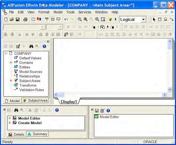
The ERWin Data Modeler workspace is shown in Figure 1.1.
Modeler Workspace
The top part of the workspace consists of Menu and Toolbars. The middle part of the workspace consists of two panes: the model explorer panel on the left providing a text based view of the data model and the diagram window panel on the right providing a graphical view of the data model. The lower part of the workspace consists of two panes: the action log panel on the left that displays a log of all changes made to the data model under design and the advisories panel that displays messages associated with the actions performed on the data model under design.
ERWin supports three model types for use by the database designer:
1. Logical: A conceptual model that includes entities, relationships, and attributes. This model type is essentially at the ER modeling level.
2. Physical: A database specific model that contains relational tables, columns and associated data types.
3. Logical/Physical: A single model that includes both the conceptual level objects as well as physical level tables. In this chapter we will use this model type.
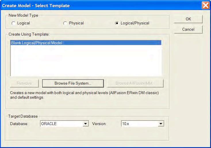
To create a model in ERWin, one should launch the program and then choose the “New” option from the File menu. The Create Model dialog appears as shown in Figure 1.2.
1.2: Create Model dialog window
In this dialog window, the user should choose the type of model. Typically the Logical/Physical model type should be chosen if the final goal is to produce a relational design for the database. The target database may also be chosen. In this case, Oracle 10.x version is chosen as the target database. In a future step, we will illustrate how ERWin can be used to generate SQL code to create the database objects in Oracle 10.x database.
The workspace for the new model will be populated by the system with a default name of Model_n. This name may be changed in the model explorer pane by right clicking the model name and choosing the Properties option. This brings up a new window in which the name and other properties of the model may be changed. Besides changing the model name, the “Transform” options should be checked. This would allow for many-to-many relationships to be transformed correctly into separate relational tables in the physical model. In addition any sub-type/super-type relationships will also be transformed correctly in the physical model.
1.2 Adding Entity Types
To add an entity type to the database design, the user may either right click the “Entities” entry in the model explorer pane and choose “New” or choose the “Entity” icon in the Menus and Toolbars section of the workspace and click in the diagram window panel. An entity box shows up in the diagram window panel with a default entity name (E/n) that can be changed either in the diagram window panel or in the model explorer pane. Figure 1.3 shows the addition of the EMPLOYEE entity type in the COMPANY database.
1.3: Add EMPLOYEE entity to the COMPANY database

To add attributes to the EMPLOYEE entity type, the user may right click within the EMPLOYEE entity box in the diagram window panel and choose “Attributes”. This brings up a separate window using which new attributes may be added. The attribute window is shown in Figure 1.4.
The user may now add attributes one at a time by clicking the “New” button. A separate window pops up as shown in Figure 1.5.
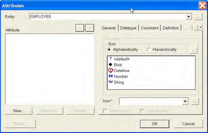
The user may choose an appropriate Domain (data type) and enter the Attribute Name and click OK. The data type may be further refined in the Attribute Window by choosing the Datatype tab and entering a precise data type. The user may also choose to designate this attribute as a primary key by selecting this option in the Attribute window.


After adding a few attributes to the EMPLOYEE entity type the Attributes window is shown in Figure 1.6.
In this way, we can create each of entity types: EMPLOYEE, DEPARTMENT, PROJECT, and DEPENDENT for the COMPANY database.
Weak Entity Sets
By default any entity type created as discussed so far is classified as an independent entity type. ERWin will classify an entity type as “weak” as soon as it participates in an identifying relationship. For example, the entity type DEPENDENT will be classified as “weak” in a subsequent step when we add the identifying relationship from EMPLOYEE to DEPENDENT in the next section. Weak entity types are denoted by rounded rectangles in the diagram window panel.

Multi-Valued Attributes
Multi-valued attributes such as the locations attribute for the DEPARTMENT entity type cannot be modeled easily with ERWin. To handle such attributes, a separate entity type LOCATIONS is created and a many-to-many relationship between DEPARTMENT and LOCATIONS will be established in the next section.
1.3 Adding Relationships
Three types of relationships are supported in ERWin: identifying, non-identifying, and many-tomany. ERWin classifies the child entity type in an identifying relationship as “weak”. To add a relationship, the user may simply right click the Relationships entry in the model explorer pane and choose “New”. This pops up a new relationship window as shown in Figure 1.7.
1.7: New Relationship Window
After choosing the parent and child entity types and the type of relationship and clicking OK, the new relationship is added and is reflected by a line connecting the two entity types in the diagram window panel. The many-to-many relationships are denoted by solid connecting lines, with two black dots at the two ends. Non-identifying relationships are denoted by a dashed connecting line with a black dot at many-end and a square-shaped symbol at the one-end. Identifying relationships are denoted by a solid connecting line with a black dot at the many-end and nothing special at the one-end.
After creating a new relationship, the user may add verb phrases and other properties of the relationship by right clicking the connecting line in the diagram and choosing properties.
In the case of the COMPANY database, we create the following relationships:
• One identifying relationship from EMPLOYEE to DEPENDENT.
• Two many-to-many relationships, one from EMPLOYEE to PROJECT and the other from DEPARTMENTS to LOCATIONS, and
• Four non-identifying relationships: from EMPLOYEE to DEPARTMENT (one-to-one for manages), from DEPARTMENT to EMPLOYEE (one-to-many for works for relationship), from EMPLOYEE to EMPLOYEE (one-to-many for supervisor/supervisee relationship), and from DEPARTMENT to PROJECT (one-to-many for the controls relationship).
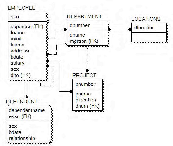
The final logical ER diagram from the diagram window panel is shown in Figure 1.8.
Notice that the two many-to-many relationships do not have the transforms applied yet. The transforms are shown in the physical ER diagram (obtained by switching from Logical to Physical in the Menu and Toolbar section) in Figure 1.9. Notice the introduction of the two new “entity types” for the two many-to-many relationships. These entity types are introduced because the transforms are defined at the model level.
1.4 Forward Engineering
ERWin provides a powerful feature called forward engineering that allows the database designer to convert the ER design into a schema generation SQL script for one or more target relational databases. The following SQL script is obtained for the COMPANY database by choosing ToolsForward EngineeringSchema-Generation option in the Menus and Toolbars section and clicking the “Preview” button.
CREATE TABLE DEPARTMENT ( dname VARCHAR2(20) NOT NULL , dnumber INTEGER NOT NULL , mgrssn NUMBER(9) NULL );
ALTER TABLE DEPARTMENT
ADD PRIMARY KEY (dnumber);
CREATE TABLE DEPARTMENT_LOCATIONS ( dnumber INTEGER NOT NULL , dlocation VARCHAR2(20) NOT NULL );

ALTER TABLE DEPARTMENT_LOCATIONS
ADD PRIMARY KEY (dnumber,dlocation);
CREATE TABLE DEPENDENT ( dependentname VARCHAR2(20) NOT NULL , sex CHAR NULL , bdate DATE NULL , relationship VARCHAR2(20) NULL , essn NUMBER(9) NOT NULL );
ALTER TABLE DEPENDENT
ADD PRIMARY KEY (dependentname,essn);
CREATE TABLE EMPLOYEE ( ssn NUMBER(9) NOT NULL , superssn NUMBER(9) NULL , fname VARCHAR2(20) NULL , minit CHAR NULL , lname VARCHAR2(20) NOT NULL , address VARCHAR2(50) NULL , bdate DATE NULL , salary NUMBER(8) NULL , sex CHAR NULL , dno INTEGER NULL );
ALTER TABLE EMPLOYEE
ADD PRIMARY KEY (ssn);
CREATE TABLE EMPLOYEE_PROJECT ( ssn NUMBER(9) NOT NULL , pnumber INTEGER NOT NULL , hours NUMBER(3) NULL );
ALTER TABLE EMPLOYEE_PROJECT
ADD PRIMARY KEY (ssn,pnumber);
CREATE TABLE LOCATIONS ( dlocation VARCHAR2(20) NOT NULL );
ALTER TABLE LOCATIONS
ADD PRIMARY KEY (dlocation);
CREATE TABLE PROJECT ( pnumber INTEGER NOT NULL , pname VARCHAR2(20) NULL , plocation VARCHAR2(20) NULL , dnum INTEGER NULL );
ALTER TABLE PROJECT ADD PRIMARY KEY (pnumber);
ALTER TABLE DEPARTMENT ADD ( FOREIGN KEY (mgrssn) REFERENCES EMPLOYEE(ssn) ON DELETE SET NULL);
ALTER TABLE DEPARTMENT_LOCATIONS ADD ( FOREIGN KEY (dnumber) REFERENCES DEPARTMENT(dnumber));
ALTER TABLE DEPARTMENT_LOCATIONS ADD ( FOREIGN KEY (dlocation) REFERENCES LOCATIONS(dlocation));
ALTER TABLE DEPENDENT ADD ( FOREIGN KEY (essn) REFERENCES EMPLOYEE(ssn));
ALTER TABLE EMPLOYEE ADD ( FOREIGN KEY (superssn) REFERENCES EMPLOYEE(ssn) ON DELETE SET NULL);
ALTER TABLE EMPLOYEE ADD ( FOREIGN KEY (dno) REFERENCES DEPARTMENT(dnumber) ON DELETE SET NULL);
ALTER TABLE EMPLOYEE_PROJECT ADD ( FOREIGN KEY (ssn) REFERENCES EMPLOYEE(ssn));
ALTER TABLE EMPLOYEE_PROJECT
ADD ( FOREIGN KEY (pnumber) REFERENCES PROJECT(pnumber));
ALTER TABLE PROJECT
ADD ( FOREIGN KEY (dnum) REFERENCES DEPARTMENT(dnumber) ON DELETE SET NULL);
The above SQL script contains table definitions and basic primary and foreign key constraints definitions. ERWin does provide a number of options to generate views, triggers, indices etc. and these can be set in the forward engineering schema generation window.
1.5 Supertype/Subtype Example
ERWin supports the creation of sub-type/super-type relationships between entity types. Consider the example in Figure 8.3 of the Elmasri/Navathe text in which a super-type entity VEHICLE consists of two sub-types CAR and TRUCK. To create this design in ERWin, the three entity types are created first. Then, the user may click the sub-type button (a circle with two parallel lines below the circle) in the Menus and Toolbars section, followed by clicking the super-type entity (VEHICLES) in the diagram window pane, followed by clicking the sub-type entity (CAR) in the diagram window pane. This process may be repeated for adding other sub-types (TRUCK in this example). The logical model for this example is shown in Figure 1.10.

Figure 1.10: Sub-type/Super-type Logical ER Diagram
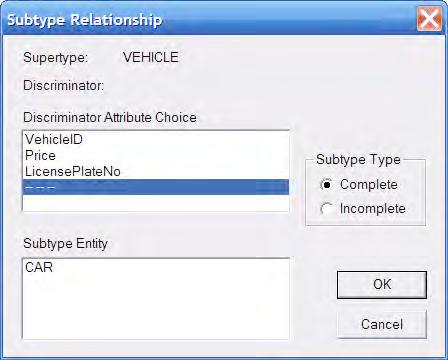
To customize the properties of the sub-type/super-type relationship, the user may right click the relationship symbol (circle with two parallel lines) and choose Subtype Relationship. This brings up a window shown in Figure 1.11. The user may choose “Complete” subtype (when all categories are known) or “Incomplete” subtype (when all categories may not be known). The user may also add verb phrases etc by right-clicking the relationship line and choosing properties as was done for ordinary relationships. ERWin also allows the user to choose a “discriminator” attribute for the sub-types (an attribute in the super-type whose values determine the sub-type object). If no discriminator attribute is defined, the user may choose “ ”.
The following SQL script is produced using the forward engineering feature of ERWin for the Vehicles example:
CREATE TABLE CAR (
MaxSpeed INTEGER NULL , NumOfPassengers INTEGER NULL , VehicleID INTEGER NOT NULL );
ALTER TABLE CAR ADD PRIMARY KEY (VehicleID);
CREATE TABLE TRUCK (
NumOfAxles INTEGER NULL , Tonnage INTEGER NULL , VehicleID INTEGER NOT NULL );
ALTER TABLE TRUCK ADD PRIMARY KEY (VehicleID);
CREATE TABLE VEHICLE (
VehicleID INTEGER NOT NULL , Price NUMBER(8,2) NULL , LicensePlateNo VARCHAR2(20) NULL );
ALTER TABLE VEHICLE ADD PRIMARY KEY (VehicleID);
ALTER TABLE CAR
ADD ( FOREIGN KEY (VehicleID) REFERENCES VEHICLE(VehicleID));
ALTER TABLE TRUCK
ADD ( FOREIGN KEY (VehicleID) REFERENCES VEHICLE(VehicleID));
Exercises
ER Modeling Problems
1. Consider the university database described in Exercise 7.16 of the Elmasri/Navathe text. Enter the ER schema for this database using a data-modeling tool such as ERWin.
2. Consider a mail order database in which employees take orders for parts from customers. The data requirements are summarized as follows:
• The mail order company has employees identified by a unique employee number, their first and last names, and a zip code where they are located.
• Customers of the company are uniquely identified by a customer number. In addition, their first and last names and a zip code where they are located are recorded.
• The parts being sold by the company are identified by a unique part number. In addirion, a part name, their price, and quantity in stock are recorded.
• Orders placed by customers are taken by employees and are given a unique order number. Each order may contain certain quantities of one or more parts and their received date as well as a shipped date is recorded.
Design an Entity-Relationship diagram for the mail order database and enter the design using a data-modeling tool such as ERWin.
3. Consider a movie database in which data is recorded about the movie industry. The data requirements are summarized as follows:
• Movies are identified by their title and year of release. They have a length in minutes. They also have a studio that produces the movie and are classified under one or more genres (such as horror, action, drama etc). Movies are directed by one or more directors and have one or more actors acting in them. The movie also has a plot outline. Each movie also has zero or more quotable quotes that are spoken by a particular actor acting in the movie.
• Actors are identified by their names and date of birth and act in one or more movies. Each actor has a role in the movie.
• Directors are also identified by their names and date of birth and direct one or more movies. It is possible for a director to act in a movie (not necessarily in a movie they direct).
